boc - swegon · boc 6 swego eserve h igh lte peci˜cations 20150805 dimensioning graphs boc- supply...
TRANSCRIPT

BOCLow velocity air diffuser with heating and cooling function
QUICK FACTS ○ For facilities with both heating and cooling needs
○ Switching of heating / cooling with manual control or motor control
○ For big facilities, such as factories, big shops, sport arenas
○ More free floor area
A I R F L O W - S O U N D L E V E L
EAGLE Ceiling
Size
30 dB(A) 35 dB(A) 340dB(A)
l/s m3/h l/s m3/h l/s m3/h
200 180 648 215 774 250 900
250 260 936 300 1080 350 1260
315 375 1350 440 1584 510 1836
400 590 2124 690 2484 790 2844
500 910 3276 1015 3654 1300 4680
630 1400 5040 1600 5760 1800 6480
Data gäller för öppet spjäll och vid 16 dB rumsdämpning. (150 m2 ekvivalent absorp-tionsarea. Alla värden gäller vid raksträcka utan störning på anslutande kanal).

BOC
2Swegon reserves the right to alter specifications. 20150805
ContentsTechnical description .......................................... 3
Design ...................................................................... 3
Materials and surface treatment ................................ 3
Adaptation ............................................................... 3
Accessories ............................................................... 3
Installation ................................................................ 3
Planning ................................................................... 3
Maintenance ............................................................. 4
Environment ............................................................. 4
Sizing ................................................................... 5BOC- Supply air ......................................................... 6
BOC - Supply air - Free suspension ............................ 8
Dimensioning graphs - BOC ...................................... 9
Dimensions and weights .................................. 10
Order key ........................................................... 10
Specification example ...................................... 10

320150805 Swegon reserves the right to alter specifications.
BOC
Technical descriptionDesignBOC is designed for rooms with high ceilings such as industrial premises, large shops, sports halls etc. It has an octagonal shape and the upper section of the terminal next to the connection spigot is equipped with the aero-dynamic discs which are unique to our products.
The lower section has a perforated, removable front cover. Inside this there is a distribution plate which is equipped with flexible distribution system, Varizon®. The disc section and the perforated section are separated by a damper function. This is controlled by means of an electric motor (1) or manual control (2), see figure 1. BOC is mounted to a wall or pillar using the brackets supplied with the terminal.
Materials and surface treatmentBOC is manufactured in galvanized sheet steel. The discs and the Varizon® system are manufactured in PP (poly-propylene). The whole terminal unit is powder painted in a dusty grey shade, RAL 7037. The unit is also available in other standard colours: White aluminium RAL 9006, jet black RAL 9005, grey aluminium RAL 9007 and signal white RAL 9003 (NCS 0500).
AdaptationBesides the standard range, it is possible to adapt the product to customer specifications. Please contact your nearest sales office for more information.
Accessories
Commissioning damperCRM1. Commissioning damper (4) with measuring unit for commissioning the air volume. See figure 1.
ClampFSR. Clamp (5) made of galvanised sheet steel, used for facilitating installation and removal of units. See figure 1.
Heating principles. Cooling principle.
Controller:VHC controller (1) resets motor controlled diffusers intended both for cooling and heating with supply air. The controlling parameter is the temperature difference between supply air and room air. See separate product sheet for VHC. See figure 2.
InstallationMounting brackets (3) are supplied. These are fastened to the wall and then to BOC. See figure 1.
PlanningBOC is designed to be mounted at a height of 2.5 – 5 m, measured from floor level to the lower edge of the termi-nal. The height is related to the size of the terminal, the volume of air and temperature drop (see technical data). The changeover damper is most simply controlled from the air handling unit (accessory) which gives the current supply air temperature. A control signal may also be taken from a duct sensor.
N.B. The sound level in he engineering diagram's is valid at 150 m2 equivalent sound absorption area. This fact makes it important to check the air velocities in the connecting ducts to the terminals. Extra consideration has to be taken on how the ducts can be connected to the terminals. See figure 4.

BOC
4Swegon reserves the right to alter specifications. 20150805
CommissioningThe airflow is commissioned using the adjustable mea-suring unit (4) which is placed in the duct before the BOC unit. See figure 1.
MaintenanceBOC is cleaned when necessary using lukewarm water with detergent added. Access to the inner parts is pos-sible via the removable perforated front plates.
EnvironmentThe Declaration of construction materials is available at www.swegon.com.
5
Figure 1. Installation.
ConnectionVHC is connected to a 24 AC power supply according to wiring diagrams, Figure 2 and figure 3.
Figure 3b. The wiring diagram shows the supply terminal con-nections for a Sauter damper actuator fitted to the BOC.Key to Figure 3b:1 = VHC control unit. 2 = Duct temperature sensor, included (DT). 3 = Room temperature sensor, included (RT). 4 = Setting the switch over temperature.
Figure 2. BOC with VHC.
Key to Figure 2: 1 = VHC control unit with duct temperature sensor. 2 = Room temperature sensor. 3 = Connection box. 4 = Fixed actuator cable 0,4 m.
Sauter:ASM115SF901 (24 V AC/DC)ASM115F901 (230 V AC)
Figure 3a. Wiring diagram for Sauter, 2 point regulation.
BU = blueBN = brownBK = blackRD = redGY = grey

520150805 Swegon reserves the right to alter specifications.
BOC
Figure 4. E.g. of how different duct connections affect the sound level of the terminal. See also the Technical chapter under Acous-tics - Planning Tips.
Sizing• Sound level dB(A) applies to rooms with 150 m²
absorption area and measured 2 m from the dis-placement unit and with at a straight section without disturbance on straight duct section.
• Data for electric actuator Sauter ASM 115 SF901 Supply voltage AC 24 V ±20%, 50...60 Hz DC 24 V ±20% Power consumption 4,8 W 8,7 VA Operating time 60/120 sek (50 Hz)
Sound data - BOCSound power level Lw(dB) Table KOK
Size Mid-frequency (octave band) Hz
BOC 63 125 250 500 1000 2000 4000 8000
200 17 15 16 15 12 2 -12 -14
250 15 17 16 18 11 0 -13 -15
315 15 17 16 18 10 -2 -13 -10
400 18 18 19 16 9 -3 -14 -12
500 18 17 18 16 10 -2 -13 -11
630 19 20 19 16 8 -3 -11 -7
Tol. ± 2 2 2 2 2 2 2 2
Sound attenuation DL (dB) Table DL
Size Mid-frequency (octave band) Hz
BOC 63 125 250 500 1000 2000 4000 8000
200 16 12 6 2 2 3 5 4
250 15 10 5 2 2 3 4 5
315 14 9 4 1 0 1 2 2
400 10 6 4 1 1 1 1 1
500 8 4 3 1 1 1 1 1
630 6 3 2 1 1 1 0 0
Tol. ± 2 2 2 2 2 2 2 2
Table duct connections.
Duct connections
m/s A B C D
4-5 m/s + 2 + 6 + 3 + 3
6-8 m/s + 4 + 10 + 6 + 6
Effects on sound levels (dB) for different duct connections and different equivalent sound absorption areas, 150 and 10m.

BOC
6Swegon reserves the right to alter specifications. 20150805
Dimensioning graphsBOC- Supply air
Airflow - Throw - Over temperatures• The graphs must not be used for commissioning.
• The graphs show the airstream penetration depth in the room measured from the lower edge of the termi-nal.
Example: At an airflow of 660 l/s from a BOC 400, a downward penetration depth of 3.0 m is obtained at +5 K over-temperature. If +10 K over-temperature is desired, the penetration depth decreases by a factor of 0.66, i.e. 3.0 m x 0.66 = 1.98 m.
Diagram 2. Correction factor for other over temperatures (kf)
Diagram 1. Penetration depth (m) at +5 K over temperature.

720150805 Swegon reserves the right to alter specifications.
BOC
BOC - Supply air - Wall mounted
Airflow - Affected zone - Under temperature• The graphs must not be used for commissioning.
• The graphs illustrate the affected zone a0,20 and b0,20 for the selected size, airflow and mounting height. The affected zone refers to the distance to the isovel limit 0.2 m/s at a given Dt. In this case Dt designates the difference between the room air temperature measured 1.2 m above the floor and the supply air temperature. N.B. not the difference between supply and exhaust air temperature.
• Example: Decide mounting height and terminal size. BOC 315 with a mounting height of 3.2 m has a a0,2 & b0,2 gives a 4 m affected zone at an airflow of l/s 240 a0,2 & b0,2 gives a 6 m affected zone at an airflow of l/s 360
• If other affected zones are required, the following formula may be used:
alt.*)
qx
= required air flow
a0,2x*) = required affected zone
qa
= air flow at known affected zone
a0,2x*) = known affected zone
Example:
Data at Dt -6K are calculated in accordance with: a
0,2x*) Dt 3 K · 1,25*) a
0,2x = b
0,2x
Diagram 3. Affected zone - wall mounting at Dt = 3K
450=
360= a
0,2x*)
= 7,5 ma
0,2x*) 6
qx =
qa0,2x
a0,2x
a0,2x
qx =
qb0,2x
b0,2x
b0,2x

BOC
8Swegon reserves the right to alter specifications. 20150805
BOC - Supply air - Free suspension
Airflow - Affected zone - Under temperature
• The graphs must not be used for commissioning.
• The graphs illustrate the affected zone a0,20 for the selected size, airflow and mounting height. The affected zone refers to the distance to the isovel limit 0.2 m/s at a given Dt. In this case Dt designates the dif-ference between the room air temperature measured 1.2 m above the floor and the supply air temperature. N.B. not the difference between supply and exhaust air temperatures.
• Example: Decide mounting height and terminal size. BOC 315 with a mounting height of 3.4 m has a 4 m affected zone a0,2 at an airflow of l/s 500 6 m affected zone a0,2 at an airflow of l/s 750
• If other affected zones are required, the following formula may be used:
qx
= required air flow
a0,2x
= required affected zone
qa
= air flow at known affected zone
a0,2
= known affected zone
Example:
Data at Dt -6 K are calculated in accordance with: a0,20Dt 3° · 1,25
Diagram 4. Affected zone - free suspension at Dt = 3K
950=
750= a
0,2x= 7,6 m
a0,2x 6
qx =
qa0,2
a0,2x
a0,2

920150805 Swegon reserves the right to alter specifications.
BOC
Dimensioning graphs - BOC
Airflow - Pressure drop - Sound levels• The graphs must not be used for commissioning.
• The graph shows data for sound levels in a room with an equivalent absorption area of 150 m2 and measured 2 m from the displacement unit and with at a straight section without disturbance on straight duct section. See figure 4 how different duct connetions will affect the sound level.
• The dB(C) value is normally 6-9 dB higher than the dB(A) value.
• The graph shows the pressure line for open booster damper (cooling). When the damper is closed, the sound level increases by approx. 5 dB and the total pressure by approx. 8 Pa (heating).
BOC 200pt Papt Pa
200 300 400 500 1000 m3/h
pt Papt Pa
40 50 100 200 300 l/s 400345
10
20
304050
100
2025
3035
40 dB(A)
BOC 250pt Papt Pa
400 500 1000 2000 m3/h
pt Papt Pa
100 200 300 400 500 l/s 10002
345
10
20
304050
100
2025
3035
40 dB(A)
BOC 315pt Papt Pa
400 500 1000 2000 m3/h
pt Papt Pa
100 200 300 400 500 l/s 10002
345
10
20
304050
100
2025
3035
40 dB(A)
BOC 400pt Papt Pa
1000 2000 3000 4000 m3/h
pt Papt Pa
200 300 400 500 1000 l/s2
345
10
20
304050
100
2025
3035
40 dB(A)
BOC 500pt Papt Pa
1000 2000 3000 4000 5000 m3/h
pt Papt Pa
200 300 400 500 1000 l/s 20002
345
10
20
304050
100
2025
3035
40 dB(A)
BOC 630pt Papt Pa
2000 3000 4000 5000 10000 m3/h
pt Papt Pa
400 500 1000 2000 3000 l/s 40002
345
10
20
304050
100
2025
3035
40 dB(A)
BOC
10Swegon reserves the right to alter specifications. 20150805
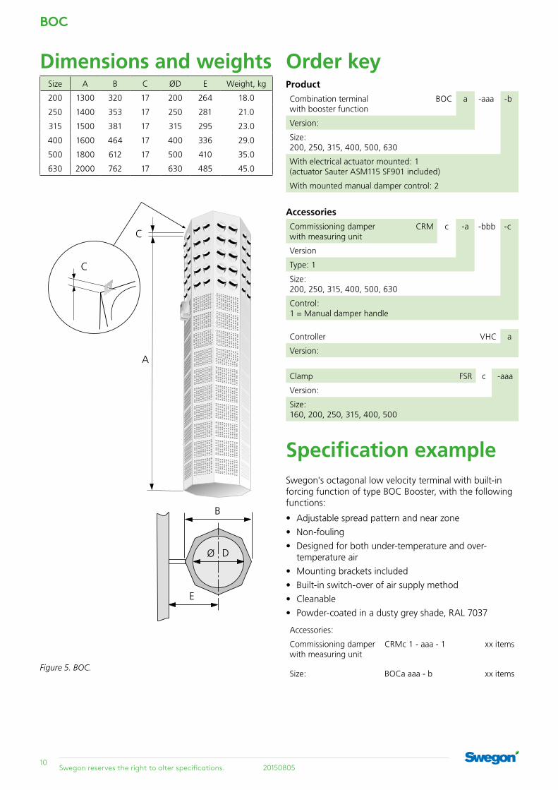
Dimensions and weightsSize A B C ØD E Weight, kg
200 1300 320 17 200 264 18.0
250 1400 353 17 250 281 21.0
315 1500 381 17 315 295 23.0
400 1600 464 17 400 336 29.0
500 1800 612 17 500 410 35.0
630 2000 762 17 630 485 45.0
Figure 5. BOC.
Specification example Swegon's octagonal low velocity terminal with built-in forcing function of type BOC Booster, with the following functions:
• Adjustable spread pattern and near zone
• Non-fouling
• Designed for both under-temperature and over- temperature air
• Mounting brackets included
• Built-in switch-over of air supply method
• Cleanable
• Powder-coated in a dusty grey shade, RAL 7037
Accessories:
Commissioning damper with measuring unit
CRMc 1 - aaa - 1 xx items
Size: BOCa aaa - b xx items
Order keyProduct
Combination terminal with booster function
BOC a -aaa -b
Version:
Size: 200, 250, 315, 400, 500, 630
With electrical actuator mounted: 1 (actuator Sauter ASM115 SF901 included)
With mounted manual damper control: 2
Accessories
Commissioning damper with measuring unit
CRM c -a -bbb -c
Version
Type: 1
Size: 200, 250, 315, 400, 500, 630
Control: 1 = Manual damper handle
Controller VHC a
Version:
Clamp FSR c -aaa
Version:
Size: 160, 200, 250, 315, 400, 500