boca: mechanical code - · pdf fileboca: mechanical code. the ... the development of...
TRANSCRIPT

By Authority OfTHE UNITED STATES OF AMERICA
Legally Binding Document
By the Authority Vested By Part 5 of the United States Code § 552(a) and Part 1 of the Code of Regulations § 51 the attached document has been duly INCORPORATED BY REFERENCE and shall be considered legally binding upon all citizens and residents of the United States of America. HEED THIS NOTICE: Criminal penalties may apply for noncompliance.
Official Incorporator:THE EXECUTIVE DIRECTOROFFICE OF THE FEDERAL REGISTERWASHINGTON, D.C.
Document Name:
CFR Section(s):
Standards Body:
e


The BOCA ® National Mechanical Code/1993
Model building regulations for the protection of public health, safety and welfare.
EIGHTH EDITION
As recommended and maintained by the voting membership of
BUILDING OFFICIALS & CODE ADMINISTRATORS INTERNATIONAL, INC. 4051 W. Flossmoor Rd.
Founded in 1915
3592 Corporate Dr., Ste. 107 Columbus, OH 43231-4987 Telephone 614/890-1064 FAX 614/890-9712
Country Club Hills, IL 60478-5795
REGIONAL OFFICES
Towne Centre Complex 10830 E. 45th Street, Ste. 200
Tulsa, OK 74146-3809 Telephone 918/664-4434
FAX 918/664-4435
708/799-2300 FAX 708/799-4981
3 Neshaminy Interplex, Ste. 301 Trevose, PA 19053-6939 Telephone 215/638-0554
FAX 215/245-4705

NOTE: The BOCA National Codes are designed for adoption by state or local governments by reference only. Jurisdictions adopting them may make necessary additions, deletions and amendments in their adopting document. Incorporation of any part of the BOCA National Codes in codes published by states, local governments, regulatory agencies, individuals or organizations is expressly prohibited. When your jurisdiction has adopted one or more of the BOCA National Codes, please send a copy of the adopting document to the BOCA Executive offices.
Once this material has been adopted by a rule-making jurisdiction, other than by reference, all parties, including the rule-making jurisdiction, may reproduce the material in whole or in part subject only to a nonexclusive, royalty-bearing license with Building Officials & Code Administrators International, Inc. Any party desiring such a license should contact: Executive Director, BOCA International, 4051 West Flossmoor Road, Country Club Hills, Illinois 60478-5795.
Copyright, 1993, Building Officials and Code Administrators, International, Inc.
All rights reserved. No part of this book may be reproduced or transmitted in any form or by any means, electronic or mechanical, including photocopy, recording or by an information storage and retrieval system without advance permission in writing from the publisher. For information, address: Building Officials and Code Administrators International, 4051 West Flossmoor Road, Country Club Hills, Illinois 60478-5795.
BOCA ® is the trademark qlBuilding Officials and Code Administrators International, Inc., and is registered in the U.S. Patent and Trademark Office.
Printed in the United States of America First printing: March, 1993

PREFACE
The BOCA National Mechanical Code was initially prepared and updated on the premise that adequate code requirements are essential to the safe installation and maintenance of all mechanical equipment and systems in order to protect the public health, safety and welfare.
The BOCA National Mechanical C ode sets forth comprehensive regulations for the safe installation and maintenance of mechanical facilities where great reliance was previously placed on accepted practice and engineering standards. By establishing the end result to be accomplished rather than the method to be followed, the BOCA National Mechanical Code allows freedom and nexibility in the development of mechanical systems. The code adopts nationally recognized standards as the criteria for evaluation of minimum safe practice, or for determining the performance of materials or systems of construction. The application of these standards is stated in the text of the code requirements, and the standards are listed and identified in Chapter 21, making it practical and convenient to update any standard as it is revised or reissued by the sponsoring agency.
This eighth edition presents the BOCA National Mechanical Code as originally issued with changes through 1992 and with celtain editorial changes made to maintain the sequence of the code and to update the references to standards.
This code, as are the other codes published by Building Officials and Code Administrators International, is kept up to date through the review of changes proposed by code enforcement officials, industry and design professionals, and other interested persons and organizations. Proposed changes are discussed in a public hearing, carefully reviewed by committees, and acted upon by code enforcement officials in an open meeting of the organization. A new edition such as this is then prepared every three years, and contains all approved changes since the previous edition.
Changes as described above do not just happen. The BOCA National Mechanical Code is dedicated to the thousands of code enforcement officials from throughout the United States and Canada; to the engineers, architects, technicians, builders, contractors, material producers, trade associations and others who voluntarily collaborated in its preparation; and to the members of the code changes committees and their constituent committees, who participated in the important work of keeping the code abreast of new developments in construction technology. These individuals have given unstintingly of their time and their talents to produce and maintain this performance-type code, which has been widely recognized, highly respected, and adopted by countless communities.
Use of the BOCA National Mechanical Code or any of the other BOCA National Codes within a government jurisdiction is intended to be accomplished only through adoption by reference in a proceeding of the jurisdiction's board, council, or other authoritative governing body. At the time of adoption, jurisdictions should insert the appropriate information in those passages of a code requiring specific local information, such as the date of adoption, name of adopting jurisdiction, dollar amount of fines and permit costs, etc. These passages are shown in bracketed small capital letters in the codes, and are also listed in the sample adoption ordinance page of each code for which the local adoption information is required. Additionally, jurisdictions may amend or modify BOCA National Code provisions to accomplish desired local requirements, although use of the codes in substantially original and standardized form is encouraged by the BOCA organization. A sample draft of an adopting ordinance for the BOCA National Mechanical Code is provided on page vii.
This document has been developed under the published procedures of Building Officials and Code Administrators International, Inc. These procedures are designed to obtain the views and comments of those in the construction industry willing to participate. While these procedures assure the highest degree of care, neither BOCA, its members, nor those participating in its activities accepts any liability resulting from compliance or noncompliance with the provisions given herein, for any restrictions imposed on materials or processes, or for the completeness of the text.
BOCA has no power or authority to police or enforce compliance with the contents of this code. It is only the governmental body that enacts the code into law that does so.
iii

iv
NOTE TO BOCA@ NATIONAL CODE USERS
The 1993 editions of the BOCA National Codes contain, for the benefit and convenience of code users, vertical lines in the outside margins of some pages.
As in previous editions, vertical lines in the margin indicate approved changes to the text of code requirements. Editorial changes are not so marked. For example, lines shown in the margins of the 1993 BOCA National Codes indicate technical content changes since the 1990 editions. Asterisks in the margin indicate locations from which 1990 code text has been deleted. Unlike the 1990 editions, these asterisks are no longer used to indicate text that has moved to a different location in the code. These features are designed to streamline the review process for jurisdictions wishing to adopt current, up-to-date provisions.
Several additional features are reflected in the 1993 editions of the BOCA National Codes. Definitions of terms have been rearranged in order to locate them within the chapter or section
that represents the predominant subject matter associated with each term. Definitions related predominantly to Chapter 1 and those that have broad applicability throughout the code remain in full in Chapter 2. All defined terms are listed alphabetically in Chapter 2 followed by either the text of the definition or a reference to the section number that contains the text of the definition. Selected defined terms are italicized where they appear in the code in the same manner as in previous editions.
Additionally, an indenting feature is used in tandem with the codes' decimal-based section numbering system to indicate the hierarchy of each subsection.
The values stated in the U.S. customary units of measurement are to be regarded as code requirements. The metric equivalents of U.S. customary units may be approximate. Metric equivalents are not indicated for materials identified by nominal sizes. For actual dimensions refer to the appropriate material standard listed in Chapter 21. The nominal sizes included in the BOCA National Codes indicate the common designation of materials by that industry.

A GUIDE TO USE OF THE BOCA® NATIONAL MECHANICAL CODE
The format and provisions of the BOCA National Mechanical Code are designed to provide units of government with effective minimum requirements for safe mechanical systems.
The following step-by-step approach is recommended for use in determining the code's application to particular building mechanical systems within a governmental jurisdiction.
1. Mechanical equipment and appliances: Determine that mechanical equipment and appliances conform to and are installed in compliance with the requirements of Chapters 4, 6, 13, 14, 15 and 18.
2. Fuel supply: Determine compliance with gas piping requirements (Chapter 8). Determine compliance with fuel oil piping requirements (Chapter 9).
3. Combustion air: Determine that adequate combustion air is provided for all fuel-fired equipment (Chapter 10).
4. Chimneys and vents: Determine compliance with chimney and vent requirements (Chapter 12).
5. Duct and piping: Determine compliance with air distribution requirements (Chapter 3). Determine compliance with hydronic piping requirements (Chapter 7).
6. Kitchen exhaust: Determine compliance with kitchen exhaust requirements (Chapter 5).
7. Ventilation: Determine compliance with ventilation air requirements (Chapter 16).
8. Energy conservation: Determine compliance with energy conservation requirements (Chapter 19).
v


ADOPTION INFORMATION
The BOCA National Codes are designed and promulgated to be adopted by reference by ordinance. Jurisdictions wishing to adopt the BOCA National Mechanical C odell 993 as enforceable minimum mechanical safety requirements should insure that certain factual information is included in the adopting ordinance at the time adoption is being considered by the appropriate governmental body. The following sample adoption ordinance addresses several key elements of a code adoption ordinance, including the information required for insertion into the code text.
SAMPLE ORDINANCE FOR ADOPTION OF THE 1993 BOCA NATIONAL MECHANICAL CODE
AN ORDINANCE ESTABLISHING THE MINIMUM REGULATIONS GOVERNING THE DESIGN, INSTALLATION AND CONSTRUCTION OF MECHANICAL SYSTEMS, BY PROVIDING REASONABLE SAFEGUARDS TO PROTECT THE PUBLIC HEALTH AND SAFETY AGAINST THE HAZARDS OF INADEQUATE, DEFECTIVE OR UNSAFE MECHANICAL SYSTEMS AND INSTALLATIONS; KNOWN AS THE MECHANICAL CODE; AND REPEALING OF EXISTING ORDINANCE NUMBER (Present Ordinance, ifany) OF THE (Type of Jurisdiction) OF (Name of Jurisdiction), STATE OF (State Name).
Be it ordained by the (Governing Body) of the (Name of Jurisdiction) as follows:
SECTION 1. ADOPTION OF MECHANICAL CODE.
That a certain document, three (3) copies of which are on file in the office of the (Jurisdiction's Keeper o.lRecords) of the (Type of Jurisdiction) of (Name of Jurisdiction), being marked and designated as "The BOCA National Mechanical Code, Eighth Edition, 1993," as published by Building Officials and Code Administrators International, Inc., be and is hereby adopted as the Mechanical Code of the (Type of Jurisdiction) of (Name of Jurisdiction) in the State of (State Name); for the control of buildings and structures as herein provided; and each and all of the regulations, provisions, penalties, conditions and terms of the said BOCA National Mechanical Code are hereby referred to, adopted and made a part hereof, as if fully set out in this Ordinance, with the additions, insertions, deletions and changes, if any, prescribed in Section 3 of this Ordinance.
SECTION 2. INCONSISTENT ORDINANCES REPEALED.
That Ordinance Number (Present Ordinance Number) of the (Type of Jurisdiction) of (Name of Jurisdiction) entitled (Full Title of Present Ordinance) and all other ordinances or parts of ordinances in conflict herewith are hereby repealed.
SECTION 3. ADDITIONS, INSERTIONS AND CHANGES.
That the following sections are hereby revised as follows:
Section M-101.l (page I, second line). Insert: (Name of Jurisdiction).
Section M-113.2 (page 4, third line). Insert: (Fee Schedule).
Section M-113.3 (page 4, third line). Insert: (Fee Schedule).
Section M-116.4 (page 5, seventh, eighth and ninth lines). Insert: (Offense, Dollar Amount, Number of Days).
Section M-117.2 (page 5, fifth and sixth lines). Insert: (Dollar Amounts in Two Locations).
SECTION 4. SAVING CLAUSE
That nothing in this Ordinance or in the Mechanical Code hereby adopted shall be construed to affect any suit or proceeding impending in any court, or any rights acquired, or liability incurred, or any cause or causes of action acquired or existing, under any act or ordinance hereby repealed as cited in Section 2 of this Ordinance; nor shall any just or legal right or remedy of any character be lost, impaired or affected by this Ordinance.
SECTION S. DATE OF EFFECT.
That the (Jurisdiction's Keeper of Records) shall certify to the adoption of this Ordinance and cause the same to be published as required by law; and this Ordinance shall take full force and effect (Time Period) after this date of final passage and approval.
VII


TABLE OF CONTENTS
Chapter 1
Section
M-101.0 M-102.0 M-103.0 M-104.0 M-10S.0 M-106.0 M-107.0 M-108.0 M-109.0 M-110.0 M-111.0
ADMINISTRATION
Page
General ............................ 1 Applicability ........................ 1 Repairs and maintenance ............. 1 Validity ............................ 1 Department of mechanical inspection .... 1 Duties and powers of the code official .... 2 Approval ........................... 2 Application for permit ................. 3 Permits ............................ 3 Demolition of structures ............... 4 Moved structures .................... 4
Section
M-112.0 M-113.0 M-114.0 M-115.0 M-116.0 M-117.0 M-118.0 M-119.0 M-120.0 M-121.0
· . . . . . . . . . . . . . . . . . . . . .. 1
Page
Conditions of permit ................. 4 Fees ............................. 4 Inspections ........................ 4 Workmanship ...................... 5 Violations . . . . . . . . . . . . . . . . . . . . . . . . .. 5 Stop work order . . . . . . . . . . . . . . . . . . . .. 5 Notice of approval . . . . . . . . . . . . . . . . . .. 6 Unsafe conditions .................. , 6 Emergency measures . . . . . . . . . . . . . . .. 6 Means of appeal .................... 6
Chapter 2 DEFINITIONS.............................................. 9
M-201.0 General ............................ 9 M-202.0 General definitions ................... 9
Chapter 3
M-301.0 M-302.0 M-303.0 M-304.0 M-305.0 M-306.0
M-307.0 M-308.0
Chapter 4
M-401.0 M-402.0 M-403.0 M-404.0 M-405.0
Chapter 5
M-501.0 M-502.0 M-503.0
M-504.0
AIR DISTRIBUTION SYSTEMS ....
General ........................... 13 Definitions ........................ 13 Plenums .......................... 13 Duct construction ................... 14 Flexible ducts and connectors ......... 15 Duct coverings, linings, tape and
vibration isolation connectors ........ 15 Duct installation .................... 16 Outside air exhaust and intake
openings ........................ 16
MECHANICAL EQUIPMENT .....
General ........................... 21 Definitions ........................ 21 Equipment approval ................. 21 Labeling .......................... 21 Equipment installation ............... 22
KITCHEN EXHAUST EQUIPMENT . .
General ........................... 25 Where required .................... 25 Factory-built commercial hoods
and ducts ....................... 25 Commercial hood design ............. 25
M-309.0 M-310.0 M-311.0 M-312.0 M-313.0 M-314.0 M-315.0
M-406.0 M-407.0 M-408.0 M-409.0 M-410.0
M-505.0 M-506.0 M-507.0 M-508.0 M-509.0
· ...................... 13
Systems control . . . . . . . . . . . . . . . . . . .. 16 Filters ............................ 17 Hazardous exhaust systems . . . . . . . . .. 17 Clothes dryer exhaust . . . . . . . . . . . . . .. 18 Fire dampers . . . . . . . . . . . . . . . . . . . . .. 18 Smoke control systems . . . . . . . . . . . . .. 18 Dust, stock and refuse conveyor
systems ........................ 18
· ...................... 21
Hazardous location installation . . . . . . .. 22 Outdoor installation . . . . . . . . . . . . . . . . . 22 Boiler rooms and furnace rooms ....... 22 Electric installation ................. 22 Energy-saving devices .............. 23
· ...................... 25
Grease removal . . . . . . . . . . . . . . . . . . .. 26 Commercial duct systems . . . . . . . . . . .. 26 Clearance in commercial systems ..... 26 Suppression for commercial systems . . . 26 Test and cleaning schedule ........... 27
ix

THE BOCA NATIONAL MECHANICAL CODE/1993
Chapter 6
Section
M-601.0 M-602.0 M-603.0 M-604.0 M-605.0
Chapter 7
M-701.0 M-702.0 M-703.0 M-704.0 M-705.0 M-706.0
Chapter 8
M-801.0 M-802.0 M-803.0 M-804.0 M-805.0 M-806.0 M-807.0 M-808.0
BOILERS AND WATER HEATERS ..
Page
General ........................... 29 Definitions ........................ 29 Water heaters ...................... 29 Boiler connections .................. 29 Safety and pressure relief valves ....... 29
HYDRONIC PIPING . . . . . . . . . .
General ........................... 31 Definitions ........................ 31 Material ........................... 31 Joints and connections .............. 31 Expansion and contraction ............ 32 Pipe support ....................... 33
GAS PIPING SYSTEMS . . . .....
General ........................... 35 Definitions ........................ 35 Piping material ..................... 35 Joints and connections .............. 36 Sizing of gas piping systems .......... 37 Gas flow controls ................... 38 Underground gas piping .............. 43 Outside above-ground piping .......... 44
Section
M-606.0 M-607.0 M-608.0 M-609.0 M-610.0
M-707.0 M-708.0 M-709.0 M-710.0 M-711.0
M-809.0 M-810.0 M-811.0 M-812.0 M-813.0 M-814.0 M-815.0 M-816.0
· ...................... 29
Page
Steam boiler equalizing pipe .......... 29 Boiler low-water cutoff . . . . . . . . . . . . . . . 30 Steam blowoff valve ................ 30 Hot water boiler expansion tank . . . . . . . 30 Gauges .......................... 30
· ...................... 31
Piping installation .................. 33 Pipe insulation . . . . . . . . . . . . . . . . . . . . . 33 Valves ........................... 34 Transfer fluid ...................... 34 Tests ............................ 34
· ...................... 35
Inside building gas piping ............ 44 Hangers and supports . . . . . . . . . . . . . . . 44 Shutoff valves ..................... 44 Outlets and connections .... . . . . . . . . . 44 Gas-dispensing systems ............. 44 Supplemental and standby gas supply . . 44 Testing ........................... 45 Purging gas piping ................. 45
Chapter 9 FLAMMABLE AND COMBUSTIBLE LIQUID STORAGE AND PIPING SYSTEMS .......... 47
M-901.0 M-902.0 M-903.0 M-904.0 M-905.0
M-906.0
General ........................... 47 Definitions ........................ 47 Material ........................... 47 Joints and connections .............. 48 Corrosion protection and leak
detection ........................ 48 Hangers and supports ............... 49
Chapter 10 COMBUSTION AIR ......... .
M-1001.0 General ........................... 53 M-1002.0 Definitions ........................ 53 M-1003.0 Inside air .......................... 53 M-1004.0 Outdoor air ........................ 53
M-907.0 M-908.0 M-909.0 M-910.0 M-911.0 M-912.0
Underground piping ................. 49 Underground storage tank installation .. 49 Fuel oil system installation ........... 50 Fuel-dispensing systems ............ 50 Fuel oil valves ..................... 50 Tests ............................ 50
· ...................... 53
M-1005.0 Direct connection .................. 53 M-1006.0 Mechanical ventilation ............... 53 M-1007.0 Opening obstructions ............... 53
Chapter 11 CLEARANCE REDUCTION ....................................... 55
M-1101.0 General ........................... 55 M-1102.0 Reduced clearances ................ 55
x

Chapter 12 CHIMNEYS AND VENTS ...... .
Section Page
M-1201.0 General ........................... 57 M-1202.0 Definitions ........................ 57 M-1203.0 Where required .................... 57 M-1204.0 Vent system ....................... 58 M-1205.0 Factory-built chimneys ............... 58 M-1206.0 Masonry chimneys, general
requirements ..................... 58 M-1207.0 Masonry chimneys for low-heat
appliances ...................... 58 M-1208.0 Masonry chimneys for medium-heat
appliances ...................... 59 M-1209.0 Masonry chimneys for high-heat
appliances ...................... 59
Chapter 13 MECHANICAL REFRIGERATION . . .
M-130 1.0 General ........................... 67 M-1302.0 Definitions ........................ 67 M-1303.0 Maximum quantities of refrigerant ...... 67 M-1304.0 Refrigeration piping and equipment ..... 68 M-1305.0 Pressure-limiting devices ............. 69
TABLE OF CONTENTS
Section Page
M-121 0.0 Metal chimneys, general requirements ...... . . . . . . . . . . . . .. 60
M-1211.0 Metal chimneys for low-heat appliances . . . . . . . . . . . . . . . . . . . . .. 60
M-1212.0 Metal chimneys for medium-heat appliances . . . . . . . . . . . . . . . . . . . . .. 60
M-1213.0 Metal chimneys for high-heat appliances ...................... 61
M-1214.0 Multiple connections ................ 61 M-1215.0 Exhausters ....................... 61 M-1216.0 Connectors ....................... 62 M-1217.0 Dampers ......................... 65 M-1218.0 Tests ............................ 65
51
· ...................... 61
M-1306.0 Pressure relief protection ............ 69 M-1307.0 Class T machinery rooms . . . . . . . . . . .. 70 M-1308.0 General machinery rooms. . . . . . . . . . .. 70 M-1309.0 Tests ............................ 70
Chapter 14 FIREPLACES, SOLID FUEL-BURNING AND GAS ACCESSORY APPLIANCES ........... 11
M-1401.0 General ........................... 71 M-1402.0 Room heaters ...................... 71 M-1403.0 Factory-built fireplaces ............... 71
Chapter 15 INCINERATORS AND CREMATORIES.
M-1501.0 General ........................... 73 M-1502.0 Definitions ........................ 73 M-1503.0 Waste classification ................. 73 M-1504.0 Incinerator classification .............. 75 M-1505.0 Design ........................... 75
Chapter 16 VENTILATION AIR .......... .
M-1601.0 General ........................... 83 M-1602.0 Definitions ........................ 83 M-1603.0 Natural ventilation .................. 83
Chapter 17 AIR QUALITY . . . . . . . . . . . . .
M-1701.0 General ........................... 87 M-1702.0 Definitions ........................ 87 M-1703.0 Particulate matter in gases ........... 87
Chapter 18 SOLAR HEATING AND COOLING SYSTEMS
M-1801.0 General ........................... 89 M-1802.0 Installation ........................ 89
M-1404.0 Masonry fireplaces ................. 71 M-1405.0 Barbecue pits ..................... 72 M-1406.0 Gas accessories .. . . . . . . . . . . . . . . . .. 72
· ...................... 13
M-1506.0 Construction ...................... 77 M-1507.0 Commercial and industrial incinerators.. 77 M-1508.0 Requirements by class of incinerator .. , 77 M-1509.0 Chimneys ........................ 79 M-1510.0 Crematories ....................... 81
· ...................... 83
M-1604.0 Mechanical ventilation ............... 83 M-1605.0 Mechanical exhaust ................ 85 M-1606.0 Ventilation of uninhabited spaces ...... 86
· ...................... 81
M-1704.0 Ringelmann standards .............. 87 M-1705.0 Sulfur dioxide ..................... 87 M-1706.0 Nuisance ......................... 87
· ...................... 89
M-1803.0 Heat transfer fluids ................. 89 M-1804.0 Materials ......................... 90
xi

THE BOCA NATIONAL MECHANICAL CODE/1993
Chapter 19 ENERGY CONSERVATION . .... . . ...................... 91
Section Page Section Page
M-1901.0 General ........................... 91 M-1904.0 Equipment performance requirements .. 93 M-1902.0 Definitions ........................ 91 M-1905.0 Controls .......................... 95 M-1903.0 Design conditions ................... 91
Chapter 20 BOILERS AND PRESSURE VESSELS, MAINTENANCE AND INSPECTION. . . . . . . . . . . . . 99
M-2001.0 General ........................... 99 M-2003.0 Condemnation.................... 100 M-2002.0 Inspections ........................ 99
Chapter 21 REFERENCED STANDARDS. . . . . . . . . . . . . . . . . . . . . . . . . . . . . . . . . . . . . 101
Appendix A DEGREE DAY AND DESIGN TEMPERATURE TABLE ....................... 105
Appendix B REFRIGERANTS AND PIPE EXPANSION . . . . . . . . . . . . . . . . . . . . . . . . . . . . . . 109
xii

CHAPTER 1
ADMINISTRATION
SECTION M-101.0 GENERAL
M-IOl.l Title: These regulations shall be known as the Mechanical Code of [NAME OF JURISDICTION] hereinafter referred to as "this code."
M-IOl.2 Scope: The design, installation, maintenance, alteration and inspection of mechanical systems, induding heating systems, ventilating systems, cooling systems, steam and hot water heating systems, water heaters, process piping, boilers and pressure vessels, appliances utilizing gas, liquid or solid fuel, chimneys and vents, mechanical refrigeration systems, fireplaces, barbecues, incinerators, crematories and air pollution systems as herein defined, shall comply with the requirements of this code.
M-I01.3 Intent: This code shall be construed to secure its expressed intent, which is to insure public health, safety and welfare insofar as they are affected by the installation and maintenance of mechanical systems.
SECTION M-102.0 APPLICABILITY
M-102.1 General: The provisions of this code shall apply to all matters affecting or relating to structures, as set forth in Section M-IOl.O.
M-102.2 Existing mechanical systems: This code shall apply to existing mechanical systems described in this section as if hereafter installed.
1. Mechanical systems serving an occupancy other than the occupancy such systems served at the time this code became applicable.
2. Mechanical systems in a structure moved as specified in Section M-lll.O.
M-102.3 Existing utilization continued: Except as otherwise provided for in this chapter, a provision in this code shall not require the removal, alteration or abandonment of, nor prevent the continued utilization of, an existing mechanical system.
M-102,4 Additions or alterations: Any addition or alteration, regardless of cost, made to a mechanical system shall be made in compliance with the applicable regulations of this code. Where additions or alterations subject parts of existing systems to loads exceeding those permitted herein, such parts shall be made to comply with this code.
M-102.S Referenced standards: The standards referenced in this code and listed in Chapter 21 shall be considered part of the requirements of this code to the prescribed extent of each such reference. Where differences occur between the provisions of
this code and the referenced standards, the provisions ofthis code shall apply.
SECTION M-103.0 REPAIRS AND MAINTENANCE
M-103.1 Repairs: Minor repairs or replacement of any existing system shall be permitted in the same manner and arrangement as in the existing system, provided that such repairs or replacement are not hazardous and are approved.
M-103.2 Maintenance: All mechanical systems, both existing and new, and all parts thereof shall be maintained in a safe condition. All devices and safeguards which are required by this code or which were required by a previous statute or code for the structure, shall be maintained in working order.
M-103.3 Owner responsibility: The owner or the owner's designated agent shall be responsible for the maintenance of mechanical systems.
SECTION M-104.0 VALIDITY
M-104.1 Partial invalidity: In the event any part or provision of this code is held to be illegal or void, this shall not have the effect of making void or illegal any of the other parts or provisions thereof, which are determined to be legal; and it shall be presumed that this code would have been passed without such illegal or invalid parts or provisions.
M-104.2 Segregation of invalid provisions: Any invalid part of this code shall be segregated from the remainder of this code by the court holding such part invalid, and the remainder shall remain effective.
M-104.3 Existing structures: The invalidity of any provision in any section of this code as applied to existing structures shall not be held to affect the validity of such section in its application to structures hereafter erected.
SECTION M-105.0 DEPARTMENT OF MECHANICAL INSPECTION
M-IOS.l Code official: The department of mechanical inspection is hereby created and the executive official in charge thereof shall be known as the code official.
M-lOS.2 Appointment: The code official shall be appointed by the chief appointing authority of the jurisdiction; and the code official shall not be removed from office except for cause and after full opportunity to be heard on specific and relevant charges by and before the appointing authority.
M-IOS.3 Organization: The code official shall appoint such number of officers, technical assistants, inspectors and other

THE BOCA NATIONAL MECHANICAL CODE/1993
employees as shall be necessary for the administration of this code and as authorized by the appointing authority.
M-IOS.4 Deputy: The code official is authorized to designate an employee as deputy who shall exercise all the powers of the code official during the temporary absence or disability of the code official.
M-lOS.S Restriction of employees: An official or employee connected with the department of mechanical inspection, except one whose only connection is that of a member of the board of appeals established under the provisions of Section M-121.0, shall not be engaged in, or directly or indirectly connected with the furnishing of labor, materials or appliances for the construction, alteration or maintenance of a building, or the preparation of construction documents thereof, unless that person is the owner of the building; nor shall such officer or employee engage in any work that conflicts with otl'icial duties or with the interests of the department.
M-IOS.6 Relief from personal responsibility: The code official, officer or employee charged with the enforcement of this code, while acting for the jurisdiction, shall not thereby be rendered liable personally, and is hereby relieved from all personalliability for any damage accruing to persons or property as a result of any act required or permitted in the discharge of official duties. Any suit instituted against an officer or employee because of an act performed by that officer or employee in the lawful discharge of duties and under the provisions of this code shall be defended by the legal representative of the jurisdiction until the final termination of the proceedings. The code official or any subordinate shall not be liable for costs in any action, suit or proceeding that is instituted in pursuance of the provisions of this code; and any officer of the department of mechanical inspection, acting in good faith and without malice, shall be free from liability for acts performed under any of its provisions or by reason of any act or omission in the performance of official duties in connection therewith.
M -105.7 Official records: An official record shall be kept of all business and activities of the department specified in the provisions of this code, and all such records shall be open to public inspection at all appropriate times and according to reasonable rules to maintain the integrity and security of such records.
SECTION M-106.0 OUTIES AND POWERS OF THE CODE OFFICIAL
M-I06.1 General: The code official shall enforce all of the provisions of this code and shall act on any question relative to the installation, alteration, repair, maintenance or operation of all mechanical systems, devices and equipment, except as otherwise specifically provided for by statutory requirements or as provided for in Sections M-106.2 through M-106.8.
M-I06.2 Applications and permits: The code official shall receive applications and issue permits for the installation and alteration of mechanical systems and equipment, inspect the premises for which such permits have been issued and enforce compliance with the provisions of this code.
M-I06.3 Notices and orders: The code official shall issue all necessary notices or orders to ensure compliance with this code.
2
M-I06.4 Inspections: The code official shall make all of the required inspections, or the code official shall accept reports of inspection by approved agencies or individuals. All reports of such inspections shall be in writing and be certified by a responsible officer of such approved agency or by the responsible individual. The code official is authorized to engage such expert opinion as deemed necessary to report upon unusual technical issues that arise, subject to the approval of the appointing authority.
M-I06.S Identification: The code official shall carry proper identification when inspecting structures or premises in the performance of duties under this code.
M-I06.6 Rule-making authority: The code official shall have power as necessary in the interest of public health, safety and general welfare, to adopt and promulgate rules and regulations to interpret and implement the provisions of this code to secure the intent thereof and to designate requirements applicable because of local climatic or other conditions. Such rules shall not have the effect of waiving structural or fire performance requirements specifically provided for in this code, or of violating accepted engineering practice involving public safety.
M-I06.7 Department records: The code official shall keep official records of applications received, permits and certificates issued, fees collected, reports of inspections, and notices and orders issued. Such records shal1 be retained in the official records as long as the structure to which such records relate remains in existence unless otherwise provided for by other regulations.
M-I06.8 Annual report: At least annually, the code official shall submit to the chief authority of the jurisdiction a written statement of operations in the form and content as sha11 be prescribed by such authority.
SECTION M-107.0 APPROVAL
M-I07.1 Approved materials and equipment: All materials, equipment and devices approved by the code official shal1 be constructed and installed in accordance with such approval.
M-I07.2 Modifications: Where there are practical difficulties involved in carrying out the provisions of this code, the code official shall have the right to vary or modify such provisions upon application of the owner or the owner's representative, provided that the spirit and intent of the law is observed and that the public health, safety and welfare is assured.
M-I07.2.1 Records: The application for modification and the final decision of the code official shall be in writing and shall be officially recorded with the application for the permit in the permanent records of the department of mechanical inspection.
M-I07.3 Material and equipment reuse: Materials, equipment and devices shall not be reused unless such elements have been reconditioned, tested and placed in good and proper working condition and approved.
M-I07.4 Alternative materials and equipment: The provisions of this code are not intended to prevent the installation of any material or to prohibit any method of construction not specifically prescribed by this code, provided that any such

alternative has been approved. An alternative material or method of construction shall be approved where the code official finds that the proposed design is satisfactory and complies with the intent of the provisions of this code, and that the material, method or work offered is, for the purpose intended, at least the equivalent of that prescribed in this code in quality, strength, effectiveness, fireresistance, durability and safety.
M-I07.4.1 Research and investigations: Sufficient technical data shall be submitted to substantiate the proposed installation of any material or assembly. If it is determined that the evidence submitted is satisfactory proof of performance for the proposed installation, the code official shall approve such alternative subject to the requirements of this code. The costs of all tests, reports and investigations required under these provisions shall be paid for by the applicant.
SECTION M-10B.O APPLICATION FOR PERMIT
M-IOS.l Permits required: Mechanical work shall not be commenced until a permit for such work has been issued by the code official.
M-IOS.1.1 Permits not required: Permits shall not be required for the following:
1. Any portable heating appliance. 2. Any portable ventilation equipment. 3. Any portable cooling unit. 4. Any steam, hot water or chilled water piping within any
heating or cooling equipment regulated by this code. 5. Replacement of any minor part which does not alter
approval of equipment or make such equipment unsafe. 6. Any portable evaporative cooler. 7. Any self-contained refrigeration system containing 10
pounds (4.53 kg) or less of refrigerant, or actuated by motors of 1 horsepower (0.75 kw) or less.
M-IOS.2 Form: The application for a permit for mechanical work shall be in such written form as the code official prescribes and shall be accompanied by the required fee as prescribed in Section M-1l3.0 and a description of the proposed mechanical work.
M-IOS.3 By whom application is made: The application for a permit shall be made by the owner or lessee of a structure, or the agent of either, or by the registered design professional employed in connection with the proposed work or the contractor employed to perform the work. If the application is made by a person other than the owner in fee, it shall be accompanied by an affidavit of the owner or the qualified applicant or a signed statement of the qualified applicant witnessed by the code official or his designee to the effect that the proposed work is authorized by the owner in fee and that the applicant is authorized to make such application. The full names and addresses of the owner, lessee, applicant and the responsible officers, if the owner or lessee is a corporate body, shall be stated in the application.
M-IOS.4 Construction documents: The application for a permit shall be accompanied by not less than two sets of construction documents. The code official is permitted to waive the requirements for filing construction documents where the work involved is of a minor nature. When the quality of the materials
ADMINISTRATION
is essential for conformity to this code, specific information shall be given to establish such quality, and this code shall not be cited, or the term "legal" or its equivalent used as a substitute for specific information.
M-IOS.S Engineering details: The code official shall require to be filed adequate details of mechanical and electrical work including computations, diagrams and other essential technical data. All construction documents shall be signed and sealed by the registered design professional of record. Construction documents for structures more than two stories in height shall indicate how required structural and fireresistance rating integrity will be maintained, and where penetrations will be made for electrical, mechanical, plumbing and communication conduits, pipes and systems.
M-IOS.6 Amendments to application: Subject to the limitations of Section M -108.7, amendments to the construction documents, application or other records accompanying the same shall be filed at any time before completion of the work for which the permit is sought or issued. Such amendments shall be deemed part of the original application and shall be filed therewith.
M-IOS.7 Time limitation of application: An application for a permit for any proposed work shall be deemed to have been abandoned six months after the date of filing, unless such application has been diligently prosecuted or a permit shall have been issued; except that the code official shall grant one or more extensions of time for additional periods not exceeding 90 days each if there is reasonable cause.
SECTION M-109.0 PERMITS
M-I09.1 Action on application: The code official shall examine or cause to be examined all applications for pelmits and amendments thereto within a reasonable time after filing. If the application or the construction documents do not conform to the requirements of all pertinent laws, the code official shall reject such application in writing, stating the reasons therefor. If the code official is satisfied that the proposed work conforms to the requirements of this code and all Jaws and ordinances applicable thereto, the code official shall issue a permit therefor as soon as practicable. A mechanical permit shall not be transferable.
M-I09.2 Suspension of permit: Any permit issued shall become invalid if the authorized work is not commenced within six months after issuance of the permit, or if the authorized work is suspended or abandoned for a period of six months after the time of commencing the work.
M-I09.3 Previous approvals: This code shall not require changes in the construction documents or mechanical work for which a lawful permit has been heretofore issued or otherwise lawfully authorized, and the construction of which has been actively prosecuted within 90 days after the effective date of this code and is completed with dispatch.
M-I09.4 Signature to permit: The code official's signature shall be attached to every permit; or the code official shall authorize a subordinate to affix such signature thereto.
M-I09.S Approved construction documents: The code official shall stamp or endorse in writing all sets of approved construction documents "Approved." One set of approved construction
3

THE BOCA NATIONAL MECHANICAL CODE/1993
documents shall be retained by the code official and another set shall be kept at the building site, open to inspection by the code official at all reasonable times.
M-109.6 Revocation of permit: The code official shall revoke a permit or approval issued under the provisions of this code in case of any false statement or misrepresentation of fact in the application or on the construction documents upon which the permit or approval was based.
M-!09.7 Posting of permit: A true copy of the permit shall be kept on the site of operations, open to public inspection during the entire time of prosecution of the work and until the completion of the same.
M-109.8 Notice of start: At least 24-hour notice of start of work under a permit shall be given to the code official.
SECTION M-110.0 DEMOlITION OF STRUCTURES
M-HO.! Service connections: Fuel-fired or electrically supplied heating or cooling appliances or equipment shall not be removed from any structure to be demolished until the service supplied to the structure for such equipment has been terminated by the utility company. Notification of the termination shall be given to the code official in writing prior to the authorization for removal of such equipment.
SECTION M-111.0 MOVED STRUCTURES
M-H1.l General: Before any structure that has been moved in the jurisdiction is occupied, all mechanical equipment and devices shall be inspected and tested for safe operation and compliance with the requirements of this code.
SECTION M-112.0 CONDITIONS OF PERMIT
M-H2.l Payment of fees: A permit shall not be issued until the fees prescribed in Section M-U3.0 have been paid.
M-H2.2 Compliance with code: The permit shall be a license to proceed with the work and shall not be construed as authority to violate, cancel or set aside any of the provisions of this code, except as specifically stipulated by modification or legally granted variation as described in the application.
M-H2.3 Compliance with permit: All work shall conform to the approved application and the approved construction documents for which the permit has been issued and any approved amendments to the approved application or the approved construction documents.
SECTION M-113.0 FEES
M-H3.l General: A permit to begin work for new construction or alteration shaH not be issued until the prescribed fees shall have been paid to the department of mechanical inspection or other authorized agency of the jurisdiction, nor shall an amendment to a permit necessitating an additional fee because of the additional work involved be approved until the additional fee has been paid.
M-H3.2 Periodic inspections: The fees for all periodic inspections shall be as indicated in the following schedule.
[JURISDICTION TO INSERT APPROPRIATE SCHEDULE.]
4
M-H3.3 Fee schedule: The fees for all mechanical work shall be as indicated in the following schedule.
[JURISDICTION TO INSERT APPROPRIATE SCHEDULE.]
M-H3.4 Accounting: The code official shall keep an accurate account of all fees collected; and such collected fees shall be deposited monthly in the jurisdiction treasury, or otherwise disposed of as required by law.
M-H3.S Refunds: In the case of a revocation of a permit or abandonment or discontinuance of a building project, the portion of the work actuall y completed shall be computed and any excess fee for the incompleted work shall be returned to the permit holder upon written request. All plan examination and permit processing fees and all penalties that have been imposed on the permit holder under the requirements of this code shall first be collected.
SECTION M-114.0 INSPECTIONS
M-114.l Required: All equipment for which a permit is obtained under this code shall be inspected and approved. Any portion of equipment intended to be concealed by any permanent portion of the structure shall not be concealed until inspected. When installation of any equipment is complete, a final inspection shall be made. Equipment regulated by this code shall not be connected to the fuel or power supply and placed in normal operation until such equipment complies with all applicable requirements of this code, and a final inspection has been completed.
M-114.1.l Replacement equipment: The requirements of Section M -114.1 shall not be consi dered to prohi bi t the operation of any heating equipment installed to replace existing heating equipment serving an occupied portion of a structure in the event a request for inspection of such heating equipment has been filed with the department not more than 48 hours after replacement work is completed, and before any portion of such equipment is concealed by any permanent portion of the structure.
M-114.1.2 Inspection agency: The code official shall accept reports of approved inspection agencies provided such agencies satisfy the requirements as to qualification and reliability.
M-114.l.2.l Evaluation and follow-up inspection services: Prior to the approval of a closed, prefabricated mechanical system and the issuance of a mechanical permit, the code official shall require the submittal of an evaluation report on each prefabricated mechanical system, indicating the complete details of the mechanical system, including a description of the mechanical system and its components, the basis upon which the mechanical system is being evaluated, test results and similar information, and other data as necessary for the code official to determine conformance to this code.
M-H4.1.2.2 Evaluation service: The code official shall designate the evaluation service of an approved agency as the evaluation agency, and review such agency's evaluation report for adequacy and conformance to this code.
M-114.1.2.3 Follow-up inspection: Except where all mechanical systems, service equipment and accessories

have ready access provided for complete inspection at the site without disassembly or dismantling, the code official shall conduct the frequency of in-plant inspections necessary to assure conformance to the approved evaluation report or shall designate an independent, approved inspection agency to conduct such inspections. The inspection agency shall furnish the code official with the follow-up inspection manual and a report of inspections upon request, and the mechanical system shall have an identifying label permanently affixed to the system indicating that factory inspections have been performed.
M-ll4.1.2.4 Test and inspection records: All required test and inspection records shall be available to the code official at all times during the fabrication of the mechanical system and the erection of the building; or such records as the code official designates shall be filed.
M-ll4.2 Final inspection: Upon completion of the mechanical work and before final approval is given, a final inspection shall be made. All violations of the approved construction documents and permit shall be noted and the holder of the permit shall be notified of the discrepancies.
M-U4.3 Right of entry: The code official shall have the authority to enter at any reasonable time any structure or premises for which a permit has been issued and for which a notice of approval has not been issued in accordance with Section M-lIS.O.
For all other structures or premises, when the code official has reasonable cause to believe that a code violation exists, the code official is authorized to enter the structure or premises at reasonable times to inspect. Prior to entering into a space not otherwise open to the general public, the code official shall make a reasonable effort to locate the owner or other person having charge or control of the structure or premises, present proper identification and request entry. If requested entry is refused or not obtained, the code official shall pursue recourse as provided by law.
M-U4.4 Coordination of inspections: Whenever in the enforcement of this code or another code or ordinance, the responsibility of more than one code official of the jurisdiction is involved, it shall be the duty of the code officials involved to coordinate their inspections and administrative orders as fully as practicable so that the owners and occupants of the structure shall not be subjected to visits by numerous inspectors or multiple or conflicting orders. Whenever an inspector from any agency or department observes an apparent or actual violation of some provision of some law, ordinance or code not within the inspector's authority to enforce, the inspector shall report the findings to the code official having jurisdiction.
SECTION M-115.0 WORKMANSHIP
M-llS.l General: All work shall be conducted, installed and completed in a workmanlike and approved manner so as to secure the results intended by this code.
SECTION M-116.0 VIOLATIONS
M-ll6.l Unlawful acts: It shall be unlawful for any person, firm or corporation to erect, construct, alter, repair, remove, demolish
ADMINISTRATION
or operate mechanical equipment regulated by this code, or cause same to be done, in conflict with or in violation of any of the provisions of this code.
M-ll6.2 Notice of violation: The code official shall serve a notice of violation or order on the person responsible for the erection, installation, alteration, extension, repair, removal, demolition or operation of mechanical equipment or systems in violation of the provisions of this code, or in violation of a detail statement or the approved construction documents thereunder, or in violation of a permit or certificate issued under the provisions of this code. Such order shall direct the discontinuance of the illegal action or condition and the abatement of the violation.
M-ll6.3 Prosecution of violation: If the notice of violation is not complied with promptly, the code official shall request the legal counsel of the jurisdiction to institute the appropriate proceeding at law or in equity to restrain, correct or abate such violation or to require the removal or termination of the unlawful occupancy of the structure in violation of the provisions of this code or of the order or direction made pursuant thereto.
M-ll6.4 Violation penalties: Any person who shall violate a provision of this code or shall fail to comply with any of the requirements thereof or who shall erect, construct, alter or repair mechanical equipment or systems in violation of the approved construction documents or directive of the code official, or of a permit or certificate issued under the provisions of this code, shall be guilty of an [OFFENSE], punishable by a fine of not more than [AMOUNT]' or by imprisonment not exceeding [NUMBER OF
DAYS], or both such fine and imprisonment. Each day that a violation continues after notice has been served shall be deemed a separate offense.
M-ll6.S Abatement of violation: The imposition of the penalties herein prescribed shall not preclude the legal officer of the jurisdiction from instituting appropriate action to prevent unlawful construction or to restrain, correct or abate a violation, or to prevent illegal occupancy of a building or to stop an illegal act, conduct, business or operation of mechanical equipment or systems on or about any premises.
SECTION M-117.0 STOP WORK ORDER
M-ll7.l Notice: Upon notice from the code official that work on any structure is being conducted contrary to the provisions of this code or in an unsafe and dangerous manner, such work shall be immediately stopped. The stop work order shall be in writing and shall be given to the owner of the property involved, or to the owner's agent, or to the person doing the work. The stop work order shall state the conditions under which work will be permitted to resume.
M-ll7.2 Unlawful continuance: Any person who shall continue any work in or about the structure after having been served with a stop work order, except such work as that person is directed to perform to remove a violation or unsafe condition, shall be liable to a fine of not less than r AMOUNT) or more than [AMOUNT].
5

THE BOCA NATIONAL MECHANICAL CODE/1993
SECTION M-118.0 NOTICE Of APPROVAL
M-1l8.1 Approval: After the prescribed tests and inspections indicate that the work complies in all respects with this code, a notice of approval shall be issued by the code official.
M-1l8.2 Temporary occupancy: Upon the request of the holder of a permit, the code official shall issue a temporary authorization before the entire work covered by the permit is completed, provided that such portion or portions will be put into service safely prior to full completion of the structure without endangeringpublic health or welfare.
SECTION M-119.0 UNSAfE CONDITIONS
M-1l9.1 General: All mechanical materials and equipment, regardless of type, which are worn, damaged, defective or constructed so as to constitute a hazard to health, safety or welfare are hereby declared illegal and shall be abated by repair and rehabilitation or removal.
M-1l9.2 Record: The code official shall cause a report to be filed on an unsafe condition. The report shall state the occupancy of the structure and the nature of the unsafe condition.
M-1l9.3 Notice: Ifan unsafe condition is found, the code official shall serve on the owner, agent or person in control of the structure, a written notice that describes the condition deemed unsafe and specifies the required repairs or improvements to be made to abate the unsafe condition, or that requires the unsafe material or equipment to be removed within a stipulated time. Such notice shall require the person thus notified to declare immediately to the code official acceptance or rejection of the terms of the order.
M-1l9.4 Method of service: Such notice shall be deemed properly served if a copy thereof is (a) delivered to the owner personally; or (b) sent by certified or registered mail addressed to the owner at the last known address with the return receipt requested. If the certified or registered letter is returned showing that the letter was not delivered, a copy thereof shall be posted in a conspicuous place in or about the structure affected by such notice. Service of such notice in the foregoing manner upon the owner's agent or upon the person responsible for the structure shall constitute service of notice upon the owner.
M-1l9.S Restoration: The material or equipment determined to be unsafe by the code official is permitted to be restored to a safe condition. To the extent that repairs, alterations or additions are made during the restoration of the structure, such repairs, alterations and additions shall comply with the requirements of Sections M-102.4 and M-103.0.
M-1l9.6 Disregard of notice: Upon refusal or neglect of the person served with an unsafe notice to comply with the requirements of the order to abate the unsafe condition, the legal counsel of the jurisdiction shall be advised of all the facts in order to pursue recourse provided by law.
SECTION M·120.0 EMERGENCY MEASURES
M-120.1 Imminent danger: When, in the opinion of the code official, there is imminent danger to life, the code official is hereby authorized and empowered to order and require the occupants to vacate the building forthwith. The code official
6
shall cause to be posted at each entrance to such structure a notice reading as follows: "This Structure is Unsafe and its Occupancy has been Prohibited by the Code Official." It shall be unlawful for any person to enter such structure, except for the purpose of making the required repairs or for demolition.
SECTION M-121.0 MEANS Of APPEAL
M-121.1 Application for appeal: Any person shall have the right to appeal a decision of the code official to the board of appeals. An application for appeal shall be based on a claim that the true intent of this code or the rules legally adopted thereunder have been incorrectly interpreted, the provisions of this code do not fully apply, or an equally good or better form of construction is proposed. The application shall be filed on a form obtained from the code official within 20 days after the notice was served.
M-121.2 Membership of board: The board of appeals shall consist of five members appointed by the chief appointing authority as follows: one for five years, one for four years, one for three years, one for two years, and one for one year. Thereafter, each new member shall serve for five years or until a successor has been appointed.
M-121.2.1 Qualifications: The board of appeals shall consist of five individuals, one from each of the following professions or disciplines.
1. Registered design professional that is a registered architect; or a builder or superintendent of building construction with at least ten-years experience, five of which shall have been in responsible charge of work.
2. Registered design professional with structural engineering or architectural experience.
3. Registered design professional with mechanical or plumbing engineering experience; or a mechanical or plumbing contractor with at least ten-years experience, five of which shall have been in responsible charge of work.
4. Registered design professional with electrical engineering experience; or an electrical contractor with at least ten-years experience, five of which shall have been in responsible charge of work.
5. Registered design professional with fire protection engineering experience; or a fire protection contractor with at least ten-years experience, five of which shall have been in responsible charge of work.
M-121.2.2 Alternate members: The chief appointing authority shall appoint two alternate members who shall be called by the board chairman to hear appeals during the absence or disqualification of a member. Alternate members shall possess the qualifications required for board membership, and shall be appointed for five years or until a successor has been appointed.
M-121.2.3 Chairman: The board shall annually select one of its members to serve as chairman.
M-121.2.4 Disqualification of member: A member shall not hear an appeal in which that member has any personal, professional or financial interest.
M-121.2.S Secretary: The chief administrative officer shall designate a qualified clerk to serve as secretary to the board.

The secretary shall file a detailed record of all proceedings in the office of the chief administrative officer.
M-121.2.6 Compensation of members: Compensation of members shall be determined by law.
M-121.3 Notice of meeting: The board shall meet upon notice from the chairman, within ten days of the filing of an appeal, or at stated periodic meetings.
M-l2IA Open hearing: All hearings before the board shall be open to the pUblic. The appellant, the appellant's representative, the code official and any person whose interests are affected shaH be given an opportunity to be heard.
M-121.4.1 Procedure: The board shall adopt and make available to the public through the secretary, procedures under which a hearing will be conducted. The procedures shall not require compliance with strict rules of evidence but shall mandate that only relevant information be received.
M-l21.S Postponed hearing: When five members are not present to hear an appeal, either the appellant or the appellant's representative shall have the right to request and receive a postponement of the hearing.
M-l21.6 Board decision: The board shall modify or reverse the decision of the code official by a concurring vote of three members.
M-121.6.1 Resolution: The decision of the board shall be by resolution. Certified copies shall be furnished to the appellant and to the code official.
M-121.6.2 Administration: The code official shall take immediate action in accordance with the decision of the board.
M-121. 7 Court review: Any person, whether or not a previous party ofthe appeal, shall have the right to apply to the appropriate court for a writ of certiorari to correct errors of law. Application for review shall be made in the manner and time required by law following the filing of the decision in the office of the chief administrative officer.
ADMINISTRATION
7


CHAPTER 2
DEFINITIONS
SECTION M-201.0 GENERAL
M-201.1 Scope: Unless otherwise expressly stated, the following words and tenns shall, for the purposes of this code, have the meanings shown in this chapter.
M-201.2 Interchangeability: Words stated in the present tense include the future; words stated in the masculine gender include the feminine and neuter; the singular number includes the plural and the plural the singular.
M-201.3 Terms defined in other codes: Where terms are not defined in this code and are defined in the building or plumbing codes listed in Chapter 21, such terms shall have the meanings ascribed to them as in those codes.
M-201.4 Terms not defined: Where terms are not defined through the methods authorized by this section, such tenns shall have ordinarily accepted meanings such as the context implies.
SECTION M-202.0 GENERAL DEFINITIONS
Abrasive materials: See Section M-302.0.
Access (to): That which enables a device, appliance or equipment to be reached by ready access or by a means that first requires the removal or movement of a panel, door or similar obstruction (see "Ready access").
Administrative authority: The individual official, board, department or agency established and authorized by a state, county, city or other political subdivision created by law to administer and enforce the provisions of the mechanical code.
Air: All air supplied to mechanical equipment for combustion, ventilation, cooling, etc. Standard air is air at standard temperature and pressure, namely 70 degrees F. (21 degrees C.) and 29.92 inches of mercury (101.3 kPa). Excess air: See Section M-1S02.0. Exhaust air: See Section M-302.0. Makeup air: Outside air required to replace the air being exhausted. Outdoor air: See Section M-1602.0. Primary air: See Section M-JS02.0. Recirculated air: See Section M-1602.0. Return air: See Section M-302.0. Secondary air: See Section M-lS02.0. Supply air: See Section M-302.0. Theoretical air: See Section M-1S02.0. Underfire air: See Section M-1S02.0. Ventilation air: See Section M-1602.0.
Air conditioning: See Section M-1902.0.
Air conditioning system: See Section M-1902.0.
Air distribution system: See Section M-1902.0.
Air pollutants: See Section M-1702.0.
Air pollution: See Section M-1702.0.
Appliance (mechanical): See Section M-402.0. Appliance, approved: See Section M-402.0. Appliance, high heat: See Section M-1202.0. Appliance, low heat: See Section M-1202.0. Appliance, medium heat: See Section M-1202.0. Appliance, unvented: See Section M-1202.0. Appliance, vented: See Section M-1202.0.
Approved: Approved by the code official or other authority having jurisdiction.
Auxiliary fuel-firing equipment (incinerator): See Section M-lS02.0.
Boiler: See Section M-602.0.
Boiler room: See Section M-402.0.
Building: Any structure occupied or intended for supporting or sheltering any occupancy.
Chimney: See Section M-1202.0. Factory-built: See Section M-1202.0. High-heat appliance type: See Section M-1202.0. Low-heat appliance type: See Section M-1202.0. Masonry: See Section M-1202.0. Medium-heat appliance type: See Section M-1202.0. Metal: See Section M-1202.0.
Chimney connector: See Section M-1202.0.
Chimney liner: See Section M-l202.0.
Code: These regulations, subsequent amendments thereto, or any emergency rule or regulation which the administrative authority having jurisdiction has lawfully adopted.
Code official: The officer or other designated authority charged with the administration and enforcement of this code, or a duly authorized representative.
Coefficient of performance (COP), cooling: See Section M-1902.0.
Coefficient of performance (COP), heat pump, heating: See Section M-1902.0.
9

THE BOCA NATIONAL MECHANICAL CODE/1993
Combustible liquids: See Section M-902.0. Class II: See Section M-902.0. Class lIlA: See Section M-902.0. Class IIIB: See Section M-902.0.
Combustible material: Any material not defined as noncombustible.
Combustion: In the context of this code, refers to the rapid oxidation of fuel accompanied by the production of heat or heat and light.
Combustion air: See Section M-lO02.0.
Compressor: See Section M-1302.0.
Condensate: The liquid that separates from a gas (including flue gases) because of a reduction in temperature.
Condenser: See Section M-1302.0.
Construction documents: All of the written, graphic and pictorial documents prepared or assembled for describing the design, location and physical characteristics of the elements of the project necessary for obtaining a building permit. The construction drawings shall be drawn to an appropriate scale.
Curtain wall (incinerator): See Section M-JS02.0.
Damper: A manually or automatically controlled device to regulate draft or the rate of flow of air or combustion gases. Barometric: See Section M-lS02.0. Guillotine: See Section M-JS02.0. Sliding: See Section M-lS02.0.
Design working pressure: The maximum allowable working pressure, pounds per square inch gauge (psig), for which a specific part of a system is designed.
Downpass: See Section M-lS02.0.
Draft: The pressure difference existing between the equipment or any component part and the atmosphere, which causes a continuous flow of air and products of combustion through the gas passages of the appliance to the atmosphere. Induced draft: The pressure difference created by the action of a fan, blower or ejector, which is located between the appliance and the chimney or vent termination. Natural draft: The pressure difference created by a vent or chimney because of its height, and the temperature difference between the flue gases and the atmosphere.
Draft hood: A device built into a gas (lppliance or made a part of a chimney connector or vent connector from a gas appliance which is designed to: permit the ready escape of flue gases in the event of zero draft, a backdraft or stoppage in the vent beyond the draft hood; permit the ready relief of the back pressure from a backdraft so that such pressure does not enter the gas appliance; and neutralize the possible effects of excess draft (stack action) upon the operation of the appliance.
Dry gas: See Section M-802.0.
Duct: See Section M-302.0.
Emission: See Section M-1702.0.
Energy efficiency ratio (EER): See Section M-1902.0.
10
Equipment, existing: Any equipment regulated by this code which was legally installed prior to the effective date of this code, or for which a permit to install has been issued.
Evaporator: See Section M-1302.0.
Exhaust system: See Section M-302.0.
Existing work: Any mechanical system regulated by this code which was legally installed prior to the effective date of this code, or for which a permit to install has been issued.
Fire damper: See Section M-302.0.
Firebrick: An approved refractory brick.
Firebrick, high-heat-duty: Refractory brick clay that meets the standards of this code.
Flammable liquids: See Section M-902.0. Class IA: See Section M-902.0. Class IB: See Section M-902.0. Class IC: See Section M-902.0. (See "Combustible liquids" for Class II or III liquids.)
Flash point: See Section M-902.0.
Flue connection (breeching): See Section M-IS02.0.
FJue gases: See Section M-lS02.0.
Fuel: A combustible substance or material or any combination of such.
Fuel-oil piping system: See Section M-902.0.
Furnace: See Section M-402.0.
Furnace room: See Section M-402.0.
Fusible plug: See Section M-1302.0.
Gas: That state of matter which has neither independent shape nor volume. It expands to fill the entire container in which it is held. Gas is one of the three forms of matter, the other two being solid and liquid. Liquefied petroleum (LP-gas): See Section M-802.0. Manufactured: See Section M-802.0. Natural: See Section M-802.0.
Gas outlet: See Section M-802.0.
Hazardous location: See Section M-402.0.
Heat exchanger: A device that transfers heat from one medium to another.
Heat transfer liquid: See Section M-1803.2.
Heating value: See Section M-802.0.
High-side pressure: See Section M-1302.0.
Incinerator, domestic gas-fired type: See Section M-lS02.0.
Label: See Section M-402.0.
Low-side pressure: See Section M-1302.0.
Machinery room: See Section M-1302.0.
Manual gas shutoff valve: See Section M-802.0.

Manufacturer: The company or organization which evidences its responsibility by affixing its name or nationally registered trademark or trade name to the equipment.
Mechanical equipment room: See Section M-302.0.
Mechanical exhaust system: See Section M-1602.0.
Mechanicaljoint: See Section M-702.0.
Natural ventilation: See Section M-1602.0.
New energy: See Section M-1902.0.
Nonabrasive/abrasive materials: See Section M-302.0.
Noncombustible materials: Materials that, when tested in ac-cordance with ASTM E136 listed in Chapter 21, have at least three of four specimens tested meeting all of the following criteria:
I. The recorded temperature of the surface and interior thermocouples shall not at any time during the test rise more than 54 degrees F. (30 degrees C.) above the furnace temperature at the beginning of the test.
2. There shall not be flaming from the specimen after the first 30 seconds.
3. If the weight loss of the specimen during testing exceeds 50 percent, the recorded temperature of the surface and interior thermocouples shall not at any time during the test rise above the furnace air temperature at the beginning ofthe test, and there shall not be flaming of the specimen.
Nuisance: See Section M-1702.0.
Occupancy: The purpose for which a building or portion thereof is utilized or occupied.
Outdoor opening: See Section M-302.0.
Particulate: See Section M-1702.0.
Person: A natural person, the heirs, executors, administrators or assigns, and includes a firm, partnership or corporation, its or their successors or assigns.
Plenum: See Section M-303.1.
Premises: A lot, plot or parcel of land, including any structure thereon.
Pressure-imposing element: See Section M-1302.0.
Pressure-limiting device: See Section M-1302.0.
Pressure relief device: See Section M-1302.0.
Pressure relief valve: See Section M-602.0.
Purge: See Section M-802.0.
Quick-opening valve: See Section M-602.0.
Rating input: See Section M-402.0.
Rating output: See Section M-402.0.
Ready access (to): That which enables a device, appliance or equipment to be directly reached, without requiring the removal or movement of any panel, door or similar obstruction (see "Access").
Refrigerant: See Section M-1302.0.
DEFINITIONS
Refrigeration system: See Section M-1302.0. Direct system: See Section M- 1302.0. Indirect system: See Section M-1302.0.
Registered design professional: An architect or engineer, registered or licensed to practice professional architecture or engineering, as defined by the statutory requirements of the professional registration laws ofthe state in which the project is to be constructed.
Regulator, line gas pressure: See Section M-802.0.
Regulator, LP-gas, first stage: See Section M-802.0.
Regulator, LP-gas, second stage: See Section M-802.0.
Regulator, service pressure: See Section M-802.0.
Reheat: See Section M-1902.0.
Return air system: See Section M-302.0.
Ringelmann: See Section M-1702.0.
Riser, gas: See Section M-802.0.
Safety valve: See Section M-602.0.
Stop valve: See Section M-1302.0.
Structure: That which is built or constructed or a portion thereof.
Supply air system: See Section M-302.0.
Thermal resistance (R): A measure of the ability to retard the flow of heat. The R value is the reciprocal of thermal conductance; expressed in units of hr. . ft. 2 . degree F. per Btu.
Thermostat: See Section M-1902.0.
Vent: See Section M-1202.0.
Vent connector: See Section M-1202.0.
Ventilation: See Section M-1602.0.
Water heater: See Section M-602.0.
Zone: See Section M-1902.0.
11


CHAPTER 3
AIR DISTRIBUTION SYSTEMS
SECTION M-301.0 GENERAL
M-301.1 Scope: This chapter shall govern the construction, installation, alteration, maintenance and repair of air distribution systems.
SECTION M-302.0 DEFINITIONS
M-302.1 General: The following words and terms shall, for the purposes ofthis chapter and as stated elsewhere in this code, have the meanings shown herein.
Abrasive materials: Moderately abrasive particulate in high concentrations, and highly abrasive particulate in moderate and high concentrations, such as alumina, bauxite, iron silicate, sand and slag.
Duct: A tube or conduit utilized for conveying air. The air passages of self-contained systems are not to be construed as air ducts.
Exhaust air: Air removed from a space and not reused.
Exhaust system: An assembly of connected ducts, plenums, fittings, registers, grilles and hoods through which air is conducted from the space or spaces and exhausted to the outside atmosphere.
Fire damper: A damper arranged to seal off air flow automatically through part of an air duct system, so as to restrict the passage of heat (see Section M-313.0).
Mechanical equipment room: A room or space in which nonfuel-fired equipment is located.
Nonabrasive/abrasive materials: Nonabrasive particulate in high concentrations, moderately abrasive particulate in low and moderate concentrations, and highly abrasive particulate in low concentrations, such as alfalfa, asphalt, plaster, gypsum and salt.
Outdoor opening: A door, window, louver or skylight openable to the outside atmosphere (see Section M-30S.0).
Return air: Air removed from a space and recirculated or exhausted.
Return air system: An assembly of connected ducts, plenums, fittings, registers and grilles through which air from the space or spaces to be heated or cooled is conducted back to the supply unit (see also "Supply air system").
Supply air: That air delivered to each or any space in the system or the total air delivered to all spaces in the system, which is
provided for ventilating, heating, cooling, humidification, dehumidification and other similar purposes.
Supply air system: An assembly of connected ducts, plenums, fittings, registers and grilles through which air, heated or cooled, is conducted from the supply unit to the space or spaces to be heated or cooled (see also "Return air system").
SECTION M-303.0 PLENUMS
M-303.1 General: A plenum is an enclosed portion of the building structure which is designed to allow air movement, and thereby serve as part of an air distribution system. Supply, return, exhaust, relief and ventilation air plenums shall be limited to uninhabited crawl spaces, areas above a ceiling or below the floor, attic spaces and mechanical equipment rooms. Plenums shall be limited to one fire area. Fuel-fired equipment shall not be installed within a plenum.
M-303.1.1 Construction: In buildings of Type I or 2 construction, all plenums shall be noncombustible and shall comply with Section M-303.2. In buildings of Type 3, 4 or 5 construction, noncombustible plenums in accordance with Section M-303.2, combustible plenums in accordance with Section M-303.3, and stud and joist space plenums in accordance with Section M-303.4 shall be permitted.
M-303.1.2 Air movement in egress elements: Exits and exit access corridors shall not serve as supply or return air ducts or plenums.
Exceptions 1. The restriction on the utilization of the space be
tween the corridor ceiling and the floor or roof structure above as a return air plenum shall not apply where the corridor is not required to be of fireresistance rated construction or is separated from the plenum by fireresistance rated construction or is located within a dwelling unit.
2. Within a tenant space that is 1,000 square feet (93 m2) or less in area in occupancies in Use Group B, this restriction shall not apply to exit access corridors.
M-303.1.3 Flood hazard: For structures located in a floodhazard zone (A Zone) or a high -hazard zone (V Zone), p len um spaces shall either be placed above the base flood elevation or protected so as to prevent water from entering or accumulating within the plenum space during floods up to the base flood elevation.
13

THE BOCA NATIONAL MECHANICAL CODE/1993
M-303.2 Noncombustible plenums: Plenums shall be constructed with noncomhustihle material in accordance with the building code listed in Chapter 21. Comhustihle material shall not be exposed within a plenum except as permitted in Sections M-303.2.l through M-303.2.6.
Combustible pneumatic tubing shall bear the lahel of an approved agency.
M-303.3 Combustible plenums: The plenum shall be constructed with approved materials. Comhustihle material, pipe or wire exposed within the plenum shall be permitted.
M·303.2.1 Pipe: Pipe shall be noncomhustihle except that plastic fire sprinkler piping in wet pipe systems shall be permitted where the piping has a peak optical density not greater than 0.50, an average optical density not greater than 0.15 and a flame spread of not greater than 5 feet (1524 mm) when tested in accordance with UL 1887 listed in Chapter 21. Piping shall bear the lahel of an approved agency.
M-303.2.2 Ceiling and thermal material: Thermal and acoustical materials and pipe insulation shall have a flame spread of 25 or less and a smoke-developed rating of 50 or less when tested in accordance with ASTM E84 listed in Chapter 21.
M-303.2.3 Ducts: Rigid or flexible ducts and connectors shall confonn to Sections M-304.0 and M-305.0.
M-303.2.4 Duct coverings: Duct coverings, linings, tape and connectors shall conform to Section M-306.0.
M-303.2.S Wire: Wire shall be low-voltage or power-limited wire or cable. Wire shall have a peak optical density not greater than 0.50, an average optical density not greater than 0.15 and a flame spread of not greater than 5 feet (1524 mm) when tested in accordance with UL 910 listed in Chapter 21. Wire shall bear the lahel of an approved agency and shall be marked in accordance with NFiPA 70 listed in Chapter 21.
M·303.2.6 Combustible pneumatic tubing: Comhustihle pneumatic tubing shall have a peak optical density not greater than 0.50, an average optical density not greater than 0.15 and a flame spread of not greater than 5.0 feet (1524 mm) when tested in accordance with UL 1820 listed in Chapter 21.
M-303.3.1 Size: Comhustible plenums shall be draftstopped every 3,000 square feet (279 m2
) in area.
Exception: Plenums shall be limited to one fire area without draftstopping in buildings equipped throughout with an automatic sprinkler system installed in accordance with the building code listed in Chapter 21.
M-303.4 Stud and joist spaces: The space between studs or joists shall not be utilized as a plenum for supply air. The space between studs or joists utilized as a plenum for return air shall not be part of a required fireresistance rated assembly. Air shall not be removed from more than one floor level. All connections shall be firestopped and draftstopped in accordance with the building code listed in Chapter 21.
SECTION M-304.0 DUCT CONSTRUCTION
M-304.1 Metallic ducts: Metallic ducts shall conform to the requirements of UL 181 listed in Chapter 21 for Class 0 or Class 1 rigid air ducts, or shall be constructed with a minimum thickness as specified in Table M-304.1 or the SMACNAHVAC Duct Construction Standards-Metal and Flexihle listed in Chapter 21. The duct construction shall conform to the requirements of the SMACNAHVAC Duct Construction Standards-Metal and Flexible listed in Chapter 21.
M-304.2 Nonmetallic ducts: Nonmetallic ducts shall be constructed with Class ° or Class I duct material in accordance with UL 181 listed in Chapter 21. Fibrous duct construction shall conform to the SMACNA Fibrous Glass Duct Construction Standards listed in Chapter 21.
Table M-304.1
Maximum side (inches)a
Through 12 13 through 30 31 through 54 55 through 84
Over 84
Diameter (inches)a
Through 12 13 through 18 19 through 28 29 throllgh36 37 through 52
DUCT CONSTRUCTION MINIMUM SHEET METAL THICKNESSES
RECTANGULAR DUCTS
Steel (Minimum thickness, nominal)
0.022 inch (26 Gage, Galv.) 0.028 inch (24 Ga. ge, Galv.) 0.034 inch (22 Gage, Galv.) 0.040 inch (20 Gage, Galv.) 0.052 inch (18 Gage, Galv.)
ROUND DUCTS
Spiral seam duct Longitudinal seam duct
Steel Steel (Minimum thickness, nominal) (Minimum thickness, nominal)
0.019 inch (28 Gage, Galv.) 0.022 inch (26 Gage, Galv.) 0.022 inch ~26 Gage, Galv.~ 0.028 inch ~24 Gage, Galv.~ 0.028 inch 24 Gage, Galv. 0.034 inch 22 Gage, Galv. 0.034 inch !22 Gage, Galv.~ 0.040 inch ~20 c;age, Galv.~ 0.040 inch 20 Gage, Galv. 0.052 inch 18 Gage, Galv.
Aluminum (Minimum thickness, nominal)
0.020 inch (No. 24 B&S Gage) 0.025 inch .(NO .. 22 .B .. &. S G. age .. 0.032 inch (NQ. 20B&SGage 0.040 inch (No. 1.8 B&S Gage 0.051 inch (No. 16 B&S Gage
Fittings
Steel (Minimum thickness, nominal)
0.022 inch (26 Gage, Galv.) 0.028 inch 24 Gage~ Galv.~ 0.034 inch 22 Gage, Galv. 0.040inch 20 Gage, GaIV;~ 0.052 inch 18 Gage, Galv.
Note a. 1 inch = 25.4 mm.
14

M-304.2.1 Gypsum ducts: Gypsum boards that form plenums and vertical air shafts (ducts) shall be limited to dedicated emergency smoke control systems and to return air systems where the air temperatures do not exceed 125 degrees F (52 degrees C.) and the gypsum board surface temperature is maintained above the air stream dew point temperature. This section shall not be construed to prohibit gypsum return air duct systems as part of an emergency smoke control system. While operating in the emergency smoke control mode, the temperature and humidity limitations of this section shall not apply to such gypsum return air systems. Gypsum return air ducts shall not be incorporated in air-handling systems utilizing evaporative coolers.
M-304.3 Underground plastic pipe duct and fittings: Plastic pipe duct shall conform to cell classification 12454-B of ASTM D 1784 listed in Chapter 21 and external loading properties of ASTM D2412 listed in Chapter 21. Plastic pipe duct shall be limited to underground installation with a maximum duct temperature of 150 degrees F. (66 degrees C.).
M-304.4 Ducts formed by parts of the building structure: Ducts or plenums shall be of independent construction or shall be formed by parts of the building structure. Ducts and plenums shall be of sheet metal or other approved materials similar in vapor permeability, structural rigidity, air flow friction coefficient, flexibility and combustibility.
M-304.S Low-, medium- and high-pressure systems: Ducts shall be rated for the pressure of the air distribution system. A low-pressure system shall be one in which the static pressure in the duct or plenum is 2 inches water gauge (0.5 kPa) or less. A medium-pressure system is one in which the static pressure in the duct or plenum is greater than 2 inches water gauge (0.5 kPa), up to 6 inches water gauge (1.5 kPa). A high-pressure system is one in which the static pressure in the duct or plenum is 6 inches water gauge (1.5 kPa) or greater, up to 10 inches water gauge (2.5 kPa).
M-304.6 Noncommercial kitchen exhaust duct: Ducts for noncommercial kitchen exhaust systems shall be of noncombustihle construction.
SECTION M-305.0 flEXIBLE DUCTS AND CONNECTORS
M-30S.1 Flexible ducts: Flexible ducts shall conform to the requirements of UL 181 listed in Chapter 21 for Class 0 or Class I flexible air ducts, and shall be so identified.
M-30S.2 Flexible duct connectors: Flexible connectors shall conform to the requirements of UL 181 listed in Chapter 21 for Class 0 or Class 1 flexible connectors, and shall be so identified.
M-30S.2.1 Length limited: Flexible connectors shall be limited in length to 14 feet (4267 mm).
M-30S.3 Penetrations prohibited: Flexible ducts and flexible connectors shall not pass through any wall, floor, ceiling or fireresistance rated assembly.
M-30S.4 Air temperature: The temperature of air in flexible ducts or flexible connectors shall be less than 250 degrees F (121
AIR DISTRIBUTION SYSTEMS
degrees C.). Flexible ducts and connectors shall be installed with a minimum clearance to an appliance as specified for the labeled equipment.
M-30S.S Low-, medium- and high-pressure systems: Flexible ducts and flexible connectors shall be rated for the pressure of the air distribution system in accordance with Section M-304.5.
SECTION M-306.0 DUCT COVERINGS, LININGS, TAPE AND VIBRATION ISOLATION CONNECTORS
M-306.1 Material requirements: In all occupancies except occupancies in Use Group R-3, duct coverings, duct linings, panels utilized in duct systems, duct tape and vibration isolation connectors shall have a flame spread rating of 25 or less and a smoke-developed rating of 50 or less when tested in accordance with ASTM E84listed in Chapter 21. Duct coverings and linings shall be rated for the design temperatures of the air distribution system.
M-306.1.1 Hot surface performance: Duct coverings and linings shall not flame, glow, smolder or smoke when tested at their rated temperatures in accordance with ASTM C411 listed in Chapter 21. The temperature of the test shall not be less than 250 degrees F (121 degrees C.).
M-306.2 Interruption of duct coverings and linings: Duct coverings shall not penetrate fireresistance rated enclosures nor penetrations required to be firestopped. Duct linings shall be interrupted at/ire dampers and fire doors. Service openings shall not be concealed by duct coverings or linings.
M-306.3 Insulation required: Ducts exposed to nonconditioned spaces shaH be insulated to provide a thermal resistance (R), excluding film resistances, of
ti - to 2 R = -1-5 - (hr.)(ft. )(degrees F)/Btu
where ti-to is the design temperature differential between the air in the duct and the surrounding air in degrees Fahrenheit.
Exception: Duct insulation is not required in any of the following cases:
1. Where ti-to is 25 degrees F. (14 degrees C.) or less. 2. Where the heat gain or loss of the ducts, without insula
tion, will not increase the energy requirements of the building.
3. Exhaust air ducts. 4. Supply or return air ducts instaIled in basements, cellars
or unventilated crawl spaces having insulated walls in occupancies in Use Group R-3.
M-306.3.1 Labeling: Duct insulation shaH be labeled by the manufacturer. The label shall indicate the insulating value, the flame spread rating and the smoke-developed rating.
M-306.3.2 Residential attic temperatures: In occupancies in Use Group R with uninsulated roofs over attics containing ducts, the required duct insulation shaH be determined based on the air temperatures shown in Table M-306.3.2.
15

THE BOCA NATIONAL MECHANICAL CODE/1993
Table M-306.3.2 RESIDENTIAL ATTIC TEMPERATURES
Roof slope Degrees F.a
Summer conditions 5 in 12 and up 130
140 150
3 in 12 to 5 in 12 Less than 3 in 12
Winter conditions All slopes 10 degrees F.
above outdoor design temperature
Note a. Degrees C. = [(degrees F)- 32J/1.8.
SECTION M-307.0 DUCT INSTALLATION
M-307.1 General: An air distribution system shall be designed and installed to supply the required distribution of air. The installation of an air distribution system shall not affect the fire protection requirements specified in the building code listed in Chapter 21.
M-307.1.1 Cutting or notching: A structural member shall not be cut, notched or pierced in excess of the limitations specified in the building code listed in Chapter 21, unless proven safe by a structural analysis.
M-307.2 Joints: All joints in a duct system shall be made tight.
M-307.3 Supports: Ducts shall be supported with approved hangers at intervals not exceeding 10 feet (3048 mm) or by other approved duct support systems designed in accordance with the building code listed in Chapter 21.
M-307.4 Underground ducts: Ducts shall be rated for underground installation. Metallic ducts not having an approved protective coating shall be completely encased in a minimum of 2 inches (51 mm) of concrete. Metallic ducts having an approved protective coating and nonmetallic ducts shall be installed in accordance with the manufacturer's installation instructions.
M-307.4.1 Flood hazard: All underground ducts located in a flood-hazard zone (A Zone) or a high-hazard zone (V Zone) shall be capable of resisting hydrostatic and hydrodynamic loads and stresses, including the effects of buoyancy, during the occurrence of flooding to the base flood elevation.
M-307.S Furnace connections: Ducts connecting to a heat exchanger shall have a clearance to combustibles in accordance with the furnace manufacturer's installation instructions.
M-307.6 Registers, grilles and diffusers: Duct registers, grilles and diffusers shall be installed in accordance with the manufacturer's installation instructions. Supply air duct registers, grilles and diffusers shall have a volume adjustment.
16
M-307.6.1 Nonmetallic registers: Nonmetallic register material shall conform to the requirements of UL 94 listed in Chapter 21, for Class 94 V-O or 94 V-I material. Registers shall resist without structural failure a 200-pound (890 N) concentrated load on a 2-inch (51 mm) diameter disc applied to the most critical area of the exposed face. The register shall be tested at a temperature not less than 165 degrees F. (74 degrees C.) and shall be supported in accordance with the manufacturer's instructions.
M-307.7 Visual duct openings: Duct openings in bathrooms, toilet rooms and changing rooms shall prevent visual observation from adjoining rooms.
M-307.S Capped openings: All duct openings shall be capped during construction.
M-307.9 Condensation: Provisions shall be made to prevent the formation of condensation on the exterior of any duct.
SECTION M-30B.O OUTSIDE AIR EXHAUST AND INTAKE OPENINGS
M-30S.1 Location: Outside air exhaust and intake openings shall be located a minimum of 10 feet (3048 mm) from lot lines or buildings on the same lot. Where openings front on a street or public way, the distance shall be measured to the centerline of the street or public way.
Exception: Use Group R-3.
M-30S.1.1 Intake openings: Mechanical and gravity outside air intake openings shall be located a minimum of 10 feet (3048 mm) from any hazard or noxious contaminant such as vents, chimneys, plumbing vents, streets, alleys, parking lots and loading docks except as otherwise specified in this code. Where a source of contaminant is located within 10 feet (3048 mm) of an intake opening, such opening shall be located a minimum of 2 feet (6\ 0 mm) below the contaminant source.
M-30S.1.2 Exhaust openings: Outside exhaust openings shall be located so as not to create a nuisance. Exhaust air shall not be directed onto walkways.
M-30S.1.2.1 Kitchen exhaust: Commercial kitchen exhaust terminations shall conform to the requirements of Sections M-506.7 through M-506.7.2.
M-30S.2 Opening protection: Outside air exhaust and intake openings shall be protected with corrosion-resistant screens, louvers or grilles. Openings shall be protected against all local weather conditions.
SECTION M-309.0 SYSTEMS CONTROL
M-309.1 Controls required: Air distribution systems shall be equipped with smoke detectors labeled for installation in air distribution systems, as required by this section.
M-309.2 Where required: Smoke detectors shall be installed where indicated in Sections M-309.2.l through M-309.2.2.1.
M-309.2.1 Supply air systems: Smoke detectors shall be installed in supply air systems with a design capacity greater than 2,000 cubic feet per minute (cfm) (0.94 m3/s), downstream of the air fil ters and ahead of any branch connections.
M-309.2.2 Return air systems: Smoke detectors shall be installed in return air systems with a design capacity greater than 15,000 cfm (7.08 m3/s), in the return air duct or plenum upstream of any filters, exhaust air connections, outdoor air connections, or decontamination equipment. Systems that exhaust greater than 50 percent of the supply air shall have smoke detectors in both the return and exhaust air ducts or plenums.

Exception: Smoke detectors are not required in the return air system where the space served by the air distribution system is protected by a system of area smoke detectors in accordance with the building code listed in Chapter 21.
M-309.2.2.1 Return risers: Smoke detectors shall be installed at each story, upstream of the connection between a return riser serving two or more stories, and air ducts or plenums in return air systems with a design capacity greater than 15,000 cfm (7.08 m3/s).
M-309.3 Installation: Smoke detectors required by this section shall be installed in accordance with NFiPA 72E listed in Chapter 21. Access shall be provided to smoke detectors for inspection and maintenance.
M-309.4 Controls operation: Upon activation, the smoke detectors shall shutdown the air distribution system. Airdistribution systems that are part of a smoke control system shall switch to the smoke control mode upon activation of a detector.
M-309.4.1 Supervision: The smoke detectors shall be connected to a fire protective signaling system. The actuation of a smoke detector shall activate a visible and audible supervisory signal at a constantly attended location.
Exceptions 1. The supervisory signal at a constantly attended loca
tion is not required where the smoke detector activates the building's alarm-indicating appliances.
2. In occupancies not required to be equipped with a fire protective signaling system, actuation of a smoke detector shall activate a visible and an audible signal in an approved location. Smoke detector trouble conditions shall activate a visible or audible signal in an approved location and shall be identified as air duct detector trouble.
SECTION M-310.0 FILTERS
M-310.1 Approval: Except for occupancies in Use Groups R-2 and R-3, air filters shall bear the label of an approved agency. In occupancies in Use Groups R-2 and R-3, air filters shall be designed for the intended installation.
M-310.2 Location: Access to filters shall be provided. Filters shall be installed so as to be readily removable.
M-310.3 Air flow over the filter: Ducts shall be constructed to allow an even distribution of air over the entire filter.
AIR DISTRIBUTION SYSTEMS
SECTION M-311.0 HAZARDOUS EXHAUST SYSTEMS
M-311.1 General: The provisions of this section shall govern the construction of a duct system for hazardous exhaust. Hazardous exhaust systems shall include the removal of flammable vapors, spray-painting residue, corrosive fumes, dust and stock.
M-311.2 Independent system: Hazardous exhaust systems shall be independent of other exhaust systems. Hazardous exhaust systems shall not share common shafts with other duct systems, except where such systems are hazardous exhaust systems originating in the same fire area.
M-311.3 Penetrations: Penetrations of structure elements by a hazardous exhaust system shall conform to Sections M-311.3.1 through M-311.3.4.
M-311.3.1 Floors: Hazardous exhaust systems that penetrate a floor level shall be enclosed in a fireresistance rated shaft in accordance with the building code listed in Chapter 21.
M-311.3.2 Fire separation assemblies: Hazardous exhaust duct systems that penetrate fire separation assemblies shall be enclosed in fireresistance rated construction from the penetration of the first fireresistance rated assembly to the outside exhaust opening, except where an approved automatic fire suppression system protects the interior of the ducts. The fireresistance rating of the enclosure required by this section shall not be less than the fireresistance rating of the highest fireresistance rated fire separation assembly penetrated.
M-311.3.3 Fire walls: Ducts shall not penetrate a fire wall.
M-311.3.4 Fire dampers: Fire dampers are not required at penetrations of fireresistance rated assemblies.
M-311.4 Suppression required: Ducts shall be protected with an approved automatic fire suppression system installed in accordance with the building code listed in Chapter 21.
Exception: An approved automatic fire suppression system shall not be required in ducts conveying materials, fumes, mists and vapors which are nonflammable and noncombustible.
M-311.S Equipment in air stream: Fans and mechanical equipment shall not be located within the air stream unless specifically approved for such installation.
M-311.6 Duct construction: Ducts shall be constructed of G90 galvanized sheet steel in accordance with ASTM A525 listed in Chapter 21, with a minimum nominal thickness as specified in Table M-31 1.6.
Table M-311.6 MINIMUM DUCT THICKNESS
Diameter of duct or maximum side Minimum nominal thickness dimension Nonabrasive materials Nonabrasive/abrasive materials Abrasive materials
0-8 inchesa 0.028 inch No. 24 Gage~ 0.034 ;nchfo. 22 Gag'l 0.040 ;nch F'O Gag'l ~(.1.8.il1che.sa 0.034 inch No. 22 Gage 0.040. inch· No. 20 Gage 0.052 inch No. 18 Gage
(t9··~·.30.inches~ 0.040inch No .. 20 Gag~~ 0.052 inch No. 18 Gage 0.064 inch· No. 16 Gage~ Over 30 inchesa 0.052 inch No. 18 Gage 0.064 inch No. 16 Gage 0.079 inch No. 14 Gage
Nole a. 1 Inch = 25.4 mm.
17

THE BOCA NATIONAL MECHANICAL CODE/1993
M-3H.6.1 Alternative materials: Where the products being exhausted are detrimental to the duct material required in Section M-3 J 1.6, ducts shall be constructed of alternative materials that are compatible with the exhaust.
M-3H.6.2 Duct joints: Ducts shall be made tight with lap joints having a minimum lap of I inch (25 mm).
M-3U.6.3 Clearance to combustibles: Ducts shall have a clearance to combustibles in accordance with Table M-311.6.3. Exhaust gases having temperatures in excess of 600 degrees F. (316 degrees C.) shall be exhausted to a chimney in accordance with Chapter 12.
Table M-311.6.3 CLEARANCE TO COMBUSTIBLES
Type of exhaust or temperature of exhaust (degrees F)a
Clearance to combustibles (inches)a
Less than 100 100 - 600
Flammable vapors
1 12 6
Note a. Degrees C. = [(degrees F.)- 32]11.8; 1 inch = 25.4 mm.
M-311.6.4 Explosion relief: Systems exhausting explosive mixtures shall be protected with an approved explosion relief system. The explosion relief system shall be designed to minimize the structural and mechanical damage resulting from an explosion or deflagration within the exhaust system.
M-3H.7 Nonmetallic ducts: Nonmetallic ducts utilized in systems exhausting nonflammable corrosive fumes or vapors shall bear the label of an approved agency.
M-3H.7.1 Class I ducts: Nonmetallic ducts shall have a flame spread rating of 25 or less. Ducts shall be approved for installation in such an exhaust system.
M-3H.8 Supports: Ducts shall be supported at intervals not exceeding 10 feet (3048 mm). Supports shall be constructed of noncombustihle material.
SECTION M-312.0 CLOTHES DRYER EXHAUST
M-312.1 Installation: Clothes dryers shall be exhausted in accordance with the manufacturer's instructions. Dryer vent systems shall be independent of all other systems and shall convey the products of combustion and moisture to the outside.
M-312.2 Vent size: The minimum diameter of the vent shall be as specified by the manufacturer but not less than the diameter of the appliance outlet.
M-312.3 Cleanout: Each vertical riser shall be provided with a means for cleanout.
M-312.4 Vent materials: Dryer vent materials shall be of galvanized steel or aluminum of the thickness specified in Table M-304.1, or of flexible exhaust duct material.
M-312.S Flexible ducts: Flexible ducts, where installed, shall be installed in accordance with the clothes dryer manufacturer's installation instructions. Flexible ducts that vent clothes dryers shall not penetrate or be located within any firestopping, draftstopping or any wall, floor!ceiling or other assembly required by the building code listed in Chapter 21 to be fireresistance rated, unless such duct is constructed of galvanized steel or
18
aluminum of the thickness specified in Table M-304.1 and the fireresistance rating is maintained in accordance with the building code listed in Chapter 21.
M-312.6 Commercial or multiple installations: Vent systems for commercial or multiple-dryer installations shall conform to the requirements of Sections M-312.6.1 through M-312.6.3.
M-312.6.1 Makeup air: Installations exhausting more than 200 cubic feet per minute (0.09 m3/s) shall be provided with makeup air.
M-312.6.2 Exhaust fan motors: Exhaust fan motors installed in vent systems shall be located outside of the air stream.
M-312.6.3 Interlock: In multiple installations, the fan shall operate continuously or be interlocked to operate when any individual unit is operating.
SECTION M-313.0 FIRE DAMPERS
M-313.1 Approval: Fire dampers shall comply with the requirements of UL 555 listed in Chapter 21, and shall bear the lahel of an approved testing agency. Fire dampers shall be classified and identified in accordance with UL 555. Fire dampers installed in systems that continue to operate when smoke or heat from a fire is detected shall be labeled for installation in dynamic systems as required by UL 555.
M-313.2 Where required: Fire dampers shall be provided at locations required by the building code listed in Chapter 21 where air distribution systems penetrate assemblies that are required to be fireresistance rated. Where the installation of afire damper will interfere with the operation of a required smoke control system or the operation of an exhaust system conveying hazardous materials in accordance with Section M-311.0, approved alternative protection shall be utilized.
M-313.2.1 Smoke damper: The fire damper shall not be utilized as a smoke damper unless the location lends itself to the dual purpose.
M-313.3 Installation: Fire dampers shall be installed in accordance with the manufacturer's installation instructions.
M-313.4 Access: Access shall be provided to fire dampers for inspection and servicing.
SECTION M-314.0 SMOKE CONTROL SYSTEMS
M-314.1 General: Smoke control systems shall be installed as required by the building code listed in Chapter 21.
SECTION M-315.0 DUST, STOCK AND REFUSE CONVEYOR SYSTEMS
M-31S.1 Dust, stock and refuse conveyor systems: Dust, stock and refuse conveyor systems shall comply with the provisions of Section M-311.0 and Sections M-315.1.l through M-315.1.6.2.
M-31S.1.1 Power transmission: Power for fans located in rooms from which flammable dust is being removed shall be transmitted by means of a shaft passing through a bushed hole, or by a belt, chain or similar driving mechanism which is encased in a metal or other noncombustible dust-tight enclosure, both inside and outside the room.

M-31S.1.2 Collectors and separators: Cyclone collectors and separators and associated supports shall be constructed of noncombustihle materials and shall be located on the exterior of the building or structure. A collector or separator shall not be located nearer than 10 feet (3048 mm) to combustible construction or to an unprotected wall or floor opening, unless the collector is provided with a metal vent pipe that extends above the highest part of any roof within a distance of 30 feet (9144 mm).
M-31S.1.3 Discharge pipe: Discharge pipe shall conform to the requirements for ducts, including clearances required for high-heat appliances, as contained in this code. A delivery pipe from a cyclone collector shall not convey refuse directly into the firebox of a hoiler, furnace, dutch oven, refuse burner, incinerator or other appliance.
M-31S.1.4 Vents for exhaust conveyor systems: An exhaust system shall be vented to the outside of the building either directly by flue, or indirectly through the separator, bin or vault into which the system discharges.
M-31S.l.S Spark protection: The outlet of an open air vent shall be protected with an approved metal or other noncomhustihle screen or by other approved means to prevent the entry of sparks.
M-31S.1.6 Explosion relief vents: A safety or explosion relief vent shall be provided on all systems that convey combustible refuse or stock of an explosive nature, in accordance with the requirements of Section 417.5.1 of the building code listed in Chapter 21.
M-31S.1.6.1 Screens: Where a screen is installed in a safety relief vent, the screen shall be so attached as to permit ready release under the explosion pressure.
M-31S.1.6.2 Hoods: The relief vent shall be provided with an approved noncombustible cowl or hood, or with a counterbalanced relief valve or cover arranged to prevent the escape of hazardous materials, gases or liquids.
AIR DISTRIBUTION SYSTEMS
19


CHAPTER 4
MECHANICAL EQUIPMENT
SECTION M-401.0 GENERAL
M-401.1 Scope: This chapter shall govern the approval and installation of all mechanical equipment and appliances.
SECTION M-402.0 IJEFINITIONS
M-402.1 General: The following words and terms shall, for the purposes of this chapter and as stated elsewhere in this code, have the meanings shown herein.
Appliance (mechanical): A device or apparatus - including any attachments or apparatus designed to be attached -which is manufactured and designed to utilize electricity, natural gas, manufactured gas, mixed gas, liquefied petroleum products, solid fuel, oil or any gas as a fuel for heating, cooling or developing light or power. Appliance, approved: An appliance accepted or acceptable under an applicable nationally recognized standard accepted as suitable for the proposed application under procedures and powers of the administrative authority, or accepted by an approved testing or inspection agency.
Boiler room: A room primarily utilized for the installation of a hailer.
Furnace: A completely self-contained heating unit that is designed to supply heated air to spaces remote from or adjacent to the appliance location.
Furnace room: A room primarily utilized for the installation of fuel-fired heating equipment other than boilers (see also "Boiler room").
Hazardous location: Any location considered to be a fire hazard for flammable vapors, dust, combustible fibers or other highly comhustihle substances. The location is not necessarily categorized in the building code listed in Chapter 21 as a high-hazard use group classification.
Label: A plate, tag or other device which is permanently and prominently affixed to a product or material indicating that the product or material has been tested and evaluated by an approved agency (see Section M-404.0).
Rating input: The amount of gas fuel in British thermal units per hour (Btuh) that the appliance is capable of burning safely.
Rating output: The amount of heat in British thermal units per hour (Btuh) that an appliance will deliver for useful service when operating at rating input.
SECTION M-403.0 EQUIPMENT APPROVAL
M-403.1 Labeling: All mechanical equipment and appliances regulated by this code shall bear the lahel of an approved agency unless otherwise approved in accordance with Section M-I 07.0.
M-403.2 Hazardous location: All mechanical equipment and appliances to be utilized in a hazardous location shall be approved.
M-403.3 Fuel conversion: Mechanical equipment and appliances shall not be converted for the usage of a different fuel, except where approved and converted in accordance with the manufacturer's instructions.
SECTION M-404.0 LABELING
M-404.1 Testing: An approved agency shall test a representative sample of the mechanical equipment or appliance being labeled to the standard or standards pertinent to that equipment or appliance. The approved agency shall maintain a record of all tests performed. The records shall provide sufficient detail to verify compliance with the test standard.
M-404.1.1 Inspection and labeling: The approved agency shall periodically perform an in-plant inspection of the mechanical equipment or appliance that is to be laheled. The inspection shall confirm that the laheled mechanical equipment or appliance is representative of the equipment or appliance tested.
M-404.2 Agency requirements: An approved agency shall conform to the requirements of Sections M-404.2.1 through M-404.2.3.
M-404.2.1 Approval: The agency to be approved shall be objective and competent. The agency shall also disclose all possible conflicts of interest in order to confirm objectivity of the agency.
M-404.2.2 Equipment: An approved agency shall have adequate equipment to perform all required tests. The equipment shall be calibrated periodically.
M-404.2.3 Personnel: An approved agency shall employ experienced personnel educated in conducting, supervising and evaluating tests.
M-404.3 Label information: The lahel shall be a metal plate, tag or other device permanently and prominently affixed to the mechanical equipment or appliance. The information on the lahel shall include, but not be limited to, the manufacturer's or
21

THE BOCA NATIONAL MECHANICAL CODE/1993
distributor's identification, the model number, the serial number and the approved agency's identification.
M-404.3.1 Fuel, ratings and clearances: The label for fuelburning appliances shall also indicate the type of fuel for which the appliance has been tested, the input and output ratings, and the clearance to combustibles.
M-404.4 Operating instructions: Operating instructions shall be permanently and prominently affixed to each appliance or shall be shipped with the equipment. The instructions shall indicate ignition procedures, operating instructions, owner maintenance and shutdown procedures.
SECTION M-405.0 EQUIPMENT INSTALLATION
M-40S.1 General: Mechanical equipment and appliances shall be installed in accordance with the manufacturer's installation instructions for the labeled equipment. Connections to mechanical equipment and appliances, such as fuel supply, electrical, hydronic piping, chimney or vent, and ducts, shall conform to the requirements of this code.
M-40S.2 Seismic supports: Where earthquake loads are applicable in accordance with Sections 1612.1 and 1612.6 of the building code listed in Chapter 21, mechanical equipment, piping and duct supports shall be designed and installed for seismic forces in accordance with the building code listed in Chapter 21.
M-40S.3 Access: Access shall be provided to all mechanical equipment, appliances, appliance controls, gauges, burners, filters, blowers and motors.
M-40S,4 Clearance: Appliances shall be installed with the minimum clearances to combustibles for which the appliance has been tested as specified by the manufacturer.
M-40S.S Floor: Appliances shall be installed on combustihle or noncombustible flooring in accordance with the manufacturer's installation instructions and the terms of labeling. Anoncombustible floor, where required, shall extend a minimum of 12 inches (305 mm) beyond the sides of the appliance. The noncombustible floor shall extend a minimum of36 inches (914 mm) on the burner side or combustion chamber opening side.
M-40S.6 Remote location: A walkway having a minimum width of24 inches (610 mm) shall be provided, leading from the access opening to the appliance where an appliance is installed in a remote location.
SECTION M-406.0 HAZARDOUS LOCATION INSTALLATION
M-406.1 General: Mechanical equipment and appliances approved for installation in a hazardous location shaH be installed in accordance with this section, Section M-405.0 and the manufacturer's installation instructions for the labeled equipment.
M-406.2 Height above floor: The combustion chamber of fuelburning appliances shall be installed a minimum of 18 inches (457 mm) above the floor, or higher where required by the manufacturer.
22
M-406.3 Motor vehicle areas: Appliances located in motor vehicle areas shall be installed in accordance with Sections M-406.3.1 through M-406.3.3.
M-406.3.1 Public garages: Appliances located in public garages, service stations, repair garages or other areas frequented by motor vehicles, shall be installed a minimum of 8 feet (2438 mm) above the floor. Where motor vehicles exceed 6 feet (1829 mm) in height and are capable of passing under an appliance, appliances shall be installed a minimum of 2 feet (61 0 mm) higher above the floor than the highest vehicle.
M-406.3.2 Private garages: Appliances located in private garages shall be installed with a minimum clearance of 6 feet (1829 mm) above the floor.
M-406.3.3 Protection alternative: Appliances protected from motor vehicle impact shall be installed in accordance with Section M-406.2 and NFiPA 88B listed in Chapter 21.
SECTION M-407.0 OUTDOOR INSTALLATION
M-407.1 Approval: Mechanical equipment and appliances located outdoors shall be approved for outdoor installation. Mechanical equipment and appliances installed outdoors shall conform to the requirements of Section M-405.0 and this section.
M-407.2 Guards: Guards shall be provided where appliances, equipment, fans or other components that require service are located within 10 feet (3048 mm) of a roof edge or open side with a drop greater than 24 inches (61Omm). The top of the guard shall be located 42 inches (1067 mm) above the surface and shall be constructed so as to prevent the passage of a 21-inch-diameter (533 mm) sphere.
M-407.3 Access: Access shall be possible under all weather conditions.
SECTION M-40B.O BOILER ROOMS AND FURNACE ROOMS
M-40S.1 Construction and protection: Boiler rooms and furnace rooms shall be enclosed, or shall be protected with an approved automatic fire suppression system, or both, as required by the building code listed in Chapter 21.
SECTION M-409.0 ELECTRIC INSTALLATION
M-409.1 Standard: All wiring and electrical controls shall be installed in accordance with NFiPA 70 listed in Chapter 21.
M-409.2 Convenience outlet: A 125-volt AC grounding-type receptacle outlet shall be available for all appliances. The convenience outlet shall be located on the same level within 75 feet (22860 mm) of the appliance. The outlet shall not be connected to the load side of the appliance disconnect switch.
M-409.3 Lighting: Permanent lighting shall be provided to illuminate the area in which an appliance is located. For remote locations, the light switch shall be located near the access opening leading to the appliance.
Exception: Outdoor installations are not required to be provided with permanent lighting.

SECTION M-410.0 ENERGY-SAVING DEVICES
M-410.1 General: Energy-saving devices shall bear the label of an approved agency. The devices shall be installed in accordance with the approval and the manufacturer's installation instructions.
MECHANICAL EQUIPMENT
23


CHAPTERS
KITCHEN EXHAUST EQUIPMENT
SECTION M-501.0 GENERAL
M-501.1 Scope: This chapter shall govern the construction, installation, alteration and repair of all kitchen exhaust equipment.
SECTION M-502.0 WHERE REQUIRED
M-502.1 Commercial cooking appliances: A commercial exhaust hood shall be provided for each commercial cooking appliance.
Exceptions I. An appliance located within a dwelling unit and not
utilized for commercial purposes. 2. Completely enclosed ovens. 3. Steam tables. 4. Auxiliary cooking equipment that does not produce
grease-laden vapors, including toasters, coffee makers and egg cookers.
M-502.2 Domestic cooking appliances: Domestic cooking appliances utilized for commercial purposes shall be provided with a commercial exhaust hood. Domestic cooking appliances utilized for noncommercial purposes shall be provided with venti lafirm in accordance with Chapter 16.
Exception: Completely enclosed ovens.
SECTION M-503.0 FACTORY-BUILT COMMERCIAL HOODS AND DUCTS
M-S03.1 Approval of hoods: Factory-built commercial exhaust hoods tested in accordance with UL 71 0 listed in Chapter 21, and bearing the label of an approved agency, shall be installed in accordance with the manufacturer's instructions for the labeled equipment. The exhaust hood shall be designed for the type of cooking appliance provided, and shall conform to Section M-504.1.
M-S03.2 Other type hoods: Factory-built commercial exhaust hoods that are not tested in accordance with UL 710 listed in Chapter 21 shall conform to all of the requirements in this chapter for commercial exhaust hoods.
M-S03.3 Approval of ducts: Ducts bearing the label of an approved agency shall be installed in accordance with the manufacturer's instructions for the labeled duct. Ducts shall be designed for the type of cooking appliance and the hoods served.
SECTION M·504.0 COMMERCIAL HOOD DESIGN
M-S04.1 Vapor confinement: The commercial hood system shall be designed to confine cooking vapors and residues within the hood.
M-S04.2 Hood construction: The hood and other parts of the primary collection system shall be constructed of steel or stainless steel. The minimum nominal thickness of steel shall be 0.048 inch (No. 18 Manufacturers Standard Gage). The minimum nominal thickness of stainless steel shall be 0.037 inch (No. 20 U.S. Standard Gage).
M-S04.2.1 Joints: All external joints and seams shall be welded liquid tight.
M-S04.2.2 Interior surfaces: The interior surfaces of the hood shall not have any areas that accumulate grease.
Exception: Grease collection systems under filters and troughs on the perimeter of canopy hoods.
M-S04.3 Canopy hoods: Canopy hoods shall be designed to cover completely the cooking equipment. The edge of the hood shall extend a minimum horizontal distance of 6 inches (152 mm) beyond the edge of the cooking surface on all open sides.
M-S04.4 Noncanopy-type hoods: Hoods of the noncanopy type shall be located a maximum of 3 feet (914 mm) above the cooking surface. The edge of the hood shall be set back a maximum of I foot (305 mm) from the edge of the cooking surface.
M-S04.S Hood exhaust: The hood exhaust shall create a draft from the cooking surface into the hood.
M-S04.S.1 Quantity of exhaust: Canopy hoods attached to the wall shall exhaust a minimum of 100 cubic feet per minute (cfm) per square foot (0.50 mO/s . m2) of the hood area. Canopy hoods exposed on all sides shall exhaust a minimum of ISO dm per square foot (0.75 mO/s . m2) of hood area. Hoods of the noncanopy type shall exhaust a minimum of 300 cfm per lineal foot (0.46 m3/s . m) of cooking surface. The minimum quantity of exhaust shall only be reduced where tests indicate conformance to Section M-504.1.
M-S04.S.2 Makeup air: Makeup air shall be supplied during the operation of the kitchen exhaust system. The amount of makeup air shall be approximately equal to the amount of exhaust air. The makeup air shall not reduce the effectiveness of the exhaust system.
The temperature differential between makeup air and air in
25

HIE BOCA NATIONAL MECHANICAL CODE/1993
the conditioned space shall not exceed 10 degrees F. (5.5 degrees C.).
Exceptions I. Makeup air that is part of the air conditioning sys
tem. 2. Makeup air that does not decrease the comfort con
ditions of the occupied space.
SECTION M-505.0 GREASE REMOVAL
M-SOS.l General: The air exhausted in every commercial exhaust hood shall pass through grease filters or a grease removal device.
M-SOS.2 Removal device: Grease removal devices shall bear the lahel of an approved agency, and shall be installed in accordance with the manufacturer's instructions for the laheled equipment.
M-SOS.3 Filters: Grease filters shall bear the lahel of an approved agency. Access shall be provided to all grease filters.
M-S05.3.1 Angle offilter: Grease filters shall be installed at a minimum angle of 45 degrees (0.79 rad) to the horizontal. The filters shall be arranged so as to capture and drain grease to a point of collection.
M-505.3.2 Height above cooking surfaces: Grease filters shall be installed a minimum height above the cooking surface as specified in Table M-505.3.2.
Exception: With cooking devices without exposed flame and where flue gases bypass filters, filters shall be installed at an effective height of not less than 6 inches (152 mm) above cooking surfaces.
Table M-505.3.2 HEIGHT OF GREASE FILTERS
Type of cooking equipment Height above cooking surfacea
Without exposed flame Exposed flame Charcoal burning
21;2 feet 31;2 feet 4 feet
Note a. 1 foot = 304.8 mm.
M-SOS.3.3 Size: Grease filters shall have a minimum area of I square inch (645 mm2) for every 2 cubic feet per minute (.0009 m3/s) of air exhausted.
Exception: Filters and grease extractors which are of such size, type and arrangement as to permit the required quantity of air to pass through such units at rates not exceeding those for which the filter or unit was designed and approved shall be acceptable.
SECTION M-506.0 COMMERCIAL DUCT SYSTEMS
M-S06.1 Duct design: The duct system shall be an independent system designed for the removal of kitchen exhaust without any obstructions that are capable of collecting grease or residue. A point of collection shall be provided at the base of each vertical rise.
M-506.2 Duct construction: The ducts shall be constructed of steel or stainless steel. The minimum nominal thickness of steel shall be 0.060 inch (No. 16 Manufacturers Standard Gage). The
26
minimum nominal thickness of stainless steel shall be 0.050 inch (No. 18 U.S. Standard Gage).
M-506.2.1 Joints: All external joints and seams shall be welded liquid tight. Duct connections to the hood shall be welded liquid tight.
Exception: Joints that bear the lahel of an approved agency and which connect the hood to the duct are not required to be welded liquid tight.
M-506.3 Air velocity: The air velocity in the duct shall be a minimum of 1,500 feet per minute (7620 mm/s) and a maximum of 2,200 feet per minute (11176 mm/s).
M-506.4 Enclosed in shaft: Ducts that penetrate a floor, wall or fireresistance rated assembly shall be enclosed in a fireresistance rated shaft in accordance with the building code listed in Chapter 21. A minimum clearance of 6 inches (152 mm) shall be maintained between the shaft and the duct. Access openings shall be provided at c1eanout points.
M-S06.S Horizontal cleanouts: Cleanouts shall be located on horizontal sections of ducts spaced not more than 20 feet (6096 mm) apart. The c1eanouts shall be located on the side ofthe duct having a minimum opening dimension of 12 inches (305 mm) or on the width of the duct where less than 12 inches (305 mm).
M-506.6 Fan motor: The motor to an exhaust fan shall be located outside the exhaust air stream.
M-S06.7 Duct termination: Ducts shall exhaust to the outdoors. The location of the system termination shall conform to the requirements of Section M-308.0 and shall be a minimum of 10 feet (3048 mm) above the adjoining finished ground level. The discharge shall direct exhaust away from the building.
M-506.7.1 Termination above the roof: Ducts that terminate above the roof shall have the discharge located a minimum of 40 inches (1016 mm) above the roof surface.
M-506.7.2 Termination through an exterior wall: The exterior wall in which a duct tenninates shall be noncomhustihle in accordance with the building code listed in Chapter 21. Other exterior openings shall not be located within 3 feet (914 mm) of the duct termination.
M-506.S Cutting or notching: A structural member shall not be cut, notched or pierced in excess of the limitations specified in the building code listed in Chapter 21, unless proven safe by a structural analysis.
SECTION M-507.0 CLEARANCE IN COMMERCIAL SYSTEMS
M-507.1 General: Commercial exhaust system hoods and ducts shall have a minimum clearance of 18 inches (457 mm) to combustible materials. For the purposes of this section, "combustible materials" shall be as defined in the building code listed in Chapter 21. Exposed surfaces within 18 inches (457 mm) of the cooking surface or hood opening shall be finished with smooth, readily cleanable, nonabsorbent material.
SECTION M-50B.O SUPPRESSION FOR COMMERCIAL SYSTEMS
M-50S.1 Fire suppression system required: All cooking surfaces, kitchen exhaust systems, grease removal devices and hoods shall be protected with an approved automatic fire sup-

pression system in accordance with the building code listed in Chapter 21. The automatic fire suppression system shall bear the label of an approved agency, and shall be installed in accordance with the manufacturer's installation instructions.
M-SOS.2 System actuation: All fire suppression systems shall have automatic actuation. All fire suppression systems except automatic sprinkler systems shall have manual actuation. The manual actuation shall require a maximum force of 40 pounds (178 N) and a maximum movement of 14 inches (356 mm) to actuate the fire suppression system.
M-50S.2.1 Location of manual actuation: A manual actuation station shall be located at or near a means of egress from the cooking area, a minimum of 10 feet (3048 mm) from the kitchen exhaust system. The actuation device shall be located a minimum of 41;2 feet (1372 mm) and a maximum of 5 feet (1524 mm) above the floor.
M-SOS.3 System interconnection: The actuation of the fire suppression system shall automatically shut down the fuel or electrical supply to the cooking equipment. The fuel and electrical supply reset shall be manual.
M-SOS.4 Nozzles: Access shall be provided to all nozzles in the fire suppression system.
M-SOS.S System test and inspection: The fire suppression system shall be tested in accordance with the fire prevention code listed in Chapter 21.
SECTION M-509.0 TEST AND CLEANING SCHEDULE
M-S09.1 Cleaning schedule: A cleaning schedule shall be submitted for every commercial kitchen exhaust system. The schedule shall indicate methods of cleaning and the time interval between cleanings.
M-S09.2 Test: The code official shall require a full-scale test of the commercial kitchen exhaust system to determine conformance to this chapter. The test shall simulate the most severe cooking conditions for the particular installation.
KITCHEN EXHAUST EQUIPMENT
27


CHAPTER 6
BOILERS AND WATER HEATERS
SECTION M-601.0 GENERAL
M-601.1 Scope: This chapter shall govern the installation, alteration and repair of water heaters and boilers.
SECTION M-602.0 DEFINITIONS
M-602.1 General: The following words and terms shall, for the purposes of this chapter and as stated elsewhere in this code, have the meanings shown herein.
Boiler: A closed heating appliance intended to supply hot water or steam for space heating, processing or power purposes. Low-pressure boilers operate at pressures less than or equal to 15 pounds per square inch (103 kPa) for steam and 160 pounds per square inch (1103 kPa) for water. High-pressure boilers operate at pressures exceeding those pressures.
Pressure relief valve: A pressure-actuated valve held closed by a spring or other means and designed to relieve pressure automatically in excess of the device's setting.
Quick-opening valve: A valve that opens completely by fast action, either manually or automatically controlled. A valve requiring one-quarter round tum or less is considered to be quick opening.
Safety valve: A valve that relieves pressure in a steam boiler by opening fully at the rated discharge pressure. The valve is of the spring-pop type.
Water heater: Any heating appliance or equipment which heats potable water and supplies such water to the potable hot water distribution system.
SECTION M-603.0 WATER HEATERS
M-603.1 General: All water heaters shall be capable of being removed without first removing a permanent portion of the building structure. The potable water connections and relief valves for all water heaters shall conform to the requirements of the plumbing code listed in Chapter 21.
SECTION M-604.0 BOILER CONNECTIONS
M-604.1 Valves: Every boiler or battery of modular units shall have a shutoff valve in the supply and return piping. For multiple boiler or battery of modular unit installations, each boiler or battery of modular units shall have individual shutoff valves in the supply and return piping.
Exception: Shutoff valves are not required in a system having a single low-pressure steam boiler.
M-604.2 Potable water supply: The water supply to all boilers shall be connected in accordance with the plumbing code listed in Chapter 21.
SECTION M-605.0 SAFETY AND PRESSURE RELIEF VALVES
M-60S.1 Safety valve for steam boilers: All steam boilers shall be protected with a safety valve.
M-60S.2 Pressure relief for hot water boilers: All hot water boilers shall be protected with a pressure relief valve.
M-60S.3 Approval of safety and relief valves: All safety and relief valves shall bear the label of an approved agency. Safety and relief valves shall have a minimum rated capacity for the equipment served. Pressure relief valves shall be set at a maximum of the nameplate pressure rating of the boiler.
M-60S,4 Installation: Safety or relief valves shall be instal1ed directly into the safety or relief valve opening on the boiler. Valves shall not be located on either side of a safety or relief valve connection. The relief valve shall discharge by gravity.
M-60S.S Safety and relief valve discharge: Safety and relief valve discharge pipes shall be of rigid pipe that is approved for the temperature of the system. The discharge pipe shall be the same diameter as the safety or relief valve outlet.
Safety and relief valves shall not discharge so as to be a hazard, a potential cause of damage or otherwise a nuisance. High-pressure steam safety valves shal1 be vented to outside the structure. Where a low-pressure safety valve or a relief valve discharges to the drainage system, the installation shall conform to the plumbing code listed in Chapter 21.
SECTION M-606.0 STEAM BOILER EQUALIZING PIPE
M-606.1 Equalizing pipe required: An equalizing pipe shall be installed between the suppl y header and the return header of each steam boiler. Valves shall not be installed between the supply header and the return header so as to isolate the equalizing pipe.
M-606.2 Installation: The size of the equalizing pipe shall conform to Table M-606.2. A return shall be permitted to connect to the equalizing pipe.
29

THE BOCA NATIONAL MECHANICAL CODE/1993
Table M-606.2 EQUALIZING PIPE SIZE
Minimum safety valve capacity (pounds per hour)
250 or less 251 to 2,000
Greater than 2,000
Equalizing pipe size (inches)
SECTION M-607.0 BOILER LOW-WATER CUTOFF
M-607.1 General: All steam boilers shall be protected with a low-water cutoff control. All hot water heating boilers with a heat input greater than 400,000 British thermal units per hour shall be protected with a low-water cutoff control. Such controls shall be installed externally or as an integral part of the boiler.
M-607.2 Operation: The low-water cutoff shall automatically stop the combustion operation of the equipment when the water level drops below the lowest safe water level as established by the manufacturer.
SECTION M-60B.0 STEAM BLOWOFF VALVE
M-60S.1 General: Every steam boiler shall be equipped with a quick-opening blowoff valve. The valve shall be installed in the opening provided on the boiler. The minimum size of the valve shall be the size specified by the boiler manufacturer or the size of the boiler blowoff-valve opening.
M-60S.2 Discharge: Blowoff valves shall discharge to a safe place of disposal. Where discharging to the drainage system, the installation shall conform to the plumbing code listed in Chapter 21.
SECTION M-609.0 HOT WATER BOILER EXPANSION TANK
M-609.1 Where required: An expansion tank shall be installed in every hot water system. For multiple boiler installations, a minimum of one expansion tank is required. Expansion tanks shall be of the closed or open type. Tanks shall be rated for the pressure of the hot water system.
M-609.2 Closed-type expansion tanks: Closed-type expansion tanks shall be installed in accordance with the manufacturer's installation instructions. The size of the tank shall be based on the capacity of the hot water heating system. The minimum size of the tank shall be determined in accordance with the following equation:
V, = (0.00041 T - 0.0466) Vs
[;; ) - (~: J where:
VI Minimum volume of tanks (gallons).
Vs Volume of system, not including expansion tanks
(gallons). T Average operating temperature (degrees Fahrenheit). P
a Atmospheric pressure (pounds per square inch).
PI Fill pressure (pounds per square inch).
Pa
Maximum operating pressure (pounds per square inch).
30
M·609.3 Open·type expansion tanks: Open-type expansion tanks shall be located a minimum of 4 feet (1219 mm) above the highest heating element. The tank shall be adequately sized for the hot water system. An overflow with a minimum diameter of 1 inch shall be installed at the top of the tank. The overflow shall discharge to the drainage system in accordance with the plumbing code listed in Chapter 21.
SECTION M-610.0 GAUGES
M-610.1 Hot water boiler gauges: Every hot water boiler shall have a pressure gauge and a temperature gauge, or a combination pressure and temperature gauge. The gauges shall indicate the temperature and pressure within the normal range of the system's operation.
M·610.2 Steam boiler gauges: Every steam boiler shall have a water-gauge glass and a pressure gauge. The pressure gauge shall indicate the pressure within the normal range of the system's operation.
M-610.2.1 Water-gauge glass: The gauge glass shall be installed so that the midpoint is at the normal boiler water level.

CHAPTER 7
HYDRONIC PIPING
SECTION M-701.0 GENERAL
M-701.1 Scope: The provisions of this chapter shall govern the construction, installation, alteration and repair of all hydronic piping systems. Potable cold and hot water distribution systems shall be installed in accordance with the plumbing code listed in Chapter 21.
M-701.2 Pipe sizing: All piping for hydronic systems shall be sized for the demand of the system.
SECTION M-702.0 DEFINITIONS
M-702.1 General: The following words and terms shall, for the purposes ofthis chapter and as stated elsewhere in this code, have the meanings shown herein.
Mechanicaljoint: A connection between pipes, fittings or pipes and fittings, which is neither screwed, caulked, threaded, soldered, solvent cemented, brazed, nor welded. A joint in which compression is applied along the centerline of the pieces being joined. Some joints are part of a coupling, fitting or adapter.
SECTION M-703.0 MATERIAL
M-703.1 Piping: Piping material shall conform to the standards cited in this section.
M-703.2 Reuse of materials: Pipe, fittings, valves or other materials shall not be reused unless such materials are free from foreign materials and have been determined to be adequate for the service intended.
M-703.3 Material rating: All materials shall be rated for the operating temperature and pressure of the hydronic system. All materials shall be suitable for the type of fluid in the hydronic system.
M-703.4 Piping material standards: Hydronic pipe shall conform to one ofthe standards listed in Table M-703.4. The exterior of the pipe shall be protected from corrosion and degradation.
M-703.S Pipe fittings: Hydronic pipe fittings shall be approved for installation with the piping materials to be installed, and shall conform to the respective pipe standards or to one of the standards listed in Table M-703.5.
M-703.6 Valves: All valves shall be of the approved type and compatible with the type of piping material in the system.
M-703.7 Flexible connectors, expansion and vibration compensators: Flexible connectors, expansion and vibration control devices and fittings shall be of an approved type.
Table M-703.4 HYDRONIC PIPE
Material
Acrylonitrile butadiene styrene (ABS) plastic pipe
Brass pipe Brass tubing Copper or copper-alloy pipe Copper or copper-alloy tubing
(Type K, lor M) Chlorinated polyvinyl chloride
(CPVC) plastic pipe Cross-linked polyethylene
(PEX) tubing Lead pipe Polybutylene (PB) plastic pipe
and tubing Polyvinyl chloride (PVC) plastic
pipe Steel pipe Steel tubing
Standard (see Chapter 21)
ASTM 01527; ASTM 02282 ASTM B43 ASTM B135 ASTM 842; ASTM 8302 ASTM B75; ASTM B88;
ASTM B251 ASTM 02846; ASTM F441 ;
ASTM F442 ASTM F876; ASTM F877
FS WW-P-325B
ASTM 03309
ASTM 01785; ASTM 02241 ASTM A53; ASTM A106 ASTM A254
Table M-703.5 HYDRONIC PIPE FITTINGS
Bronze Copper
Material
Gray iron Malleable iron Plastic
Steel
Standard (see Chapter 21)
ASME B16.24 ASME 816.15; ASME B16.18;
ASME B16.22; ASME B16.23; ASME B16.26; ASME B16.29
ASTM A126 ASME B16.3 ASTM 02466; ASTM 02467;
ASTM 02468; ASTM F438; ASTM F439; ASTM F877
ASME B16.5; ASME B16.9; ASME B16.11; ASME 816.28; ASTM A420
SECTION M-704.0 JOINTS AND CONNECTIONS
M-704.1 Approval: All joints and connections shall be of an approved type. Joints and connections shall be tight for the pressure of the hydronic system.
M-704.1.1 Joints between different piping materials: Joints between different piping materials shall be made with approved adapter fittings. Joints between different metallic piping materials shall be made with approved dielectric fittings or brass converter fittings.
M-704.2 Preparation of pipe ends: All pipe shall be cut square, reamed and chamfered, and shall be free from all burrs and
31

THE BOCA NATIONAL MECHANICAL CODE/1993
obstructions. Pipe ends shall have full-bore openings and shall not be undercut.
M-704.3 .Joint preparation and installation: Where required by Sections M-704.4 through M-704.15, the preparation and installation of brazed, mechanical, soldered, solvent-cemented, threaded and welded joints shall comply with Sections M-704.3.1 through M-704.3.6.
M-704.3.1 Brazed joints: All joint surfaces shall be cleaned. An approved nux shall be applied where required. The joint shall be brazed with a filler metal conforming to AWS A5.8 listed in Chapter 21.
M-704.3.2 Mechanical joints: Mechanical joints shall be installed in accordance with the manufacturer's instructions.
M-704.3.3 Soldered joints: All joint surfaces shall be cleaned. An approved nux shall be applied. The joint shall be soldered with a solder conforming to ASTM B32 listed in Chapter 21.
M-704.3.4 Solvent-cemented joints: Joint surfaces shall be clean and free from moisture. An approved primer shall be applied to CPVC and to PVC pipe-joint surfaces. Joints shaH be made whi Ie the cement is wet. Solvent cement conforming to the following standards listed in Chapter 21 shall be applied to all joint surfaces:
I. ASTM D2235 for ABS joints. 2. ASTM F493 for CPVC joints. 3. ASTM D2564 for PVC joints.
CPVC joints shall be made in accordance with ASTM D2846 listed in Chapter 21.
M-704.3.S Threaded joints: Threads shall conform to ASME B 1.20.1 listed in Chapter 21. Schedule 80 or heavier plastic pipe shall be threaded with dies specifically designed for plastic pipe. Thread lubricant, pipe-joint compound or tape shall be applied on the male threads only and shall be approved for application on the piping material.
M-704.3.6 Welded joints: All joint surfaces shall be cleaned by approved procedure. The joint shall be welded with an approved filler metal.
M-704.4 ABS plastic pipe: Joints between ABS plastic pipe or fittings shall be solvent-cemented or threaded joints conforming to Section M-704.3.
M-704.S Brass pipe: Joints between brass pipe or fittings shall be brazed, mechanical, threaded or welded joints conforming to Section M-704.3.
M-704.6 Brass tubing: Joints between brass tubing or fittings shall be brazed, mechanical or soldered joints conforming to Section M-704.3.
M-704.7 Copper or copper-alloy pipe: Joints between copper or copper-alloy pipe or fittings shall be brazed, mechanical, soldered, threaded or welded joints conforming to Section M-704.3.
M-704.8 Copper or copper-alloy tubing: Joints between copper or copper-alloy tubing or fittings shall be brazed, mechanical or soldered joints conforming to Section M-704.3 or t1ared joints conforming to Section M-704.8.1.
32
M-704.8.1 Flared joints: Flared joints shall be made by a tool designed for that operation.
M-704.9 CPVC plastic pipe: Joints between CPVC plastic pipe or fittings shall be solvent-cemented or threaded joints conforming to Section M-704.3.
M-704.10 Lead pipe: Joints between lead pipe or fittings shall be burned or wiped joints conforming to Sections M-704.10.1 and M -704.10.2.
M-704.10.1 Burned: Burned joints shall be uniformly fused together into one continuous piece. The thickness of the joint shaH be at least as thick as the lead being joined. The filler metal shall be of the same material as the pipe.
M-704.10.2 Wiped: Joints shall be full wiped, having an exposed surface on each side of the joint not less than :V4 inch (19 mm). The joint shall be at least 3/8 inch (10 mm) thick at the thickest point.
M-704.11 Polybutylene plastic pipe and tubing: Joints between polybutylene plastic pipe and tubing or fittings shall be mechanical joints conforming to Section M-704.3.2 or heatfusion joints conforming to Section M-704.11.1.
M-704.11.1 Heat-fusion joints: Joints shall be of the socket-fusion or butt-fusion type. Joint surfaces shall be clean and free from moisture. All joint surfaces shall be heated to melt temperatures and joined. The joint shall be undisturbed until cool. Joints shall be made in accordance with ASTM D3309 listed in Chapter 21.
M-704.12 Cross-linked polyethylene (PEX) plastic tubing: Joints between cross-linked polyethylene plastic tubing and fittings shall conform to Sections M-704.12.1 and M-704.12.2. Mechanicaljoints shall conform to Section M-704.3.2.
M-704.12.1 Compression-type fittings: Where compression-type fittings include inserts and ferrules or O-rings, the fittings shall be installed without omitting such inserts and ferrules or O-rings.
M-704.12.2 Plastic-to-metal connections: Soldering on the metal portion of the system shall not be performed closer than 18 inches (457 mm) to any plastic-to-metal adapter in the same water line.
M-704.13 PVC plastic pipe: Joints between PVC plastic pipe and fittings shall be solvent-cemented or threaded joints conforming to Section M-704.3.
M-704.14 Steel pipe: Joints between steel pipe or fittings shall be mechanical joints that are made with an approved elastomeric seal, or shall be threaded or welded joints conforming to Section M-704.3.
M-704.1S Steel tubing: Joints between steel tubing or fittings shall be mechanical or welded joints conforming to Section M-704.3.
SECTION M-705.0 EXPANSION AND CONTRACTION
M-70S.1 General: Piping shall be installed so as to prevent strains and stresses which will exceed the limitations of the pipe. Provisions shall be made to protect the piping from damage resulting from expansion, contraction and structural settlement.

Piping shall be installed so as not to create structural stresses or strains within building components.
M-70S.1.1 Flood hazard: All piping located in a f1oodhazard zone (A Zone) or a high-hazard zone (V Zone) shall be capable of resisting hydrostatic and hydrodynamic loads and stresses, including the effects of buoyancy, during the occurrence of flooding to the base flood elevation.
SECTION M-706.0 PIPE SUPPORT
M-706.1 Hanger material: Hangers and supports shall be of material of sufficient strength to support the piping. Hangers and strapping material shall be compatible with the piping to avoid galvanic action.
M-706.2 Interval of spacing: Piping shall be supported at distances not exceeding the spacing specified in Table M-706.2, or piping shall be supported in accordance with MSS SP-69 listed in Chapter 21.
Table M-706.2 HANGER SPACING
Maximum Maximum Piping material horizontal vertical
spacing (feeW spacing (feeW
ABS pipe 4 4 Brass pipe Brass tubing, 11/4-inch diameter
10 10
and smaller 6 10 Brass tubing, 11;2-inch diameter
and larger 10 10 Copper or copper-alloy pipe 12 10 Copper or copper-alloy tubing,
11/4-inch diameter and smaller 6 10 Copper or copper-alloy tubing,
11J.2-inch diameter and larger 10 10 CPVC pipe 4 4 Lead pipe Continuous 4 PB pipe or tubing 24-3 (32 inches) 4 PVC pipe 4 4 Steel pipe 12 15 Steel tubing 8 10
Nole a. 1 foot = 304.8 mm.
SECTION M-707.0 PIPING INSTALLATION
M-707.1 General: All piping, valves, fittings and connections shall be installed in accordance with the conditions of approval.
M-707.1.1 Bull-heading tees prohibited: Fluid in a system shall not enter a tee fitting through the side opening.
M-707.1.2 Cutting or notching: A structural member shall not be cut, notched or pierced in excess of the limitations specified in the building code listed in Chapter 21, unless proven safe by a structural analysis.
M-707.2 System drain down: Hydronic piping systems shall be designed and installed to permit the system to be drained. Where the system drains to the plumbing drainage system, the installation shall conform to the requirements of the plumbing code listed in Chapter 21.
M-707.3 Protection of potable water: The potable water system shall be protected from backflow in accordance with the plumbing code listed in Chapter 21.
HYDRONIC PIPING
M-707.4 Pipe penetrations: Openings for pipe penetrations in walls, floors or ceilings shall be larger than the penetrating pipe. Openings through concrete or masonry building elements shall be sleeved. The annular space of all pipe penetrations shall be firestopped in accordance with the building code listed in Chapter 21.
M-707.S Clearance to combustibles: Any pipe in a hydronic piping system in which the exterior temperature exceeds 250 degrees F. (121 degrees C) shall have a minimum clearance of I inch (25 mm) to comhustihle materials.
M-707.6 Contact with building material: A hydronic piping system shall not be in direct contact with any building material that causes the piping material to degrade or corrode, or which interferes with the operation of the system.
M-707.7 Water hammer: The flow velocity of the hydronic piping system shall be controlled to reduce the possibility of water hammer. Where a quick-closing valve creates water hammer, an approved water-hammer arrestor shall be installed. The arrestor shall be located within a range as specified by the manufacturer of the quick-closing valve.
M-707.S Steam piping pitch: All steam piping shall be installed to drain to the boiler or the steam trap. Steam systems shall not have any drip pockets that reduce the capacity of the steam piping.
M-707.9 Condensation: Provisions shall be made to prevent the formation of condensation on the exterior of all piping.
SECTION M-70B.O PIPE INSULATION
M-70S.1 General: Pipe in hydronic piping systems shall be insulated to provide a thermal resistance (R), excluding film resistances, as specified in Table M-708.1. For insulation that has a conductivity value outside the range shown in Table M-708.1 for the applicable fluid operating temperature range at the mean rating temperature shown, the minimum thicknesses shall be:
T = PR 1(1 + tiPR/lk - II
where:
T Minimum insulation thickness for material with conductivity (K), in inches.
PR Actual outside radius of the pipe, in inches. t Insulation thickness from Table M-708.1, in inches. K Conductivity of alternative material at the mean rating
temperature indicated in Table M-708.1 for the applicable fluid temperature range, in Btu· in./(hour . ft. 2 . OF).
k The lower value of the conductivity range listed in Table M-708.1 for the applicable fluid temperature range, Btu· in./(hour . ft. 2 • OF).
Exception: Pipe insulation is not required in any of the following cases:
1. Piping installed within heating, ventilating and air conditioning equipment.
2. Piping at temperatures between 55 degrees F. (13 degrees C) and 105 degrees F. (41 degrees C).
3. Where the heat loss or heat gain of the piping, without insulation, does not increase the energy requirements of the structure.
33

THE BOCA NATIONAL MECHANICAL CODE/1993
4. Piping installed in basements or cellars in occupancies in Usc Group R-3.
M-70S.2 Insulation characteristics: Pipe insulation installed in concealed spaces in buildings of Type I or 2 construction shall have a maximum name spread rating of 25 when tested in accordance with ASTM E841isted in Chapter 21. Pipe insulation installed in concealed spaces in buildings of Type 3, 4 or 5 construction shall have a maximum flame spread rating of 75 when tested in accordance with ASTM E84listed in Chapter 21.
M-70S.2.1 Exposed insulation: Insulation exposed within a bui Iding shall conform to the requirements for interior finish in accordance with the building code listed in Chapter 21.
SECTION M-709.0 VALVES
M-709.1 Where required: Shutoff valves shall be installed in hydronic piping systems in the locations indicated in Sections M-709. I. I through M-709.1.6.
M-709.1.l Heat exchangers: Shutoff valves shall be installed on the supply and return side of every heat exchanger.
M-709.1.2 Central systems: Shutoff valves shall be installed on the building supply and return of a central utility system.
M-709.1.3 Pressure vessels: Shutoff valves shall be installed on the connection to any pressure vessel.
M-709JA Pressure-reducing valves: Shutoff valves shall be installed on both sides of a pressure-reducing valve.
M-709.1.S Equipment: Shutoff valves shall be installed on connections to mechanical equipment. This requirement does not apply to components of a hydronic system such as pumps, air separators, metering devices and similar equipment.
M-709.1.6 Expansion tanks: Shutoff valves shall be installed on connections to nondiaphragm-type expansion tanks.
M-709.2 Reduced pressure: A pressure relief valve shall be installed on the low-pressure side of a hydronic piping system that has been reduced in pressure. The relief valve shall be set at
the maximum pressure of the system design. The valve shall be installed in accordance with Section M-605.0.
SECTION M-710.0 TRANSFER FLUID
M-710.1 Flash point: The flash point of transfer fluid in a hydronic piping system shall be a minimum of 50 degrees F. (10 degrees C.) above the maximum system operating temperature.
M-710.2 Makeup water: The transfer fluid shall be compatible with the makeup water supplied to the system.
SECTION M-711. 0 TESTS
M-711.1 General: All hydronic piping systems shall be tested to the maximum system pressure.
Table M·708.1 MINIMUM PIPE INSULATION
Fluid design Insulation conductivity Nominal pipe diameter (inches) operating
Mean rating Type of system temperature Conductivity range Runoutsa 1 and range [Btu. in./(hr .. ft.2 . OF.)) tem pe ratu re up to 2 less 11;4 to 2 2112 to 4 5 and 6 8 and up
(degrees F.)C (degrees F.)C
Heating (steam, steam Above 350 0.32-0.34 250 1.5 2.5 2.5 3.0 3.5 3.5 condensate and hot water) 251-350 0.29-0.31 200 1.5 2.0 2.5 2.5 3.5 3.5
201-250 0.27-0.30 150 1.0 1.5 1.5 2.0 2.0 3.5 141-200 0.25-0.29 125 0,5 1.5 1.5 1.5 1.5 1.5 105-140 0.24-0.28 100 0,5 1.0 1.0 1.0 1.5 1.5
Cooling (chilled water, brine 40-55 0.23-0.27 75 0.5 0.5 0.75 1.0 1.0 1.0 and refrigerant)b Below 40 0.23-0.27 75 1.0 1.0 1.5 1.5 1.5 1.5
Note 3. Runouts to indiVidual terminal Units not exceeding 12 feet In length. Note b. The required minimum thicknesses do not consider water vapor transmission and condensation. Where necessary to control condensation, additional insulation,
vapor retarders, or both, shall be required. Note c. Degrees C = [(degrees F.) -32]/1.8.
34

CHAPTER 8
GAS PIPING SYSTEMS
SECTION M-801.0 GENERAL
M-801.1 Scope: This chapter shall govern the installation, repair and maintenance of fuel-gas piping systems. Coverage of piping systems extends from the point of delivery to the connections with each utilization device and includes the design, materials, components, fabrication, assembly, installation, testing, inspection, operation and maintenance of such piping systems.
M-801.1.1 Point of delivery: Except for undiluted liquefied petroleum gas systems, the point of delivery is the outlet of the service meter assembly, or the outlet of the service regulator or service shutoff valve where a meter is not provided. For undiluted liquefied petroleum gas systems, the point of delivery is the outlet of the first stage pressure regulator.
M-801.2 Liquefied petroleum gas storage: The storage system for liquefied petroleum gas shall be designed and installed in accordance with NFiPA 58 listed in Chapter 2l.
M-801.3 Modifications to existing systems: In modifying or adding to existing piping systems, sizes shall be maintained in accordance with this chapter.
M-801.4 Interconnections: Where two or more meters are installed on the same premises but supply separate consumers, the piping systems shall not be interconnected on the outlet side of the meters.
M-801.S Interconnections for standby fuels: Where a supplemental gas supply for standby utilization is connected downstream from a meter, an approved device to prevent backflow shall be installed.
SECTION M-802.0 DEFINITIONS
M-802.1 General: The following words and terms shall, for the purposes ofthis chapter and as stated elsewhere in this code, have the meanings shown herein.
Dry gas: A gas having a moisture and hydrocarbon dew point below any normal temperature to which the gas piping is exposed.
Gas outlet: A connection in a gas piping system to which gas equipment is intended to be attached.
Heating value: The heat released by combustion of a unit quantity of waste or fuel, measured in British thermal units (Btu).
Liquefied petroleum gas (LP-gas): A gas containing certain specific hydrocarbons which are gaseous under normal atmospheric conditions, but are capable of being liquefied under moderate pressure at normal temperatures.
Manual gas shutoff valve: A manually operated valve in the gas line for the purpose of completely turning on or shutting off the gas supply downstream of the valve.
Manufactured gas: A gas obtained by destructive distillation of coal, or by the thermal decomposition of oil, or by the reaction of steam passing through a bed of heated coal or coke or catalyst beds. Examples are coal gases, coke oven gases, producer gas, blast furnace gas, blue (water) gas, and carbureted water gas. British thermal unit (Btu) content varies widely.
Natural gas: A naturally occurring mixture of hydrocarbon and nonhydrocarbon gases found in porous geologic formations beneath the earth's surface, often in association with petroleum. The principal constituent is methane.
Purge: To clear of air, water or other foreign substances.
Regulator, line gas pressure: A device placed in a gas line between the service pressure regulator and the gas equipment for controlling, maintaining or reducing the pressure in that portion of the piping system downstream of the device.
Regulator, LP-gas, first stage: On undiluted LP-gas systems, the first pressure regulator reduces the storage container pressure.
Regulator, LP-gas, second stage: A line gas pressure regulator for service on undiluted LP-gas systems, reducing an intermediate high pressure to utilization pressure.
Regulator, service pressure: A device installed by the serving gas supplier to reduce and limit the service line gas pressure to delivery pressure.
Riser, gas: A fuel gas supply pipe that extends vertically one full story or more.
SECTION M-803.0 PIPING MATERIAL
M-803.1 General: Piping material shall conform to the standards cited in this section for the installation, alteration or repair of fuel-gas piping systems.
M-803.2 Piping standards: Fuel gas pipe shall conform to one of the standards listed in Table M-803.2.
35

THE BOCA NATIONAL MECHANICAL CODE/1993
Table M-803.2 FUEL GAS PIPE
Material
Aluminum-alloy pipe and tubing Brass pipe Copper or copper-alloy pipe Oopper or copper-alloy tubing
(Type Kor l) Ductile iron pipe Plastic pipe and tubing Stainless steel pipe and tubing Steel pipe Steel tubing
Standard (see Chapter 21)
ASTM B210; ASTM B241 ASTM B43 ASTM B42; ASTM B302 ASTM B75; ASTM B88;
ASTM 8280 ANSI A21.52 ASTMD2513; ASTM 02517 ASTM A240 ASTM A53; ASTM A106 ASTM A539; ASTM A254
M-S03.3 Metallic pipe and tubing: Metallic pipe and tubing shall be utilized for systems which supply fuel gas that is not corrosive to the pipe or tubing material.
M-S03.4 Aluminum-alloy pipe or tUbing: Aluminum-alloy pipe or tubing shall not be installed underground or outside of the structure. The pipe or tubing shall not be subject to moisture or come in contact with masonry, plaster or insulation.
M-S03.S Plastic pipe and tubing: Plastic pipe and tubing shall not be installed above ground or inside of the structure.
M-S03.6 Ductile iron pipe: Ductile iron pipe shall not be installed above ground or inside of the structure.
M-S03.7 Corrosion protection: Metallic pipe or tubing exposed to corrosive action, such as soil conditions or moisture, shall be protected in an approved manner.
M-S03.8 Fittings: Fittings shall be approved for gas piping systems. The fittings shall be compatible with or shall be of the same material as the pipe or tubing. Bushings shall not be utilized.
M-S03.S.1 Flanges: Flange fittings shall conform to ASME B 16.1 or ASME B 16.5 listed in Chapter 21. Gasket material for flanged fittings shall be approved for the quality of the fuel gas.
M-S03.9 Bending of piping: Pipe shall be approved for bending. Pipe bends shall be made with approved equipment. The bend shall not exceed the structural limitations of the pipe.
M-S03.10 Flexible connectors: Flexible connectors shall bear the label of an approved agency. The connectors shall be a maximum of 6 feet (1829 mm) in length.
M-S03.11 Interior gas piping systems utilizing corrugated stainless steel tubing (conduit): Interior gas piping systems constructed of corrugated stainless steel tubing (conduit) shall be tested and labeled by an approved testing agency for such installation and shall be installed in accordance with the manufacturer's instructions.
M-S03.12 Identification: Fuel gas piping shall be identified as fuel gas piping. Identification shall be in the fonn of a tag, stencil or other permanent marking, spaced at intervals of not more than 25 feet (7620 mm) in concealed locations, not more than 50 feet (5240 mm) in exposed locations, and not less than once in any room or space.
36
SECTION M-804.0 JOINTS AND CONNECTIONS
M-S04.1 Approval: All joints and connections shall be of an approved type for gas piping systems. Joints and connections shall be gas tight for the pressure required by test.
M-804.1.1 Joints between different piping materials: Joints between different piping materials shall be made with approved adapter fittings. Joints between different metallic piping materials at the point of delivery, and at other locations where necessary, shall be made with approved dielectric fittings to isolate electrically above-ground piping from underground piping or to isolate electrically different metallic piping materials joined underground.
M-804.2 Preparation of pipe ends: All pipe shall be cut square, reamed and chamfered and be free from all burrs and obstructions. Pipe ends shall have full-bore openings and shall not be undercut.
M-S04.3 Joint preparation and installation: Where required by Sections M-804.4 through M-804.l1, the preparation and installation of brazed, flared, mechanical, threaded and welded joints shall comply with Sections M-804.3.1 through M-804.3.5.
M-S04.3.1 Brazed joints: All joint surfaces shall be cleaned. An approved flux shall be applied where required. The joint shall be brazed with a filler metal conforming to AWS A5.8 listed in Chapter 21.
M·S04.3.2 Flared joints: Flared joints shall be made by a tool designed for that operation.
M-S04.3.3 Mechanical joints: Mechanical joints shall be installed in accordance with the manufacturer's instructions.
M-804.3.4 Threaded joints: Threads shall confonn to ASME B 1.20.1 listed in Chapter 21. Pipe-joint compound or tape shall be applied on the male threads only.
M-S04.3.S Welded joints: All joint surfaces shall be cleaned by approved procedure. The joint shall be welded with an approved filler metal.
M-S04.4 Aluminum-alloy pipe and tUbing: Joints between aluminum-alloy pipe and tubing or fittings shall be flared or mechanical joints confonning to Section M-804.3.
M-S04.S Brass pipe: Joints between brass pipe or fittings shall be brazed, mechanical, threaded or welded joints confonning to Section M-804.3.
M-804.6 Copper or copper-alloy pipe: Joints between copper or copper-alloy pipe or fittings shall be brazed, mechanical, threaded or welded joints conforming to Section M-804.3.
M-S04.7 Copper or copper-alloy tubing: Joints between copper or copper-alloy tubing or fittings shall be brazed, flared or mechanical joints confonning to Section M-804.3.
M-S04.S Ductile iron pipe: Joints between ductile iron pipe and fittings shall be flanged. Joints shall be installed in accordance with the manufacturer's instructions.
M-S04.9 Plastic pipe and tubing: Joints between plastic pipe and tubing or fittings shall be in accordance with Sections M-804.9.1 through M-804.9.3.

M-804.9.1 Heat-fusion joints: Only polyolefin (PE and PB) piping shall be heat fused. Joint surfaces shall be clean and free from moisture. All joint surfaces shall be heated to melt temperature and joined. The joint shall be undisturbed until cool in accordance with the manufacturer's instructions.
M-804.9.2 Mechanical compression joints: Mechanical compression joints shall be made with an elastomeric seal. Joints shall be installed in accordance with the manufacturer's instructions.
M-804.9.3 Solvent cementing: Joint surfaces shall be clean and free from moisture. An approved primer shall be applied to PVC pipe, tubing or fittings. An approved solvent cement shall be applied to all joint surfaces. The joint shall be made while the cement is wet. Joints shall be made in accordance with the manufacturer's instructions. Polyolefm plastic pipe, tubing or fittings (PE and PB) shall not be solvent cemented.
M-804.10 Steel pipe: Joints between steel pipe or fittings shall be threaded or welded joints conforming to Section M-804.3 or mechanical joints conforming to Section M-804.10.1.
M-804.10.1 Mechanical joints: Joints shall be made with an approved elastomeric seal. Mechanical joints shall be installed in accordance with the manufacturer's instructions. Mechanical joints shall be installed outside, underground, unless otherwise approved.
M-804.11 Steel tubing: Joints between steel tubing or fittings shall be mechanical or welded joints conforming to Section M-804.3.
SECTION M-80S.0 SIZING OF GAS PIPING SYSTEMS
M-80S.1 General: All pipe utilized for the installation, extension and alteration of any gas piping system shall be sized to supply the full number of outlets for the intended purpose. The gas piping system shall be sized in accordance with this section.
M-80S.2 Appliance gas volume: The hourly gas volume for each gas-burning appliance shall be determined based on the input rating of the appliance. The hourly gas volume (demand quantity) shall equal the input rating of the appliance divided by the average heating value of the fuel gas.
M-80S.3 Sizing criteria: The fuel gas piping shall be sized for the maximum length of pipe, measured from the point of delivery to the most remote outlet. Piping shall be sized for the total gas demand for each section of pipe.
M-80S.3.1 Diversity factor for multiple-family dwelling units: The common gas supply line to multiple-family dwelling units is permitted to be sized for a percentage of the total gas demand. The total gas demand for each common section of pipe shall be sized in accordance with the multiplier indicated in Table M-80S.3.1.
Where individual heating equipment is installed in each dwelling unit, the gas demand for such equipment shall be multiplied by 0.9 and added to the demand value of the common piping.
GAS PIPING SYSTEMS
Table M-80S.3.1 DEMAND VALUES FOR DETERMINING GAS PIPING SIZE
IN MULTIPLE-FAMILY DWElLING UNITS
Multiplier of total connected load based on similar Number of units appliances being installed in each unit
Ranges only Ranges and water heaters
2 4 6 8
10 15 20 30 40 50 60 70 80 90
100 125 150 175 200
.85
.65
.54
.46
.42
.36
.31
.25
.23
.21
.19
.18
.17
.16
.15 :14 .13 .13 .12
.77
.59
.49
.44
.40
.34
.30
.24
.22
.20 :19 .18 .16 .15 :14 :14 ;13 .12 .11
M-80S.4 Pipe sizing: The size of gas piping shall be determined by computing the maximum demand quantity in accordance with the following equation:
High Pressure (1.5 psig and above):
Q = 181.6 -V D5 . (Pr - P~) . Y Cr ·jba· L
= 2237 D2.623 [ (Pr - PD· Y ]0.541
Cr·L
Low pressure (less than 1.5 psig):
where:
Q = 187.3 --J D5. MI Cr·jba·L
= 2313 D 2.623 [~]O'541 Cr·L
Q Rate, cubic feet per hour at 60 degrees F and 30-inch mercury column.
D Inside diameter of pipe (inches). PI Upstream pressure (psia).
P2 Downstream pressure (psia). Y Superexpansibility factor.
l/supercompressibility factor. Cr Factor for viscosity, density and temperature.
0.00354 ST (~ r S Specific gravity of gas at 60 degrees F and 30-inch
mercury column. T Absolute temperature (degrees Rankine).
t (degrees Fahrenheit) + 460. Temperature (degrees Fahrenheit).
37

THE BOCA NATIONAL MECHANICAL CODE/1993
Z Viscosity of gas, centipoise (0.012 for natural gas, 0.008 for propane).
"" l488)..t. )..t Viscosity (pounds per second feet). fba Base friction factor for air at 60 degrees F. (CF "" I). L Length of pipe (feet). !::JI Pressure drop, inch water column (27.7 inch water
column"" I psi).
CF Factor CF = ~ J; and
fb Base friction factor for any fluid at a given temperature (degrees F.).
M-80S.4.1 Sizing by tables: Gas piping systems are permitted to be sized for the maximum capacity of pipe in accordance with Tables M-805.4.1 (I) through M-805.4.1 (16).
M-80S.4.1.1 Basis for table selection: The table selected for sizing the system shall be based on the fuel-gas system pressure, the pressure drop, and the specific gravity.
M-80S.4.1.2 Table application: The length utilized to compute the gas pipe size for a section of pipe shall equal the maximum length of pipe for the entire system. The tables take into consideration the normal installation of valves and fittings.
M-80S.4.1.3 Specific gravity other than 0.60: Where the specific gravity of the gas is other than 0.60, the values in Tables M-805.4.1 (I) through M-805.4.l (14) shall be multiplied by the applicable value from Table M-805.4.1.3.
M-80S.S Maximum design pressure: The maximum design operating pressure of a system inside the structure shall not exceed 5 psig (34 kPa) unless otherwise approved.
Exceptions I. Industrial processing or heating structures. 2. Research structures. 3. Structures that exclusively contain hoilers or mechani
cal equipment. 4. Where the piping system is welded steel pipe.
5. Where the piping is a temporary installation for structures under construction.
Table M-805.4.1.3 MUlTIPLIERS FOR SPECIFIC GRAVITY OF THE GAS
OTHER THAN 0.60
Specific gravity Multiplier Specific gravity Multiplier
.35 1.31 1.00 .78 040 1.23 1.10 .74 045 1.16 1.20 .71 .50 1.10 1.30 .68 .55 1.04 1.40 .66 .60 ,1.00 1.50 .63 .65 .96 1.60 .61 .70 .93 1.70 .59 .75 .90 1.80 .58 ~80 .87 1.90 .56 :85 :
.84 2.00 .55 .90 .82 2.10 .54
M-80S.S.1 Liquefied petroleum gas systems: The maximum design operating pressure for undiluted LP-gas systems shall be 20 psig (138 kPa).
Exception: The minimum design operating pressure shall not apply to structures, or separate areas of structures, constructed in accordance with Chapter 7 of NFiPA 58 listed in Chapter 21, and which exclusively contain industrial processes, research and experimental laboratories, or equipment or processing having similar hazards.
SECTION M-806.0 GAS FLOW CONTROLS
M-806.1 Gas pressure regulators: A gas pressure regulator or gas equipment pressure regulator shall be installed where the gas appliance is designed to operate at a lower pressure than the fuel gas system. Access shall be provided to pressure regulators. Pressure regulators shall be protected from physical damage. Regulators installed on the exterior of the building shall be approved for outdoor installation.
M-806.1.1 Second stage LP-gas regulators: Second stage regulators for undiluted liquefied petroleum gas piping systems shall conform to UL 144 listed in Chapter 21.
Table M-805.4.1(1)
Pipe size of Schedule Internal
40 standard diameter pipe (inches)
(inches)
1;4 .364 :Vs .493 Ja
I :·:622
314 .: :824 1 1.049 1V4 1.380 11;2 1.610 ~J, .. , i2~ il~~~; 3 3.068 4 4.026
38
MAXIMUM CAPACITY OF PIPE FOR GAS PRESSURE OF 0.5 PSIG OR LESS WITH PRESSURE DROP OF 0 5 INCH WATER COLUMN AND 0 60 SPECIFIC GRAVITY
Pipe capacity (cubic feet of gas per hour)
Length of pipe (feet)
10 20 30 40 50 60 70 80 90 100 125 150
43 29 24 20 18 16 15 14 13 12 11 10 95 65 52 45 40 36 33 31 29 27 24 22
·1··· .. '175. 120 97 82 73 66 61 57 53 50 44 40 :3.60. 250' 20P 170 151 138 125 118 110 103 93 84
680 465 375 320 285 260 240 220 205 195 175 160 1,400 950 770 660 580 530 490 460 430 400 360 325 2,100 1,460 1,180 990 900 810 750 690 650 620 550 500 3,950 ~;7~O 2;200 L900 1,680 1,520 1,400 1,300 1,220 1,150 1,020 950 6,qOO 4,.350 q,520 3,000 2,(i50 2,400 2,250 2,050 1,950 1MO 1,650 1,500
11,000 7,700 6,250 5,300 4,750 4,300 3,900 3,700 3,450 3,250 2,950 2,650 23,000 15,800 12,800 10,900 9,700 8,800 8,100 7,500 7,200 6,700 6,000 5,500
175 200
9 8 20 19 37 35 77 72
145 135 300 280 460 430 850 800
1,370 1;280 2,450 2,280 5,000 4,600

Pipe size of Schedule
40 standard pipe
(inches)
% 3,1l
\'2 %
1 1% 11;2 2 21;2 3 4
Outside diameter
(inch)
3/8 1;2 5/8 0/'4 7/8
Outside diameter
(inch)
3/8 1;2 5/8 3/4 7/8
Pipe size of Schedule
40 standard pipe
(inches)
1.00 1.25 1.50 2.00 2.50 3.00 3.50 4.00 5.00 6.00 8.00
10.00 12.00
GAS PIPING SYSTEMS
Internal diameter (inches)
.364
.493
.622
.824 1.049 1.380 1.610 2.067 2.469 3.068 4.026
Table M-805.4.1 (2) MAXIMUM CAPACITY OF PIPE FOR GAS PRESSURE OF 0.5 PSIG OR LESS WITH PRESSURE DROP
OF 0.3 INCH WATER COLUMN AND 0.60 SPECIFIC GRAVITY
Pipe capacity (cubic feet of gas per hour)
Length of pipe (feet)
10 20 30 40 50 60 70 80 90 100 125 150
32 22 18 15 14 12 11 11 10 9 8 8 72 49 40 34 30 27 25 23 22 21 18 17
132 92 73 63 56 50 46 43 40 38 34 31 278 190 152 130 115 105 96 90 84 79 72 64 520 350 285 245 215 195 180 170 160 150 130 120
1,050 730 590 500 440 400 370 350 320 305 275 250 1,600 1,100 890 760 670 610 560 530 490 460 410 380 3,050 2,100 1,650 1,450 1,270 1,150 1,050 990 930 870 780 710 4,800 3,300 2,700 2,300 2,000 1,850 1,700 1,600 1,500 1,400 1,250 1,130 8,500 5,900 4,700 4,100 3,600 3,250 3,000 2,800 2,600 2,500 2,200 2,000
17,500 12,000 9,700 8,300 7,400 6,800 6,200 5,800 5,400 5,100 4,500 4,100
Table M-805.4.1 (3)
175
7 15 28 59
110 225 350 650
1,050 1,850 3,800
MAXIMUM CAPACITY OF SEMI-RIGID TUBING FOR GAS PRESSURE OF 0.5 PSIG OR LESS WITH PRESSURE DROP OF 0.3 INCH WATER COLUMN AND 0.60 SPECIFIC GRAVITY
Tubing capacity (cubic feet of gas per hour)
Length of tubing (feet)
10 20 30 40 50 60 70 80 90 100 125 150 175
20 14 11 10 9 8 7 7 6 6 5 5 4 42 29 23 20 18 16 15 14 13 12 11 10 9 86 59 47 40 36 33 30 28 26 25 22 20 18
150 103 83 71 63 57 52 49 46 43 38 35 32 212 146 117 100 89 81 74 69 65 61 54 49 45
Table M-805.4.1(4) MAXIMUM CAPACITY OF SEMI-RIGID TUBING FOR GAS PRESSURE OF 0.5 PSIG OR LESS WITH PRESSURE DROP
OF 0.5 INCH WATER COLUMN AND 0.60 SPECIFIC GRAVITY
Tubing capacity (cubic feet of gas per hour)
Length of tubing (feet)
10 20 30 40 50 60 70 80 90 100 125 150 175
27 18 15 13 11 10 9 9 8 8 7 6 6 56 38 31 26 23 21 19 18 17 16 14 13 12
113 78 62 53 47 43 39 37 34 33 29 26 24 197 136 109 93 83 75 69 64 60 57 50 46 42 280 193 155 132 117 106 98 91 85 81 71 65 60
Table M-805.4.1(5) PIPE SIZING TABLE FOR PRESSURES UNDER 1 POUND APPROXIMATE CAPACITY OF PIPES WITH PRESSURE DROP
OF 0.3 INCH WATER COLUMN AND 0.60 SPECIFIC GRAVITY
Internal Pipe capacity (cubic feet of gas per hour)
diameter Total equivalent length of pipe (feet) (inches)
50 100 150 200 250 300 400 500 1,000 1,500
1.049 215 148 119 102 90 82 70 62 43 34 1.380 442 304 244 209 185 168 143 127 87 70 1.610 662 455 366 313 277 251 215 191 131 105 2.067 1,275 877 704 602 534 484 414 367 252 203 2.469 2,033 1,397 1,122 960 851 771 660 585 402 323 3.068 3,594 2,470 1,983 1,698 1,505 1,363 1,167 1,034 711 571 3.548 5,262 3,616 2,904 2,485 2,203 1,996 1,708 1,514 1,041 836 4.026 7,330 5,038 4,046 3,462 3,069 2,780 2,380 2,109 1,450 1,164 5.047 13,261 9,114 7,319 6,264 5,552 5,030 4,305 3,816 2,623 2,106 6.065 21,472 14,758 11,851 10,143 8,990 8,145 6,971 6,178 4,246 3,410 7.981 44,118 30,322 24,350 20,840 18,470 16,735 14,323 12,694 8,725 7,006
10.020 80,130 55,073 44,225 37,851 33,547 30,396 26,015 23,056 15,847 12,725 11.938 126,855 87,187 70,014 59,923 53,109 48,120 41,185 36,501 25,087 20,146
200
6 14 26 55
100 210 320 610 980
1,700 3,500
200
4 8
17 30 42
200
5 11 22 39 55
2,000
29 60 90
173 276 488 715 996
1,802 2,919 5,997
10,891 17,242
39

THE BOCA NATIONAL MECHANICAL COOE/1993
Pipe size of Schedule
40 standard pipe
(inches)
1.00 1.25 1.50 2.00 2.50 300 3.50 4.00 5.00 600 8.00
10.00 12.00
Pipe size of Schedule
40 standard pipe
(inches)
1.00 1.25 1.50 2.00 2.50 3.00 3.50 4.00 5.00 6.00 8.00
10.00 12.00
Pipe size of Schedule
40 standard pipe
(inches)
1.00 1.25 1.50 2.00 2.50 3.00 3.50 4.00 5.00 6.00 8.00
10.00 12.00
40
Table M-805.4.1(6) PIPE SIZING TABLE FOR PRESSURES UNDER 1 POUND APPROXIMATE CAPACITY OF PIPES WITH PRESSURE DROP
OF 0.5 INCH WATER COLUMN AND 0.60 SPECIFIC GRAVITY
Internal Pipe capacity (cubic feet of gas per hour)
diameter Total equivalent length of pipe (feet) (inches)
50 100 150 200 250 300 400 500 1,000 1,500
1.049 284 195 157 134 119 108 92 82 56 45 1.380 583 400 322 275 244 221 189 168 115 93 1.610 873 600 482 412 366 331 283 251 173 139 2.067 1,681 1,156 928 794 704 638 546 484 333 267 2.469 2,680 1,842 1,479 1,266 1,122 1,017 870 771 530 426 3.068 4,738 3,256 2,615 2,238 1,983 1,797 1,538 1,363 937 752 3.548 6,937 4,767 3,828 3,277 2,904 2,631 2,252 1,996 1,372 1,102 4.026 9,663 6,641 5,333 4,565 4,046 3,666 3,137 2,780 1,911 1,535 5.047 17,482 12,015 9,649 8,258 7,319 6,632 5,676 5,030 3,457 2,776 6.065 28,308 19,456 15,624 13,372 11,851 10,738 9,190 8,145 5,598 4,496 7.981 58,161 39,974 32,100 27,474 24,350 22,062 18,883 16,735 11,502 9,237
10.020 105,636 72,603 58,303 49,900 44,225 40,071 34,296 30,396 20,891 16,776 11.938 167,236 114,940 92,301 78,998 70,014 63,438 54,295 48,120 33,073 26,559
Table M-805.4.1 (7) PIPE SIZING TABLE FOR PRESSURES UNDER 1 POUND PRESSURE CAPACITY OF PIPES FOR AN INITIAL PRESSURE
OF 1.0 PSIG WITH A 10-PERCENT PRESSURE DROP AND A GAS OF 0.60 SPECIFIC GRAVITY
Internal diameter (inches)
1.049 1.380 1.610 2.067 2.469 3.068 3.548 4.026 5.047 6.065 7.981
10.020 11.938
Internal diameter (inches)
1.049 1.380 1.610 2.067 2.469 3.068 3.548 4.026 5.047 6.065 7.981
10.020 11.938
Pipe capacity (cubic feet of gas per hour)
Total equivalent length of pipe (feet)
50 100 150 200 250 300 400 500 1,000
717 493 396 338 300 272 233 206 142 1,471 1.011 812 695 616 558 478 423 291 2,204 1,515 1,217 1,041 923 836 716 634 436 4,245 2,918 2,343 2,005 1,777 1,610 1,378 1,222 840 6,766 4,651 3,735 3,196 2,833 2,567 2,197 1,947 1,338
11,962 8.221 6,602 5,650 5,008 4,538 3,884 3,442 2,366 17,514 12,037 9,666 8,273 7,332 6,644 5,686 5,039 3,464 24,398 16,769 13,466 11,525 10,214 9,255 7,921 7,020 4,825 44,140 30,337 24,362 20,851 18,479 16,744 14,330 12,701 8,729 71,473 49,123 39,447 33,762 29,923 27,112 23,204 20,566 14,135
146,849 100,929 81,049 69,368 61,479 55,705 47,676 42,254 29,041 266,718 183,314 147,207 125,990 111,663 101,175 86,592 76,745 52,747 422,248 290,209 233,048 199,459 176,777 160,172 137,087 121,498 83,505
Table M-805.4.1 (8) PIPE SIZING TABLE FOR 2 POUNDS PRESSURE CAPACITY OF PIPES FOR AN INITIAL PRESSURE OF
2.0 PSIG WITH A 10-PERCENT PRESSURE DROP AND A GAS OF 0.60 SPECIFIC GRAVITY
Pipe capacity (cubic feet of gas per hour)
Total equivalent length of pipe (feet)
50 100 150 200 250 300 400 500 1,000
1,112 764 614 525 466 422 361 320 220 2,283 1,569 1,260 1,079 956 866 741 657 452 3,421 2,351 1,888 1,616 1,432 1,298 1,111 984 677 6,589 4,528 3,636 3,112 2,758 2,499 2,139 1,896 1,303
10,501 7,217 5,796 4,961 4,396 3,983 3,409 3,022 2,077 18,564 12,759 10,246 8,769 7,772 7,042 6,027 5,342 3,671 27,181 18,681 15,002 12,840 11,379 10,311 8,825 7,821 5,375 37,865 26,025 20,899 17,887 15,853 14,364 12,293 10,895 7,488 68,504 47,082 37,809 32,359 28,680 25,986 22;240 19,711 13,547
110,924 76,237 61,221 52,397 46,439 42,077 36,012 31,917 21,936 227,906 156,638 125,786 107,657 95,414 86,452 73,992 65,578 45,071 413,937 284,497 228,461 195,533 173,297 157,020 134,389 119,106 81,861 655,315 450,394 361 ;6.82 309,553 274,351 248,582 212,754 188,560 129,596
1,500
114 234 350 674
1,075 1,900 2,781 3,875 7,010
11,351 23,321 42,357 67,057
1,500
177 363 543
1,046 1,668 2,948 4,317 6,013
. 10,879 17,616 36,194 65,737
104,070
2,000
39 79
119 229 364 644 943
1,313 2,376 3,848 7,905
14,358 22,731
2,000
97 200 300 577
. 920 1,626 2,381 3,316 6,000 9,715
19,960 36,252 57,392
2,000
151 310 465 896
1,427 2,523 3,694 5,147 9,311
15,on 30,977 56,263 89,071

GAS PIPING SYSTEMS
Tubing diameter
inside (OD) (inches) 5
'/4 (311l) 540 311l ('1,» 1,260 11,> (%) 2,400 % l%) 4,150 % 711ll 6,500
1 (11!1J 10,500 1% (1%) 21,000 111,> (1 5!lJ) 31,000 2 l2'Al) 58,000 2'1,> 2%) 90,000 3 (3111l) 150M 4 (4111l) 310M
Table M-805.4.1(9) PIPE SIZING TABLE FOR 2 POUNDS PRESSURE CAPACITY OF PIPES OR TUBING FROM POINT OF DELIVERY TO
2 PSIG REGULATOR BASED ON A PRESSURE DROP OF 1 5 PSI AND A GAS OF 0 65 SPECIFIC GRAVlTya , Pipe capacity (cubic feet of gas per hour)
Length of tu bing (feet)
10 15 20 30 40 50 60 70 80 90 100 125 150 175 200
360 285 240 192 163 143 130 118 110 102 96 85 76 69 64 850 670 570 450 380 335 300 275 255 240 225 198 178 164 146
1,630 1,280 1,080 860 730 645 580 530 490 460 430 380 340 315 290 2,780 2,150 1,860 1,480 1,250 1,100 1,000 910 850 790 740 650 585 540 500 4,350 3,450 2,950 2,300 2,000 1,750 1,560 1,430 1,330 1,230 1,160 1,025 920 845 780 7,600 6,200 5,400 4,400 3,800 3,350 3,050 2,800 2,650 2,500 2,350 2,100 1,900 1,800 1,700
15,000 12,000 10,500 8,600 7,500 6,700 6,100 5,600 5,200 4,900 4,700 4,150 3,800 3,550 3,300 22,000 18,000 15,000 13,000 11,000 9,800 9,000 8,200 7,700 7,200 6,800 6,100 5,600 5,200 4,900 41,000 34,000 29,000 24,000 20,000 18,000 17.000 15.000 14,000 13,500 12,500 11,300 10,400 9,700 9,000 64,000 52,000 45,000 36,000 32,000 28,000 26,000 24,000 22,000 21,000 20,000 18,000 16,000 15,500 14,000 110M 90,000 79,000 63,000 55,000 49,000 45,000 41,000 38,000 36,000 34,500 31,000 28,000 26,000 24,000 220M 180M 150M 125M 110M 97,000 90,000 82,000 77,000 72,000 70,000 62,000 56,000 53,000 49,000
250
58 140 255 440 690
1,500 2,950 4,300 8,100
12,500 22,000 44,000
Note a. Use this table when metering or reduced pressure is 2 psig. Minimum inlet pressure to pounds-to-Inches regulator Will be II,> pound or 14 Inches,
Table M-805.4.1(10) PIPE SIZING TABLE FOR 2 POUNDS PRESSURE CAPACITY OF PIPES OR TUBING FROM 2 PSIG REGULATOR TO APPLIANCE,
BASED ON A PRESSURE DROP OF 1 INCH WATER COLUMN AND A GAS OF 0 65 SPECIFIC GRAVITY3
Tubing Pipe capacity (cubic feet of gas per hour) diameter
Length of tu bing (feet) inside (OD) (inches) 5 10 15 20 30 40 50 60 70 80 90 100 125 150 175
'/4 (%) 62 42 33 28 22 19 16 15 14 13 12 11 10 9 8 % ('1,» 145 96 76 66 52 44 39 35 32 30 28 26 23 21 19 11,> (%l 280 187 148 126 100 84 74 67 61 57 53 50 44 39 36 511l (% 475 320 252 215 170 145 129 115 105 97 91 86 76 68 62 3/4 (1!lJ) 750 500 395 335 265 225 200 180 165 153 142 134 118 106 97
1 (11!1J) 1,080 760 620 520 440 380 345 315 290 270 255 240 215 195 180 1'/4 ll%l
2,200 1,550 1,300 1,100 900 795 700 640 600 560 520 500 450 410 380 111,> 1% 3,450 2,450 2,000 1,700 1,400 1,200 1,100 1,000 920 860 810 770 690 620 580 2 (2111l) 7,000 4,950 4,000 3,450 2,850 2,500 2,200 2,000 1,850 1,750 1.650 1,580 1,400 1,290 1,190 2'1,> (2%) 11,200 8,000 6,500 5,600 4,600 4,000 3,550 3,250 3,000 2,800 2,650 2,500 2,250 2,050 1,900 3 (3'1il) 20,000 14,200 11,500 10,000 8,300 7,200 6,350 5,800 5,400 5,050 4,750 4,500 4,000 3,650 3,400 4 (4111l) 42,000 29,500 24,000 21,000 17,000 14,500 13,000 12,000 11,000 10,400 9,700 9,300 8,400 7,600 7,000
Nole a. Use this table when metering or reducing pressure is 6 inches water column,
Pipe size of Schedule Internal
40 standard diameter pipe (inches)
(inches)
1.00 1.049 1,25 1.380 1.50 1,610 2,00 2,067 2,50 2,469 3.00 3,068 3,50 3.548 4,00 4.026 5,00 5,047 6.00 6,065 8.00 7,981
10,00 10,020 12,00 11,938
Table M-805.4.1(11) PIPE SIZING TABLE FOR 5 POUNDS PRESSURE CAPACITY OF PIPES FOR AN INITIAL PRESSURE OF
50 PSIG WITH A 10-PERCENT PRESSURE DROP AND A GAS OF 060 SPECIFIC GRAVITY
Pipe capacity (cubic feet of gas per hour)
Total equivalent length of pipe (feet)
50 100 150 200 250 300 400 500 1,000
1,989 1,367 1,098 940 833 755 646 572 393 4,084 2,807 2,254 1,929 1,710 1,549 1,326 1,175 808 6,120 4,206 3,378 2,891 2,562 2,321 1,987 1,761 1,210
11,786 8,101 6,505 5,567 4,934 4,471 3,827 3.391 2,331 18,785 12,911 10,368 8,874 7,865 7,126 6.099 5,405 3,715 33,209 22,824 18,329 15,687 13,903 12,597 10,782 9,556 6,568 48,623 33,418 26,836 22,968 20,356 18,444 15,786 13,991 9,616 67,736 46,555 37,385 31,997 28,358 25,694 21,991 19,490 13,396
122,544 84,224 67,635 57,887 51,304 46,485 39,785 35,261 24,235 198,427 136.378 109,516 93,732 83,073 75,270 64,421 57,095 39,241 407,692 280,204 225,014 192,583 170,683 154,651 132,361 117,309 80,626 740,477 508,926 408,686 349,782 310,005 280,887 240,403 213,065 146,438
1,172,269 805,694 647,001 553,749 490,777 444,680 380,588 337,309 231,830
200 250
7 6 18 16 34 30 58 51 90 79
170 150 355 315 540 490
1,100 980 1,780 1,600 3,200 2,850 6,600 5,900
1,500
316 649 972
1,872 2,983 5,274 7,722
10,757 19,461 31,512 64,745
117,595 186,168
300
51 120 230 395 620
1,350 2,700 4,000 7,400
11,500 19,000 40,000
300
6 14 26 45 71
140 285 445 900
1,460 2,600 5,400
2,000
270 555 832
1,602 2,553 4,514 6,609 9,207
16,656 26,970 55,414
100,646 159,336
41

THE BOCA NATIONAL MECHANICAL CODE/1993
Pipe size of Schedule Internal
40 standard diameter pipe (inches)
(inches)
100 1049 1.25 1.380 1.50 1.610 2.00 2.067 2.50 2:469 3.00 3.068 3.50 3.548 4.00 4.026 5:00 5.047 6.00 6.065 8.00 7.981
10.00 10.020 12.00 11.938
Pipe size of Schedule Internal
40 standard diameter pipe (inches)
(inches)
100 1.049 1.25 1.380 1.50 1.610 2.00 2.067 2.50 2.469 3.00 3.068 3.50 3.548 4.00 4.026 5.00 5.047 6,00 6.065 8.00 7,981
10.00 10.020 12.00 11.938
Pipe size of Schedule Internal
40 standard diameter pipe (inches)
(inches)
1.00 1.049 1.25 1.380 1.50 1.610 2,00 2.067 2.50 2.469 3.00 3.068 3.50 3.548 4.00 4.026 5.00
" 5.047
6.00 6.065 8.00 7,981
10.00 10.020 12.00 11.938
42
Table M-805.4.1 (12) PIPE SIZING TABLE FOR 10 POUNDS PRESSURE CAPACITY OF PIPES FOR AN INITIAL PRESSURE OF
10.0 PSIG WITH A 10-PERCENT PRESSURE DROP AND A GAS OF 0.60 SPECIFIC GRAVITY
Pipe capacity (cubic feet of gas per hour)
Total equivalent length of pipe (feet)
50 100 150 200 250 300 400 500 1,000
3,259 2,240 1,798 1,539 1,364 1,236 1,058 938 644 6,690 4,598 3,692 3,160 2,801 2,538 2,172 1,925 1,323
10,024 6,889 5,532 4,735 4,197 3,802 3,254 2,884 1,982 19,305 13,268 10,655 9,119 8,082 7,323 6,268 5,555 3,818 30,769 21,148 16,982 14,535 12,882 11,672 9,990 8,854 6,085 54,395 37,385 30,022 25,695 22,773 20,634 17,660 15,652 10,757 79,642 54,737 43,956 37,621 33,343 30,211 25,857 22,916 15,750
110,948 76,254 61,235 52,409 46,449 42,086 36,020 31,924 21,941 200,720 137,954 110,782 94,815 84,033 76,140 65,166 57,755 39,695 325,013 223,379 179,382 153,527 136,068 123,288 105,518 93,519 64,275 667,777 458,959 368,561 315,440 279,569 253,310 216,800 192,146 132,061
1,212,861 833,593 669,404 572,924 507,772 460,078 393,767 348,988 239,858 1,920,112 1,319,682 1,059,751 907,010 803,866 728,361 623,383 552,493 379,725
Table M-805.4.1(13) PIPE SIZING TABLE FOR 20 POUNDS PRESSURE CAPACITY OF PIPES FOR AN INITIAL PRESSURE OF
20.0 PSIG WITH A 10-PERCENT PRESSURE DROP AND A GAS OF 0.60 SPECIFIC GRAVITY
Pipe capacity (cubic feet of gas per hou r)
Total equivalent length of pipe (feet)
50 100 150 200 250 300 400 500 1,000
5,674 3,900 3,132 2,680 2,375 2,152 1,842 1,633 1,122 11,649 8,006 6,429 5,503 4,877 4,419 3,782 3,352 2,304 17,454 11,996 9,633 8,245 7,307 6,621 5,667 5,022 3,452 33,615 23,103 18,553 15,879 14,073 12,751 10,913 9,672 6,648 53,577 36,823 29,570 25,308 22,430 20,323 17,394 15,416 10,595 94,714 65,097 52,275 44,741 39,653 35,928 30,750 27,253 18,731
138,676 95,311 76,538 65,507 58,058 52,604 45,023 39,903 27,425 193,187 132,777 106,624 91,257 80,879 73,282 62,720 55,538 38,205 349,503 240,211 192,898 165,096 146,322 132,578 113,470 100,566 69,118 565,926 388,958 312,347 267,329 236,928 214,674 183,733 162,840 111,919
1,162,762 799,160 641,754 549,258 486,797 441,074 377,502 334,573 229,950 2,111,887 1,451,488 1,165,596 997,600 884,154 801,108 685,645 607,674 417,651 3,343,383 2,297,888 1,845,285 1,579,326 1,399,727 1,268,254 1,085,462 962,025 661,194
Table M-805.4.1(14) PIPE SIZING TABLE FOR 50 POUNDS PRESSURE CAPACITY OF PIPES FOR AN INITIAL PRESSURE OF
50.0 PSIG WITH A 10-PERCENT PRESSURE DROP AND A GAS OF 0.60 SPECIFIC GRAVITY
Pipe capacity (cubic feet of gas per hour)
Total equivalent length of pipe (feet)
50 100 150 200 250 300 400 500 1,000
12,993 8,930 7,171 6,138 5,440 4,929 4,218 3,739 2,570 26,676 18,335 14,723 12,601 11,168 10,119 8,661 7,676 5,276 39,970 27,Pl 22,060 18,881i 16;733 15.162 12,976 11,501 7,904 76,977 52,g06 I' 420485 36,362: • 32,227 29,200 24,991 22,149 15,223
122,690 84,324 67,715 57,955: 5,1,365 46,540 39,832 35,303 24,263 216,893 149,070 119,708 102,455 90,804 82,275 70,417 62,409 42,893 317,564 218,260 175,271 150,009 132,950 120,463 103,100 91,376 62,802 442,393 304,054 244,166 208,975 185,211 167,814 143,627 127,294 87,489 800,352 550,077 4410732 378;065 335;072 303,600 259,842 230,293 158,279
),295,955 890,703 .715,266 6)2.175 542,559 491;598 420,744 372,898 256,291 2,662,693 1,830,054 ,1,469;598 1,257;785 1,114,752 1,0110,049 864;469 766;163 526,579 4,836,161 3,323,866 2,669,182 2,284,474 2,024,687 1,834,514 1,570,106 1,391,556 956,409 7,656,252 5,262,099 4,225,651 3,616,611 3,205,335 2,904,266 2,485,676 2,203,009 1,514,115
1,500 2,000
517 443 1,062 909 1,592 1,362 3,066 2,624 4,886 4,182 8,638 7,393
12,648 10,825 17,620 15,080 1,875 27,282
51,615 44,176 106,050 90,765 192,614 164,853 304,933 260,980
1,500 2,000
901 771 1,850 1,583 2,772 2,372 5,338 4,569 8,509 7,282
15,042 12,874 22,023 18,849 30,680 26,258 55,505 47,505 89,875 76,921
184,658 158,048 335,388 287,049 530,962 454,435
1,500 2,000
2,063 1,766 4,236 3,626 6,348 5,433
12,225 10,463 19,484 16,676 34,445 29,480 50,432 43,164 70,256 60,130
127;104 108,784 205,810 176,1.47 422,862 361,915 768,030 657,334
1,215,888 1,040,843

GAS PIPING SYSTEMS
Table M-805.4.1(15) MAXIMUM CAPACITY OF PIPE FOR UNDILUTED LIQUEFIED PETROLEUM GASES AT 11 INCHES WATER COLUMN INLET PRESSURE
BASED ON A PRESSURE DROP OF 0.5 INCH WATER COLUMN
Nominal Pipe capacity (thousands of Btu per hour) iron pipe
size Length of pipe (feet) (inches) 10 20 30 40 50 60 70 80 90 100 125 150
1/.1 275 189 152 129 114 103 96 89 83 78 69 63 3/4 567 393 315 267 237 217 196 185 173 162 146 132
.1 • 1;071 732 590 504 448 409 378 346 322 307 275 252 11/4 2,205 :1,496 1,212 1,039 913 834 771 724 677 630 567 511 111.1 3,307 2,299 1,858 1,559 1,417 1,275 1,181 1,086 1,023 976 866 787 2 6,221 4,331 3,465 2,992 2,646 2,394 2,205 2,047 1,921 1,811 1,606 1,496
Table M-805.4.1(16) MAXIMUM CAPACITY OF SEMI·RIGID TUBING FOR UNblLUTED LIQUEFIED PETROLEUM GASES
AT 11 INCHES WATER COLUMN INLET PRESSURE BASED ON A PRESSURE DROP OF 0.5 INCH WATER COLUMN
Outside Tubing capacity (thousands of Btu per hour) diameter Length of tubing (feet)
(inch) 10 20 30 40
3/8 39 26 21 19 1/2 92 62 50 41
.% 199; .131 107 90 3/4 " 329 216 181 145 7/8 501 346 277 233
M-806.2 Venting of regulators: Gas pressure regulators that require a vent shall have an independent vent to the outside of the building. The vent shall be designed to prevent the entry of water or foreign objects.
Exception: A vent to the outside of the building is not required for second stage regulators equipped with and labeled for utilization with approved vent-limiting devices.
SECTION M-807.0 UNDERGROUND GAS PIPING
M-807.1 Clearance: Underground gas piping shall be installed to allow proper maintenance and to protect against contact or damage resulting from proximity to other structures. Underground plastic piping shall be installed with sufficient clearance from any source of heat.
M-807.2 Minimum depth: Underground piping systems shall be installed a minimum depth of 18 inches (457 mm) below grade except as provided for in Section M-807.2.l.
M-S07.2.1 Individual outside appliances: Individual gas lines to outside lights, grills or other appliances shall be installed a minimum of 8 inches (203 mm) below grade provided that such installation is approved and is installed in locations not susceptible to physical damage.
M-S07.2.2 Protection offootings: Trenching installed parallel to footings shall not extend below the line of a 45-degree (0.79 rad) angle downward from the loadbearing plane of the footing, and shall confonn to the requirements of the building code listed in Chapter 2l.
M-807.3 Protection against corrosion: Gas piping in contact with material that will corrode the piping shall be protected in
50 -37 79
131 198
60 70 80 90 100 - - - - -35 31 29 27 26 72 67 62 59 55
121 112 104 95 90 187 164 155 146 138
an approved manner. Where dissimilar metals are joined underground, dielectric fittings or couplings shall be installed.
M-807.4 Connection of plastic piping: Connections between metallic and plastic piping shall only be made outside, underground, with approved fittings. Where plastic pipe is connected to rigidly held fittings, a protective sleeve complying with the manufacturer's instructions shall be installed.
M-807.S Piping through foundation walls: Where installed below grade through the outer foundation or basement wall of a structure, underground piping shall be encased in an approved sleeve. The annular space between the gas piping and the sleeve shall be sealed at the foundation or basement wall to prevent entry of gas or water.
M-807.6 Flood hazard: All underground piping located in a flood-hazard zone (A Zone) or a high-hazard zone (V Zone) shall be capable of resisting hydrostatic and hydrodynamic loads and stresses, including the effects of buoyancy, during the occurrence of flooding to the base flood elevation.
M-807.7 Tracer for plastic piping: An insulated copper tracer wire or other approved conductor shall be installed adjacent to underground nonmetallic gas piping. Access shall be provided to the tracer wire or the tracer wire shall terminate above ground at each end of the nonmetallic gas piping. The tracer wire size shall not be less than 18 AWG and the insulation type shall be suitable for direct burial.
Exception: A tracer wire is not required for individual gas lines to outside lights and grills installed in accordance with Section M-807.2.1.
43

THE BOCA NATIONAL MECHANICAL CODE/1993
SECTION M-808.0 OUTSIDE ABOVE-GROUND PIPING
M-SOS.l General: Piping installed outside above ground shall be securely supported and protected from physical damage. Pipe shall not be laid on the ground surface where subject to mechanical injury.
M-SOS.2 Flood hazard: All outside above-ground piping located in a flood-hazard zone (A Zone) or a high-hazard zone (V Zone) shall be anchored and reinforced so that the piping is capable of resisting hydrostatic and hydrodynamic loads and stresses, including the effects of buoyancy, and loads resulting from water-bome debris during the occurrence of flooding to the base flood elevation.
SECTION M-809.0 INSIDE BUILDING GAS PIPING
M-S09.1 Stresses and strains: Gas piping shall be installed so as to prevent strains and stresses which exceed the structural strength of the pipe. Provisions shall be made to protect the piping from damage resulting from expansion, contraction and structural settlement.
Piping shall be installed so as not to create structural stresses or strains within building components.
M-S09.2 Piping for other than dry gas: Piping for other than dry gas shall be sloped not less than V4 inch in 15 feet (1 :720). Horizontal lines shall slope upward to the risers and upward from the risers to the meter, the service regulator or the equipment. Drips shall be provided at such points to act as storage for condensate. Access shall be provided to drips. A drip shall not be located where the condensate will freeze.
M-S09.2.1 Branch connections: All branch connections shall be made on the top or side of horizontal lines.
M-S09.3 Prohibited locations: Gas piping shall not be run in or through supply air ducts, clothes chutes, chimneys, vents, dumbwaiters or elevator shafts.
M-S09.3.1 Air plenums: Valves shall not be located in any air plenum.
M-S09.4 Piping in concealed locations: Portions of a gas piping system installed in concealed locations shall not have unions, tubing fittings or running threads.
M-S09.S Protection against physical damage: In concealed locations, where gas piping other than black or galvanized steel is installed through holes or notches in wood studs, joists, rafters or similar members less than I V4 inches (32 mm) from the nearest edge of the member, the pipe shall be protected by shield plates. Shield plates shall be a minimum of VI6-inch-thick (2 mm) steel, shall cover the area of the pipe where the member is notched or bored, and shall extend a minimum of 4 inches (102 mm) above sole plates, below top plates and to each side of a stud, joist or rafter.
M-S09.6 Concrete slabs: Gas piping embedded in concrete slabs shall be surrounded with a minimum of I V2 inches (38 mm) of concrete. The pipe shall not be in contact with any metal. The slab concrete shall not contain quickset additives or cinder aggregate.
M-S09.7 Cutting or notching: A structural member shall not be cut, notched or pierced in excess of the limitations specified in
44
the building code listed in Chapter 21, unless proven safe by a structural analysis.
SECTION M-810.0 HANGERS AND SUPPORTS
M-SI0.1 Hanger material: Hangers and supports shall be of material of sufficient strength to support the piping. Hangers and strapping material shall be of similar material as the piping to avoid galvanic action.
M-SIO.2 Interval of support: Gas piping shall be supported at intervals not exceeding the spacing specified in Table M-81 0.2.
Material
Table M-810.2 HANGER SPACING
Rigid pipe, 3/4-inch diameter and under .R. igid PiPe. t J.-.i.nCh.dia.m~ter and.over Tubing;.j1f4-inch diameW and under Tubing, H-2-inch diameter and over
Note a. 1 foot = 304.8 mm.
Maximum spaCing (feet)a
10 12 6
10
SECTION M-811.0 SHUTOFF VALVES
M-Sll.1 Valve approval: Shutoff valves shall be of an approved type. Shutoff valves shall be constructed with materials compatible with the gas piping.
M-Sl1.2 Exterior shutoff: An exterior shutoff valve shall be provided for each structure.
M-Sll.3 Meter valve: Every meter shall be equipped with a shutoff valve located on the supply side of the meter.
M-Sll.4 Appliance connection: Every gas outlet shall have an individual shutoff valve. The shutoff valve shall be adjacent to the appliance. Access shall be provided to the shutoff valve.
SECTION M-812.0 OUTLETS AND CONNECTIONS
M-S12.1 Gas connections: Gas appliances and equipment shall be connected by rigid pipe, tubing or flexible connectors. A union shall be installed between the appliance and the appliance shutoff valve.
M-S12.2 Capped outlets: Gas outlets that do not connect to appliances shall be capped gas tight.
SECTION M-813.0 GAS-DISPENSING SYSTEMS
M-S13.1 Dispenser protection: The gas dispenser shall have an emergency switch to shut off the power to the dispenser. An approved backflow device that prevents the reverse flow of gas shall be installed on the gas supply pipe or in the gas dispenser.
M-S13.2 Ventilation: Gas-dispensing systems installed inside the structure shall be ventilated by mechanical means in accordance with Section M-1604.0.
M-S13.3 Compressed natural gas vehicular fuel systems: Compressed natural gas (CNG) fuel-dispensing systems for CNG vehicles shall be designed and installed in accordance with NFiPA 52 listed in Chapter 21.
SECTION M-814.0 SUPPLEMENTAL AND STANDBY GAS SUPPLY
M-S14.1 Special supplementary gas: Where air, oxygen or other special supplementary gas is introduced into the gas piping

*
system, an approved backflow preventer shall be installed. The backflow pre venter shall be on the gas line to the equipment supplied by the special gas and located between the source ofthe special gas and the gas meter.
M-S14.2 Standby gas: Where LP-gas or other standby gas is interconnected with regular gas piping systems, an approved three-way, two-port valve or other approved safeguard shall be installed to prevent backflow into either supply system.
SECTION M-815.0 TESTING
M-SlS.l General: The gas piping shall be tested and inspected in accordance with NFiPA 54 listed in Chapter 21.
SECTION M-816.0 PURGING GAS PIPING
M-S16.1 General: Gas piping systems shall be purged in accordance with NFiPA 54 listed in Chapter 21.
GAS PIPING SYSTEMS
45


CHAPTER 9
FLAMMABLE AND COMBUSTIBLE LIQUID STORAGE AND PIPING SYSTEMS
SECTION M-901.0 GENERAL
M-901.1 Scope: This chapter shall govern the design, installation, construction and repair of flammahle and comhustihle liquid storage and piping systems, including fuel oil piping, except where such work is governed by the fire prevention code listed in Chapter 21.
M-901.2 Storage systems: Allflammahle and comhustihle liquid storage systems shall be installed in accordance with the requirements of this code and NFiPA 30 or NFiPA 31 listed in Chapter 21.
M-901.2.1 Maximum outside fuel oil storage above ground: Where a comhustihle liquid storage system connects to a fuel-oil piping system, the maximum amount stored outside above ground without additional protection shall be 660 gallons (2.5 m3
). Where the amount stored outside above ground exceeds 660 gallons (2.5 m3), the installation shall conform to NFiPA 31 listed in Chapter 21.
M-901.2.2 Maximum inside fuel oil storage: Where a comhustihle liquid storage system connects to a fuel-oil piping system, the maximum amount stored inside any building shall be 660 gallons (2.5 013). Where the amount stored inside a building exceeds 660 gallons (2.5 013), the storage area shall be classified as Use Group H and shall conform to the requirements for Use Group H in the building code listed in Chapter 21.
SECTION M-902.0 DEFINITIONS
M-902.1 General: The following words and terms shall, for the purposes of this chapter and as stated elsewhere in this code, have the meanings shown herein.
Combustible liquids: Any liquids having aflash point at or above 100 degrees F. (38 degrees C.) shall be known as Class II or III liquids. Combustible liquids shall be divided into the following classifications: Class II: Liquids havingflash points at or above 100 degrees F. (38 degrees C.) and below 140 degrees F. (60 degrees C.). Class IlIA: Liquids having flash points at or above 140 degrees F. (60 degrees C.) and below 200 degrees F. (93 degrees C.). Class IIIS: Liquids having flash points at or above 200 degrees F. (93 degrees C.).
Flammable liquids: Any liquid that has aflash point below 100 degrees F. (38 degrees C.), and has a vapor pressure not
exceeding 40 psia (276 kPa) at 100 degrees F. (38 degrees C.). Flammable liquids shall be known as Class I liquids and shall be divided into the following classifications: Class IA: Liquids having a flash point below 73 degrees F. (23 degrees C.) and having a boiling point below 100 degrees F. (38 degrees C.). Class IB: Liquids having a flash point below 73 degrees F. (23 degrees C.) and having a boiling point at or above 100 degrees F. (38 degrees C.). Class IC: Liquids having aflash point at or above 73 degrees F. (23 degrees C.) and below 100 degrees F. (38 degrees C.).
Flash point: The minimum temperature in degrees Fahrenheit at which aflammahle liquid will give off sufficient vapors to form an ignitable mixture with air near the surface or in the container, but will not sustain combustion. The flash point of a liquid shall be determined by appropriate test procedure and apparatus as specified in ASTM 056 and ASTM 093 listed in Chapter 21.
Fuel-oil piping system: A closed piping system that connects a comhustible liquid from a source of supply to a fuel-oil-burning appliance.
SECTION M-903.0 MATERIAL
M-903.1 General: Storage tanks and piping materials shall conform to the standards cited in this section.
M-903.2 Rated for system: All materials shall be rated for the operating temperatures and pressures of the system, and shall be compatible with the type of liquid.
M-903.3 Storage tanks: All shop-fabricated flammahle and comhustihle liquid storage tanks shall bear the lahel of an approved agency. Bolted and field-welded tanks shall comply with this eode and with the structural and inspection requirements of the building code I isted in Chapter 21. The tanks shall conform to one of the appropriate standards listed in Table M-903.3.
M-903.4 Pipe standards: Flammahle and comhustible liquid pipe shall conform to one of the standards listed in Table M-903.4.
M-903.S Nonmetallic pipe: All nonmetallic pipe shall bear the lahel of an approved agency as being acceptable for the intended application for flammable and comhustible liquids. Nonmetallic pipe shall only be installed outside, underground.
47

THE BOCA NATIONAL MECHANICAL CODE/1993
Table M-903.3 flAMMABLE AND COMBUSTIBLE LIQUID STORAGE TANKS
Material
Glass-fiber reinforced plastic Glass-fiber reinforced polyester Steel
Standard (see Chapter 21)
UL 1316 ASTM 04021 API 12B;API 120;API 12R
API 650; UL 58; UL 80; UL 142; UL 443; STI Standard for Dual Wall Underground Steel Storage Tanks
Table M-903.4 flAMMABLE AND COMBUSTIBLE LIQUID PIPE
Brass pipe Brass tubing
Material
Copper or copper-alloy pipe Copper or copper-alloy tubing
(Type K, L or M) Labeled pipe Nonmetallic pipe Steel pipe Steel tubing
Standard (see Chapter 21)
ASTM B43 ASTM B135 ASTM B42; ASTM B302 ASTM B75; ASTM B88;
ASTM B280 (see Section M-903.5) ASTM 02996 ASTM A53; ASTM A106 ASTM A254; ASTM A539
M-903.6 Fittings and valves: Fittings and valves shall be approved for the piping systems, and shall be compatible with or shall be of the same material as the pipe or tubing.
M-903.7 Bending of pipe: Pipe shall be approved for bending. Pipe bends shall be made with approved equipment. The bend shall not exceed the structural limitations of the pipe.
M-903.8 Pumps: Pumps that are not part of an appliance shall be of a positive-displacement type. The pump shall automatically shut off the supply when not in operation. All pumps shall bear the label of an approved agency.
M-903.9 Flexible connectors and hoses: Flexible connectors and hoses shall bear the label of an approved agency.
SECTION M-904.0 JOINTS AND CONNECTIONS
M-904.1 Approval: All joints and connections shall be of an approved type for flammable and combustible liquid piping systems. Joints and connections shall be tight for the pressure required by test.
M-904.1.1 Joints between different piping materials: Joints between different piping materials shall be made with approved adapter fittings. Joints between different metallic piping materials shall be made with approved dielectric fittings or brass converter fittings.
M-904.2 Preparation of pipe ends: All pipe shall be cut square, reamed and chamfered and be free from all burrs and obstructions. Pipe ends shall have full-bore openings and shall not be undercut.
M-904.3 Joint preparation and installation: Where required by Sections M-904.4 through M-904.l0, the preparation and installation of brazed, mechanical, threaded and welded joints shall comply with Sections M-904.3.1 through M-904.3.4.
48
M-904.3.1 Brazedjoints: All joint surfaces shall be cleaned. An approved flux shall be applied where required. The joints
shall be brazed with a filler metal conforming to AWS AS.8 listed in Chapter 21.
M-904.3.2 Mechanical joint,,: Mechanical joints shall be installed in accordance with the manufacturer's instructions.
M-904.3.3 Threaded joints: Threads shall conform to ASME B 1.20.1 listed in Chapter 21. Pipe-joint compound or tape shall be applied on the male threads only.
M-904.3.4 Welded joints: All joint surfaces shall be cleaned by approved procedure. The joint shall be welded with an approved filler metal.
M-904.4 Brass pipe: Joints between brass pipe or fittings shall be brazed, mechanical, threaded or welded joints complying with Section M-904.3.
M-904.S Brass tubing: Joints between brass tubing or fittings shall be brazed or mechanical joints complying with Section M-904.3.
M-904.6 Copper or copper-alloy pipe: Joints between copper or copper-alloy pipe or fittings shall be brazed, mechanical, threaded or welded joints complying with Section M-904.3.
M-904.7 Copper or copper-alloy tubing: Joints between copper or copper-alloy tubing or fittings shall be brazed or mechanical joints complying with Section M-904.3 or flared joints complying with Section M-904.7.1.
M-904.7.1 Flared joints: Flared joints shall be made by a tool designed for that operation.
M-904.S Nonmetallic pipe: Joints between nonmetallic pipe or fittings shall be installed in accordance with the manufacturer's instructions for the labeled pipe and fittings.
M-904.9 Steel pipe: Joints between steel pipe or fittings shall be threaded or welded joints complying with Section M-904.3 or mechanical joints complying with Section M-904.9.1.
M-904.9.1 Mechanical joints: Joints shall be made with an approved elastomeric seal. Mechanical joints shall be installed in accordance with the manufacturer's instructions. Mechanical joints shall be installed outside, underground, unless otherwise approved.
M-904.10 Steel tubing: Joints between steel tubing or fittings shall be mechanical or welded joints complying with Section M-904.3.
SECTION M-905.0 CORROSION PROTECTION AND LEAK DETECTION
M-90S.1 Corrosion protection: All underground storage tanks, hold-down straps and piping systems shall be protected against corrosion. The means of protection shall conform to STl P3, UL 1746 or ULC CAN/ULC-S603.1 listed in Chapter 21, or shall be specifically designed by a registered design professional and approved.
Exception: Corrosion protection is not required for nonmetallic tanks and nonmetallic piping systems.
M-90S.2 Steel pipe coating: Steel pipe or tubing installed underground shall be coated with an approved coating such as bituminous, epoxy or polyethylene.

FLAMMABLE AND COMBUSTIBLE lI0UID STORAGE AND PIPING SYSTEMS
M-90S.3 Tank isolation: Metallic piping connections to a steel underground storage tank shall be by approved dielectric fittings. Metallic hold-down straps shall be electrically isolated from steel tanks.
M-90S.4 Leak detection: All underground storage tanks and piping systems shall be monitored in an approved manner for leaks of flammable or combustible liquid.
Exception: Monitoring is not required for underground storage tanks that have a capacity of l,OOO gallons (3.8 m3)
or less and that serve fuel-oil-burning equipment.
SECTION M-906.0 HANGERS AND SUPPORTS
M-906.1 Expansion and contraction: Piping shall be installed so as to prevent strains and stresses which will exceed the limitations of the pipe. Provisions shall be made to protect the piping from damage resulting from expansion, contraction and structural settlement. Piping shall be installed so as not to create structural stresses or strains within building components.
M-906.2 Hanger material: Hangers and supports shall be of material of sufficient strength to support the piping. Hangers and strapping material shall be of similar materials as the piping to avoid galvanic action.
M-906.3 Interval of spacing: Piping shall be supported at distances not exceeding the spacing specified in Table M-906.3.
Table M-906.3 HANGER SPACING
Piping material
Brass pipe Brass tubing, 11/4-inch diameter and smaller Brass tubing, 11;2-inch diameter and larger Copper or copper-alloy pipe Copper or copper-alloy tubing, 1V4-inch
diameter and smaller Copper or copper-alloy tubing, 1V2-inch
diameter and larger Steel pipe Steel tubing
Note a. 1 foot = 304.8 mm.
Maximum horizontal spacing (feet)a
10 6
10 12
6
10 12 8
SECTION M-907.0 UNDERGROUND PIPING
Maximum vertical spacing (feet)a
10 10 10 10
10
10 15 10
M-907.1 Material protection: The piping material shall be installed to protect against contact or damage from structures.
M-907.2 Trenching and bedding: Trenches shall be excavated to a depth below the elevation of the pipe such that the bottom of the trench does not form the bed for the pipe. The trench shall be backfilled to the elevation of the pipe with noncorrosive inert material such as sand or gravel placed in a maximum of 6-inch (152 mm) layers compacted after placement. Where rock is encountered, the rock shall be removed to a point a minimum of 3 inches (76 mm) below the elevation of the pipe. The trench shall be backfilled with noncorrosive inert material such as sand or gravel to a minimum of 6 inches (152 mm) above the pipe. The backfill shall be compacted to retain pipe alignment.
M-907.3 Depth: The minimum depth of pipe installed underground shall be 18 inches (457 mm).
M-907.3.1 Protection offootings: Trenching installed parallel to footings shall not extend below the line of a 45-degree (0.79 rad) angle downward from the loadbearing plane of the footing, and shall conform to the requirements of the building code listed in Chapter 21.
M-907.4 Flexible joints: A flexible (swing) joint shall be installed at every change in direction from the vertical to the horizontal or from the horizontal to the vertical in an underground piping system. A flexible joint shall be a joint that makes a single change in direction with either an approved flexible connector or two fittings with a nipple between the fittings. The fittings shall not be street fittings, nor shall the nipple be a close nipple.
SECTION M-90B.O UNDERGROUND STORAGE TANK INSTALLATION
M-90S.l Tank handling: Storage tanks shall not be lifted and lowered by any means other than the lifting lugs installed by the tank manufacturer. Tanks shall not be dropped, dragged or handled with sharp objects.
M-90S.2 Location: Storage tanks installed underground or below a building shall not have any loads from the building foundation system transmitted to the tank. Flammable liquid storage tanks shall be located a minimum of I foot (305 mm) from any wall and 3 feet (914 mm) from a lot line. Combustible liquid storage tanks shall be located a minimum of I foot (305 mm) from any wall or lot line.
M-90S.3 Excavation: The excavation for the lank shall be sized to permit the minimum backfill around the tank required by Section M-908.5 and I foot (305 mm) of bedding underneath the tank. The maximum depth of the excavation shall be twice the tank diameter or 23 feet (7010 mm), whichever is less, unless the installation is designed for a greater depth and approved by the tank manufacturer.
M-90S.4 High ground water and flood hazard: Tanks and piping installed in areas of high ground water, flood-hazard zones (A Zones) or high-hazard zones (V Zones) shall be anchored and reinforced to resist hydrostatic and hydrodynamic loads and stresses. The anchoring and reinforcing shall resist the effects of buoyancy with the tank either empty or full when the ground water table is at the high point and during the occurrence of flooding to the base flood elevation.
M-90S.4.1 Hold-down straps: Hold-down straps or cables shall be acceptable to the tank manufacturer and installed in accordance with the tank manufacturer's instructions.
M-90S.4.2 Hold-down pads: Hold-down pads shall be separated from the tank by a minimum of 6 inches (152 mm) of backfill for steel tanks and 12 inches (305 mm) of backfi II for nonmetallic tanks.
M-90S.S Installation and backfill: Tanks shall be installed on a minimum of 12 inches (305 mm) of backfill, forming a bed of the excavation. Backfill material shall be placed around the tank in such a manner as to prevent the movement of the tank. The minimum amount of backfill around the tank shall be 12 inches
49

THE BOCA NATIONAL MECHANICAL CODE/1993
(305 mm) for a steel tank and 24 inches (610 mm) for a nonmetallic tank.
M-90R.S.l Backfill material: Backfill shall be noncorrosive inert material such as pea gravel, crushed rock, sand or gravel. The pea gravel shall have a minimum size of l/2 inch (13 mm) and a maximum size of 3/4 inch (19 mm). Washed crushed rock or gravel shall have a minimum size of l/s inch (3 mm) and a maximum size of 1;2 inch (13 mm). Backfill for nonmetallic tanks shall not be sand unless approved by the tank manufacturer.
M-90S.6 Cover in traffic areas or under a building: Tanks installed in areas subject to vehicular traffic or under a building shall have a minimum cover of 18 inches (457 mm) of backfill material and 6 inches (152 mm) of reinforced concrete, or 30 inches (762 mm) of backfill material and 6 inches (152 mm) of asphaltic concrete. The cover shall extend a minimum of 1 foot (305 mm) beyond the vertically projected outline of the tank.
M-90S.7 Cover in nontraffic areas: Tanks installed in areas not subject to vehicular traffic shall have a minimum cover of 12 inches (305 mm) of backfill material and 12 inches (305 mm) of earth, or 12 inches (305 mm) of backfill material and 4 inches (102 mm) of reinforced concrete.
SECTION M-909.0 FUEl Oil SYSTEM INSTALLATION
M-909.1 Size: The fuel oil system shall be sized for the maximum capacity of fuel oil required. The minimum size of a supply line shall be :}1;-inch inside diameter nominal. The minimum size of a return line shall be l/4-inch inside diameter nominal.
M-909.2 Protection of pipe and equipment: All fuel oil pipe and equipment shall be protected from physical damage.
M-909.2.1 Flood hazard: All fuel oil pipe located in a flood-hazard zone (A Zone) or a high-hazard zone (V Zone) shall be capable of resisting hydrostatic and hydrodynamic loads and stresses, including the effects of buoyancy, during the occurrence of flooding to the base flood elevation.
M-909.3 Supply piping: Supply piping shall connect to the top of the fuel oil tank. Fuel oil shall be supplied by a transfer pump or automatic pump or by other approved means.
Exception: This section shall not apply to inside or aboveground fuel oil tanks.
M-909.4 Return piping: Return piping shall connect to the top of the fuel oi I tank. Valves shall not be installed on return piping.
M-909.5 System pressure: The system shall be designed for the maximum pressure required by the fuel-oil-burning equipment.
SECTION M-910.0 FUEl-DISPENSING SYSTEMS
M-910.1 Installation: All fuel-dispensing systems shall be installed in accordance with the requirements of this section and NFiPA 30 or NFiPA 30A listed in Chapter 21.
M-910.2 Dispenser protection: Each fuel dispenser shall be protected against motor vehicle impact. Where physical barriers are installed, such barriers shall rise a minimum of30 inches (762 mm) above the driving surface.
50
M-910.3 Fuel dispensing outside the building: Fuel dispensing outside the building shall be located a minimum of 10 feet (3048 mm) from the lot line and 5 feet (1524 mm) from any building opening. Where a dispenser fronts on a street or public way, the separation distance shall be measured to the centerline of the street or public way.
M-910.4 Fuel dispensing inside the building: Fuel-dispensing areas located inside the building shall be ventilated by mechanical means in accordance with Section M-1604.0. The fuel-dispensing area shall be equipped with an approved automatic fire suppression system installed in accordance with the building code listed in Chapter 21.
M-910.5 Warning signs: Warning signs shall be visibly posted in every fuel-dispensing area open to the public. The signs shall indicate the following information:
1. It is illegal and dangerous to fill unapproved containers with fuel.
2. Smoking is prohibited. 3. Engine shall be shut off during refueling.
M-910.6 Self-service instructions: Operating instructions shall be visibly posted on every dispenser at a self-service fuel-dispensing area.
SECTION M-911.0 FUEl Oil VALVES
M-91l.1 Building shutoff: A shutoff valve shall be installed on the fuel oil supply line at the entrance to the building. Inside or above-ground tanks are permitted to have valves installed at the tanle The valve shall be capable of stopping the flow of fuel oil to the building or to the equipment served where the valve is installed at a tank inside the building.
M-91l.2 Appliance shutoff: A shutoff valve shall be installed at the connection to each appliance where more than one fueloil-burning appliance is installed.
M-91l.3 Pump relief valve: A relief valve shall be installed on the pump discharge line where a valve is located downstream of the pump and the pump is capable of exceeding the pressure limitations of the fuel oil system.
M-91l.4 Fuel oil heater relief valve: A relief valve shall be installed on the discharge line of fuel-ail-heating equipment.
M-91l.S Relief valve operation: The relief valve shall discharge fuel oil when the pressure exceeds the limitations of the system. The discharge line shall connect to the fuel oil tank.
SECTION M-912.0 TESTS
M-912.1 Piping: Allflammable and combustible liquid piping systems shall be tested after installation and prior to being placed in service with air or with any of the following gases: helium, argon, nitrogen or carbon dioxide. The system shall be tested to a minimum of one and one-half times the system operating pressure, but not less than 5 psi (34 kPa). The system shall maintain the test pressure without the addition of air or other test gas for a minimum of 10 minutes.
M-912.2 Tanks: All flammable and combustible liquid storage tanks shall be tested after installation and prior to the introduction of product with air or with any of the following gases: helium, argon, nitrogen or carbon dioxide. The tanks shall be

CHAPTER 10
COMBUSTION AIR
SECTION M-l 001.0 GENERAL
M-IOO1.1 Scope: The provisions of this chapter shall govern the requirements for combustion air for all fuel-burning appliances or equipment.
M-IOO1.2 Combustion air required: All fuel-burning appliances shall be provided with adequate combustion air. Combustion air shall be inside or outdoor air, or shall be provided by a direct outdoor connection or a special engineered system.
M-IOOI.3 Circulation of air: Every room containing fuel-burning equipment shall be designed for the free circulation of air. Adequate provisions shall be made for any openings or devices which cause the depletion of combustion air.
SECTION M-l002.0 OEFINITIONS
M-I002.1 General: The following words and terms shall, for the purposes of this chapter and as stated elsewhere in this code, have the meanings shown herein.
Combustion air: The amount of air required for safe and proper combustion.
SECTION M-1003.0 INSIDE AIR
M-I003.1 Amount of air: Inside air shall be available for each fuel-burning appliance at a rate of 40 cubic feet of room air volume per 1,000 British thermal units per hour (Btuh) (3.86 m'/kW) input rating. In buildings of tight construction where the air exchange rate is less than 0.5 air changes per hour, additional air shall be provided in accordance with Section M-1004.0 or M-1006.0.
M-I003.2 Openings: Where the room in which the appliance is located does not meet the criterion specified in Section M-1003.1, openings to adjacent spaces shall be provided so that the combined volume of all spaces meets the criterion. Two openings shall be provided, one near the top of the room and one near the bottom.
M-I003.2.1 Size of opening: Each opening shall have an unobstructed area equal to a minimum of 1 square inch per 1,000 Btuh (2201 mm2/kW) input rating of all appliances installed in the space, but not less than 100 square inches (64516 mm2).
SECTION M-1004.0 OUTDOOR AIR
M-I004.1 Connections to outdoors: Where the space in which fuel-burning appliances are located does not meet the criterion for indoor air as specified in Section M-1003.1, the room shall
have two openings to the outdoors. One opening shall be located near the top of the room and one near the bottom. Openings are permitted to connect to spaces directly communicating with the outdoors, such as ventilated crawl spaces or attic spaces.
M-I004.2 Size of horizontal openings: Each opening through a horizontal duct shall have an unobstructed area equal to a minimum of I square inch per 2,000 British thermal units per hour (Btu h) (1100 mm2/kW) total input rating. Each direct opening through a wall shall have an unobstructed area equal to a minimum of I square inch per 4,000 Btuh (550 mm2/k W) total input rating.
M-I004.3 Size of vertical openings: Each opening through a floor, ceiling or vertical duct shall have an unobstructed area equal to a minimum of I square inch per 4,000 Btuh (550 mm2/kW) total input rating.
M-I004.4 Operation of openings: Combustion air openings shall be open when the fuel-burning appliance is operating. Dampers are permitted to be electrically connected to the firing cycle of the appliance.
SECTION M-1005.0 DIRECT CONNECTION
M-IOOS.l General: Fuel-burning appliances that have been tested for direct combustion air connection to the outdoors shall be installed in accordance with the manufacturer's installation instructions.
SECTION M-1006.0 MECHANICAL VENTILATION
M-I006.1 General: Combustion air is permitted to be provided by the mechanical ventilation system. The supply air rate shall be increased over the required ventilation air by a rate equal to a minimum of 1 cubic foot per minute per 3,000 British thermal units per hour (0.00047 m'/s per 0.8793 kW) total input rating. Each appliance shall be electrically connected to the ventilation system to prevent fuel burning when the ventilation system is not in operation.
SECTION M-1007.0 OPENING OBSTRUCTIONS
M-I007.1 General: The unobstructed area of each opening shall be considered for determining combustion air. The opening determined by the manufacturer shall be considered unobstructed.
M-I007.2 Louvered openings: The unobstructed area of metallouvered openings shall be considered 75 percent of the total area. The unobstructed area of wood-louvered openings shall be considered 25 percent of the total area.
53


CHAPTER 11
CLEARANCE REDUCTION
SECTION M-1101.0 GENERAL
M-l101.l Scope: This chapter shall govern the reduction in required clearances to combustibles of chimneys, vents, kitchen exhaust equipment, appliances and mechanical equipment.
SECTION M-1102.0 REDUCED CLEARANCES
M-U02.1 Labeled reduction: The required clearances to combustibles are permitted to be reduced by methods that have been tested and bear the label of an approved agency.
M-U02.2 Reduction table: The required clearances to combustibles are permitted to be reduced where protected in accordance with one of the methods specified in Table M-lI02.2. The reduced clearance distances in the table shall be measured from the device to the face of the protection.
Table M-1102.2 REDUCED CLEARANCE TO COMBUSTIBLES
Minimum air space between the device and the reduced Reduced clearance protection assembly clearance protection assembly (inches)"
(spacers shall be noncombustible) Required clearance to combustibles without protection (inches)"
36 18 9 6
Y8-inch unpainted aluminum plate, spaced 1 inch off the wall 3 3 3 3
Y8-inch painted aluminum plate, spaced 1 inch off the wall 28 9 3 3
Unpainted galvanized sheet metal, minimum nominal thickness of 0.019 inch (No. 28 Gage), mounted on 1;2-inch inorganic 3 3 3 3 insulating board attached directly to the wall
Unpainted galvanized sheet metal, minimum nominal thickness 3 3 3 3 of 0.019 inch (No. 28 Gage), spaced 1 inch off the wall
Painted galvanized sheet metal, minimum nominal thickness 24 6 3 3 of 0.019 inch (No. 28 Gage), spaced 1 inch off the wall
Two layers of painted galvanized sheet metal, minimum nominal thickness of 0.019 inch (No. 28 Gage), having a i-inch air space 3 3 3 3 between layers, spaced 1 inch off the wall
1i4-inch inorganic insulating board having painted galvanized sheet metal, minimum nominal thickness of 0.019 inch (No. 28 Gage), 3 3 3 3 attached on both sides spaced 1 inch off the wall
1f4-inch inorganic insulating board, spaced 1 inch off the wall 30 9 3 3
Two layers of painted galvanized sheet metal, minimum nominal thickness of 0.028 inch (No. 24 Gage), having 1 inch of 3 3 3 3 fiberglass insulation between layers, spaced 1 inch off the wall
3112-inch brick wall, spaced 1 inch off the wall 18 5 3 0
Note a. 1 inch = 25.4 mm.
55


CHAPTER 12
CHIMNEYS AND VENTS
SECTION M-1201.0 GENERAL
M-1201.1 Scope: This chapter shall govern the installation, maintenance, repair and approval of all chimneys, vents and connectors.
M-1201.2 Location: Chimney or vent termination openings shall be located a minimum of 10 feet (3048 mm) from the lot line unless otherwise approved.
M-1201.3 Size of chimney or vent: The size of the chimney or vent, in other than multiple connections and engineered systems, shall have a minimum area equal to the area of the appliance connection.
M-1201.4 Abandoned inlet openings: Abandoned inlet openings in chimneys and vents shall be closed by an approved method.
M-1201.5 Cutting or notching: A structural member shall not be cut, notched or pierced in excess of the limitations specified in the building code listed in Chapter 21, unless proven safe by a structural analysis.
SECTION M-1202.0 DEFINITIONS
M-1202.1 General: The following words and terms shall, for the purposes of this chapter and as stated elsewhere in this code, have the meanings shown herein.
Appliance (mechanical): Appliance, high heat: Any appliance operating at higher temperatures than a medium-heat appliance. Appliance, low heat: Any appliance in which the products of combustion at the point of entrance to the flue under normal operating conditions have a temperature of 1,000 degrees F. (538 degrees C.) or less. Appliance, medium heat: Any appliance in which the products of combustion at the point of entrance to the flue under normal operating conditions have a temperature not greater than 2,000 degrees F. (1093 degrees C.). Appliance, unvented: An appliance designed or installed in such a manner that the products of combustion are not conveyed by a vent or chimney directly to the outside atmosphere. Appliance, vented: An appliance designed and installed in such a manner that all of the products of combustion are conveyed directly from the appliance to the outside atmosphere through an approved chimney or vent system.
Chimney: A primarily vertical enclosure containing one or more passageways. Factory-built: A chimney that is factory made and labeled by an approved testing or inspection agency for the venting of gas appliances, gas incinerators and solid or liquid fuelburning appliances. High-heat appliance type: An approved chimney for removing the products of combustion from fuel-burning, high-heat appliances producing combustion gases in excess of 2,000 degrees F. (1093 degrees C.) measured at the appliance fuel outlet. Low-heat appliance type: An approved chimney for removing the products of combustion from fuel-burning, low-heat appliances producing combustion gases not in excess of 1,000 degrees F. (538 degrees C.) under normal operating conditions, but capable of producing combustion gases of 1,400 degrees F. (760 degrees C.) during intermittent forced firing for periods up to I hour. All temperatures shall be measured at the appliance t1ue outlet. Masonry: A field-constructed chimney of solid masonry units, stones or reinforced concrete. Medium-heat appliance type: An approved chimney for removing the products of combustion from fuel-burning, medium-heat appliances producing combustion gases not exceeding 2,000 degrees F. (1093 degrees C.) measured at the appliance flue outlet. Metal: A field-constructed chimney made of metal.
Chimney connector: A pipe that connects a fuel-burning appliance to a chimney.
Chimney liner: The lining material of approved fire clay or other approved material.
Vent: A conduit or passageway for conveying products of combustion from fuel-fired appliances, or their vent connectors, to the outside atmosphere.
Vent connector: The pipe that connects an approved fuel-fired appliance to a chimney or vent.
SECTION M-1203.0 WHERE REQUIRED
M-1203.1 General: Every fuel-burning appliance shall discharge the products of combustion to a vent, factory-built chimney, masonry chimney or metal chimney, except for appliances conforming to Section M-1203.2. The chimney or vent shall be designed for the type of appliance being vented.
57

THE BOCA NATIONAL MECHANICAL CODE/1993
M-n03.l.1 Special vent systems: Appliances that have been tested for utilization with a special vent system shaH be vented in accordance with the manufacturer's installation instructions.
M-1203.2 Unvented appliances: A chimney or vent shaH not be required for appliances that are tested for unvented operation. Unvented appliances shall be operated and installed in accordance with the manufacturer's installation instructions.
SECTION M-1204.0 VENT SYSTEM
M-1204.1 Approval: All vent systems shall bear the label of an approved agency. Type Band BW vents shall be tested in accordance with UL 441 listed in Chapter 21. Type L vents shall be tested in accordance with UL 641 listed in Chapter 21.
M-1204.2 Connection and size: Appliances shall be approved for connection to a vent system.
M-1204.3 Installation: Vent systems shall be instaHed and terminated in accordance with the manufacturer's installation instructions.
M-l204.3.1 Starting height: The vent system shall originate at a point that is convenient for the appliance installation.
M-1204.3.2 Protection of the vent system: Vent systems shall be protected from physical damage, except for the floor where the connecting appliance is located. Floor and ceiling penetrations shall be firestopped in accordance with the building code listed in Chapter 21.
SECTION M-1205.0 FACTORY-BUILT CHIMNEYS
M-120S.1 Approval: AH factory-built chimneys shall bear the label of an approved agency. Factory-bui It chimneys for residential-type and building-heating appliances shall be tested in accordance with UL 103 listed in Chapter 21. Factory-built chimneys for medium-heat appliances shall be tested in accordance with UL 959 listed in Chapter 21.
M-120S.2 Installation: Factory-built chimneys shall be instaHed in accordance with the manufacturer's installation instructions.
M-nOS.2.1 Starting height: The chimney shall originate at a point that is convenient for the appliance installation.
M-120S.2.2 Protection ofthe chimney: Factory-built chimneys shall be protected from physical damage, except for the floor where the connecting appliance is located. Floor and ceiling penetrations shall be firestopped in accordance with the building code listed in Chapter 21.
M-120S.2.3 Termination: Factory-built chimneys shall terminate outdoors above the roof of the building. Chimney outlets shall be located a minimum of 3 feet (914 mm) above the highest point that the chimney penetrates the roof. Chimney outlets shall be a minimum of2 feet (610mm) higher than any portion of the building within 10 feet (3048 mm).
M-120S.3 Connection: Factory-built chimneys for installation with closed combustion, wood-burning residential and low-heat appliances shall comply with the 'Type HT" requirements ofUL 103 listed in Chapter 21. Chimneys for factory-built fireplaces shall conform to UL 127 listed in Chapter 21. Factory-built chimneys for open combustion chamber free-standing fireplace
58
stoves conforming only to UL 737 in Chapter 21 shall utilize residential-type and building-heating appliance chimneys that conform to UL 103 listed in Chapter 21.
SECTION M-1206.0 MASONRY CHIMNEYS, GENERAL REQUIREMENTS
M-1206.1 Foundations: Masonry chimneys shall be supported on approved noncombustible foundations. The supports shall be independent of the building construction and the load shall be transferred to the ground.
M-1206.2 Structural design: Chimneys shall not support any structural load other than the weight of the chimney unless such chimneys are designed to act as supporting members. Chimneys shall be anchored laterally at the ceiling lines and at each floor line that is more than 6 feet (1829 mm) above grade.
M-1206.3 Corbeling: Masomy chimneys shall not be corbeled from a wall more than 6 inches (152 mm). A masonry chimney shall not be corbeled from a wall that is less than 12 inches (305 mm) in thickness, unless the chimney projects equally on each side of the wall. In the second story of a two-story building, corbeling of masonry chimneys on the exterior of the enclosing walls shall not exceed the exterior wall thickness. The maximum horizontal projection of each course of brick shall not exceed one-half of the height of the masonry unit and one-third of the thickness or depth of the masonry unit.
M-1206.4 Change in size or shape: Masonry chimneys shall not change in size or shape within 6 inches (152 mm) above or below any combustible floor, ceiling or roof component penetrated by the chimney.
M-1206.S Offsets: Where a masonry chimney is constructed with a fire-clay flue liner surrounded by one wythe of masonry, the maximum offset shall be such that the centerline of the flue above the offset does not extend beyond the center of the chimney wall below the offset. Where the chimney offset is supported by masonry below the offset in an approved manner, the maximum offset limitations shall not apply. Each individual corbeled masonry course of the offset shall not exceed the projection limitations specified in Section M-1206.3.
M-1206.6 Cleanouts: All masomy chimneys, except chimneys serving fireplaces, shall be provided with an approved cleanout having a tight-fitting cover. Such cleanouts shall be installed at least 12 inches (305 mm) below the lowest chimney inlet opening.
M-1206.7 Firestopping: All spaces between chimneys and floors and ceilings through which chimneys pass shall be firestopped with noncombustible material. The firestopping of spaces between chimneys and wood joists, beams or headers shall be to a depth of 1 inch (25 mm), and shall only be placed on strips of metal or metal lath laid across the spaces between combustible material and the chimney.
SECTION M-1207.0 MASONRY CHIMNEYS FOR LOW-HEAT APPLIANCES
M-1207.1 Construction: Masomy chimneys for low-heat appliances shall be constructed of solid masonry units or reinforced concrete with walls not less than 4 inches (102 mm) thick or rubble stone masonry not less than 12 inches (305 mm) thick.

Masonry shall be constructed with full bed and head mortar joints.
M-1207.2 Lining: Masonry chimneys for low-heat appliances shall be lined with fire-clay lining complying with ASTM C315 listed in Chapter 21 or an approved equivalent, not less than 5/8
inch (16 mm) thick, or with a liner of other approved material that will resist corrosion, softening or cracking from flue gases at temperatures up to 1,800 degrees F. (982 degrees C.).
M-1207.2.1 Fire-clay flue liner: The fire-clay flue liner shall be installed ahead of the construction of the chimney as the chimney is carried up and carefully bedded one on the other in an approved medium-duty refractory mortar, with closefitting joints left smooth on the inside.
M-1207.2.2 Space between liner and chimney: Liners shall be separate from the chimney wall, and the space between the liner and masonry shall not be filled. Only enough mortar shall be placed to make the joint and hold the liners in position.
M-1207.2.3 Extension of lining: Flue liners shall start from a point a minimum of 8 inches (203 mm) below the lowest vent connector entrance. The lining shall extend vertically for the entire height of the chimney.
M-1207.2.4 Two adjoining flues: Where two adjoining flues in the same chimney are separated only by flue liners, the joints of the adjacent flue liners shall be staggered a minimum of 7 inches (178 mm).
M-1207.2.S More than two flues: Where more than two flues are located in the same chimney, masonry wythes (partitions) a minimum of 4 inches (102 mm) wide and bonded into the masonry walls of the chimney shall be built at such points between adjacent flue linings so that there are not more than two flues in any group of adjoining flues without such wythe separation.
M-1207.3 Termination height: Masonry chimneys shall terminate outdoors above the roof of the building. Chimney outlets shall be located a minimum of 3 feet (914 mm) above the highest point that the chimney penetrates the roof. Chimney outlets shall be a minimum of 2 feet (610 mm) higher than any portion of the building within 10 feet (3048 mm).
M-1207.4 Clearances: Any portion of a masonry chimney located within the exterior wall of the building shall have a minimum airspace clearance of2 inches (51 mm) to combustible materials. Chimneys located entirely outside the exterior walls of the building, including chimneys that pass through the soffit or cornice, shall have a minimum airspace clearance of I inch (25 mm). The airspace shall not be filled, except to provide firestopping in accordance with Section M-1207.5.
Exception: Masonry chimneys equipped with a chimney lining system tested and labeled for installations in contact with combustibles in accordance with UL 1777 listed in Chapter 21, and installed in accordance with the manufacturer's instructions, are permitted to have combustible material in contact with the masonry chimney exterior surfaces. Noncombustible firestopping shall be provided in accordance with Section M-1207.5.
CHIMNEYS AND VENTS
M-1207.S Firestopping: Floor and ceiling penetrations shall be firestopped in accordance with Section M-1206.7 and the building code listed in Chapter 21.
SECTION M-120B.O MASONRY CHIMNEYS FOR MEDIUM-HEAT APPLIANCES
M-120S.1 Construction: Masonry chimneys for medium-heat appliances shall be constructed of solid masonry units or of reinforced concrete with walls a minimum of 8 inches (203 mm) thick, or with stone masonry a minimum of 12 inches (305 mm) thick.
M-120S.2 Lining: Masonry for medium-heat appliance chimneys shall be lined with an approved medium-duty refractory brick, a minimum of 41;2 inches (114 mm) thick laid on the 4 1h-inch (114 mm) bed in an approved medium-duty refractory mortar. The lining shall start 2 feet (610 mm) or more below the lowest chimney connector entrance and shall extend to a minimum height of 25 feet (7620 mm) above the highest chimney connector entrance. Chimneys terminating 25 feet (7620 mm) or less above a chimney connector entrance shall be lined to the top.
M-120S.2.1 Multiple passageway: Masonry chimneys containing more than one passageway shall have the liners separated by a minimum 4-inch-thick (102 mm) solid masonry wall.
M-120S.3 Termination height: Masonry chimneys for medium-heat appliances shall extend a minimum of 10 feet (3048 mm) higher than any portion of any building within 25 feet (7620 mm).
M-120S.4 Clearance: A minimum clearance of 4 inches (102 mm) shall be provided between the exterior surfaces of a masonry chimney for medium-heat appliances and combustible material.
SECTION M-1209.0 MASONRY CHIMNEYS FOR HIGH-HEAT APPLIANCES
M-1209.1 Construction: Masonry chimneys for high-heat appliances shall be constructed with double walls of solid masonry units or reinforced concrete, each wall to be a minimum of 8 inches (203 mm) thick with a minimum airspace of2 inches (51 mm) between the walls.
M-1209.2 Lining: The inside of the interior wall shall be lined with an approved high-duty refractory brick, a minimum of 4lf2 inches (102 mm) thick laid on the 4lf2-inch (102 mm) bed in an approved high-duty refractory mortar. The lining shall start at the base of the chimney and extend continuously to the top.
M-1209.3 Termination height: Masonry chimneys for highheat appliances shall extend a minimum of 20 feet (6096 mm) higher than any portion of any building within 50 feet (15240 mm).
M-1209.4 Clearance: Masonry chimneys for high-heat appliances shall have approved clearance from buildings and structures to prevent overheating combustible material, to permit inspection and maintenance operations on the chimney, and to prevent danger of burns to persons.
59

THE BOCA NATIONAL MECHANICAL CODE/1993
SECTION M-1210.0 METAL CHIMNEYS, GENERAL REQUIREMENTS
M-Ul0.1 Support: Metal chimneys shall be supported on approved noncombustible foundations. The supports shall be independent of the building construction and the load shall be transferred to the ground.
M-1210.2 Cleanouts: Cleanout openings shall be provided at the base of every metal chimney.
M-1210.3 Construction: Metal chimneys shall be riveted or welded. Chimneys shall be structurally supported and anchored to the building. Metal chimneys shall have a minimum thickness as speci fied in Table M-121 0.3.
Table M-1210.3 METAL CHIMNEY MINIMUM THICKNESS
Area of chimney (square inches)a
0-154 155 - 200 201· - 254
Greater than 254
Minimum nominal thickness (inches)
0.060 (No. 16 Manufacturers Standard Gage) 0.075 (NO .. 14 Ma. nufacturersStandard Gage) 0.105 (No. 12 Manufacturers Standard Gage) 0.135 (No. 10 Manufacturers Standard Gage)
Note a. 1 square inch = 645.16 mm2.
SECTION M-1211.0 METAL CHIMNEYS FOR lOW-HEAT APPLIANCES
M-Ull.1 Termination height: Metal chimneys for low-heat appliances shall terminate outdoors above the roof of the building. Chimney outlets shall be located a minimum of 3 feet (914 mm) above the highest point that the chimney penetrates the roof. Chimney outlets shall be a minimum of 2 feet (6lO mm) higherthan any portion ofthe building within 10 feet (3048 mm).
M-12ll.2 Exterior clearances: Exterior metal chimneys shall be installed in accordance with Sections M-1211.2.l through M-1211.2.3.
M-1211.2.1 Clearance to combustibles: Exterior metal chimneys that serve low-heat appliances shall have a minimum clearance of 6 inches (152 mm) to combustible materials.
M-UU.2.2 Clearance from other than combustible walls: Exterior metal chimneys over 18 inches (457 mm) in diameter shall have a minimum clearance of 4 inches (lO2 mm), and those 18 inches (457 mm) or less in diameter shall have a minimum clearance of2 inches (51 mm) from a building wall of noncombustible construction.
M-12ll.2.3 Clearance from window, door or walkway: An exterior metal chimney shall be a minimum of 24 inches (610 mm) from any door or window or from any walkway, unless insulated or shielded in an approved manner to prevent bums to persons coming into contact with the chimney.
M-UU.3 Interior clearances: Interior metal chimneys shall be installed as required in Sections M-1211.3.1 through M-1211.3.5.
60
M-1211.3.1 Enclosure: A metal chimney shall be enclosed in a fireresistance rated shaft in accordance with the shaft requirements of the building code listed in Chapter 21.
M-12U.3.2 Access: The enclosure shall provide a minimum clear space of 12 inches (305 mm) on all sides of the chimney for inspection and repair.
M-12ll.3.3 Openings: The enclosing walls shall be without openings, except doorways equipped with approved self-closing fire doors at various floor levels for inspection purposes.
M-12U.3.4 Clearance: Metal chimneys that serve low-heat appliances located in the same story as the connecting appliances shall have a minimum clearance of 18 inches (457 mm) to combustible materials. Such interior metal chimneys over 18 inches (457 mm) in diameter shall have a minimum clearance of 4 inches (102 mm), and such chimneys 18 inches (457 mm) or less in diameter shall have a minimum clearance of 2 inches (51 mm) from a building wall of noncombustible construction.
M-1211.3.S Roof penetration: Metal chimneys passing through a roof constructed of combustible material shall be guarded by a ventilating thimble of approved corrosionresistant metal, extending a minimum of 9 inches (229 mm) below and 9 inches (229 mm) above the roof construction, and of a size to provide a minimum 6-inch (152 mm) clearance on all sides of the chimney, or the combustible material in the roof construction shall be cut away so as to provide a minimum 18-inch (457 mm) clearance on all sides of the chimney with the opening closed up with noncombustible material.
SECTION M-1212.0 METAL CHIMNEYS FOR MEDIUM-HEAT APPLIANCES
M-U12.1 Lining: Metal chimneys for medium-heat appliances shall be lined with an approved medium-duty refractory brick, laid in an approved medium-duty fire-clay mortar. The minimum lining thickness shall be 21f2 inches (635 mm) for chimneys wherein the greatest cross-sectional dimension is 18 inches (457 mm) or less, and the minimum lining thickness shall be 41;'2 inches (l14mm) laid on the4 1l.1-inch (114 mm) bed for chimneys wherein the greatest cross-sectional dimension is more than 18 inches (457 mm). The lining shall start 2 feet (6lO mm) or more below the lowest chimney connector entrance and shall extend to a minimum height of 25 feet (7620 mm) above the highest chimney connector entrance. Chimneys terminating 25 feet (7629 mm) or less above the highest chimney connector entrance shall be lined to the top.
M-1212.2 Termination height: Metal chimneys for mediumheat appliances shall extend a minimum of lO feet (3048 mm) higher than any portion of any building within 25 feet (7620 mm).
M-1212.3 Exterior clearances: Exterior metal chimneys shall be installed in accordance with Sections M-1212.3.1 through M-1212.3.3.
M-1212.3.1 Clearance to combustibles: Exterior metal chimneys that serve medium-heat appliances shall have a minimum clearance of 24 inches (610 mm) to combustible materials.
M-1212.3.2 Clearance from other than combustible construction: Exterior metal chimneys over 18 inches (457 mm) in diameter shall have a minimum clearance of 4 inches (102
mm), and such chimneys 18 inches (457 mm) or less in diameter shalI have a minimum clearance of2 inches (51 mm) from noncombustible construction.
M -1212.3.3 Clearance from window, door or walkway: AlI portions of an exterior metal chimney shall be a minimum of 24 inches (610 mm) from any door or window or from any walkway, unless insulated or shielded to prevent bums to persons coming into contact with the chimney.
M-1212.4 Interior clearances: Interior metal chimneys shall be installed in accordance with Sections M-1212.4.1 through M-1212.4.4.
M-1212.4.1 Enclosures: A metal chimney shall be enclosed in a fireresistance rated shaft in accordance with the shaft requirements of the building code listed in Chapter 21.
M-1212.4.2 Access: The enclosing walls shall provide a minimum clear space of 12 inches (305 mm) on all sides of the chimney for inspection and repair.
M-1212.4.3 Roof penetration: Metal chimneys serving a medium-heat appliance passing through a roof constructed of combustible material shall be guarded by a ventilating thimble of approved corrosion-resistant metal, extending a minimum of9 inches (229 mm) below and 9 inches (229 mm) above the roof construction and shall be of a size to provide a minimum clearance of 18 inches (457 mm) on all sides of the chimney.
M-1212.4.4 Clearance: Metal chimneys that serve mediumheat appliances located in the same story as the connecting appliances shall have a minimum clearance of36 inches (914 mm) to comhustible materials. Such interior metal chimneys over 18 inches (457 mm) in diameter shall have a minimum clearance of 4 inches (102 mm), and such chimneys 18 inches (457 mm) or less in diameter shall have a minimum clearance of 2 inches (51 mm) from a building wall of noncomhustihle construction.
SECTION M-1213.0 METAL CHIMNEYS FOR HIGH-HEAT APPLIANCES
M-1213.1 Lining: Metal chimneys for high-heat appliances shall be lined with an approved high-duty refractory brick, a minimum of 4112 inches (114 mm) in thickness laid on a4112-inch (114 mm) bed in an approved high-duty refractory mortar. The lining shall start 2 feet (610 mm) or more below the lowest chimney connector entrance and shall extend to a minimum height of 25 feet (7620 mm) above the highest chimney connector entrance. Chimneys terminating 25 feet (7620 mm) or less above the highest chimney connector entrance shall be lined to the top.
M-1213.2 Termination height: Metal chimneys for high-heat appliances shall extend a minimum of 20 feet (6096 mm) higher than any portion of any building within 50 feet (1520 mm).
M-1213.3 Clearance: Metal chimneys for high-heat appliances shall have approved clearance from structures to prevent overheating combustible material, to permit inspection and maintenance operations on the chimney, and to prevent danger of bums to persons.
CHIMNEYS AND VENTS
SECTION M-1214.0 MUlTIPLE CONNECTIONS
M-1214.1 General: Multiple appliance connections to a single chimney passageway or vent system shall conform to the requirements of this section.
M-1214.2 Multiple solid fuel prohibited: A solid fuel-burning appliance or fireplace shall not connect to a chimney passageway venting another appliance.
M-1214.3 Inlets to be offset: Connections to a chimney or vent shall be offset so that portions of an inlet are not opposite another inlet.
M-1214.4 Size of chimney or vent: The chimney or vent shall be sized to vent all connected appliances. Appliances connecting on different floor levels shall be sized by approved vent tables.
M-1214.4.1 Alternative area method: The minimum area of the chimney or vent shall be equal to the area of the largest appliance connection plus 50 percent of the area of each additional appliance connection.
SECTION M·1215.0 EXHAUSTERS
M-121S.1 General: This section shall govern the requirements for power exhausters, which are separately field-installed systems designed to vent appliance combustion products, and vent systems utilizing induced draft fans or power combustion means for venting, which are integral components of appliances.
M-121S.2 Connections to exhauster: All appliance connections to a chimney or vent equipped with a power exhauster shall be made on the inlet side of the exhauster. All joints on the positive pressure side of the exhauster shall be scaled to prevent flue gas leakage.
M-121S.3 Automatic shutoff: Power exhausters shall be electrically connected to each appliance to prevent operation of the appliance when the power exhauster is not in operation.
M-121S.4 Termination: The termination of chimneys or vents equipped with power exhausters shall be located a minimum of 10 feet (3048 mm) from the lot line or from adjacent buildings. The exhaust shall be directed away from the building.
M-121S.4.1 Horizontal vents: Horizontal vents shall terminate in accordance with the following requirements:
l. Where located adjacent to walkways, the termination of mechanical draft systems shall not be less than 7 feet (2134 mm) above the level of the walkway.
2. Vents shall terminate at least 3 feet (914 mm) above any forced air inlet located within 10 feet (3048 mm).
3. The vent system shall terminate at least 4 feet (1219 mm) below, 4 feet (1219 mm) horizontally from or I foot (305 mm) above any door, window or gravity air inlet into the building.
4. The vent termination point shall not be located closer than 3 feet (914 mm) to an interior corner formed by two walls perpendicular to each other.
5. The vent termination shall not be mounted directly above or within 3 feet (914 mm) horizontally from an oil tank vent or gas meter.
6. The bottom of the vent termination shall be located at least 12 inches (305 mm) above finished grade.
61

THE BOCA NATIONAL MECHANICAL CODE/1993
M-121S.4.2 Vertical vents: Vertical vents shall tenninate in accordance with the following requirements:
I. Where located adjacent to walkways, the tennination of mechanical draft systems shall not be less than 7 feet (2134 mm) above the level of the walkway.
2. Vents shall tenninate at least 3 feet (914 mm) above any forced air inlet located within 10 feet (3048 mm).
3. Where the vent tennination is located below an adjacent roof structure, the termination point shall be located at least 3 feet (3048 mm) from such structure.
4. The vent shall terminate at least 4 feet (1219 mm) below, 4 feet (1219 mm) horizontally from, or 1 foot (305 mm) above any door, window or gravity air inlet for the building.
5. A vent cap shall be installed to prevent rain from entering the vent system.
6. The vent termination shall be located at least 3 feet (914 mm) horizontally from any portion of the roof structure.
SECTION M-1216.0 CONNECTORS
M-1216.1 Vent connector construction: Vent connectors shall be constructed of metal. The minimum nominal thickness of the connector shall be 0.019 inch (No. 28 Gage) for galvanized steel, 0.022 inch (No. 26 B & S Gage) for copper, and 0.020 inch (No. 24 B & S Gage) for aluminum.
M-1216.2 Chimney connector construction: Chimney connectors shall be constructed of metal. The minimum thickness of the connector shall conform to Table M-1216.2(l) for low-heat appliances and to Table M-1216.2(2) for medium- and high-heat appliances.
Connectors for low-heat appliances shall be of steel pipe having resistance to corrosion and heat not less than that specified in Table M-1216.2(l). Connectors for medium-heat appliances and high-heat appliances shall be of steel not less than the thickness specified in Table M-1216.2(2).
Table M-1216.2(1) MINIMUM CHIMNEY CONNECTOR THICKNESS FOR
LOW-HEAT APPLIANCES
Diameter af cannectar (inches)a
o - 5 6c. '9
10-16 Greater than 16
Note a. 1 inch = 25.4 mm.
Minimum naminal thickness (galvanized)
(inches)
0.022 (No.. 26 Gage) O.028.~NO. 24.Gag.e) 0.034· No.. 22 Gage) 0.064 No.. 16 Gage)
M-1216.3 Installation: Connectors shall be installed in accordance with Sections M-1216.3.1 through M-1216.3.7.
M-1216.3.1 Supports and joints: Connectors shall be supported in an approved manner, and joints shall be fastened with sheet metal screws, rivets or other approved means.
M-1216.3.2 Size: The connection shall be the same size as the appliance flue outlet.
M-1216.3.3 Length: The maximum horizontal length of a connector shall be 75 percent of the height of the chimney or vent, except that the maximum horizontal length of insulated connectors shall be 100 percent of the height of the chimney or vent.
M-1216.3.4 Connection: The connector shall extend to the inner face of the chimney or vent liner, but not beyond. A connector entering a masonry chimney shall be cemented to masonry in an approved manner. Where thimbles are installed to facilitate removal of the connector from the masonry chimney, the thimble shall be pennanently cemented in place with high-temperature cement.
M-1216.3.4.1 Chimney connector pass-through: Chimney connectors for domestic-type appliances shall not pass through walls or partitions constructed of combustible material to reach a masonry chimney unless:
l. The connector is labeled for wall pass-through and is installed in accordance with the manufacturer's instructions; or
2. The connector is put through a device labeled for wall pass-through; or
3. The connector has a diameter not larger than 10 inches and is installed in accordance with one of the methods in Table M-1216.3.4.1 and Figure M-1216.3.4.1. Concealed metal parts of the passthrough system in contact with flue gases shall be of stainless steel or equivalent material that resists corrosion, softening or cracking up to 1,800 degrees F. (980 degrees C.).
M-1216.3.S Pitch: Connectors shall rise vertically to the chimney or vent with a minimum pitch equal to 1J4 inch per foot (21 mm/m).
M-1216.3.6 Location: Connectors shall be located entirely within the room in which the connecting appliance is located except as pennitted in Section M-1216.3.4.1.
Table M-1216.2(2)
Area (square inches)a
0-154 155 - 201 202~.254
Greater than 254
MINIMUM CHIMNEY CONNECTOR THICKNESS FOR MEDlUM- AND HIGH·HEAT APPLIANCES
Equivalent round diameter (inches)a
0-14 15 ~16 17 -1.8
Greater than 18
Note a. 1 Inch = 25.4 mm; 1 square Inch = 645.16 mm2.
62
Minimum naminal thickness (inches)
0.060 N.a .. 16 M. anufacturers Standard Gage) 0.075 No.. 14 Manufacturers Standard Gage) 0; 1 05 No; 12 Manufacturers Standard Gage) 0.135 No.. 10 Manufacturers Standard Gage)

CHIMNEYS AND VENTS
Table M-1215.3.4.1 CHIMNEY CONNECTOR SYSTEMS AND CLEARANCES TO COMBUSTIBLE WALL MATERIALS FOR DOMESTIC HEATING APPUANCESa, b, c, d
System A (12-inch clearance) A 3V2-inch-thick brick wall shall be framed into the combustible wall. A 5;tJ-inch-thick fire-clay liner (ASTM C315 or equivalent)e shall be firmly cemented in the center of the brick wall maintaining a 12-inch clearance to combustibles. The clay liner shall run from the outer surface of the bricks to the inner surface of the chimney liner but shall not protrude into the chimney liner.
System B (9-inch clearance) A labeled solid-insulated factory-built chimney section (1-inch insulation) the same inside diameter as the connector shall be utilized. Sheet metal supports cut to maintain a 9-inch clearance to combustibles shall be fastened to the wall surface and to the chimney section. Fasteners shall not penetrate the chimney flue liner. The chimney length shall be flush with the masonry chimney liner and sealed to the masonry with water-insoluble refractory cement. Chimney manufacturer's parts shall be utilized to fasten securely the chimney connector to the chimney section.
System C (6-inch clearance) A sheet metal (minimum 24 gage) ventilated thimble having two 1-inch air channels shall be installed with a sheet steel chimney connector (minimum 24 gage). Sheet steel supports \minimUm 24 gage) shall be cut to maintain a 6-inch clearance between the thimble and combustibles. One side 0 the support shall be fastened to the wall on all sides. Glass-fiber insulation shall fill the 6-inch space between the thimble and the supports.
System D (2-inch clearance) A labeled solid-insulated factory-built chimney section (1-inch insulation) with a diameter 2 inches larger than the chimney connector shall be installed with a sheet steel chimney connector (minimum 24 gage). Sheet metal supports shall be positioned to maintain a 2-inch clearance to combustibles and to hold the chimney connector to ensure that a 1-inch airspace surrounds the chimney connector through the chimney section. The steel support shall be fastened to the wall on all sides and the chimney section shall be fastened to the supports. Fasteners shall not penetrate the liner of the chimney section.
Note a. Insulation material that is part of the wall pass-through system shall be noncombustible and shall have a thermal conductivity of 1.0 Btu· in.!tt.2 . degrees F. or less.
Note b. All clearances and thicknesses are minimums. Note C. Materials utilized to seal penetrations for the connector shall be noncombustible. Note d. Connectors for all systems except System B shall extend through the wall pass-through system to the inner face of the flue liner. Note e. ASTM C315 listed in Chapter 21.
FIRE CLAY LINER \' -
II
II '--
SYSTEM A
W ::l -l lL.
>W Z :::;: I U
~
r 2" MIN. CHIMNEY CLEARANCE TO BRICK AND COMBUSTIBLE MATERIALS.
MIN. CLEARANCE: 12" OF BRICK
CHIMNEY CONNECTOR
FIRE-CLAY LINER
BRICK
CHIMNEY " -12 MIN. TO COMBUSTIBLES
figure M-1216.3.4.1 CHIMNEY CONNECTOR SYSTEMS
53

THE BOCA NATIONAL MECHANICAL CODEj1993
54
WATER-INSOLUBLE REFRACTORY CEMENT
~
SYSTEM B
l 2" MIN. CHIMNEY CLEARANCE r FROM MASONRY TO SHEET METAL
I SUPPORTS AND COMBUSTIBLE MATERIALS.
9" MIN. CLEARANCE
FACTORY-BUILT CHIMNEY SECTION
r Ww ~3 ~ CHIMNEY CONNECTOR
YItLL .R:z:~:::z:::z::;~ __ CHIMNEY SECTION MANUFACTURER'S
PARTS SHALL BE UTILIZED TO ATTACH CONNECTOR TO CHIMNEY SECTION.
9" MIN. AIR SPACE
CHIMNEY SECTION LABELED, SOLID-INSULATED, FACTORY-FLUSH WITH INSIDE 1: BUILT CHIMNEY SECTION OF FLUE SHEET STEEL SUPPORTS
- MASONRY CHIMNEY
SYSTEM C
TWO VENTILATED AIR CHANNELS EACH OF1".
w :::> -l LL
r w z :::;: I o
I
r 2" MIN. CHIMNEY CLEARANCE TO SHEET STEEL SUPPORTS AND COMBUSTIBLE MATERIALS
GLASS-FIBER INSULATION TWO 1" AIR CHANNELS
CHIMNEY CONNECTOR (24 GAGE MIN.)
L,J SHEET STEEL SUPPORTS L (24 GAGE MIN.)
MASONRY CHIMNEY
SYSTEM 0
FACTORY-BUILT CHIMNEY SECTION
CHIMNEY CONNECTOR (24 GAGE MIN.)
SHEET STEEL SUPPORTS
LJ z :::;: I o
t
r 2" MIN. CHIMNEY CLEARANCE TO SHEET STEEL SUPPORTS AND COMBUSTIBLE MATERIALS.
2" MIN. CLEARANCE 1" ANNULAR AIRSPACE BETWEEN CHIMNEY CONNECTOR AND CHIMNEY SECTION
~~~~~'--- CHIMNEY CONNECTOR
FACTORY-BUILT CHIMNEY SECTION
L,J SHEET STEEL SUPPORTS
L MASONRY CHIMNEY
Figure M-1215.3.4.1 (canl'd.) CHIMNEY CONNECTOR SYSTEMS
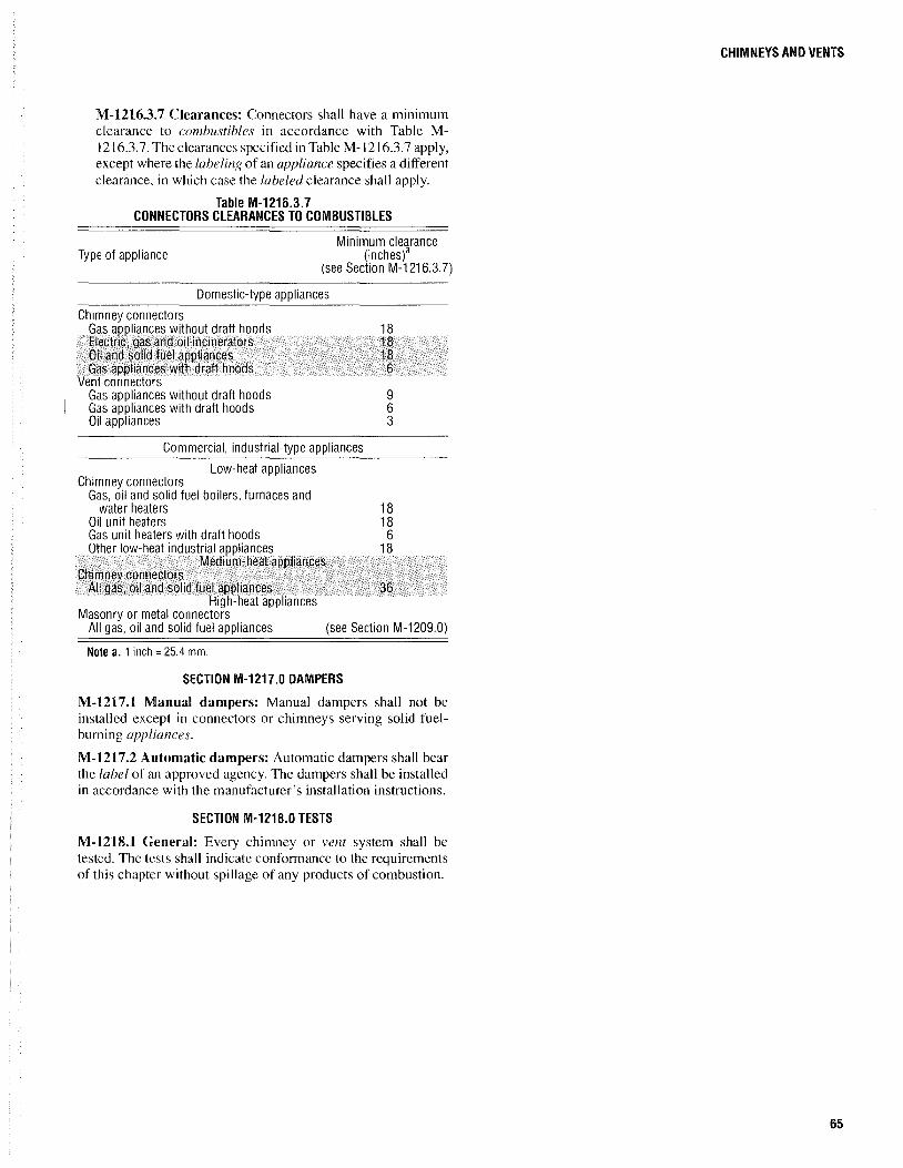
M-1216.3.7 Clearances: Connectors shall have a minimum clearance to comhustihles in accordance with Table M-1216.3.7. The clearances specified in Table M-1216.3.7 apply, except where the laheling of an appliance specifies a different clearance, in which case the laheled clearance shall apply.
Table M-1216.3.7 CONNECTORS CLEARANCES TO COMBUSTiBLES
Type of appliance Minimum clearance
(inches)a (see Section M-1216.3.7)
Domestic-type appliances
Chimney connectors Gas appliances without draft hoods Electric, gas and oil incinerators Oil and solid fuel appliances Gas appliances with draft hoods
Vent connectors Gas appliances without draft hoods Gas appliances with draft hoods Oil appliances
Commercial, industrial-type appliances
Low-heat appliances Chimney connectors
Gas, oil and solid fuel boilers, furnaces and
18 18 18 6
9 6 3
water heaters 18 Oil unit heaters 18 Gas unit heaters with draft hoods 6 Other low-heat industrial appliances 18
Medium-heat appliances Chimney connectors
All gas, oil and solid fuel appliances 36 High-heat appliances
Masonry or metal connectors All gas, oil and solid fuel appliances (see Section M-1209.0)
Note a. 1 inch = 25.4 mm.
SECTION M-1217.0 DAMPERS
M-1217.1 Manual dampers: Manual dampers shall not be installed except in connectors or chimneys serving solid fuelburning appliances.
M-l217.2 Automatic dampers: Automatic dampers shall bear the lahel of an approved agency. The dampers shall be installed in accordance with the manufacturer's installation instructions.
SECTION M-1218.0 TESTS
M-l21S.1 General: Every chimney or vent system shall be tested. The tests shall indicate conformance to the requirements of this chapter without spillage of any products of combustion.
CHIMNEYS AND VENTS
65


CHAPTER 13
MECHANICAL REFRIGERATION
SECTION M-1301.0 GENERAL
M-1301.1 Scope: This chapter shall govern the design, installation, construction and repair of refrigeration systems that vaporize and liquefy a fluid during the refrigerating cycle.
M-1301.2 Classification of refrigerants: Refrigerants shall be classified by hazard in accordance with ASHRAE 34 listed in Chapter 21. A list of typical refrigerants is contained in Appendix B.
M-1301.3 Factory-built equipment: Self-contained, factorybuilt equipment that bears the label of an approved agency shall conform to the installation requirements of Chapter 4.
SECTION M-1302.0 DEFINITIONS
M-1302.1 General: The following words and terms shall, for the purposes of this chapter and as stated elsewhere in this code, have the meanings shown herein.
Compressor: A specific machine, with or without accessories, for compressing a given refrigerant vapor.
Condenser: That part of the system designed to liquefy refrigerant vapor by removal of heat.
Evaporator: That part of the system designed to vaporize liquid refrigerant to produce refrigeration.
Fusible plug: A device having a predetermined temperature fusible member for the relief of pressure.
High-side pressure: The parts of a refrigerating system subjected to condenser pressure.
Low-side pressure: The parts of a refrigerating system subject to evaporator pressure.
Machinery room: A room in which a refrigerating system is permanently installed and operated, but not including evaporators located in a cold storage room, refrigerator box, air-cooled space or other enclosed space. Closets solely contained within, and opening only into, a machinery room shall not be considered machinery rooms but shall be considered a part of the machinery room in which said closets are contained. It is not the intent of this definition to cause the space in which a self-contained system is located to be classified as a machinery room.
Pressure-imposing element: Any device or portion of the equipment utilized for the purpose of increasing the refrigerant pressure.
Pressure-limiting device: A pressure-responsive mechanism designed to stop automatically the operation of the pressureimposing element at a predetermined pressure.
Pressure relief device: A pressure-actuated valve or rupture member designed to relieve excessive pressure automatically.
Refrigerant: A substance uti lized to produce refrigeration by its expansion or vaporization.
Refrigeration system: A combination of interconnected refrigerant-containing parts constituting one closed refrigerant circuit in which a refrigerant is circulated for the purpose of extracting heat. Direct system: A direct system is one in which the evaporator is in direct contact with the material or space refrigerated, or is located in air-circulating passages communicating with such spaces. Indirect system: An indirect system is one in which a brine cooled by the refrigerant is circulated to the material or space refrigerated or is utilized to cool the air so circulated. Indirect systems are distinguished by the type or method of application.
Stop valve: A shutoff valve for controlling the flow of liquid or gases.
SECTION M-1303.0 MAXIMUM QUANTITIES OF REFRIGERANT
M-1303.1 Group 1 refrigerants: The maximum amount of Group 1 refrigerants utilized in direct systems shall be as indicated in Table M-1303.1. The space indicated in the table shall equal the volume of the building intended to be occupied.
M-1303.1.1 Indirect systems: The amount of Group 1 refrigerants utilized in indirect systems shall not be limited.
M-1303.2 Group 2 refrigerants: The maximum amount of Group 2 refrigerants utilized in direct systems shall be 20 pounds (9 kg). Direct systems utilizing Group 2 refrigerants shall not be utilized for comfort cooling.
Exception: Direct systems, for other than comfort cooling, utilizing ammonia R-717 as the refrigerant shall not be limited in capacity where the system is designed and installed in accordance with ASHRAE 15 and llAR 2 listed in Chapter 21.
67

THE BOCA NATIONAL MECHANICAL CODE/1993
Table M-1303.1 MAXIMUM PERMISSIBLE QUANTITIES OF GROUP 1 REFRIGERANTS
FOR DIRECT SYSTEMS
Refrigerant
R-11 R-12 R-13 R-13B1 R-14 R-21 R-22 R-30 R-113 R7114 R-115 R-C318 R-500 R-502 R-744
Maximum quantity in pounds per 1,000 cubic feetb of space
intended for human occupancya
35 31 27 38 23 13 22
6 24 44 40 50 26 30 11
Nole a. Volatile charge in a control shall not be considered as refrigerant. Nole b. 1 pound per 1,000 cubic feet = 0.016 kg/m3
.
M-1303.2.1 Indirect systems: The maximum amount of Group 2 refrigerants utilized in indirect systems shall be 1,000 pounds (454 kg). All indirect systems utilizing Group 2 refrigerants shall be installed in Class T machinery rooms or outdoors.
Exception: Indirect systems utilizing ammonia R-717 as the refrigerant shall not be limited in capacity where the system is designed and installed in accordance with ASHRAE 15 and lIAR 2 listed in Chapter 21.
M-1303.3 Group 3 refrigerants: The maximum amount of Group 3 refrigerants shall be as indicated in Table M-1303.3. Group 3 refrigerants shall be exclusively utilized in laboratories or occupancies in Use Groups F, Hand S.
Table M-1303.3 MAXIMUM PERMISSIBLE QUANTITIES OF GROUP 3 REFRIGERANTS
R efrig e rant
R-170 R-290 R-600 R-601 R-1150
Group
3 3 3 3 3
Maximum quantitya, b in pounds per 1 ,000 cubic
feet of room volume
21;2 21;2 21;2 21;2 2
Nole a. The maximum Quantity shall not exceed 1,000 pounds. Nole b. 1 pound per 1,000 cubic feet = 0.016 kg/m3
; 1 pound = 0.454 kg.
M-1303.4 Alternative refrigerants: The refrigerants listed in Table M-1303.4 shall be permitted in air conditioning and refrigeration systems as substitutes for the refrigerants listed in Table M-130 1.1. The maximum quantity of such alternative refrigerants utilized in direct systems shall be in accordance with Table M-1303.4.
68
M-1303.4.1 Indirect systems: All indirect systems utilizing refrigerants R-123 or R-134a shall be installed in general machinery rooms designed and constructed in accordance with Section M-130S.0, or shall be installed outdoors.
Table M-1303.4 ALTERNATIVE REFRIGERANTS
Maximum quantitya in Refrigerant pounds per 1,000 cubic
feet of room volume
R-123 2,2-Dichloro-1, 1,1-Trifluoroethane (CF3CHCI2) .004
R-134a 1,1,1,2-Tetrafluoroethane (CHlCF3) 16
Nole a. 1 pound per 1,000 cubic feet = 0.016 kg/m3.
SECTION M-1304.0 REFRIGERATION PIPING AND EQUIPMENT
M-1304.1 Equipment: All refrigeration equipment shall be of an approved type and compatible with the type of refrigerant being utilized. The equipment shall be rated for the maximum operating pressure of the refrigeration system.
M-1304.1.1 Identification of system: A metal plate, tag or other device shall be permanently and prominently located near the refrigeration equipment indicating the type of refrigeration system, the type of refrigerant and the maximum amount of refrigerant.
M-1304.1.2 Minimum design pressure: The minimum design pressure of a refrigeration system shall be based on the type of refrigerant utilized in accordance with Table M-1304.1.2 unless otherwise approved.
Refrigerant
R-11 R-12 R-13 Rc13B1 R-14 R~21 R-22 R-30 R-40 R-113 R-114 R-115 R-123 R-134a R-170 R-290 R-C318 R-500 R-502 R-600 R-601 R·611 R-717 R-744 R-764 R-1150
TableM-1304.1.2 MINIMUM DESIGN PRESSURES
Minimum design pressures (pounds per square inch gauge)a, b
High side Low side Water or
evaporator cooled Air cooled
15 15 21 85 127 169
521 547 547 230 321 410 544 544 544 15 29 46
144 211 278 15 15 15 72 112 151 15 15 15 18 35 53
152 194 252 15 15 21 85 127 169
616 709 709 129 188 244 34 59 85
102 153 203 162 232 302 23 42 61 39 63 88 15 15 15
139 215 293 955 1,058 1,058 45 78 115
732 732 732
Nole a. Corresponding to specified saturation pressure at 14.7 psi atmospheric pressure.
Nole b. 1 pound per square inch = 6.895 kPa.

M-1304.2 Piping system: Refrigeration system piping shall conform to one of the standards listed in Table M-1304.2. The pipe shall be rated for the maximum operating pressure of the system.
Table M-1304.2 REFRIGERATING SYSTEM PIPE
Material
Copper or copper-alloy tubing Steel pipe
Standard (listed in Chapter 21 )
ASTM B88; ASTM B280 ASTM AS3; ASTM A 106
M-1304.2.1 Valves and fittings: All valves and fittings shall be of an approved type rated for the maximum operating pressure of the system.
M-1304.3 Pipe joints and connections: All joints between refrigeration system pipe or fittings shall be in accordance with one or more of the following Sections M-1304.3.1 through M-1304.3.S.
M-1304.3.1 Copper-brazed joints: All copper-joint surfaces shall be cleaned. An approved flux shall be applied where required. The joint shall be brazed with a filler metal conforming to AWS A5.8 listed in Chapter 21.
M-1304.3.2 Mechanical joints: Mechanical joints shall be installed in accordance with the manufacturer's instructions.
M-1304.3.3 Steel-threaded joints: Steel pipe threads shall conform to ASME B 1.20.1 listed in Chapter 21. Pipe-joint compound or tape shall be applied on the male threads only.
M-1304.3.4 Steel-welded joints: All steel pipe-joint surfaces shall be cleaned by approved procedures. The joint shall be welded with an approved filler metal.
M-1304.3.5 Joints between different piping materials: Joints between different piping materials shall be made with approved adapter fittings.
M-1304.4 Support: All refrigeration system equipment and piping shall be supported in an approved manner.
M-1304.S Cutting or notching: A structural member shall not be cut, notched or pierced in excess of the limitations specified in the building code I isted in Chapter 21, unless proven safe by a structural analysis.
SECTION M-1305.0 PRESSURE-LIMITING DEVICES
M-130S.1 General: Pressure-limiting devices shall be provided on all systems containing more than 20 pounds (9 kg) of refrigerant and operating above atmospheric pressure and on all water-cooled systems capable of producing a pressure in excess of the high-side design pressure.
Exception: Water-cooled units containing less than 3 pounds (1.4 kg) of a Group I refrigerant.
M-130S.2 Maximum setting: The maximum setting to which a pressure-limiting device is capable of being set by the adjusting means provided shaH not exceed 90 percent of the setting of the pressure relief device installed on the high side of a system. Where the high side of a system is not protected by a pressure relief device, the maximum setting shall not exceed the design pressure of the high side of the system, except as provided for in
MECHANICAL REFRIGERATION
Section M-130S.2.1. The pressure-limiting device shall stop the action of the pressure-imposing element at a pressure not higher than this maximum setting.
M-130S.2.1 Systems with nonposilive-displacement compressors: For systems with nonpositive-displacement compressors, the pressure-limiting device is permitted to be set at the design pressure of the high side of the system, provided that the pressure relief device is subject to the low-side pressure, and stop valves are not on the system.
M-130S.3 Pressure-limiting devices: Pressure-limiting devices shall be connected between the pressure-imposing element and any stop valve on the discharge side without intervening stop valves in the line leading to the pressure-limiting device.
SECTION M-1306.0 PRESSURE RElIEF PROTECTION
M-1306.1 General: Every refrigeration system shall be protected by a pressure relief device.
M-1306.2 Pressure relief device: All pressure relief devices shall bear the label of an approved agency. The device shall be rated for the capacity of the refrigeration system. The pressure relief device shall be set at the maximum design pressure of the system or equipment.
M-1306.2.1 Discharge piping: Pressure relief devices and fusible plugs serving the following systems shall discharge to the atmosphere at a location not less than 15 feet (4572 mm) above the adjoining ground level and not less than 20 feet (6096 mm) from any window, ventilation opening or exit in any building.
I. Any system containing a Group 3 refrigerant. 2. Any system containing more than 6 pounds (2.72 kg)
of a Group 2 refrigerant. 3. Any system containing more than 100 pounds (45.36
kg) of a Group I refrigerant.
Discharge piping connected to the discharge side of a fusible plug or rupture member shall have provisions to prevent plugging of the piping in the event that the fusible plug or rupture member functions.
M-1306.2.2 Sizing: Discharge piping shall be sized for simultaneous relief of the maximum quantity of refrigerant in the system, via the sum of the system's pressure rei ief devices and in accordance with the manufacturer's instructions. Where relief piping for more than one system is interconnected, such relief piping shall be sized for the largest system. Systems utilizing different classifications of refrigerant shall not have discharge piping interconnected.
M-1306.2.3 Optional ammonia discharge: Where ammonia is utilized, the preferred discharge is into the atmosphere. Alternatively, the ammonia shall discharge into a tank of water which shall not be utilized for any other purpose except ammonia absorption.
M-1306.2.3.1 Tank water: At least I gallon (0.004 m3) of
fresh water shall be provided for each pound (0.0083 m3/kg) of ammonia in the system. Such water shall be prevented from freezing without the utilization of salt or chemicals.
69

THE BOCA NATIONAL MECHANICAL CODE/1993
M-1306.2.3.2 Tank construction: The tank shall be substantially constructed of iron or steel not less than 0.12Sinch (3.2 mm) in thickness or No. II US Gage. The tank shall have a hinged cover or, if of the enclosed type, the tank shall have a vent hole at the top.
M-1306.2.3.3 Piping connections: All piping connections shall be through the top of the tank only. The discharge pipe from the pressure relief valves shall discharge the ammonia into the center of the tank near the bottom.
M-1306.2.4 Discharge of sulfur dioxide: The point of discharge of sulfur dioxide R-764 shall be to a tank of sodium dichromate brine. The minimum quantity of brine shall equal I gallon (0.004 m3) for each pound (0.0083 m3Jkg) of sulfur dioxide refrigerant in the system. The minimum concentration of brine shall be 21a pounds of dichromate for each 1 gallon (300 kg/m3) of water.
M-1306.3 Location: Pressure relief devices shall be located to relieve pressure of all piping and equipment when valves or pumps are in a closed position.
SECTION M-1307.0 CLASS T MACHINERY ROOMS
M-1307.1 Room enclosure: Class T machinery rooms shall be separated from the remainder of the building by a minimum I-hour fire separation assembly. All doors shall be tight fitting. Every door shall be clearly labeled "Machinery Room."
M -1307.2 Emergency controls: Emergency controls capable of shutting down all of the refrigeration equipment shall be located outside Class T machinery rooms near the room entrance.
M-1307.3 Exhaust system: An independent mechanical exhaust system shall be provided for each Class T machinery room. The exhaust system shall operate when the refrigeration system is turned on. The exhaust system shall provide a minimum of six air changes per hour.
SECTION M-130B.0 GENERAL MACHINERY ROOMS
M-130S.1 General: General machinery rooms containing air conditioning and refrigeration equipment utilizing refrigerants R-123 or R-134a shall comply with Sections M-1308.1.1 through M-1308.1.7.
70
M-130S.1.1 Design: General machinery rooms shall be designed and constructed in accordance with ASHRAE IS listed in Chapter 21.
M-130S.1.2 Ventilation: All general machinery rooms shall be provided with mechanical ventilation in accordance with ASHRAE IS listed in Chapter 2l.
M-130S.1.3 Detection and alarm: Where refrigerant R-123 is utilized, the general machinery room shall be equipped with an approved compound-specific refrigerant detection system that will sound an alarm when the refrigerant R-123 concentration in the room reaches the allowable exposure limit (AEL) of IO parts per million.
M-130S.1.4 Oxygen monitoring: Where refrigerant R-134a is utilized, the general machinery room shall be equipped with an approved oxygen-sensing system that will sound an alarm
when the oxygen level in the room falls below 19.5 percent of the room air volume.
M-130S.1.S Access: Access to the general machinery room or rooms shall be restricted to authorized personnel.
M-130S.1.6 Self-contained breathing apparatus: At least one self-contained breathing apparatus shall be provided and located outside of the general machinery room, near the room entrance.
M-130S.1.7 Discharge piping: Pressure relief devices, fusible plugs and purge systems shall discharge to the outside atmosphere at a location not less than IS feet above the adjoining ground level and not less than 20 feet from any window, ventilation opening, air intake opening or exit opening in any building. Discharge piping shall be designed and constructed in accordance with ASHRAE IS listed in Chapter 21.
SECTION M-1309.0 TESTS
M-1309.1 General: All mechanical refrigeration systems, other than factory-assembled parts that have been tested in the factory, shall be tested to the maximum operating pressure of the system. The tests shall be conducted utilizing air or an inert gas.

CHAPTER 14
FIREPLACES, SOLID FUEL-BURNING AND GAS ACCESSORY APPLIANCES
SECTION M-1401.0 GENERAL
M-1401.1 Scope: This chapter shall govern the design, installation, construction and repair of fireplaces, solid fuel-burning appliances and decorative gas appliances accessory to fireplaces. Crematories and incinerators shall comply with the provisions of Chapter 15.
M-1401.2 Hazardous locations: Fireplaces, solid fuel-burning appliances and decorative gas appliances accessory to fireplaces shall not be installed in hazardous locations.
SECTION M-1402.0 ROOM HEATERS
M-1402.1 General: Solid fuel-burning room heaters shall be tested in accordance with UL 1482 listed in Chapter 21.
SECTION M-1403.0 FACTORY-BUILT FIREPLACES
M-1403.1 General: Factory-built fireplaces shall be tested in accordance with UL 127 listed in Chapter 21. Fireplace stoves shall be tested in accordance with UL 737 listed in Chapter 21.
SECTION M-1404.0 MASONRY FIREPLACES
M-1404.1 Dimensions: The firebox of a masonry fireplace shall have a minimum depth of 20 inches (508 mm). The size of the chimney connection shall be a minimum cross-sectional area of 50 square inches (32258 mm2). The minimum cross-sectional area of the fireplace shall equal the cross-sectional area of the chimney connection.
M-1404.1.1 Rumford fireplaces: Rumford fireplaces shall be permitted provided that the depth of the fireplace is at least 12 inches (305 mm) and is at least one-third of the width of the fireplace opening; and that the throat is at least 12 inches (305 mm) above the lintel, and is at least l/20th the cross-sectional area of the fireplace opening.
M-1404.2 Wall construction: Fireplace walls lined with a minimum of 2 inches of approved low-duty refractory brick shall have a minimum total thickness of 8 inches (203 mm) of solid masonry. Approved medium-duty fire-clay mortar or an equivalent shall be utilized with the low-duty refractory brick. Unlined fireplace walls shall be constructed of solid masonry having a minimum total thickness of 12 inches (305 mm).
M-1404.2.1 Extension of liners: The liner of the fireplace walls shall extend a minimum of 4 inches (102 mm) into the throat of the fireplace.
M-1404.2.2 Throat and smoke chamber: The walls of the throat and smoke chamber shall be constructed of solid masonry having a minimum total thickness of 8 inches (203 mm). The throat and smoke chamber walls are permitted to be reduced in thickness to 4 inches of solid masonry provided that such walls are lined with at least I inch of insulating refractory masonry so that the heat transferred through this wall is not more than the heat transferred through 8 inches (203 mm) of solid masonry.
M-1404.2.3 Heat exchangers: Gravity-fed heat exchangers installed in the walls of masonry fireplaces shall not reduce the total thickness of solid masonry.
M-1404.3 Foundation and hearth: The foundation of a fireplace shall be constructed of noncomhustihle material and shall conform to the requirements of the building code listed in Chapter 21. The hearth and hearth extension shall be constructed of solid masonry having a minimum thickness of 4 inches (102 mm).
M-1404.3.1 Hearth extension: The hearth shall extend a minimum of 16 inches (406 mm) beyond the face of the fireplace opening and a minimum of 8 inches (2m mm) on each side of the fireplace opening for fireplaces having an opening of less than 6 square feet (0.56 m2
). The hearth of larger-sized fireplaces shall extend a minimum of 20 inches (508 mm) beyond the face of the fireplace opening and a minimum of 12 inches (305 mm) on each side ol"the fireplace opening. Comhustihle forms utilized during the construction of the hearth and hearth extension shall be removed.
M-1404.4 Clearance to combustibles: The exterior surface of fireplace walls shall have a minimum clearance of4 inches (102 mm) to comhustihle materials. Comhustihle material, including framing and sheathing, shall have a minimum clearance of 2 inches (51 mm) from the exterior surface of smoke chamber walls. Comhustihle material attached to a fireplace face, such as trim and mantels, shall have a minimum clearance of 6 inches (152 mm) from a fireplace opening. Comhustihle material above and projecting more than I Y2 inches (38 mm) from a fireplacc face shall have a minimum clearance of 12 inches (30S mm) above a fireplace opening.
M-1404.S Opening to the chimney: Means shall be provided to shut off the opening to the chimney when the fireplace is not in operation.
71

THE BOCA NATIONAL MECHANICAL CODE/1993
M-1404.S.1 Dampers: Dampers shall be constructed of metal having a minimum thickness of No. 12 Manufacturers Standard Gage (0.105 inch).
M-1404.6 Chimneys with metal hoods: Metal hoods shall extend a minimum of6 inches (152 mm) beyond the firebox. The hoods shall comply with the requirements for metal chimneys.
M-1404.7 Existing masonry chimneys: Existing masonry chimneys are permitted to vent open fireplaces only - even if the existing chimneys lack the clearances to comhustihles as required by Section M-1207.4 - provided that such chimneys otherwise meet the requirements of Chapter 12 of this code or are made to conform to such requirements through repair or relining.
SECTION M-1405.0 BARBECUE PITS
M-140S.1 Wall construction: Barbecue pit walls lined with a minimum of 2 inches (51 mm) of approved low-duty refractory brick shall have a minimum total thickness of 8 inches (203 mm) of solid masonry. Approved medium-duty fire-clay mortar or an equivalent shall be utilized with the low-duty refractory brick. Unlined barbecue pit walls shall be constructed of solid masonry having a minimum total thickness of 12 inches (305 mm).
M-140S.2 Foundation: The foundation of a barbecue pit shall be constructed of noncomhustihle material and shall conform to the requirements of the building code listed in Chapter 21.
M-140S.3 Clearance to combustibles: The exterior walls of a barbecue pit shall have a minimum clearance of 4 inches (102 mm) to comhustihle materials.
M-140S.4 Kitchen exhaust and suppression: A commercial kitchen exhaust system shall be installed in accordance with Chapter 5. The suppression system for the kitchen exhaust system shall be designed and approved for barbecue pits.
SECTION M-1406.0 GAS ACCESSORIES
M-1406.1 Labeled: Gas-burning appliances designed for installation in approved fireplaces, such as decorative gas appliances, shall bear the lahel of an approved agency and shall be installed in accordance with the manufacturer's instructions for the laheled equipment.
M-1406.2 Flame safeguard device: Gas appliances installed in fireplaces shall have the main burner ignition by means of a direct ignition device, an ignitor or a pilot flame to ignite the fuel at the main burner, and shall be equipped with a flame safeguard device. The flame safeguard device shall automatically shut off the fuel supply to a main burner or group of burners when the means of ignition of such burners becomes inoperative.
M-1406.3 Fixed dampers: Manual fireplace dampers are required to be fixed in a manner that maintains the gas appliance manufacturer's required minimum permanent vent opening at all times.
72

CHAPTER 15
INCINERATORS AND CREMATORIES
SECTION M-1501.0 GENERAL
M-1S01.1 Scope: This chapter shall govern the installation, repair, maintenance and approval of all incinerators and crematories.
M-1501.2 Annual inspection: All crematories and all incinerators, except Class 1, Class lA and domestic incinerators, shall be inspected annually by the code official.
M-1501.3 Prohibited locations: Installation of any type of incinerator in garages or in areas containing explosive orflammabie liquids or fumes shall be prohibited.
M-lS01.4 Factory-built incinerators and crematories: Factory-built incinerators and crematories shall conform to the requirements of Chapter 4.
SECTION M-1502.0 DEFINITIONS
M-lS02.1 General: The following words and terms shall, for the purposes of this chapter and as stated elsewhere in this code, have the meanings shown herein.
Auxiliary fuel-firing equipment (incinerator): Equipment to supply additional heat, by the combustion of an auxiliary fuel, for the purpose of attaining temperatures that are sufficiently high enough to:
1. Dry and ignite waste material; 2. Maintain ignition thereof; and 3. Promote complete combustion of combustible solids,
vapors and gases.
Curtain wall (incinerator): A partition wall between chambers under which pass the products of combustion.
Damper, barometric: A device to admit air to the breeching or flue connection, thereby automatically maintaining a constant draft in the equipment.
Damper, guillotine: An adjustable blade installed vertically in a breeching or flue connection, counterbalanced for easy operation.
Damper, sliding: An adjustable blade installed in a duct, breeching or flue connection.
Downpass: A gas passage placed between two chambers of an incinerator to carry the products of combustion in a downward direction.
Excess air: The air remaining after a fuel has been completely burned, or that air supplied in addition to the theoretical quantity required for combustion.
Flue connection (breeching): A passage for conducting the products of combustion from a fuel-fired appliance to the vent or chimney.
Flue gases: Products of combustion and excess air.
Incinerator, domestic gas-fired type: An approved, directly fed, gas-fired-type incinerator for the burning of ordinary waste material, having a capacity of not more than 5 cubic feet (0.14 mJ), generally located within a structure, and designed primarily for utilization in one- and two-family dwellings.
Primary air: Any air which is mixed with the fuel at or in the burner or fuel bed for the purpose of promoting combustion of the fuel or combustible materials.
Secondary air: Any air brought in around the burner or through openings in the combustion chamber for the purpose of completing combustion.
Theoretical air: The exact amount of air required to supply oxygen for complete combustion of a given quantity of a specific fuel.
Underfire air: Any air controlled with respect to quantity and direction, forced or induced, supplied beneath the grate that passes through the fuel bed.
SECTION M-1503.0 WASTE CLASSIFICATION
M-lS03.1 Waste analysis: The basis for satisfactory incinerator operation is the proper analysis of the waste to be destroyed, and the selection of proper equipment to best destroy that particular waste. For the purposes of this chapter, all types of waste to be destroyed shall be classified as indicated in Sections M-1503.2 through M-1503.9 and Table M-1503.1.
M-1503.2 Type 00 waste: Type 00 waste is trash, consisting of a mixture of highly combustible waste such as paper, paper products, cardboard, cartons, wood boxes and comhustihle floor sweepings from commercial and industrial activities. The mixture contains up to 10 percent by weight of plastic bags, coated paper, laminated paper, treated corrugated cardboard, oily rags and plastic or rubber scrap. This type of waste contains up to 10 percent moisture, 5 percent noncombustible solids, has a bulk density of less than 8 pounds per cubic foot ( 128 kg/mJ) and has a heating value of 8,500 British thermal units (Btu) per pound (1.98 x 10⁷ J/kg) as fired.
73

THE BOCA NATIONAL MECHANICAL CODE/1993
Table M-1503.1 CLASSIFICATION DF WASTES TO BE INCINERATED
Mininum Btue of Btuhe burner
Type of waste Approximate Btue auxiliary fuel input per Moisture Noncombustible per pound of pound waste
Principal components composition content solids value/pound waste to be primary percent by weight (percent) (percent) of refuse as included in chamber and density firedd combustion unless
Type Description calcu lationsd otherwise specifiedd
Combustible waste, Waste containing paper, paper products, less than 10% cartons, rags, wood plastic or
00 scraps, floor rubber scrap sweepings; with Density of 00 trash 0
and Trash domestic, commercial less than 8 10 5 8,500 0 (see Section and industrial sources pounds per cubic The mixture contains up foot, and 0 trash M-1509.4)
oa to 1 O-percent plastic 8 to 10 pounds bags, coated or treated per cubic foot paper products, and rubber or plastic scrapb
Combustible waste, Rubbish 100% paper, paper products, Garbage up to 20% cartons, rags, wood Density 8 to 10 0
1" Rubbish scraps, floor pounds per cubic 25 10 6,500 0 (see Section sweepings; with foot M-1509.4) domestic, commercial and industrial sources
Rubbish and garbage; Rubbish 50% residential sources Garbage 50% 1,500
2a Refuse Density 15 to 20 50 7 4,300 0 (see Section pounds per cubic M-1509.4) foot
Animal and vegetable Garbage 100% wastes; restau rants, Rubbish up to 35%
3a Garbage hotels, markets, Density 30 to 35 70 5 2,500 1,500 3,000 institutional, pounds per cubic commercial and club foot sources
Carcasses, organs, solid 100% animal and Animal organic wastes; human tissue 5,000 4 solids and hospital, laboratory, Density 45 to 55 85 5 1,000 3,000 Primary
organic abattoirs, animal pounds per cubic 3,000 wastes pounds and similar foot Secondary
sources
Gaseous I ndustrial process wastes Dependent Variable Variable Variable liquid or on Variable according to according to accordi ng to 5 semi- Variable according to liquid predominant wastes survey wastes wastes wastes
wastes components survey survey survey
Semisolid Combustibles requiring Dependent Variable Variable Variable Variable 6 and solid hearth, retort or Variable on according to according to according to according to
wastes grate-burning predominant wastes survey wastes wastes wastes equipment components survey survey survey
Note a. The above figures on mOisture content, ash and British thermal units as fired have been determined by analysis of many samples to compute heat release, burning rate, velocity and other details of incinerator design. Any design based on these calculations accommodates minor variations.
Note b. Where trash composition is such that any single charge to the incinerator will contain more than 10-percent plastic or rubber scrap by weight, the waste shall be classified as Type 6 waste.
Note c. Btu = British thermal units; Btuh = British thermal units per hour. Note d. 1 Btu per pound = 2.329 J/kg.
74

M-lS03.3 Type 0 waste: Type 0 waste is trash, consisting of a mixture of highly combustible waste such as paper, paper products, cardboard, cartons, wood boxes and combustible floor sweepings from commercial and industrial activities. The mixtures contain up to 10 percent by weight of plastic bags, coated paper, laminated paper, treated corrugated cardboard, oily rags and plastic or rubber scrap. This type of waste contains up to to percent moisture, 5 percent noncombustible solids, has a bulk density of8 to 10 pounds per cubic foot (128 to 160 kg/m') and has a heating value of 8,500 Btu per pound (1.98 x 10⁷ J/kg) as fired.
M-lS03.4 Type 1 waste: Type 1 waste is rubbish, consisting of combustible waste such as paper, paper products, cartons, rags, wood scraps, sawdust, foliage and floor sweepings from domestic, commercial and industrial activities. This type of waste contains up to 25 percent moisture, up to 10 percent noncombustible solids, has a bulk density of 8 to 10 pounds per cubic foot (128 to 160 kg/m3) and has a heating value of 6,500 Btu per pound (1.51 x 10⁷ J/kg) as fired.
M-lS03.S Type 2 waste: Type 2 waste is refuse consisting of an approximately even mixture of rubbish and garbage by weight. This type of waste consists of up to 50 percent moisture, 7 percent noncombustible solids, has a bulk density of 15 to 20 pounds per cubic foot (240 to 320 kg/m3) and has a heating value of 4,300 Btu per pound (1.00 x 10⁷ J/kg) as fired.
M-lS03.6 Type 3 waste: Type 3 waste is garbage consisting of animal and vegetable wastes. This type of waste contains up to 70 percent moisture, up to 5 percent noncombustible solids, has a bulk density of 30 to 35 pounds per cubic foot (480 to 520 kg/m3
) and has a heating value of 2,500 Btu per pound (0.58 x 10⁷ ]!kg) as fired.
M-lS03.7 Type 4 waste: Type 4 waste is human parts and animal remains consisting of carcasses, organs and solid organic wastes. This type of waste contains up to 85 percent moisture, 5 percent noncombustible solids, has a bulk density of 45 to 55 pounds per cubic foot (720 to 817 kg/m') and has a heating value of 1,000 Btu per pound (0.23 x 10⁷ J!kg) as fired.
M-lS03.8 Type 5 waste: Type 5 waste is byproduct waste, gaseous, liquid or semiliquid, such as tar, paints, solvents, sludge, fumes and similar materials. Btu values shall be determined for the individual materials to be incinerated.
M-lS03.9 Type 6 waste: Type 6 waste is solid byproduct waste, such as rubber, plastics, wood waste and similar materials. Btu values shall be determined for the individual materials to be incinerated.
SECTION M-1504.0 INCINERATOR CLASSIFICATION
M-lS04.1 Classification: Incinerators shall be classified in accordance with Sections M-1504.2 through M-1504.9. Section M-ISOS.3 shall apply to incinerators designed to bum a combination of wastes not included in the classification provided for herein.
M-lS04.2 Class I: Class I shall include portable, packaged or job-assembled direct-fed incinerators of 5 cubic feet (0.14 m') storage capacity, or 25 pounds per hour (31.5 x 10⁻⁴ kg/s) burning rate, for Type 1 or Type 2 waste.
INCINERATORS AND CREMATORIES
M-1504.3 Class IA: Class IA shall include portable, packaged or job-assembled direct-fed incinerators of 5 to 15 cubic feet (0.14 to 0.42 m3) primary chamber volume of up to, but not including, 100 pounds per hour (126 x 10-4 kg/s) burning rate, for Type 1 or Type 2 waste.
M-lS04.4 Class IIA: Class IlA shall include flue-fed incinerators served by two flues, one for charging waste and one for carrying the products of combustion.
M-1504.S Class III: Class III shall include direct-fed incinerators with a burning rate of 100 pounds per hour ( 126 x 10-4 kg/s) or over, for Type 00, Type 0, Type I or Type 2 waste.
M-1504.6 Class IV: Class IV shall include direct-fed incinerators with a burning rate of 75 pounds per hour (94.5 x 10⁻⁴ kg/s) or over, for Type 3 waste.
M-lS04.7 Class V: Class V shall include municipal incinerators.
M-lS04.8 Class VI: Class VI shall include crematory and pathological incinerators, for Type 4 waste.
M-lS04.9 Class VII: Class VII shall include incinerators designed for specific byproduct wastes, for Type 5 or Type 6 waste.
SECTION M-1505.0 DESIGN
M-lSOS.l Design requirements: Incinerators shall be designed in accordance with the requirements of Sections M-1505.2 through M-1505.17.
M-lSOS.2 Incinerator volume: The interior incinerator volume shall be calculated by measuring the inside distance between the side walls, and from the front end to the rear wall and from paving to roof, excluding ash pit, interior walls, grates and hearth. Door openings, chutes or charging hoods or flue connections shall not be considered a part of the incinerator volume. The volume of the charging door opening, through which the refuse is placed in the incinerator, shall be considered a part of the incinerator volume.
M-lSOS.2.1 Roof height: Roof height above the grate shall not be less than four-thirds of the grate area to the power of four-elevenths (0/, AG4/11) plus or minus 10 percent, except Class VI incinerators.
M-lS0S.2.2 Heat release: Total heat release in the entire incinerator shall not exceed 25,000 British thermal units per hour (Btuh) per cubic foot (258 kW/m3).
M-lSOS.3 Incinerator for combination waste: Any incinerator which is designed to burn a combination of wastes and where such combination does not fall into a category of "Incinerator classification" as set forth in Section M-1504.0, shall be classified as Class VI or Class VII. In the design, the specific wastes shall be classified into the standard categories for such wastes, and the portion of the incinerator chamber burning such waste shall conform to the minimum and maximum requirements set forth for that category. The total products of combustion and the total heat release and burner capacities shall be utilized in determining the sizes of the down pass, final combustion chamber, flue connection and stack.
75

THE BOCA NATIONAL MECHANICAL CODE/1993
M-lS0S.4 Secondary burners: All new incinerators shall provide for a secondary burner or burners (see Section M-1509.4). Primary burners shall be provided as required in Table M-1503.1.
M-lS0S.S Settling chamber: A chamber shall be provided in which the products of combustion are reduced in velocity to 9 feet per second (2.7 m/s) at 1,400 degrees F. (760 degrees C.) while traveling in a vertical direction. The length of gas travel at 9 feet per second (2.7 m/s) shall be a distance at least the square root of the horizontal cross-sectional area of the settling chamber, measured from the top of the opening under the curtain wall to the roof of the incinerator, or to the top of the breeching connection, whichever is lower.
M-lS0S.6 Flame port: The flame port shall be designed to provide a velocity of not less than 50 feet per second (15.2 m/s) calculated at 1,000 degrees F. (538 degrees C.).
Exception: This requirement shall not apply to Class I and Class IA domestic gas-fired incinerators.
M-lS0S.7 Downpass: All incinerators, except gas-fired domestic, shall include a down pass or other means of creating turbulence for the gases of combustion to assure thorough mixing of the gases prior to their entering the secondary combustion chamber.
M-lS0S.8 Refractory lining: A refractory lining that is 4V2 inches (114 mm) in thickness shall be required except where the area of any wall exceeds 35 square feet (3.22 m2). Every wall over 4 feet (1219 mm) in height shall be anchored every 4 feet (1219 mm). eastable or plastic refractory shall be anchored every 18 inches (457 mm).
120 115 110 105 100
95 90 85 80 75 70 65 60 55 50 45 40 35 30
--.......
..... I..--""" ...... ,.
f-'
M-lS0S.S.1 Exceeded area: Where the area specified in Section M-1505.8 is exceeded, the lining of all walls and the roof shall be at least 9 inches (228 mm) in thickness.
M-lSOS.8.2 Approval: Walls of greater thicknesses shall be provided where required to provide structural stability.
M-lSOS.9 Roofs, arches and lintels: All roofs or arches shall be designed so that metal supports or lintels are not directly exposed to heat or flame.
M-lS0S.10 Barometric damper: A barometric damper shall be provided, and for natural draft stacks, the free area ofthe damper shall be at least the percentage of the cross-sectional area of the flue connections, breeching or stack in which the damper is located as indicated in Figure M-1505.10.
M-lSOS.U Dampers: All incinerators shall be provided with a guillotine or sliding damper. Design criteria shall provide at least lO-percent free opening when the damper is in the fully closed position.
M-lS0S.U.l Damper construction: The dampers shall be constructed of steel frames with refractory lining or of alloy steel to withstand the high temperature. Guillotine dampers provided for draft regulation shall be counterbalanced.
M-lS0S.U.2 Damper box: All guillotine and sliding dampers shall be provided with a damper box to house completely the damper when in its full open position. The damper box shall be constructed of steel having a minimum nominal thickness of 0.105 inch (No. 12 Manufacturers Standard Gage).
M-lS0S.U.3 Locking: All guillotine and sliding dampers shall be provided with an approved locking device.
,.. i.-""'"
....... ,.. ........
20 30 40 50 60 70 SO 90 100 110 120 130
76
HEIGHT a OF CHIMNEY (OR STACK) ABOVE BASE OF THE INCINERATOR
NOTE o. 1 FOOT = 304.Smm
Figure M-1505.10 DETERMINATION OF BAROMETRIC DAMPER fREE AREA
(For natural draft stacks only)

M-lSOS.12 Mortar: All refractory brick shall be laid in an approved high-temperature, air-setting refractory mortar. Such mortar shall be for the same service as the refractory brick.
M-lSOS.13 Metal casing: A metal casing shall be required for all incinerators.
M-lSOS.14 Insulation: Insulation shall not be less than 2 inches (51 mm) in thickness, and shall provide a shell temperature not in excess of 90 degrees F. (32 degrees C.) after the incinerator is fired for the maximum normal operation time. The shell temperature shall not exceed a temperature of 180 degrees F. (82 degrees C.).
M-lSOS.lS Refuse charging: Refuse charging shall be direct, side, end or top. The charging chutes shall not exceed 6 feet (1829 mm) in length measured from the floor opening above the incinerator to the outside roof of the incinerator. The charging chute shall be constructed of steel casing having a minimum thickness of 0.105 inch (No. 12 Manufacturers Standard Gage), lined with at least 4 V2 inches (114 mm) of refractory. Where the incinerator is top charged, an induced draft fan shall be provided.
M-lSOS.16 Combustion air: Air for combustion shall be calculated at 15 pounds (6.5 kg) for 10,000 British thermal units (Btu) (10.5 kJ) total heat release, based on the theoretical air required for complete combustion of liquid and solid fuels of 7 pounds air (3.17 kg) to 7 1h pounds air (3.40 kg) per 10,000 Btu (10.5 kJ) in such fuels.
M-lSOS.17 Underfire air: Underfire air shall not exceed 10 percent of the total air.
SECTION M-150S.0 CONSTRUCTION
M-lS06.1 Materials: High-temperature block insulation shall be required for its high-insulating qualities and resistance to deformation under high temperature. High-heat-duty refractory brick shall be required for its resistive qualities to temperature, spalling, abrasion and disintegration.
M-lS06.2 High-temperature block: The high-temperature block insulation required by this chapter shall meet ASTM C612, Class 2, listed in Chapter 21.
M-lS06.3 Refractory brick: The high-heat-duty refractory brick required by this chapter shall be an approved material.
M-lS06.4 Hydraulic setting castable refractory: The hydraulic setting castable refractory required by this chapter shall be an approved material.
M-lS06.4.1 Installation: All castable refractory walls shall be installed to form a monolithic structure and shall be anchored to the exterior shell ofthe incinerator. Arches of the suspended type shall be constructed so that their weight is not supported by refractory walls. Alloy steel or refractory anchors shall be spaced not more than 18 inches (457 mm) horizontally and vertically and in accordance with the refractory manufacturer's instructions.
SECTION M-1507.0 COMMERCIAL AND INDUSTRIAL INCINERATORS
M-lS07.1 General: Commercial and industrial incinerators shall conform to the requirements of Sections M-1507.1.1 through M -1507.1.6.
INCINERATORS AND CREMATORIES
M-lS07.1.1 Location: Inside incinerators and waste material bins or containers shall be located either in a room or compartment not utilized for any other purpose or in a boiler room. The room shall be enclosed by a I-hour fireresistance rated assembly but not less than the fireresistance rating required by the building code I isted in Chapter 21. Openings between a high-hazard occupancy and an incinerator room shall not be permitted.
M-lS07.1.2 Fire suppression system: Every incinerator room shall be provided with an approved automatic fire suppression system installed in accordance with the building code listed in Chapter 21.
Exception: This requirement shall not apply to rooms where the incinerator bums only Type 4 waste.
M-lS07.1.3 Operating instructions: The incinerator operator shall follow the written instructions of the manufacturer. One copy of the instructions shall be furnished to the code official, and one copy shall be protected from soiling and posted in the incinerator room.
M-lS07.1.4 Nameplate: A nameplate shall be conspicuously fastened to the incinerator indicating the manufacturer's name, model number, rated capacity of the unit, the type of waste for which the incinerator is designed and the date of installation.
M-lS07.l.S Scrubbers: Alkaline scrubbers, or other approved devices, shall be required for incinerators that bum halogenated compounds.
M-lS07.1.6 Prohibited installations: In-line incinerators with a burning capacity less than 750 pounds (340 kg) per hour shall not be installed.
SECTION M-150B.O REQUIREMENTS BY CLASS OF INCINERATOR
M-lS0S.l General: The requirements of Sections M-1508.2 through M-1508.9 apply in addition to the requirements of Section M-1504.0.
M-lSOS.2 Class I: Class I incinerators are for Type I or Type 2 waste.
M-lSOS.2.1 Shell temperature: Class I incinerators shall have a sufficient thickness of refractory lining and insulation to prevent the shell temperature from exceeding 100 degrees F. (38 degrees C.) above normal room temperature, but shall not exceed 180 degrees F. (82 degrees C.). Provisions shall be made for expansion to reduce or eliminate damage to the incinerator.
M-lSOS.2.2 Internal temperature: Class I incinerators shall be constructed to withstand intermittent internal temperatures of 1,800 degrees F. (982 degrees C.) without failure of structural parts, such as cracking or warping, so as to permit flame passage or emission of combustion gases or sparks to the exterior.
M-lSOS.3 Class IA: Class IA incinerators are for Type I or Type 2 waste.
M-lSOS.3.1 Shell temperature: The design shall be such that when the incinerator is fired with normal waste to be burned at the rated capacity of the incinerator (in pounds per hour of Type 1 or Type 2 waste), the shell temperature at any point
77

THE BOCA NATIONAL MECHANICAL CODE/1993
shall not exceed ISO degrees F. (S2 degrees C.). This maximum temperature shall not apply at the surface of the doors and frames and at the breeching outlet. The incinerator shall be constructed of steel exterior casing having a minimum thickness of 0.060 inch (No. 16 Manufacturers Standard Gage), a I-inch thickness of high-temperature block insulation, and a 21,Q-inch thickness of high-heat-duty firebrick or a 2 V2-inch thickness of castable or plastic refractory. The castable or plastic refractory shall be anchored to the exterior steel casing in an approved manner.
M-ISOS.3.2 Internal temperatures: The incinerator shall be constructed to withstand intermittent internal temperatures of I ,SSO degrees F. (1027 degrees C.) without failure of structural parts, such as cracking or warping, so as to permit flame passage or emission of combustion gases or sparks to the exterior.
M-lSOS.4 Class nA: Class IIA incinerators are for Type 1 or Type 2 waste fed in small compact packages from two or more floors above the incinerator. This class of incinerator shall be provided with automatic sequence of operation.
78
M-lSOS.4.1 Flues: Class IIA incinerators shall be served by two flues, one for charging waste and one for carrying the products of combustion. A positive method shall be employed to prevent smoke and fumes from escaping into the charging flue, and provisions shall be made to ensure that the charging flue remains free from vermin and odor.
M-lSOS.4.2 Burning area: The minimum burning area shall be 0.10 square feet (0.0093 m2) per sleeping room and combustion calculations shall be based on 3 hours burning per day. Where the burning area consists of a combination drying hearth and cast-iron grate, the hearth area shall not exceed SO percent of the total burning area.
M-lSOS.4.3 Shell temperature: The primary chamber shall have a volume of at least 4 cubic feet per square foot (1.22 m'/m2) of burning area. The shell temperature shall not exceed 90 degrees F. (32 degrees C.) above normal room temperature, and shall not exceed ISO degrees F. (S2 degrees C.).
M-lSOS.4.4 Combustion air: Primary (underfire), secondary and overfire air shall be provided through adjustable openings to meet the minimum requirements as set forth in Section M-JSOS.17.
M-lSOS.4.S Service opening: Service openings at each floor shall not have a daylight opening that exceeds one-third the cross-sectional area of the charging flue. The daylight opening shall not exceed 160 square inches (0.103 m2
). Such service opening or other charging device shall be designed without projection into the flue and with the opening to the flue interior closed off while the service opening door is fully open. This door shall close automatically upon release.
M-lSOS.4.6 Refractory lining: Refractory lining of the incinerators shall meet the requirements of Section M-ISOS.S.
M-lSOS.4.7 Gas velocities and emissions: Incinerators under this class shall contain a system to control gas velocities and emissions. This system shall include secondary combustion chambers, burners, settling chambers and gas washers or scrubbers.
M-lSOS.S Class In: Class III incinerators are for Type 1 or Type 2 waste.
M-lSOS.S.l Type 1 waste: Where designed to burn Type 1 waste, the incinerator shall contain cast-iron grates, stationary or dump, or a combination thereof with air openings of at least 40 percent of the total burning area. In lieu of 100 percent of the grate area, up to 20 percent of the total burning area shall be solid hearth.
M-lS0S.S.2 Type 2 waste: Where designed to burn Type 2 waste, the incinerator shall contain a combination drying hearth and cast-iron grate area, each approximately SO percent of the total burning area. Where step grates or sloping grates are utilized in lieu of the hearth, such grates shall provide at least SO percent of the grate surface.
M-lSOS.S.3 Burning rate: Maximum burning rate per square foot of primary area shall be as indicated in Table M-ISOS.S.3. The areas of grate and hearth shall be calculated on a horizontal projected area and not on the line of the slope or the area of individual steps.
Table M-1508.5.3 MAXIMUM BURNING RATE VARIOUS TYPE WASTES
Burning rate
Capacity (pounds per square foot per hourb)
(pounds Logarithm Types 00, 0, Type 3 Type 4 per hourb) 1 and 2 waste, waste, no waste, factor 8 factor factor 10
100 2.00 20 16 10 200 2.30 23 18 12a
300 2.48 25 20 14a
400 2.60 26 21 15a
500 2.70 27 22 16a
600 2.78 28 22 17a
700 2.85 28 23 18a
800 2.90 29 23 18a
900 2.95 30 24 18a
1,000 3.00 30 24 18a
Note a. The maximum burning rate in pounds per square foot per hour for Type 4 waste depends on the size of the largest animal to be incinerated. Whenever the largest animal to be incinerated exceeds one-third of the hourly capacity of the incinerator, a rating of 10 pounds per square foot per hour shall be utilized for the design of the incinerator.
Note b. 1 poun9 per hour = 0.0002159 kg/s; 1 pound per square foot per hour = 0.000812 kg/m . s,
M-lSOS.6 Class IV: Class IV incinerators are for burning Type 3 waste on a hot drying hearth.
M-lSOS.6.1 Burning rate: Maximum burning rate per square foot of primary area shall be as indicated in Table M-1S0S.S.3. The area of the hearth shall be calculated on a horizontal projected area and not on the line of the slope or the area of individual steps.
M-lSOS.6.2 Burners: Gas burners shall be provided as required in Table M-JS03.I. Burners shall comply with Section M-JSOS.4.
M-lSOS.7 Class V: Class V equipment shall be of an approved type.
M-lSOS.7.1 Automatic feeding and firing: The incinerator shall provide for automatic feeding and firing.

M-lS0S.S Class VI: Class VI incinerators are for Type 4 waste.
M-lS0S.S.l Burning rate: The incinerator shall be designed to burn the refuse on a hot refractory hearth. The maximum burning rate per square foot of hearth shall be as indicated in Table M-1508.5.3.
M-lS0S.S.2 Burners: The incinerator shall have burners in both the primary and the secondary chambers, and the British thermal unit inputs shall be as required in Table M-1503.1. Burners shall comply with the requirements of Section M-1505.4.
M-lS0S.S.3 Curtain wall: The curtain wall shall be designed to direct the hot gases beneath the hearth.
M-lS0S.S.4 Chamber volume: The volume of the primary chamber shall not be more than 60 percent of the total incinerator volume.
M-lS0S.9 Class VII: Class VII incinerators shall be the same as Class Ill, Class IV and Class VI incinerators, except that the heat release, burning rate and velocities shall be determined from an analysis of waste to be incinerated in each instance.
INCINERATORS AND CREMATORIES
SECTION M-1509.0 CHIMNEYS
M-lS09.1 Chimney termination height: Unless otherwise required in Chapter 12, every incinerator chimney, except those for domestic gas-fired incinerators, shall extend above the roof as follows:
1. Natural draft chimneys shall extend at least 8 feet (2438 mm) above the roof and not less than 2 feet (610 mm) above the elevation of any part of the building within 20 feet (6096 mm) of the chimney;
2. Chimneys serving incinerators provided with an induced draft fan shall extend at least 3 feet (914 mm) above the roof and above the elevation of any part of the building within 20 feet (6096 mm) of the chimney; and
3. Where a taller obstruction is within 100 feet (30480 mm) of the chimney, the chimney shall extend at least 8 feet (2438 mm) above the highest part of the obstruction, unless an induced draft fan is installed.
M-lS09.2 Chimney casing: Incinerator chimneys erected within a building shall be encased in steel having a minimum thickness 01'0.135 inch (No. JO Manufacturers Standard Gage). All joints shall be sealed in an approved manner.
Table M-1509.1(1) NATURAL DRAFT STACKS OR CHIMNEYSc
Class III incinerators Class IV incinerators Class VI incinerators Incinerator Type 1 waste Type 2 waste Type 3 waste Type 4 waste capacity in
pounds Air
Stack Air
Stack Air
Stack Air
Stack per hour
supplya Diameter Heightb supplya Diameter Heightb supplyb Diameter Heightb supplya Diameter Heightb (inches)C (feet)C (inches)C (feet)C (inches)C (feet)C (inches)C (feet)C
50 - - - - - - - - - 90 9 25 100 350 14 30 250 12 25 200 12 30 180 10 25 150 525 16 30 375 14 30 300 14 30 270 12 25 200 700 18 35 500 16 30 400 14 35 360 14 25 300 1,050 20 35 750 18 35 600 16 40 540 16 30 400 1,400 22 40 1,000 20 40 800 18 40 720 18 30 500 1,750 24 40 1,250 22 40 1,000 20 45 900 20 30 600 2,100 26 40 1,500 24 40 1,200 22 45 - - -700 2,450 28 45 1,750 26 45 1,400 24 50 - - -800 2,800 30 45 2,000 28 45 1,600 26 50 - - -900 3,150 32 45 2,250 30 45 1,800 28 50 - - -
1,000 3,500 34 45 2,500 32 45 2,000 30 50 - - -
Nole a. Air supply is given in cubic feet per minute at 70 degrees F. and is the minimum that shall be available at all times In the incinerator room at atmospheric or a slight positive pressure. The incinerator room or rooms shall not be under a negative or minus pressure. If the incinerator is charged from a room other than the incinerator room, the quantity of air shown shall be available in both rooms.
The quantity of air shown shall be increased to satisfy the following: 1. If stack or chimney is higher than minimum to satisfy the larger barometric damper involved. 2. If any other equipment requiring air supply is located in the incinerator room or charging room.
Note b. The stack heights are based upon the following: 1. Installation made at or near sea level. 2. Stack heights measured from base of the incinerator. 3. Incinerator is side charged. 4. Breeching or flue connection not exceeding 10 feet in length in a straight run or 3 feet, including not more than one 90-degree bend or two 45-degree bends. 5. Stack terminates as provided for in Section M-1509.1.
The stack height shall be increased or is permitted to be decreased as follows: 1. Increase height 5 percent per 1,000 feet above sea level. 2. Decrease height 25 percent if stack is directly on top of incinerator eliminating any breeching or flue connection. 3. Increase height 15 percent if incinerator is top charged. 4. Increase height 15 percent for each additional 10 feet of straight breeching and 15 percent for each additional 90-degree bend.
Nole c. 1 pound per hour = 0.0001259 kg/s; 1 cubic foot per minute = 0.0004719 m3/s; 1 foot = 304.8 mm; 1 inch = 25.4 mm; 1 degree = 0.01745 rad.; Degrees C. = [(degrees F.)-32]/1.8.
79

THE BOCA NATIONAL MECHANICAL CODE/1993
Incinerator Type 3 waste capacity in Pounds per hour 9 poundsg per hour Airf,g supply
Flue gasesa Cooling airb
100 850 1,080 2,160 150 1,275 1,620 3,420 200 1,700 2,160 4,320 300 2,550 3,240 6,480 400 3,400 4,320 8,640 500 4,250 5,400 10,800 600 5,100 6,480 12,960 700 5,950 7,560 15,120 800 6,800 8,640 17,280 900 7,650 9,720 19,440
1,000 8,500 10,800 21,600
Table M-1509.1(2) INDUCED DRAFT FANS
Class III incinerators
Fane
Cubic feet "Cold"
Type 4 waste
Pounds per hour 9
per static Airf,g supply Flue gasesa Cooling airb minutec,g at
pressured 7000
F.
1,630 .7 600 768 1,540 2,160 .7 900 1,152 2,310 3,260 .72 1,200 1,536 3,080 4,320 .72 1,800 2,304 4,610 6,520 .75 2,400 3,072 6,150 7,580 .75 3,000 3,840 7,680 8,640 .75 3,600 4,608 9,220
10,840 .S 4,200, 5,376 10,750 13,040 .8 4,800 6,144 12,290 14,100 ,8 5,400 6,912 13,830 15,160 .8 6,000 7,680 15,360
Fane
Cubic feet "Cold" per static minutec,g at 700
0
F. pressured
1,130 ,68 1,700 .7 2,250 .7 3,380 .72 4,500 .75 5,680 .75 6,750 .75 7,880 .8 9,000 ;8
10,130 .8 11,250 .8
Class IV incinerators Class VI incinerators
Incinerator Type 3 waste Type 4 waste capacity in Pounds per hour 9 Fane Pounds per hour 9 Fane pounds 9
Cubic feet Cubic feet per hour Airf,g supply "Cold" "Cold" Flue gasesa Cooling airb per static Airf,g supply Flue gasesa Cooling airb per static minute",g at pressured minutec,g
pressured 7000
F. at 7000
F.
50 - - - - - 200 262 525 385 68 100 485 625 1,250 920 .7 400 523 1,050 770 .68 150 728 938 1,875 1,380 .7 600 785 1,570 1,155 .68 200 970 1,250 2,500 1,840 .72 800 1,046 2;100 ,1,540 ;68 300 1,455 1,875 3,750 2,760 :75, 1,200 1,569 3,050 2,310 .7: 400 1,940 2,500 5,000 3,680 .75 1,600 2,092 4,200 3,080 .7 500 2,425 3,125 6,250 4,600 .8 2,000 2,615 5,250 3,850 .7 600 2,910 3,750 7,500 5,520 .8 - - - -700 3,395 4,375 8,750 6,440 .85 - - - -800 3,880 5,000 9,000 7,360 ,85 - - - - -900 4,365 5,625 10,250 8,280 ,85 - - - - -
1,000 4,850 6,250 12,500 9,200 .85 - - - - -
Note a. The total flue gases or total products of combustion are given In pounds per hour. Note b. The cooling air is given in pounds per hour and is the air required to be bled into and mixed with the flue gases before entering the induced draft fan and unlined
breeching section, Note c. The fan capacity is given in cubic feet per minute at 700 degrees F., which is the anticipated temperature of the air-gas mixture entering the induced draft fan, Note d. The static pressure of the fan is given as the "cold" (70 degrees F.) static pressure with the installation made at or near sea level. The static pressure at 700
degrees F. is 45 percent of the "cold" static pressure, Increase the "cold" static pressure 3.5 percent for every 1,000 feet above sea level. Note e. The cubic feet per minute capacity of the fan reduces, but the static pressure of the fan increases, to overcome the resistance created by the gas washer or
scrubber used, Note I. Air supply is given in cubic feet per minute at 70 degrees F. and is the minimum that shall be available at all times in the incinerator room for combustion and
fan cooling air. See also notes regarding air supply in Table M-1509,1 (1). Note g. 1 pound per hour = 0,0001259 kg/s; 1 cubic foot per minute = 0,0004719 m3/s; Degrees C, = [(degrees F.)-32]/1 ,8,
80

M-lS09.3 Flue connections or breechings: Flue connections or breechings shall meet the requirements for stacks, except where flue gas temperature reduction is affected. The minimum for unlined breeching shall be Type 316 stainless steel having a minimum thickness of 0.1 05 inch (No. 12 Manufacturers Standard Gage), with clearances as required in Section M-12Il.0.
M-lS09.4 Combustion calculation: Table M-1503.1 includes a column headed "Btu of auxiliary fuel per pound of waste to be included in combustion calculations." The figures in this column shall be included when determining total heat release within the furnace and shall also be included, together with the theoretical air required for the fuel, when determining the total products of combustion. The figures in the column headed "Minimum Btuh burner input per pound waste" shall be utilized to determine minimum capacity of the burner or burners. Secondary burners shall be sized to raise the products of combustion at least 200 degrees F. (93 degrees C.) for Type 00, Type 0, Type I and Type 2 wastes, and at least 400 degrees F. (204 degrees C.) for waste containing over 10 percent plastics, wax-coated or impregnated paper or other dense smoke-producing materials.
M-lS09.S Flue gas washers: Where flue gas washers are installed, a pressure switch and flow switch or thermocouple shall be interlocked with the gas supply to the main burner to interrupt the gas supply in the event of water failure.
SECTION M-1510.0 CREMATORIES
M-lSlO.l General: A crematory shall include any device utilized to incinerate human bodies, for which burial permits are required by other statutes or regulations. Pathological incinerators shall be classified as commercial incinerators.
M-lS10.2 Firebox: The firebox of every crematory shall be enclosed with walls and ceilings with at least 6 inches of superduty refractory brick set in an approved super-duty refractory mortar, backed with 21;2 inches of insulating firebrick in accordance with the requirements for Group 20 of ASTM C 155 listed in Chapter 21 or other approved material. The outside covering for such firebox shall be constructed of steel having a minimum nominal thickness of at least 0.105 inch (No. 12 Manufacturers Standard Gage).
M-lSlO.2.1 Combustion chamber: The lining of a crematory combustion chamber shall be of an approved super-duty refractory brick pyrometric cone equivalent to at least a No. 33 cone. The lining of secondary combustion chambers connecting passageways and breechings, shall be of an approved high-duty refractory brick pyrometric cone equivalent to at least a No. 31.5 cone. Super- or high-duty refractory bricks, where utilized, shall be laid in an approved high-temperature mortar.
M-lS10.3 Burners: Burners for crematories shall conform to the requirements of Sections M-151 0.3.1 through M-15l 0.3.4.
M-lS10.3.1 Oil: Oil burners shall not utilize oil heavier than No.2 fuel oil.
M-lS10.3.2 Limiting controls: Crematory burners shall be provided with indicating high-temperature limiting controls with thermocouples mounted in both primary and secondary chambers.
INCINERATORS AND CREMATORIES
M-lSlO.3.3 Primary and secondary chambers: Burners shall be provided in both the primary and secondary chambers.
M-lS10.3.4 Heat release: Total heat release within the combustion chamber shall not exceed 40,000 British thermal units per cubic foot per hour (38429 W/m3).
M-lS10.4 Location requirements: Crematories shall be installed in a room enclosed by construction having a minimum fireresistance rating of I hour.
M-lS10.5 Nameplate: Every crematory shall be provided with a metal plate or plates pennanently attached to the crematory in a conspicuous location such that the plate is easi ly read. The plate shall bear the manufacturer's name, the trade name of the crematory (if any), the model number, the rated capacity for which the crematory is designed and the date of incinerator installation.
M-1510.6 Operating instructions: Complete instructions for the proper operation of the crematory and all necessary equipment shall be posted on a card adjacent to the crematory and shall include the following:
1. Steps required to start and stop burners. 2. Operation of controls and instruments. 3. Routine maintenance requirements.
81


CHAPTER 16
VENTILATION AIR
SECTION M-1601.0 GENERAL
M-1601.1 Scope: This chapter shall govern the ventilation of spaces within a building intended to be occupied. This chapter does not govern the requirements for smoke control systems.
M-1601.2 Ventilation required: Every occupied space shall be ventilated by natural or mechanical means.
M-1601.3 When required: Ventilation shall be provided during the periods that the room or space is occupied.
SECTION M-1602.0 DEFINITIONS
M-1602.1 General: The following words and terms shall, for the purposes of this chapter and as stated elsewhere in this code, have the meanings shown herein.
Mechanical exhaust system: A system for removing air from a room or space by mechanical means.
Natural ventilation: The movement of air into and out of a space through intentionally provided openings, such as windows and doors, or through non powered ventilators.
Outdoor air: Air taken from the outdoors and therefore not previously circulated through the system.
Recirculated air: Air removed from a conditioned space and intended for reuse as supply air.
Ventilation: The natural or mechanical process of supplying conditioned or unconditioned air to, or removing such air from, any space.
Ventilation air: That portion of supply air which comes from the outside (outdoors) plus any recirculated air that has been treated to maintain the desired quality of air within a designated space.
SECTION M-1603.0 NATURAL VENTILATION
M-1603.1 General: Natural ventilation of an occupied space shall be through windows, doors, louvers or other openings to the outdoor air.
M-1603.2 Ventilation area required: The minimum openable area to the outdoors shall be 4 percent of the floor area being ventilated.
M-1603.2.1 Adjoining spaces: Where rooms and spaces without openings to the outdoors are ventilated through an adjoining room, the unobstructed opening to the adjoining rooms shall be at least 8 percent of the floor area of the interior room or space, but not less than 25 square feet (2.33 m2). The
ventilation openings to the outdoors shall be based on the total floor area being ventilated.
M-1603.2.2 Openings below grade: Where openings below grade provide required natural ventilation, the outside horizontal clear space measured perpendicular to the opening shall be one and one-half times the depth below the average adjoining ground level.
M-1603.3 Contaminants exhausted: Naturally ventilated spaces having contaminants present shall comply with the requirements of Section M-1605.0.
M-1603.4 Openings on yards or courts: Natural ventilation shall be provided by openings onto yards or courts which comply with the requirements of the building code listed in Chapter 21 or by other approved means.
M-1603.S LP-gas distribution facilities: LP-gas distribution facilities shall be provided with air inlets and outlets arranged to provide uniform air movement across the floor of the facility. The total area of both inlet and outlet openings shall be at least 1 square inch (645 mm2
) for each square foot (0.093 m2) of floor
area. The bottom of such openings shall not be more than 6 inches (152 mm) above the floor.
SECTION M-1604.0 MECHANICAL VENTILATION
M-1604.1 Ventilation system: Mechanical ventilation shall be provided by a method of supply air and return or exhaust air. The amount of supply air shall be approximately equal to the amount of return and exhaust air. The system shall not be prohibited [rom producing a negative or positive pressure. The ventilation system shall be designed and installed in accordance with Chapter 3.
The required rate of ventilation shall be continuous during the period the building is occupied, except where otherwise stated.
M-1604.2 Ventilation air required: The minimum ventilation rate required shall be determined in accordance with Section M-1604.3.
M-1604.3 Ventilation rate: The minimum amount of outdoor air required for ventilation shall be determined in accordance with Table M-1604.3 based on the occupancy of the space and the occupant load or other parameter as stated therein. The occupant load utilized for design of the ventilation system shall not be less than the number determined from the estimated maximum occupant load rate indicated in Table M-1604.3.
83

THE BOCA NATIONAL MECHANICAL CODE/1993
Table M-1604.3 REQUIRED MECHANICAL VENTilATION AIR
Outdoor air Estimated maximum [cubic feet per
Occupancy classification occupant load, minute (cfm)! persons per 1,000 per person]
square feeta unless notede
Correctional facilities Cells 20 20 Dining Halls 100 15 Guard stations 40 15
Dr~ cleaners, laundries oin-operated dry cleaner 20 15
Coin-operated laundries 20 15 Commercial dry cleaner 30 30 Commercial laundry 10 25 Storage, pick up 30 35
Education Auditoriums 150 15 Classroom 50 15 Corridors 0.10 cfmlft.2 Laboratories 30 20 Lioraries 20 15 Locker rooins 0.50 cfm/ft.2 Music rooms 50 15 Smoking loungesb 70 60 Training shops 30 20
Food and beverage service Bars, cocktail lounges 100 30 Cafeteria, last lood , 100 20 Dining rooms 70 15 Kitchens (cooking) 20 15
Hospitals, nursing and convalescent homes Autopsy roomsb 0.50 cfm/ft.2 Medical procedure rooms 20 15 Operating rooms 20 30 Patient rooms 10 25 Physical therapy 20 15 Recovery and ICU 20 15
Hotels, motels, resorts, dormitories Assembly rooms 120 15 Bathsb 35 cfm per room Bedrooms 30 clm per room Conference rooms 50 20 Dormitory sleeping .areas 20 15 Gambling casinos 120 30 Living rooms 30 cfm per room Lobbies 30 15
Offices Conference rooms 50 20 Office spaces 7 20 Reception areas 60 20 Telecommunication centers and
data entry 60 20 Private dwellings, Single and multiple
Living areasc Based upon number 0.35 air changes 01 bedrooms. per hou~ or
First bedroom: 2; 15 cfm per person, each additional bedroom: 1 whichever is
greater Kitchens 100 cfm
84
intermittent; 25 clm
continuous; or openable
windows
Table M-1604.3 (cont'd.) REQUIRED MECHANICAL VENTilATION AIR
Estimated maximum Occupancy classification occupant load,
persons per 1,000 square feeta
Private dwellings, single and multiple (cont'd.) Baths, toilets
Garages, separate for each dwelling Garages, common lor multiple unitsb
Public spaces Corridors & utilities Elevators Locker and dressing roomsb
Public restroomsb
Smoking loungesb 70 Retail stores, sales floors and showroom floors
Basement and street 30 Dressing rooms Malls and arcades Shipping and receiving Smoking loungesb 70 Storage rooms Upper floors Warehouses
Specialty shops Automotive service stations Barber 25 Beauty 25 Clothiers, furniture Florists 8 Hardware, drugs, fabrics 8 Pet shops Reducing salons 20 Supermarkets 8
Sports and amusement Ballrooms and discos 100 Bowling alleys (seating areas) 70 Game rooms 70 Ice arenas Playing floors (gymnasiums) 30 Spectator areas 150 Swimming pools (pool and deck area)
Storage Repair garages, public garages
( enclosed)d Warehouses 5
Theaters Auditoriums 150 Lobbies 150 Stages, studios 70 Ticket booths 60
Transportation Platforms Vehicles Waiting rooms
Workrooms Bank vaults Darkrooms
100 150 100
5
Outdoor air [cubic feet per minute (clm)! per person]
unless notede
50 cfm intermittent;
20 clm continuous; or openable
windows . 100 cfm per car
1.5 cfm/ft.2
0.05 cfm/ft.2 1.00 cfm/ft.2 0.5 cfmlft.2
75 cfm per water closet or urinal
60
0.30 cfm/ft.2 0.20 cfmlft.2 0.20 cfm/ft.2 0.15 cfm/ft.2
60 0.15 cfm/ft.2 0.20 cfm/ft.2 0.05 clmlft.2
1.5 cfmlft.2 15 25
0.30 clmlft.2 15 15'
1.00 cfm/ft.2 15 15
25 25 25
0.50 cfmlft.2 . 20
15 0.50 cfm/ft.2
1.5 cf m/ft. 2
10
15 20 15 20
15 15 15
15 0.50 cfm/ft.2

Table M-1604.3 (conl'd.) REQUIRED MECHANICAL VENTILATION AIR
Occupancy classification
Workrooms (conl'd.) Duplicating, printing
. Meat p~o~e,~sing~' Pharmacy Photo studios
Estimated maximum occupant load,
persons per 1,000 square feef
to 20 10
Note a. Based upon net occupied heated or conditioned space. Note b. Mechanical exhaust required (see Section M-1605.0).
Outdoor air [cubic feet per minute (cfm)f per person)
unless notede
0.50 cfm/ft.2 15 15 15
Note c. Spaces unheated or maintained below 50 degrees F. (10 degrees C.) are not covered by these requirements unless the occupancy is continuous.
Note d. Public parking garages shall be ventilated in accordance with Section M-1605.6 where the ventilation system is operated by an automatic carbon monoxide detection device.
Note e. Where the ventilation rate is expressed in cfmlft.2, such rate is based upon cubic feet per minute per square foot of the floor area being ventilated.
Nole f. 1 cubic foot per minut~ = 0.00472 m3/s; 1 cubic foot per minute per square foot = 0.000508 m3/(s . m )
M-1604.3.1 System operation: The minimum amount of outdoor air supplied during the period the building is occupied shall be permitted to be based upon the rate per person indicated in Table M-1604.3 and the actual number of occupants present.
M-1604.4 Air temperature: The temperature differential between ventilation air and air in the conditioned space shall not exceed 10 degrees F. (6 degrees C.).
Exception: Ventilation air that is part of the air conditioning system.
M-1604.S Supply air: Ventilation supply systems shall deliver the required rate of supply air to the zone within the occupied space between 3 inches (760 mm) and 72 inches (1830 mm) above the floor and more than 2 feet (610 mm) from the enclosing walls. The total supply air rate shall not be less than, nor limited to, that required by Table M-1604.3. Supply air in excess of the required outdoor air rate shall be permitted to be recirculated in spaces supplied by the ventilation system. Air shall not be recirculated to another dwelling or to a dissimilar occupancy.
VENTILATION AIR
M-1604.S.1 Transfer air: Except where recirculation from such spaces is prohibited by Table M-1604.3, air transferred from occupied spaces shall be permitted to serve as makeup air for required exhaust systems in such spaces as kitchens, baths, toilet rooms, elevators and smoking lounges.
M-1604.S.2 Swimming pool area recirculation: Supply air to a swimming pool and deck area shall be permitted to be recirculated, in accordance with Section M-1604.5, where such air is dehumidified to maintain the relative humidity of the area at 60 percent or less. Air from this area shall not be recirculated to other spaces.
M-1604.6 Outdoor air quality: The concentration of common contaminants in the outdoor air shall not exceed the levels indicated in Table M-1604.6. Air filtration, other means for the removal of contaminants, or a combination of air filtration and other means of removal of contaminants shall be employed where necessary to bring the outdoor air quality into compliance with this section.
SECTION M-1605.0 MECHANICAL EXHAUST
M-160S.1 General: Stationary local sources producing airborne particulates, heat, odors, fumes, spray, vapors, smoke or gases in such quantities as to be irritating or injurious to health shall be provided with an exhaust system or a means of collection and removal of the contaminants. All air supplied or transferred to spaces designated by Note b of Table M-1604.3 shall be exhausted directly to the outdoors without recirculation. All exhaust required by this section shall discharge directly to an approved location at the exterior of the building.
M-160S.2 Exhaust location: The inlet to the exhaust system shall be located in the area of heaviest concentration of contaminants.
M-160S.3 System operation: The mechanical exhaust system shall be sized to remove all of the air required to be exhausted in Section M-160S.1. The system shall operate when air is required to be exhausted.
M-160S.4 Special areas: A mechanical exhaust system shall be installed in areas and locations in accordance with Sections M-160S.4.1 through M-160S.4.6.2.
Table M-1604.6 MAXIMUM CONTAMINANT CONCENTRATIONS IN OUTDOOR AIR
Long term
Contaminant Concentration averaging
Microgram per Parts per million cubic meter
Sulfur dioxide 80 Particlesd (PM1 0) 50b
Ca~bon monox .. id~ r-
Carbon. mono~ide I -Oxidants ( ozone) -Nitrogen dioxide 100 Lead 1.5
Note a. Not to be exceeded more than once per year. Note b. Arithmetic mean.
0.03 ----
0.055 -
,
Short term
Concentration averaging
Time periods Microgram per Parts per million cubic meter
1 year 365a 0.14a 1 year 150a -- 40,000" 35" - 10,000" g" - 235C 0.12c
1 year - -3 months - -
Time periods
24 hours 24 hours 1 hour 8 hours 1.hour
--
Note c. Compliance is attained where the number of days per calendar year with hourly average concentrations above 0.12 parts per million (235 micrograms/m3) does
not exceed 1. Note d. Particulate matter smaller than 10 micrometers (PM10).
85
*

THE BOCA NATIONAL MECHANICAL COOE/1993
86
M-160S.4.1 Motor vehicle operation: In areas where motor vehicles operate for a period of time exceeding 10 seconds, the ventilation return air shall be exhausted. In motor vehicle repair areas, an exhaust system shall be provided to connect directly to the motor vehicle exhaust. In fuel-dispensing areas, the bottom of the air inlet or exhaust opening shall be located not more than 18 inches (457 mm) above the floor.
Exception: This section shall not apply where the motor vehicles being operated or repaired are electrically powered.
M-160S.4.2 Spray-painting and dipping rooms: Rooms or booths for spray painting or dipping shall have a mechanical exhaust system which provides a minimum cross-sectional air velocity of 100 feet per minute (0.508 m/s). The system shall provide a uniform exhaust of air across the width and height of the room or booth. The exhaust system shall operate while spray painting or dipping is being conducted.
M-160S.4.3 Motion picture projectors: Projectors equipped with an exhaust discharge shall be directly connected to a mechanical exhaust system. The exhaust system shall operate at an exhaust rate as indicated by the manufacturer's installation instructions.
M-160S.4.3.1 Projectors without exhaust connection: Projectors without an exhaust connection shall have contaminants exhausted through a mechanical exhaust system. The exhaust rate for electric arc projectors shall be a minimum of200 cubic feet per minute (cfm) per lamp. The exhaust rate for xenon projectors shall be a minimum of 300 cfm per lamp. The xenon projector exhaust shall be at a rate such that the exterior temperature of the lamp housing shall not exceed 130 degrees F. (54 degrees C.). The lamp and projection room exhaust systems, if combined or independent, shall not be interconnected with any other exhaust or return system within the building.
M-160S.4.3.2 Nitrate film: Where cellulose nitrate film is utilized, ventilation shall be provided in accordance with NFiPA 40 listed in Chapter 21.
M-160S.4.4 Dry cleaning equipment: Dry cleaning equipment shall be provided with an exhaust system capable of maintaining a minimum air velocity of 100 feet per minute (0.508 m/s) across the face of the loading door.
M-160S.4.S LP-gas distribution facilities: LP-gas distribution facilities that are not provided with natural ventilation in accordance with Section M-1603.5 shall have an exhaust system that produces a ventilation rate of 1 cfm per square foot (0.00502 m3/s . m2) of floor area. Such exhaust system shall operate continuously. The bottom of air inlet and outlet openings shall not be more than 6 inches (152 mm) above the floor.
M-160S.4.6 Hazardous materials: All structures in which hazardous materials are stored shall be provided with a mechanical exhaust system where required by the fire prevention code listed in Chapter 21. The mechanical exhaust ventilation rate shall not be less than I cfm per square foot of floor area utilized for storage, and not less than ISO cfm total.
M-160S.4.6.1 Design: The mechanical exhaust system shall be designed with consideration for the potential fumes or vapors released. Where fumes and vapors are heavier than air, the exhaust shall be taken from a point within 12 inches above the floor. The exhaust and supply air openings shall be located to provide uniform air movement across all portions of the floor, room or space. The mechanical exhaust system shall be designed for continuous operation.
M-160S.4.6.2 Controls: A manual shutoff control shall be provided outside the hazardous material storage room adjacent to the access door into the room or in an approved remote location. The shutoff control shall be of the breakglass type and shall be identified by the words "Ventilation System Emergency Shut Off."
M-160S.S Hazardous exhaust: The mechanical exhaust of high concentrations of dust or hazardous vapors shall conform to the requirements of Section M-311.0.
M-160S.6 Public garages: Mechanical ventilation systems for public garages are not required to operate continuously where the system is arranged to operate automatically upon detection of a concentration of carbon monoxide of 25 parts per million by approved automatic detection devices.
M-160S.6.1 Minimum ventilation: Automatic operation of the system shall not reduce the ventilation rate below 5 cfm (0.0024 m3/s) per person and the system shall be capable of producing a ventilation rate of 1.5 cfm per square foot (0.0076 m3/s . m2) of floor area.
SECTION M-1606.0 VENTILATION OF UNINHABITED SPACES
M-1606.1 General: Uninhabited spaces, such as crawl spaces and attics, shall be provided with natural ventilation openings as required by the building code listed in Chapter 21 or such spaces shall be mechanically ventilated in accordance with Sections M-1606.2 and M-1606.3.
M-1606.2 Type of system: The ventilation system shall be a mechanical exhaust and supply air system. The exhaust rate shall be 0.02 cubic feet per minute per square foot (0.0001 m3/s . m2
)
of horizontal area.
M-1606.3 System operation: The ventilation system shall operate when the relative humidity in the space exceeds 60 percent.

CHAPTER 17
AIR QUALITY
SECTION M-1701.0 GENERAL
M-1701.1 Scope: This chapter shall govern the emission of air poilu ants within the jurisdiction to maintain a standard of air qualiLY in the breathing atmosphere that is free from smoke, pollutants and synergistic agents.
M-1701.2 Equipment failure: Emissions are permitted to exceed the limitations required in this chapter for a short duration of time resulting from failure of the controlling equipment.
SECTION M-1702.0 DEFINITIONS
M-1702.1 General: The following words and terms shall, for the purposes of this chapter and as stated elsewhere in this code, have the meanings shown herein.
Air pollutants: Any particulate matter, gas or odor, including but not limited to, smoke, dust, soot, vapor, mist or irritating, noxious or obnoxious acids, alkalies, fumes or gases or any combination of these. Uncombined water vapor is not an air pollutant.
Air pollution: The presence in the out-of-doors atmosphere of one or more air pollutants in such quantities as to be, or tend to be, injurious to human, plant or animal life, or to property, or as to interfere unreasonably with the enjoyment of life and property.
Emission: The discharge or escape into the atmosphere of one or more air pollutants.
Nuisance: Public nuisance as known in common law or in equity jurisprudence; whatever is dangerous to human life or detrimental to health; whatever structure or premises is not sufficiently ventilated, sewered, drained, cleaned or lighted, with respect to its intended or actual occupancy; and whatever renders the air or human food or drink or water supply unwholesome.
Particulate: Any suspended ash particles, soot or any material, except uncombined water, which is suspended in a gas stream as a liquid or solid at standard conditions.
Ringelmann: The standard of smoke density described in the DOl Bureau of Mines Information Circular No. 8333, Ringelmann Smoke Chart, listed in Chapter 21, and the equivalent opacity of all other visible emissions.
SECTION M-1703.0 PARTICULATE MATTER IN GASES
M-1703.1 Combustion gases: Particulates, in gases from the combustion of any fuel, shall not exceed 0.20 pounds per 1,000
pounds of gas (0.20 kg per 1000 kg), adjusted to 12 percent CO2
measured at any point in the stack or stack brecching, or downstream of the final air pollution control device, if such device exists. Particulates shall not be larger in any dimension than 20-mesh Tyler Standard Screen Scale, Vn inch (0.8 mm).
M-1703.2 Noncombustion gases: Particulates in noncombustion gases shall not exceed 0.20 pounds per 1,000 pounds of gas (0.20 kg per 1000 kg) of undiluted gas, measured at any point in the discharge system or downstream of all air pollution control devices. Particulates shall not be larger in any dimension than 20-mesh Tyler Standard Screen Scale, '112 inch (0.8 mm).
SECTION M-1704.0 RINGElMANN STANDAR[)S
M-1704.1 General: The emissions from a single source, other than water in uncombined form, shall have a shade and opacity less than shade Number I on the DOl Bureau of Mines Information Circular No. 8333, Ringelmann Smoke Chart, listed in Chapter 21.
SECTION M-1705.0 SULFUR DIOXIDE
M-170S.1 Emissions concentration: Emissions shall not have a concentration of sulfur dioxide exceeding 2,000 parts per million. Sulfur and oxygen present in the emissions shall be considered as sulfur dioxides. The emissions analysis shall be taken over a 15-minute period.
SECTION M-1706.0 NUISANCE
M-1706.1 Nuisance pollutants prohibited: Emissions shall not contain any nuisance pollutants in an amount that is detrimental to health, safety or welfare, or that causes damage to property.
87


CHAPTER 18
SOLAR HEATING AND COOLING SYSTEMS
SECTION M-1801.0 GENERAL
M-1801.1 Scope: This chapter shall govern the construction, installation, alteration and repair of all systems and equipment intended to utilize solar energy for space heating or cooling, domestic hot water heating, swimming pool heating or processing.
M-1801.2 Solar energy equipment: Solar energy equipment shall conform to the requirements of this chapter and shall be installed in accordance with the manufacturer's installation instructions.
SECTION M-1802.0 INSTALLATION
M-1802.1 Access: Access shall be provided to solar energy equipment for maintenance.
M-1802.2 Controlling condensation: Where attics or structural spaces are part of a passive solar system, ventilation of such spaces is not required where other approved means of controlling condensation are provided.
M-1802.3 Roof-mounted collectors: Roof-mounted solar collectors that also serve as a roof covering shall conform to the requirements for roof coverings in accordance with the building code listed in Chapter 21.
Exception: Approved plastic is permitted to be utilized as solar collector covers in the same manner as permitted for plastic roof panels in the building code listed in Chapter 21.
M-1802.3.1 Collectors mounted above the roof: Where mounted on or above the roof covering, the collector array and supportive construction shall be constructed of noncombustible materials or fireretardant-treated wood conforming to the building code listed in Chapter 21, to the extent required for the type of roof construction of the building to which the collectors are accessory.
Exception: Approved plastic is permitted to be utilized as solar collector covers in the same manner as permitted for skylights in the building code listed in Chapter 21.
M-1802.4 Equipment: The solar energy system shall be equipped in accordance with the requirements of Sections M-1802.4.1 through M-1802.4.4.
M-1802.4.1 Pressure and temperature: The solar energy system components containing pressurized fluids shall be protected against pressures and temperatures exceeding design limitations with a pressure and temperature relief valve. Each section of the system where excessive pressures
are capable of developing shall have a relief device such that a section cannot be valved off or otherwise isolated from a relief device. Relief valves shall comply with the requirements of Section M-605.3 and discharge in accordance with Section M-605.5.
M-1802.4.2 Vacuum: The solar energy system components that arc subjected to a vacuum in operation or during shutdown shall be designed to withstand such vacuum or shall be protected with vacuum relief valves.
M-1802.4.3 Protection from freezing: System components shall be protected from damage by freezing of heat transfer liquids at the lowest ambient temperatures that will be encountered during the operation of the system.
M-1802.4.4 Expansion tanks: Liquid single-phase solar energy systems shall be equipped with expansion tanks sized in accordance with Section M-609.0.
M-1802.S Roof penetrations: All roof penetrations shall be adequately waterproofed.
M-1802.6 Filtering: Air transported through rock or dustproducing materials by means other than natural convection to occupied spaces shall be filtered at the outlet of the heat storage system.
SECTION M-1803.0 HEAT TRANSFER flUIDS
M-1803.1 Flash point: The flash point of heat transfer liquids utilized in solar system equipment shall not be less than the highest temperature determined from the following:
I. Fifty degrees F. (28 degrees C.) above the design maximum operating (flow) temperature of the fluid in the solar system.
2. Two hundred degrees F. (III degrees C.) below the design maximum nonoperating (no-flow) temperature of the fl uid attained in the collector, provided that the collector manifold assembly is located outside of the building and is exposed to the weather, and provided that relief valves located adjacent to the collector or collector manifold do not discharge directly into the building.
3. The design maximum no-flow temperature in all other collector manifold and relief valve configurations.
M-1803.2 Definitions: The following words and terms shall, for the purposes of this section and as stated elsewhere in this code, have the meanings shown herein.
Heat transfer liquid: The operating or thermal storage liquid utilized in a solar energy system, including water or other
89

THE BOCA NATIONAL MECHANICAL CODE/1 993
liquid base, and all additives at the concentration present under operating conditions.
M-tS03.3 Flammable gases and liquids: Ajlammahle liquid or gas shall not be utilized as a heat transfer fluid. Thejlash point of liquids used in occupancies classified in Use Group H or F shall not be lower unless approved.
SECTION M-1804.0 MATERIALS
M-lS04.1 Collectors: Collectors shall be laheled to show the manufacturer's name and address, model number, collector dry weight, maximum allowable operating and nonoperating temperatures and pressures, minimum allowable temperatures and the types of heat transfer fluid allowed.
M-lS04.2 Thermal storage units: Pressurized thermal storage units shall be labeled to show the manufacturer's name and address, model number, serial number, maximum and minimum allowable operating temperatures, maximum and minimum operating pressures and the types of heat transfer fluid allowed.
90

CHAPTER 19
ENERGY CONSERVATION
SECTION M-l 901.0 GENERAL
M-1901.1 Scope: Heating, ventilating and air conditioning systems of all structures shall be designed and installed for efficient utilization of energy as herein provided. Calculations of heating and cooling loads shall be in accordance with ASHRAE 90A listed in Chapter 21.
For special applications, such as hospitals, laboratories, thermally sensitive equipment, computer rooms and manufacturing processes, the design concepts and parameters shall conform to the requirements of the application at minimum energy levels.
SECTION M-1902.0 DEFINITIONS
M-1902.1 General: The following words and terms shall, for the purposes of this chapter and as stated elsewhere in this code, have the meanings shown herein.
Air conditioning: The treatment of air so as to control simultaneously the temperature, humidity, cleanness and distribution of the air to meet the requirements of a conditioned space.
Air conditioning system: An air conditioning system consists of heat exchangers, blowers, filters, supply, exhaust and return ducts, and shall include any apparatus installed in connection therewith.
Air distribution system: Any system of ducts, plenums and air-handling equipment which circulates air within a space or spaces and includes systems made up of one or more air-handling units.
Coefficient of performance (COP), cooling: The ratio of the rate of net heat removal to the rate of total energy input expressed in consistent units and under designated rating conditions.
Coefficient of performance (COP), heat pump, heating: The ratio of the rate of net heat output to the rate of total energy input expressed in consistent units and under designated rating conditions.
The rate of net heat output shall be defined as the change in the total heat contents of the air entering and leaving the equipment, not including supplementary heat.
Total energy input shall be determined by combining the energy inputs to all elements, except supplementary heaters, of the heat pump, including but not limited to, compressors, supply air fans, return air fans, outdoor air fans, cooling tower
fans, and the heating, ventilating and air conditioning system equipment control circuit.
Energy efficiency ratio (EER): The ratio of net cooling capacity in British thermal units per hour to the total rate of electrical input in watts under designated operating conditions.
New energy: Energy, other than recovered energy, utilized for the purpose of heating or cooling.
Reheat: The application of sensible heat to supply air that has been previously cooled below the temperature of the conditioned space by either mechanical refrigeration or the introduction of outdoor air to provide cooling.
Thermostat: An instrument that measures changes in temperature and which controls devices utilized for maintaining a desired temperature.
Zone: A space or group of spaces within a structure with heating and cooling requirements sufficiently similar so that comfort conditions are capable of being maintained throughout by a single controlling device.
SECTION M-1903.0 DESIGN CONDITIONS
M-1903.1 Parameters: For calculations under this section, the design conditions specified in Sections M-1903.1.1 through M-1903.1.3 shall apply.
M-1903.1.1 Outdoor temperature: Outdoor design temperatures shall be based on the 97 lh-percent value for heating and the 2ln-percent value for cooling as determined from Appendix A or other approved source.
M-1903.1.2 Indoor temperature: Indoor design temperature shall be 70 degrees F. (21 degrees C.) for heating and 78 degrees F. (25 degrees C.) for cooling.
M-1903.1.3 Humidity: Indoor design relative humidity for heating shall not exceed 30 percent. For cooling, the actual design relative humidity within the comfort envelope as defined in ASHRAE 55 listed in Chapter 21 shall be selected for the minimum total heating, ventilating and air conditioning system energy utilization.
M-1903.2 Cooling with outdoor air: Each fan system shall be designed to utilize up to and including 100 percent of the fan system capacity for cooling with outdoor air automatically whenever the utilization of outdoor air will result in lower usage
91

THE BOCA NATIONAL MECHANICAL CODE/1993
of energy than is required under nonnal operation of the fan system.
Exception: Cooling with outdoor air is not required under anyone or more of the following conditions:
1. Where the fan system capacity is less than 5,000 cubic feet per minute (cfm) (2.35 m3/s) or 134,000 British thennal units per hour (Btuh) (39.3 kW) total cooling capacity.
2. Where the quality of the outdoor air is so poor as to require extensive treatment of the air.
3. Where the need for humidification or dehumidification requires the utilization of more energy than is conserved by outdoor air cooling on an annual basis.
4. Where the utilization of outdoor air cooling would affect the operation of other systems (such as return or exhaust air fans or supennarket refrigeration) so as to increase the overall energy consumption of the building.
5. Where energy recovered from an internal/external zone heat-recovery system exceeds the energy conserved by outdoor air cooling on an annual basis.
6. Where the annual heating degree days are less than 1,200 Fahrenheit heating degree days (760 Celsius heating degree days).
7. Where all space cooling is accomplished by acirculating liquid that transfers space heat directly or indirectly to a heat-rejection device, such as a cooling tower, without the utilization of a refrigeration system.
8. Where the outdoor wet-bulb design conditions are more than 72 degrees F. (22 degrees C.) and the annual Fahrenheit heating degree days are less than 2,000 (1110 Celsius heating degree days).
9. Where the utilization of 100-percent outside air will cause coil frosting, controls are permitted to be added to reduce the quantity of outside air. The intent of this exception is to utilize 100-percent outside air in lieu of mechanical cooling when cooling with outdoor air will utilize less energy. This exception applies only to direct expansion systems when the compressor is running.
10. Where the fan system will regularly be operated for less than 30 hours per week.
11. Where the total design sensible cooling load is less than 6.8 Btuh/ft.2 (21.6 W/m2) of floor area.
12. In occupancies in Use Groups R-2 and R-3.
M-1903.3 Mechanical ventilation: Each mechanical ventilation system shall be equipped with a means for either shutoff or volume reduction, and for shutoff when ventilation is not required. Ready access shall be provided to the required controls. Automatic or gravity dampers that close when the system is not operating shall be provided for outdoor air intakes and exhausts.
92
Exceptions I. Manual dampers for outdoor air intakes shall be per
mitted where the system capacity is less than 5,000 cfrn (2.3 m3/s) or where installed in occupancies in Use Groups R-2 and R-3.
2. Dampers are not required where ventilation airflow is less than 100 cfm (0.047 m3/s).
M-1903.4 Simultaneous heating and cooling: Systems that employ both heating and cooling simultaneously in order to achieve comfort conditions within a space shall be limited to those situations where more efficient methods of heating and air conditioning are not capable of effectively meeting the system objectives. Simultaneous heating and cooling by reheating orrecooling supply air or by concurrent operation of independent heating and cooling systems serving a common zone shall be restricted as specified in Sections M-1903.4.1 through M-I903.4.7.
M-1903.4.1 New energy for humidity control: New energy shall not to be utilized to control humidity except where necessary to prevent relative humidity from rising above 60 percent for comfort control or to prevent condensation on tenninal units or outlets.
M-1903.4.2 New energy for temperature control: New energy shall not be utilized for control of temperature unless minimized as specified in Sections M-I903.4.3 through M-1903.4.7.
M-1903.4.3 Reheat systems: Systems employing reheat and serving multiple zones, except those employing variable air volume for temperature control, shall be provided with controls that automatically reset the system's cold air supply to the highest temperature that satisfies the zone requiring the coolest air. Single-zone reheat systems shall be controlled to sequence reheat and cooling.
M-1903.4.4 Dual-duct and multiple-zone systems: Dualduct and multiple-zone systems shall be provided with a control that automatically resets the cold deck air supply to the highest temperature that satisfies the zone requiring the coolest air, and that automatically resets the hot deck air supply to the lowest temperature that satisfies the zone requiring the warmest air.
Exception: Systems employing variable air volume for temperature control.
M-1903.4.S Recooling systems: Systems in which heated air is recooled, directly or indirectly, to maintain space temperature, shall be provided with a control that automatically resets the temperature to which the supply air is heated to the lowest level that satisfies the zone requiring the warmest air.
M-1903.4.6 Multiple-zone systems: For systems with multiple zones, one or more zones are permitted to be chosen to represent a number of zones with similar heating/cooling characteristics. A multiple-zone heating, ventilating and air conditioning system that employs reheating or recooling for control of not more than 5,000 cfm (2.35 m3/s) or 20 percent of the total supply air of the system, whichever is less, shall be exempt from the supply air temperature reset requirements of Sections M-1903.4.3 through M-1903.4.5.
M-1903.4.7 Independent systems: Concurrent operation of independent heating and cooling systems serving common spaces, and requiring the utilization of new energy for heating or cooling, shall be minimized by one or both of the following:
I. Providing sequential temperature control of both heating and cooling capacity in each zone.
2. Limiting the heating energy input, through automatic reset control of the heating medium temperature (or

energy input rate), to only that necessary to offset heat loss due to transmission and infiltration and, where applicable, to heat the ventilation air supply to the space.
SECTION M-1904.0 EQUIPMENT PERFORMANCE REQUIREMENTS
M-1904.1 General: The requirements of this section shall apply to equipment and component performance for heating, ventilating and air conditioning systems. Where equipment efficiency levels are specified, data furnished by the equipment supplier or certified under an approved certification program or rating procedure shall be utilized to satisfy these requirements.
M-1904.1.1 Abbreviations: The efficiency ratings required by this section shall be hereafter referred to by the following abbreviations: Annual Fuel Utilization Efficiency (AFUE); Heating Seasonal Performance Factor (HSPF); Integrated Part Load Value (IPLV); and Seasonal Energy Efficiency Ratio (SEER).
M-1904.2 System equipment: Heating, ventilating and air conditioning system equipment whose energy input in the cooling mode is entirely electric shall show efficiency levels not less than the values specified in Sections M-1904.2.1 through M-1904.2.7.
These requirements apply to, but are not limited to, unitary cooling equipment (air cooled, water cooled and evaporatively cooled), the cooling mode of unitary (central) and packaged terminal heat pumps (air source and water source), packaged air conditioners and room air conditioners.
Exception: These requirements shall not apply to equipment serving areas such as supermarkets having open refrigerated food display cases or to areas with computers or other equipment contributing a large amount of heat to the area served.
M-1904.2.1 Air-cooled air conditioners and heat pumps: The standard rating conditions and minimum performance requirements for unitary air conditioners and heat pumps that are air cooled, electrically operated and have a cooling capacity of less than 135,000 British thermal units per hour (Btuh) (39.6 kW), except packaged terminal units and room air conditioners, shall be as follows.
1. Cooling capacity of less than 65,000 Btuh (19 kW) in cooling mode. 1.1. Split systems: SEER of 10.0. 1.2. Single-package units: SEER of 9.7.
2. Cooling capacity of 65,000 Btuh (19 kW) and greater but less than 135,000 Btuh (39.6 kW) in cooling mode. 2.1. EER: 8.9 EER based on standard rating condition
of 95 degrees F. (35 degrees C.) dry-bulb outdoor temperature.
2.2. IPLV: 8.3 IPLV based on rating condition of 80 degrees F. (27 degrees C.) dry-bulb outdoor temperature.
M-1904.2.2 Evaporatively cooled air conditioners and heat pumps: The standard rating conditions and minimum performance requirements for unitary air conditioners and heat pumps that are evaporatively cooled, electrically
ENERGY CONSERVATION
operated and have a cooling capacity of less than 135,000 Btuh (39.6 kW), except packaged terminal units and room air conditioners, shall be as follows.
1. Cooling capacity of less than 65,000 Btuh (19 kW). 1.1. EER: 9.3 EER based on standard rating conditions
of 80 degrees F. (27 degrees C.) dry-bulb and 67 degrees F. (19 degrees C.) wet-bulb indoor temperatures; and 95 degrees F. (35 degrees C.) dry-bulb and 75 degrees F. (24 degrees C.) wetbulb outdoor temperatures.
1.2. IPLV: 8.5 IPLV based on rating conditions of 80 degrees F. (27 degrees C.) dry-bulb and 67 degrees F. (19 degrees C.) wet-bulb indoor temperatures.
2. Cooling capacity of 65,000 Btuh (19 kW) and greater but less than 135,000 Btuh (39.6 kW). 2.1. EER: 10.5 EER based on standard rating condi
tions indicated in 1.1. 2.2. IPLV: 9.7 IPLV based on rating conditions indi-
cated in 1.2.
M-1904.2.3 Water-cooled air conditioners and heat pumps: The standard rating conditions and minimum performance requirements in the cooling mode for water-cooled air conditioners and heat pumps that are electrically operated and have a cooling capacity of less than 135,000 Btuh (39.6 kW) shall be as follows.
1. Water-source heat pumps with a cooling capacity of less than 65,000 Btuh (19 kW). 1.1. EER, standard rating: 9.3 EER based on standard
rating conditions of 80 degrees F. (27 degrees C.) dry-bulb and 67 degrees F. (19 degrees C.) wetbulb indoor air temperatures; and 85 degrees F. (29 degrees C.) entering water temperature.
1.2. EER, low-temperature rating: 10.2 EER based on rating conditions of 80 degrees F. (27 degrees C.) dry-bulb and 67 degrees F. (19 degrees C.) wetbulb indoor air temperatures; and 75 degrees F. (24 degrees C.) entering water temperature.
2. Water-source heat pumps with a cooling capacity of 65,000 Btuh (19 kW) and greater but less than 135,000 Btuh (39.6 kW). 2.1. EER: 10.5 EER based on standard rating condi
tions indicated in 1.1. 3. Ground-water-cooled heat pumps with a cooling
capacity of less than 135,000 Btuh (39.6 kW). 3.1. EER, standard rating: 11.0 EER based on 70
degrees F. (21 degrees C.) entering water temperature.
3.2. EER, low-temperature rating: 11.5 EER based on 50 degrees F. (10 degrees C.) entering water temperature.
4. Water-cooled unitary air conditioners with a cooling capacity ofless than 65,000 Btuh (19 kW). 4.1. EER: 9.3 EER based on standard rating condition
indicated in 1.1. 4.2. IPLV: 8.3 IPLVbased on 75 degrees F. (24 degrees
C.) entering water temperature.
93

THE BOCA NATIONAL MECHANICAL CODE/1993
94
5. Water-cooled unitary air conditioners with a cooling capacity of 65,000 Btuh (19 kW) and greater but less than 135,000 Btuh (39.6 kW). 5.1. EER: 10.5 EER based on the standard rating con
ditions indicated in 1.1.
M-1904.2.4 Packaged terminal air conditioners: The standard rating conditions and minimum performance requirements in the cooling mode for air-cooled, electrically operated, packaged terminal air conditioners shall be as follows.
1. EER, standard rating: EER of 10.0-(0.16 x capacity/l,OOO) based on 95 degrees F. (35 degrees C.) dry-bulb outdoor temperature.
2. EER, low-temperature rating: EER of 12.0-(0.20 x capacity/l,OOO) based on 82 degrees F. (28 degrees C.) dry-bulb outdoor temperature.
M-1904.2.S Room air conditioners and heat pumps: The standard rating conditions and minimum performance requirements for room air conditioners and room air conditioner heat pumps shall be as follows.
I. Equipment without reverse cycle and with louvered sides. 1.1. EER of 8.0 for less than 6,000 Btuh (1.8 kW). 1.2. EER of 8.5 for greater than or equal to 6,000 Btuh
(1.8 kW) but less than 8,000 Btuh (2.3 kW). 1.3. EER of 9.0 for greater than or equal to 8,000 Btuh
(2.3 kW) but less than 14,000 Btuh (4.1 kW). 1.4. EER of8.8 for greater than or equal to 14,000 Btuh
(4.1 kW) but less than 20,000 Btuh (5.9 kW). 1.5. EER of 8.2 for greater than or equal to 20,000 Btuh
(5.9 kW). 2. Equipment without reverse cycle and without louvered
sides. 2.1. EER of 8.0 for less than 6,000 Btuh (1.8 kW). 2.2. EER of 8.5 for greater than or equal to 6,000 Btuh
(1.8 kW) but less than 20,000 Btuh (5.9 kW). 2.3. EER of8.2 for greater than or equal to 20,000 Btuh
(5.9 kW). 3. Equipment with reverse cycle and with louvered sides.
3.1. EER of 8.5. 4. Equipment with reverse cycle and without louvered
sides. 4. I. EER of 8.0.
M-1904.2.6 Water-source heat pumps: The standard rating conditions and minimum performance requirements for water-source and ground-water-source heat pumps that are electrically operated and have a cooling capacity of less than 135,000 Btuh (39.6 kW) shall be as follows.
The rating conditions shall be based on a maximum air temperature entering the indoor section of 70 degrees F. (21 degrees C.) dry-bulb and 60 degrees F. (16 degrees C.) wetbulb in addition to the standard rating conditions indicated in 1 and 2.
I. Water-source heat pumps, COP: 3.8 COP based on standard rating condition of 70 degrees F. (21 degrees C.) entering water temperature.
2. Ground-water-source heat pumps.
2.1. COP, high-temperature rating: 3.4 COP based on 70 degrees F. (21 degrees C.) entering water temperature.
2.2. COP, low-temperature rating: 3.0 COP based on 50 degrees F. (10 degrees C.) entering water temperature.
M-1904.2.7 Large unitary air conditioners and heat pumps: The standard rating conditions and minimum performance requirements for unitary air conditioners and heat pumps that are electrically operated and have a cooling capacity greater than 135,000 Btuh (39.6 kW) shall be as follows.
1. Air conditioners, air cooled. 1.1. EER of 8.5 for 760,000 Btuh (222.8 kW) and less. 1.2. EER of 8.2 for greater than 760,000 Btuh (222.8
kW). 1.3. [PLY of 7.5.
2. Air conditioners, water or evaporatively cooled. 2.1. EER of 9.6. 2.2. [PLVof9.0.
3. Heat pumps, air cooled, cooling mode. 3.1. EER of 8.5 for less than 760,000 Btuh (222.8 kW). 3.2. EER of 8.2 for 760,000 Btuh (222.8 kW) and
greater. 3.3. /PLVof7.5.
4. Heat pumps, air cooled, heating mode. 4.1. COP of 2.9 at 47 degrees F. (8 degrees C.). 4.2. COP of2.0 at 17 degrees F. (-8 degrees C.).
5. Condensing units, air cooled. 5.1. EER of 9.9. 5.2. [PLVof 11.0.
6. Condensing units, water or evaporatively cooled. 6.1. EER of 12.9. 6.2. [PLVof 12.9.
M-1904.3 System components: The minimum performance requirements for water-chilling packages which have an energy input that is entirely electric in the cooling mode and which are water or air cooled shall be as follows.
1. Water cooled, 300 tons (1055.2 kW) and greater in capacity. 1.1 COP of 5.2. 1.2. [PLY of 5.3.
Exception: Where R-22 refrigerant or a chlorofluorocarbon refrigerant with an ozone depletion factor not greater than R-22 refrigerant is utilized, the minimum COP shall be 4.7 and the minimum [PLY shall be 4.8.
2. Water cooled, greater than or equal to 150 tons (527.6kW) but less than 300 tons (1055.2 kW) in capacity. 2.1. COP of 4.2. 2.2. [PLY of 4.5.
3. Water cooled, less than 150 tons (527.6 kW) in capacity. 3.1. COP of 3.8. 3.2. [PLY of 3.9.
4. Air cooled with condenser, ISO tons (527.6 kW) and greater in capacity. 4.1. COP of 2.5. 4.2. [PLY of 2.5.

5. Air cooled with condenser, less than 150 tons (527.6 kW) in capacity. 5.1. COP of2.7. 5.2. IPLV of 2.8.
6. Air cooled without condenser, all capacities. 6.1. COP 01'3.1. 6.2. IPLV of 3.2.
M-1904.4 Heat pumps: Heat pumps having an energy input that is entirely electric shall comply with Sections M-1904.4.1 and M-1904.4.2.
M-1904.4.1 Heating seasonal performance factor: The standard rating conditions and minimum performance requirements in the heating mode for heat pumps that are air cooled, electrically operated and have a cooling capacity of less than 135,000 Btuh (39.6 kW) shall be as follows.
1. Cooling capacity of less than 65,000 Btuh (19 kW). 1.1. Split systems: HSPF of 6.8. l.2. Single-package units: HSPF of 6.6.
2. Cooling capacity of 65,000 Btuh (19 kW) and greater but less than 135,000 Btuh (39.6 kW) in heating mode; split systems and single-package units. 2.1. High-temperature rating: COP of 3.0 based on 47
degrees F. (8 degrees C.) dry-bulb and 43 degrees F. (6 degrees C.) wet-bulb outdoor temperatures.
2.2. Low-temperature rating: COP of 2.0 based on 17 degrees F. (-8 degrees C.) dry-bulb and 15 degrees F. (-9 degrees C.) wet-bulb outdoor temperatures.
M-1904.4.2 Coefficient of performance: Air-cooled, electrically operated, packaged terminal heat pumps shall show a minimum COP in the heating mode of 2.9-(0.026 x capacity/l,OOO) based on 47 degrees F. (8 degrees C.) drybulb and 43 degrees F. (6 degrees C.) wet-bulb outdoor temperatures.
M-1904.S Supplementary heater: The heat pump shall be installed with a control to prevent electric supplementary heater operation when the operating load is capable of being met by the heat pump alone. Supplementary heater operation is permitted during transient periods, such as startups, following room thermostat set-point advance, and during defrost. The cut-on temperature for the compression heating shall be higher than the cut-on temperature for the supplementary heat, and the cutoff temperature for the compression heating shall be higher than the cutoff temperature for the supplementary heat.
M-1904.6 Combustion heating equipment: Minimum AFUE and thermal effiCiency for warm air fumaces and combination warm air furnaces/air conditioning units shall be in accordance with Table M-1904.6( 1). Minimum thermal efficiency for warm air duct furnaces and unit heaters shall be in accordance with Table M-1904.6(2). Minimum AFU E and combustion efficiency for boilers shall be in accordance with Table M-1904.6(3).
M-1904.7 Air-transport factor: The air-transport factor for each all-air system shall not be less than 5.5. The factor shall be based on design system air flow for constant volume systems. The factor for variable air volume systems shall be based on not less than the average conditions of operation. Energy for transfer of air through heat-recovery devices shall not be included in
ENERGY CONSERVATION
determining the factor. Such energy shall be included in the evaluation of the effectiveness of the heat-recovery system.
_--,=-SpLa::.:cc:.:e_--=-se~n,-,s.ible heat~~rn0"-'!! __ _ Air-transport factor = Supply + return fanes) power input
where the space-sensible heat removal value and the supply plus return fanes) power input value are expressed in Btuh or watts.
Space-sensible heat removal is equivalent to the maximum coincident design sensible cooling load of all spaces served for which the system provides cooling. Fan power input is the rate of energy delivered to the fan prime mover.
M-1904.7.1 Other systems: Air-and-water, all-water and unitary systems employing chilled, hot, dual-temperature or condenser water transport systems to space terminals shall not require greater transport energy (including central and terminal fan power and pump power) than an equivalent all-air system, providing the same space-sensible heat removal and having an air-transport factor of not less than 5.5.
M-1904.8 Balancing: The heating, ventilating and air conditioning system design shall provide means for balancing the air and water systems. In doing so, considerations shall include, but not be limited to, dampers, temperature and pressure-test connections and balancing valves.
SECTION M-1905.0 CONTROLS
M-190S.1 General: All heating, ventilating and airconditioning systems shall be provided with controls as specified in this section.
M-190S.2 Temperature: Each heating, ventilating and air conditioning system shall be provided with at least one thermostat for temperature regulation.
M-190S.2.1 Settings: Each thermostat shall be capable of being set from 55 degrees F. (13 degrees C.) or lower to 75 degrees F. (24 degrees C.) or higher where utilized to control heating only, and from 70 degrees F. (21 degrees C.) or lower to 85 degrees F. (29 degrees C.) or higher where utilized to control cooling only. Where utilized to control both heating and cooling, the thermostat shall be capable of being set from 55 degrees F. (13 degrees C.) or lower to 85 degrees F. (29 degrees C.) or higher and shall be capable of operating the system's heating and cooling in sequence.
M-190S.2.2 Deadband range: The thermostat shall have an adjustable deadband temperature range of at least 10 degrees F. (6 degrees C.) between full heating and full cooling, except as allowed in Section M-1903.4. 7.
M-190S.3 Humidity: A humidistat shall be provided for a heating, ventilating and air conditioning system that is equipped with a means for adding moisture to maintain specific selected relative humidities in spaces or zones. The humidistat shall be capable of being set to prevent new energy from being utilized to produce space relative humidity above 30 percent. Where a humidistat is utilized in a heating, ventilating and air conditioning system for controlling moisture removal to maintain specific selected relative humidities in spaces or zones, the humidistat shall be capable of being set to prevent new energy from being utilized to produce a space relative humidity below 60 percent.
95

THE BOCA NATIONAL MECHANICAL COIJE/1993
Table M-1904.6(1) STANIJARD RATING CONDITIONS AND MINIMUM PERFORMANCE WARM AIR FURNACES AND
COMBINATION WARM AIR FURNACES/AIR CONDITIONING UNITS
CategoryC Rating conditions Minimum performancec
(percent)
Gas-fired less than 225,000 Btuhd
Seasonal rating AFUE 78a
Oil-fired Et 80
less than 225,000 Btuhd
Gas-fired Rated capacitya Maximum Et 80 greater than or equal to 225,000 Btuhd steady state Minimum Et 78
Oil-fired Maximum and minimum rated capacityb Et 81 greater than or equal to 225,000 Btuhd steady state
Note a. This is consistent with the National Appliance Energy Conservallon Act (NAECA) of 1987. These values apply to furnace and combination units covered by NAECA.
Note b. Minimum and maximum ratings as provided for and allowed by the unit's controls. Note c. Et= Thermal efficiency (100 percent minus flue losses); Annual fuel utilization efficiency (AFUE); British thermal units per hour (Btuh). Note d. 1 Btuh = 0.2931 W.
Table M-1904.6(2) STANDARIJ RATING CONDITIONS AND MINIMUM PERFORMANCE WARM AIR DUCT FURNACES AND UNIT HEATERS
Minimum performance Category Rating conditions Eb
t (percent)
Duct furnaces Rated capacitya Maximum 78 gas-fired steady state Minimum 75
Unit heaters Rated capacitya Maximum 78 gas-fired steady state Minimum 74
Unit heaters Maximum and minimum rated capacitya 81 oil-fired steady state
Note a. Provided and allowed by the controls. Note b. Et = Thermal efficiency (100 percent minus flue losses).
Table M-1904.6(3) STANDARD RATING CONDITIONS AND MINIMUM PERFORMANCE GAS- AND OIL-FIRED BOILERS
Categoryd Rating conditions
Gas-fired less than 300,000 Btuhe
Seasonal rating Oil-fired
less than 300,000 Btuhe
Gas-fired Maximum and minimum rated capacityb greater than or equal to 300,000 Btuhe steady state
Oil-fired Maximum and minimum rated capacityb greater than or equal to 300,000 Btuh' steady state
Oil-fired (residual) Maximum and minimum rated capacityb greater than or equal to 300,000 Btuh' steady state
Note a. ThiS IS consistent With the National Appliance Energy Conservation Act of 1987. Note b. Provided and allowed by the controls. Note c. Except for gas-fired steam boilers for which minimum annual fuel utilization efficiency is 75 percent.
Minimum performance (percent)d
AFUE 80a.c
AFUE 80a
Ec 80
Ec 83
Ec 83
Note d. Ec = Combustion efficiency (100 percent minus flue losses); Annual fuel utilization efficiency (AFUE); British thermal units per hour (Btuh). Note e. 1 Btuh = 0.2931 W.
96

M-190S.4 Temperature zoning: In all occupancies in Use Group R-3, at least one thermostat for the regulation of space temperature shall be provided for each separate heating, ventilating and air conditioning system. Additionally, a manual or automatic means, with ready access thereto, shall be provided to restrict partially or shut off the heating or cooling input to each zone or floor, excluding unheated or uncooled basements and garages.
M-190S.4.1 Use Groups R-2: In all occupancies in Use Group R-2, each individual dwelling unit shall be considered separately and shall meet the requirements for occupancies in Use Group R-3.
M-190S.4.2 Other occupancies: In all occupancies except those in Use Group R-3 and in spaces other than dwelling units in occupancies in Use Group R-2, at least one thermostat for the regulation of space temperature shall be provided for each separate heating, ventilating and air conditioning system and for each floor of the building.
M-190S.S Setback and shutoff: In all occupancies in Use Group R-3, the thermostat or an alternative means, such as a switch or a clock, shall provide a manual or automatic means for reducing the energy required for heating and cooling during periods of reduced need.
M-190S.S.1 Other occupancies: In all other occupancies, each heating, ventilating and air conditioning system shall be equipped with a means for reducing the energy utilized for heating, ventilating and air conditioning during unoccupied periods, periods of reduced need or periods of alternate occupancy of the building spaces or zones served by the system. The means of reducing energy utilization shall include manually adjustable automatic timing devices, manual devices utilized by operating personnel and automatic control systems.
M-190S.S.2 Lowered settings: Lowering thermostat set points to reduce energy consumption of heating systems shall not cause energy to be expended to reach the reduced setting.
M-190S.S.3 Access: Ready access shall be provided to the controls required by Sections M-190S.S and M-190S.S.1.
ENERGY CONSERVATION
97


CHAPTER 20
BOILERS AND PRESSURE VESSELS, MAINTENANCE AND INSPECTION
SECTION M-2001.0 GENERAL
M-2001.1 Scope: This chapter shall govern the maintenance and safety of all new and existing boilers and pressure vessels. This chapter shall also govern the annual inspection of boilers.
M-2001.2 Equipment: Boilers and pressure vessels shall be maintained in accordance with this code and the ASME Boiler and Pressure Vessel Code listed in Chapter 2l.
M-2001.3 Fuel conversion: Gas and oil appliances shall not be converted from the fuel intended to a different fuel, except where converted in accordance with the manufacturer's instructions and approved.
M-2001.4 Boiler operator certificate of fitness: A steam boiler of more than 10 boiler horsepower (bhp) (98.1 kW) and a boiler designed to carry a steam pressure of more than 15 psi (103.4 kPa) shall not be operated without a certificate of fitness from the code official or authorized jurisdictional agency.
M -2001.4.1 Renewal of certificate: The certificate of fitness shall continue in force for a period of one year unless revoked or suspended, and applications shall be made for renewal annually.
M-2001.S Combustion air: Combustion air shall be provided in accordance with Chapter 10.
M-2001.6 Boiler rooms: Boiler rooms shall be maintained free from rubbish and storage.
SECTION M-2002.0 INSPECTIONS
M-2002.1 Periodic inspections: All boilers and pressure vessels subject to the provisions of this code shall be inspected by the code official, by other municipal authority or by an approved agency in accordance with Sections M-2002.1.1 through M-2002.1.4.
Exception: Heating boilers or pressure vessels which are located in occupancies classified in Use Group R-2 or R-3 having less than six dwelling units.
M-2002.1.1 Power boilers: Power boilers shall receive an internal inspection annually where construction permits; otherwise, the inspection shall be as complete as possible. Such boilers shall also be externally inspected while under pressure, if possible.
M-2002.1.2 Low·pressure steam boilers: Low-pressure steam boilers shall receive an inspection biennially, with an
internal inspection every four years where construction permits.
M·2002.1.3 Hot water boilers: Hot water heating and hot water supply boilers shall receive an inspection biennially, with an internal inspection at the discretion of the code official.
M·2002.1.4 Pressure vessels: Pressure vessels shall receive an inspection triennially, with an internal inspection at the discretion of the code official.
M·2002.2 Certificate of inspection: A boiler or unfired pressure vessel subject to the provisions of this code shall not be placed in operation until a certificate of inspection and approval has been issued.
M·2002.2.1 Boiler record: The code official shall maintain a file of all boilers and unfired pressure vessels subject to the provisions of this code, with a record of all inspections and the official actions thereon.
M·2002.3 Major repairs: Equipment shall not be utilized after major repairs until an inspection has been made by the code official to ascertain that such repairs have been completed in an approved manner.
M·2002.4 Owners to provide facilities: Every person owning or having possession or control of any equipment subject to inspection shall provide, at such person's own expense, proper arrangements and facilities for attaching the instruments of inspection. Immediately before the time set for such inspection, every such person shall remove all scale, dirt, soot and sediment in, beneath and around such equipment, and shall fill the same with water where required to do so by the code official, and shall have all main stop valves and other valves and connections on such equipment tight, so as to enable the application of hydrostatic pressure, leaving all said equipment in clean condition for inspection.
M·2002.S Equipment testing: All equipment, where required to be tested by hydrostatic pressure, shall be filled with water by the owners or operators, and the owners or operators shall furnish the necessary labor required to work and handle the pumps in applying the test. Where leaks occur which prevent a successful test, the code official shall make a second test upon receiving notice that all leaks have been repaired. A certificate of inspection shall not be issued until testing has been successfully completed.
99

THE BOCA NATIONAL MECHANICAL CODE/1993
M-2002.6 Hydrostatic pressure: The code official shall conduct a hydrostatic pressure test where such test shall be deemed necessary and shall perform, where possible, an external and internal examination after testing. The hydrostatic pressure for such test shall not exceed the maximum working pressure of the tested equipment by more than 50 percent.
M-2002.7 Test formulas: In certifying the working pressure permitted on tested equipment, the code official shall utilize approved test formulas in accordance with the ASME Boiler and Pressure Vessel Code listed in Chapter 21.
M-2002.8 Inspection to determine remaining thickness: Where a hoiler or pressure vessel shows deterioration such that more detailed information as to thickness is required, the remaining thickness shall be determined by nondestructive (ultrasonic) testing methods or, if such methods are not available, by drilling. The drilled hole shall be filled by plugging or by welding, in such a manner that will prevent leakage, corrosion and other damage to the hoiler or pressure vessel.
M-2002.9 Seller's inspection: All manufacturers or other persons selling hoilers or pressure vessels, either new or preowned and operated, shall, before painting the same, have such equipment inspected by the code official and shall have in their possession a certificate issued by the code official indicating the amount of pressure per square inch that the equipment is permitted to carry. The certificate shall be furnished by the seller to the buyer.
SECTION M-2003.0 CONDEMNATION
M-2003.1 General: Any hoiler or pressure vessel which, in the opinion of the code official, constitutes a hazard shall be condemned in accordance with Section M-119.0.
100

CHAPTER 21
REFERENCED STANDARDS
This chapter lists the standards that are referenced in various sections of this document. The standards are listed herein by the promulgating agency of the standard, the standard identification,
ANSI American National Standards Institute 11 West 42nd Street New York, NY 10036
Standard reference number
Title Referenced
in code Section number
A21.52 - 91 Ductile-Iron Pipe, Centrifugally Cast, in Metal Molds or Sand-Lined Molds for Gas .............. Table M-803.2
API American Petroleum Institute 1220 L Street, NW Washington, DC 20005
Standard reference number
Title Referenced
in code Section number
12B - 90 Specification for Bolted Tanks for Storage of Production Liquids-1985 Supplement ................. TableM-903.3
12D - 82 Specification for Field Welded Tanks for Storage of Production Liquids - 1985 Supplement ........ Table M-903.3
12F - 88 Specification for Shop Welded Tanks for Storage of Production Liquids ......................... Table M-903.3
650 - 88 Welded Steel Tanks for Oil Storage .............. Table M-903.3
ASH RAE American Society of Heating, Refrigerating
and Air-Conditioning Engineers, Inc. 1791 Tullie Circle, NE Atlanta, GA 30329-2305
Standard reference number
15 - 89
34- 89 55 - 81
9OA- 80
Title Referenced
in code Section number
Safety Code for Mechanical Refrigeration ............ M-1303.2 M-1303.2.1, M-I 308. 1.1, M-1308.1.2,
M-1308.1.7 Number Designation of Refrigerants ................. M-1301.2 Thermal Environmental Conditions for Human
Occupancy .................................. M-1903.1.3 Energy Conservation in New Building Design - with
Addendum 90A-a-1987 ......................... M-190 1.1
the effective date and title, and the section or sections of this document that reference the standard. The application of the referenced standards shall be as specified in Section M-102.5.
ASME American Society of Mechanical Engineers 345 East 47th Street New York, NY 10017
Standard reference number
B1.20.1 - 83
BI6.1-89 BI6.3-85 BI6.5-88
BI6.9-86
B16.11-91
BI6.15-85 B16.18 - 84 B16.22 - 89
B16.23 - 84
BI6.24-91 BI6.26- 88
BI6.28-86
B16.29 - 86
ASME-89
Title Referenced
in code Section number
Pipe Threads, General Purpose (inch) ............ M-704.3.5 M-804.3.4, M-904.3.3, M-1304.3.3
Cast Iron Pipe Flanges and Flanged Fittings ....... M-803.8.1 Malleable Iron Threaded Fittings ............ Table M-703.5 Pipe Flanges and Flanged Fittings ............ Table M-703.5
M-803.8.1 Factory Made Wrought Steel Buttwelding
Fittings ............................... Table M-703.5 Forged Steel Fittings, Socket-Welding and
Threaded .............................. Table M-703.5 Cast Bronze Threaded Fittings .............. Table M-703.5 Cast Copper Alloy Solder Joint Pressure Fittings Table M-703.5 Wrought Copper and Copper Alloy Solder Joint
Pressure Fittings .................... '" . Table M-703.5 Cast Copper Alloy Solder Joint Drainage Fittings
(DWV) ............................... Table M-703.5 Bronze Pipe Flanges and Flanged Fittings ..... Table M-703.5 Cast Copper Alloy Fittings for Flared Copper
Tubes ................................ Table M-703.5 Wrought Steel Buttwelding Short Radius Elbows and
Returns ............................... Table M-703.5 Wrought Copper and Wrought Copper Alloy Solder
Joint Fittings for Sovent Drainage Systems ... Table M-703.5 Boiler & Pressure Vessel Code, Sections IV, VI &
VIII; Divisons 1 & 2 ......................... M-200 1.2 M-2002.7
ASTM American Society for Testing and Materials 1916 Race Street Philadelphia, PA 19103-1187
Standard reference number
A53-90b
AI06-91
Title Referenced
in code Section number
Specification for Pipe, Steel, Black and Hot-Dipped, Zinc-Coated Welded and Seamless ........... Table M-703.4
Table M-803.2, Table M-903.4, Table M-1304.2 Specification for Seamless Carbon Steel Pipe for
High-Temperature Service ....... " ......... Table M-703.4 Table M-803.2, Table M-903.4,
Table M-1304.2
101

THE BOCA NATIONAL MECHANICAL CODE/1993
A126- 84
A240- 91b
A254-91
A420-92
A525-91b
A539-90a
B32 -91 B42 -92
B43 -91
B75 -92a
B88 -92
BI35-91b
B210-92a
B241-92a
B251 - 88
B280-92a
B302 88
C155 -88 C315-91
ASTM (cont'd.)
Specification for Gray Iron Castings for Valves, Flanges, and Pipe Fittings ......................... Table M-703.5
Specification for Heat·Resisting Chromium and Cbromium-Nickel Stainless Steel Plate, Sheet, and Strip for Pressure Vessels ................... Table M-803.2
Specification for Copper Brazed Steel Tubing .... Table M-703.4 Table M-803.2, Table M-903.4
Specification for Piping Fittings of Wrought Carbon Steel and Alloy Steel for Low-Temperature Service ................................. Table M-703.5
Specification for General Requirements for Steel Sheet, Zinc-Coated (Galvanized) by the Hot-Dip Process .... M-311.6
Specification for Electric-Resistance-Welded Coiled Steel Tubing for Gas and Fuel Oil Lines ........... Table M-803.2
Table M-903.4 Specification for Solder Metal ................... M-704.3.3 Specification for Seamless Copper Pipe, Standard
Sizes .... , .............................. Table M-703.4 Table M-803.2, Table M-903.4
Specification for Seamless Red Brass Pipe, Standard Sizes ................................... Table M-703.4
Table M-803.2, Table M-903.4 Specification for Seamless Copper Tube ........ Table M-703.4
Table M-803.2, Table M-903.4 Specification for Seamless Copper Water Tube ... Table M-703.4
Table M-S03.2, Table M-903.4, Table M-1304.2 Specification for Seamless Brass Tube .......... Table M-703.4
Table M-903.4 Specification for Aluminum and Aluminum-Alloy Drawn
Seamless Tubes .......................... Table M-803.2 Specification for Aluminum and Aluminum-Alloy
Seamless Pipe and Seamless Extruded Tube. " .Table M-803.2 Specification for General Requirements for Wrought
Seamless Copper and Copper-Alloy Tube ...... Table M-703.4 Specification for Seamless Copper Tube for Air
Conditioning and Refrigeration Field Service ... Table M-803.2 Table M-903.4, Table M-1304.2
Specification for Threadless Copper Pipe ....... Table M-703.4 Table M-803.2, Table M-903.4
Classification of Insulating Firebrick ............... M-151O.2 Specification for Clay Flue Linings ................ M-1207.2
Table M-1216.3.4.l C41 I - 82 Test Method for Hot -Surface Performance of
High-Temperature Thermal Insulation ........... M-306.1.1 C612 - 83 Specification for Mineral Fiber Block and Board Thermal
Insulation ................................... M-1506.2 D56 - 87 Test Method for Flash Point by Tag Closed Tester ...... M-902.l D93 - 90 Test Method for Vapor Pressure of Pen sky-Martens Closed
Tester ....................................... M-902.1 D1527 - 89 Specification for Acrylonitrile-Butadiene-Styrene (ABS)
Plastic Pipe, Schedules 40 and 80 ............ Table M-703.4 D1784 - 90 Specification for Rigid Poly (Vinyl Chloride) (PVC)
Compounds and Chlorinated Poly (Vinyl Chloride) (CPVC) Compounds ...................... ' .... M-304.3
D1785 - 91 Specification for Poly (Vinyl Chloride)(PVC) Plastic Pipe, Schedules 40,80 and 120 .................. Table M-703.4
(Note: D 1788 - 81 has been discontinued and not replaced by ASTM) D2235 - 89 Specification for Solvent Cement for Acrylonitrile
Butadiene-Styrene (ABS) Plastic Pipe and Fittings ................................ M-704.3.4
D2241 - 89 Specification for Poly (Vinyl Chloride)(PVC) Pressure-Rated Pipe (SDR-Series) ........... Table M-703.4
D2282 - 89 Specification for Acrylonitrile-Butadiene-Styrene (ABS) Plastic Pipe (SDR-PR) ........................... Table M-703.4
102
ASTM (cont'd.)
D2412 - 92 Test Method for Determination of External Loading Properties of Plastic Pipe By Parallel Plate Loading .. M-304.3
D2466 - 90aSpecification for Poly (Vinyl Chloride)(PVC) Plastic Pipe Fittings, Schedule 40 ................ ' ..... Table M-703.5
D2467 - 92 Specification for Socket-Type Poly (Vinyl Chloride)(PVC) Plastic Pipe Fittings, Schedule 80 ............ Table M-703.5
D2468 - 90 Specification for Acrylonitrile-Butadiene-Styrene (ABS) Plastic Pipe Fittings, Schedule 40 ............ Table M-703.5
D25 I3 - 91 a Specification for Thermoplastic Gas Pressure Pipe, Tubing, and Fittings ....................... Table M-803.2
D2517 - SI Specification for Reinforced Epoxy Resin Gas Pressure Pipe and Fittings ......................... Table M-803.2
D2564 - 91 a Specification for Solvent Cements for Poly (Vinyl Chloride) (PVC) Plastic Pipe and Fittings ........ M-704.3.4
D2846 - 92 Specification for Chlorinated Poly (Vinyl Chloride) (CPVC) Plastic Hot and Cold Water Distribution Systems .......... , ................ " ... Table M-703.4
M-704.3.4 D2996 - 88 Specification for Filament-Wound, "Fiberglass"
(Glass-Fiber-Reinforced Thermosetting Resin Pipe) ................................... Table M-903.4
D3309 - 92 Specification for Polybutylene (PB) Plastic Hot Water Distribution Systems ...................... Table M-703.4
M-704.Il.l D4021 - 92 Specification for Glass-Fiber-Reinforced Polyester
Underground Petroleum Storage Tanks ........ Table M-903.3 E84 - 91a Test Method for Surface Burning Characteristics of Building
Materials .................................. M-303.2.2 M-306.l, M-70S.2
E 136 - 92b Test Method for Behavior of Materials in a Vertical Tube Furnace at 750
0
C. ............................. M-202.0 F438 - 90 Specification for Socket Type Chlorinated Poly (Vinyl
Chloride) (CPVC) Plastic Pipe Fittings, Schedule 40 ............................. Table M-703.5
F439 - 90 Specification for Socket Type Chlorinated Poly (Vinyl Chloride) (CPVC) Plastic Pipe Fittings, Schedule SO ............................. Table M-703.5
F44l - 89 Specification for Chlorinated Poly (Vinyl Chloride )(CPVC) Plastic Pipe, Schedules 40 and 80 ...... , ..... Table M-703.4
F442 - 89 Specification for Chlorinated Poly (Vinyl Chloride)(CPVC) Plastic Pipe (SDR-PR) ............... ' ..... Table M-703.4
F493 - 89 Specification for Solvent Cements for Chlorinated Poly (Vinyl Chloride)(CPVC) Plastic Pipe and Fittings .. M-704.3.4
F876 - 90 Specification for Crosslinked Polyethylene (PEX) Tubing ................................. Table M-703.4
F877 - 89 Specification for Crosslinked Polyethylene (PEX) Plastic Hot and Cold-Water Distribution Systems ................................ Table M-703.4
Table M-703.5
AWS American Welding Society 550 N.W. Lejeune Road P.O. Box 351040 Miami, FL 33135
Standard reference number
Title Referenced
in code Section number
A5.8 - 92 Specifications for Filler Metals for Brazing .......... M-704.3.1 M-804.3.1, M-904.3.1, M-1304.3.1

BOCA Building Officials and Code Administrators,
Intemational, Inc. 4051 West Flossmoor Road Country Club Hills, IL 604 7S-5795
Standard reference number
Title Referenced
in code Section number
BNBC - 93 BOCA National Building Code .................... M-201.3 M-303.2, M-303.3.1, M-303.4, M-307.1, M-307.I.I, M-307.3, M-309.2.2, M-311.3.1, M-31 1.4, M-312.5,
M-313.2, M-314.1, M-31S.1.6, M-402.1, M-405.2, M-40S.1, M-S06.4, M-506.7.2, M-506.S, M-507.1,
M-508.1, M-707.1.2, M-707.4, M-70S.2.1, M-S07.2.2, M-809.7, M-90 1.2.2, M-903.3, M-907 .3.1, M-91 0.4,
M-1201.S, M-1204.3.2, M-120S.2.2, M-1207.S, M-1211.3.1, M-1212.4.I, M-1304.S, M-1404.3, M-140S.2, M-IS07.1.1, M-1507.1.2, M-1603.4,
M-1606.1, M-1802.3, M-1802.3.1 BNPC - 93 BOCA National Plumbing Code .................... M-201.3
M-603.I, M-604.2, M-605.5, M-60S.2, M-609.3, M-701.1, M-707.2, M-707.3
BNFPC - 93 BOCA National Fire Prevention Code. . . . . ..... M-50S.5
001 Standard reference number
Circular No.
M-901.1, M-J60S.4.6
United States Department of the Interior Bureau of Mines 2401 E Street, N.W. Washington, DC 20241
Title Referenced
in code Section number
8333 - 67 Ringelmann Smoke Chart . ..................... M-l702.1
FS Standard reference number
Federal Specification* General Service Administration 7th & D Streets Specification Section Room 6039 Washington, DC 20407
Title
M-l704.1
Referenced in code
Section number
WW-P-325B - 76 Federal Specification for Pipe, Bends, Traps, Caps and Plugs; Lead (for Industrial Pressure, and Soil and Waste Applications) ...... Table M-703.4
* Standards are available from the Supt. of Documents, U.S. Government Printing Office, Washington, DC 20402-9325.
liAR Standard reference
International Institute of Ammonia Refrigeration IIOJ Connecticut Avenue, NW Suite 700 Washington, DC 20036
Title Referenced
in code number Section number
lIAR-2 84 Equipment, Design, and Installation of Ammonia Mechanical Refrigeration Systems ............... M-1303.2
M-1303.2.1
REFERENCED STANDARDS
Manufacturers Standardization Society of the Valve & Fittings Industry, Inc.
MSS 127 Park Street, N.E. Vienna, VA 22180
Standard reference number
Title Referenced
in code Section number
SP-69 - 91 Pipe Hangers and Support, - Selection and Application. . . . . . . . . . . . . . . . . .......... M-706.2
NFiPA National Fire Protection Association Batterymarch Park Quincy, MA 02269
Standard reference number
30-90
Title
Flammable and Combustible Liquids Code
Referenced in code
Section number
30A - 90 Automotive and Marine Service Station Code
........ M-901.2 M-9IO.1
... M-910.1 .... M-901.2
M-901.2.1 ..... M-1605.4.3.2
3 I - 92 Installation of Oil Burning Equipment
40-88 52 -92
54 92
58 92
70-93
Cellulose Nitrate Motion Picture Film Compressed Natural Gas (CNG) Vehicular Fuel
Systems ................. . .... M-XI3.3 National Fuel Gas Code ...... . . ............... M-XIS.I
M-XI6.1 Storage and Handling of Liquified Petroleum Gases
National Electrical Code ..... .
72E - 90 Automatic Fire Detectors ..
... M-XOl.2 M-XOS.S.I
... M-303.2.5 M-409.1
. .... M-309.3
... M-406.3.3 88B - 91 Repair Garages ......... .
SMACNA Sheet Metal & Air Conditioning
Contractors Nat'l Assoc., Inc. 4021 Lafayette Center Road Chantilly, VA 22021
Standard reference number
Title Referenced
in code Section number
SMACNA- 85 HVAC Duct Construction Standards - Metal and Flexible ................................. M-304.1
SMACNA-79 Fibrous Glass Duct Construction Standards ...... M-304.2
STI Standard reference number
Steel Tank Institute 570 Oakwood Road Lake Zurich, IL 60047
Title Referenced
in code Sc'Ction number
F841- 91 Standard for Dual Wall Underground Steel Storage Tanks '" . . . . . . . . . . .. Table M-903.3
P3 - 90 Specification and Manual for External Corrosion Protection of Underground Steel Storage Tanks ...... . ..... M-90S.1
103

THE BOCA NATIONAL MECHANICAL CODE{1993
UL Standard reference number
Underwriters Laboratories [ne. 333 Pfingsten Road Northbrook, [L 60062-2096
Title Referenced
in code Section number
58 - 86 St,mdard for Safety for Steel Underground Tanks for Flammable and Commbustible Liquids - with Revisions thru August 1990 .................. Table M-903.3
80 - 80 Standard for Safety for Steel Inside Tanks for Oil-Burner Fuel with Revisions thru August 1992 ......... Table M-903.3
94 - 91 Tests for Flammability of Plastic Materials for Parts in Devices and Appliances - with Revisions thru June 1991 ................................ M-307.6.l
103 - 89 Standard for Safety Chimneys, Factory-Built, Residential Type and Building Heating Appliance - with Revisions thru February 1989 ...................... M-1205.1
M-1205.3 127 - 88 Standard for Safety Factory-Built Fireplaces - with
142- 87
144-85 181-90
441 -91 443- 90
5SS - 90 641 - 86
710-90
737 - 88
910-91
959 - 86
1316 - 83
1482 - 88
Revisions thru June 1992 ................. .
Standard for Safety for Steel Aboveground Tanks for Flammable and Combustible Liquids - with Revisions
.M-120S.3 M-1403.l
thru September 1987 ........................ Table M-903.3 Pressure Regulating Valves for LP-Gas . . . ...... M-806.1.1 Factory-made Air Ducts and Air Connectors - with
Revisions thru November 1990 .................... M-304.1 M-304.2, M-30S.1, M-30S.2
Gas Vents - with Revisions thru September 1991 ...... M-1204.1 Standard for Safety for Steel Auxiliary Tanks for Oil-Burner
Fuel. . . . . . . . .. . . .. Table M-903.3 Fire Dampers and Ceiling Dampers ................... M-3l3.1 Low-Temperature Venting Systems, Type L- with Revisions
thru August 1989 . . . . . ............ M-1204.1 Exhaust Hoods for Commercial Cooking Equipment ..... M-503.1
M-503.2 Fireplace Stoves - with Revisions thru June 1991 .. M-120S.3
M-1403.1 Standard for Safety Test for Flame-Propagation and
Smoke-Density Values for Electrical and Optical-Fiber Cables Used in Spaces Transporting Environment .... M-303.2.S
Medium Heat Appliance Factory-Built Chimneys - with Revisions thru June 1992 . . . . ............ M-120S.l
Standard for Safety for Glass-Fiber-Reinforced Plastic Underground Storage Tanks for Petroleum Products - with Revisions thru May 1991 .............. Table M-903.3
Room Heaters, Solid-Fuel Type - with Revisions thru June 1991 ............ .. .......... M-1402.1
1746 - 89 External Corrosion Protection Systems for Steel Underground Storage Tanks - with Revisions thru November 1990 .................... . . .M-905.1
1777 - 88 Chimney Liners - with Revisions thru June 1992 ............. . . ........ M-1207.4
1820 - 89 Fire Test of Pneumatic Tubing for Flame and Smoke Characteristics with Revisions thru April 1991 ...... M-303.2.6
1887 - 89 Fire Tests of Plastic Sprinkler Pipe for Flame and Smoke Characteristics. . . . ....................... M-303.2.l
ULC Standard reference number
CAN/ULCS603.1 - 92
104
U nderwri ters' Laboratories of Canada 7 Crouse Road Scarborough, Ontario, Canada Ml R 3A9
Title Referenced
in code Section number
Standard for Gal vanic Corrosion Protection Systems for Steel Underground Tanks for Flammable and Combustible Liquids ........ M-90S.1

APPENDIX A
DEGREE DAY AND DESIGN TEMPERATURE TABLE
DEGREE DAY AND DESIGN TEMPERATURESa
FOR CITIES IN THE UNITED STATES
Heating Design temperatures degree Winter Summer days
(yearly Dry Wet
State StationC total) 971;2% bulb bulb 21,-2% 21;2%
AL Birmingham 2,551 21 94 77 Huntsville 3,070 16 93 77 Mobile 1,560 29 93 79 Montgomery 2,291 25 95 79
AK Anchorage 10,864 -18 68 59 Fairbanks 14,279 -47 78 62 Juneau 9,075 1 70 59 Nome 14,171 -27 62 56
AZ Flagstaff 7.152 4 82 60 Phoenix 1,765 34 107 75 Tuscon 1,800 32 102 71 Yuma 974 39 109 78
AR Fort Smith 3,292 17 98 79 Little Rock 3,219 20 96 79 Texarkana 2,533 23 96 79
CA Fresno 2,611 30 100 71 Long Beach 1,803 43 80 69 Los Angeles 2,061 43 80 69 Los Angelesd 1,349 40 89 71 Oakland 2,870 36 80 64 Sacramento 2,502 32 98 71 San Diego 1,458 44 80 70 San Francisco 3,015 38 77 64 San Franciscod 3,001 40 71 62
CO Alamosa 8,529 -16 82 61 Colorado Springs 6,423 2 88 62 Denver 6,283 1 91 63 Grand Junction 5,641 7 94 63 Pueblo 5,462 0 95 66
CT Bridgeport 5,617 9 84 74 Hartford 6,235 7 88 75 New Haven 5,897 7 84 75
DE Wilmington 4,930 14 89 76
DC Washington 4,224 17 91 77
FL Daytona 879 35 90 79 Fort Myers 442 44 92 79 Jacksonville 1,239 32 94 79 Key West 108 57 90 79 Miami 214 47 90 79 Orlando 766 38 93 78 Pensacola 1,463 29 93 79 Tallahassee 1,485 30 92 78 Tampa 683 40 91 79 West Palm Beach 253 45 91 79
Degrees north
latitudeb
33°3' 34°4' 30°4' 32°2'
61T 64°5' 58°2' 64°3'
35°1' 33°3' 33°1' 32°4'
35°2' 34°4' 33°3'
36°5' 33°5' 34°0' 34°0' 3T4' 38°3' 32°4' 3T4' 3T5'
3T3' 38°5' 39°5' 39°1' 38°2'
41 °1' 4n' 4n'
39°4'
38°5'
29°1 ' 26°4' 30°3' 24°3' 25°5' 28°3' 30°3' 30°2' 28°0' 26°4'
DEGREE DAY AND DESIGN TEMPERATURESa
FOR CITIES IN THE UNITED STATES (cont'd.)
Heating Design temperatures
degree Winter Summer days
(yearly Dry Wet
State StationC total) 971;2% bulb bulb 21;2% 21;2%
GA Athens 2,929 22 92 77 Atlanta 2,961 22 92 76 Augusta 2,397 23 95 79 Columbus 2,383 24 93 78 Macon 2,136 25 93 78 Rome 3,326 22 93 78 Savannah 1,819 27 93 79
HI Hilo 0 62 83 74 Honolulu 0 63 86 75
10 Boise 5,809 10 94 66 Lewiston 5,542 6 93 66 Pocatello 7,033 -1 91 63
IL Chicago ~MidWay) 6,155 0 91 75 Chicago O'Hare) 6,639 -4 89 76 Chicagod 5,882 2 91 77 Moline 6,408 -4 91 77 Peoria 6,025 -4 89 76 Rockford 6,830 -4 89 76 Springfield 5,429 2 92 77
IN Evansville 4,435 9 93 78 Fort Wayne 6,205 1 89 75 Indianapolis 5,699 2 90 76 South Bend 6,439 1 89 75
IA Burlington 6,114 -3 91 77 Des Moines 6,588 -5 91 77 Dubuque 7,376 -7 88 75 Sioux City 6,951 -7 92 77 Waterloo 7,320 -10 89 77
KS Dodge City 4,986 5 97 73 Goodland 6,141 0 96 70 Topeka 5,182 4 96 78 Wichita 4,620 7 98 76
KY Covington 5,265 6 90 75 Lexington 4,683 8 91 76 Louisville 4,660 10 93 77
LA Alexandria 1,921 27 94 79 Baton Rouge 1,560 29 93 80 Lake Charles 1,459 31 93 79 New Orleans 1,385 33 92 80 Shreveport 2,184 25 96 79
ME Caribou 9,767 -13 81 69 Portland 7,511 -1 84 72
MD Baltimore 4,654 13 91 77 Baltimored 4,111 17 89 78 Frederick 5,087 12 91 77
Degrees north
latitudeb
34°0' 33°4' 33°2' 32°3' 32°4' 34°2' 32°1 '
19°4' 21°2'
43°3' 46°2' 43°0'
41°5' 42°0' 41°5' 41"3' 40°4' 42°1' 39°5'
38°0' 41"0' 39°4' 41"4'
40°5' 41°3' 42°2' 42°2' 42°3'
3T5' 39°2' 39°0' 37"4'
39°0' 38°0' 38°1'
31°2' 30°3' 30°1' 30°0' 32°3'
46°5' 43°4'
39°1' 39°2' 39°2'
105

THE BOCA NATIONAL MECHANICAL CODE/1993
DEGREE DAY AND DESIGN TEMPERATURES3
FDR CITIES IN THE UNITED STATES (cont'd.)
Heating Design temperatures degree Winter Summer days
(yearly Dry Wet
State StationC total) 971;2% bulb bulb 21/,>% 21/,>%
MA Boston 5,634 9 88 74 Pittsfield 7,578 -3 84 72 Worcester 6,969 4 84 72
MI Alpena 8,506 -6 85 72 Detroit (City) 6,232 6 88 74 Escanabad 8,481 -7 83 71 Flint 7,377 1 87 74 Grand Rapids 6,894 5 88 74 Lansing 6,909 1 87 74 Marquetted 8,393 -8 81 70 Muskegon 6,696 6 84 73 Sault Ste. Marie 9,048 -8 81 70
MN Duluth 10,000 -16 82 70 Minneapolis 8,382 -12 89 75 Rochester 8,295 -12 87 75
MS Jackson 2,239 25 95 78 Meridian 2,289 23 95 79 Vicksburgd 2,041 26 95 80
MO Columbia 5,046 4 94 77 Kansas City 4,711 6 96 77 St. Joseph 5,484 2 93 79 St. Louis 4,900 6 94 77 St. Louisd 4,484 8 94 77 Sp ri ngfield 4,900 9 93 77
MT Billings 7,049 -10 91 66 Great Falls 7,750 -15 88 62 Helena 8,129 -16 88 62 Missoula 8,125 -6 88 63
NE Grand Island 6,530 -3 94 74 Lincolnd 5,864 -2 95 77 Norfolk 6,979 -4 93 77 North Platte 6,684 -4 94 72 Omaha 6,612 -3 91 77 Scottsbl uff 6,673 -3 92 68
NV Elko 7,433 -2 92 62 Ely 7,733 -4 87 59 Las Vegas 2,709 28 106 70 Reno 6,332 10 92 62 Winnemucca 6,761 3 94 62
NH Concord 7,383 -3 87 73
NJ Atlantic City 4,812 13 89 77 Newark 4,589 14 91 76 Trentond 4,980 14 88 76
NM Albuquerque 4,348 16 94 65 Raton 6,228 1 89 64 Roswell 3,793 18 98 70 Silver City 3,705 10 94 64
106
Degrees north
latitudeb
42'2' 42'3' 42'2'
45'0' 42'2' 45'4' 43'0' 42'5' 42'5' 46'3' 43'1' 46'3'
46'5' 44'5' 44'0'
32'2' 32'2' 32'2'
39'0' 39'1' 39'5' 38'5' 38'4' 3T1'
45'5' 4T3' 46'4' 46'5'
41"0' 40'5' 42'0' 41'1 ' 41"2' 41"5'
40'5' 39'1' 36'1' 39'3' 40'5'
43'1'
39'3' 40'4' 40'1'
35'0' 36'5' 33'2' 32'4'
DEGREE DAY AND DESIGN TEMPERATURES3
FOR CITIES IN THE UNITED STATES (cont'd.)
Heating Design temperatures degree Winter Summer days
(yearly Dry Wet
State StationC total) 971;2% bulb bulb 21/,>% 21/,>%
NY Albany 6,875 -1 88 74 Albanyd 6,201 1 88 74 Binghamton 7,286 1 83 72 Buffalo 7,062 6 85 73 NY ~cent. Park)d 4,871 15 89 75 NY Kennedy) 5,219 15 87 75 NY(LaGuardia) 4,811 15 89 75 Rochester 6,748 5 88 73 Schenectadyd 6,650 1 87 74 Syracuse 6,756 2 87 73
NC Charlotte 3,181 22 93 76 Greensboro 3,805 18 91 76 Raleigh 3,393 20 92 77 Winston-Salem 3,595 20 91 75
NO Bismarck 8,851 -19 91 71 Devils Laked 9,901 -21 88 71 Fargo 9,226 -18 89 74 Williston 9,243 -21 88 70
OH Akron-Canton 6,037 6 86 73 Cincinnatid 4,410 6 90 75 Cleveland 6,351 5 88 74 Columbus 5,660 5 90 75 Dayton 5,622 4 89 75 Mansfield 6,403 5 87 74 Sanduskyd 5,796 6 91 74 Toledo 6,494 1 88 75 Youngstown 6,417 4 86 73
OK Oklahoma City 3,725 13 97 77 Tulsa 3,860 13 98 78
OR Eugene 4,726 22 89 67 Medford 5,008 23 94 68 Portland 4,635 23 85 67 Portlandd 4,109 24 86 67 Salem 4,754 23 88 68
PA Allentown 5,810 9 88 75 Erie 6,451 9 85 74 Harrisburg 5,251 11 91 76 Philadelphia 5,144 14 90 76 Pittsburgh 5,987 5 86 73 Pittsbur~hd 5,053 7 88 73 Reading 4,945 13 89 75 Scranton 6,254 5 87 73 Williamsport 5,934 7 89 74
RI Providence 5,954 9 86 74
SC Charleston 2,033 27 91 80 Charlestond 1,794 28 92 80 Columbia 2,484 24 95 78
SO Huron 8,223 -14 93 75 Rapid City 7,345 -7 92 69 Sioux Falls 7,839 -11 91 75
Degrees north
latitudeb
42'5' 42'5' 42'1' 43'0' 40'5' 40'4' 40'5' 43'1' 42'5' 43'1'
35'1' 36'1' 35'5' 36'1'
46'5' 48'1' 46'5' 48'1'
41'0' 39'1' 41"2' 40'0' 39'5' 40'5' 41'3' 41'4' 41'2'
35'2' 36'1'
44"1' 42'2' 45'4' 45'3' 45'0'
40'4' 42'1' 40'1' 39'5' 40'3' 40'3' 40'2' 41'2' 41'1'
41'4'
32'5' 32'5' 34'0'
44'3' 44'0' 43'4'

DEGREE DAY AND DESIGN TEMPERATURES8
FOR CITIES IN THE UNITED STATES (cont'd.)
Heating Design temperatures degree Winter Summer days
(yearly Dry Wet
State StationC total) 97112% bulb bulb 21;2% 2112%
TN Bristol 4,143 14 89 75 Chattanooga 3,254 18 93 77 Knoxville 3,494 19 92 76 Memphis 3,232 18 95 79 Nashville 3,578 14 94 77
TX Abilene 2,624 20 99 74 Austin 1,711 28 98 77 Dallas 2,363 22 100 78 EI Paso 2,700 24 98 68 Houston 1,396 32 94 79 Midland 2,591 21 98 72 San Angelo 2,255 22 99 74 San Antonio 1,546 30 97 76 Waco 2,030 26 99 78 Wichita Falls 2,832 18 101 76
UT Salt Lake City 6,052 8 95 65
VT Burlington 8,269 -7 85 72
VA Lynchburg 4,166 16 90 76 Norfolk 3,421 22 91 78 Richmond 3,865 17 92 78 Roanoke 4,150 16 91 74
WA Olympia 5,236 22 83 66 Seattle-Tacoma 5,145 26 80 64 Seattled 4,424 27 82 67 Spokane 6,655 2 90 64
WV Charleston 4,476 11 90 75 Elkins 5,675 6 84 72 Huntington 4,446 10 91 77 Parkersburgd 4,754 11 90 76
WI Green Bay 8,029 -9 85 74 La Crosse 7,589 -9 88 75 Madison 7,863 -7 88 75 Milwaukee 7,635 -4 87 74
WY Casper 7,410 -5 90 61 Cheyenne 7,381 -1 86 62 Lander 7,870 -11 88 63 Sheridan 7,680 -8 91 65
Degrees north
latitudeb
36°3' 35°0' 35°5' 35°0' 36°1'
32°3' 30°2' 32°5' 3r5' 29°4' 32°0' 31°2' 29°3' 3n' 34°0'
40°5'
44°3'
3T2' 36°5' 3T3' 3T2'
4TO' 4T3' 4T4' 4T4'
38°2' 38°5' 38°2' 39°2'
44°3' 43°5' 43°1' 43°0'
42°5' 41T 42°5' 44°5'
Nole a. All data was extracted from the 1985 ASHRAE Handbook, Fundamentals Volume.
Nole b. Latitude is given to the nearest 10 minutes. For example, the latitude for Miami, Florida, is given as 25°5' or 25 degrees 50 minutes.
Nole c. Design data developed from airport temperature observations unless noted.
Nole d. Design data developed from office locations within an urban area, not from airport temperature observations.
APPENDIX A
107


APPENDIX B
REFRIGERANTS AND PIPE EXPANSION
Refrigeranta I
R-11 R-12 R-13 R-13B1 R-14 R-21 R-22 R-30
R-113 R-114 R-115 R-C318 R-500
R-502
R-744
R-40 R-611 R-717 R-764
R-170 R-290 R-600 R-601 R-1150
Table 8-1 REFRIGERANTS
Name
GROUP 1 REFRIGERANTS
Trichloromonofluoromethane Dichlorodifluoromethane Chlorotrifluoromethane Bromotrifluoromethane Tetrafluoromethane Dichloromonofluoromethane Chlorodifluoromethane Dichloromethane
(Methylene chloride) Trichlorotrifluoroethane Dichlorotetrafluoroethane Ch 10 ropentafl uoroethane Octafluorocyclobutane Dichlorodifluoromethane, 73.8%
and Ethylidene fluoride, 26.2%
Chlorodifluoromethane, 48.8% and Chloropentafluoroethane, 51.2%
Carbon dioxide
GROUP 2 REFRIGERANTS
Chloromethane (Methyl chloride) Methyl formate Ammonia Sulphur dioxide
GROUP 3 REFRIGERANTS
Ethane Propane Butane Isobutane Ethylene
I Chemical formula
CCll CCIl2 CCIF3 CF3Br CF4 CHCll CHCIF2 CHP2
C2Cll 3
c2Cll 4
CPF5
Cls Azeotrope of
CCll2 and C2Hl 2
Azeotrope of CHCIF2 and C2CIF5
CO2
CHP HCOOCH3
NH3 S02
Nole a. Numerical refrigerant designation, see ASHRAE 34.
Material
Cast iron Steel Copper ABS PVC Type I PVC Type II Polyethylene Polybutylene
Table 8-2 PIPE EXPANSION
Coefficient of linear expansion
0.00000595 0.0000065 0.0000095 0.0000560 0.0000280 0.0000555 0.0001000 0.0000710
Expansion per 100 feet ,1100 degrees F.
(inches)
0.714 0.780 1.140 6.720 3.360 6.600
12.000 8.520
109


INDEX By section number
A ABS pipe, M-703.0, M-704.0 Acrylonitrile butadiene styrene pipe, M-703.0, M-704.0 Administration and enforcement, Chapter 1 Air
Combustion, Chapter 10 Distribution systems, Chapter 3 Quality, Chapter 17 Supply, M-1604.0 Transfer, M-1604.0 Ventilation, Chapter 16
Alternative material, M-107.4 Aluminum pipe and tubing, M-803.2, M-803.4, M-804.4 Annual inspection, boilers, M-2002.0 Appeal, M-121 .0 Appliances
Approval, M-403.0 Decorative gas, M-1406.0 Efficiency, M-1904.0 Gas accessory, M-1406.0 General, Chapter 4 Hazardous location, M-403.2, M-406.0 Installation, M-40S.0 Outdoors, M-407.0
Applicability of code, M-102.0 Approval, M-107.0 Approval, equipment, M-403.0 Attic ventilation, M-1606.0 Automatic dampers, M-1217.0 Automatic fire suppression, kitchen exhaust, M-SOS.O
B
Band BW type vents, M-1204.0 Barbecue pits, M-140S.0 Bathroom ventilation, M-1603.0, M-1604.0 Blowoff valve, M-608.0 Boilers
Approval, M-403.0 Efficiency, M-1904.0 Gauges, M-610.0 General, Chapter 6 Maintenance, Chapter 20 Rooms, M-40S.0
Brass pipe and tubing, M-703.0, M-S03.0, M-903.0 Brazed joints, M-704.0, M-S04.0, M-904.0, M-1304.3 Burned joints, M-704.10.1
c Canopy hoods, M-S04.0 Certificate, boilers, M-2002.0 Chilled water piping, Chapter 7 Chimneys and vents
Connectors, M-1216.0 Dampers, M-1217.0 Exhausters, M-121S.0 Factory built, M-1205.0 General, Chapter 12 Incinerator, M-1509.0 Masonry, general, M-1206.0 Masonry, high-heat, M-1209.0 Masonry, medium-heat, M-120S.0 Metal, general, M-121 0.0 Metal, high-heat, M-1213.0 Metal, loW-heat, M-1211.0 Metal, medium-heat, M-1212.0 Multiple connections, M-1214.0
Termination, M-1201.0, M-120S.0, M-1207.0, M-120S.0, M-1209.0, M-1210.0, M-1211.0, M-1212.0, M-1213.0, M-121S.0
Tests, M-121S.0 Chlorinated polyvinyl chloride pipe, M-703.0, M-704.0 Class T machinery rooms, M-1307.0 Cleaning, kitchen exhaust, M-S09.0 Cleanouts
Masonry chimneys, M-1206.0 Metal chimney, M-1210.0
Clearances Chimney and vent, Chapter 12 Equipment, M-40S.0 Kitchen exhaust, M-S07.0 Reduction, Chapter 11 Solid fuel-buming appliances, Chapter 14
Clothes dryer exhaust, M-312.0 Coal-burning appliances, Chapter 14 Code official, M-10S.0, M-106.0 Collectors, solar, Chapter is Combustible liquid storage tank, Chapter 9 Combustibles, reduced clearance, Chapter 11 Combustion air, Chapter 10 Combustion emissions, Chapter 17 Commercial duct (kitchen), M-S06.0 Commercial incinerators, Chapter 15 Commercial kitchen exhaust, Chapter 5 Compressed natural gas, M-S13.0 Condemnation, boiler, M-2003.0 Condensate control, solar, M-1S02.2 Condensation
Ducts, M-307.9 Piping, M-707.9
Connectors, chimney or vent, M-1216.0 Connectors, flexible, M-30S.0 Conservation, energy, Chapter 19 Contaminants, ventilation air, M-1603.0, M-1604.6, M-160S.1 Controls, efficiency, M-190S.0 Controls, gas flow, M-S06.0 Convenience outlet, M-409.0 Cooking appliances, M-S02.0 Cooling water piping, Chapter 7 Copper pipe and tubing, M-703.0, M-704.0, M-S03.0, M-S04.0,
M-903.0, M-904.0, M-1304.0 Corrugated stainless steel tubing, M-S03.0 Covering, duct, M-306.0 CPVC pipe, M-703.0, M-704.0 Crawl space plenums, M-303.0 Crawl space, ventilation, M-1606.0 Crematories, M-1S10.0 Criteria for labeling, M-404.0 Cutoff, low-water, M-607.0
D
Dampers, chimney or vent, M-1217.0 Dampers, fire, M-313.0 Definitions, Chapter 2 Demolition, M-110.0 Design conditions, M-1903.0 Design pressure, gas, M-S05.0 Design pressure, refrigerant, Chapter 13 Detectors, duct, M-309.0 Devices, pressure-limiting, M-1305.0 Domestic cooking appliances, M-502.2 Drain down, M-707.2 Dry cleaning exhaust, M-1605.4.4 Dryer, clothes exhaust, M-312.0 Duct
Construction, M-304.0 Covering, M-306.0 Detectors, M-309.0 Filters, M-310.0 Fire damper, M-313.0 Flexible, M-30S.0
111

THE BOCA NATIONAL MECHANICAL CODE/1993
Hangers and supports, M-307.0 Hazardous exhaust, M-311. 0 Installation, M-307.0 Joints, M-307.0 Kitchen exhaust, M-S06.0 Lining, M-306.0 Systems, Chapter 3 Tape, M-306.0 Underground, M-304.0, M-307.0 Vibration isolation connectors, M-306.0
Ductile iron pipe, M-803.0, M-804.0 Dust exhaust, M-311.0, M-160S.S Dust stock and refuse conveyor systems, M-31S.0
E
EffiCiency, equipment, M-1904.0 Electric installation, M-409.0 Emergency controls, machinery rooms, M-1307.0 Energy conservation, Chapter 19 Energy-saving devices, M-410.0 Engineered chimney or vent, M-1201.0 Equalizing pipe, steam, M-606.0 Equipment
Approval, M-403.0 Controls, M-190S.0 Efficiency, M-1904.0 Hazardous location, M-403.2, M-406.0, M-1401.2 Installation, M-40S.0 Outdoors, M-407.0
Exhaust Clothes dryer, M-312.0 Kitchen, M-304.6, Chapter S Machinery room, M-1307.0, M-1308.0 Mechanical, M-160S.0, Chapter 3, Chapter S Openings, M-308.0 System, hazardous, M-311.0
Exhauster, M-121S.0 Existing systems, M-l 02.0, M-l03.0 Expansion
F
Piping, M-703.0 Tanks, M-609.0 Tanks, solar, M-1802.4.4
Factory built Chimneys, M-120S.0 Commercial exhaust hoods, M-S03.0 Ducts (kitchen exhaust), M-S03.0 Fireplaces, M-1403.0
Fans, exhaust, M-311.0, M-31S.0, M-312.0 Filters, M-31 0.0 Filters, grease, M-SOS.O Fire damper, dynamic, M-313.0 Fire dampers, M-313.0 Fire suppression, kitchen exhaust, M-S08.0 Fireplaces
Factory built, M-1403.0 Masonry, M-1404.0
Firestopping, masonry chimney, M-1206.0 Fittings, pipe, M-703.0, M-803.0, M-903.0, M-1304.0 Flared joints, M-704.0, M-804.0, M-904.0 Flexible connectors, M-703.0, M-803.0, M-903.0 Flexible connectors (duct), M-30S.0 Flexible ducts, M-30S.0 Flow controls, gas, M-806.0 Flue liners, Chapter 12 Fluids, transfer, M-710.0 Fluids, transfer solar, M-1803.0 Foundation, masonry chimney, M-1206.0 Fuel, conversion, M-403.0 Fuel-dispensing systems, M-813.0, M-910.0 Fuel gas piping, Chapter 8
112
Fuel oil Piping, Chapter 9 Piping installation, Chapter 9 Piping material, Chapter 9 Tests, M-912.0 Valves, M-911.0
Furnace
G
Gas
Approval, M-403.0 Connections, M-307.S Efficiency, M-1904.0 Installation, Chapter 4 Rooms, M-408.0
Connections, M-812.0 Flow control, M-806.0 Outlets, M-812.0 Pipe sizing, M-80S.0 Piping, Chapter 8 Piping, inside, M-809.0 Piping, outside, M-808.0 Piping, purging, M-816.0 Piping, test, M-81S.0 Piping, tracer, M-807.0 Piping, underground, M-807.0 Valves, M-811.0 Volume, M-80S.0
Gauges, boilers, M-610.0 Grease collection, M-SOS.O Grease filters, M-SOS.O Grease-laden vapors, M-S02.0, M-S04.0 Grease removal, M-SOS.O
H
Hammer, water, M-707.7 Hangers, ducts, M-307.0, M-311.0 Hangers, pipe, M-706.0, M-810.0, M-906.0 Hazardous exhaust system, M-311 .0 Hazardous location, equipment, M-403.0, M-1401.0 Hazardous location, installation, M-406.0 Heat fusion joints, M-704.0, M-804.0 Heat pump, efficiency, M-1904.0 High-heat appliance, masonry chimney, M-1209.0 High-heat appliance, metal chimney, M-1213.0 Hood design (kitchen), M-S04.0 Hood exhaust, M-S04.0 Hot water boilers, Chapter 6 Hot water piping, Chapter 7 Humidity, M-1606.0, M-1903.0, Hydronic piping, Chapter 7
Incinerators, Chapter IS Industrial incinerators, Chapter IS Inside air, combustion, Chapter 10 Inside gas piping, M-809.0 Inspection, M-114.0 Inspection, equipment, M-404.0 Installation
Fuel oil piping, M-909.0 Hazardous location, M-406.0, M-1401.0 Hydronic piping, M-707.0 Outdoors, M-407.0 Solar, M-1802.0
Insulation Duct, M-306.3 Pipe, M-708.0
Intake openings, M-308.0

J
Joints and connections, M-704.0, M-804.0, M-904.0, M-1304.3 JOints, duct, M-307.2
K
Kitchen exhaust equipment, Chapter 5
l
Labeling Appliances, M-403.0 Criteria for, M-404.0 Duct insulation, M-306.3.1 Equipment, M-403.0
Lead pipe, M-703.0 Lighting, M-409.3 Limiting devices, pressure, M-1305.0 Liner, flue
High-heat, M-1209.2 Low-heat, M-1207.5 Medium-heat, M-1208.2
Lining, duct, M-306.0 Low-heat appliance
Factory-built chimney, M-1205.0 Masonry chimney, M-1207.0 Metal chimney, M-1211.0
Low-water cutoff, M-607.0 LP-gas piping, Chapter 8 LP-gas ventilation, M-1603.5
M
Machinery rooms, Class T, M-1307.0 Machinery rooms (General), M-1308.0 Maintenance, M-1 03.0 Maintenance, kitchen exhaust, M-509.0 Makeup air (kitchen exhaust), M-504.0 Makeup air, ventilation, M-1604.1 Makeup water, M-710.0 Manual dampers, M-1217.0 Masonry chimneys
General, M-1206.0 High-heat, M-1209.0 Low-heat, M-1207.0 Medium-heat, M-1208.0
Masonry fireplace, M-1404.0 Material
Fuel oil piping, M-903.0 Piping, fuel gas, M-803.0 Piping, hydronic, M-703.0
Means of appeal, M-121.0 Mechanical equipment, Chapter 4 Mechanical exhaust, M-1605.0 Mechanical inspector (also see Code official) M-105.0 Mechanical joints, M-704.0, M-804.0, M-904.0, M-1304.3 Mechanical official (see Code official) Mechanical refrigeration, Chapter 13 Mechanical ventilation, M-314.0, M-1604.0 Mechanical ventilation, combustion air, M-1006.0 Medium-heat appliance
Masonry chimney, M-1208.0 Metal chimney, M-1212.0
Metal chimney General, M-121 0.0 High-heat, M-1213.0 Low-heat, M-1211.0 Medium-heat, M-1212.0
Metallic ducts, M-304.1 Moved structure, M-111.0 Multiple connections, M-1214.0
N
Natural ventilation, M-1603.0 Nonmetallic ducts, M-304.2 Nuisance pollutants, M-1706.0
o Odor, M-1605.1 Oil, fuel piping, Chapter 9 Openings
Combustion air, M-1 007.0 Outside, M-308.0
Outdoor air, combustion, M-1004.0 Outdoor installation, M-407.0 Outdoor temperature, design, M-1903.0, Appendix A Outside air, minimum, M-1604.3 Outside gas piping, M-808.0 Outside openings, M-308.0
p
Particulate matter, air quality, M-1703.0 PB pipe and tubing, M-703.0 Penetrations, M-313.2, M-707.0 Permits, M-108.0, M-109.0, M-112.0, M-113.0 Pipe
Fittings, M-703.0, M-803.0, M-903.0, M-1304.2.1 Hangers, M-706.0, M-810.0, M-906.0 Insulation, M-708.0 Size, gas, M-805.0
P.. Valves, M-605.0, M-709.0, M-809.3.1, M-811.0, M-911.0 iplng
Fuel oil, Chapter 9 Inside gas, M-809.0 Installation, fuel oil, M-906.0 Installation, hydronic, M-707.0 Material, fuel gas, M-803.0 Material, fuel oil, M-903.0 Material, hydronic, M-703.0 Outside gas, M-807.0, M-808.0 Refrigerant, M-1304.0 Underground gas, M-807.0
Plastic pipe, M-703.0, M-803.0 Plenums, M-303.0 Plenums, gas valves, M-809.3.1 Pollution, Chapter 17 Polybutylene pipe and tubing, M-703.0 Polyvinyl chloride pipe, M-703.0 Power exhauster, M-1215.0 Pressure, design gas, M-805.0 Pressure gauge, M-61 0.0 Pressure-limiting devices, M-1305.0 Pressure, refrigerant design, M-1304.0 Pressure regulators, gas, M-806.0 Pressure-relief
Refrigerant, M-1306.0 Solar, M-1802.4.1 Valves, M-605.0
Pressure vessel maintenance, Chapter 20 Pnvate garage, installation, M-406.3.2 Prohibited recirculation, M-1604.3 Projector exhaust, M-1605.4.3 Protective coatings, pipe, M-803.0 Public garage, installation, M-406.3.1 Pumps, fuel oil, M-903.8 Purging, gas piping, M-816.0 PVC pipe, M-703.0
Q
Quantity of refrigerant, M-1303.0 Quick blowoff, M-608.0
INDEX
113

THE BOCA NATIONAL MECHANICAL CODE/1993
R
Radiant heat, Chapter 7 Range hoods, Chapter S Range hoods, domestic, Chapter 16 Recirculation, M-1604.0 Reduced, clearance, M-1102.0 Refrigerant, alternative, M-1303.0 Refrigerant piping, M-1304.0 Refrigerant, quantity, M-1303.0 Refrigeration, mechanical, Chapter 13 Registers, M-307.6 Regulators, gas, M-806.0 Relief, pressure, refrigerant, M-1306.0 Relief valves, M-603.0, M-60S.0 Relief valves, fuel oil, M-911.0 Relief valves, solar, M-1802.4.1 Repairs, M-103.0 Return loop, M-606.0 Ringelmann standards, M-1704.0 Room heaters, solid fuel, M-1402.0
s Safety valves, M-60S.0 Scope of code, M-1 01.0 Screwed joints, M-704.0, M-804.0, M-904.0, M-1304.3 Shaft enclosure, M-S06.4 Sight glass, M-610.0 Sizing, gas pipe, M-80S.0 Smoke control systems, M-314.0 Smoke detectors, M-309.0 Solar, Chapter 18 Solar collectors, M-1804.0 Soldered joints, M-704.0 Solid fuel-burning appliances, Chapter 14 Solvent-cement joint, M-704.0, M-804.0 Spray room exhaust, M-160S.4.2 Standards, referenced, M-1 02.S Standby gas, M-814.0 Steam
BlowoH, M-608.0 Boiler maintenance, Chapter 20 Boilers, Chapter 6 Equalizing pipe, M-606.0 Gauge, M-61 0.0 Piping, M-707.0
Steel pipe, M-703.0, M-803.0, M-903.0, M-1304.2 Steel tubing, M-703.0, M-803.0, M-903.0 Stop work, M-117.0 Storage, solar, M-1804.0 Strain and stress, M-70S.0 Sulfur dioxide, M-1705.0 Supervision, duct detectors, M-309.0 Supplemental gas, M-814.0 Supports, M-706.0, M-810.0, M-906.0 Supports, duct, M-307.3 Suppression
Boiler and furnace rooms, M-408.1 Hazardous exhaust, M-311.4 Kitchen exhaust, M-SOB.O
Systems control, M-309.0
T
Tanks, expansion, M-609.0 Tanks, flammable and combustible liquids, Chapter 9 Tape, duct, M-306.0 Temperature design conditions, M-1903.0 Temperature gauge, M-610.0 Temperature relief, solar, M-1802.4.1 Tempered air, ventilation, M-1604.4 Termination, chimney and vent, Chapter 12 Termination, kitchen exhaust, M-S06.0
114
Testing equipment, M-404.0 Tests
Annual boiler, M-2002.0 Chimneys or vents, M-1218.0 Flammable and combustible liquid systems, M-912.0 Gas piping, M-81S.0 Hydronic piping, M-711.0 Kitchen exhaust, M-S09.0 Refrigeration system, M-1309.0
Thermal storage, solar, M-1804.0 Thermostat, M-190S.0 Threaded joints, M-704.0, M-804.0, M-904.0, M-1304.3 Toilet room, ventilation, M-1603,0, M-1604.0 Transfer fluid
Hydronic piping, M-710.0 Solar, M-1803.0
Type B vents, M-1204.0
u Underfloor plenums, M-303.0 Underground, duct, M-307.4 Underground gas piping, M-807.0 Underground storage tanks, Chapter 9 Unsafe conditions, M-119.0 Unvented appliances, M-1203.2
v Validity of code, M-104.0 Valves
Boilers, M-60S.0 Fuel oil, M-911.0 Gas, M-809.3.1, M-B11.0 Hydronic, M-709.0 Piping, M-703.0, M-1304.2.1 Safety and relief, M-60S.0
Ventilation
Vents
Air, Chapter 16 Combustion air, M-1006.0 Mechanical, M-1604.0 Natural, M-1603.0 Rates, M-1604.3 Uninhabited spaces, M-1606.0
Connectors, M-1216.0 Definition, M-202.0 General, Chapter 12 Termination, M-1201.0 Test, M-1218.0
Vibration control devices, M-703.0 Vibration isolation connectors, M-306.0 Violations, M-116.0
w Water cutoH, M-607.0 Water hammer, M-707.7 Water heaters, Chapter 6 Water piping, Chapter 7 Welded joints, M-704.0, M-804.0, M-904.0, M-1304.3 Window ventilation, M-1603.0 Wiped joints, M-704.0 Wiring in plenums, M-303.0 Wood-burning appliances, Chapter 14 Workmanship, M-11S.0


tested to a minimum of 3 psi (21 kPa) and a maximum of 5 psi (34 kPa). The tank shall maintain the test pressure without the addition of air or other test gas for a minimum of 60 minutes.
M-912.3 Test gauge: The pressure gauge utilized to measure the test pressure shall have a maximum reading of 15 psi (103 kPa) and have a minimum gauge diameter of 3 inches (76 mm). Where the test pressure exceeds 5 psi (34 kPa), the pressure gauge shall have a maximum reading of three times the test pressure.
flAMMABLE AND COMBUSTIBLE LIQUID STORAGE AND PIPING SYSTEMS