body components.pdf
TRANSCRIPT

8/11/2019 BODY COMPONENTS.pdf
http://slidepdf.com/reader/full/body-componentspdf 1/105
1998-2004 ACCESSORIES & BODY, CAB
Detachable Body Components - 170 Chassis
BASIC KNOWLEDGE
ELECTRICALLY ADJUSTABLE OUTSIDE REARVIEW MIRRORS, FUNCTION - GF88.79-P-0005AA
MODEL 129, 140, 168, 170,
202 up to 31.5.97,
210 / (except 210.081 /281) up to 28.2.97
General
The outside rearview mirrors on both sides are electrically adjustable and equipped with defrosters.
Control of the adjustment motors in the outside rearview mirrors is accomplished according to the vehiclemodel directly via
the outside rearview mirror adjustment switch, or with the
cockpit switch group
or with
the multi-function control module.
The mirror defroster and a thermostat are located on the rear of the mirror glass to which they are permanentlyconnected. The thermostat switches the heater on and off depending on the temperature.
On vehicles with code 275 a (memory package, driver's seat, steering column, rearview mirrors) the rearviewmirror adjustment can be stored for specific drivers.
With various vehicle equipment and national versions it is possible to fold the outside rearview mirrors down,out and automatically dim the outside rearview mirror on the driver's side.
The outside rearview mirrors are concave for a wider field of view.
If the rearview mirror housing is unhooked with force, it must be hooked back in by pressing forcefully.
The familiar mechanism for folding to the front and rear with a certain resistance has been maintained.
2003 Mercedes-Benz SLK320
1998-2004 ACCESSORIES & BODY, CAB Detachable Body Components - 170 Chassis
2003 Mercedes-Benz SLK320
1998-2004 ACCESSORIES & BODY, CAB Detachable Body Components - 170 Chassis
8/11/2019 BODY COMPONENTS.pdf
http://slidepdf.com/reader/full/body-componentspdf 2/105
Accident hazard!
Objects in rearview mirrors are closer than they appear.
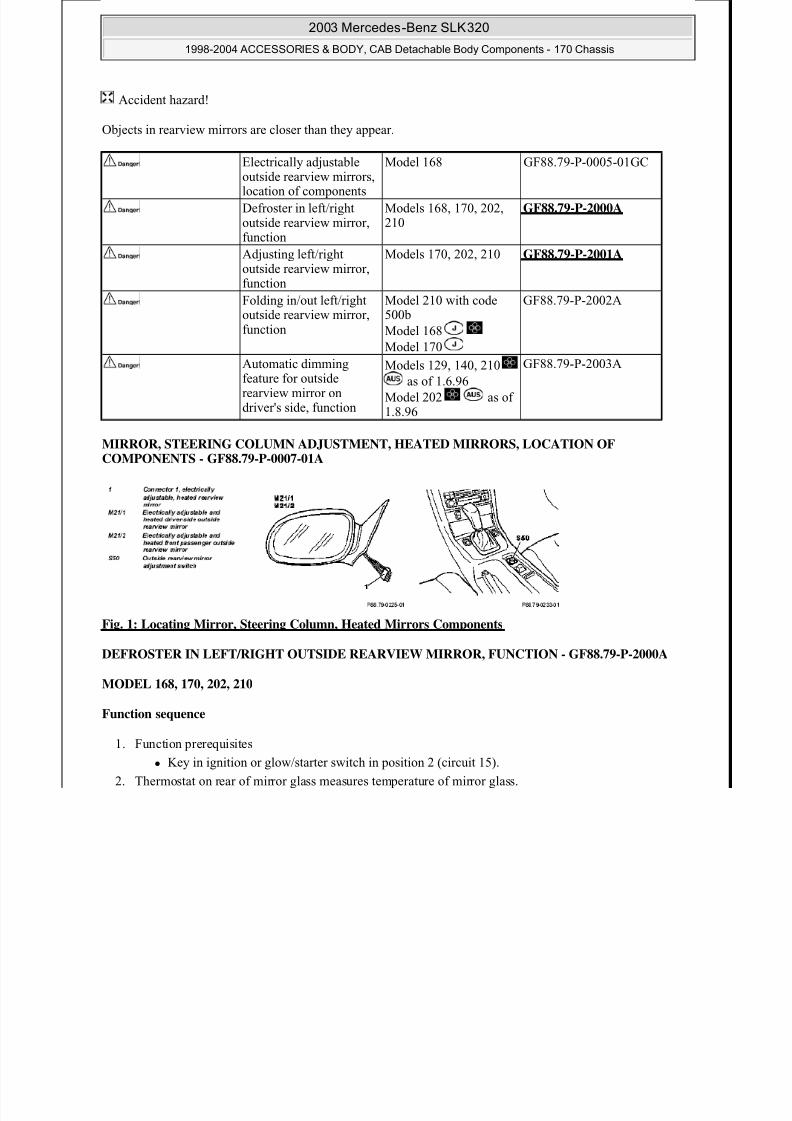
MIRROR, STEERING COLUMN ADJUSTMENT, HEATED MIRRORS, LOCATION OFCOMPONENTS - GF88.79-P-0007-01A
Fig. 1: Locating Mirror, Steering Column, Heated Mirrors Components
DEFROSTER IN LEFT/RIGHT OUTSIDE REARVIEW MIRROR, FUNCTION - GF88.79-P-2000A
MODEL 168, 170, 202, 210
Function sequence
1. Function prerequisites
Key in ignition or glow/starter switch in position 2 (circuit 15).
2. Thermostat on rear of mirror glass measures temperature of mirror glass.
Electrically adjustableoutside rearview mirrors,location of components
Model 168 GF88.79-P-0005-01GC
Defroster in left/rightoutside rearview mirror,
function
Models 168, 170, 202,210
GF88.79-P-2000A
Adjusting left/rightoutside rearview mirror,function
Models 170, 202, 210 GF88.79-P-2001A
Folding in/out left/rightoutside rearview mirror,function
Model 210 with code500b
Model 168
Model 170
GF88.79-P-2002A
Automatic dimmingfeature for outsiderearview mirror ondriver's side, function
Models 129, 140, 210
as of 1.6.96
Model 202 as of1.8.96
GF88.79-P-2003A
2003 Mercedes-Benz SLK320
1998-2004 ACCESSORIES & BODY, CAB Detachable Body Components - 170 Chassis

8/11/2019 BODY COMPONENTS.pdf
http://slidepdf.com/reader/full/body-componentspdf 3/105
3. At a mirror glass temperature of < or = 15 °C the mirror defroster is switched on by the thermostat.
4. Upon reaching the temperature of > or = 25 °C on the mirror glass the mirror defroster is switched off bythe thermostat.
5. The mirror defroster continues to be switched on and off until the temperature on the mirror remains > or= 15 °C.
FUNCTION, ADJUSTING LEFT/RIGHT OUTSIDE REARVIEW MIRROR - GF88.79-P-2001A
MODEL 202, 210
MODEL 170 except CODE (498) Japanese version
Fig. 2: Identifying Outside Rearview Mirror Vertical, Horizontal And Left/Right Adjustment
Function sequence
1. Function prerequisites
Key in ignition lock in position 2 (C. 15).
2. Switch (S21s8) turned to mirror to be adjusted (left or right). Outside rearview mirror vertical adjustment
(S21s6)
Outside rearview mirror horizontal adjustment (S21s7)
3. The position of the mirror glass is adjusted by the motor in the outside rearview mirror.
Mirror defroster,location/purpose
Model 168 GF88.79-P-4103GC
Purpose and location ofcomponents
Left/right outside rearviewmirror, purpose/location
GF88.79-P-3000A
Outside rearview mirroradjustment switch, purpose/location
GF88.79-P-3001A
2003 Mercedes-Benz SLK320
1998-2004 ACCESSORIES & BODY, CAB Detachable Body Components - 170 Chassis
8/11/2019 BODY COMPONENTS.pdf
http://slidepdf.com/reader/full/body-componentspdf 4/105
LEFT/RIGHT OUTSIDE REARVIEW MIRROR, LOCATION/PURPOSE - GF88.79-P-3000A
MODEL 129, 140, 170, 202 up to 31.5.97, 210 / (except 210.081 /281) up to 28.2.97
OUTSIDE REARVIEW MIRROR ADJUSTMENT SWITCH, LOCATION/PURPOSE - GF88.79-P-
3001A
MODEL 210 / (except 210.081 /281) up to 28.2.97
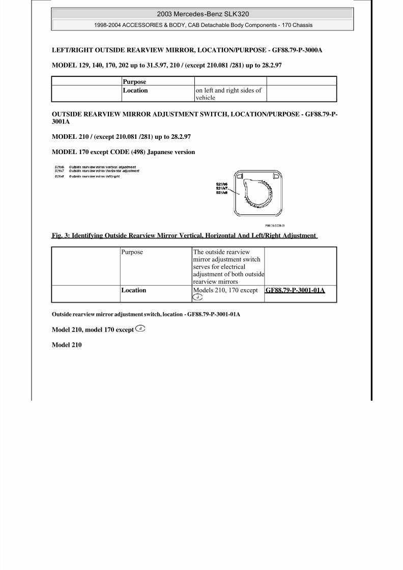
MODEL 170 except CODE (498) Japanese version
Fig. 3: Identifying Outside Rearview Mirror Vertical, Horizontal And Left/Right Adjustment
Outside rearview mirror adjustment switch, location - GF88.79-P-3001-01A
Model 210, model 170 except
Model 210
Purpose
Location on left and right sides ofvehicle
Purpose The outside rearviewmirror adjustment switchserves for electricaladjustment of both outsiderearview mirrors
Location Models 210, 170 except GF88.79-P-3001-01A
2003 Mercedes-Benz SLK320
1998-2004 ACCESSORIES & BODY, CAB Detachable Body Components - 170 Chassis

8/11/2019 BODY COMPONENTS.pdf
http://slidepdf.com/reader/full/body-componentspdf 5/105
Fig. 4: Identifying Outside Rearview Mirror Vertical, Horizontal, Left/Right Adjustment And MirrorSwitch - Model 210
Model 170 except
Fig. 5: Identifying Outside Rearview Mirror Vertical, Horizontal And Left/Right Adjustment - Model170 Except Japan
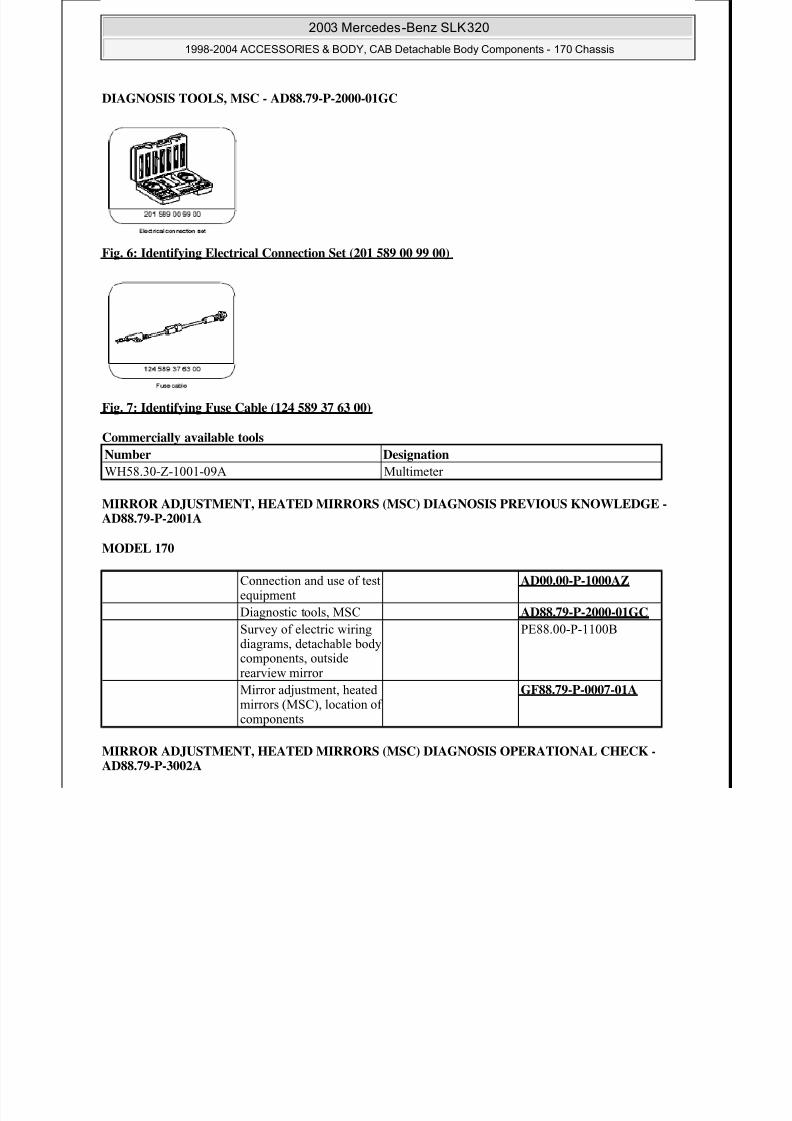
SELF-DIAGNOSTIC SYSTEM
MIRROR ADJUSTMENT, HEATED MIRRORS (MSC) DIAGNOSIS CONTENTS - AD88.79-P-1001AZ
MODEL 170
A 12.5 [] 11 Mirror adjustment, heatedmirrors (MSC) diagnosis, basic knowledge
D88.79-P-2001A
A 12.5 [] 12 Mirror adjustment, heatedmirrors (MSC) diagnosis,function check
AD88.79-P-3002A
A 12.5 [] 13 Mirror adjustment, heatedmirrors (MSC) diagnosis,
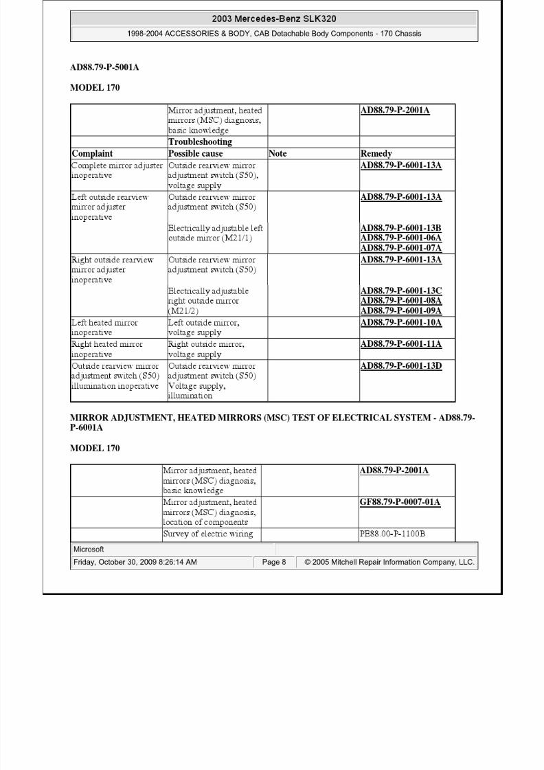
troubleshooting
AD88.79-P-5001A
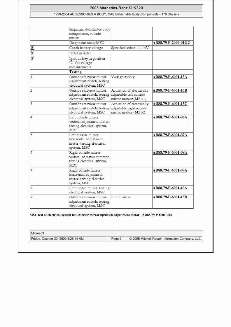
A 12.5 [] 21 Mirror adjustment, heatedmirrors (MSC), testingelectrical system
AD88.79-P-6001A
2003 Mercedes-Benz SLK320
1998-2004 ACCESSORIES & BODY, CAB Detachable Body Components - 170 Chassis
8/11/2019 BODY COMPONENTS.pdf
http://slidepdf.com/reader/full/body-componentspdf 6/105
8/11/2019 BODY COMPONENTS.pdf
http://slidepdf.com/reader/full/body-componentspdf 7/105
MODEL 170
MIRROR ADJUSTMENT, HEATED MIRRORS (MSC) DIAGNOSIS TROUBLESHOOTING -
Mirror adjustment, heatedmirrors (MSC) diagnosis, basic knowledge
AD88.79-P-2001A
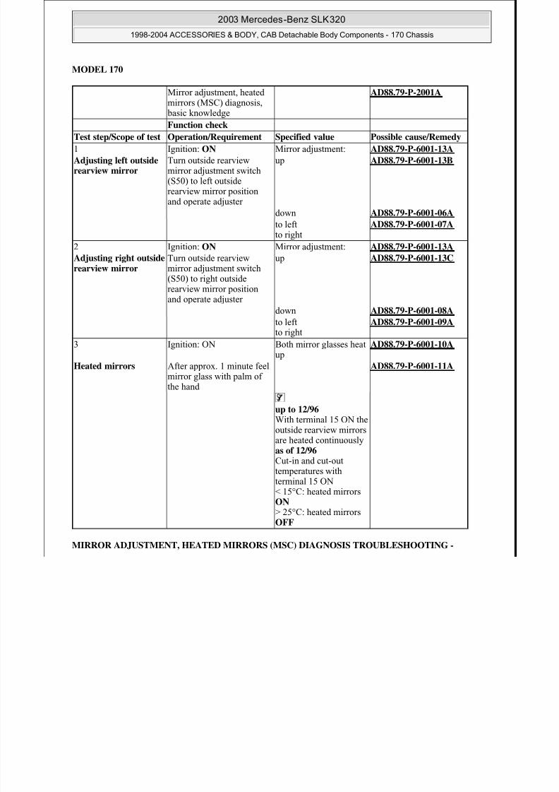
Function check
Test step/Scope of test Operation/Requirement Specified value Possible cause/Remedy
1 Ignition: ON Mirror adjustment: AD88.79-P-6001-13A
Adjusting left outsiderearview mirror
Turn outside rearviewmirror adjustment switch(S50) to left outsiderearview mirror positionand operate adjuster
up AD88.79-P-6001-13B
down AD88.79-P-6001-06A
to leftto right
AD88.79-P-6001-07A
2 Ignition: ON Mirror adjustment: AD88.79-P-6001-13AAdjusting right outsiderearview mirror
Turn outside rearviewmirror adjustment switch(S50) to right outsiderearview mirror positionand operate adjuster
up AD88.79-P-6001-13C
down AD88.79-P-6001-08A
to left
to right
AD88.79-P-6001-09A
3 Ignition: ON Both mirror glasses heatup
AD88.79-P-6001-10A
Heated mirrors After approx. 1 minute feelmirror glass with palm ofthe hand
AD88.79-P-6001-11A
up to 12/96
With terminal 15 ON theoutside rearview mirrorsare heated continuouslyas of 12/96 Cut-in and cut-outtemperatures withterminal 15 ON< 15°C: heated mirrors
ON > 25°C: heated mirrorsOFF
2003 Mercedes-Benz SLK320
1998-2004 ACCESSORIES & BODY, CAB Detachable Body Components - 170 Chassis
8/11/2019 BODY COMPONENTS.pdf
http://slidepdf.com/reader/full/body-componentspdf 8/105
8/11/2019 BODY COMPONENTS.pdf
http://slidepdf.com/reader/full/body-componentspdf 9/105

8/11/2019 BODY COMPONENTS.pdf
http://slidepdf.com/reader/full/body-componentspdf 10/105
Fig. 8: MSC Test Of Electrical System Left Exterior Mirror Up/Down Adjustment Motor
MSC test of electrical system left exterior mirror in/out adjustment motor - AD88.79-P-6001-07A
Fig. 9: MSC Test Of Electrical System Left Exterior Mirror In/Out Adjustment Motor
MSC test of electrical system right exterior mirror up/down adjustment motor - AD88.79-P-6001-08A
Fig. 10: MSC Test Of Electrical System Right Exterior Mirror Up/Down Adjustment Motor
MSC test of electrical system right exterior mirror in/out adjustment motor - AD88.79-P-6001-09A
2003 Mercedes-Benz SLK320
1998-2004 ACCESSORIES & BODY, CAB Detachable Body Components - 170 Chassis
8/11/2019 BODY COMPONENTS.pdf
http://slidepdf.com/reader/full/body-componentspdf 11/105
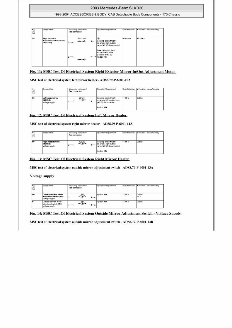
Fig. 11: MSC Test Of Electrical System Right Exterior Mirror In/Out Adjustment Motor
MSC test of electrical system left mirror heater - AD88.79-P-6001-10A
Fig. 12: MSC Test Of Electrical System Left Mirror Heater
MSC test of electrical system right mirror heater - AD88.79-P-6001-11A
Fig. 13: MSC Test Of Electrical System Right Mirror Heater
MSC test of electrical system outside mirror adjustment switch - AD88.79-P-6001-13A
Voltage supply
Fig. 14: MSC Test Of Electrical System Outside Mirror Adjustment Switch - Voltage Supply
MSC test of electrical system outside mirror adjustment switch - AD88.79-P-6001-13B
2003 Mercedes-Benz SLK320
1998-2004 ACCESSORIES & BODY, CAB Detachable Body Components - 170 Chassis

8/11/2019 BODY COMPONENTS.pdf
http://slidepdf.com/reader/full/body-componentspdf 12/105
Actuation of electrically adjustable left outside mirror motors (M21/1)
Fig. 15: MSC Test Of Electrical System Outside Mirror Adjustment Switch - Actuation Of Electrically
Adjustable Left Outside Mirror Motors
MSC test of electrical system outside mirror adjustment switch - AD88.79-P-6001-13C
Actuation of electrically adjustable right outside mirror motors (M21/2)
Fig. 16: MSC Test Of Electrical System Outside Mirror Adjustment Switch - Actuation Of ElectricallyAdjustable Right Outside Mirror Motors
MSC test of electrical system outside mirror adjustment switch - AD88.79-P-6001-13D
Illumination
2003 Mercedes-Benz SLK320
1998-2004 ACCESSORIES & BODY, CAB Detachable Body Components - 170 Chassis

8/11/2019 BODY COMPONENTS.pdf
http://slidepdf.com/reader/full/body-componentspdf 13/105
Fig. 17: MSC Test Of Electrical System Outside Mirror Adjustment Switch - Illumination
TESTING & REPAIR
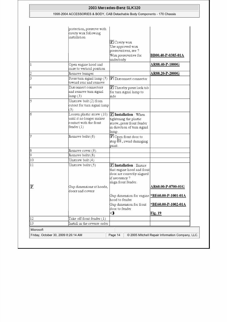
REMOVE/INSTALL FRONT FENDERS - AR88.10-P-1000G
MODEL 170
Fig. 18: Identifying Front Fenders Remove/Install Components
Modification notes
30.4.98 Remove fender liner andwheelhouse covereliminated
Previously step 3
30.4.98 Remove paneling fromouter A-pillar eliminated
Previously step 5
Remove/install
When replacing frontfender apply MB permanent underbody
2003 Mercedes-Benz SLK320
1998-2004 ACCESSORIES & BODY, CAB Detachable Body Components - 170 Chassis
8/11/2019 BODY COMPONENTS.pdf
http://slidepdf.com/reader/full/body-componentspdf 14/105
2003 Mercedes Benz SLK320

8/11/2019 BODY COMPONENTS.pdf
http://slidepdf.com/reader/full/body-componentspdf 15/105
Test and adjustment values, gap dimensions at hoods, doors and covers
Fig. 19: Identifying Feeler Gage (129 589 03 21 00)
REMOVING AND INSTALLING INNER FENDER IN FRONT FENDER - AR88.10-P-1300G
MODEL 170
Number Designation Model 170BE60.00-P-1001-01A
Gap dimension Engine hood tofender
Dimension "A" mm 4.0 (± 0.5)
Engine hood toheadlamp
Dimension "R" mm6.0 (+1/-0.5)
Engine hood toradiator grille
Dimension "O" mm7.0 (+1/-0.5)
Radiator grill to
headlamp
Dimension "N" mm5.0 (+1/-0.5)
Fig., see AR60.00-P-0700-01G
BE60.00-P-1002-01A
Gap dimension Front door to A- pillar
Dimension "B" mm-
Front door tofender
Dimension "H" mm4.0 (± 0.5)
Front door to
rear door
Dimension "I" mm-
Front door toroof
Dimension "C" mm-
Rear door toupper sidesection
Dimension "D" mm-
Rear door tolower side
section
Dimension "J" mm-
Fender to A- pillar
Dimension "Q" mm4.0 (± 1.6)
Front door torear fender
Dimension "P" mm4.0 (± 0.5)
Fig., see AR60.00-P-0700-01G
2003 Mercedes-Benz SLK320
1998-2004 ACCESSORIES & BODY, CAB Detachable Body Components - 170 Chassis
2003 Mercedes Benz SLK320

8/11/2019 BODY COMPONENTS.pdf
http://slidepdf.com/reader/full/body-componentspdf 16/105
Fig. 20: Identifying Inner Fender In Front Fender Remove/Install Components
Revisions
REMOVING AND INSTALLING FRONT BUMPER - AR88.20-P-2000
Removing and installing front bumper - AR88.20-P-2000G
MODEL 170 up to 31.Jan.00
30.4.98 Removing wheelhousedeleted
Previously step 1 AR88.10-P-1300G
Removal, installation
1 Remove wheel
2 Remove sound-proofingcapsule below engine
3 Remove inner fender (1) Installation : Clipinner fender (1) into coverfor wheelhouse innerfender (2) (arrow)
4 Remove cover forwheelhouse inner fender(2)
On vehicles withcharge air cooler, presscharge air tube to side, ifnecessary
2003 Mercedes-Benz SLK320
1998-2004 ACCESSORIES & BODY, CAB Detachable Body Components - 170 Chassis
2003 Mercedes-Benz SLK320

8/11/2019 BODY COMPONENTS.pdf
http://slidepdf.com/reader/full/body-componentspdf 17/105
Fig. 21: Identifying Front Bumper Remove/Install Components - Model 170 Up To 31.Jan.00
Modification notes
30.4.98 Removal of road wheelsis no longer required
Previously step 2
30.4.98 Removal of wheel arch
panel is no longerrequired
Previously step 5
30.4.98 Clip has been replaced byscrew (11) with collar nut(12)
Step 6
Removing, installing
1 Open engine hood AR88.40-P-1000G2 Separate the connectors
on the right and left turnindicator lamps (7)
3 Remove the right and leftturn indicator lamps (7)
Disengage turnindicator lock tabs by pushing them to the side
4 Separate right and left foglamp connectors (9) The connectors can bereached through anopening in the wheel arch panel of the front fender.
5 Separate the connector(10) for the outside
Cf. code (240a)outside temperature
2003 Mercedes Benz SLK320
1998-2004 ACCESSORIES & BODY, CAB Detachable Body Components - 170 Chassis

8/11/2019 BODY COMPONENTS.pdf
http://slidepdf.com/reader/full/body-componentspdf 18/105
2003 Mercedes-Benz SLK320
8/11/2019 BODY COMPONENTS.pdf
http://slidepdf.com/reader/full/body-componentspdf 19/105
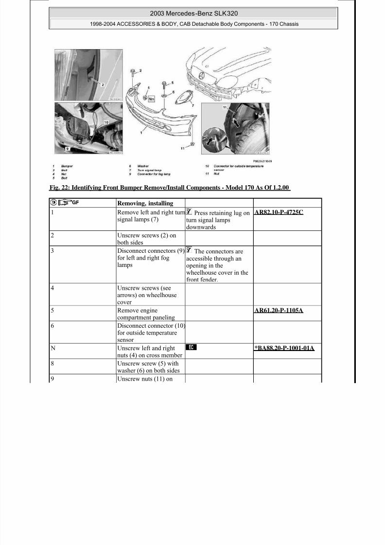
Fig. 22: Identifying Front Bumper Remove/Install Components - Model 170 As Of 1.2.00
Removing, installing
1 Remove left and right turnsignal lamps (7)
Press retaining lug onturn signal lampsdownwards
AR82.10-P-4725C
2 Unscrew screws (2) on both sides
3 Disconnect connectors (9)for left and right foglamps
The connectors areaccessible through anopening in thewheelhouse cover in thefront fender.
4 Unscrew screws (seearrows) on wheelhousecover
5 Remove enginecompartment paneling
AR61.20-P-1105A
6 Disconnect connector (10)for outside temperaturesensor
N Unscrew left and rightnuts (4) on cross member
*BA88.20-P-1001-01A
8 Unscrew screw (5) withwasher (6) on both sides
9 Unscrew nuts (11) on
1998-2004 ACCESSORIES & BODY, CAB Detachable Body Components - 170 Chassis
2003 Mercedes-Benz SLK320

8/11/2019 BODY COMPONENTS.pdf
http://slidepdf.com/reader/full/body-componentspdf 20/105
BUMPER
REMOVE/INSTALL REAR BUMPER - AR88.20-P-2200G
MODEL 170
Fig. 23: Identifying Rear Bumper Remove/Install Components (1 Of 2)
both sides
10 Remove bumper (1) To remove pull bumper forward slightlyto avoid damaging paint.
Bumper is clipped inarea of radiator grille.
11 Install in the reverse order
Number Designation Model 170
BA88.20-P-1001-01A Nuts for front bumper oncross member
Nm 10 ± 2
1998-2004 ACCESSORIES & BODY, CAB Detachable Body Components - 170 Chassis
2003 Mercedes-Benz SLK320

8/11/2019 BODY COMPONENTS.pdf
http://slidepdf.com/reader/full/body-componentspdf 21/105
Fig. 24: Identifying Rear Bumper Remove/Install Components (2 Of 2)
Removal/installation
1 Remove paneling from rearcenter section
AR68.30-P-4785G
2 Remove left and right side paneling
AR68.30-P-4800G
3 Open trunk lid Turn lid in normal position
4 Fasten connector (10) fortrunk luggage cover"closed limit switch(S69/10) with tie strap
Do not damagecontact (10) of trunkluggage cover "closed"limit switch (S69/10) toensure proper function
Do not disconnect
connector.
5 Disconnect antenna lines(9) from left rear bumperantenna amplifier (A2/26)and press grommet towardoutside
Do not damageantenna lines (9) toensure for properfunction
Installation :Grommet for antenna
lines (9) should be seatedsecurely in fender to prevent water ingress
6 Unscrew nut (7) andremove toothed lockwasher (8)
*BA88.20-P-1002-01A
7 Unscrew bolts (3) frominner fender, remove
washers (4) and sealingwashers (5)
Installation : Checksealing washers (5),
replace if necessary
8 Unscrew nut (2) from bolt(1) on outer left and right
9 Remove bumper (6) Remove bumper
1998-2004 ACCESSORIES & BODY, CAB Detachable Body Components - 170 Chassis
2003 Mercedes-Benz SLK320

8/11/2019 BODY COMPONENTS.pdf
http://slidepdf.com/reader/full/body-componentspdf 22/105
BUMPER
OPENING ENGINE HOOD, MOVING TO UPRIGHT POSITION, CLOSING - AR88.40-P-1000G
MODEL 170
Fig. 25: Identifying Engine Hood Opening/Closing Components
toward rear.
10.1 Modify the AMG-bumper Installation : Seeinstallation instructionsfor accessories
Retrofitting AMG trims AZ88.00-P-0001I
11 Install in the reverse order
Number Designation Model 170
BA88.20-P-1002-01A Nut for rear bumper onrear center section
Nm 10
Contact with componentsunder high voltage can pose lethal hazard
Do not touch parts underhigh voltage. People withelectronic implants (e.g.heart pacemakers) shouldnot perform work onignition system.
AS15.10-Z-0001-01A
Opening
1 Pull lever on left belowinstrument panel (1) to
Engine hood shouldspring open, if necessary
1998-2004 ACCESSORIES & BODY, CAB Detachable Body Components - 170 Chassis
2003 Mercedes-Benz SLK320
8/11/2019 BODY COMPONENTS.pdf
http://slidepdf.com/reader/full/body-componentspdf 23/105
REMOVING AND INSTALLING ENGINE HOOD - AR88.40-P-3000G
MODEL 170
release engine hood (2) lift engine hood slightly
2 Press levers for safetyhooks (arrow) against stopon engine hood (2) andopen engine hood untilthe locking knob (4)catches
Windshield wiper armmust not be foldedforward
The locking knobsymbol "PRESS" should be completely visible inthe opening in the gas pressure strut cover tube
Moving to uprightposition
3 Press locking knobsymbol "PRESS" inopening in gas pressurestrut cover tube and moveengine hood (2) to upright position until locking
knob (5) catches
The locking knobsymbol "PRESS" must becompletely visible in theopening in the gas pressure strut cover tube
Closing
4 Press locking knobsymbol "PRESS" in theopening in the gas pressure strut cover tubeand pull engine hood (2)down against the pressure
of the gas pressure strut(3)
The locking knobsymbol "PRESS" must becompletely visible in theopening in the gas pressure strut cover tube
5 Close engine hood (2) Position hands on frontedge of engine hood only
6 Check locking function ofengine hood lock
1998-2004 ACCESSORIES & BODY, CAB Detachable Body Components - 170 Chassis
2003 Mercedes-Benz SLK320

8/11/2019 BODY COMPONENTS.pdf
http://slidepdf.com/reader/full/body-componentspdf 24/105
Fig. 26: Identifying Engine Hood Remove/Install Components
Removal, installation
Sealing joints followingrepairs
Includes sealing jointson engine hood
AR97.10-P-4000G
Hollow cavity preservation following
repair
Includes hollow cavity preservation on engine
hood
AR97.20-P-1500G
1 Open engine hood (1) andmove to upright position
AR88.40-P-1000G
2 Unscrew bottom four bolts (4) in engine hood(1)
*BA88.40-P-1001-01A
The engine hood is
held in place by the safetyhooks on the engine hoodhinges (5)
Installation : Move bolts to coincide with pressure points in paintEnsure that engine hoodfits correctly, if
necessary ?
Adjust engine hood AR88.40-P-3020G
3 Unclip retainer (2) andunhook gas pressure strut(3) from engine hood (1)
1998-2004 ACCESSORIES & BODY, CAB Detachable Body Components - 170 Chassis
2003 Mercedes-Benz SLK320
1998 2004 ACCESSORIES & BODY CAB D t h bl B d C t 170 Ch i
8/11/2019 BODY COMPONENTS.pdf
http://slidepdf.com/reader/full/body-componentspdf 25/105
ENGINE HOOD
ADJUST ENGINE HOOD - AR88.40-P-3020G
MODEL 170
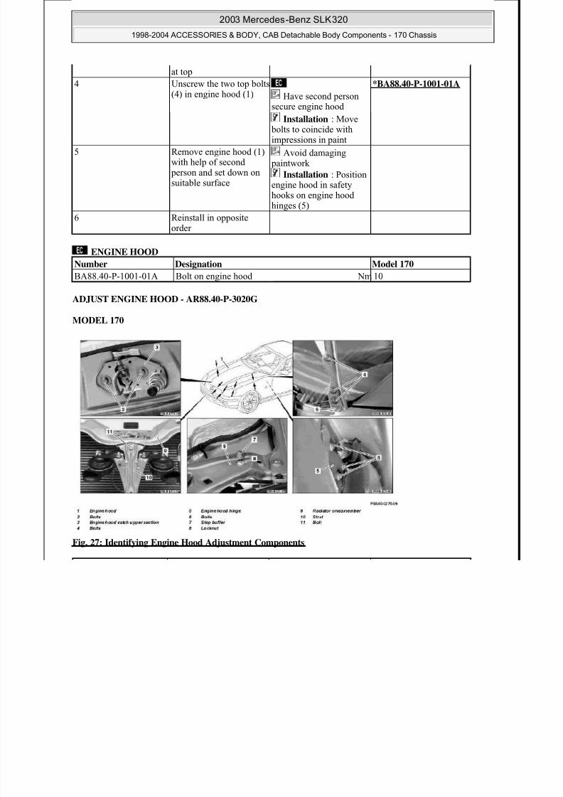
Fig. 27: Identifying Engine Hood Adjustment Components
at top
4 Unscrew the two top bolts(4) in engine hood (1) Have second person
secure engine hood
*BA88.40-P-1001-01A
Installation : Move bolts to coincide withimpressions in paint
5 Remove engine hood (1)with help of second
person and set down onsuitable surface
Avoid damaging paintwork
Installation : Positionengine hood in safetyhooks on engine hoodhinges (5)
6 Reinstall in oppositeorder
Number Designation Model 170
BA88.40-P-1001-01A Bolt on engine hood Nm 10
1998-2004 ACCESSORIES & BODY, CAB Detachable Body Components - 170 Chassis

8/11/2019 BODY COMPONENTS.pdf
http://slidepdf.com/reader/full/body-componentspdf 26/105

8/11/2019 BODY COMPONENTS.pdf
http://slidepdf.com/reader/full/body-componentspdf 27/105
2003 Mercedes-Benz SLK320
1998-2004 ACCESSORIES & BODY CAB Detachable Body Components - 170 Chassis

8/11/2019 BODY COMPONENTS.pdf
http://slidepdf.com/reader/full/body-componentspdf 28/105
Fig. 28: Identifying Feeler Gage (129 589 03 21 00)
REMOVING AND INSTALLING ENGINE HOOD HINGE - AR88.40-P-3060G
MODEL 170
Fig. 29: Identifying Engine Hood Hinge Remove/Install Components
Removal, installation
1 Remove engine hood AR88.40-P-3000G
2 Remove inner fender infront fender
AR88.10-P-1300G
3 Mark installation positionof engine hood hinge (1)
This facilitatesinstallation
4 Unscrew bolts (2) and
remove engine hoodhinge (1)
Installation : Observemarking on wheelhouse panel
*BA88.40-P-1005-01A
Preserve engine hoodhinges with hollow cavity
1998 2004 ACCESSORIES & BODY, CAB Detachable Body Components 170 Chassis
2003 Mercedes-Benz SLK320
1998-2004 ACCESSORIES & BODY, CAB Detachable Body Components - 170 Chassis

8/11/2019 BODY COMPONENTS.pdf
http://slidepdf.com/reader/full/body-componentspdf 29/105
ENGINE HOOD
REMOVING AND INSTALLING PULL CABLE FOR ENGINE HOOD - AR88.40-P-3100G
MODEL 170
Fig. 30: Identifying Pull Cable For Engine Hood Remove/Install Components
wax.Use approved wax preservation agent, seeService Microfiche,Specifications for service products, sheet no. 385
5 Reinstall in oppositeorder
Number Designation Model 170
BA88.40-P-1005-01A Bolt on engine hoodhinge
Nm 10
Removal, installation
1 Open engine hood andmove to upright position
AR88.40-P-1000G
2 Unscrew screw (8) onhandle (7)
3 Pull handle (7) out ofarresting mechanism incover and unhook engine
, y p
8/11/2019 BODY COMPONENTS.pdf
http://slidepdf.com/reader/full/body-componentspdf 30/105
2003 Mercedes-Benz SLK320
1998-2004 ACCESSORIES & BODY, CAB Detachable Body Components - 170 Chassis
8/11/2019 BODY COMPONENTS.pdf
http://slidepdf.com/reader/full/body-componentspdf 31/105
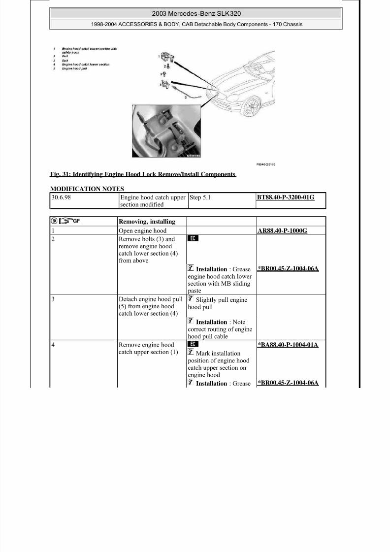
Fig. 31: Identifying Engine Hood Lock Remove/Install Components
MODIFICATION NOTES
30.6.98 Engine hood catch uppersection modified
Step 5.1 BT88.40-P-3200-01G
Removing, installing
1 Open engine hood AR88.40-P-1000G
2 Remove bolts (3) andremove engine hoodcatch lower section (4)from above
Installation : Greaseengine hood catch lowersection with MB sliding
paste
*BR00.45-Z-1004-06A
3 Detach engine hood pull(5) from engine hoodcatch lower section (4)
Slightly pull enginehood pull
Installation : Notecorrect routing of enginehood pull cable
4 Remove engine hood
catch upper section (1)
Mark installation position of engine hoodcatch upper section onengine hood
*BA88.40-P-1004-01A
Installation : Grease *BR00.45-Z-1004-06A
8/11/2019 BODY COMPONENTS.pdf
http://slidepdf.com/reader/full/body-componentspdf 32/105
2003 Mercedes-Benz SLK320
1998-2004 ACCESSORIES & BODY, CAB Detachable Body Components - 170 Chassis

8/11/2019 BODY COMPONENTS.pdf
http://slidepdf.com/reader/full/body-componentspdf 33/105
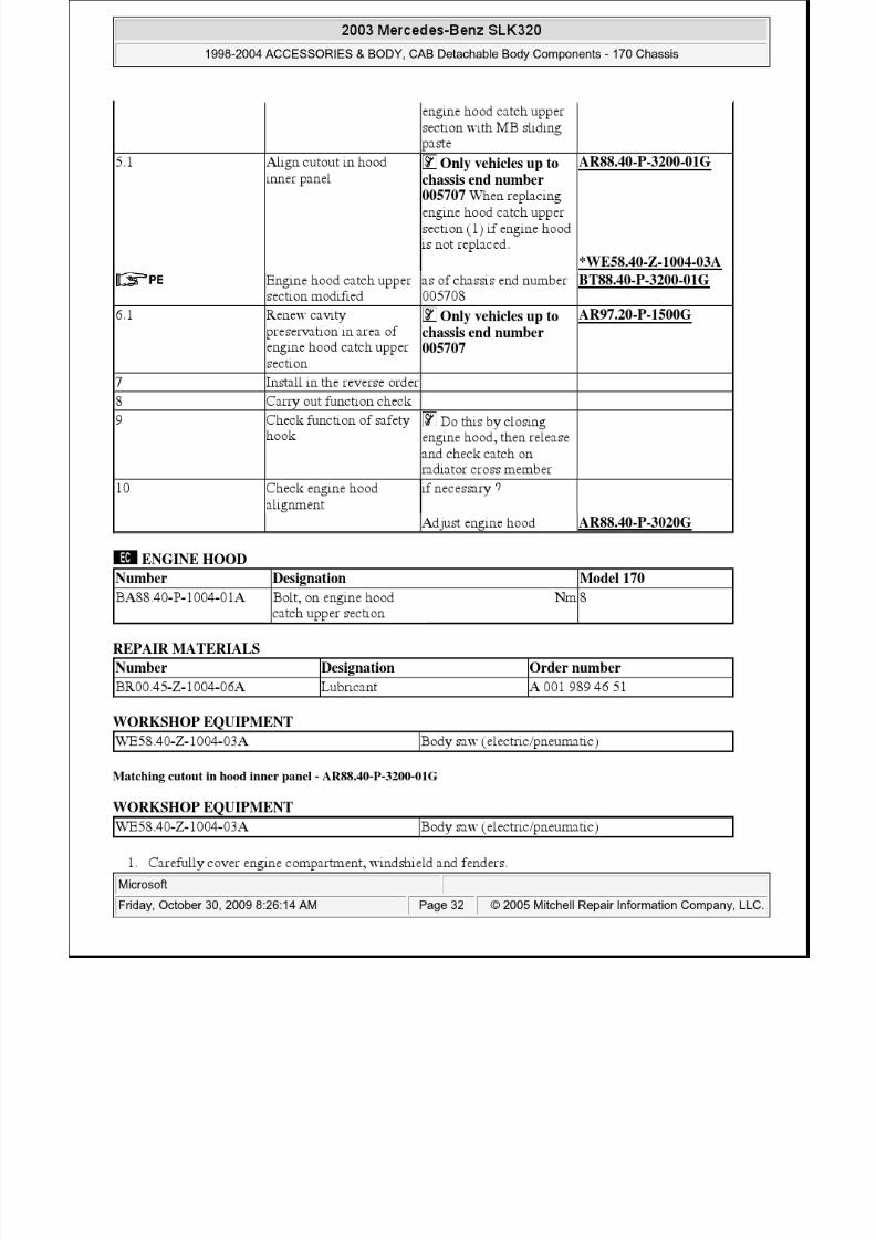
Thoroughly remove chippings from cavities produced during repairs.
2. Mark cutout according to drawing.
Fig. 32: Identifying Hood Inner Panel Cutout Dimensions
3. Saw out cutout (arrow)
4. Deburr cut edges using a file
5. Carry out corrosion prevention measures
Fig. 33: Identifying Cutout Sawing Area
6. Mount engine hood catch upper section (1) in rearmost position
Actuating lever (2) must not touch front fold of engine hood. If necessary leave out rubber beading (3)in this area.
7. Check function and adjustment
2003 Mercedes-Benz SLK320
1998-2004 ACCESSORIES & BODY, CAB Detachable Body Components - 170 Chassis

8/11/2019 BODY COMPONENTS.pdf
http://slidepdf.com/reader/full/body-componentspdf 34/105
Fig. 34: Identifying Engine Hood Catch Upper Section, Actuating Lever & Rubber Beading
REMOVING AND INSTALLING TRUNK LID - AR88.50-P-5000G
MODEL 170
Fig. 35: Identifying Trunk Lid Remove/Install Components
Removal, installation
Sealing joints followingrepair
Includes sealing jointson trunk lid
AR97.10-P-4000G
Preserving hollowcavities following repair
Includes preservinghollow cavities in trunk
lid
AR97.20-P-1500G
1 Remove trunk lid andstriker eye
Do not separate strikereye
AR88.50-P-5020G
2 Disconnect connectors (4)
3 Open or separate holder
2003 Mercedes-Benz SLK320
1998-2004 ACCESSORIES & BODY, CAB Detachable Body Components - 170 Chassis

8/11/2019 BODY COMPONENTS.pdf
http://slidepdf.com/reader/full/body-componentspdf 35/105
TRUNK LID
REMOVING, INSTALLING AND ADJUSTING TRUNK LID LOCK AND STRIKER EYE - AR88.50-P-5020
Removing, installing and adjusting trunk lid lock and striker eye - AR88.50-P-5020G
MODEL 170 up to 31.1.00
(3) for electric wiringharness and pull wiring
harness out of trunk lid 4 Mark position of hinge
lever on trunk lid (1),loosen bolts (2) andunscrew two bolts oneach side
*BA88.50-P-1009-01A
5 Unhook gas pressure strut(5) from trunk lid with aidof second mechanic,unscrew bolts (2) andremove trunk lid (1)
6 Reinstall in oppositeorder
Check adjustment oftrunk lid, if necessary ?
Adjust trunk lid AR88.50-P-5200G
Number Designation Model 170
BA88.50-P-1009-01A Bolts for hinge lever ontrunk lid
Nm 25
2003 Mercedes-Benz SLK320
1998-2004 ACCESSORIES & BODY, CAB Detachable Body Components - 170 Chassis
8/11/2019 BODY COMPONENTS.pdf
http://slidepdf.com/reader/full/body-componentspdf 36/105
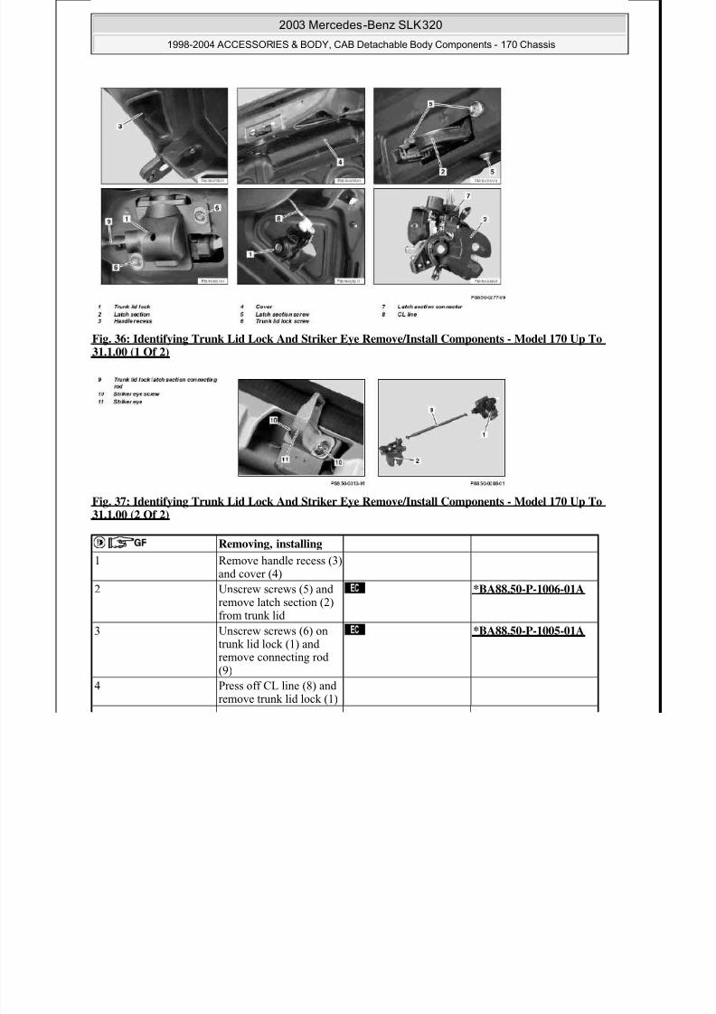
Fig. 36: Identifying Trunk Lid Lock And Striker Eye Remove/Install Components - Model 170 Up To31.1.00 (1 Of 2)
Fig. 37: Identifying Trunk Lid Lock And Striker Eye Remove/Install Components - Model 170 Up To31.1.00 (2 Of 2)
Removing, installing
1 Remove handle recess (3)and cover (4)
2 Unscrew screws (5) andremove latch section (2)from trunk lid
*BA88.50-P-1006-01A
3 Unscrew screws (6) on
trunk lid lock (1) andremove connecting rod(9)
*BA88.50-P-1005-01A
4 Press off CL line (8) andremove trunk lid lock (1)
2003 Mercedes-Benz SLK320
1998-2004 ACCESSORIES & BODY, CAB Detachable Body Components - 170 Chassis
8/11/2019 BODY COMPONENTS.pdf
http://slidepdf.com/reader/full/body-componentspdf 37/105
TRUNK LID
Removing, installing and adjusting trunk lid lock and striker eye - AR88.50-P-5020GA
MODEL 170 as of 1.2.00
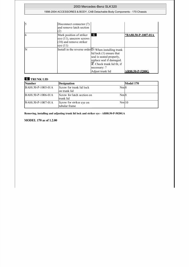
5 Disconnect connector (7)and remove latch section
(2)
6 Mark position of strikereye (11), unscrew screws(10) and remove strikereye (11)
*BA88.50-P-1007-01A
N Install in the reverse order When installing trunklid lock (1) ensure thatseal is seated properly,replace seal if damaged.
Check trunk lid fit, ifnecessary: ?
Adjust trunk lid AR88.50-P-5200G
Number Designation Model 170
BA88.50-P-1005-01A Screw for trunk lid lockon trunk lid
Nm 8
BA88.50-P-1006-01A Screw for latch section ontrunk lid
Nm 8
BA88.50-P-1007-01A Screw for striker eye ontubular frame
Nm 10
2003 Mercedes-Benz SLK320
1998-2004 ACCESSORIES & BODY, CAB Detachable Body Components - 170 Chassis
8/11/2019 BODY COMPONENTS.pdf
http://slidepdf.com/reader/full/body-componentspdf 38/105
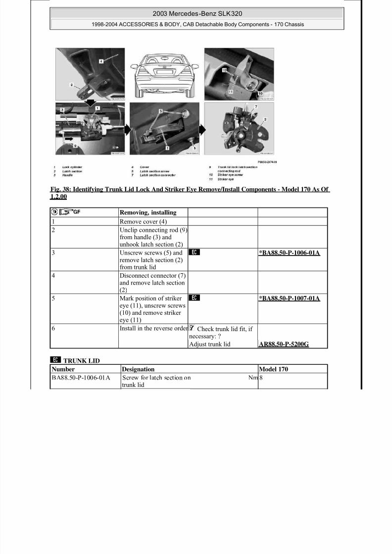
Fig. 38: Identifying Trunk Lid Lock And Striker Eye Remove/Install Components - Model 170 As Of1.2.00
TRUNK LID
Removing, installing
1 Remove cover (4)
2 Unclip connecting rod (9)
from handle (3) andunhook latch section (2)
3 Unscrew screws (5) andremove latch section (2)from trunk lid
*BA88.50-P-1006-01A
4 Disconnect connector (7)and remove latch section(2)
5 Mark position of strikereye (11), unscrew screws(10) and remove strikereye (11)
*BA88.50-P-1007-01A
6 Install in the reverse order Check trunk lid fit, ifnecessary: ?
Adjust trunk lid AR88.50-P-5200G
Number Designation Model 170
BA88.50-P-1006-01A Screw for latch section ontrunk lid
Nm 8
2003 Mercedes-Benz SLK320
1998-2004 ACCESSORIES & BODY, CAB Detachable Body Components - 170 Chassis

8/11/2019 BODY COMPONENTS.pdf
http://slidepdf.com/reader/full/body-componentspdf 39/105
REMOVING, INSTALLING TRUNK LID HANDLE WITH LOCK CYLINDER - AR88.50-P-5060G
MODEL 170 as of 1.2.00
Fig. 39: Identifying Trunk Lid Handle With Lock Cylinder Remove/Install Components - Model 170 AsOf 1.2.00 (1 Of 2)
Fig. 40: Identifying Trunk Lid Handle With Lock Cylinder Remove/Install Components - Model 170 AsOf 1.2.00 (2 Of 2)
BA88.50-P-1007-01A Screw for striker eye ontubular frame
Nm 10
Removing, installing
1 Remove cover behindtrunk lid handle (1)
2 Unscrew screws (21) andnut (22)
Nut (22) is located onthe rear of the left license
2003 Mercedes-Benz SLK320
1998-2004 ACCESSORIES & BODY, CAB Detachable Body Components - 170 Chassis

8/11/2019 BODY COMPONENTS.pdf
http://slidepdf.com/reader/full/body-componentspdf 40/105
REMOVE/INSTALL TUBULAR FRAME FOR TRUNK LID - AR88.50-P-5100G
MODEL 170
plate lamp (E19/1).
Installation : Replace
sealant on nut (22).3 Remove cover (2) and
disconnect connectionleads for left and rightlicense plate lamps(E19/1, E19/2)
4 Unclip connecting rod(11)
5 Pry pneumatic line (31)off with 7 mm open-endwrench
6 Unscrew nut (12) Installation : Replacesealant on nut (12).
N Unscrew screws (13) with plastic washers
Secure trunk lid handle(1) from falling out with
one hand.
8 Unclip lock cylinder (3)from trunk lid handle (1)(see arrows)
9 Install in the reverse order
2003 Mercedes-Benz SLK320
1998-2004 ACCESSORIES & BODY, CAB Detachable Body Components - 170 Chassis

8/11/2019 BODY COMPONENTS.pdf
http://slidepdf.com/reader/full/body-componentspdf 41/105
Fig. 41: Identifying Tubular Frame For Trunk Lid Remove/Install Components (1 Of 3)
Fig. 42: Identifying Tubular Frame For Trunk Lid Remove/Install Components (2 Of 3)
Fig. 43: Identifying Tubular Frame For Trunk Lid Remove/Install Components (3 Of 3)
Remove/Install
1 Remove side paneling intrunk
AR68.30-P-4800G
2 Remove cover plate (2)from rear center section
*BA77.33-P-1006-01A

8/11/2019 BODY COMPONENTS.pdf
http://slidepdf.com/reader/full/body-componentspdf 42/105

8/11/2019 BODY COMPONENTS.pdf
http://slidepdf.com/reader/full/body-componentspdf 43/105
2003 Mercedes-Benz SLK320
1998-2004 ACCESSORIES & BODY, CAB Detachable Body Components - 170 Chassis

8/11/2019 BODY COMPONENTS.pdf
http://slidepdf.com/reader/full/body-componentspdf 44/105
Fig. 44: Identifying Striker & Catch Socket
2. If required, correct longitudinal adjustment on striker (8). Adjust lateral direction on console (1)
Remove side paneling in trunk to adjust console (1)
Fig. 45: Identifying Console & Catch Socket
3. Open emergency actuation valve (N) to relieve pressure from hydraulic system.
Fig. 46: Identifying Emergency Actuation Valve
4. Open trunk lid and lay square tube (2) on fender in area of locks
Square tube approx.. 1500 mm long
2003 Mercedes-Benz SLK320
1998-2004 ACCESSORIES & BODY, CAB Detachable Body Components - 170 Chassis

8/11/2019 BODY COMPONENTS.pdf
http://slidepdf.com/reader/full/body-componentspdf 45/105
Protect fender against damage with adhesive tape.
Fig. 47: Identifying Square Tube On Fender In Area Of Locks
5. Measure distance (A) between square tube (2) and tubular frame (1) in middle of surface on tubular frame(1).
6. Loosen bolts (3) for striker (4) from tubular frame (1)
7. Adjust tubular frame (1) in direction of arrow, check distance (A) n and tighten bolts (3).
Fig. 48: Identifying Square Tube, Tubular Frame, Bolts, Striker & Distance Measurement
8. Close emergency actuation valve (N) and build up pressure in hydraulic system by actuating Vario
roof9. Measure distance between square tube and tubular frame again.
If the distance measured is outside the permissible tolerance adjust hydraulic cylinder
2003 Mercedes-Benz SLK320
1998-2004 ACCESSORIES & BODY, CAB Detachable Body Components - 170 Chassis
8/11/2019 BODY COMPONENTS.pdf
http://slidepdf.com/reader/full/body-componentspdf 46/105
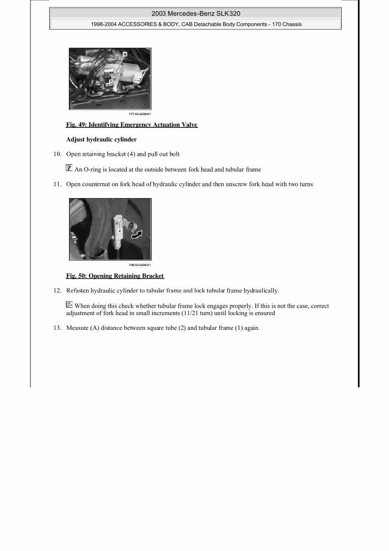
Fig. 49: Identifying Emergency Actuation Valve
Adjust hydraulic cylinder
10. Open retaining bracket (4) and pull out bolt
An O-ring is located at the outside between fork head and tubular frame
11. Open counternut on fork head of hydraulic cylinder and then unscrew fork head with two turns
Fig. 50: Opening Retaining Bracket
12. Refasten hydraulic cylinder to tubular frame and lock tubular frame hydraulically.
When doing this check whether tubular frame lock engages properly. If this is not the case, correctadjustment of fork head in small increments (11/21 turn) until locking is ensured
13. Measure (A) distance between square tube (2) and tubular frame (1) again.
2003 Mercedes-Benz SLK320
1998-2004 ACCESSORIES & BODY, CAB Detachable Body Components - 170 Chassis
8/11/2019 BODY COMPONENTS.pdf
http://slidepdf.com/reader/full/body-componentspdf 47/105
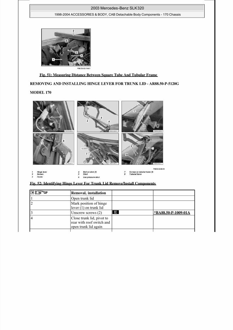
Fig. 51: Measuring Distance Between Square Tube And Tubular Frame
REMOVING AND INSTALLING HINGE LEVER FOR TRUNK LID - AR88.50-P-5120G
MODEL 170
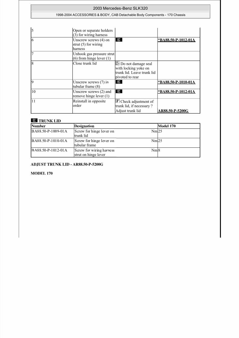
Fig. 52: Identifying Hinge Lever For Trunk Lid Remove/Install Components
Removal, installation
1 Open trunk lid
2 Mark position of hingelever (1) on trunk lid
3 Unscrew screws (2) *BA88.50-P-1009-01A
4 Close trunk lid, pivot torear with roof switch andopen trunk lid again
8/11/2019 BODY COMPONENTS.pdf
http://slidepdf.com/reader/full/body-componentspdf 48/105
2003 Mercedes-Benz SLK320
1998-2004 ACCESSORIES & BODY, CAB Detachable Body Components - 170 Chassis
8/11/2019 BODY COMPONENTS.pdf
http://slidepdf.com/reader/full/body-componentspdf 49/105
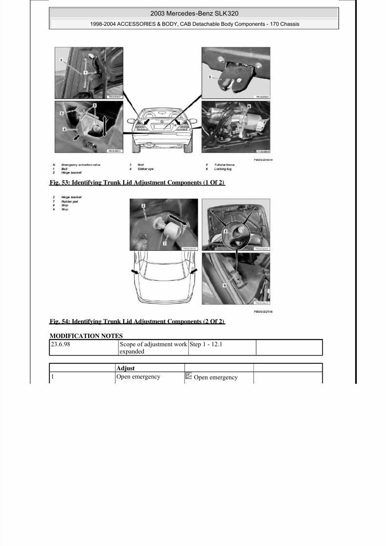
Fig. 53: Identifying Trunk Lid Adjustment Components (1 Of 2)
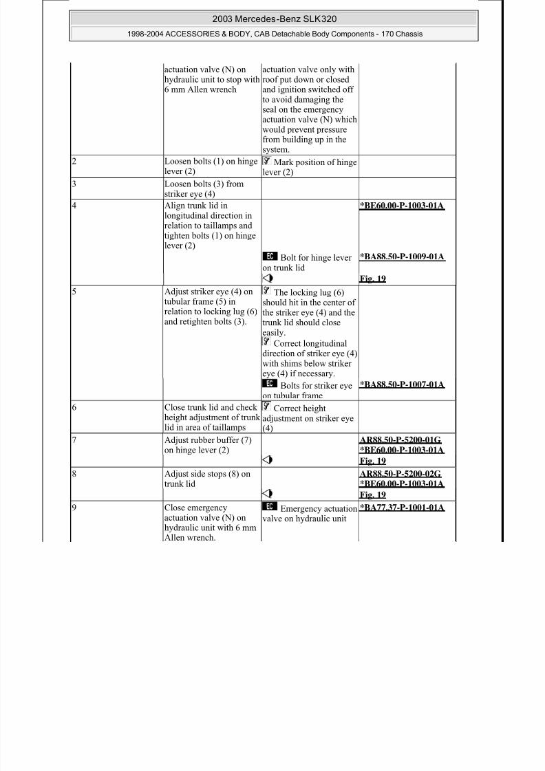
Fig. 54: Identifying Trunk Lid Adjustment Components (2 Of 2)
MODIFICATION NOTES
23.6.98 Scope of adjustment work
expanded
Step 1 - 12.1
Adjust
1 Open emergency Open emergency
2003 Mercedes-Benz SLK320
1998-2004 ACCESSORIES & BODY, CAB Detachable Body Components - 170 Chassis
8/11/2019 BODY COMPONENTS.pdf
http://slidepdf.com/reader/full/body-componentspdf 50/105
actuation valve (N) onhydraulic unit to stop with
6 mm Allen wrench
actuation valve only withroof put down or closed
and ignition switched offto avoid damaging theseal on the emergencyactuation valve (N) whichwould prevent pressurefrom building up in thesystem.
2 Loosen bolts (1) on hinge
lever (2)
Mark position of hinge
lever (2)
3 Loosen bolts (3) fromstriker eye (4)
4 Align trunk lid inlongitudinal direction inrelation to taillamps andtighten bolts (1) on hingelever (2)
*BE60.00-P-1003-01A
Bolt for hinge leveron trunk lid
*BA88.50-P-1009-01A
Fig. 19
5 Adjust striker eye (4) ontubular frame (5) inrelation to locking lug (6)and retighten bolts (3).
The locking lug (6)should hit in the center ofthe striker eye (4) and thetrunk lid should close
easily.Correct longitudinal
direction of striker eye (4)with shims below strikereye (4) if necessary.
Bolts for striker eyeon tubular frame
*BA88.50-P-1007-01A
6 Close trunk lid and check
height adjustment of trunklid in area of taillamps
Correct heightadjustment on striker eye(4)
7 Adjust rubber buffer (7)on hinge lever (2)
AR88.50-P-5200-01G *BE60.00-P-1003-01A
Fig. 19
8 Adjust side stops (8) ontrunk lid
AR88.50-P-5200-02G *BE60.00-P-1003-01A
Fig. 199 Close emergency
actuation valve (N) onhydraulic unit with 6 mmAllen wrench.
Emergency actuationvalve on hydraulic unit
*BA77.37-P-1001-01A

8/11/2019 BODY COMPONENTS.pdf
http://slidepdf.com/reader/full/body-componentspdf 51/105
tubular frame Pressurized mm< or = 33
2003 Mercedes-Benz SLK320
1998-2004 ACCESSORIES & BODY, CAB Detachable Body Components - 170 Chassis

8/11/2019 BODY COMPONENTS.pdf
http://slidepdf.com/reader/full/body-componentspdf 52/105
TRUNK LID
HYDRAULIC SOFT TOP
SOFT TOP - MECHANICS
Fig. 55: Identifying Feeler Gage (129 589 03 21 00)
Adjust rubber buffers on hinge lever - AR88.50-P-5200-01G
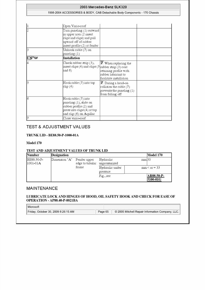
TEST AND ADJUSTMENT VALUES, GAP DIMENSIONS AT HOODS, DOORS AND COVERS
tubular frame Pressurizedhydraulic system
mm< or = 33
Fig., see AR88.50-P-5100-01G
Number Designation Model 170
BA88.50-P-1007-01A Bolt, striker eye totubular frame
Nm 10
BA88.50-P-1008-01A Bolt, striker to tubularframe Nm 10
BA88.50-P-1009-01A Bolt, hinge bracket totrunk lid
Nm 25
Number Designation Model 170
BA77.37-P-1001-01A
Emergency actuationvalve (N) onhydraulic unit
Nm 3
Fig., see AR77.50-P-3100G
Number Designation Model 170
BA77.33-P-1003-01A Bolts, catch on tubularframe in trunk
Nm 8
BA77.33-P-1004-01A Bolts, catch socket oncatch, tubular frame intrunk
Nm 8
Number Designation Model 170
BE60.00-P-1003-01A
Gap dimension Trunk lid to topof rear fender
Dimension "F" mm -

8/11/2019 BODY COMPONENTS.pdf
http://slidepdf.com/reader/full/body-componentspdf 53/105
Press trunk lid closed carefully, do not slam!
2003 Mercedes-Benz SLK320
1998-2004 ACCESSORIES & BODY, CAB Detachable Body Components - 170 Chassis

8/11/2019 BODY COMPONENTS.pdf
http://slidepdf.com/reader/full/body-componentspdf 54/105
Press trunk lid closed carefully, do not slam!
5. Check chalk imprint on rubber buffers.6. Adjust rubber buffers in increments until chalk marks uniform on both sides.
Check body transitions and closing forces on trunk lid permanently
Fig. 58: Identifying Contact Surface Of Rubber Buffer On Hinge Lever
7. Close locknut on rubber buffer (7)
8. Check adjustment of trunk lid when Vario roof is closed
Fig. 59: Identifying Locknut On Rubber Buffer
Adjust side stops on trunk lid - AR88.50-P-5200-02G
Test and adjustment values, gap dimensions at hoods, doors and covers
Number Designation Model 170
BE60.00-P-1003-01A
Gap dimension Trunk lid to topof rear fender
Dimension "F" mm -
Trunk lid to bottom of rearfender
Dimension "M" mm-
Trunk lid to rearfender
Dimension "F" mm 5.0 (+1/-0)
Trunk lid to Dimension "M" mm 5.0 (+1/-0)
2003 Mercedes-Benz SLK320
1998-2004 ACCESSORIES & BODY, CAB Detachable Body Components - 170 Chassis

8/11/2019 BODY COMPONENTS.pdf
http://slidepdf.com/reader/full/body-componentspdf 55/105
Fig. 60: Identifying Feeler Gage (129 589 03 21 00)
1. Loosen mounting bolts on stops (8) and move stops completely toward inside
2. Coat stops (9) in trunk lid opening with chalk
3. Close trunk lid
Press trunk lid carefully backwards, do not slam!
Fig. 61: Identifying Mounting Bolts On Stops
4. Check chalk imprint on stops (8)
5. Adjust stops in increments toward outside until chalk marks uniform on both sides.
Check body transitions, gaps and closing forces on trunk lid permanently.
taillamp( )
Trunk lid to bumper
Dimension "V" mm 8.0 (± 0.5)
Rear fender totaillamp
Dimension "U" mm 3.0 (± 0.5)
Fig., see AR60.00-P-0700-01G
2003 Mercedes-Benz SLK320
1998-2004 ACCESSORIES & BODY, CAB Detachable Body Components - 170 Chassis
8/11/2019 BODY COMPONENTS.pdf
http://slidepdf.com/reader/full/body-componentspdf 56/105
Fig. 62: Identifying Stops In Trunk Lid Opening
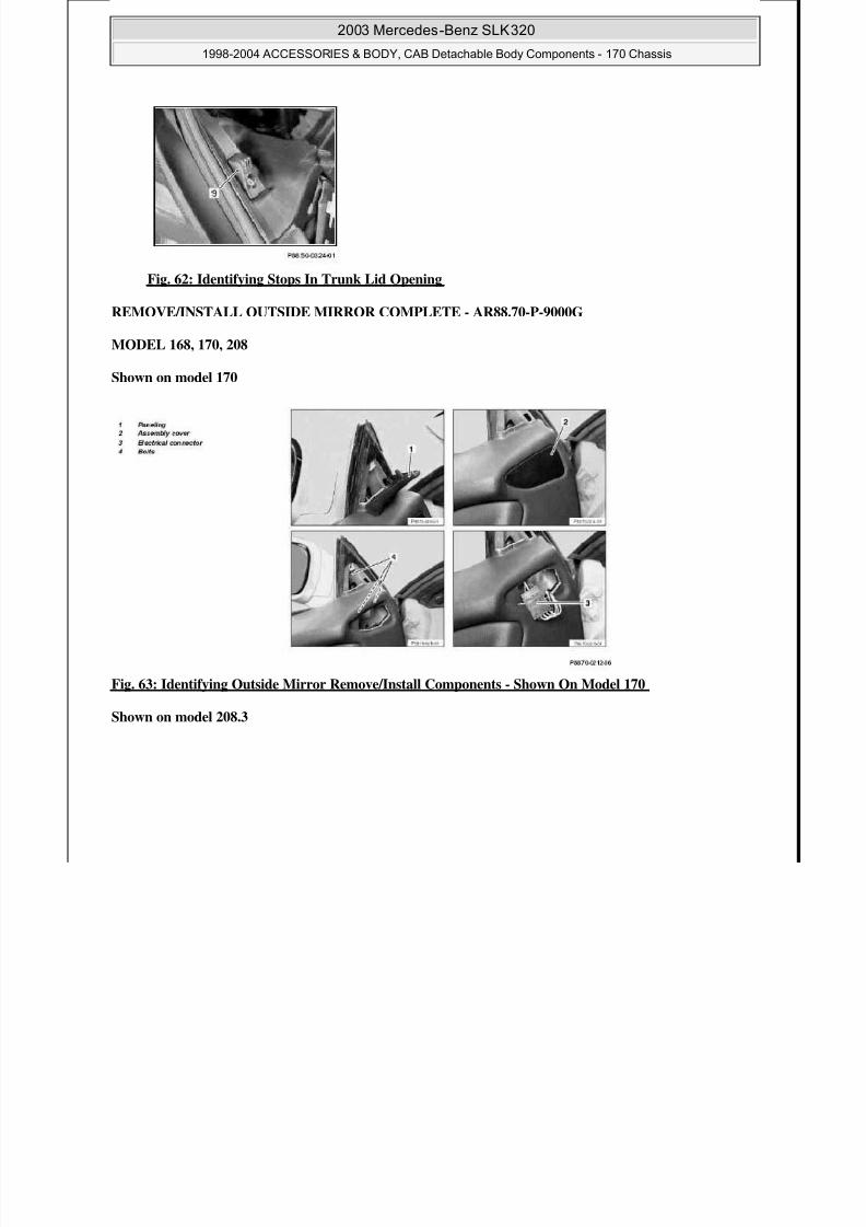
REMOVE/INSTALL OUTSIDE MIRROR COMPLETE - AR88.70-P-9000G
MODEL 168, 170, 208
Shown on model 170
Fig. 63: Identifying Outside Mirror Remove/Install Components - Shown On Model 170
Shown on model 208.3
2003 Mercedes-Benz SLK320
1998-2004 ACCESSORIES & BODY, CAB Detachable Body Components - 170 Chassis

8/11/2019 BODY COMPONENTS.pdf
http://slidepdf.com/reader/full/body-componentspdf 57/105
Fig. 64: Identifying Outside Mirror Remove/Install Components - Shown On Model 208.3
Shown on model 168
Fig. 65: Identifying Outside Mirror Remove/Install Components - Shown On Model 168
Remove/Install
1 Press paneling (1) off with
long wedge
Fig. 66
2.1 Remove door lining fromfront door
Only on model 208.3, if adoor liner is installedwithout assembly cover(2).
AR72.10-P-1000K
2.2 Press assembly cover (2)off with plastic wedge
Only on model 208.3, ifdoor liner is installedwith assembly cover (2)and on model 170.
3 Separate electricalconnection (3)
4 Unscrew bolts (4) and
remove outside mirror
2003 Mercedes-Benz SLK320
1998-2004 ACCESSORIES & BODY, CAB Detachable Body Components - 170 Chassis
8/11/2019 BODY COMPONENTS.pdf
http://slidepdf.com/reader/full/body-componentspdf 58/105
Fig. 66: Identifying Long Wedge (115 589 03 59 00)
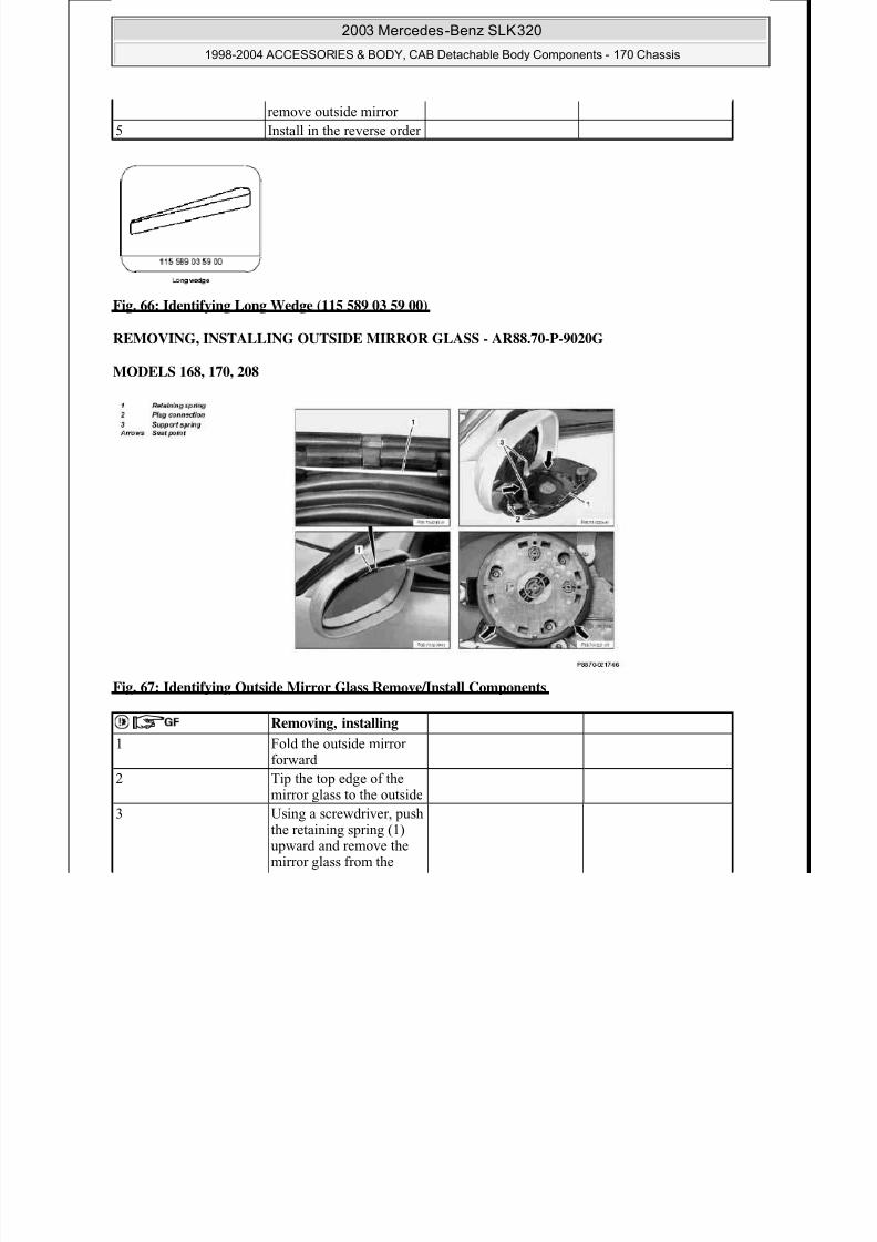
REMOVING, INSTALLING OUTSIDE MIRROR GLASS - AR88.70-P-9020G
MODELS 168, 170, 208
Fig. 67: Identifying Outside Mirror Glass Remove/Install Components
5 Install in the reverse order
Removing, installing
1 Fold the outside mirrorforward
2 Tip the top edge of the
mirror glass to the outside
3 Using a screwdriver, pushthe retaining spring (1)upward and remove themirror glass from the
drive
4 Di (2)
2003 Mercedes-Benz SLK320
1998-2004 ACCESSORIES & BODY, CAB Detachable Body Components - 170 Chassis

8/11/2019 BODY COMPONENTS.pdf
http://slidepdf.com/reader/full/body-componentspdf 59/105
REMOVING AND INSTALLING OUTSIDE REARVIEW MIRROR COVER - AR88.70-P-9040G
MODEL 168, 170, 208
Shown on model 170
Fig. 68: Identifying Outside Rearview Mirror Cover Remove/Install Components - Shown On Model 170
Shown on model 168
Fig. 69: Identifying Outside Rearview Mirror Cover Remove/Install Components - Shown On Model 168
4 Disconnect connector (2)
5 Install in the reverse order Start with the bottomside of the mirror glassand work your wayupward, paying attentionto the support spring (3)and seat point (arrows)

8/11/2019 BODY COMPONENTS.pdf
http://slidepdf.com/reader/full/body-componentspdf 60/105
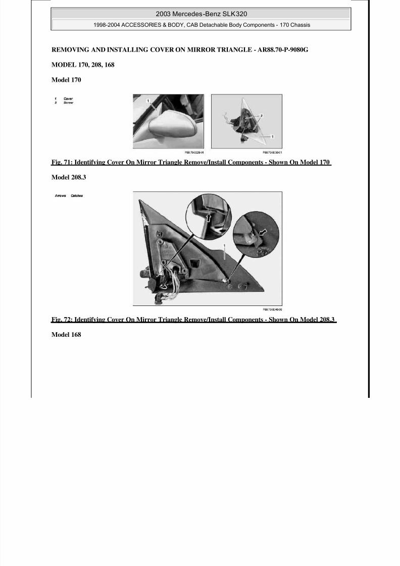
REMOVING AND INSTALLING COVER ON MIRROR TRIANGLE - AR88.70-P-9080G
2003 Mercedes-Benz SLK320
1998-2004 ACCESSORIES & BODY, CAB Detachable Body Components - 170 Chassis
8/11/2019 BODY COMPONENTS.pdf
http://slidepdf.com/reader/full/body-componentspdf 61/105
MODEL 170, 208, 168
Model 170
Fig. 71: Identifying Cover On Mirror Triangle Remove/Install Components - Shown On Model 170
Model 208.3
Fig. 72: Identifying Cover On Mirror Triangle Remove/Install Components - Shown On Model 208.3
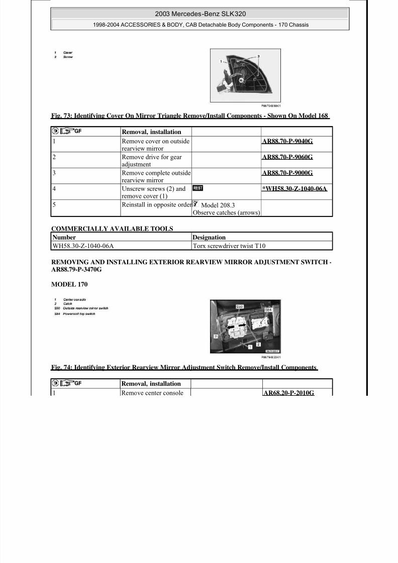
Model 168
2003 Mercedes-Benz SLK320
1998-2004 ACCESSORIES & BODY, CAB Detachable Body Components - 170 Chassis
8/11/2019 BODY COMPONENTS.pdf
http://slidepdf.com/reader/full/body-componentspdf 62/105
Fig. 73: Identifying Cover On Mirror Triangle Remove/Install Components - Shown On Model 168
COMMERCIALLY AVAILABLE TOOLS
REMOVING AND INSTALLING EXTERIOR REARVIEW MIRROR ADJUSTMENT SWITCH -AR88.79-P-3470G
MODEL 170
Fig. 74: Identifying Exterior Rearview Mirror Adjustment Switch Remove/Install Components
Removal, installation
1 Remove cover on outsiderearview mirror
AR88.70-P-9040G
2 Remove drive for gearadjustment
AR88.70-P-9060G
3 Remove complete outsiderearview mirror
AR88.70-P-9000G
4 Unscrew screws (2) andremove cover (1)
*WH58.30-Z-1040-06A
5 Reinstall in opposite order Model 208.3Observe catches (arrows)
Number Designation
WH58.30-Z-1040-06A Torx screwdriver twist T10
Removal, installation
1 Remove center console AR68.20-P-2010G
(1)
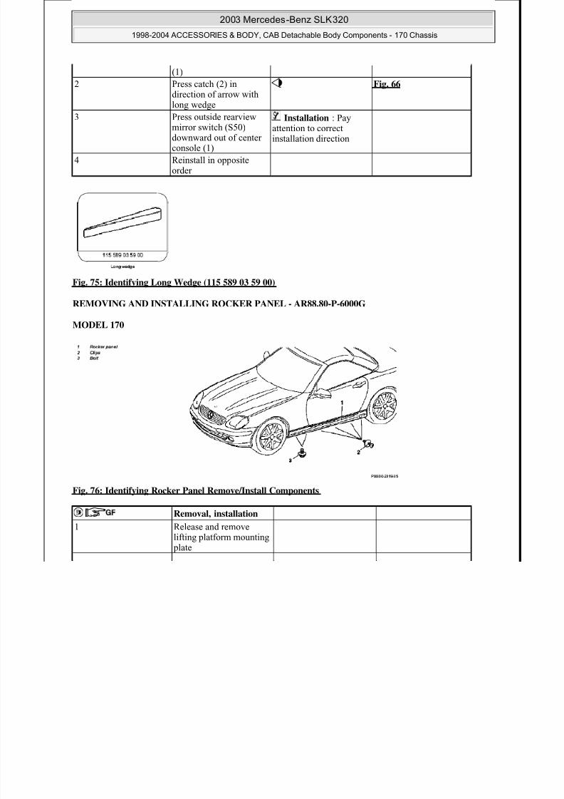
2 Press catch (2) in Fig. 66
2003 Mercedes-Benz SLK320
1998-2004 ACCESSORIES & BODY, CAB Detachable Body Components - 170 Chassis
8/11/2019 BODY COMPONENTS.pdf
http://slidepdf.com/reader/full/body-componentspdf 63/105
Fig. 75: Identifying Long Wedge (115 589 03 59 00)
REMOVING AND INSTALLING ROCKER PANEL - AR88.80-P-6000G
MODEL 170
Fig. 76: Identifying Rocker Panel Remove/Install Components
2 Press catch (2) in
direction of arrow withlong wedge
Fig. 66
3 Press outside rearviewmirror switch (S50)downward out of centerconsole (1)
Installation : Payattention to correctinstallation direction
4 Reinstall in oppositeorder
Removal, installation 1 Release and remove
lifting platform mounting plate

8/11/2019 BODY COMPONENTS.pdf
http://slidepdf.com/reader/full/body-componentspdf 64/105
8/11/2019 BODY COMPONENTS.pdf
http://slidepdf.com/reader/full/body-componentspdf 65/105

8/11/2019 BODY COMPONENTS.pdf
http://slidepdf.com/reader/full/body-componentspdf 66/105
8/11/2019 BODY COMPONENTS.pdf
http://slidepdf.com/reader/full/body-componentspdf 67/105
8/11/2019 BODY COMPONENTS.pdf
http://slidepdf.com/reader/full/body-componentspdf 68/105
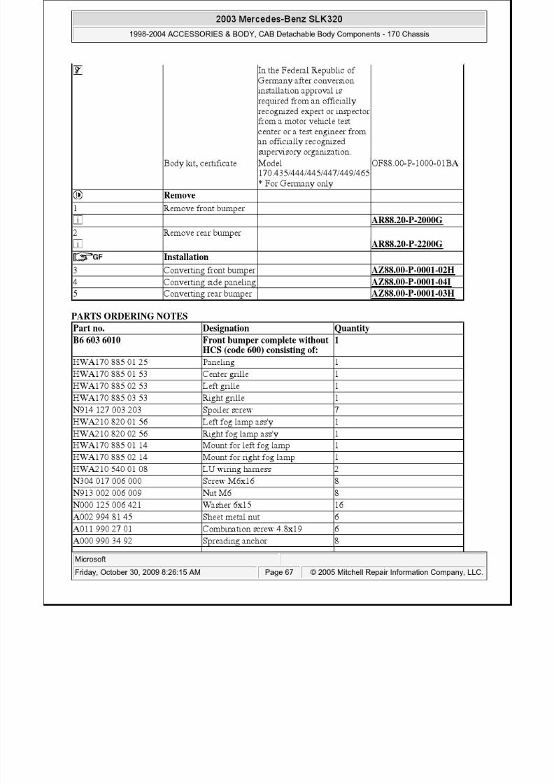
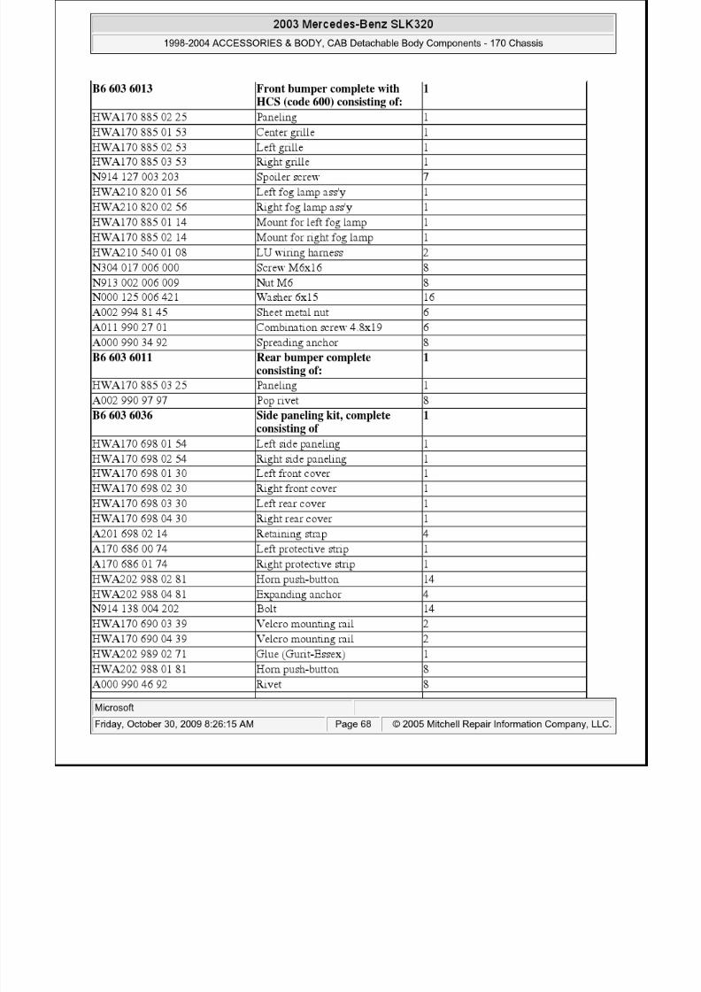
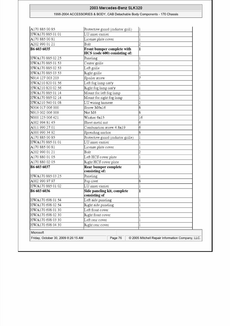
HWA170 690 01 62 Left cover strip ass'y 1
HWA170 690 02 62 Right cover strip ass'y 1
2003 Mercedes-Benz SLK320
1998-2004 ACCESSORIES & BODY, CAB Detachable Body Components - 170 Chassis

8/11/2019 BODY COMPONENTS.pdf
http://slidepdf.com/reader/full/body-componentspdf 69/105
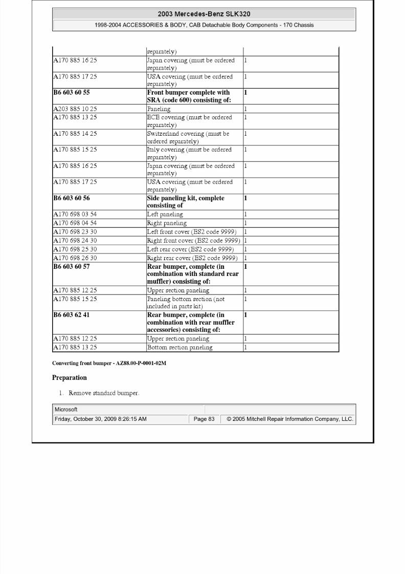
Converting front bumper - AZ88.00-P-0001-02H
Preparation
1. Remove standard bumper.
2. Disassemble standard bumper
3. Unscrew headlamps from inner carrier.
4. Remove side sliding arrests by drilling out pop rivets (A).
5. Remove side support panels by removing spreading rivets.
Fig. 80: Identifying Pop Rivets
6. Remove inner carrier and impact damper Press retaining lugs (B) for exterior surface out of anchoringwith screwdriver.
Assembly
7. Install inner carrier and impact damper8. Press retaining lugs (B) into anchoring at top and bottom
9. Anchor side support plates in exterior surface using spreading rivets.
A170 584 00 55 LU adhesive foil 1A170 997 01 86 Vehicle jack mount plug 4
2003 Mercedes-Benz SLK320
1998-2004 ACCESSORIES & BODY, CAB Detachable Body Components - 170 Chassis

8/11/2019 BODY COMPONENTS.pdf
http://slidepdf.com/reader/full/body-componentspdf 70/105
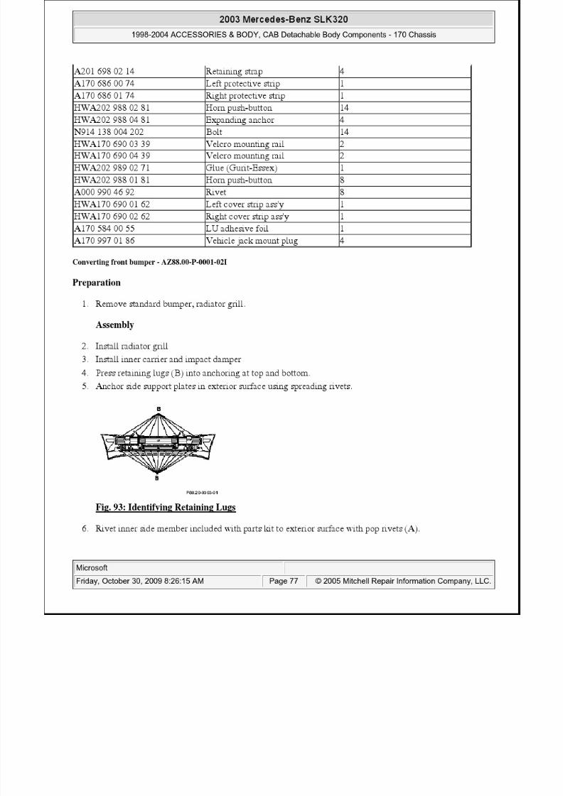
Fig. 81: Identifying Retaining Lugs
10. Rivet inner side member included with parts kit to exterior surface with pop rivets (A).
Fig. 82: Identifying Pop Rivets
11. Hook center grill in front apron and fasten with screws included (arrows).12. Insert outer grills.
Fig. 83: Identifying Center Grill Screws
13. Install headlamp: Fasten headlamp mount to original mounting points (C).
Fasten headlamp to mount (D) and to lug (E).
Insert adapter cable into headlamp.
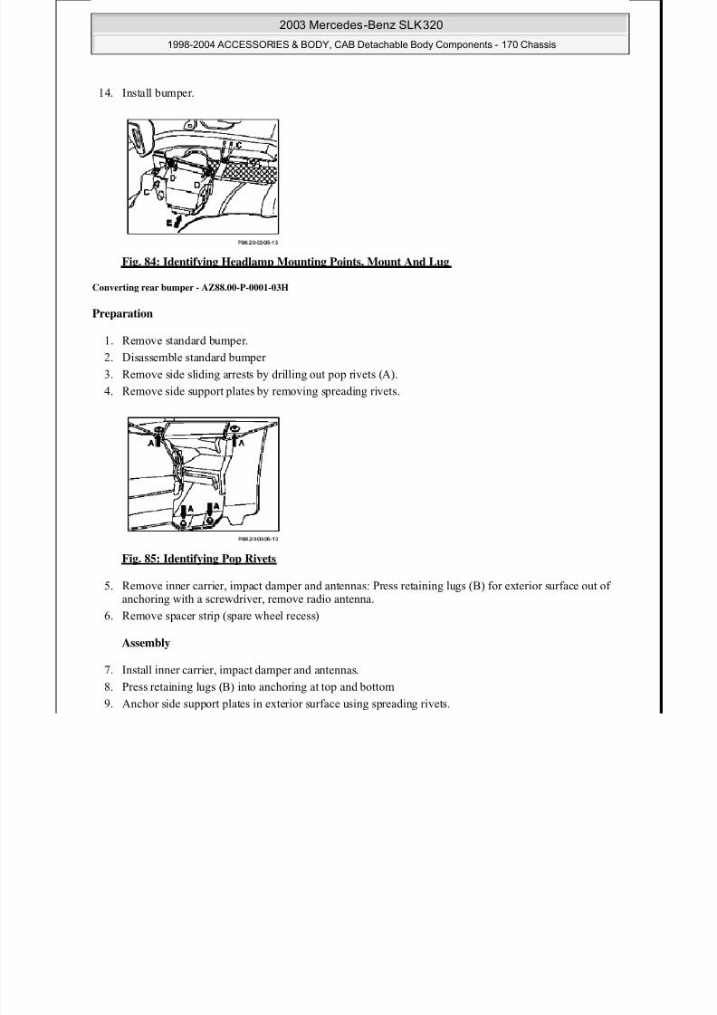
14. Install bumper.
2003 Mercedes-Benz SLK320
1998-2004 ACCESSORIES & BODY, CAB Detachable Body Components - 170 Chassis
8/11/2019 BODY COMPONENTS.pdf
http://slidepdf.com/reader/full/body-componentspdf 71/105
Fig. 84: Identifying Headlamp Mounting Points, Mount And Lug
Converting rear bumper - AZ88.00-P-0001-03H
Preparation
1. Remove standard bumper.
2. Disassemble standard bumper
3. Remove side sliding arrests by drilling out pop rivets (A).
4. Remove side support plates by removing spreading rivets.
Fig. 85: Identifying Pop Rivets
5. Remove inner carrier, impact damper and antennas: Press retaining lugs (B) for exterior surface out ofanchoring with a screwdriver, remove radio antenna.
6. Remove spacer strip (spare wheel recess)
Assembly
7. Install inner carrier, impact damper and antennas.
8. Press retaining lugs (B) into anchoring at top and bottom
9. Anchor side support plates in exterior surface using spreading rivets.
10. Rivet side sliding arrests in exterior surface.
11. Press radio antenna into lugs intended for this purpose and fasten with glue.
12 I ll i i d d f hi
2003 Mercedes-Benz SLK320
1998-2004 ACCESSORIES & BODY, CAB Detachable Body Components - 170 Chassis

8/11/2019 BODY COMPONENTS.pdf
http://slidepdf.com/reader/full/body-componentspdf 72/105
12. Install spacer strip on stay intended for this purpose.
13. Install bumper.
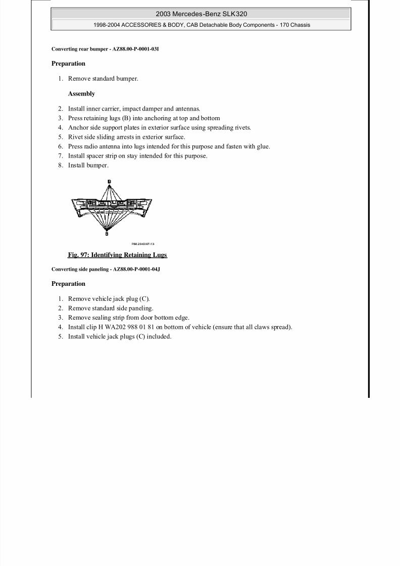
Fig. 86: Identifying Retaining Lugs
Converting side paneling - AZ88.00-P-0001-04I
Preparation
1. Remove sealing strip from door bottom edge.
2. Loosen sealing strips (A) and (B) from mounting elements with assembly wedge.
3. Remove mounting grommets on front and rear fender.
Fig. 87: Identifying Sealing Strips On Mounting Elements
4. Loosen sealing strip (C) from mounting elements with assembly wedge and remove snaps fromlongitudinal member.
2003 Mercedes-Benz SLK320
1998-2004 ACCESSORIES & BODY, CAB Detachable Body Components - 170 Chassis
8/11/2019 BODY COMPONENTS.pdf
http://slidepdf.com/reader/full/body-componentspdf 73/105
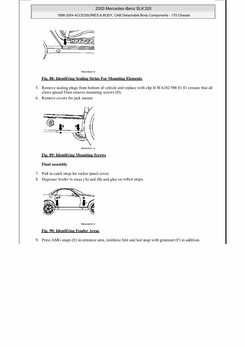
Fig. 88: Identifying Sealing Strips For Mounting Elements
5. Remove sealing plugs from bottom of vehicle and replace with clip H WA202 988 01 81 (ensure that allclaws spread Then remove mounting screws (D).
6. Remove covers for jack mount.
Fig. 89: Identifying Mounting Screws
Final assembly
7. Pull in catch strap for rocker panel cover.
8. Degrease fender in areas (A) and (B) and glue on tufted strips.
Fig. 90: Identifying Fender Areas
9. Press AMG snaps (E) in entrance area, reinforce first and last snap with grommet (F) in addition.

8/11/2019 BODY COMPONENTS.pdf
http://slidepdf.com/reader/full/body-componentspdf 74/105

8/11/2019 BODY COMPONENTS.pdf
http://slidepdf.com/reader/full/body-componentspdf 75/105
8/11/2019 BODY COMPONENTS.pdf
http://slidepdf.com/reader/full/body-componentspdf 76/105
8/11/2019 BODY COMPONENTS.pdf
http://slidepdf.com/reader/full/body-componentspdf 77/105
2003 Mercedes-Benz SLK320
1998-2004 ACCESSORIES & BODY, CAB Detachable Body Components - 170 Chassis

8/11/2019 BODY COMPONENTS.pdf
http://slidepdf.com/reader/full/body-componentspdf 78/105
Fig. 94: Identifying Pop Rivets
7. Hook center grill in front apron and fasten with screws included (arrows).
8. Insert outer grills.
Fig. 95: Identifying Center Grill Screws
9. Install headlamp:
Fasten headlamp mount to original mounting points (C).
Fasten headlamp to mount (D) and to lug (E).
Insert adapter cable into headlamp.
10. Install bumper.
Fig. 96: Identifying Headlamp Mounting Points, Mount And Lug
8/11/2019 BODY COMPONENTS.pdf
http://slidepdf.com/reader/full/body-componentspdf 79/105
2003 Mercedes-Benz SLK320
1998-2004 ACCESSORIES & BODY, CAB Detachable Body Components - 170 Chassis
8/11/2019 BODY COMPONENTS.pdf
http://slidepdf.com/reader/full/body-componentspdf 80/105
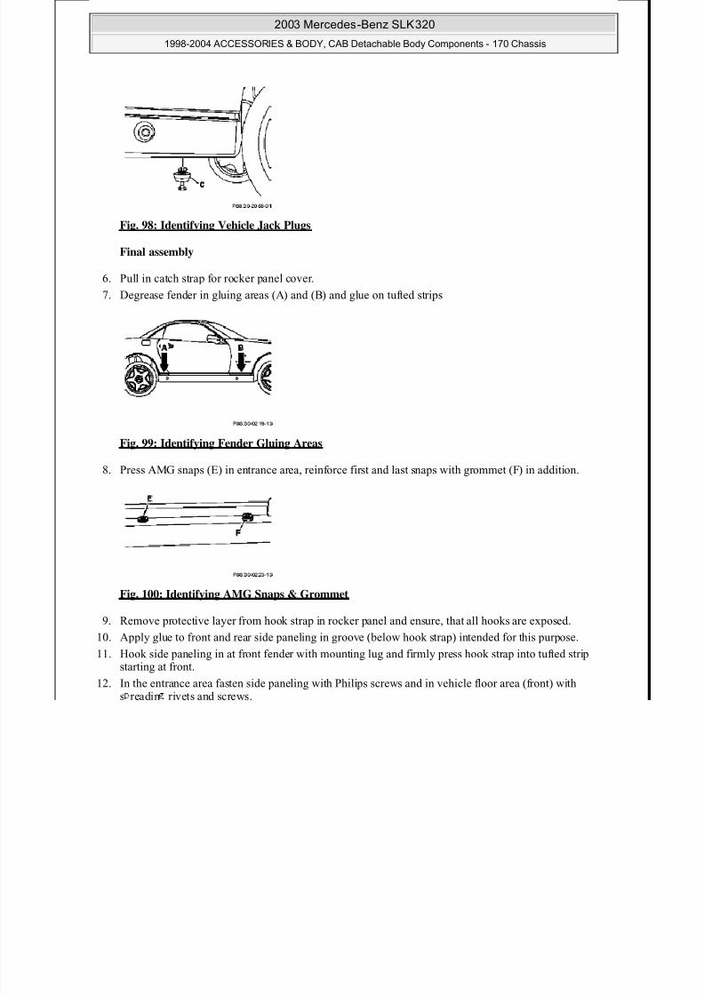
Fig. 98: Identifying Vehicle Jack Plugs
Final assembly
6. Pull in catch strap for rocker panel cover.
7. Degrease fender in gluing areas (A) and (B) and glue on tufted strips
Fig. 99: Identifying Fender Gluing Areas
8. Press AMG snaps (E) in entrance area, reinforce first and last snaps with grommet (F) in addition.
Fig. 100: Identifying AMG Snaps & Grommet
9. Remove protective layer from hook strap in rocker panel and ensure, that all hooks are exposed.
10. Apply glue to front and rear side paneling in groove (below hook strap) intended for this purpose.
11. Hook side paneling in at front fender with mounting lug and firmly press hook strap into tufted stripstarting at front.
12. In the entrance area fasten side paneling with Philips screws and in vehicle floor area (front) withs readin rivets and screws.

8/11/2019 BODY COMPONENTS.pdf
http://slidepdf.com/reader/full/body-componentspdf 81/105

8/11/2019 BODY COMPONENTS.pdf
http://slidepdf.com/reader/full/body-componentspdf 82/105
8/11/2019 BODY COMPONENTS.pdf
http://slidepdf.com/reader/full/body-componentspdf 83/105

8/11/2019 BODY COMPONENTS.pdf
http://slidepdf.com/reader/full/body-componentspdf 84/105
2003 Mercedes-Benz SLK320
1998-2004 ACCESSORIES & BODY, CAB Detachable Body Components - 170 Chassis
8/11/2019 BODY COMPONENTS.pdf
http://slidepdf.com/reader/full/body-componentspdf 85/105
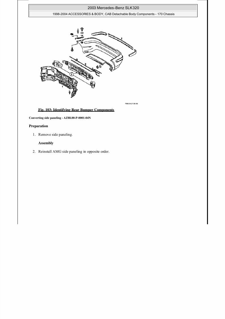
Fig. 103: Identifying Rear Bumper Components
Converting side paneling - AZ88.00-P-0001-04N
Preparation
1. Remove side paneling.
Assembly
2. Reinstall AMG side paneling in opposite order.
2003 Mercedes-Benz SLK320
1998-2004 ACCESSORIES & BODY, CAB Detachable Body Components - 170 Chassis

8/11/2019 BODY COMPONENTS.pdf
http://slidepdf.com/reader/full/body-componentspdf 86/105
Fig. 104: Identifying AMG Side Paneling Components
Retrofitting adapter on towing eye - AZ88.00-P-0001-05A
TOWING EYE
1. Install adapter (1) to towing eye.
2. Lay towing eye ring (3) into trunk with jack.
3. For towing see operating instructions.
Number Designation Model 170 with code772
BA00.60-P-1001-01A Screw for adapter ontowing eye
NM 67 (± 2)
2003 Mercedes-Benz SLK320
1998-2004 ACCESSORIES & BODY, CAB Detachable Body Components - 170 Chassis
8/11/2019 BODY COMPONENTS.pdf
http://slidepdf.com/reader/full/body-componentspdf 87/105
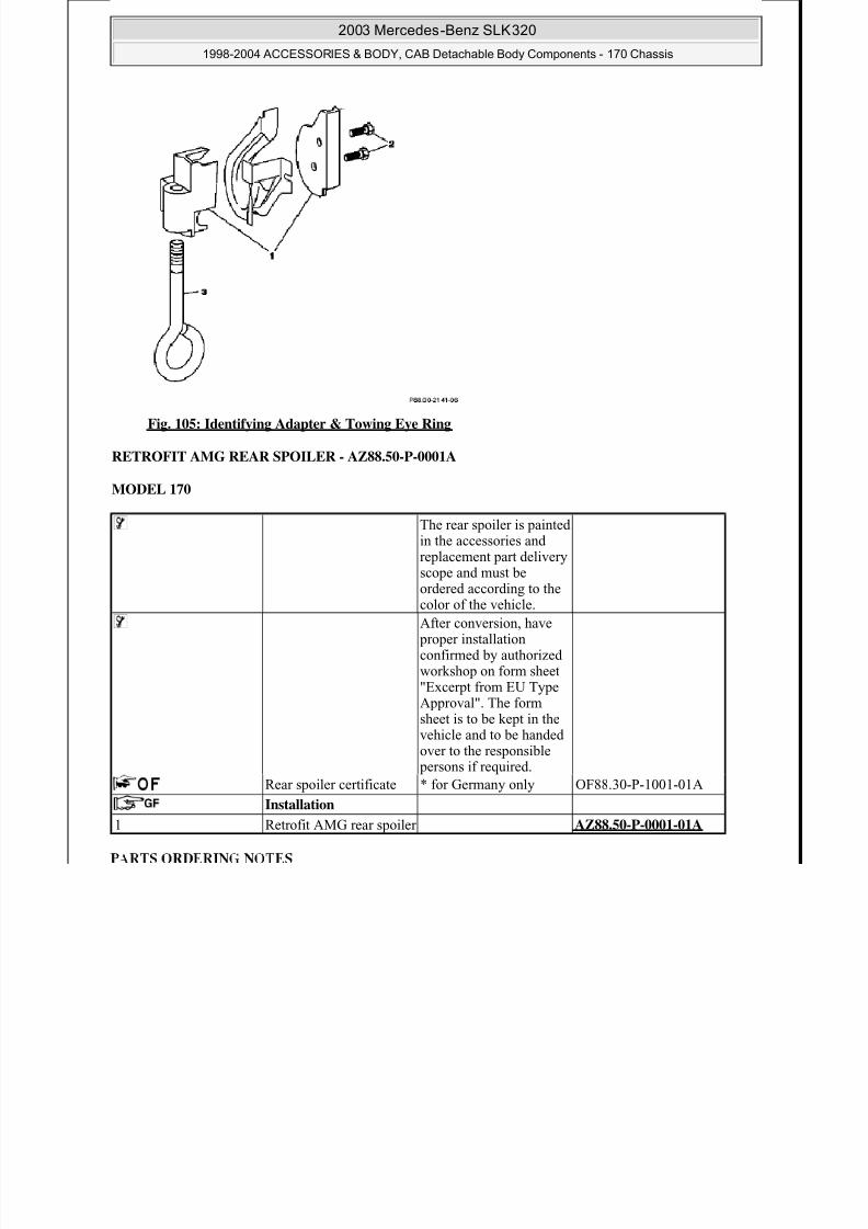
Fig. 105: Identifying Adapter & Towing Eye Ring
RETROFIT AMG REAR SPOILER - AZ88.50-P-0001A
MODEL 170
The rear spoiler is painted
in the accessories andreplacement part deliveryscope and must beordered according to thecolor of the vehicle.
After conversion, have proper installationconfirmed by authorized
workshop on form sheet"Excerpt from EU TypeApproval". The formsheet is to be kept in thevehicle and to be handedover to the responsible persons if required.
Rear spoiler certificate * for Germany only OF88.30-P-1001-01A
Installation
1 Retrofit AMG rear spoiler AZ88.50-P-0001-01A
Retrofit AMG rear spoiler - AZ88.50-P-0001-01A
Part no. Designation Quantity
A170 790 0088 AMG rear spoiler (order with paintcode, see EPC BM 170.466)
1
2003 Mercedes-Benz SLK320
1998-2004 ACCESSORIES & BODY, CAB Detachable Body Components - 170 Chassis

8/11/2019 BODY COMPONENTS.pdf
http://slidepdf.com/reader/full/body-componentspdf 88/105
Only install the AMG rear spoiler in a closed room with a minimum temperature of 20° Celsius.
Clean the gluing surfaces to remove all dust and grease before cementing!
Mark dimensions
1. Mark a distance of 736 mm from the extreme edge of the trunk lid to the front edge of the spoiler on bothsides of the vehicle (see arrow).
The dimensions must be exact!
Mark the measured points using adhesive tape (TESA crepe or similar).
Fig. 106: Measuring Distance From Extreme Edge Of Trunk Lid To Front Edge Of Spoiler
Mark dimensions
2. Mark a distance of 509 mm from the center of the trunk lid edge to the edge of the spoiler (see arrow).
The dimensions must be exact!
Mark the measured points using adhesive tape (TESA crepe or similar).
2003 Mercedes-Benz SLK320
1998-2004 ACCESSORIES & BODY, CAB Detachable Body Components - 170 Chassis

8/11/2019 BODY COMPONENTS.pdf
http://slidepdf.com/reader/full/body-componentspdf 89/105
Fig. 107: Measuring Distance From Center Of Trunk Lid Edge To Edge Of Spoiler
Preparing rear spoiler for installation
3. Pull back protective foil (1) for a length of approx. 100 mm at both extreme ends, top and bottom.
4. Pull off protective foil (2) for a length of approx. 100 mm to both sides of the center.
5. Pull off protective foil (3) from the short length of adhesive tape entirely.
6. Apply glue to marked points (arrows between pieces of adhesive tape)
Fig. 108: Identifying Protective Foil
Fig. 109: Identifying Protective Foils
Attaching rear spoiler
7. Ali n the rear s oiler with res ect to the brake lam and osition with the ex osed foil on the 509 mm
marking.
2003 Mercedes-Benz SLK320
1998-2004 ACCESSORIES & BODY, CAB Detachable Body Components - 170 Chassis
8/11/2019 BODY COMPONENTS.pdf
http://slidepdf.com/reader/full/body-componentspdf 90/105
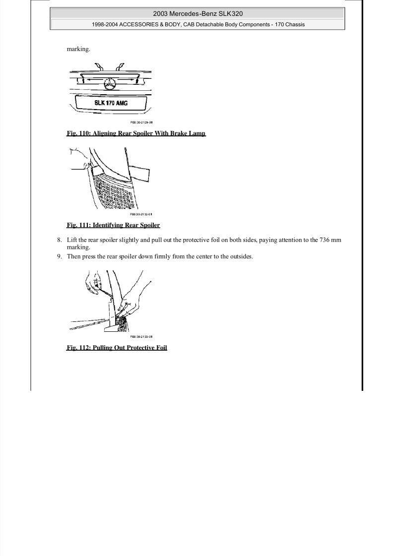
Fig. 110: Aligning Rear Spoiler With Brake Lamp
Fig. 111: Identifying Rear Spoiler
8. Lift the rear spoiler slightly and pull out the protective foil on both sides, paying attention to the 736 mm
marking.
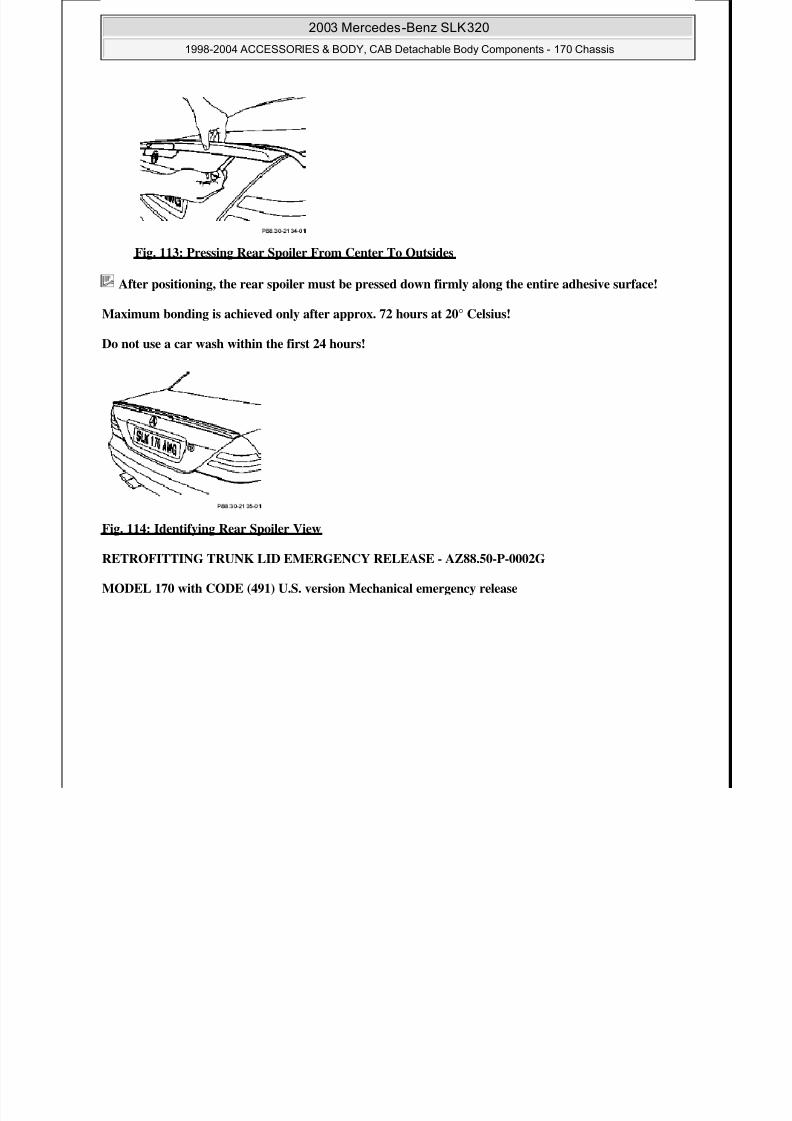
9. Then press the rear spoiler down firmly from the center to the outsides.
Fig. 112: Pulling Out Protective Foil
8/11/2019 BODY COMPONENTS.pdf
http://slidepdf.com/reader/full/body-componentspdf 91/105
2003 Mercedes-Benz SLK320
1998-2004 ACCESSORIES & BODY, CAB Detachable Body Components - 170 Chassis
8/11/2019 BODY COMPONENTS.pdf
http://slidepdf.com/reader/full/body-componentspdf 92/105
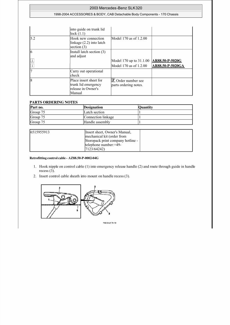
Fig. 115: Identifying Trunk Lid Emergency Release Retrofit Components
The parts for retrofittingthe trunk lid emergencyrelease are given in the part documents (GroupKG 75 trunk lid).
Removing 1 Remove latch section (3) The latch section (3) is
replaced. Do not removetrunk lid lock (1.1) or(1.2)!
Model 170 up to 31.1.00 AR88.50-P-5020G
Model 170 as of 1.2.00 AR88.50-P-5020GA
2.1 Remove connectionlinkage (2.2) Model 170 as of1.2.00.The connection linkage(2.2) is replaced.
Installation
3 Retrofit control cable (4) AZ88.50-P-0002-04G
4 Position latch section (3)at its installation position
on the trunk lid
5.1 First insert connectionshaft (2.1) into guide onlatch section (3) and then
Model 170 up to 31.1.00
into guide on trunk lidlock (1.1)
5.2 Hook new connection
linkage (2.2) into latchsection (3)
Model 170 as of 1.2.00
6 Install latch section (3)
2003 Mercedes-Benz SLK320
1998-2004 ACCESSORIES & BODY, CAB Detachable Body Components - 170 Chassis
8/11/2019 BODY COMPONENTS.pdf
http://slidepdf.com/reader/full/body-componentspdf 93/105
PARTS ORDERING NOTES
Retrofitting control cable - AZ88.50-P-0002-04G
1. Hook nipple on control cable (1) into emergency release handle (2) and route through guide in handlerecess (3).
2. Insert control cable sheath into mount on handle recess (3).
6 Install latch section (3)and adjust
Model 170 up to 31.1.00 AR88.50-P-5020G
Model 170 as of 1.2.00 AR88.50-P-5020GA
7 Carry out operational
check
8 Place insert sheet fortrunk lid emergencyrelease in Owner'sManual
Order number see parts ordering notes.
Part no. Designation Quantity
Group 75 Latch section 1
Group 75 Connection linkage 1
Group 75 Handle assembly 1
6515955913 Insert sheet, Owner's Manual,mechanical kit (order fromStoropack print company hotline -
telephone number:+49-7123/64242)
Fig. 116: Identifying Control Cable, Emergency Release Handle & Handle Recess
3. Route control cable (1) through hollow space in trunk lid to installation position for locking part.
4. Clip handle recess (3) into cutout on trunk lid.
2003 Mercedes-Benz SLK320
1998-2004 ACCESSORIES & BODY, CAB Detachable Body Components - 170 Chassis
8/11/2019 BODY COMPONENTS.pdf
http://slidepdf.com/reader/full/body-componentspdf 94/105
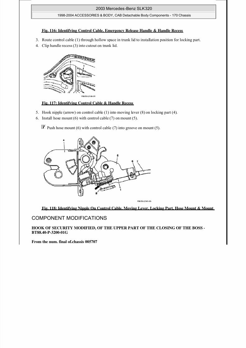
Fig. 117: Identifying Control Cable & Handle Recess
5. Hook nipple (arrow) on control cable (1) into moving lever (8) on locking part (4).
6. Install hose mount (6) with control cable (7) on mount (5).
Push hose mount (6) with control cable (7) into groove on mount (5).
Fig. 118: Identifying Nipple On Control Cable, Moving Lever, Locking Part, Hose Mount & Mount
COMPONENT MODIFICATIONS
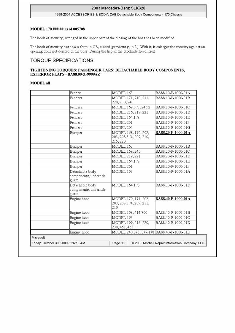
HOOK OF SECURITY MODIFIED, OF THE UPPER PART OF THE CLOSING OF THE BOSS -BT88.40-P-3200-01G
From the num. final of.chassis 005707
8/11/2019 BODY COMPONENTS.pdf
http://slidepdf.com/reader/full/body-componentspdf 95/105

8/11/2019 BODY COMPONENTS.pdf
http://slidepdf.com/reader/full/body-componentspdf 96/105

8/11/2019 BODY COMPONENTS.pdf
http://slidepdf.com/reader/full/body-componentspdf 97/105

8/11/2019 BODY COMPONENTS.pdf
http://slidepdf.com/reader/full/body-componentspdf 98/105
8/11/2019 BODY COMPONENTS.pdf
http://slidepdf.com/reader/full/body-componentspdf 99/105

8/11/2019 BODY COMPONENTS.pdf
http://slidepdf.com/reader/full/body-componentspdf 100/105

8/11/2019 BODY COMPONENTS.pdf
http://slidepdf.com/reader/full/body-componentspdf 101/105
8/11/2019 BODY COMPONENTS.pdf
http://slidepdf.com/reader/full/body-componentspdf 102/105
8/11/2019 BODY COMPONENTS.pdf
http://slidepdf.com/reader/full/body-componentspdf 103/105
8/11/2019 BODY COMPONENTS.pdf
http://slidepdf.com/reader/full/body-componentspdf 104/105
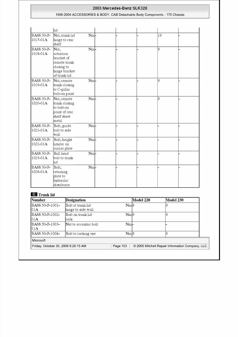
BA88.50-P-1022-01A
Bolt, height limiteron carrier plate
Nm - 4
BA88.50-P-1023-
01A
Ball head bolt to
trunk lid
Nm - -
BA88.50-P-1024-01A
Bolt, retaining plateto hydraulicdistributor
Nm - 2
2003 Mercedes-Benz SLK3201998-2004 ACCESSORIES & BODY, CAB Detachable Body Components - 170 Chassis

8/11/2019 BODY COMPONENTS.pdf
http://slidepdf.com/reader/full/body-componentspdf 105/105