boiler 1
DESCRIPTION
Presentation 1 of 2 on the design of Power BoilersTRANSCRIPT

1
Classification of Boilers
Boilers
By uses By pressure Firing method construction
Field erected
Shop assembled
stoker
cyclone
burners
Fluidized bed
Low pressure
High pressure
supercritical
utility
industrial
circulation
natural
Once through
forced
Slag removal
Wet bottom
Dry bottom
Fuel source
Waste heat
Oil/gas/solid

2
SteamFirst fire tube boiler-1769. water tube boiler-1804.1856 B&W designed a natural circulation unit.1921-steam pressure 450 psig,650F. 1924-550 psig,725FReheat unit in 1924. 1920 coal fired boilers. 1925-3150 kw boiler at 1200 psi,700F /700F. 1940s,industrial boilers. 1957 commercial operation of a boiler with steam pressure above 3208 psi.125 MW B&W unit delivered 675,000 lb/h at 4550 psi,1150F/1050/1000F.cast iron tubes used in 1900s,commercial process for hot finished seamless steel tubes.before 1930,riveting was used to join drum plates.1930-welded designs.1987-1300 MW universal pressure boilers at 3485 psi,1010F/1000F. 1960s-lot of sub critical utility boilers.
1970s-FBC-ability to reduce SO2 emissions.20 MW bubbling bed boiler.
STEAM IS THE WORKING FLUID IN POWER & PROCESS PLANTS High thermal capacity, high critical temperature, wide availability and non-toxic nature has served to maintain its dominant position as a working fluid.

3
Rankine Cycle

4
Rankine Cycle lossesIn a typical rankine cycle only about 35% of fuel energy is converted to electricity. 15% energy is lost due to flue gas losses, radiation loss and parasitic power. The Rankine cycle losses account for the remaining 50%. This is basically the energy in the steam at turbine exhaust. Although the energy in this steam is large,it is at such low pressure and temperature that it is useless.
The heat sink temperature limits an engine from achieving 100% conversion of heat to work. Second Law Efficiency=(2460-510)/2460 =79.3%If the source temperature is 500F instead of 2000F,the efficiency=(960-510)/960=46.9%
If the heat sink temperature goes up to 120F from 50F,the efficiency is only (960-580)/960=39.5%
If one could somehow directly use the heat source and heat sink,the efficiencies would be high as shown. However heat engines like today’s turbines need a medium to go between the heat source and the heat sink. Also maximum temperature limited by metallurgy,say 1050F and lowest temperature by pinch point at the heat sink and hence say 80F would be the lowest.Efficiency=(1510-540)/2460=39.4%

5
Boilers and Power GenerationModern fossil fuel fired stations use 1800 to 3500 psi cycles with steam temperature ranging from 950 to 1050 F. Reheat cycles are used due to improved cycle efficiency.
coaloilgasnuclearhydroother
Coal-55.5%,oil-4.2%,gas-9.4%, nuclear-20.5%, hydro-10%, other-.4%
US electricity generation-1990
Coal-44%,oil-10%,gas-8.5%,nuclear-17%,hydro-20%,other-.5%
Worldwide electricity generation-1988

6
Rankine Cycle EfficiencySimple cycle without superheat
Qa=heat added=hb-ha
Qr=heat rejected=hc-hd
PW=pump work=ha-hd
W=net work=hb-hc-PW
TE=Thermal efficiency=W/Qa
Regenerative reheat cycle with 2 fw heaters
Qa=(hc-ha)+(1-m1)(he-hd)
Qr=(1-m1-m2))(hg-hh)
W=(hc-hd)+(1-m1)(he-hf)+(1-m1-m2)(hf-hg)-PW
Thermal Efficiency=W/Qa
PW=(ha-hl)+(1-m1)(hk-hj)+(1-m1-m2)(hj-hh)

7
Open and closed cycle heatersIn an open feed water heater,steam mixes with the feed water.mixture leaves at steam temperature.In a closed feed water heater,the fluids don’t mix and can be at different pressures.Water leaves at less than steam temperature.
Open:simple,inexpensive but a pump is required to handle feed water at each stage.
Closed:complex,less effective but does not need a pump. Plants use both.

8
Development of Steam Parameters

9
Steam Parameters and Cycle Efficiency

10
Steam pressure vs Boiler type

11
Supercritical Steam cyclesThe first supercritical boiler(>3208 psig) was placed in service in 1957.Steam arrives at the turbine at 3500 psi and 1050F. It is expanded to 540 psi and reheated to 1050F and sent back.Power consumption of feed pumps is high.In a 2400 psi cycle,feed pump consumes about 2.5 % of turbine output. In a supercritical unit,it is about 5 %.However the improvement in thermal efficiency justifies this. About 4 % more power is generated in SC units compared to sub critical for similar plant parameters.
The boiler used for this application is a once through unit as there is no need for any circulation system.Capacity ranges from 300,000 lb/h to 10,000,000 lb/h. Steam temperature is controlled by coordinated firing and pumping rate. Reheater temperature is controlled by gas bypass dampers,gas recirculation,excess air or combination.Minimum flow is maintained in the furnace to avoid DNB. Furnace tubes could be straight or spiral wound.Spiral wound design increases the tube side velocity and provides cooling under all loads.It is also suitable for cycling and frequent startups.

12
Boiler Capacity vs Time
Capacity vs Period
0
500
1000
1500
2000
2500
3000
3500
4000
4500
5000
1950 1960 1970 1980 1990 2000
year
capa
city
,t/h
USA
FRG

13
Utility Boilers

14
Steam flood generator
Steam pressure ranges from 1500-3000 psig
Oil or gas fired mobile units . high TDS in water

15
3 pass dry back fire tube boiler

16
Oil/Gas fired wet back boiler
Note the turning section which is water cooled. There is no refractory there(at 2000 F ).Hence fewer maintenance problems compared to dry back boilers. Little more expensive.

17
Boiler HP conversionPackaged Fire tube boilers are traditionally purchased in terms of Boiler Horse Power. BHP refers to steam capacity of 34.5 lb of steam at atmospheric pressure with feed water at 212 F.However a boiler operates at different steam pressures and temperatures. Hence conversion between BHP and steam flow is necessary:
W=33475 BHP/DH where DH =enthalpy absorbed by steam=(hg-hf)+BD(hl-hf)
Hg,hl,hf=enthalpy of sat vapor,liquid and feed water,Btu/lb
W=steam flow,lb/h, BD=blow down,fraction
Example:A 500 BHP boiler generates sat steam at 125 psig with a 5% blow down with feed water at 230 F.1193,325,198 are the enthalpies of steam,liquid and feed water.
Hence W=500x33475/[1193-198+.05x(325-198)]=16,714 lb/h

18
Boiler Economizer Arrangement

19
D-type Boiler Arrangement

20
O-type Package boiler
Another variation of custom designed package boiler…
O-type design has an integral furnace and convection bank consisting of extended surfaces to minimize length and a horizontal gas flow economzier. If boiler width is a concern, this design is ideal.
Suitable for clean fuels as finned tubes are required for convection section.Superheater could be buried within convection bank if required.

21
D type Boiler Details

22
Boiler circulation systems

23
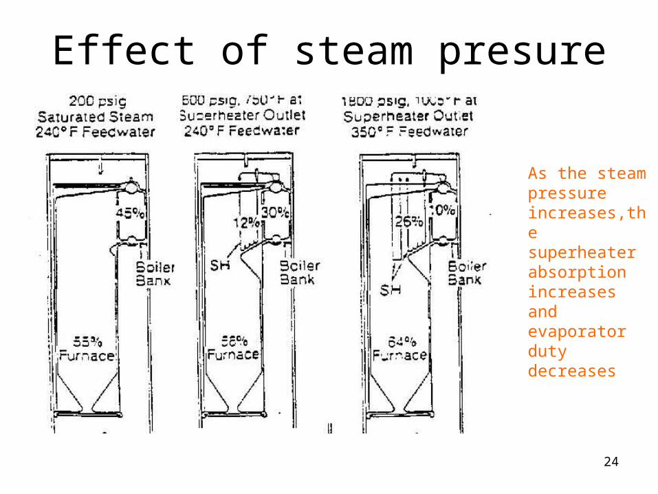
Energy Distribution in Boilers
As the steam pressure changes,so does the distribution of sensible,latent and superheat duties.
24
Effect of steam presure
As the steam pressure increases,the superheater absorption increases and evaporator duty decreases
25
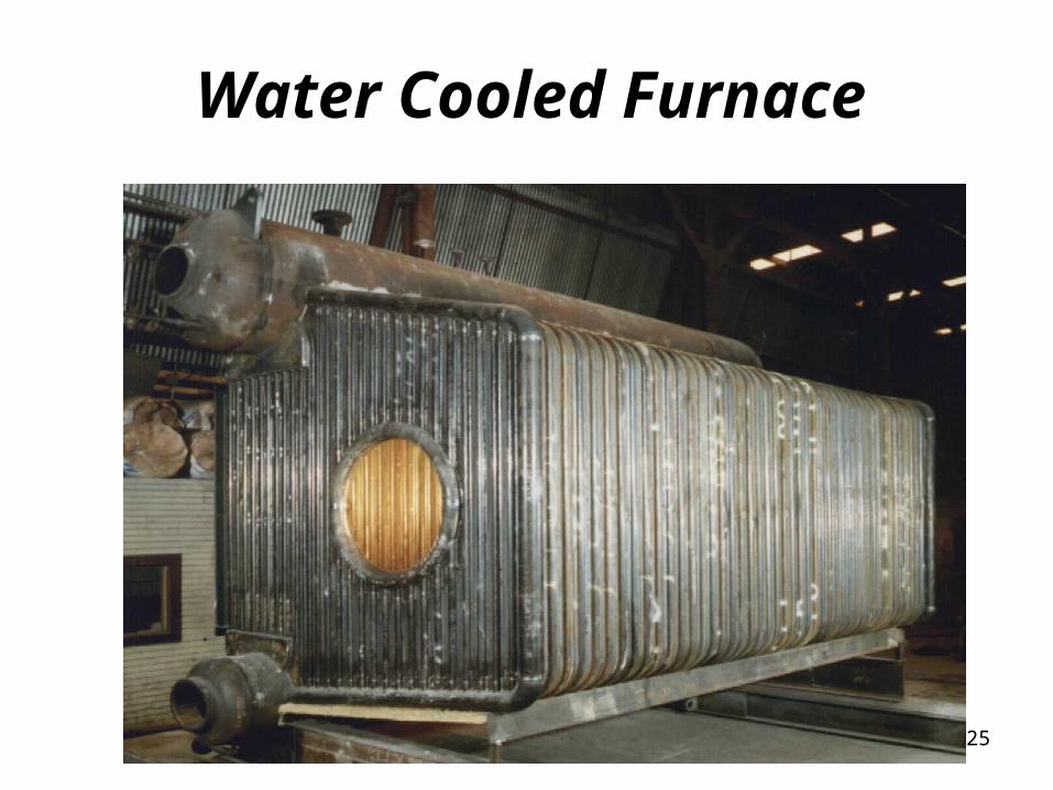
Water Cooled Furnace

26
Shop assembled boilers•Up to 300,000 lb/h steam
•1500 psig,1000F
•Pressurized furnace
•Single FD fan
•Steam temperature control
•Quick startup charactersitics
•Completely water cooled furnace
•Custom designed to minimize operating costs
•Economizer as heat recovery
•Oil or gas fired
Shipping limitations determine capacity
Can be built in modules
Solid fuels also fired

27
Limitations of Standard Boilers•Furnace designs developed decades ago when emissions was not a concern.With fuel,air staged Low-Nox burners,flame shapes are different and flame impingement on furnace walls a concern.
•Effect of excess air,FGR not optimally considered.15 % excess air,15 % FGR typical.This increases flue gas flow by 26 % and results in 60 % higher gas pressure drop if boiler design is not reconfigured.1 in wc additional gas pressure drop in a 100,000 lb/h = 5 to 7 kw.
•650 psig,750 F steam has enthalpy pickup of 1193 Btu/lb versus 1003 Btu/lb for 150 psig sat steam with 230 F water. The increase in duty of 19 % increases flue gas flow,43 % increase in gas pressure drop if boiler were not redesigned.Similarly deleting the economizer increases gas flow by 7-10 % and 15 to 20 % increase in gas pressure drop. In sum,Standard boiler is a compromised offering and is costly to operate in the long run,though lower in initial cost..A Custom designed boiler is the right choice !

28
Advantages of Completely water cooled Furnace
•Lower heat flux for a given volume,about 9 to 12 %
•Lower area heat release rate and hence lower NOx
•Absence of reradiation from refractory near the flame front,where most NOx formation occurs
•Lower excess air or FGR rates may be used due to less intense combustion process compared to a refractory lined furnace
•Furnace is leak proof and hence no leakage of gases to second pass,which results in larger CO formation and inefficiency
•No refractory maintenance concerns
•Startup rates can be faster as concerns with refractory breaking or cracking are absent
•No casing leaks or corrosion concerns
29
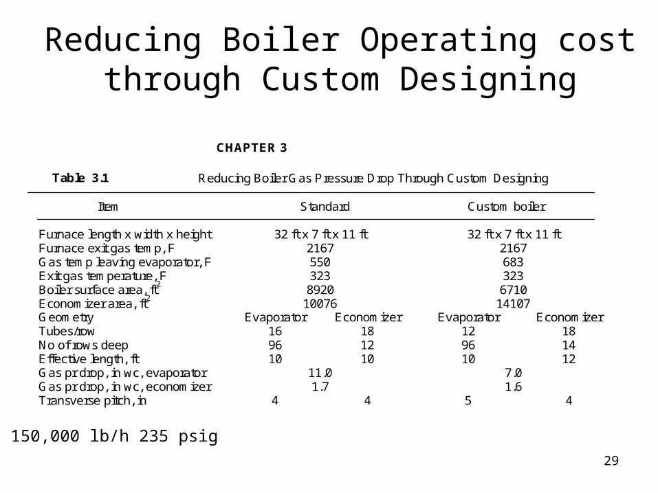
Reducing Boiler Operating cost through Custom Designing
CHAPTER 3
Table 3.1 Reducing Boiler Gas Pressure Drop Through Custom Designing
Item Standard Custom boiler
Furnace length x width x height 32 ft x 7 ft x 11 ft 32 ft x 7 ft x 11 ftFurnace exit gas temp, F 2167 2167Gas temp leaving evaporator, F 550 683Exit gas temperature, F 323 323Boiler surface area, ft2 8920 6710Economizer area, ft2 10076 14107Geometry Evaporator Economizer Evaporator EconomizerTubes/row 16 18 12 18No of rows deep 96 12 96 14Effective length, ft 10 10 10 12Gas pr drop, in wc, evaporator 11.0 7.0Gas pr drop, in wc, economizer 1.7 1.6Transverse pitch, in 4 4 5 4
150,000 lb/h 235 psig

30
Boiler Surface Area ComparisonsItem Boiler1 boiler2
HRR(Btu/ft3h) 90500 68700
HRR(Btu/ft2h) 148,900 116,500
Furnace len x width x ht 22x6x10 29x6x10
Furnace exit gas temp,F 2364 2255
Boiler exit gas temp,F 683 611
Economizer exit gas,F 315 315
Furnace proj area(duty) 802(36.6) 1026(40.4)
Boiler evap area(duty) 3972(53.7) 4760(52.1)
Eco surf(duty) 8384(10.5) 8550(8.3)
Evap tubes/row,no deep,len 11x66x9.5 10x87x9.5
Eco tubes/row,no deep,len 15x14x11 15x10x10
Eco fin geometry 3x.75x.05 ser 5x.75x.05 serr
Tr pitch evap/eco 4/4 4.375/4
100,000 lb/h 300 psig,230 F water,n.gas,10 % excess air back pr=7 in wc Eff=84.3 %
Boiler performance is the same in both cases,though surface areas differ!

31
Why Economizer and not an air heater?
Economizers are widely used in package boilers instead of air heaters as heat recovery equipment for the following reasons.
•Combustion temperature is increased if an air heater is used,thus increasing NOx
•Gas/air side pressure drops are much higher with an air heater say 4 to 5 in wc vs 1 in wc for an economizer
•Furnace heat flux is also higher if an air heater is used.
•Air heater may be required on boilers using difficult to burn fuels such as coal and low Btu fuels
•Corrosion potential is higher as tubes operate at lower temperatures

32
Performance without economizerProblem:If we look at the performance at say 100 %,gas temperature leaving evaporator is 739 F.If the economizer is removed from service,will the gas temperature be still 739 F at the same steam generation rate? Will the gas pressure drop be lower?
Solution:The answer is no. The boiler efficiency drops by at least (739-327)/40=10.3 %. Hence the new efficiency will be less than 83.66-10.3=73.36 %.
2.The boiler fuel and flue gas quantity will increase by the same ratio. The new heat input=(118.71/.733)=161.8 MM Btu/h vs (118.71/.8366)=141.9 MM Btu/h. hence the air flow, flue gas flow will be higher by 161.8/141.9=1.14 or 14 % or 142,800 lb/h vs 125246 lb/h.
3.The furnace exit gas temperature will be higher as heat input is higher. Hence the average gas temperature entering the convection will be higher as also the exit gas temperature, which will be about 770-780 F.
4.The gas pressure drop also will be higher and probably more than before due to the higher mass flow and higher gas temperature in the convection.
CONCLUSION: Removing economizer and generating steam at the same capacity can cause problems.

33
Fuel n.gas n.gas n.gas n.gas #2 oil #2 oil #2 oil #2 oil
Excess air,% 10 10 20 20 10 10 20 20
Exit gas,F 300 400 300 400 300 400 300 400
Efficy,% HHV 84.2 81.94 83.8 81.37 87.94 85.6 87.5 85.1
Efficy,% LHV 93.45 90.94 93.00 90.3 94.00 91.5 93.5 91.0
Typical Boiler Efficiency
Standard natural gas and #2 fuel oil analysis used.1 % total casing and unaccounted losses.

34
Simplified Efficiency Calculations
Excess air for natural gas and fuel oil may be approximated using the expressions,where O2 is oxygen in dry flue gas by volume.
Gas: EA= 0.9O2/(21-O2) Oil: EA=0.95 O2/(21-O2)
Efficiency may be estimated using:
Nat gas: h = 89.4-(0.001123+0.0195EA)T
l = 99.04-(0.001244+0216EA)T
Fuel Oils:h = 92.9-(0.001298+0.01905EA)T
l =99.0-(0.001383+0.0203EA)T
Based on 1 % radiation plus unaccounted losses and typical fuel analysis
35
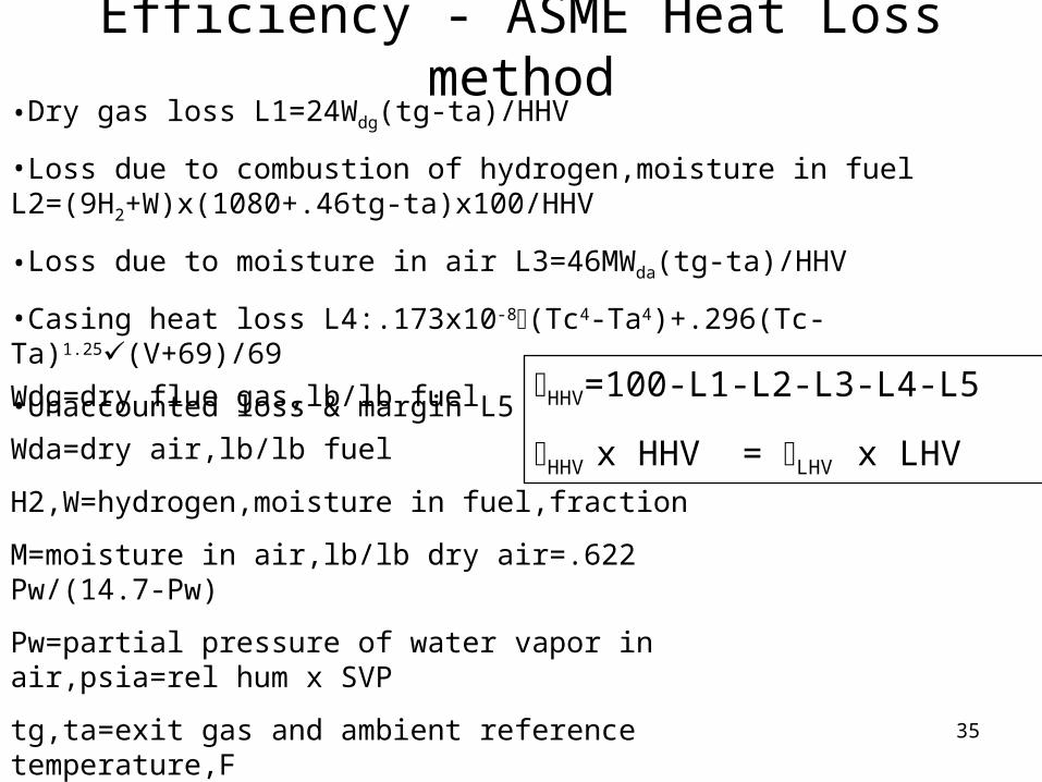
Efficiency - ASME Heat Loss method•Dry gas loss L1=24Wdg(tg-ta)/HHV
•Loss due to combustion of hydrogen,moisture in fuel L2=(9H2+W)x(1080+.46tg-ta)x100/HHV
•Loss due to moisture in air L3=46MWda(tg-ta)/HHV
•Casing heat loss L4:.173x10-8(Tc4-Ta4)+.296(Tc-Ta)1.25(V+69)/69
•Unaccounted loss & margin L5 HHV=100-L1-L2-L3-L4-L5
HHV x HHV = LHV x LHV
Wdg=dry flue gas,lb/lb fuel
Wda=dry air,lb/lb fuel
H2,W=hydrogen,moisture in fuel,fraction
M=moisture in air,lb/lb dry air=.622 Pw/(14.7-Pw)
Pw=partial pressure of water vapor in air,psia=rel hum x SVP
tg,ta=exit gas and ambient reference temperature,F
Tc,Ta=absolute casing and ambient temperatures,R
V=wind velocity,fpm: =casing emissivity

36
Furnace types
Symmetry of A and O types makes them suitable for shipping/trailer mounted units. Design of convective superheaters cumbersome in A and O.Splitting up of superheater may be warranted.

37
Boiler concept

38
Typical boiler scheme

39
Combustion ControlsSingle point positioning:Simplicity and safety.A common jackshaft is modulated by a power unit based on variations in boiler drum pressure and is mechanically linked to both the fuel control valve and air control damper.This system is limited to integral fan units only and is not for simultaneous firing of two fuels or when fuel heating value varies.
Full metering with cross-limiting:This is for accurate air/fuel ratios;keeping oxygen levels optimized and for firing precision.Fuel and air are metered continuously and adjusted as required to maintain desired air/fuel ratio. Air leads fuel on load increases and fuel leads air on load decreases. Allows simultaneous firing of two or more fuels and also when heating values vary. Expensive.Used when CO limits are strict(<50 ppm)
Parallel positioning with position feedback:This is used when pneumatic units and valves are required(hydrogen firing) but full metering is not. Position sensors on fuel and air control valves provide feedback for correct tracking and allows shutdown if not safe. Simultaneous firing of two or more fuels not allowed.
Oxygen trim added with CO control is required with single point systems

40
Soot BlowersCleaning medium may be dry saturated steam,superheated steam or compressed air.Superheated steam is effective as moisture in steam can cause erosion.Also it has greater cleaning potential on a pound basis due to the higher sonic velocity through the nozzles.This increase in sonic velocity more than offsets the loss of jet energy due to lower density. Kinetic energy of a steam jet at 200 psia is approximately twice that of air at same blowing pressure.
On larger boilers,compressed air is also used.Source may be 350-500 psig reciprocating compressors or centrifugals discharging at 150-225 psig. Steam piping must be designed for drainability,warming up,protection from freezing.Increasing of capacity of steam system is easier to accomplish as capacity limited by pressure reducing valves.Air systems demand a higher flow rate for cooling due to lower heat transfer coefficients.
Fixed blowers or non-retractable: lower gas temperatures (<1500 F)where high cleaning energy is not required.Nozzle size ranges from .25 to .375 in.
Retracts have a larger cleaning range,bigger nozzles and length vary from 3 to 50 ft.Translational speed may vary from 35 in/min to 200 in.min. Special oscillating blowers are used to clean specific areas such as furnace walls.Air medium requires a compressor while steam is available from the boiler itself. Water not recommended as blowing medium due to shock and fatigue effects.

41
Acoustic CleanersAcoustic cleaners operate on standard plant air 70-90 psi with air consumption of 60 scfm when sounding. Typically an acoustic cleaner operates for 10 secs every 10 minutes.Used in bag houses,SCR catalysts. Effective where blind spots of soot blowers cant clean.Sound energy creates fluctuations in static pressure of a flowing gas stream which causes any particles suspended in gas stream to oscillate. This action loosens deposits.
Acoustic cleaners have only 1 moving part,a titanium diaphargm. The frequent sounding of the AC keeps soot deposits from building up.The low frequency (~75 hz)high energy sound waves emitted by AC are not damaging to boiler tubes or refractory. No steam piping or steam consumption. Low installation cost. The following conditions are to be met for optimal cleaning:
1.Low moisture content-improves cleaning as build up is less.
2.Sound pressure level has to high enough throughout the vessel-140-150 db one meter from horn.
3.Cycle time between bursts should be short so particles do not adhere to each other. 10-15 secs every 10-20 min.
4.Particle removal:In vertical flow units,gravity can remove particles. In horizontal units,gas velocity should be high enough(16 ft/s) to carry away the particles without fluidizing them.
5.Sonic devices are designed for keeping a surface clean not getting it clean like a soot blower.It is important that we start with clean surfaces.
Boilers: One 250 hz ,147 db horn will clean a diameter of 10 ft

42
Furnace is the heart of the steam generator.
•Combustion must be complete-no unburnt carbon,CO
•Furnace exit gas temperature must not cause slagging problems if molten ash forms
•Heat release rates must be within limits to avoid DNB concerns.(area heat release rates more significant than volumetric for gas/oil fuels).
•Flame impingement should be avoided
•Circulation should be good
•Emissions should be met
Package boiler furnaces are typically pressurised with single FD fan operation up to about 275,000 lb/h capacity. Furnace pressure could be as high as 30-35 in wc.
Boiler Furnace

43
Furnace construction
Water cooled furnaces of membrane wall design are widely used
Partition wall is also membrane walled and helps eliminate bypassing of flue gases from furnace to convection bank,improving efficiency and lowering CO formation

44
Departure from Nucleate Boiling
When heat flux exceeds critical value,the boiling process is disrupted resulting in overheating of tubes.

45
Furnace Exit Gas Temperature
Furnace exit gas temperature is higher on gaseous fuels than on oil. Hence superheater performance will be impacted by fuel as also furnace heat absorption and heat flux.Low BTU fuels can also result in lower values.

46
Furnace RadiationFlames may be luminous and non-luminous. Radiation intensity of a luminous or semi-luminous flame is determined by presence of solid particles such as coke,ash,soot in the combustion products. For a non-luminous flame,it is the presence of triatomic gases. Gaseous substances have lower radiation intensity compared to solids.
Intensity of radiation of solid particles in a flame depends on particle size, particle concentration and properties of the solid. Coke particles are of size 10-250mm but concentration is small-0.1 kg/m3 and concentrated near the burners.Their radiation is only 25-30% of total furnace radiation. Ash particles are of same size but distributed all over the furnace volume.Their radiation is 40-60% of total furnace radiation.
In fuel oil fired boilers radiation varies along furnace length.Intense soot particles near burner have high radiation while beyond,it gets lower. Hence flame emissivity calculations involve two parts,one luminous and another non-luminous.
Ef=mEl +(1-m)Enl ,where Ef,El,Enl are emissivities of flame and luminous and non-luminous portions and m is a coefficient. For natural gas,m=0.1,while for fuel oils,it is 0.55.For solid fuels,since flame is equally bright all over the furnace,m=1.

47
Membrane wall temperatures
48
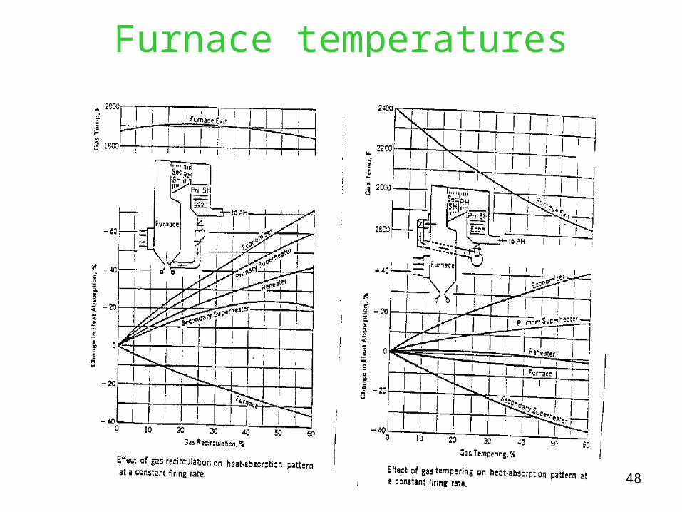
Furnace temperatures

49
MaterialsLow carbon steels(<0.15% carbon)widely used as welded pressure parts at low pressures.For structural applications and high pressure pressure parts, medium carbon steel is used(0.15-0.23% C).oxygen evolved during solidification. If no oxygen is evolved, it is killed steel. All steel used in boilers is killed steel.
Low and medium alloy steels with Cr and Mo increase oxidation resistance and strength.T91 has 9% Cr and has tendency to embrittlement but has very high strengths and used up to 1200F.
The common stainless steel alloys(18% Cr-8% Ni) are 300 series.304,321,347,316,309,310H is added for high temperature service.304H is widely used.All these require high temperature heat treatment after forming.
Ferritic stainless steels contain at least 10% Cr-has ferrite and carbide structure. As they are subject to embrittlement, they are not used as pressure parts. Used as studs for holding refractory or as shields. Difficult to weld.
Duplex alloys or bi-metallic :Load carrying alloy covered with an external layer of corrosion resistant alloy. Carbon steel clad with 304L used in paper mills. carbon steel or 0.5Cr-0.5Mo clad with alloy 825(42Ni-21.5Cr-5Mo-2.3Cu) used in refuse fired boilers.
Chromizing and alonizing used to protect tube ID surfaces from exfoliation.

50
Boiler materialsMaterial Composition Max temp,F Where used
Sa 178A(47K) C steel 950 Water wall,econ,evaporator
Sa 192(47K) C steel 950 Water wall,econ,evaporator
Sa 178C(60K) C steel 950 Water wall,econ,evaporator
Sa 210A1(60K) Csteel 950 Water wall,econ,evaporator
Sa 106B(60K) Csteel 950 Headers,pipe
Sa 210C(70K) C steel 950 Water wall,econ,evaporator
Sa516-70(70K) Csteel 800 Boiler drum
Sa 299 C steel 800 Boiler drum,headers
Sa 213-T11 1.5cr-.5 mo-si 1050 superheaters
Sa 213 T22 2.25cr-1mo 1100 Superheaters,reheaters
Sa 213-T91 9cr-1mo-v 1200 superheaters
Sa 213-TP304H 18cr-8ni 1400 Superheater,heaters
Sa 213-TP347H 18cr-10ni-cb 1400 Superheaters,reheaters
Sa213-TP310H 25cr-20ni 1500 Superheaters,reheaters
SB407-800H Ni-cr-fe 1500 Heater tubes,MSW,OTSG
SB-423-825 Ni-cr-fe-mo-cu 1000 MSW superheaters