boiler classification - saharapcc.skills4success.cosaharapcc.skills4success.co/spcc/opr/bssm/lesson...
TRANSCRIPT

B O I L E R C L A S S I F I C A T I O N
1
BOILER CLASSIFICATION
Boilers vary considerably in detail and design. Most boilers may be classified and described in terms of a few basic features or characteristics. Some knowledge of the methods of classification provides a useful basis for understanding the design and construction of the various types of naval boilers.
In the following pa rag raphs , we have considered the classification of boilers according to intended service , location of fire and water spaces, type of circulation, arrangement of steam and water spaces, number of furnaces, burner location, furnace pressure, type of super -heaters ,
control of superheat , and operating pressure .
INTENDED SERVICE A good place to begin in classifying boilers is to consider their
intended service. By this method of classif ication, boilers a re divided into two classes,
o -MAIN BOILERS . (are used to provide steam) o -AUXILIARY BOILER . (Auxiliary boilers are instal led in
many steam-driven combatant).
LOCATION OF FIRE AND WATER SPACES One of the basic classifications of boilers is according to the
relative location of the fire and water spaces. By this method of classification, boilers are divided into,
o -FIRE-TUBE BOILERS and
o -WATER-TUBE BOILERS.
o -HEAT RECOVERY STEAM GENERATOR(HRSG)
TYPE OF CIRCULATION
Water- tube boilers are further classified according to the method of water circulation. Water-tube boilers may be classified as
o -NATURAL CIRCULATION BOILERS
o -FORCED CIRCULATION BOILERS.
In natural c irculat ion boi lers , the c irculation of water depe nds
Chapter
2

B O I L E R C L A S S I F I C A T I O N
2
on the difference between the densi ty of an ascending mixture of hot water and steam and a descending body of re la t ive ly cool and steam-free water.
-The difference in densi ty occurs because the water expands as i t i s heated, and thus , becomes less dens e.
-Another way to descr ibe natura l ci rculat ion is to say that i t is caused by convect ion currents which resul t from the uneven heating of the water conta ined in the boiler .
Natural c i rculation may be e ither free or accelerated. In a boi ler with free natural c i rculat ion, the generating tubes are instal led a lmost horizonta l ly , with only a s l ight inc l ine toward the vert ica l . When the generating tubes are insta l led at a much greater angle of inc l ination, the rate of water ci rculation is defini te ly increased. Therefore, boi lers in which the tubes s lope qui te s teeply from steam drum to water drum are sa id to have natural ci rculat ion of the accelerated type.
Most boilers are des igned for accelerated natural c i rculat ion. In such boi lers , large tubes (3 inches or m ore in d iameter) are insta l led between the steam drum and the water drum. These large tubes, or DOWNCOMERS, a re located outside the furnace and away from the heat of combustion. They serve as pathways for the downward flow of relatively cool water. When enough down comers are installed, all small tubes can be generating tubes, carrying steam and water upward, and all downward flow can be carried by down comers . The size and n umb er of down comers installed varies from one type of boiler to another, but down comers are installed in all naval boilers.
o -Forced circulation boilers are, as their name implies, quite different in design from the boilers that use natural circulation. Forced circulation boilers depend upon pumps, rather than upon natural differences in density, for the circulation of water within the boiler. Because forced circulation boilers a re not l imited by the requirements that hot water and steam must be allowed to flow upward while the cooler water flows downward, a great variety of arrangements may be found in forced circulation boilers.

B O I L E R C L A S S I F I C A T I O N
3
2.1 Water-tube Boilers
Water-tube boiler
Water-tube boilers differ from shell type boilers in that the water is circulated inside the tubes, with the heat source surrounding them. Referring back to the equation for hoop stress (Equation 3.2.1), it is easy to see that because the tube diameter is significantly smaller, much higher pressures can be tolerated for the same stress.
Water-tube boilers are used in power station applications that require:
o A high steam output (up to 500 kg / s).
o High pressure steam (up to 160 bar).
o Superheated steam (up to 550°C).
However, water-tube boilers are also manufactured in sizes to compete with shell boilers. Small water-tube boilers may be manufactured and assembled into a single
B O I L E R C L A S S I F I C A T I O N
4
unit, just like packaged shell boilers, whereas large units are usually manufactured in sections for assembly on site.
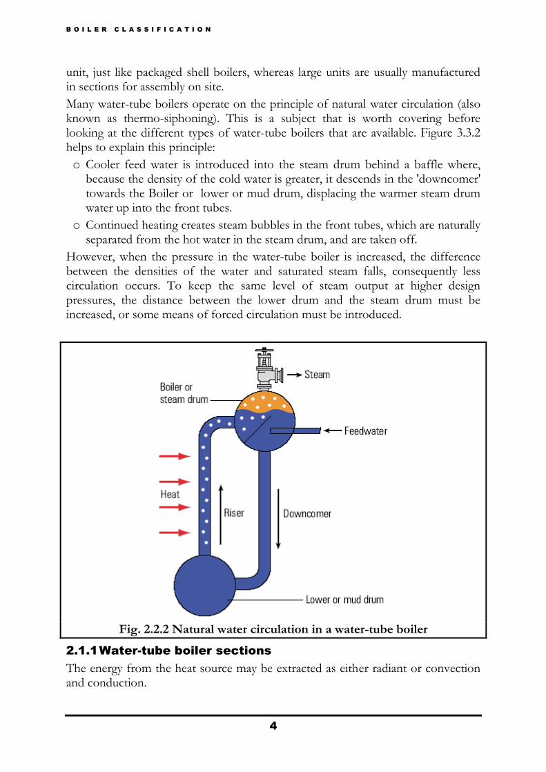
Many water-tube boilers operate on the principle of natural water circulation (also known as thermo-siphoning). This is a subject that is worth covering before looking at the different types of water-tube boilers that are available. Figure 3.3.2 helps to explain this principle:
o Cooler feed water is introduced into the steam drum behind a baffle where, because the density of the cold water is greater, it descends in the 'downcomer' towards the Boiler or lower or mud drum, displacing the warmer steam drum water up into the front tubes.
o Continued heating creates steam bubbles in the front tubes, which are naturally separated from the hot water in the steam drum, and are taken off.
However, when the pressure in the water-tube boiler is increased, the difference between the densities of the water and saturated steam falls, consequently less circulation occurs. To keep the same level of steam output at higher design pressures, the distance between the lower drum and the steam drum must be increased, or some means of forced circulation must be introduced.
Fig. 2.2.2 Natural water circulation in a water-tube boiler
2.1.1 Water-tube boiler sections
The energy from the heat source may be extracted as either radiant or convection and conduction.

B O I L E R C L A S S I F I C A T I O N
5
2.1.2 The furnace or radiant section
This is an open area accommodating the flame(s) from the burner(s). If the flames were allowed to come into contact with the boiler tubes, serious erosion and finally tube failure would occur.
The walls of the furnace section are lined with finned tubes called membrane panels, which are designed to absorb the radiant heat from the flame.
Fig. 2.2.3 Heat transfer in the furnace or radiant section
2.1.3 Convection section
This part is designed to absorb the heat from the hot gases by conduction and convection.
Large boilers may have several tube banks (also called pendants) in series, in order to gain maximum energy from the hot gases.
Fig. 2.2.4 Heat transfer in the convection section

B O I L E R C L A S S I F I C A T I O N
6
2.1.4 Water-tube boiler designation
Water- tube boilers are usually classified according to certain characteristics, see Table 3.3.1.
Table 3.3.1 Water-tube boiler classifications
2.1.5 Alternative water-tube boiler layouts
The following layouts work on the same principles as other water-tube boilers, and are available with capacities from 5 000 kg / h to 180 000 kg / h.
2.1.6 Longitudinal drum boiler
The longitudinal drum boiler was the original type of water-tube boiler that operated on the thermo-siphon principle (see Figure 2.2.5).
Cooler feed water is fed into a drum, which is placed longitudinally above the heat source. The cooler water falls down a rear circulation header into several inclined heated tubes. As the water temperature increases as it passes up through the inclined tubes, it boils and its density decreases, therefore circulating hot water and steam up the inclined tubes into the front circulation header which feeds back to the drum. In the drum, the steam bubbles separate from the water and the steam can be taken off.
Typical capacities for longitudinal drum boilers range from 2 250 kg/h to 36 000 kg/ h.
Fig. 2.2.5 longitudinal drum boiler

B O I L E R C L A S S I F I C A T I O N
7
2.1.7 Cross drum boiler
The cross drum boiler is a variant of the longitudinal drum boiler in that the drum is placed cross ways to the heat source as shown in Figure 3.3.6. The cross drum operates on the same principle as the longitudinal drum except that it achieves a more uniform temperature across the drum.
However it does risk damage due to faulty circulation at high steam loads; if the upper tubes become dry, they can overheat and eventually fail.
The cross drum boiler also has the added advantage of being able to serve a larger number of inclined tubes due to its cross ways position.
Typical capacities for a cross drum boiler range from 700 kg / h to 240 000 kg / h.
Fig. 2.2.6 Cross drum boiler
2.1.8 Bent tube or Sterling boiler
A further development of the water-tube boiler is the bent tube or Stirling boiler shown in Figure 3.3.7. Again this operates on the principle of the temperature and density of water, but utilises four drums in the following configuration.
Cooler feed water enters the left upper drum, where it falls due to greater density, towards the lower, or water drum. The water within the water drum, and the connecting pipes to the other two upper drums, are heated, and the steam bubbles produced rise into the upper drums where the steam is then taken off.
The bent tube or Stirling boiler allows for a large surface heat transfer area, as well as promoting natural water circulation.

B O I L E R C L A S S I F I C A T I O N
8
Fig. 2.2.7 Bent tube or Stirling boiler
2.1.9 Advantages of water-tube boilers:
They have a small water content, and therefore respond rapidly to load change and heat input.
The small diameter tubes and steam drum mean that much higher steam pressures can be tolerated, and up to 160 bar may be used in power stations.
The design may include many burners in any of the walls, giving horizontal, or vertical firing options, and the facility of control of temperature in various parts of the boiler. This is particularly important if the boiler has an integral superheated, and the temperature of the superheated steam needs to be controlled.
2.1.10 Disadvantages of water-tube boilers:
They are not as simple to make in the packaged form as shell boilers, which mean that more work is required on site.
The option of multiple burners may give flexibility, but the 30 or more burners used in power stations means that complex control systems are necessary.
2.1.11 Combined heat and power (CHP) plant
The water-tube boilers described above are usually of a large capacity. However, small, special purpose, smaller waste heat boilers to be used in conjunction with land based gas turbine plants are in increasing demand.
Several types of steam generating land based gas turbine plant are used:

B O I L E R C L A S S I F I C A T I O N
9
o Combined heat and power - These systems direct the hot exhaust gases from a gas turbine (approximately 500°C) through a boiler, where saturated steam is generated and used as a plant utility.
o Typical applications for these systems are on plant or sites where the demands for electricity and steam are in step and of proportions which can be matched to a CHP system. Efficiencies can reach 90%.
Gas turbine / alternator set
o Combined cycle plant - These are extensions to CHP systems, and the saturated steam is taken through a superheater to produce superheated steam. The superheater may be separately fired because of the comparatively low temperature of the gas turbine exhaust. The superheated steam produced is directed to steam turbines which drive additional alternators, and generate electricity.
The turndown ratio of these plants is poor, because of the need for the turbine to rotate at a speed synchronized to the electrical frequency. This means that it is only practical to run these plants at full-load, providing the base load of steam to the plant.
Because of the relatively low temperature of the gas turbine exhaust, compared to the burner flame in a conventional boiler, a much greater boiler heat transfer area is required for a given heat load. Also, there is no need to provide accommodation for burners. For these reasons, water-tube boilers tend to provide a better and more compact solution. Because efficiency is a major factor with CHP decision-makers, the design of these boilers may well incorporate an economiser (feed water heater).

B O I L E R C L A S S I F I C A T I O N
10
If the plant is combined cycle the design may also include a superheater. However, the
Relatively low temperatures may mean that additional burners are required to bring the steam up to the specification required for the steam turbines.
Fig. 2.2.9 A forced circulation water- tube boiler as used on CHP plant
ARRANGEMENT OF STEAM AND WATER SPACES
Natural circulation water-tube boilers are classified as DRUM-TYPE BOILERS or HEADER-TYPE BOILERS,
depending on the arrangement of the steam and water spaces. Drum-type boilers have one or more water drums (and usually one or more water headers as well). Header-type boilers have no water drum; instead, the tubes enter many headers which serve the same purpose as water drums.
What is a header, and what is the difference between a header and a drum? The term header is commonly used in engineering to describe any tube, chamber, drum, or similar piece to which tubes or pipes are connected in such a way as to permit the flow of fluid from one tube (or group of tubes) to another. Essentially, a header is a type of manifold or collection point. As far as boilers are concerned, the

B O I L E R C L A S S I F I C A T I O N
11
only distinction between a drum and a header is size. Drums maybe entered by a person while headers cannot. Both serve basically the same purpose.
Drum-type boilers are further classified according to the overall shape formed by the steam and water spaces—that is, by the tubes. For example, double-furnace boilers are often called M-type boilers because the arrangement of the tubes is roughly M-shaped. Single-furnace boilers are often called D-type boilers because the tubes form a shape that looks l ike the letter D.
NUMBER OF FURNACES
Most boilers commonly used in the plants may be classified as either SINGLE-FURNACE BOILERS or DOUBLE-FURNACE BOILERS. The D-type boiler is a single-furnace boiler; the M-type boiler is a double-furnace (divided-furnace) boiler.
BURNER LOCATION
Boilers are also classified on the basis of where their burners are located. Most burners in naval propulsion plants are located at the front of the boiler. These are called FRONT-FIRED BOILERS. Other ships, such as the AO-177 and LKA-113 class ships, have their burners on the top of the boilers. These are called TOP-FIRED BOILERS.
FURNACE PRESSURE
Another convenient boiler classification is based on the air pressure used in the furnace. Most boilers in use in plants operate with a slight air pressure (seldom over 5 psig) in the boiler furnace. This slight pressure is not enough to justify calling these boilers pressurized-furnace boilers. However, some boilers installed are truly pressurized-furnace boilers. They are called PRESSURE-FIRED or SUPERCHARGED BOILERS. These furnaces are maintained under a positive air pressure of about 65 psia (about 50 psig) when operated at full power. The air pressure in these boiler furnaces is maintained by special air compressors called superchargers.
TYPE OF SUPERHEATERS
On almost all boilers used in the plants, the super heater tubes are protected from radiant heat by water screen tubes. The water screen tubes absorb the intense radiant heat of the furnace, and the super heater tubes are heated by convection currents rather than by direct radiation. These super heaters are called CONVECTION-TYPE SUPERHEATERS.
In a few older one, the super heater tubes are not screened by water screen tubes but are exposed directly to the radiant heat of the furnace. Super heaters of this design are called RADIANT-TYPE SUPERHEATERS.
B O I L E R C L A S S I F I C A T I O N
12
CONTROL OF SUPERHEAT
A boiler that provides some means of controlling the degree of superheat independently of the rate of steam generation is said to have CONTROLLED SUPERHEAT. A boiler in which such separate control is not possible is said to have UNCONTROLLED SUPERHEAT.
Normally, the term superheat control boiler is used to identify a double-furnace boiler. The term uncontrolled superheat boiler is used to identify a single-furnace boiler.
OPERATING PRESSURE
For some purposes, it is convenient to classify boilers according to
operating pressure. Most classification of this type are approximate rather
than exact. Header-type boilers and some older drum-type boilers are often
called 400-PSI BOILERS even though their operating pressures range from
about 435 psi to 700 psi.
The term high-pressure boiler is at present used rather loosely to identify any
boiler that operates at a substantially higher pressure than the so-called 600-
PSI BOILERS. In general, we will consider any boiler that operates at 751 psi
or above as a high-pressure boiler. Many boilers operate at about 1200 psi.
These boilers are referred to as 1200-PSI BOILERS.
As you can see, classifying boilers by operating pressure is not very precise
since actual operating pressure may vary widely within any one group. Also,
any classification based on operating pressure may easily become obsolete.
What is called a high-pressure boiler today may well be called a low-pressure
boiler tomorrow.