boiler controller lambdatronic h 3200 tx - touchhoward.services/onewebmedia/tx h3200 touch... ·...
TRANSCRIPT

Operating Instructions
Boiler controller Lambdatronic H 3200 TX - TouchVersion 50.04 - Build 05.08
Translation of the original German operating instructions for technicians and operatorsRead and follow the instructions and safety information!
Technical changes, typographical errors and omissions reserved!B1020013_en | Edition 24/09/2013
Froling GesmbH | A-4710 Grieskirchen, Industriestraße 12 | www.froeling.com
Table of Contents
1 General 61.1 About these instructions 61.2 Safety information 6
2 Electrical connection and wiring 72.1 Core module and connection options 72.1.1 Board view 7 Connection instructions 82.1.2 Mains connection 92.1.3 Connecting the flue gas sensor 92.1.4 Combination with oil burner 92.1.5 Connecting the remote control 102.1.6 Boiler enable input 112.1.7 Connecting a high efficiency pump to the core module 122.2 Expansion modules 132.2.1 Heating circuit module 132.2.2 Hydraulic module 14 Connecting an isolating valve 15 Connecting a high efficiency pump to the hydraulic module 162.2.3 Wood chip module 172.2.4 Digital module 192.2.5 Power supply 202.2.6 Connecting the bus cable 202.2.7 Connect the patch cable to the bus plug 212.2.8 Setting end jumpers 212.2.9 Setting the module address 222.3 Connection diagrams according to pump types 22
3 Overview of the basic functions 243.1 Visual display 243.1.1 Status LED 243.1.2 Icons 253.2 Operating statuses 263.3 Updating the software of the touch control 273.4 Calibrating the touchscreen 29
4 Operation 314.1 Before switching on for the first time 314.1.1 Controller check 314.1.2 Check on the connected units 314.1.3 System Check 314.2 Switching the boiler on/off 324.3 Navigation within the info menu 324.4 Navigation within the system menu 334.4.1 Navigating the menus 334.5 Adjusting parameters 354.6 Setting times 36
Table of Contents
2 Froling GesmbH | A-4710 Grieskirchen, Industriestraße 12 | www.froeling.com
4.7 Setting the date/time 384.8 Quick menu 394.8.1 "Operating level” function 394.8.2 "Choose language” function 394.8.3 "Chimney sweep” function 394.8.4 "Service mode” function 394.8.5 "Extra heating” function 394.8.6 "Summer op.” function 394.8.7 “Mode in automatic mode” function 394.8.8 "Extra loading” function 394.8.9 "Touch cleaning” function 404.9 Boiler modes 404.9.1 Explanation of terms 404.9.2 Transition op. without storage tank 414.9.3 Transition op. with storage tank 424.9.4 Winter op. without storage tank 434.9.5 Winter op. with storage tank 434.9.6 Summer op. without storage tank 444.9.7 Summer op. with storage tank 454.10 Initial startup 464.10.1 Switching user level 464.10.2 Setting the system selection 47 Open the system selection menu 47 Selecting the boiler type 48 Selecting the feed system 50 System selection 50 DHW tank system 51 Heating system 52 Solar system 524.10.3 Before heating up for the first time 53 Drives 53 Checking sensors 534.10.4 Starting the system on initial startup 54 Feeding fuel into the combustion chamber 54
5 Menu overview and parameters 555.1 Menu - Heating 555.1.1 Status displays for the heating circuits 565.1.2 Temperature settings for the heating circuits 575.1.3 Heating times of the heating circuits 585.1.4 Service parameters of the heating circuits 585.1.5 Service parameters for heating up program 59 Heating up programs 605.1.6 General Settings 615.2 Menu - Water 615.2.1 Status displays for the DHW tank 625.2.2 Temperature settings of the DHW tank 625.2.3 Heating times of the DHW tank 635.2.4 Service parameters of the DHW tank 635.3 Menu - Solar 645.3.1 Status displays for the solar system 655.3.2 Temperature settings for the solar system 665.3.3 Service parameters of the solar system 675.3.4 Solar heat meter 68
Table of Contents
Operating Instructions Lambdatronic H 3200 TX - Touch | B1020013_en 3
5.4 Menu - Storage tank 695.4.1 Status displays of the storage tank 705.4.2 Temperature settings for the storage tank 705.4.3 Heating times of the storage tank 715.4.4 Service parameters of the storage tank 725.5 Menu - Boiler 735.5.1 Status displays for the boiler 745.5.2 Temperature settings for the boiler 755.5.3 Heating times of the boiler 765.5.4 Service parameters of the boiler 765.5.5 General Settings 775.6 Menu - Boiler 2 775.6.1 Status displays for the backup boiler 785.6.2 Temperature settings for the backup boiler 785.6.3 Service parameters of the backup boiler 795.7 Menu - Fuel 805.7.1 Service parameters for fuel 815.8 Menu - Network pump 815.8.1 Network pump status displays 825.8.2 Network pump temperature settings 825.8.3 Service parameters for the network pump 835.9 Menu - Cascade 845.9.1 Status displays for the cascade 855.9.2 Status display of the cascade backup boiler 855.9.3 Temperature settings for the cascade 865.9.4 Service parameters of the cascade 865.10 Menu - Difference regulator 875.10.1 Status displays for the difference regulator 885.10.2 Temperature settings for the difference regulator 885.10.3 Service parameters for the difference regulator 895.11 Menu - Circulation pump 895.11.1 Status displays for the circulation pump 905.11.2 Temperature settings for the circulation pump 905.11.3 Time settings for the circulation pump 915.11.4 Service parameters of the circulation pump 915.12 Menu - Manual 925.12.1 Manual operation 935.12.2 Digital outputs 935.12.3 Analogue outputs 945.12.4 Digital inputs 955.13 Menu - System 965.13.1 Setting 97 Adjustable parameters: Boiler temperature 97 Adjustable Parameters: Flue Gas 98 Adjustable Parameters: Air settings 99 Adjustable parameters: Fuel feed 99 Adjustable parameters: Vibrator motor/WOS/cleaning 101 Adjustable parameters: Lambda values 102 Adjustable parameters: Lambda values - LSM11 Lambda probe 102 Adjustable parameters – Lambda values – Broadband probe 103 Adjustable parameters: General settings 1055.13.2 Current values 105 Service hours 1075.13.3 Sensors and pumps 108
Table of Contents
4 Froling GesmbH | A-4710 Grieskirchen, Industriestraße 12 | www.froeling.com

5.13.4 Display allocation 1095.13.5 System selection 1105.14 Menu: Diagnostics 1105.14.1 Error display 1115.14.2 Error history 1115.14.3 Clear error history 1125.15 Menu: Display settings 1125.15.1 General 1135.15.2 Date / Time 1145.15.3 Software update / Service 1145.16 PWM / 0 - 10V settings 114
6 Troubleshooting 1166.1 Procedure for fault messages 116
7 Setting protocol 118
Table of Contents
Operating Instructions Lambdatronic H 3200 TX - Touch | B1020013_en 5
1 General
1.1 About these instructionsPlease read and follow the operating instructions, in particular the safety informationcontained therein. Keep them available next to the boiler.These operating instructions contain important information about operation, electricalconnection and troubleshooting for the Lambdatronic H 3200 TX control.
NOTICE
The values given in the parameter lists are examples, and should not be used as standard values!
The constant further development of our products means that there may be minor dif‐ferences from the pictures and content. If you discover any errors, please let us know.
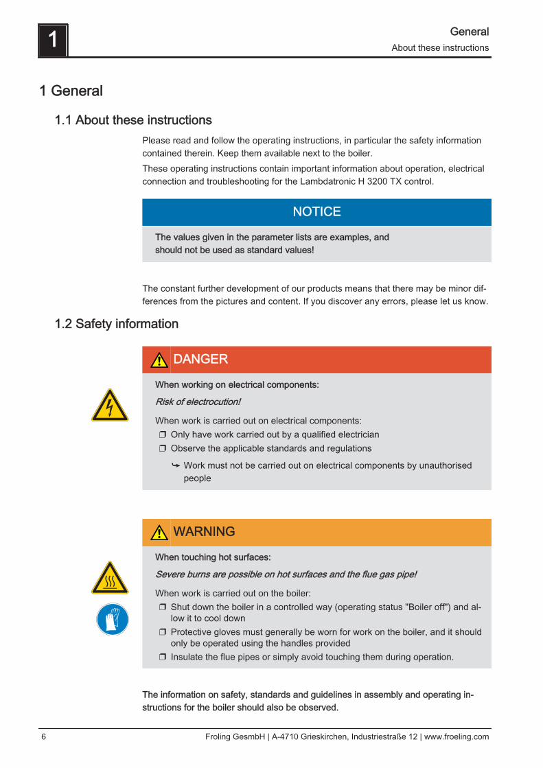
1.2 Safety information
DANGER
When working on electrical components:
Risk of electrocution!
When work is carried out on electrical components:❒ Only have work carried out by a qualified electrician❒ Observe the applicable standards and regulations
➥ Work must not be carried out on electrical components by unauthorisedpeople
WARNING
When touching hot surfaces:
Severe burns are possible on hot surfaces and the flue gas pipe!
When work is carried out on the boiler:❒ Shut down the boiler in a controlled way (operating status "Boiler off") and al‐
low it to cool down❒ Protective gloves must generally be worn for work on the boiler, and it should
only be operated using the handles provided❒ Insulate the flue pipes or simply avoid touching them during operation.
The information on safety, standards and guidelines in assembly and operating in‐structions for the boiler should also be observed.
1 GeneralAbout these instructions
6 Froling GesmbH | A-4710 Grieskirchen, Industriestraße 12 | www.froeling.com

2 Electrical connection and wiring
2.1 Core module and connection options
2.1.1 Board view
Electrical connection and wiring 2Core module and connection options
Operating Instructions Lambdatronic H 3200 TX - Touch | B1020013_en 7
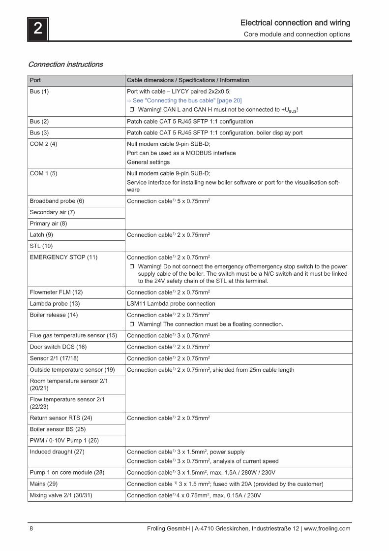
Connection instructions
Port Cable dimensions / Specifications / Information
Bus (1) Port with cable – LIYCY paired 2x2x0.5;⇨ See "Connecting the bus cable" [page 20]❒ Warning! CAN L and CAN H must not be connected to +UBUS!
Bus (2) Patch cable CAT 5 RJ45 SFTP 1:1 configuration
Bus (3) Patch cable CAT 5 RJ45 SFTP 1:1 configuration, boiler display port
COM 2 (4) Null modem cable 9-pin SUB-D;Port can be used as a MODBUS interfaceGeneral settings
COM 1 (5) Null modem cable 9-pin SUB-D;Service interface for installing new boiler software or port for the visualisation soft‐ware
Broadband probe (6) Connection cable1) 5 x 0.75mm2
Secondary air (7)
Primary air (8)
Latch (9) Connection cable1) 2 x 0.75mm2
STL (10)
EMERGENCY STOP (11) Connection cable1) 2 x 0.75mm2
❒ Warning! Do not connect the emergency off/emergency stop switch to the powersupply cable of the boiler. The switch must be a N/C switch and it must be linkedto the 24V safety chain of the STL at this terminal.
Flowmeter FLM (12) Connection cable1) 2 x 0.75mm2
Lambda probe (13) LSM11 Lambda probe connection
Boiler release (14) Connection cable1) 2 x 0.75mm2
❒ Warning! The connection must be a floating connection.
Flue gas temperature sensor (15) Connection cable1) 3 x 0.75mm2
Door switch DCS (16) Connection cable1) 2 x 0.75mm2
Sensor 2/1 (17/18) Connection cable1) 2 x 0.75mm2
Outside temperature sensor (19) Connection cable1) 2 x 0.75mm2, shielded from 25m cable length
Room temperature sensor 2/1(20/21)
Flow temperature sensor 2/1(22/23)
Return sensor RTS (24) Connection cable1) 2 x 0.75mm2
Boiler sensor BS (25)
PWM / 0-10V Pump 1 (26)
Induced draught (27) Connection cable1) 3 x 1.5mm2, power supplyConnection cable1) 3 x 0.75mm2, analysis of current speed
Pump 1 on core module (28) Connection cable1) 3 x 1.5mm2, max. 1.5A / 280W / 230V
Mains (29) Connection cable 1) 3 x 1.5 mm2; fused with 20A (provided by the customer)
Mixing valve 2/1 (30/31) Connection cable1) 4 x 0.75mm2, max. 0.15A / 230V
2 Electrical connection and wiringCore module and connection options
8 Froling GesmbH | A-4710 Grieskirchen, Industriestraße 12 | www.froeling.com
Port Cable dimensions / Specifications / Information
Heating circuit pump 2/1 (32/33) Connection cable1) 3 x 1.5mm2, max. 2.5A / 500W
Heating circuit pump HCP 0 / burn‐er relay (34)
Connection cable1) 3 x 1.5mm2, max. 3A / 600VA
(35) Connection cable1) 2 x 0.75mm2
1.YMM as per ÖVE-K41-5 or H05VV-F as per DIN VDE 0881-5
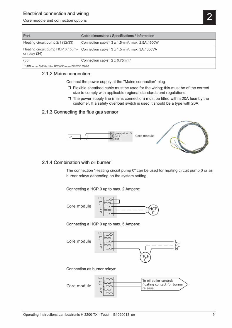
2.1.2 Mains connectionConnect the power supply at the "Mains connection" plug❒ Flexible sheathed cable must be used for the wiring; this must be of the correct
size to comply with applicable regional standards and regulations.❒ The power supply line (mains connection) must be fitted with a 20A fuse by the
customer. If a safety overload switch is used it should be a type with 20A.
2.1.3 Connecting the flue gas sensor
green-yellow
red +
blue -
Core module
2.1.4 Combination with oil burnerThe connection "Heating circuit pump 0" can be used for heating circuit pump 0 or asburner relays depending on the system setting. Connecting a HCP 0 up to max. 2 Ampere:
Core module
L1
N
HCP0
Connecting a HCP 0 up to max. 5 Ampere:
Core module
L1
N
HCP0
L
PEN
Connection as burner relays:
Core module
L1
N
To oil boiler control:
floating contact for burner
release
Electrical connection and wiring 2Core module and connection options
Operating Instructions Lambdatronic H 3200 TX - Touch | B1020013_en 9

2.1.5 Connecting the remote controlA room temperature sensor is included in the remote control, which sends the currentroom temperature to the control.
affecting room:
AUS
UHR
NACHT
TAG
FV
RFFV
COM
Raumfühler FRA
RF 1/2
Kernmodul S/P/H 3200
not affecting room:
AUS
UHR
NACHT
TAG
FV
RFFV
COM
Raumfühler FRA
RF 1/2
Kernmodul S/P/H 3200
Switch settings:
Switched-off Heating circuit deactivated, only frost protec‐tion!
Automatic mode Heating phases according to setback program
Setback mode Ignores the heating phases
Override circuit Ignores the setback
Handwheel… Allows you to adjust the temperature by +/- 3°C
IMPORTANT! See assembly instructions/functional description for room temperaturesensor FRA
2 Electrical connection and wiringCore module and connection options
10 Froling GesmbH | A-4710 Grieskirchen, Industriestraße 12 | www.froeling.com
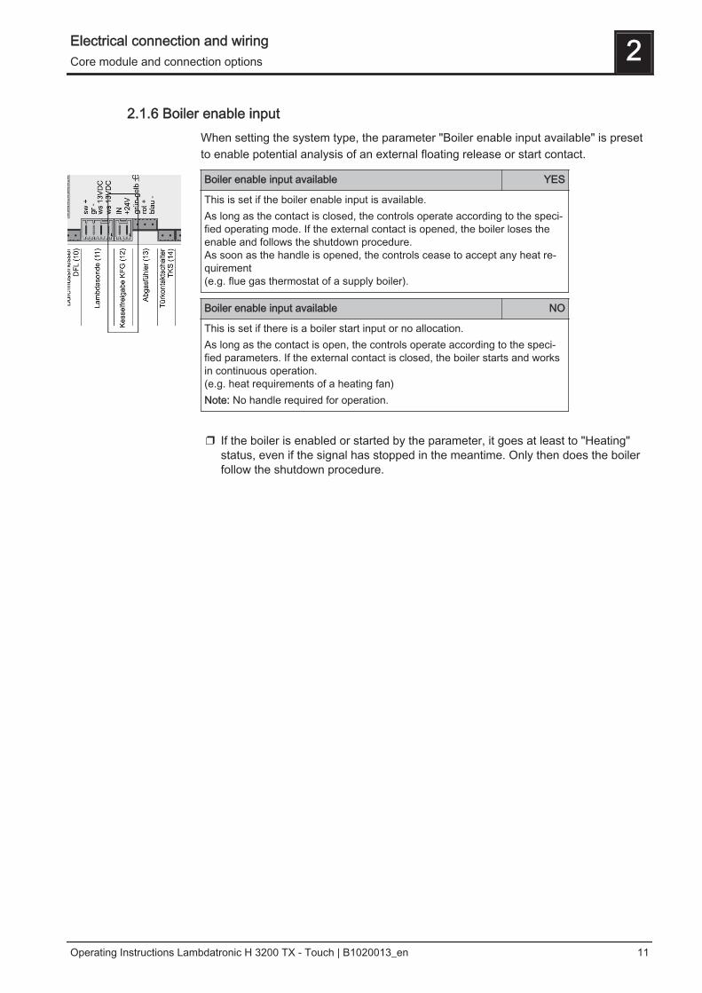
2.1.6 Boiler enable inputWhen setting the system type, the parameter "Boiler enable input available" is presetto enable potential analysis of an external floating release or start contact.
Boiler enable input available YES
This is set if the boiler enable input is available.As long as the contact is closed, the controls operate according to the speci‐fied operating mode. If the external contact is opened, the boiler loses theenable and follows the shutdown procedure. As soon as the handle is opened, the controls cease to accept any heat re‐quirement(e.g. flue gas thermostat of a supply boiler).
Boiler enable input available NO
This is set if there is a boiler start input or no allocation.As long as the contact is open, the controls operate according to the speci‐fied parameters. If the external contact is closed, the boiler starts and worksin continuous operation.(e.g. heat requirements of a heating fan)Note: No handle required for operation.
❒ If the boiler is enabled or started by the parameter, it goes at least to "Heating"
status, even if the signal has stopped in the meantime. Only then does the boilerfollow the shutdown procedure.
Electrical connection and wiring 2Core module and connection options
Operating Instructions Lambdatronic H 3200 TX - Touch | B1020013_en 11

2.1.7 Connecting a high efficiency pump to the core moduleWire the high efficiency pump as shown in the connection diagram below:
KERNMODUL
FRKEM25
PDM / 0-10V (+)PDM / 0-10V ( )
Pump 1 (L)
Pump 1 ( )
Pump 1 (N)
❒ Connect the power supply for the high efficiency pump to output "Pump 1" of thecore module
❒ Connect the PWM cable of the high efficiency pump to the corresponding port“PWM / 0-10V"➥ Make sure that the cables are configured correctly (polarity) in accordance with
the connection diagram of the pump! Important! When using a Froling pump assembly:⇨ See "Connection diagrams according to pump types" [page 22]
2 Electrical connection and wiringCore module and connection options
12 Froling GesmbH | A-4710 Grieskirchen, Industriestraße 12 | www.froeling.com
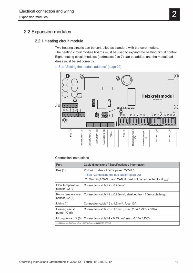
2.2 Expansion modules
2.2.1 Heating circuit moduleTwo heating circuits can be controlled as standard with the core module. The heating circuit module boards must be used to expand the heating circuit control.Eight heating circuit modules (addresses 0 to 7) can be added, and the module ad‐dress must be set correctly.⇨ See "Setting the module address" [page 22]
Connection instructions
Port Cable dimensions / Specifications / Information
Bus (1) Port with cable – LIYCY paired 2x2x0.5;⇨ See "Connecting the bus cable" [page 20]❒ Warning! CAN L and CAN H must not be connected to +UBUS!
Flow temperaturesensor 1/2 (2)
Connection cable1) 2 x 0.75mm2
Room temperaturesensor 1/2 (3)
Connection cable1) 2 x 0.75mm2, shielded from 25m cable length
Mains (4) Connection cable1) 3 x 1.5mm2, fuse 10A
Heating circuitpump 1/2 (5)
Connection cable1) 3 x 1.5mm2, max. 2.5A / 230V / 500W
Mixing valve 1/2 (6) Connection cable1) 4 x 0.75mm2, max. 0.15A / 230V1.YMM as per ÖVE-K41-5 or H05VV-F as per DIN VDE 0881-5
Electrical connection and wiring 2Expansion modules
Operating Instructions Lambdatronic H 3200 TX - Touch | B1020013_en 13
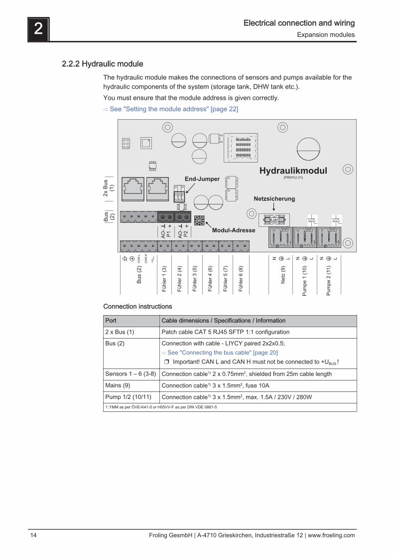
2.2.2 Hydraulic moduleThe hydraulic module makes the connections of sensors and pumps available for thehydraulic components of the system (storage tank, DHW tank etc.).You must ensure that the module address is given correctly.⇨ See "Setting the module address" [page 22]
AO
-P
1
AO
-P
2
6,3AT
Hydraulikmodul(FRHYU 21)
Bu
s (
2)
Fü
hle
r 1
(3
)
Fü
hle
r 5
(7
)
Ne
tz (
9)
Pu
mp
e 2
(11
)
Fü
hle
r 2
(4
)
Fü
hle
r 4
(6
)
Fü
hle
r 3
(5
)
Pu
mp
e 1
(1
0)
Fü
hle
r 6
(8
)
Bu
s(2
)
2x B
us
(1)
Modul-Adresse
End-Jumper
Netzsicherung
CA
N L
CA
N H
+U
Bus
N L N L N L
+ +
Connection instructions
Port Cable dimensions / Specifications / Information
2 x Bus (1) Patch cable CAT 5 RJ45 SFTP 1:1 configuration
Bus (2) Connection with cable - LIYCY paired 2x2x0.5;⇨ See "Connecting the bus cable" [page 20]❒ Important! CAN L and CAN H must not be connected to +UBUS !
Sensors 1 – 6 (3-8) Connection cable1) 2 x 0.75mm2, shielded from 25m cable length
Mains (9) Connection cable1) 3 x 1.5mm2, fuse 10A
Pump 1/2 (10/11) Connection cable1) 3 x 1.5mm2, max. 1.5A / 230V / 280W1.YMM as per ÖVE-K41-5 or H05VV-F as per DIN VDE 0881-5
2 Electrical connection and wiringExpansion modules
14 Froling GesmbH | A-4710 Grieskirchen, Industriestraße 12 | www.froeling.com
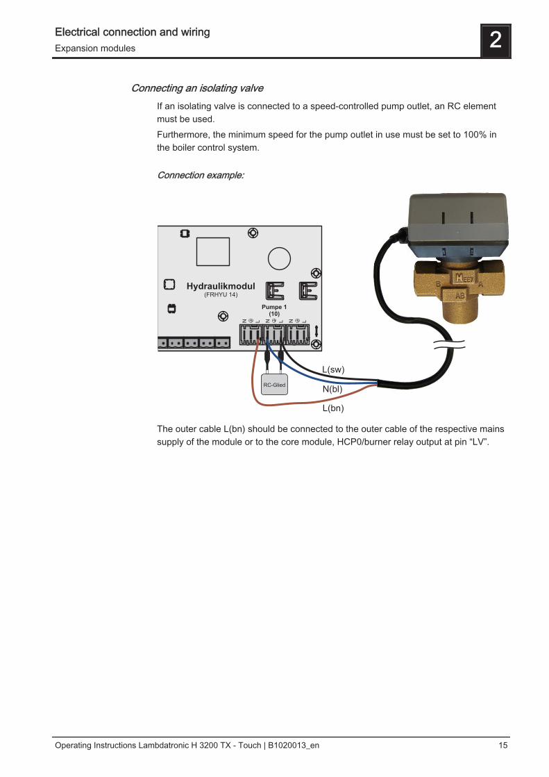
Connecting an isolating valveIf an isolating valve is connected to a speed-controlled pump outlet, an RC elementmust be used.Furthermore, the minimum speed for the pump outlet in use must be set to 100% inthe boiler control system.
Connection example:
The outer cable L(bn) should be connected to the outer cable of the respective mainssupply of the module or to the core module, HCP0/burner relay output at pin “LV”.
Electrical connection and wiring 2Expansion modules
Operating Instructions Lambdatronic H 3200 TX - Touch | B1020013_en 15
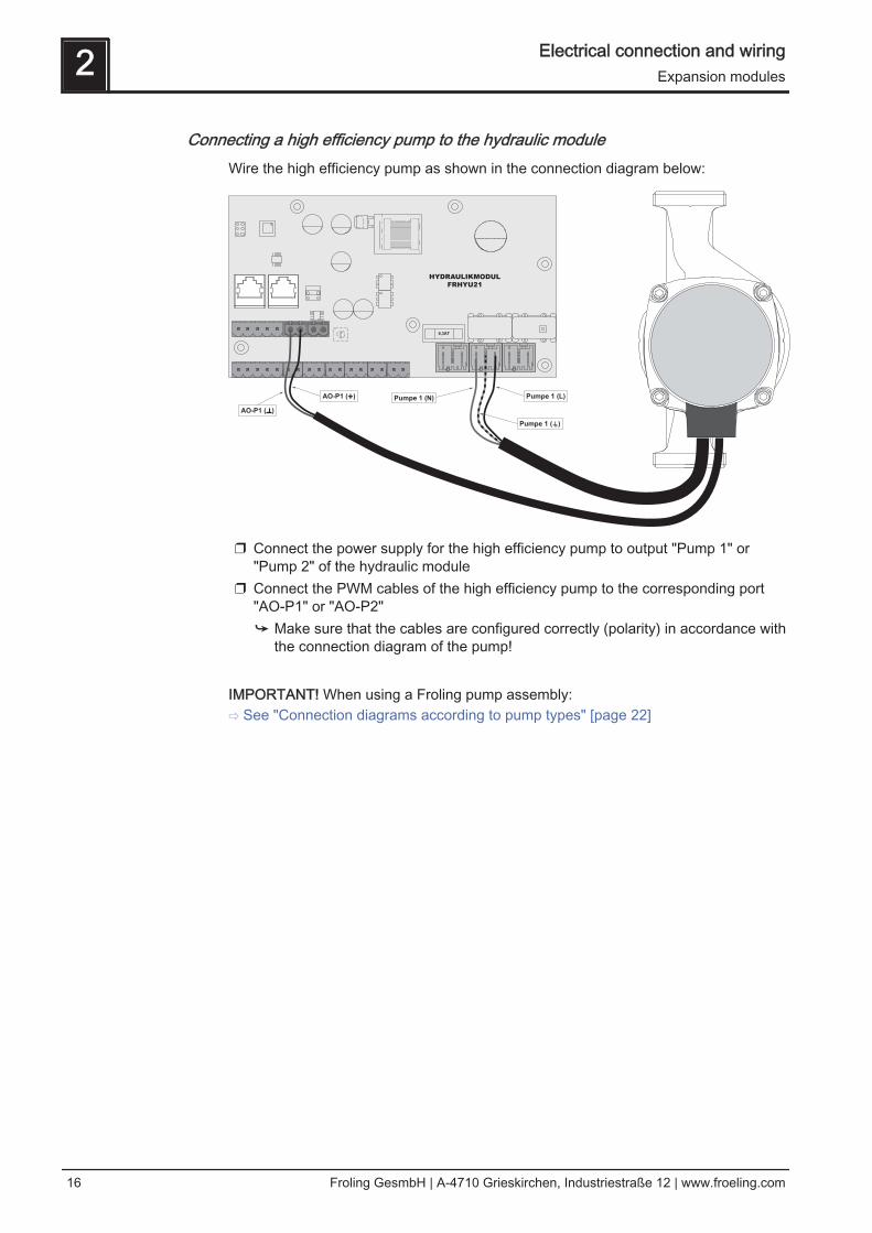
Connecting a high efficiency pump to the hydraulic moduleWire the high efficiency pump as shown in the connection diagram below:
❒ Connect the power supply for the high efficiency pump to output "Pump 1" or"Pump 2" of the hydraulic module
❒ Connect the PWM cables of the high efficiency pump to the corresponding port"AO-P1" or "AO-P2"➥ Make sure that the cables are configured correctly (polarity) in accordance with
the connection diagram of the pump! IMPORTANT! When using a Froling pump assembly:⇨ See "Connection diagrams according to pump types" [page 22]
2 Electrical connection and wiringExpansion modules
16 Froling GesmbH | A-4710 Grieskirchen, Industriestraße 12 | www.froeling.com
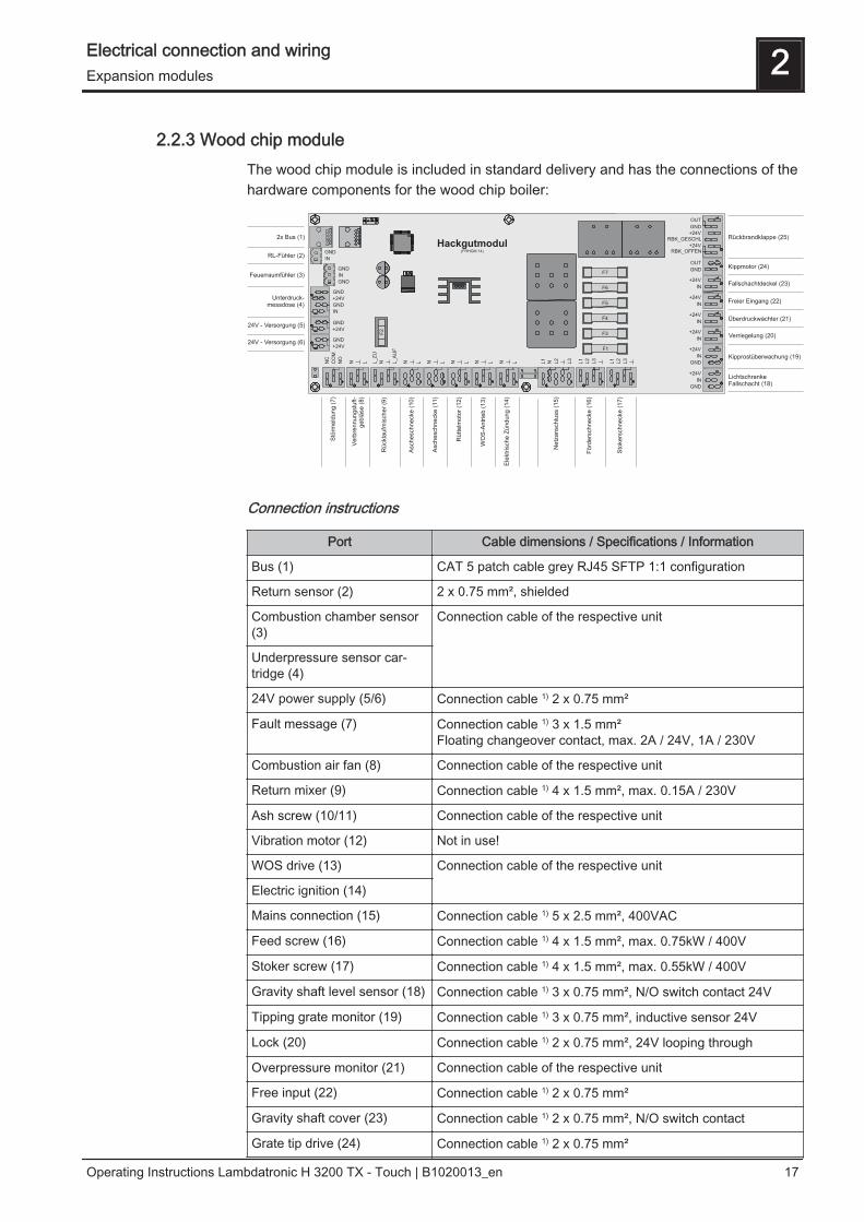
2.2.3 Wood chip moduleThe wood chip module is included in standard delivery and has the connections of thehardware components for the wood chip boiler:
Connection instructions
Port Cable dimensions / Specifications / Information
Bus (1) CAT 5 patch cable grey RJ45 SFTP 1:1 configuration
Return sensor (2) 2 x 0.75 mm², shielded
Combustion chamber sensor(3)
Connection cable of the respective unit
Underpressure sensor car‐tridge (4)
24V power supply (5/6) Connection cable 1) 2 x 0.75 mm²
Fault message (7) Connection cable 1) 3 x 1.5 mm²Floating changeover contact, max. 2A / 24V, 1A / 230V
Combustion air fan (8) Connection cable of the respective unit
Return mixer (9) Connection cable 1) 4 x 1.5 mm², max. 0.15A / 230V
Ash screw (10/11) Connection cable of the respective unit
Vibration motor (12) Not in use!
WOS drive (13) Connection cable of the respective unit Electric ignition (14)
Mains connection (15) Connection cable 1) 5 x 2.5 mm², 400VAC
Feed screw (16) Connection cable 1) 4 x 1.5 mm², max. 0.75kW / 400V
Stoker screw (17) Connection cable 1) 4 x 1.5 mm², max. 0.55kW / 400V
Gravity shaft level sensor (18) Connection cable 1) 3 x 0.75 mm², N/O switch contact 24V
Tipping grate monitor (19) Connection cable 1) 3 x 0.75 mm², inductive sensor 24V
Lock (20) Connection cable 1) 2 x 0.75 mm², 24V looping through
Overpressure monitor (21) Connection cable of the respective unit
Free input (22) Connection cable 1) 2 x 0.75 mm²
Gravity shaft cover (23) Connection cable 1) 2 x 0.75 mm², N/O switch contact
Grate tip drive (24) Connection cable 1) 2 x 0.75 mm²
Electrical connection and wiring 2Expansion modules
Operating Instructions Lambdatronic H 3200 TX - Touch | B1020013_en 17
Port Cable dimensions / Specifications / Information
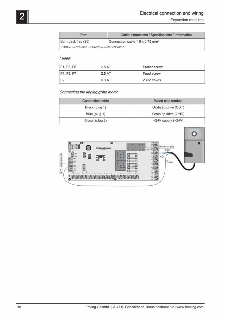
Burn back flap (25) Connection cable 1) 6 x 0.75 mm²1.YMM as per ÖVE-K41-5 or H05VV-F as per DIN VDE 0881-5
Fuses:
F1, F3, F6 2.5 AT Stoker screw
F4, F5, F7 2.5 AT Feed screw
F2 6.3 AT 230V drives
Connecting the tipping grate motor
Connection cable Wood chip module
Black (plug 1) Grate tip drive (OUT)
Blue (plug 1) Grate tip drive (GND)
Brown (plug 2) +24V supply (+24V)
2 Electrical connection and wiringExpansion modules
18 Froling GesmbH | A-4710 Grieskirchen, Industriestraße 12 | www.froeling.com
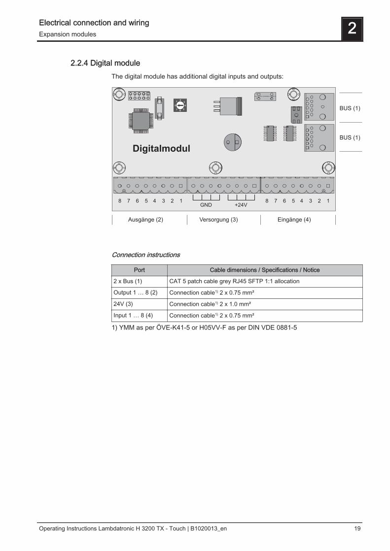
2.2.4 Digital moduleThe digital module has additional digital inputs and outputs:
Connection instructions
Port Cable dimensions / Specifications / Notice
2 x Bus (1) CAT 5 patch cable grey RJ45 SFTP 1:1 allocation
Output 1 … 8 (2) Connection cable1) 2 x 0.75 mm²
24V (3) Connection cable1) 2 x 1.0 mm²
Input 1 … 8 (4) Connection cable1) 2 x 0.75 mm²
1) YMM as per ÖVE-K41-5 or H05VV-F as per DIN VDE 0881-5
Electrical connection and wiring 2Expansion modules
Operating Instructions Lambdatronic H 3200 TX - Touch | B1020013_en 19

2.2.5 Power supplyThe power supply is used to supply all parts of the system that consume energy with24 VDC:
Connection instructions
Connection Cable dimensions / Specifications / Notice
Mains Connection cable 1) 3 x 1.5 mm²
24V power supply Connection cable 1) 2 x 1.0 mm², max. 2A
1) YMM as per ÖVE-K41-5 or H05VV-F as per DIN VDE 0881-5
Fuses
F1 2 AT 24 VDC
2.2.6 Connecting the bus cableFor the bus connections between the individual modules, cable type LIYCY paired 2x2x0.5 should be used. The connection to the 5-pin plugs should becarried out according to the following diagram:
+UBUS
CAN H
CAN L
+UBUS
CAN H
CAN L
Braided shield
White
Green
Yellow
Brown
Braided shield
White
Green
Yellow
Brown
2 Electrical connection and wiringExpansion modules
20 Froling GesmbH | A-4710 Grieskirchen, Industriestraße 12 | www.froeling.com
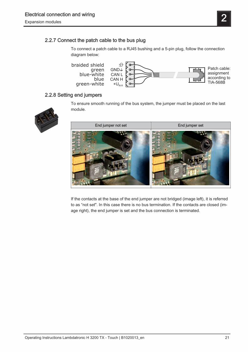
2.2.7 Connect the patch cable to the bus plugTo connect a patch cable to a RJ45 bushing and a 5-pin plug, follow the connectiondiagram below:
2.2.8 Setting end jumpersTo ensure smooth running of the bus system, the jumper must be placed on the lastmodule.
End jumper not set End jumper set
If the contacts at the base of the end jumper are not bridged (image left), it is referredto as “not set". In this case there is no bus termination. If the contacts are closed (im‐age right), the end jumper is set and the bus connection is terminated.
Electrical connection and wiring 2Expansion modules
Operating Instructions Lambdatronic H 3200 TX - Touch | B1020013_en 21

2.2.9 Setting the module addressFor hydraulic modules or heating circuit modules it is necessary to set the required or‐der with the module addresses. The first board of a module type should always havethe address 0, so that the standard hydraulic systems set do not have to be subse‐quently configured. For further module types ascending module addresses (address 1- 7) are set.A hydraulic module with address 0 is included in standard delivery. If a second hy‐draulic module is also installed, address 1 is set.
Module address set
Heating circuit mod‐ule
Hydraulic module
Heating circuit Sensor Pump
0 03 – 04 0.1 – 0.6 0.1 – 0.2
1 05 – 06 1.1 – 1.6 1.1 – 1.2
2 07 – 08 2.1 – 2.6 2.1 – 2.2
3 09 – 10 3.1 – 3.6 3.1 – 3.2
4 11 – 12 4.1 – 4.6 4.1 – 4.2
5 13 – 14 5.1 – 5.6 5.1 – 5.2
6 15 – 16 6.1 – 6.6 6.1 – 6.2
7 17 - 18 7.1 – 7.7 7.1 – 7.2
2 Electrical connection and wiringExpansion modules
22 Froling GesmbH | A-4710 Grieskirchen, Industriestraße 12 | www.froeling.com
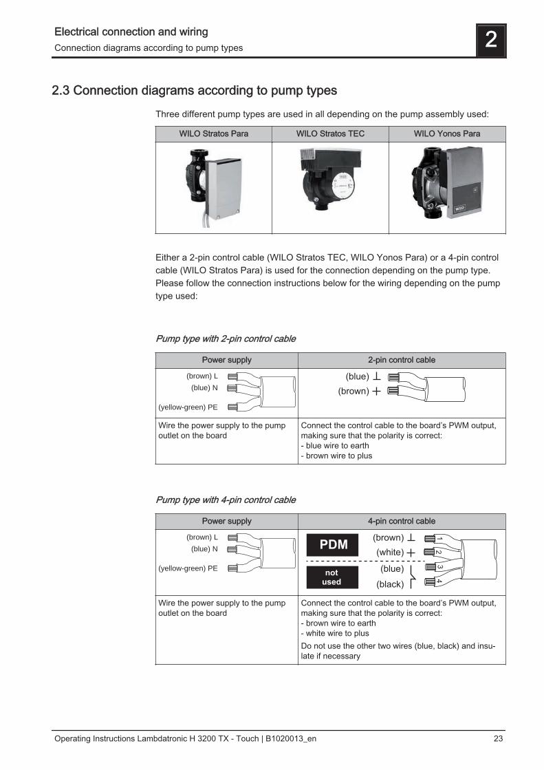
2.3 Connection diagrams according to pump types
Three different pump types are used in all depending on the pump assembly used:
WILO Stratos Para WILO Stratos TEC WILO Yonos Para
Either a 2-pin control cable (WILO Stratos TEC, WILO Yonos Para) or a 4-pin controlcable (WILO Stratos Para) is used for the connection depending on the pump type.Please follow the connection instructions below for the wiring depending on the pumptype used:
Pump type with 2-pin control cable
Power supply 2-pin control cable
(brown) L
(blue) N
(yellow-green) PE
Wire the power supply to the pumpoutlet on the board
Connect the control cable to the board’s PWM output,making sure that the polarity is correct:- blue wire to earth- brown wire to plus
Pump type with 4-pin control cable
Power supply 4-pin control cable
(brown) L
(blue) N
(yellow-green) PE
Wire the power supply to the pumpoutlet on the board
Connect the control cable to the board’s PWM output,making sure that the polarity is correct:- brown wire to earth- white wire to plusDo not use the other two wires (blue, black) and insu‐late if necessary
Electrical connection and wiring 2Connection diagrams according to pump types
Operating Instructions Lambdatronic H 3200 TX - Touch | B1020013_en 23
3 Overview of the basic functions
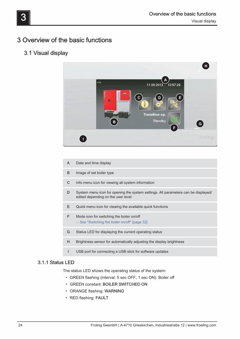
3.1 Visual display
G
H
A
C D E
F
B
I
A Date and time display
B Image of set boiler type
C Info menu icon for viewing all system information
D System menu icon for opening the system settings. All parameters can be displayed/edited depending on the user level
E Quick menu icon for viewing the available quick functions
F Mode icon for switching the boiler on/off⇨ See "Switching the boiler on/off" [page 32]
G Status LED for displaying the current operating status
H Brightness sensor for automatically adjusting the display brightness
I USB port for connecting a USB stick for software updates
3.1.1 Status LEDThe status LED shows the operating status of the system:▪ GREEN flashing (interval: 5 sec OFF, 1 sec ON): Boiler off▪ GREEN constant: BOILER SWITCHED ON▪ ORANGE flashing: WARNING▪ RED flashing: FAULT
3 Overview of the basic functionsVisual display
24 Froling GesmbH | A-4710 Grieskirchen, Industriestraße 12 | www.froeling.com
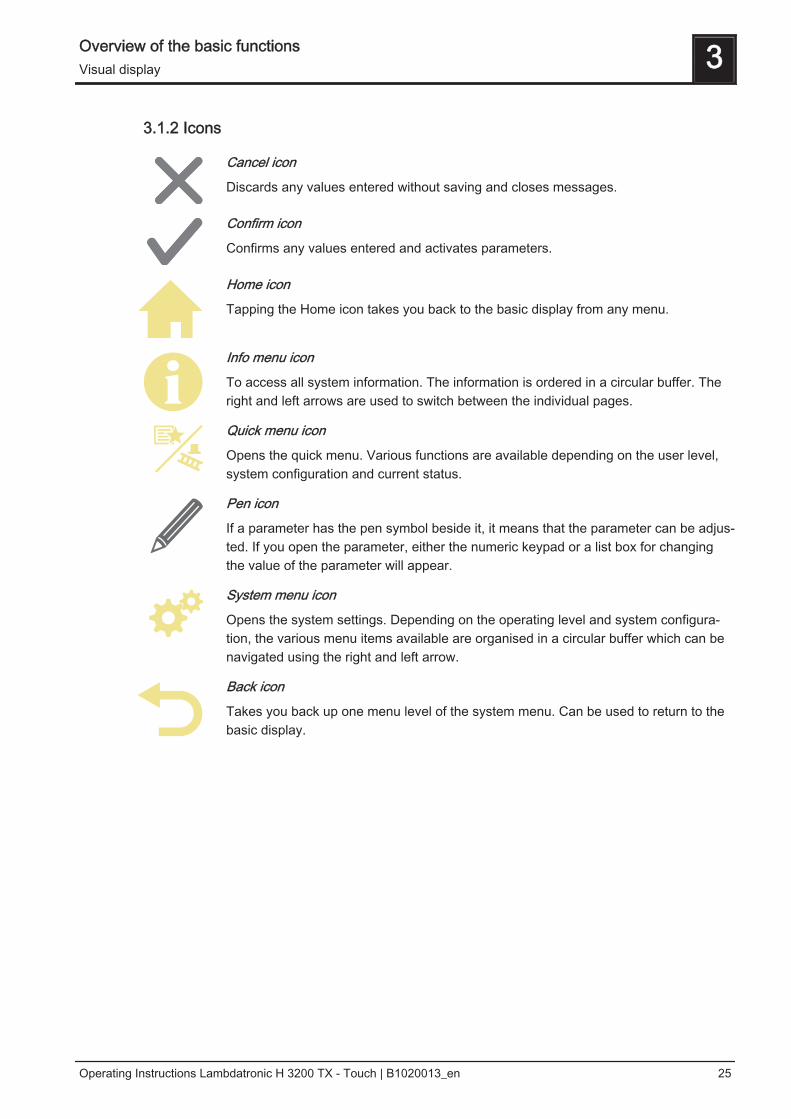
3.1.2 Icons
Cancel icon
Discards any values entered without saving and closes messages.
Confirm icon
Confirms any values entered and activates parameters.
Home icon
Tapping the Home icon takes you back to the basic display from any menu.
Info menu icon
To access all system information. The information is ordered in a circular buffer. Theright and left arrows are used to switch between the individual pages.
Quick menu icon
Opens the quick menu. Various functions are available depending on the user level,system configuration and current status.
Pen icon
If a parameter has the pen symbol beside it, it means that the parameter can be adjus‐ted. If you open the parameter, either the numeric keypad or a list box for changingthe value of the parameter will appear.
System menu icon
Opens the system settings. Depending on the operating level and system configura‐tion, the various menu items available are organised in a circular buffer which can benavigated using the right and left arrow.
Back icon
Takes you back up one menu level of the system menu. Can be used to return to thebasic display.
Overview of the basic functions 3Visual display
Operating Instructions Lambdatronic H 3200 TX - Touch | B1020013_en 25
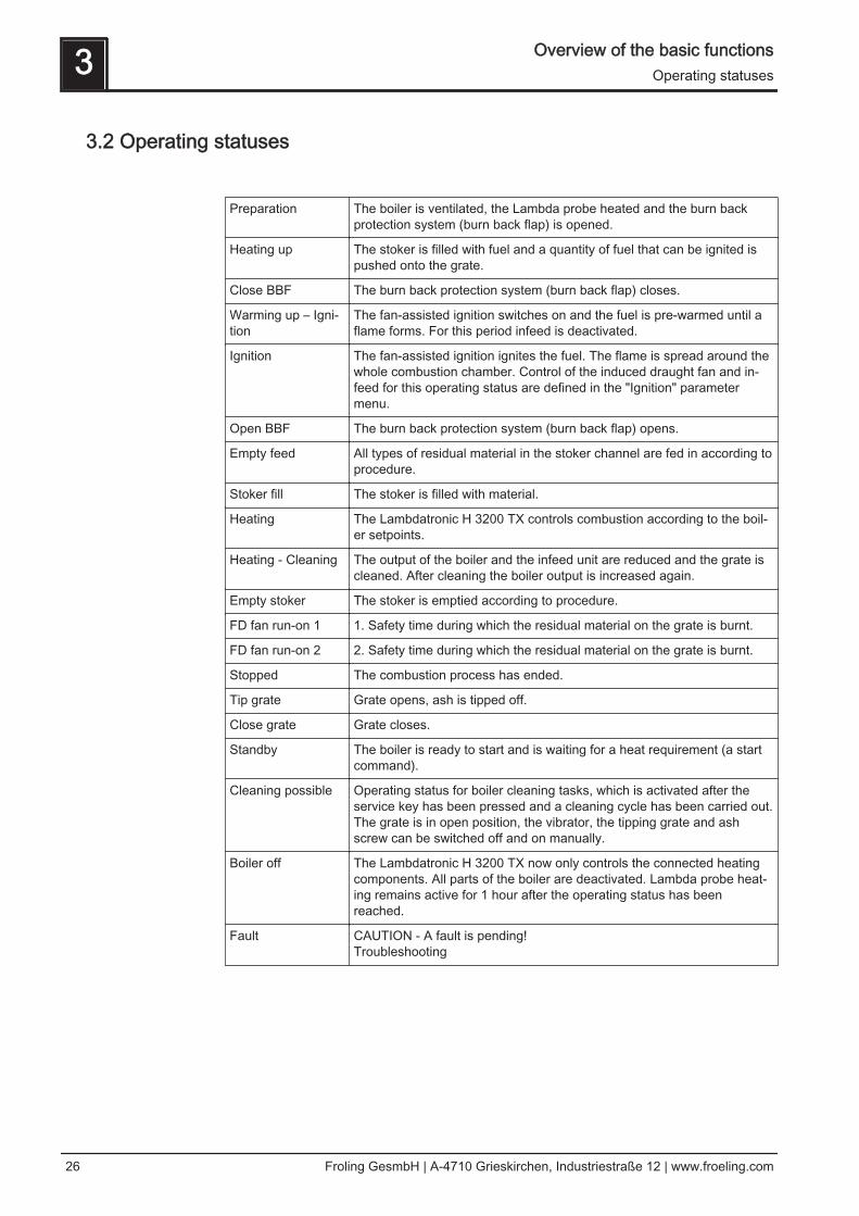
3.2 Operating statuses
Preparation The boiler is ventilated, the Lambda probe heated and the burn backprotection system (burn back flap) is opened.
Heating up The stoker is filled with fuel and a quantity of fuel that can be ignited ispushed onto the grate.
Close BBF The burn back protection system (burn back flap) closes.
Warming up – Igni‐tion
The fan-assisted ignition switches on and the fuel is pre-warmed until aflame forms. For this period infeed is deactivated.
Ignition The fan-assisted ignition ignites the fuel. The flame is spread around thewhole combustion chamber. Control of the induced draught fan and in‐feed for this operating status are defined in the "Ignition" parametermenu.
Open BBF The burn back protection system (burn back flap) opens.
Empty feed All types of residual material in the stoker channel are fed in according toprocedure.
Stoker fill The stoker is filled with material.
Heating The Lambdatronic H 3200 TX controls combustion according to the boil‐er setpoints.
Heating - Cleaning The output of the boiler and the infeed unit are reduced and the grate iscleaned. After cleaning the boiler output is increased again.
Empty stoker The stoker is emptied according to procedure.
FD fan run-on 1 1. Safety time during which the residual material on the grate is burnt.
FD fan run-on 2 2. Safety time during which the residual material on the grate is burnt.
Stopped The combustion process has ended.
Tip grate Grate opens, ash is tipped off.
Close grate Grate closes.
Standby The boiler is ready to start and is waiting for a heat requirement (a startcommand).
Cleaning possible Operating status for boiler cleaning tasks, which is activated after theservice key has been pressed and a cleaning cycle has been carried out.The grate is in open position, the vibrator, the tipping grate and ashscrew can be switched off and on manually.
Boiler off The Lambdatronic H 3200 TX now only controls the connected heatingcomponents. All parts of the boiler are deactivated. Lambda probe heat‐ing remains active for 1 hour after the operating status has beenreached.
Fault CAUTION - A fault is pending!Troubleshooting
3 Overview of the basic functionsOperating statuses
26 Froling GesmbH | A-4710 Grieskirchen, Industriestraße 12 | www.froeling.com

3.3 Updating the software of the touch control❒ Insert the USB stick with the necessary data (linux.bin; rootfs.img; update) into the
USB port❒ “Display settings” menu → “Software update / Service”❒ Set “Restart control / Update” parameter to “Yes”
➥ Update will begin
Display during the update:
Overview of the basic functions 3Updating the software of the touch control
Operating Instructions Lambdatronic H 3200 TX - Touch | B1020013_en 27
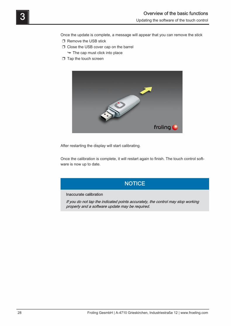
Once the update is complete, a message will appear that you can remove the stick❒ Remove the USB stick❒ Close the USB cover cap on the barrel
➥ The cap must click into place❒ Tap the touch screen
After restarting the display will start calibrating. Once the calibration is complete, it will restart again to finish. The touch control soft‐ware is now up to date.
NOTICE
Inaccurate calibration
If you do not tap the indicated points accurately, the control may stop workingproperly and a software update may be required.
3 Overview of the basic functionsUpdating the software of the touch control
28 Froling GesmbH | A-4710 Grieskirchen, Industriestraße 12 | www.froeling.com

3.4 Calibrating the touchscreenIf the touchscreen stops working properly, it will need to be calibrated.❒ Go to the “Display settings” menu❒ Scroll down with the down arrow until the “Software update / Service" submenu
appears and open the submenu
❒ In the “Software update / Service" menu open the “Recalibrate touch con-
trol” parameter
Overview of the basic functions 3Calibrating the touchscreen
Operating Instructions Lambdatronic H 3200 TX - Touch | B1020013_en 29

❒ Set the parameter to “YES” and confirm at the bottom right➥ The touchscreen will restart and begin calibrating
To calibrate the touchscreen, you much press five points indicated by a crosshair inthe order shown. The control will restart after calibration.
NOTICE
Inaccurate calibration
If you do not tap the indicated points accurately, the control may stop workingproperly and a software update may be required.
3 Overview of the basic functionsCalibrating the touchscreen
30 Froling GesmbH | A-4710 Grieskirchen, Industriestraße 12 | www.froeling.com

4 Operation
4.1 Before switching on for the first time
NOTICE
You should have the initial startup carried out by the authorised heating engineerfrom Froling customer services.
4.1.1 Controller check❒ Check boards for foreign bodies (pieces of wire, washers, screws ...)❒ Carry out a wiring check:
Check for loose, uninsulated wires, which could cause a short-circuit❒ Check plug configuration of pumps, mixing valves and other units, which have
NOT been prepared by Froling❒ Check the connection of the BUS cable for short-circuits❒ Check the specified addresses and terminal jumpers on the individual modules
(heating circuit modules, hydraulic modules, displays etc.)⇨ See "Setting the module address" [page 22] and⇨ See "Setting end jumpers" [page 21]
4.1.2 Check on the connected units❒ Check that all units that are used are connected correctly❒ Carry out a wiring check:
Check for loose or uninsulated wires in the terminal boxes of the pumps, mixer and switch valve, which could cause a short-circuit
4.1.3 System Check❒ Check that the main fuse for the boiler has a sufficient rated amperage (20A )
➥ If a safety overload switch is used, it should be a type with 20A.
Operation 4Before switching on for the first time
Operating Instructions Lambdatronic H 3200 TX - Touch | B1020013_en 31
4.2 Switching the boiler on/off Boiler is switched on. Heating circuits and domestic hot water are controlled accordingto the programs and times set. The control follows the boiler shutdown procedure and starts the cleaning cycle. Afterthe cleaning cycle the boiler switches to "Boiler off" status. The Lambdatronic H 3200TX controls the connected heating components. All parts of the boiler are deactivated.Chamber discharge system active!
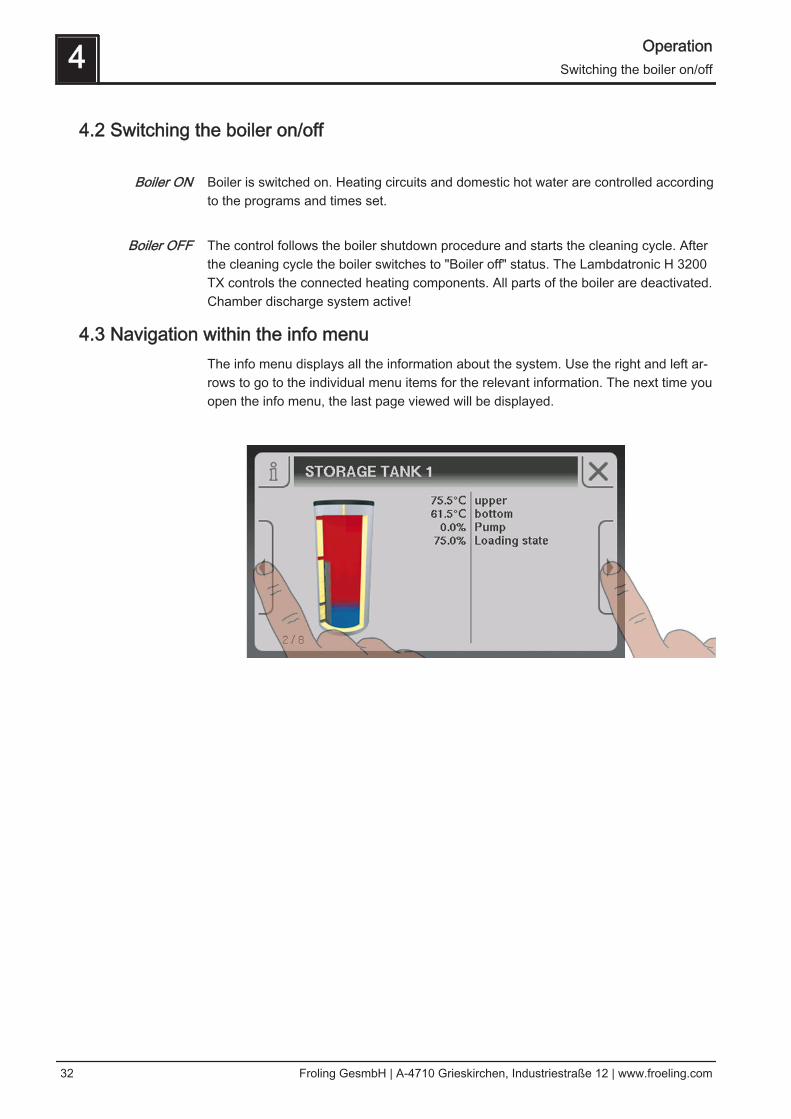
4.3 Navigation within the info menuThe info menu displays all the information about the system. Use the right and left ar‐rows to go to the individual menu items for the relevant information. The next time youopen the info menu, the last page viewed will be displayed.
Boiler ON
Boiler OFF
4 OperationSwitching the boiler on/off
32 Froling GesmbH | A-4710 Grieskirchen, Industriestraße 12 | www.froeling.com

4.4 Navigation within the system menuThe system menu shows the menu items available depending on the user level andthe system configuration. Tap the icon to open the corresponding menu item. The sys‐tem menu is structured in a circular buffer, which can be navigated using the right andleft arrows. The next time you open the system menu, the last page viewed will be dis‐played.
4.4.1 Navigating the menusAfter you open a menu item, the corresponding status display with current values willappear. If, for example, several heating circuits are installed, you can use the right andleft arrows to navigate to the desired heating circuit. You can open any other menuitems available in the same way.
The individual menus are divided into tabs for quicker navigation.❒ Tap on the desired tab
➥ The list of parameters for the selected area will appear
Operation 4Navigation within the system menu
Operating Instructions Lambdatronic H 3200 TX - Touch | B1020013_en 33

The parameter list shows three parameters. The up and down arrows can be used toscroll through longer lists of parameters. If you have reached the start or end of theparameter list, the relevant arrow symbol will become inactive.
4 OperationNavigation within the system menu
34 Froling GesmbH | A-4710 Grieskirchen, Industriestraße 12 | www.froeling.com
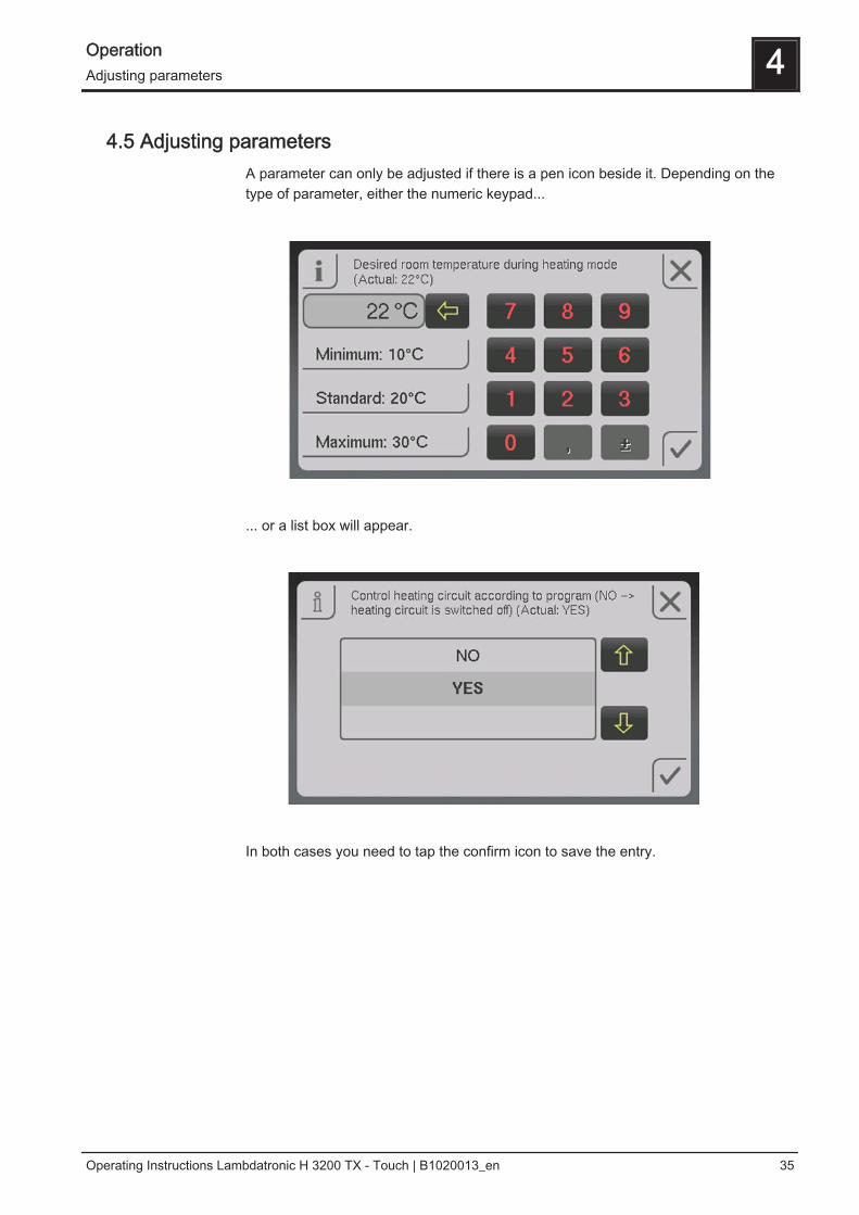
4.5 Adjusting parametersA parameter can only be adjusted if there is a pen icon beside it. Depending on thetype of parameter, either the numeric keypad...
... or a list box will appear.
In both cases you need to tap the confirm icon to save the entry.
Operation 4Adjusting parameters
Operating Instructions Lambdatronic H 3200 TX - Touch | B1020013_en 35
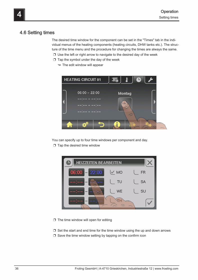
4.6 Setting timesThe desired time window for the component can be set in the "Times" tab in the indi‐vidual menus of the heating components (heating circuits, DHW tanks etc.). The struc‐ture of the time menu and the procedure for changing the times are always the same.❒ Use the left or right arrow to navigate to the desired day of the week❒ Tap the symbol under the day of the week
➥ The edit window will appear
You can specify up to four time windows per component and day.❒ Tap the desired time window
❒ The time window will open for editing
❒ Set the start and end time for the time window using the up and down arrows❒ Save the time window setting by tapping on the confirm icon
4 OperationSetting times
36 Froling GesmbH | A-4710 Grieskirchen, Industriestraße 12 | www.froeling.com

To delete a time window, set the times so that the hour and minute displays are re‐placed by two dashes.
If you want to apply the time window setting to another day in addition, you can do thisby activating the relevant day.
Operation 4Setting times
Operating Instructions Lambdatronic H 3200 TX - Touch | B1020013_en 37

4.7 Setting the date/time❒ To set / adjust the date and time displayed, tap on the date/time at the top right of
the basic display.
❒ A menu will then appear allowing you to adjust the date and time. To apply the
new values you need to confirm the date and time by tapping the “confirm” icon.
4 OperationSetting the date/time
38 Froling GesmbH | A-4710 Grieskirchen, Industriestraße 12 | www.froeling.com

4.8 Quick menu
4.8.1 "Operating level” functionTo change the operating level you need to enter the relevant code.⇨ See "Switching user level" [page 46]
4.8.2 "Choose language” functionThe control starts in German by default. If you change the language of the control, itwill restart, uploading all text in the selected language from the core module.
4.8.3 "Chimney sweep” functionThe chimney sweep function is used for measuring boiler emissions using the chim‐ney sweeper. For further information and procedure for measuring emissions, see theoperating instructions of the boiler.❒ The boiler runs for 45 minutes at nominal load
➥ The boiler temperature setpoint is set to 85 °C➥ The heating pumps switch on and the mixer valves regulate to the maximum
flow temperature setpoint➥ DHW tank and storage tank loading pump are controlled as normal
4.8.4 "Service mode” functionOnly possible in "Boiler off" operating status.The boiler switches to "Cleaning" status and starts the cleaning cycle. When this is fin‐ished the boiler switches to "Boiler off" status.
4.8.5 "Extra heating” functionDuring extra heating, heating and domestic hot water are heated for 6 hours. Themode setting is ignored.Caution: The external temperature heating limit set in the "Heating" menu is active andcan prevent release of the heating circuits.
4.8.6 "Summer op.” functionTo change to summer mode. Domestic hot water loading is controlled according to theprogram that is set, the heating circuit controller is deactivated.
4.8.7 “Mode in automatic mode” function⇨ See "Boiler modes" [page 40]
4.8.8 "Extra loading” functionOne-off manual loading of domestic hot water. After loading, the mode that was previ‐ously set becomes active again.
Operation 4Quick menu
Operating Instructions Lambdatronic H 3200 TX - Touch | B1020013_en 39
4.8.9 "Touch cleaning” functionFor cleaning the touchscreen surface. The screen is disabled for 10 seconds to allowyou to clean it without opening a menu or inadvertently adjusting a parameter.
4.9 Boiler modes
4.9.1 Explanation of termsBoiler timeThe time in which the boiler is producing heat, i.e. during this time the boiler is adjus‐ted to its boiler temperature setpoint. Outside this time there is no heat available forthe heating system.❒ If there is a storage tank, the boiler time is replaced by the storage time
Heating times of the boiler Storage tank loading timeThe time in which the storage tank can be loaded by the boiler, provided that the crite‐rion for starting the boiler is met ("Boiler start if difference betweenboiler setpoint and top store is larger“ parameter).❒ Storage tank loading only takes place within the defined time window.
⇨ See "Heating times of the storage tank" [page 71] Heating timeThe time in which the heating circuit is supplied at the desired temperature. Outsidethis time (setback mode) the heating circuit is supplied at reduced temperature.❒ Requirement: a sufficiently high temperature in the boiler or top storage tank.
⇨ See "Heating times of the heating circuits" [page 58] DHW tank loading timeThe time in which DHW tank loading is released.❒ Requirement: The DHW tank temperature is below the minimum value and the
boiler or storage tank temperature is sufficiently high.⇨ See "Heating times of the DHW tank" [page 63]
4 OperationQuick menu
40 Froling GesmbH | A-4710 Grieskirchen, Industriestraße 12 | www.froeling.com
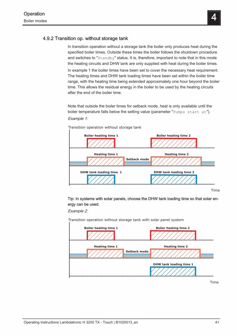
4.9.2 Transition op. without storage tankIn transition operation without a storage tank the boiler only produces heat during thespecified boiler times. Outside these times the boiler follows the shutdown procedureand switches to "Standby" status. It is, therefore, important to note that in this modethe heating circuits and DHW tank are only supplied with heat during the boiler times.In example 1 the boiler times have been set to cover the necessary heat requirement.The heating times and DHW tank loading times have been set within the boiler timerange, with the heating time being extended approximately one hour beyond the boilertime. This allows the residual energy in the boiler to be used by the heating circuitsafter the end of the boiler time. Note that outside the boiler times for setback mode, heat is only available until theboiler temperature falls below the setting value (parameter "Pumps start at").Example 1:
Boiler heating time 1
Heating time 1 Heating time 2
DHW tank loading time 1 DHW tank loading time 2
Setback mode
Boiler heating time 2
Transition operation without storage tank
Time
Tip: In systems with solar panels, choose the DHW tank loading time so that solar en‐ergy can be used.Example 2:
Boiler heating time 1
Heating time 1 Heating time 2
DHW tank loading time 1
Setback mode
Boiler heating time 2
Transition operation without storage tank with solar panel system
Time
Operation 4Boiler modes
Operating Instructions Lambdatronic H 3200 TX - Touch | B1020013_en 41

4.9.3 Transition op. with storage tankIn transition operation with storage tank the boiler only produces heat if the storagetank actually requests heat within the specified storage tank loading time. Outsidethese times the boiler is in “Standby" status.The heating times should be set within the storage tank loading times so that the pro‐vision of heat is guaranteed over the entire heating time.Note that the heating circuit and DHW tank are only supplied with heat if the storagetank temperature is sufficient for the requirement.Example 1:
Heating time 1 Heating time 2
DHW tank loading time 1
Setback mode
Storage tank loading time 1
DHW tank loading time 2
Transition operation with storage tank
Time
Tip. In systems with a storage tank and solar panels, choose the storage tank loadingtime so that solar energy can be used.In order to ensure that there is sufficient heat at the start of the DHW tank loading timeand heating time, we recommend setting the storage tank charging time to begin be‐fore the start of the DHW tank time or heating time.Example 2:
Heating time 1 Heating time 2
DHW tank loading time 1
Setback mode
Storage tank loading time 1
DHW tank loading time 2
Transition operation with storage tank and solar panel system
Time
4 OperationBoiler modes
42 Froling GesmbH | A-4710 Grieskirchen, Industriestraße 12 | www.froeling.com
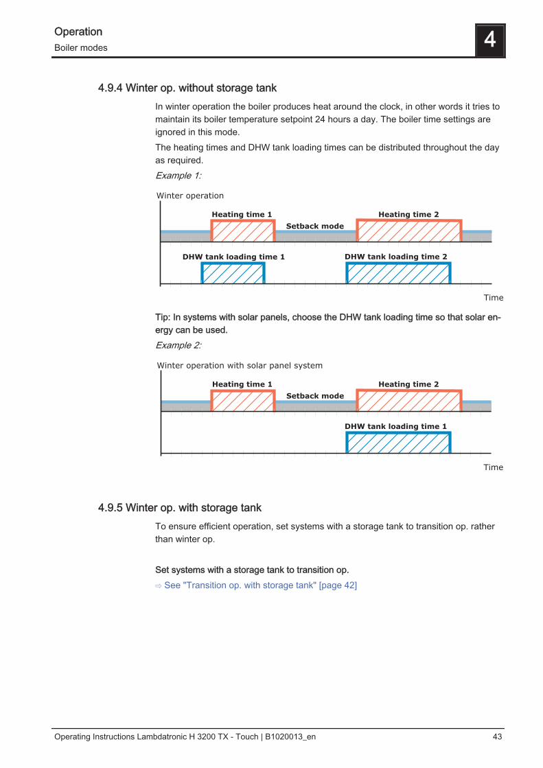
4.9.4 Winter op. without storage tankIn winter operation the boiler produces heat around the clock, in other words it tries tomaintain its boiler temperature setpoint 24 hours a day. The boiler time settings areignored in this mode.The heating times and DHW tank loading times can be distributed throughout the dayas required.Example 1:
Heating time 1 Heating time 2
DHW tank loading time 1
Setback mode
DHW tank loading time 2
Winter operation
Time
Tip: In systems with solar panels, choose the DHW tank loading time so that solar en‐ergy can be used.Example 2:
Heating time 1 Heating time 2
Setback mode
DHW tank loading time 1
Winter operation with solar panel system
Time
4.9.5 Winter op. with storage tankTo ensure efficient operation, set systems with a storage tank to transition op. ratherthan winter op. Set systems with a storage tank to transition op.⇨ See "Transition op. with storage tank" [page 42]
Operation 4Boiler modes
Operating Instructions Lambdatronic H 3200 TX - Touch | B1020013_en 43
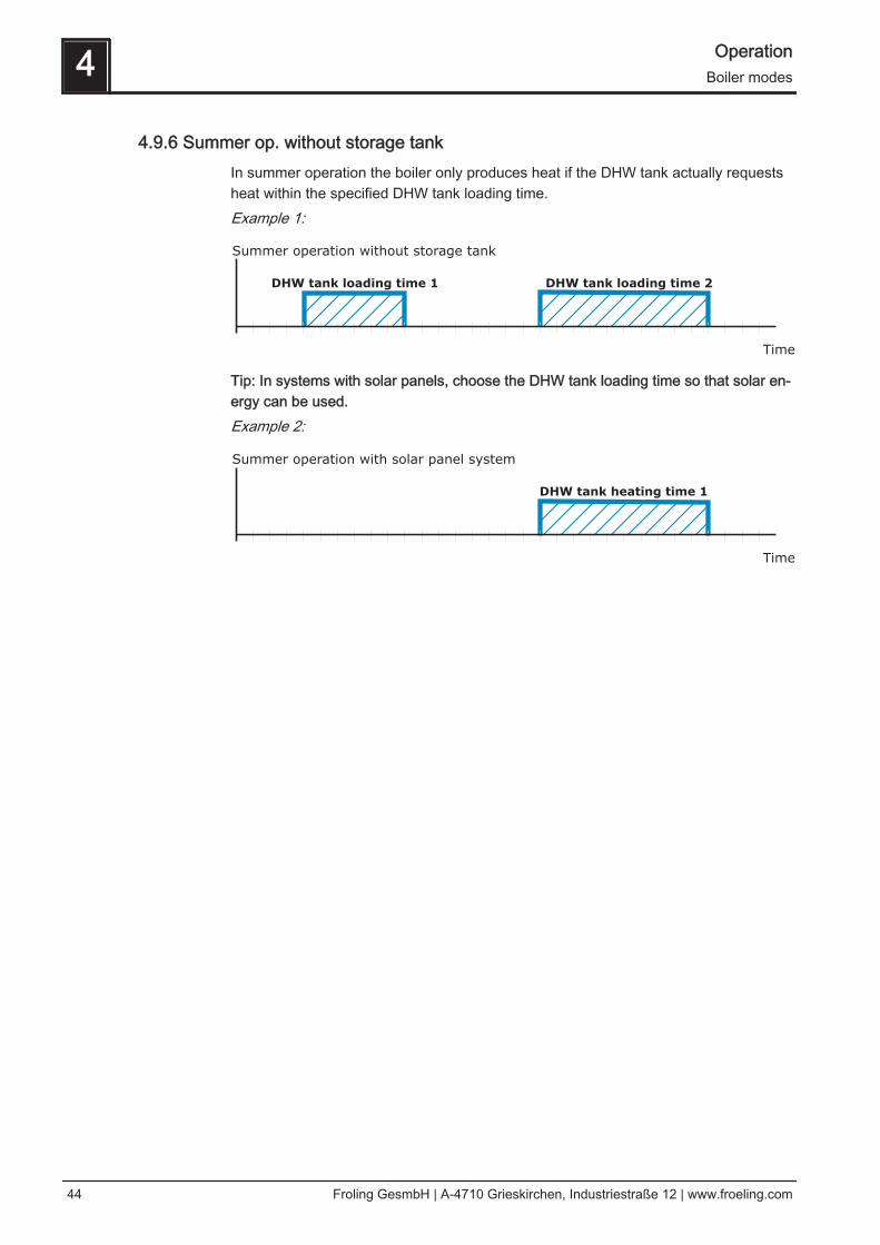
4.9.6 Summer op. without storage tankIn summer operation the boiler only produces heat if the DHW tank actually requestsheat within the specified DHW tank loading time.Example 1:
DHW tank loading time 1 DHW tank loading time 2
Summer operation without storage tank
Time
Tip: In systems with solar panels, choose the DHW tank loading time so that solar en‐ergy can be used.Example 2:
DHW tank heating time 1
Summer operation with solar panel system
Time
4 OperationBoiler modes
44 Froling GesmbH | A-4710 Grieskirchen, Industriestraße 12 | www.froeling.com
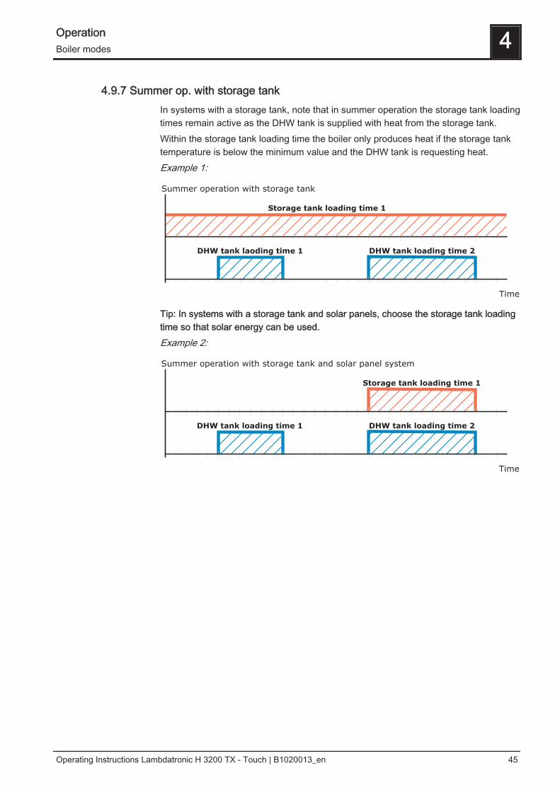
4.9.7 Summer op. with storage tankIn systems with a storage tank, note that in summer operation the storage tank loadingtimes remain active as the DHW tank is supplied with heat from the storage tank.Within the storage tank loading time the boiler only produces heat if the storage tanktemperature is below the minimum value and the DHW tank is requesting heat.Example 1:
Storage tank loading time 1
DHW tank laoding time 1 DHW tank loading time 2
Summer operation with storage tank
Time
Tip: In systems with a storage tank and solar panels, choose the storage tank loadingtime so that solar energy can be used.Example 2:
Storage tank loading time 1
DHW tank loading time 1 DHW tank loading time 2
Summer operation with storage tank and solar panel system
Time
Operation 4Boiler modes
Operating Instructions Lambdatronic H 3200 TX - Touch | B1020013_en 45
4.10 Initial startup
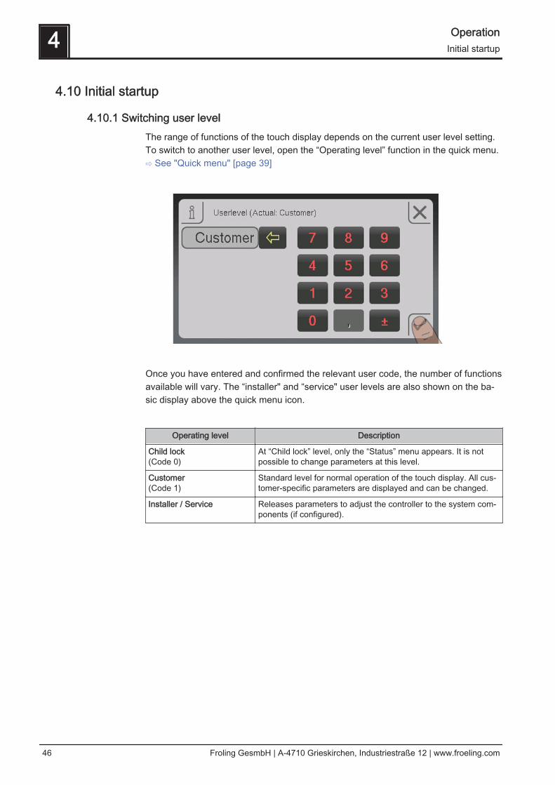
4.10.1 Switching user levelThe range of functions of the touch display depends on the current user level setting.To switch to another user level, open the “Operating level” function in the quick menu. ⇨ See "Quick menu" [page 39]
Once you have entered and confirmed the relevant user code, the number of functionsavailable will vary. The “installer" and “service" user levels are also shown on the ba‐sic display above the quick menu icon.
Operating level Description
Child lock(Code 0)
At “Child lock” level, only the “Status” menu appears. It is notpossible to change parameters at this level.
Customer(Code 1)
Standard level for normal operation of the touch display. All cus‐tomer-specific parameters are displayed and can be changed.
Installer / Service Releases parameters to adjust the controller to the system com‐ponents (if configured).
4 OperationInitial startup
46 Froling GesmbH | A-4710 Grieskirchen, Industriestraße 12 | www.froeling.com
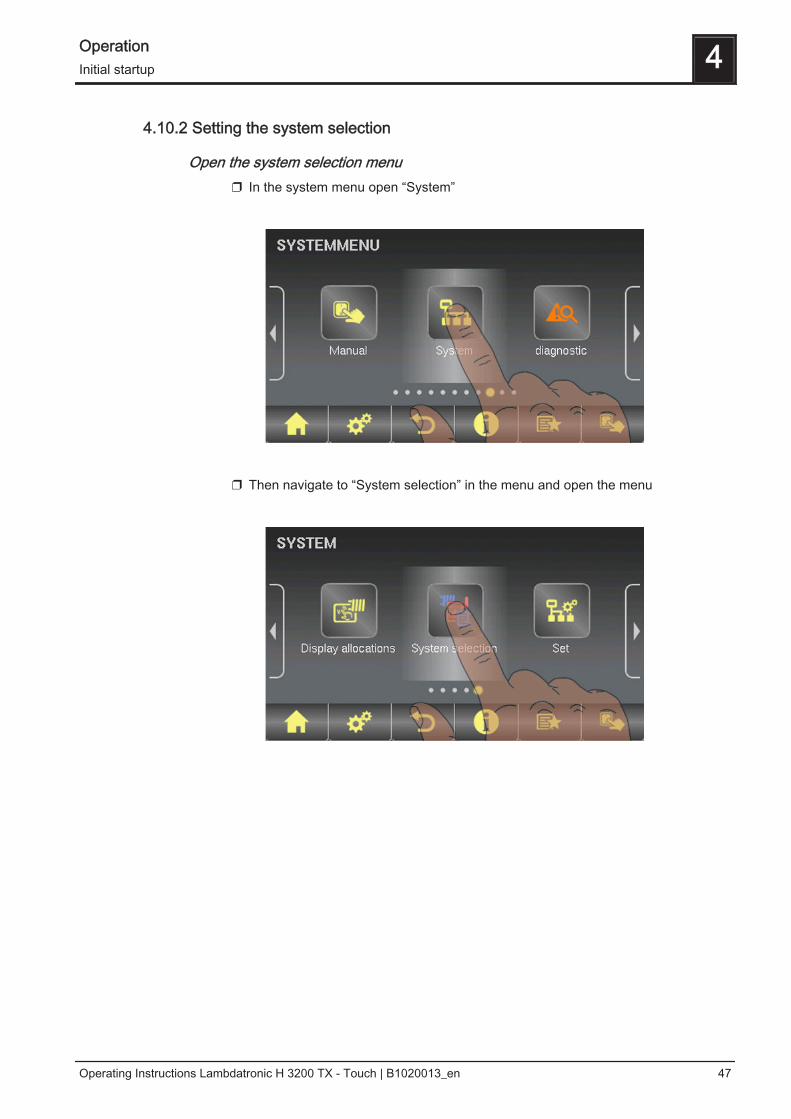
4.10.2 Setting the system selection
Open the system selection menu❒ In the system menu open “System”
❒ Then navigate to “System selection” in the menu and open the menu
Operation 4Initial startup
Operating Instructions Lambdatronic H 3200 TX - Touch | B1020013_en 47

Selecting the boiler typeThe boiler type selection of the TX wood chip boiler is divided into two output bands:TX 150TX 200 – 250❒ In the Boiler type menu open the relevant menu
❒ In the submenu set the boiler output and the fuel used, and activate the relevant
parameters.➥ Active parameters are identifiable by the confirm icon
NOTICE! The boiler and specified material values must be applied before you exit thismenu!
Adopt specified boiler values NO
Adopt specified material values NO
Boiler enable input available NO
Boiler stops automatically when no heat required NO
Combustion chamber overpressure sensor installed YES
Combustion chamber temperature sensor installed YES
Underpressure transmitter installed YES
FGR installed NO
4 OperationInitial startup
48 Froling GesmbH | A-4710 Grieskirchen, Industriestraße 12 | www.froeling.com
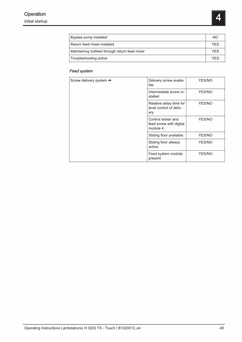
Bypass pump installed NO
Return feed mixer installed YES
Maintaining outfeed through return feed mixer YES
Troubleshooting active YES
Feed system
Screw delivery system ➔ Delivery screw availa‐ble
YES/NO
Intermediate screw in‐stalled
YES/NO
Relative delay time forlevel control of deliv‐ery
YES/NO
Control stoker andfeed screw with digitalmodule 4
YES/NO
Sliding floor available YES/NO
Sliding floor alwaysactive
YES/NO
Feed system modulepresent
YES/NO
Operation 4Initial startup
Operating Instructions Lambdatronic H 3200 TX - Touch | B1020013_en 49

Selecting the feed system
System selection
Hydraulic system 0Hydraulic system 1Hydraulic system 2Hydraulic system 3Hydraulic system 4
SELECTFor description see “ Lambdatronic H 3200 TXEnergy Systems” brochure
Hydraulic system for S3 boiler DO NOT SELECT
Hydraulic system 12Hydraulic system 13
SELECTFor description see “ Lambdatronic H 3200 TXEnergy Systems” brochure
Variant 1Variants 2 and 5Variant 3Variant 4
Multiple house diagrams
Slave boiler for boiler sequence control Only for systems in the cascade!
If the system has a Non-binding Planning Suggestion, the hydraulic system settingcan be found at the top right-hand corner of the planning suggestion.
4 OperationInitial startup
50 Froling GesmbH | A-4710 Grieskirchen, Industriestraße 12 | www.froeling.com

Otherwise, the selection table below shows the hydraulic system to be set for the spe‐cific system:
DHW tank system
DHW tank 01 installed ❒
DHW tank 02 installed ❒
: :
DHW tank 08 installed ❒
Operation 4Initial startup
Operating Instructions Lambdatronic H 3200 TX - Touch | B1020013_en 51

Heating system
Heating circuit 01 installed ❒
Remote control 01 installed ❒
Heating circuit 02 installed ❒
Remote control 02 installed ❒
: :
Heating circuit 18 installed ❒
Remote control 18 installed ❒
❒ The “remote control XX installed” parameter should be checked if any of the thethree remote controls shown is used for the respective heating circuit.
Solar system
Solar collector 01 installed ❒
A second pump is used instead of the isolating valve ❒
4 OperationInitial startup
52 Froling GesmbH | A-4710 Grieskirchen, Industriestraße 12 | www.froeling.com

4.10.3 Before heating up for the first time❒ Check the system pressure of the heating system❒ Check that the heating system is fully ventilated❒ Check that the safety devices are present and working correctly❒ Check that there is sufficient ventilation in the boiler room❒ Check the seal of the boiler
➥ All doors and inspection openings must be tightly sealed! ❒ Calibrate the broadband probe
⇨ See "Starting calibration" [page 104] ❒ Check that the Door switch is working correctly
⇨ See "Digital inputs" [page 95]
Drives❒ Check that drives and actuators are working and turning in the right direction
⇨ See "Analogue outputs" [page 94] and ⇨ See "Digital outputs" [page 93]
Checking sensorsCheck the sensors shown below in the digital input menu:⇨ See "Digital inputs" [page 95]
Sensor Assignment Description
Door contact A0 … Door closed, switch activatedA1 … Door open, switch not activated
Set the switch so that the in‐duced draught fan operateswhen the insulating door isopen.
Grate sensor A0 … Grate openA1 … Grate closed
Flue gas tempera‐ture monitor(overpressure sen‐sor)
A0 … Overpressure detected, sensor coveredA1 … No overpressure, sensor not covered
Gravity shaft cover A0 … Cover open, switch not activatedA1 … Cover closed, switch activated
Burn back flap A0 … Burn back flap openA1 … Burn back flap closed
The two parameters must al‐ways be different.
Operation 4Initial startup
Operating Instructions Lambdatronic H 3200 TX - Touch | B1020013_en 53
4.10.4 Starting the system on initial startup
Feeding fuel into the combustion chamberFor initial startup there is no fuel in the stoker and in the feed screw.❒ Set the "Delivery system from bunker" parameter in the Manual operation
menu to ON.Open the gravity shaft cover briefly at regular intervals and check for fuel:❒ As soon as the first pieces of fuel fall through the burn back flap / rotary valve, set
the "Delivery system from bunker" parameter back to OFF.❒ Close the gravity shaft cover and start the system in automatic mode.
Observe and note the following times (current and maximum) during the first heatingup procedure: ▪ Time until fuel falls onto the grate: ……… seconds▪ Time until a sufficient quantity for ignition is present on the grate: ………. seconds
❒ Note the actual times and make appropriate adjustments to the parameter, "The
time until the stoker is full is", in the "Adjustable parameters - Fuelslide-in" menu or the parameter, "Feed time until there is a fuelquantity suitable for ignition", in the "Adjustable parameters - Ignition"menu.
4 OperationInitial startup
54 Froling GesmbH | A-4710 Grieskirchen, Industriestraße 12 | www.froeling.com
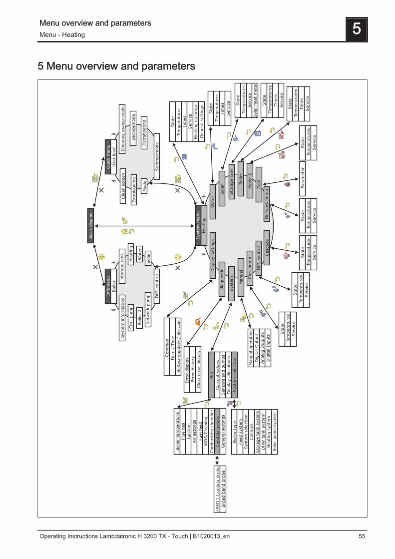
5 Menu overview and parameters
Menu overview and parameters 5Menu - Heating
Operating Instructions Lambdatronic H 3200 TX - Touch | B1020013_en 55
5.1 Menu - Heating
⇨ See "Navigation within the system menu" [page 33]
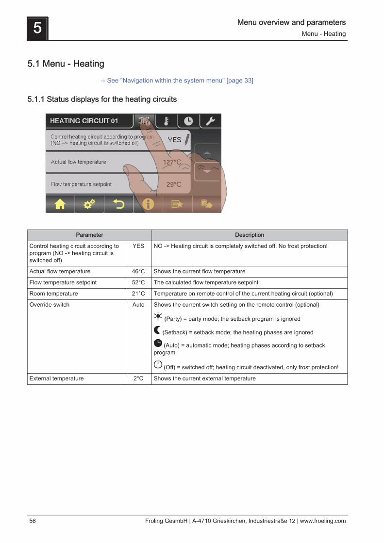
5.1.1 Status displays for the heating circuits
Parameter Description
Control heating circuit according toprogram (NO -> heating circuit isswitched off)
YES NO -> Heating circuit is completely switched off. No frost protection!
Actual flow temperature 46°C Shows the current flow temperature
Flow temperature setpoint 52°C The calculated flow temperature setpoint
Room temperature 21°C Temperature on remote control of the current heating circuit (optional)
Override switch Auto Shows the current switch setting on the remote control (optional)
(Party) = party mode; the setback program is ignored
(Setback) = setback mode; the heating phases are ignored
(Auto) = automatic mode; heating phases according to setbackprogram
(Off) = switched off; heating circuit deactivated, only frost protection!
External temperature 2°C Shows the current external temperature
5 Menu overview and parametersMenu - Heating
56 Froling GesmbH | A-4710 Grieskirchen, Industriestraße 12 | www.froeling.com
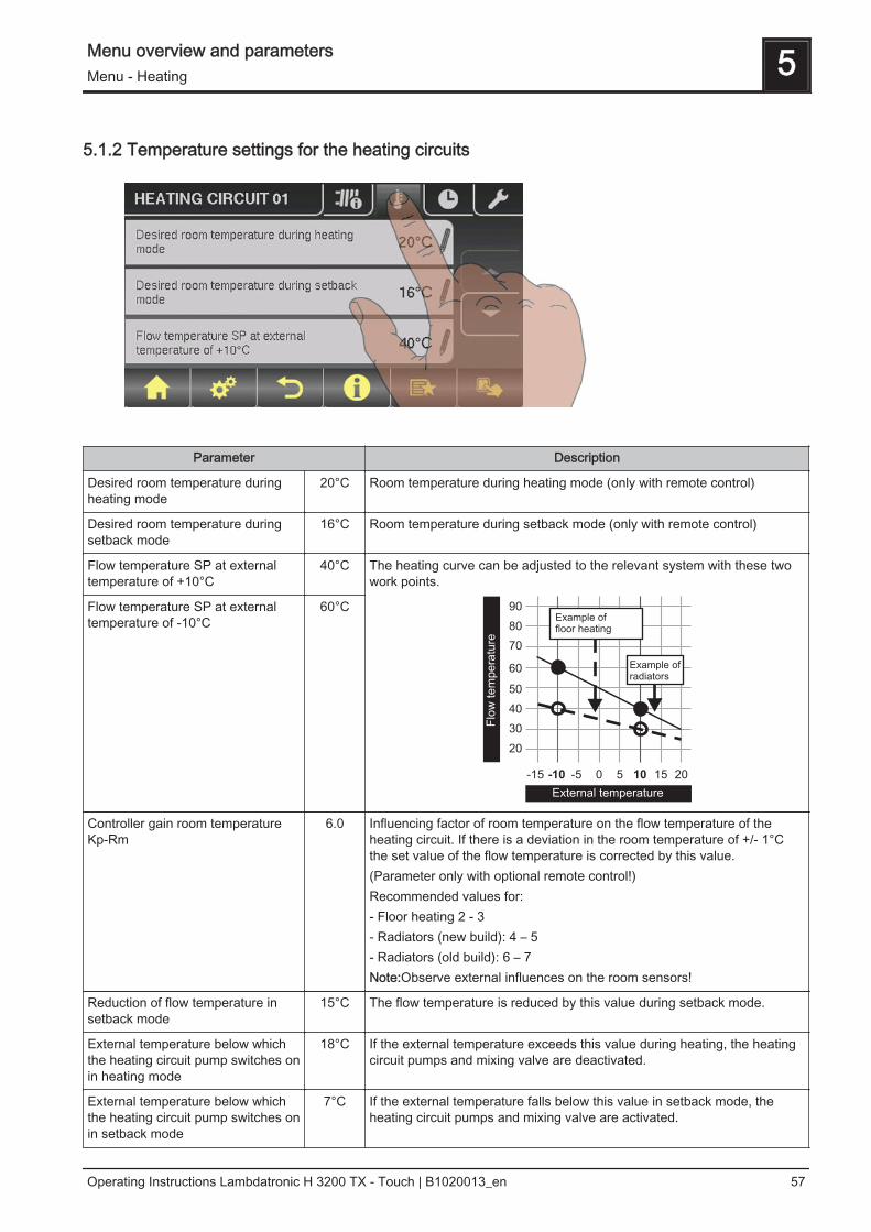
5.1.2 Temperature settings for the heating circuits
Parameter Description
Desired room temperature duringheating mode
20°C Room temperature during heating mode (only with remote control)
Desired room temperature duringsetback mode
16°C Room temperature during setback mode (only with remote control)
Flow temperature SP at externaltemperature of +10°C
40°C The heating curve can be adjusted to the relevant system with these twowork points.
90
80
70
60
50
40
30
20
Flo
w tem
pera
ture
-10
External temperature
-15 -5 0 5 10 15 20
Example offloor heating
Example ofradiators
Flow temperature SP at externaltemperature of -10°C
60°C
Controller gain room temperatureKp-Rm
6.0 Influencing factor of room temperature on the flow temperature of theheating circuit. If there is a deviation in the room temperature of +/- 1°Cthe set value of the flow temperature is corrected by this value.(Parameter only with optional remote control!)Recommended values for:- Floor heating 2 - 3- Radiators (new build): 4 – 5- Radiators (old build): 6 – 7Note:Observe external influences on the room sensors!
Reduction of flow temperature insetback mode
15°C The flow temperature is reduced by this value during setback mode.
External temperature below whichthe heating circuit pump switches onin heating mode
18°C If the external temperature exceeds this value during heating, the heatingcircuit pumps and mixing valve are deactivated.
External temperature below whichthe heating circuit pump switches onin setback mode
7°C If the external temperature falls below this value in setback mode, theheating circuit pumps and mixing valve are activated.
Menu overview and parameters 5Menu - Heating
Operating Instructions Lambdatronic H 3200 TX - Touch | B1020013_en 57
Maximum heating circuit flow temp. 75°C Maximum temperature for limiting outfeed temperature at which the heat‐ing circuit is supplied.
Maximum DHW tank flow temp. 75°C If DHW tank 1 is supplied directly from heating circuit 1, you can set anoth‐er maximum flow temperature for the time of DHW tank loading.
Frost protection temperature 10°C If the room temperature or the flow temperature is lower than the set val‐ue, the heating circuit pump will be switched on.
5.1.3 Heating times of the heating circuits
⇨ See "Setting times" [page 36]
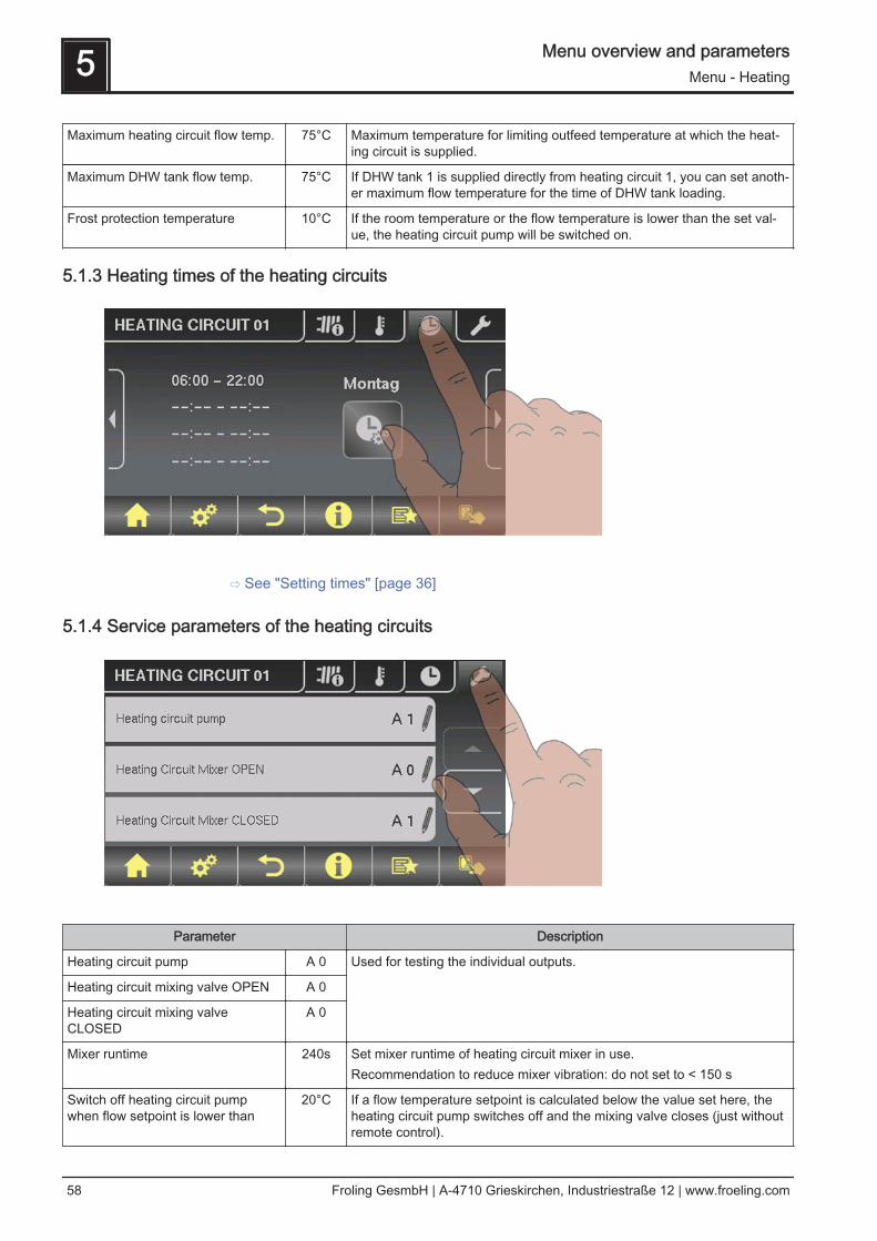
5.1.4 Service parameters of the heating circuits
Parameter Description
Heating circuit pump A 0 Used for testing the individual outputs.
Heating circuit mixing valve OPEN A 0
Heating circuit mixing valveCLOSED
A 0
Mixer runtime 240s Set mixer runtime of heating circuit mixer in use.Recommendation to reduce mixer vibration: do not set to < 150 s
Switch off heating circuit pumpwhen flow setpoint is lower than
20°C If a flow temperature setpoint is calculated below the value set here, theheating circuit pump switches off and the mixing valve closes (just withoutremote control).
5 Menu overview and parametersMenu - Heating
58 Froling GesmbH | A-4710 Grieskirchen, Industriestraße 12 | www.froeling.com

Parameter Description
Should this heating circuit heatwhen there is DHW tank priority?
NO Generally the heating circuits are released with active DHW tank priorityonly when the DHW tank is fully charged. If this parameter is set to "YES",the DHW tank priority for this heating circuit is deactivated.
From which storage tank or distribu‐tor is the heating circuit supplied (0= boiler)
1 NOTE: Only valid for multiple house systems (variants).Allocation of the heating source for this heating circuit:0 = Boiler, 1 = Storage tank 01, ...
High temperature requirement be‐cause of DHW tank 1 loading
NO If DHW tank 1 is supplied directly from the heating circuit as well as theisolating valve, this parameter must be set to “YES”. If there is a require‐ment from the DHW tank and the criteria for DHW tank loading have beenmet, the isolating valve immediately clears the way for boiler loading. Theheating circuit pump starts running as soon as the “Load if tempera-ture difference between boiler and DHW tank is” criterionis reached. Once DHW tank loading is complete, the heating circuit pumpwill stop, the isolating valve will remain active for a specified period of timeand the heating circuit mixer will close. If time has run out, the heating cir‐cuit will go back to being supplied on a weather-compensated basis.NOTE: Parameter only available with heating circuit 1 and generally onlyused in conjunction with the unit model of the P1 Pellet pellet boiler!
High temperature requirement be‐cause of DHW tank loading
NO If this parameter is set to YES, the remote line is operated according tothe set heating curve + overcharge. Whilst the DHW tank is loading, theremote line is supplied for a short time at a higher temperature, but oncethe DHW tank is loaded, it is supplied again according to the heatingcurve.NOTE: Parameters for heating circuit 2 only!
For high temperature requirementdon't look at DHW tank 01
NO If DHW tank 1 is positioned in front of the network mixer, it should not af‐fect the temperature control of the remote line, therefore this parametershould be set to YES.NOTE: Parameters for heating circuit 2 only!
⇨ See "Digital outputs" [page 93]
5.1.5 Service parameters for heating up program
Parameter Description
Heating up program active NO If this parameter is activated, the 30-day program that has been set starts.After the 30 days the heating circuit that has been set operates normallyagain.
Current day of the heating up pro‐gram
1 Shows the current day of the heating program that is running
Menu overview and parameters 5Menu - Heating
Operating Instructions Lambdatronic H 3200 TX - Touch | B1020013_en 59

Parameter Description
For which heating circuit should theprogram apply
1 This parameter determines which heating circuit is supplied by the heatingup program. Heating circuit 1 ... 18❒ Only one heating circuit can be selected.
Which heating up program is used 1 There are set options for the progression of the flow temperature in heat‐ing up programs 1 – 6. With heating up program 7 the flow temperaturecan be selected freely.
Outfeed setpoint for all days in pro‐gram 7
35°C If heating up program 7 is active, the selected heating circuit is adjusted tothe specified flow temperature.
⇨ See "Heating up programs" [page 60]
Heating up programs
Heating up program 1:
0
5
10
15
20
25
30
35
40
45
50
55
1 6 11 16 21 26
Day
Flo
wte
mp
.setp
oin
t[°
C]
30
Heating up program 5:
0
5
10
15
20
25
30
35
40
45
50
55
1 6 11 16 21 26
Day
Flo
wte
mp
.setp
oin
t[°
C]
30
Heating up program 2:
0
5
10
15
20
25
30
35
40
45
50
1 6 11 16 21 26
Day
Flo
wte
mp
.setp
oin
t[°
C]
30
Heating up program 6:
0
5
10
15
20
25
30
35
40
45
50
55
60
1 6 11 16 21 26
Day
Flo
wte
mp
.setp
oin
t[°
C]
30
5 Menu overview and parametersMenu - Heating
60 Froling GesmbH | A-4710 Grieskirchen, Industriestraße 12 | www.froeling.com
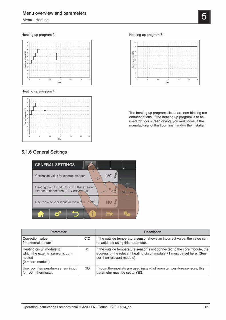
Heating up program 3:
0
5
10
15
20
25
30
35
40
45
50
1 6 11 16 21 26
Day
Flo
wte
mp
.setp
oin
t[°
C]
30
Heating up program 7:
0
5
10
15
20
25
30
35
40
1 6 11 16 21 26
Day
Flo
wte
mp
.setp
oin
t[°
C]
30
Heating up program 4:
0
5
10
15
20
25
30
35
40
45
1 6 11 16 21 26
Day
Flo
wte
mp
.setp
oin
t[°
C]
30
The heating up programs listed are non-binding rec‐ommendations. If the heating up program is to beused for floor screed drying, you must consult themanufacturer of the floor finish and/or the installer
5.1.6 General Settings
Parameter Description
Correction value for external sensor
0°C If the outside temperature sensor shows an incorrect value, the value canbe adjusted using this parameter.
Heating circuit module to which the external sensor is con‐nected(0 = core module)
0 If the outside temperature sensor is not connected to the core module, theaddress of the relevant heating circuit module +1 must be set here. (Sen‐sor 1 on relevant module)
Use room temperature sensor inputfor room thermostat
NO If room thermostats are used instead of room temperature sensors, thisparameter must be set to YES.
Menu overview and parameters 5Menu - Heating
Operating Instructions Lambdatronic H 3200 TX - Touch | B1020013_en 61

5.2 Menu - Water
⇨ See "Navigation within the system menu" [page 33]
5.2.1 Status displays for the DHW tank
Parameter Description
DHW tank top temperature 60°C Current temperature in the top part of the DHW tank. The DHW tank isheated during the loading times until the specified parameter, "Set DHWtemperature", is reached.
DHW tank bottom temperature 55°C Current temperature in the lower part of the DHW tank.(Parameter only available with solar element)
DHW tank pump control 0% Specifies the speed of the DHW tank pump as a percentage of the maxi‐mum speed
5.2.2 Temperature settings of the DHW tank
Parameter Description
DHW setpoint 55°C When this DHW tank temperature is reached the DHW tank loading pumpswitches off.
Reload if DHW tank temperature isbelow
45°C Reloading of the DHW tank is authorised when the DHW tank temperatureis below this level.
5 Menu overview and parametersMenu - Water
62 Froling GesmbH | A-4710 Grieskirchen, Industriestraße 12 | www.froeling.com

Load if temperature difference be‐tween storage tank and DHW tankis
6°C When the storage tank top temperature is above the DHW tank tempera‐ture by this value, the DHW tank loading pump is released.(Only for systems with storage tanks)
Load if temperature difference be‐tween boiler and DHW tank is
6°C Initial value of DHW tank loading. The boiler temperature must be higherthan the DHW tank temperature by this value so that the DHW tank load‐ing process begins.(Only for systems without storage tanks)
Setpoint for temperature differencebetween boiler - DHW tank
10°C Adjusting the boiler temperature setpoint to reach the desired DHW tanktemperature.Boiler temperature setpoint = DHW tank temperature setpoint + differenceIf the boiler temperature setpoint is higher than the DHW temperature set‐point + difference, the boiler temperature setpoint is maintained.(Only for systems without storage tanks)
5.2.3 Heating times of the DHW tank
⇨ See "Setting times" [page 36]
5.2.4 Service parameters of the DHW tank
Menu overview and parameters 5Menu - Water
Operating Instructions Lambdatronic H 3200 TX - Touch | B1020013_en 63

Parameter Description
Residual heat use NO Function can only be used with systems with return mixer and no storagetank. This diverts the residual energy to the DHW tank, the "AboveBoiler temp pumps start” parameter is ignored. The pump is acti‐vated at minimum speed until the boiler temperature is lower than theDHW tank temperature + 3°C.
Only load DHW tank once a day NO If this parameter is set to "YES", repeated heating on one day is preven‐ted.
Legionella heating activated YES The DHW tank is heated to at least 65°C once a week.
Which day for legionella heating MO Day of the week on which the Legionella heating is carried out.
Which storage tank or heat distribu‐tor supplies the heat to this DHWtank (0 = boiler)
1 When using several storage tanks or heat distributors, the source of heatfor DHW tank loading is selected here.If only one storage tank or heat distributor is used, leave the parameter atthe default setting of 1.NOTE: Only valid for multiple house systems.
DHW tanks run-on (this parameterapplies for all DHW tanks)
0m Run-on time for all DHW tanks
Which sensor is used for top DHWtank 1
0.3 Bus address of the sensors and pumps used.⇨ See "Setting the module address" [page 22] Which sensor is used for solar refer‐
ence DHW tank 10.4
Which pump is used for DHW tank 1 0.2
PWM setting for DHW tank pump Normalpump
▪ Normal pump▪ PWM / field pump▪ PWM / solar pump▪ PWM field pump + valve▪ 0 – 10V / field pump▪ 0 – 10V / solar pump▪ 0 – 10V field pump + valve
Properties of the respective setting:⇨ See "PWM / 0 - 10V settings" [page 114]
Minimum DHW tank pump speed 45% Adjustment of the minimum speed to the pump type. (Set the pump modeaccording to pump manufacturer’s instructions)
Maximum DHW tank pump speed 100% If you need to limit the maximum speed of the DHW tank pump for system‐ic reasons, you can do so by adjusting this parameter.
5 Menu overview and parametersMenu - Solar
64 Froling GesmbH | A-4710 Grieskirchen, Industriestraße 12 | www.froeling.com

5.3 Menu - Solar
⇨ See "Navigation within the system menu" [page 33]
5.3.1 Status displays for the solar system
Parameter Description
Collector Temperature 80°C Current temperature at collector.
Solar temperature bottom storagetank
43°C Current temperature at solar sensor at bottom of storage tank.
DHW tank bottom temperature 39°C Current temperature at the solar reference sensor in the DHW tank.
Collector return feed temperature 50°C Current temperature at collector return.(Only for systems 12, 13)
Heat exchanger sec. return feedtemperature (line to storage tank)
78°C Current temperature at heat exchanger flow on the secondary side. (Onlyfor systems 12,13)
Collector pump runtime 1h Specifies the runtime of the collector pump.
Collector pump control 52% Specifies the speed of the collector pump as a percentage of maximumspeed.
Pump between heat exchanger andstorage tank
100% Current speed of the pump between heat exchanger and storage tank(Only for systems 12, 13)
Pump between heat exchanger andDHW tank
0% Current speed of the pump between heat exchanger and DHW tank (Onlyfor system 12)
Diverter valve for top/bottom coils 0% Current control of the isolating valve on the solar side. If the valve is cor‐rectly fitted:0% … bottom storage tank100% … top storage tankIf the valve is incorrectly fitted, the output of the isolating valve can be in‐verted in the Service menu.Service parameters of the solar system(Only for systems 12, 13)
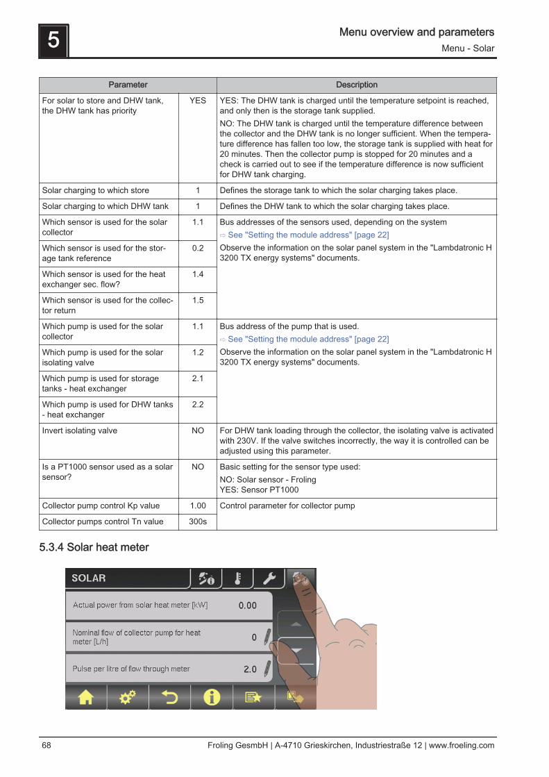
Outfeed: 0 °C / Return: NAP: 0.0 kW / DFL: 0Today: 0 kWhTotal: 0 kWh
Solar heat meter:Outfeed: flow temperature of the solar panel systemReturn: return of the solar panel systemP: current output of the solar panel systemDFL: flow-through of the solar panel systemToday: heat quantity that has been supplied by the solar panel system to‐dayTotal: heat quantity that has been supplied since activation of the solarpanel system
Menu overview and parameters 5Menu - Solar
Operating Instructions Lambdatronic H 3200 TX - Touch | B1020013_en 65
5.3.2 Temperature settings for the solar system
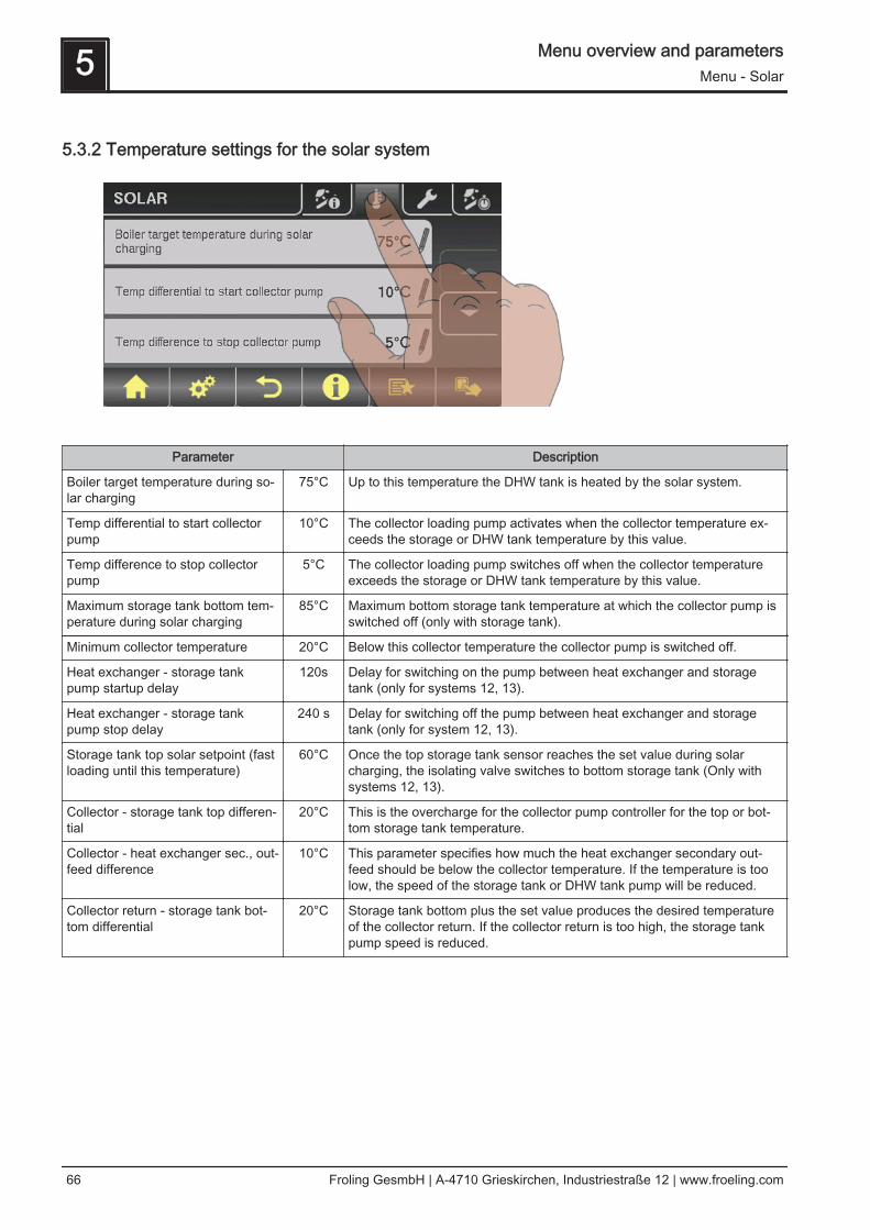
Parameter Description
Boiler target temperature during so‐lar charging
75°C Up to this temperature the DHW tank is heated by the solar system.
Temp differential to start collectorpump
10°C The collector loading pump activates when the collector temperature ex‐ceeds the storage or DHW tank temperature by this value.
Temp difference to stop collectorpump
5°C The collector loading pump switches off when the collector temperatureexceeds the storage or DHW tank temperature by this value.
Maximum storage tank bottom tem‐perature during solar charging
85°C Maximum bottom storage tank temperature at which the collector pump isswitched off (only with storage tank).
Minimum collector temperature 20°C Below this collector temperature the collector pump is switched off.
Heat exchanger - storage tankpump startup delay
120s Delay for switching on the pump between heat exchanger and storagetank (only for systems 12, 13).
Heat exchanger - storage tankpump stop delay
240 s Delay for switching off the pump between heat exchanger and storagetank (only for system 12, 13).
Storage tank top solar setpoint (fastloading until this temperature)
60°C Once the top storage tank sensor reaches the set value during solarcharging, the isolating valve switches to bottom storage tank (Only withsystems 12, 13).
Collector - storage tank top differen‐tial
20°C This is the overcharge for the collector pump controller for the top or bot‐tom storage tank temperature.
Collector - heat exchanger sec., out‐feed difference
10°C This parameter specifies how much the heat exchanger secondary out‐feed should be below the collector temperature. If the temperature is toolow, the speed of the storage tank or DHW tank pump will be reduced.
Collector return - storage tank bot‐tom differential
20°C Storage tank bottom plus the set value produces the desired temperatureof the collector return. If the collector return is too high, the storage tankpump speed is reduced.
5 Menu overview and parametersMenu - Solar
66 Froling GesmbH | A-4710 Grieskirchen, Industriestraße 12 | www.froeling.com

5.3.3 Service parameters of the solar system
Parameter Description
Solar system 1 Specifies the type of solar system. The parameter should be set accordingto the solar diagram.1: Solar panel system only on domestic hot water tank2: Solar panel system only on storage tank3: Solar panel system with isolating valve (switch from domestic hot watertank to storage tank, or between top and bottom solar elements with theH3 hygienic solar layered tank)Observe the information on the solar panel system in the "Lambdatronic H3200 TX energy systems" documents.
PWM setting for solar collectorpump
Normalpump
▪ Normal pump▪ PWM / field pump▪ PWM / solar pump▪ PWM field pump + valve▪ 0 – 10V / field pump▪ 0 – 10V / solar pump▪ 0 – 10V field pump + valve
Properties of the respective setting:⇨ See "PWM / 0 - 10V settings" [page 114]
Minimum collector pump speed 45% Adjustment of the minimum speed to the pump type. (Set the pump modeaccording to pump manufacturer’s instructions)
Maximum collector pump speed 100% If you need to limit the maximum speed of the collector pump for systemicreasons, you can do so by adjusting this parameter.
Collector monitoring → Collectorpump is switched on every 30 min.for 10 sec
NO If this parameter is active the collector pump is switched on every 30 mi‐nutes for 10 seconds. If the collector sensor detects an increase in tem‐perature, the pump is kept on.This function is active from 10:00am - 7:00pm and the threshold value ofthe collector temperature, from which this function is active, is dynamicallyadjusted.
Menu overview and parameters 5Menu - Solar
Operating Instructions Lambdatronic H 3200 TX - Touch | B1020013_en 67
Parameter Description
For solar to store and DHW tank,the DHW tank has priority
YES YES: The DHW tank is charged until the temperature setpoint is reached,and only then is the storage tank supplied.NO: The DHW tank is charged until the temperature difference betweenthe collector and the DHW tank is no longer sufficient. When the tempera‐ture difference has fallen too low, the storage tank is supplied with heat for20 minutes. Then the collector pump is stopped for 20 minutes and acheck is carried out to see if the temperature difference is now sufficientfor DHW tank charging.
Solar charging to which store 1 Defines the storage tank to which the solar charging takes place.
Solar charging to which DHW tank 1 Defines the DHW tank to which the solar charging takes place.
Which sensor is used for the solarcollector
1.1 Bus addresses of the sensors used, depending on the system⇨ See "Setting the module address" [page 22]Observe the information on the solar panel system in the "Lambdatronic H3200 TX energy systems" documents.
Which sensor is used for the stor‐age tank reference
0.2
Which sensor is used for the heatexchanger sec. flow?
1.4
Which sensor is used for the collec‐tor return
1.5
Which pump is used for the solarcollector
1.1 Bus address of the pump that is used.⇨ See "Setting the module address" [page 22]Observe the information on the solar panel system in the "Lambdatronic H3200 TX energy systems" documents.
Which pump is used for the solarisolating valve
1.2
Which pump is used for storagetanks - heat exchanger
2.1
Which pump is used for DHW tanks- heat exchanger
2.2
Invert isolating valve NO For DHW tank loading through the collector, the isolating valve is activatedwith 230V. If the valve switches incorrectly, the way it is controlled can beadjusted using this parameter.
Is a PT1000 sensor used as a solarsensor?
NO Basic setting for the sensor type used:NO: Solar sensor - FrolingYES: Sensor PT1000
Collector pump control Kp value 1.00 Control parameter for collector pump
Collector pumps control Tn value 300s
5.3.4 Solar heat meter
5 Menu overview and parametersMenu - Solar
68 Froling GesmbH | A-4710 Grieskirchen, Industriestraße 12 | www.froeling.com
Parameter Description
Outfeed: 0 °C / Return: NAP: 0.0kW / DFL: 0Today: 0 kWhTotal: 0 kWh
Solar heat meter:Outfeed: flow temperature of the solar panel systemReturn: return of the solar panel systemP: current output of the solar panel systemDFL: flow-through of the solar panel systemToday: heat quantity that has been supplied by the solar panel system to‐dayTotal: heat quantity that has been supplied since activation of the solarpanel system
Current output of Solar WMZ [kW] 0.00 Displays current output of solar collector.
Nominal flow of collector pump forheat meter [L/h]
0 Sets the nominal flow of the collector pump used.This setting can be ignored if using an external flow meter.
Pulses per litre from the flow sensor 2.0 If an external flow meter is used, adjust this value according to the deviceused. [0.5 – 5 pulses/L]
Which sensor is used for the collec‐tor return
1.5 Bus addresses of the sensors used, depending on the system⇨ See "Setting the module address" [page 22]
Which sensor is used for heat meterflow temperature
1.3 If a flow temperature sensor is used for the heat meter in addition to thecollector sensor, set the sensor address accordingly.Bus addresses of the sensors used, depending on the system⇨ See "Setting the module address" [page 22]
Is an external flow through counterused
NO If an external volume flow sensor is used in the collector return, set thisparameter to “YES”.
Menu overview and parameters 5Menu - Storage tank
Operating Instructions Lambdatronic H 3200 TX - Touch | B1020013_en 69

5.4 Menu - Storage tank
⇨ See "Navigation within the system menu" [page 33]
5.4.1 Status displays of the storage tank
Parameter Description
Storage tank top temperature 58°C Current temperature at top storage tank sensor.
Storage tank temperature, sensor 2 55°C Only for the master boiler in the cascade.
Storage tank temperature, sensor 3 54°C Only for the master boiler in the cascade.
Storage tank middle temperature 53°C Current temperature at middle storage tank sensor (depending on configu‐ration).
Storage tank bottom temperature 50°C Current temperature at bottom storage tank sensor.
Store pump control 50% Specifies the current speed of the storage tank pump as a percentage ofthe maximum speed.
Store charge 25% Only for the master boiler in the cascade or system 4. Shows the currentstorage tank charge.
5.4.2 Temperature settings for the storage tank
5 Menu overview and parametersMenu - Storage tank
70 Froling GesmbH | A-4710 Grieskirchen, Industriestraße 12 | www.froeling.com
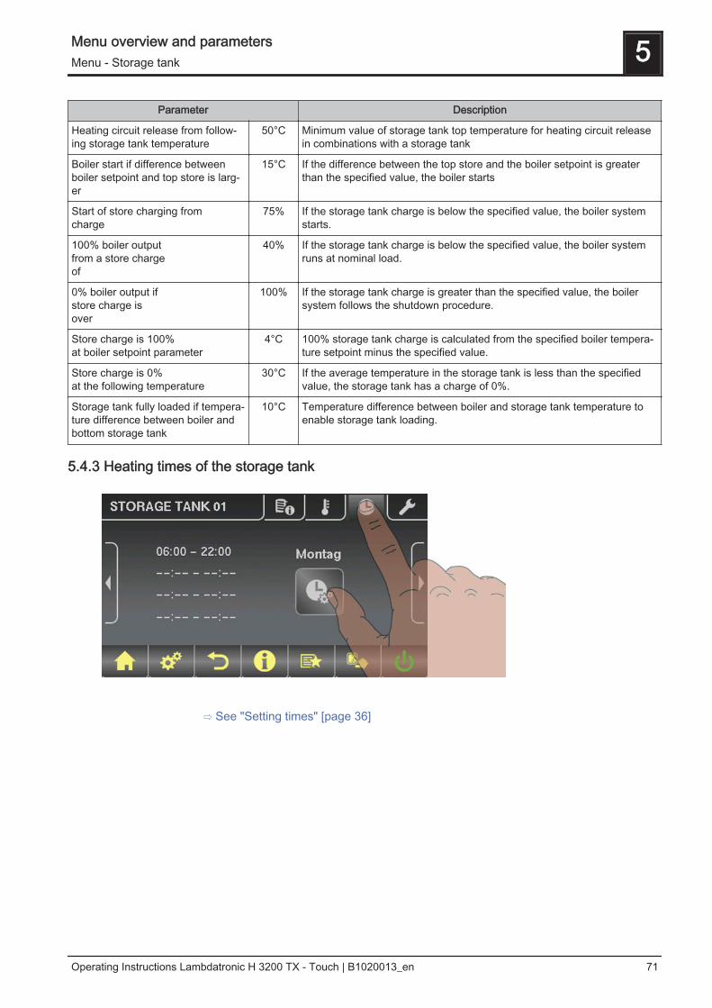
Parameter Description
Heating circuit release from follow‐ing storage tank temperature
50°C Minimum value of storage tank top temperature for heating circuit releasein combinations with a storage tank
Boiler start if difference betweenboiler setpoint and top store is larg‐er
15°C If the difference between the top store and the boiler setpoint is greaterthan the specified value, the boiler starts
Start of store charging fromcharge
75% If the storage tank charge is below the specified value, the boiler systemstarts.
100% boiler outputfrom a store chargeof
40% If the storage tank charge is below the specified value, the boiler systemruns at nominal load.
0% boiler output ifstore charge isover
100% If the storage tank charge is greater than the specified value, the boilersystem follows the shutdown procedure.
Store charge is 100%at boiler setpoint parameter
4°C 100% storage tank charge is calculated from the specified boiler tempera‐ture setpoint minus the specified value.
Store charge is 0%at the following temperature
30°C If the average temperature in the storage tank is less than the specifiedvalue, the storage tank has a charge of 0%.
Storage tank fully loaded if tempera‐ture difference between boiler andbottom storage tank
10°C Temperature difference between boiler and storage tank temperature toenable storage tank loading.
5.4.3 Heating times of the storage tank
⇨ See "Setting times" [page 36]
Menu overview and parameters 5Menu - Storage tank
Operating Instructions Lambdatronic H 3200 TX - Touch | B1020013_en 71
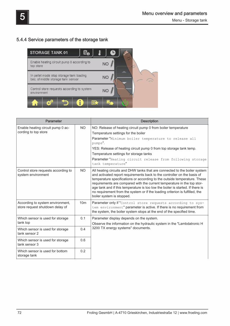
5.4.4 Service parameters of the storage tank
Parameter Description
Enable heating circuit pump 0 ac‐cording to top store
NO NO: Release of heating circuit pump 0 from boiler temperatureTemperature settings for the boilerParameter "Minimum boiler temperature to release allpumps".YES: Release of heating circuit pump 0 from top storage tank temp.Temperature settings for storage tanksParameter "Heating circuit release from following storagetank temperature"
Control store requests according tosystem environment
NO All heating circuits and DHW tanks that are connected to the boiler systemand activated report requirements back to the controller on the basis oftemperature specifications or according to the outside temperature. Theserequirements are compared with the current temperature in the top stor‐age tank and if this temperature is too low the boiler is started. If there isno requirement from the system or if the loading criterion is fulfilled, theboiler system is stopped.
According to system environment,store request shutdown delay of
10m Parameter only if "Control store requests according to sys-tem environment" parameter is active. If there is no requirement fromthe system, the boiler system stops at the end of the specified time.
Which sensor is used for storagetank top
0.1 Parameter display depends on the system.Observe the information on the hydraulic system in the "Lambdatronic H3200 TX energy systems" documents.Which sensor is used for storage
tank sensor 20.4
Which sensor is used for storagetank sensor 3
0.6
Which sensor is used for bottomstorage tank
0.2
5 Menu overview and parametersMenu - Storage tank
72 Froling GesmbH | A-4710 Grieskirchen, Industriestraße 12 | www.froeling.com
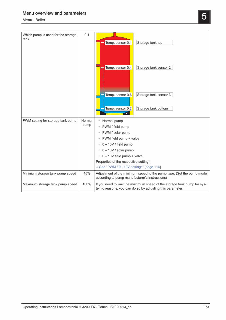
Which pump is used for the storagetank
0.1
PWM setting for storage tank pump Normalpump
▪ Normal pump▪ PWM / field pump▪ PWM / solar pump▪ PWM field pump + valve▪ 0 – 10V / field pump▪ 0 – 10V / solar pump▪ 0 – 10V field pump + valve
Properties of the respective setting:⇨ See "PWM / 0 - 10V settings" [page 114]
Minimum storage tank pump speed 45% Adjustment of the minimum speed to the pump type. (Set the pump modeaccording to pump manufacturer’s instructions)
Maximum storage tank pump speed 100% If you need to limit the maximum speed of the storage tank pump for sys‐temic reasons, you can do so by adjusting this parameter.
Menu overview and parameters 5Menu - Boiler
Operating Instructions Lambdatronic H 3200 TX - Touch | B1020013_en 73
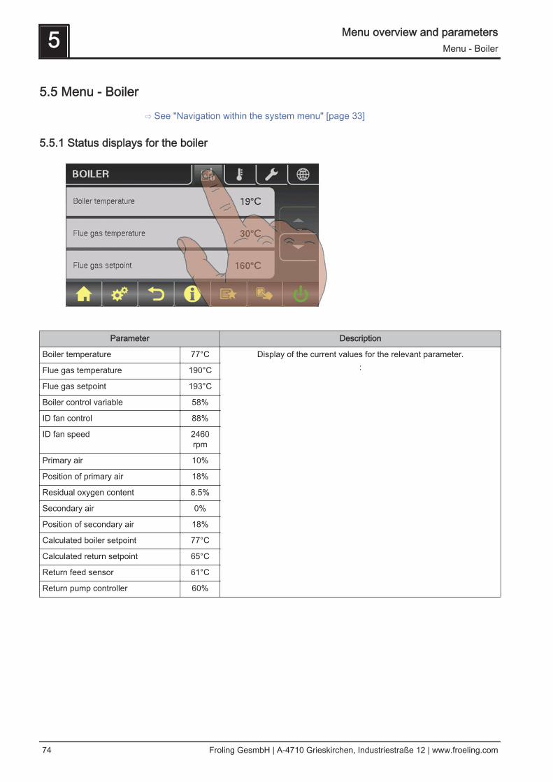
5.5 Menu - Boiler
⇨ See "Navigation within the system menu" [page 33]
5.5.1 Status displays for the boiler
Parameter Description
Boiler temperature 77°C Display of the current values for the relevant parameter.:
Flue gas temperature 190°C
Flue gas setpoint 193°C
Boiler control variable 58%
ID fan control 88%
ID fan speed 2460rpm
Primary air 10%
Position of primary air 18%
Residual oxygen content 8.5%
Secondary air 0%
Position of secondary air 18%
Calculated boiler setpoint 77°C
Calculated return setpoint 65°C
Return feed sensor 61°C
Return pump controller 60%
5 Menu overview and parametersMenu - Boiler
74 Froling GesmbH | A-4710 Grieskirchen, Industriestraße 12 | www.froeling.com
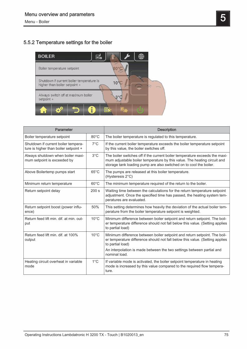
5.5.2 Temperature settings for the boiler
Parameter Description
Boiler temperature setpoint 80°C The boiler temperature is regulated to this temperature.
Shutdown if current boiler tempera‐ture is higher than boiler setpoint +
7°C If the current boiler temperature exceeds the boiler temperature setpointby this value, the boiler switches off.
Always shutdown when boiler maxi‐mum setpoint is exceeded by
3°C The boiler switches off if the current boiler temperature exceeds the maxi‐mum adjustable boiler temperature by this value. The heating circuit andstorage tank loading pump are also switched on to cool the boiler.
Above Boilertemp pumps start 65°C The pumps are released at this boiler temperature.(Hysteresis 2°C)
Minimum return temperature 60°C The minimum temperature required of the return to the boiler.
Return setpoint delay 200 s Waiting time between the calculations for the return temperature setpointadjustment. Once the specified time has passed, the heating system tem‐peratures are evaluated.
Return setpoint boost (power influ‐ence)
50% This setting determines how heavily the deviation of the actual boiler tem‐perature from the boiler temperature setpoint is weighted.
Return feed lift min. dif. at min. out‐put
10°C Minimum difference between boiler setpoint and return setpoint. The boil‐er temperature difference should not fall below this value. (Setting appliesto partial load)
Return feed lift min. dif. at 100%output
10°C Minimum difference between boiler setpoint and return setpoint. The boil‐er temperature difference should not fall below this value. (Setting appliesto partial load)An interpolation is made between the two settings between partial andnominal load.
Heating circuit overheat in variablemode
1°C If variable mode is activated, the boiler setpoint temperature in heatingmode is increased by this value compared to the required flow tempera‐ture.
Menu overview and parameters 5Menu - Boiler
Operating Instructions Lambdatronic H 3200 TX - Touch | B1020013_en 75
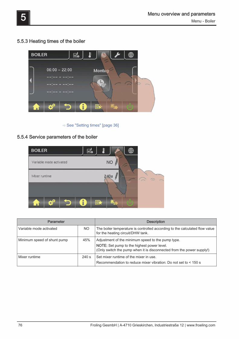
5.5.3 Heating times of the boiler
⇨ See "Setting times" [page 36]
5.5.4 Service parameters of the boiler
Parameter Description
Variable mode activated NO The boiler temperature is controlled according to the calculated flow valuefor the heating circuit/DHW tank.
Minimum speed of shunt pump 45% Adjustment of the minimum speed to the pump type.NOTE: Set pump to the highest power level.(Only switch the pump when it is disconnected from the power supply!)
Mixer runtime 240 s Set mixer runtime of the mixer in use.Recommendation to reduce mixer vibration: Do not set to < 150 s
5 Menu overview and parametersMenu - Boiler
76 Froling GesmbH | A-4710 Grieskirchen, Industriestraße 12 | www.froeling.com

5.5.5 General Settings
Parameter Description
Modem installed NO If the boiler has a modem for data transfer, this value must be set to"YES".
Memory cycle of data logger 5 s Leave the value!This is the memory cycle used for saving data on the data logger.
Output warnings through fault mes‐sage relays
NO If this parameter is set to "YES", warnings from the boiler system are alsodisplayed on the fault message relay.
COM 2 is used as a MODBUS inter‐face
NO YES:The COM 2 interface can be used to connect a MODBUS (RTU/ASCII)NO:The COM 2 interface sends the most important boiler values every sec‐ond
MODBUS address 2 Adjustable parameters for MODBUS
MODBUS protocol (1 – RTU / 2 –ASCII)
1
Menu overview and parameters 5Menu - Boiler
Operating Instructions Lambdatronic H 3200 TX - Touch | B1020013_en 77
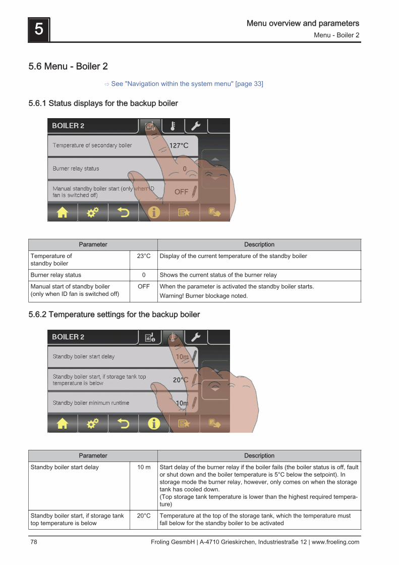
5.6 Menu - Boiler 2
⇨ See "Navigation within the system menu" [page 33]
5.6.1 Status displays for the backup boiler
Parameter Description
Temperature of standby boiler
23°C Display of the current temperature of the standby boiler
Burner relay status 0 Shows the current status of the burner relay
Manual start of standby boiler(only when ID fan is switched off)
OFF When the parameter is activated the standby boiler starts.Warning! Burner blockage noted.
5.6.2 Temperature settings for the backup boiler
Parameter Description
Standby boiler start delay 10 m Start delay of the burner relay if the boiler fails (the boiler status is off, faultor shut down and the boiler temperature is 5°C below the setpoint). Instorage mode the burner relay, however, only comes on when the storagetank has cooled down.(Top storage tank temperature is lower than the highest required tempera‐ture)
Standby boiler start, if storage tanktop temperature is below
20°C Temperature at the top of the storage tank, which the temperature mustfall below for the standby boiler to be activated
5 Menu overview and parametersMenu - Boiler 2
78 Froling GesmbH | A-4710 Grieskirchen, Industriestraße 12 | www.froeling.com
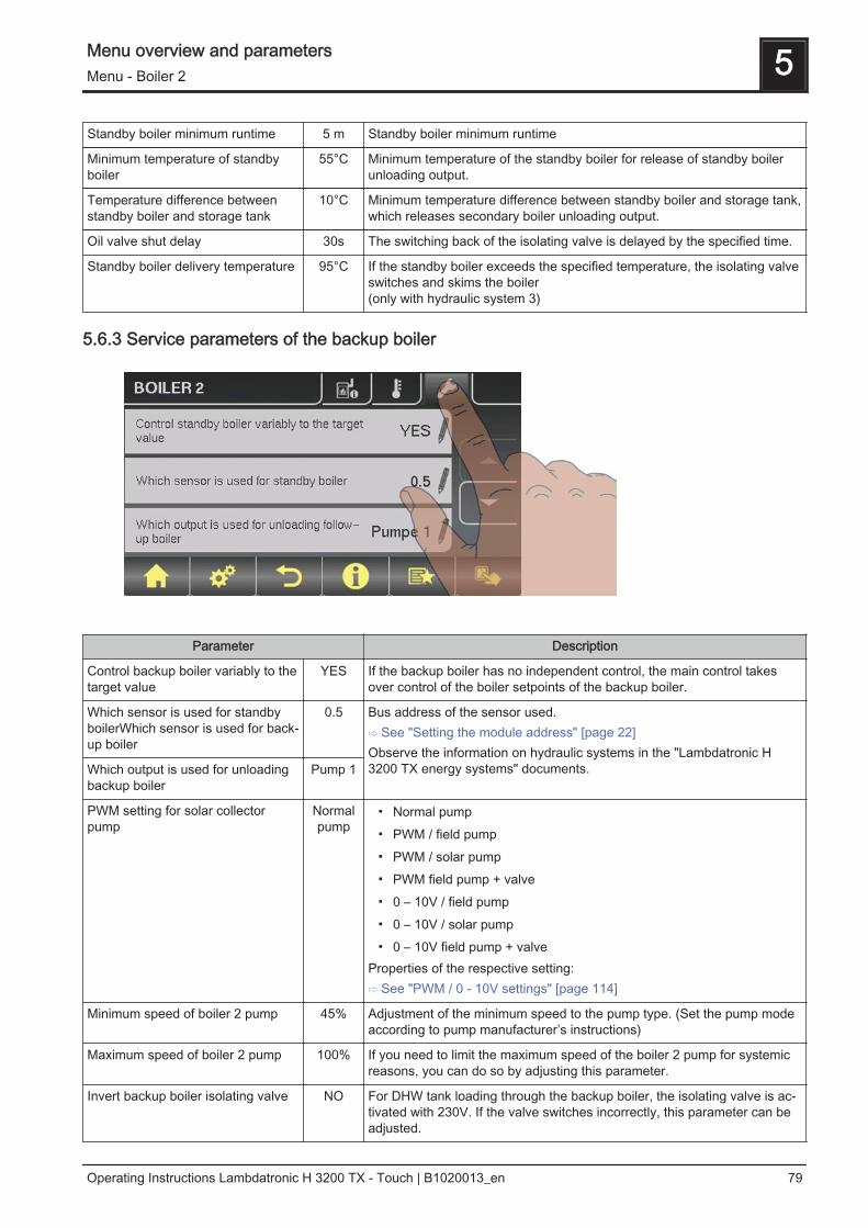
Standby boiler minimum runtime 5 m Standby boiler minimum runtime
Minimum temperature of standbyboiler
55°C Minimum temperature of the standby boiler for release of standby boilerunloading output.
Temperature difference betweenstandby boiler and storage tank
10°C Minimum temperature difference between standby boiler and storage tank,which releases secondary boiler unloading output.
Oil valve shut delay 30s The switching back of the isolating valve is delayed by the specified time.
Standby boiler delivery temperature 95°C If the standby boiler exceeds the specified temperature, the isolating valveswitches and skims the boiler(only with hydraulic system 3)
5.6.3 Service parameters of the backup boiler
Parameter Description
Control backup boiler variably to thetarget value
YES If the backup boiler has no independent control, the main control takesover control of the boiler setpoints of the backup boiler.
Which sensor is used for standbyboilerWhich sensor is used for back‐up boiler
0.5 Bus address of the sensor used.⇨ See "Setting the module address" [page 22]Observe the information on hydraulic systems in the "Lambdatronic H3200 TX energy systems" documents.Which output is used for unloading
backup boilerPump 1
PWM setting for solar collectorpump
Normalpump
▪ Normal pump▪ PWM / field pump▪ PWM / solar pump▪ PWM field pump + valve▪ 0 – 10V / field pump▪ 0 – 10V / solar pump▪ 0 – 10V field pump + valve
Properties of the respective setting:⇨ See "PWM / 0 - 10V settings" [page 114]
Minimum speed of boiler 2 pump 45% Adjustment of the minimum speed to the pump type. (Set the pump modeaccording to pump manufacturer’s instructions)
Maximum speed of boiler 2 pump 100% If you need to limit the maximum speed of the boiler 2 pump for systemicreasons, you can do so by adjusting this parameter.
Invert backup boiler isolating valve NO For DHW tank loading through the backup boiler, the isolating valve is ac‐tivated with 230V. If the valve switches incorrectly, this parameter can beadjusted.
Menu overview and parameters 5Menu - Boiler 2
Operating Instructions Lambdatronic H 3200 TX - Touch | B1020013_en 79
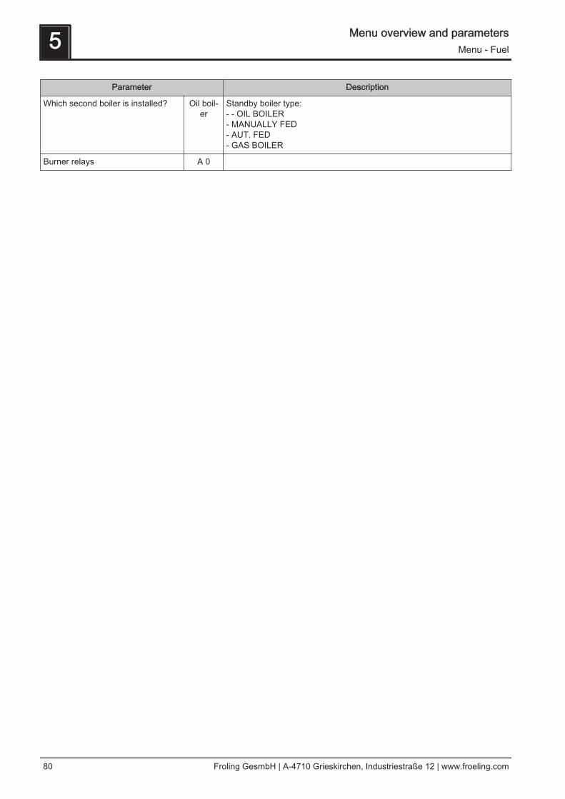
Parameter Description
Which second boiler is installed? Oil boil‐er
Standby boiler type:- - OIL BOILER - MANUALLY FED - AUT. FED- GAS BOILER
Burner relays A 0
5 Menu overview and parametersMenu - Fuel
80 Froling GesmbH | A-4710 Grieskirchen, Industriestraße 12 | www.froeling.com

5.7 Menu - Fuel
⇨ See "Navigation within the system menu" [page 33]
5.7.1 Service parameters for fuel
Parameter Description
Fuel selection Dry chip Selection of the fuel used:(depending on the boiler and discharge)
Dry chipMoist chip
Pellets
Adopt specified material values NO Parameter for adopting the preset boiler parameters for the previously setfuel.Adopt specified values:Set parameter to "YES" and wait until the value returns to "NO". Only thenhave the values been adopted.❒ Only adopt specified values in "Boiler off" status.
➥ Warning! Startup values are reset.
Menu overview and parameters 5Menu - Fuel
Operating Instructions Lambdatronic H 3200 TX - Touch | B1020013_en 81
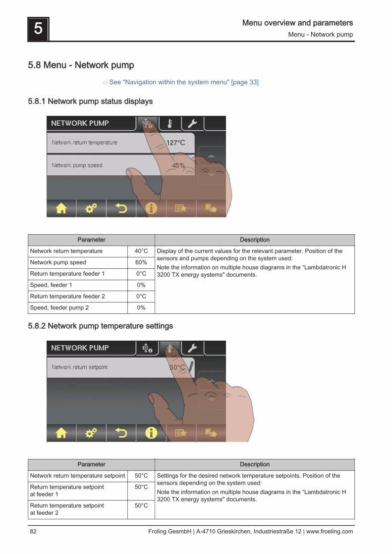
5.8 Menu - Network pump
⇨ See "Navigation within the system menu" [page 33]
5.8.1 Network pump status displays
Parameter Description
Network return temperature 40°C Display of the current values for the relevant parameter. Position of thesensors and pumps depending on the system used:Note the information on multiple house diagrams in the “Lambdatronic H3200 TX energy systems" documents.
Network pump speed 60%
Return temperature feeder 1 0°C
Speed, feeder 1 0%
Return temperature feeder 2 0°C
Speed, feeder pump 2 0%
5.8.2 Network pump temperature settings
Parameter Description
Network return temperature setpoint 50°C Settings for the desired network temperature setpoints. Position of thesensors depending on the system used:Note the information on multiple house diagrams in the “Lambdatronic H3200 TX energy systems" documents.
Return temperature setpoint at feeder 1
50°C
Return temperature setpointat feeder 2
50°C
5 Menu overview and parametersMenu - Network pump
82 Froling GesmbH | A-4710 Grieskirchen, Industriestraße 12 | www.froeling.com
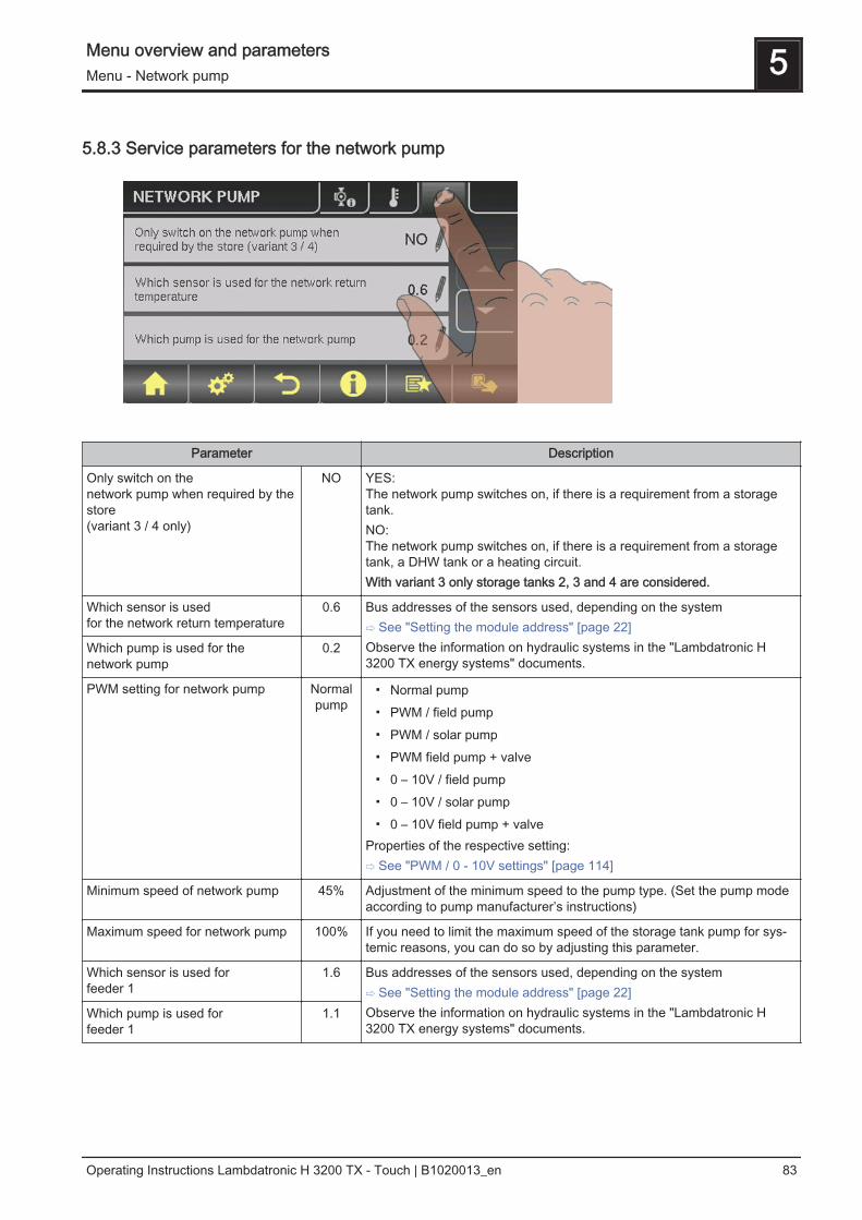
5.8.3 Service parameters for the network pump
Parameter Description
Only switch on the network pump when required by thestore(variant 3 / 4 only)
NO YES:The network pump switches on, if there is a requirement from a storagetank.NO:The network pump switches on, if there is a requirement from a storagetank, a DHW tank or a heating circuit.With variant 3 only storage tanks 2, 3 and 4 are considered.
Which sensor is used for the network return temperature
0.6 Bus addresses of the sensors used, depending on the system⇨ See "Setting the module address" [page 22]Observe the information on hydraulic systems in the "Lambdatronic H3200 TX energy systems" documents.
Which pump is used for the network pump
0.2
PWM setting for network pump Normalpump
▪ Normal pump▪ PWM / field pump▪ PWM / solar pump▪ PWM field pump + valve▪ 0 – 10V / field pump▪ 0 – 10V / solar pump▪ 0 – 10V field pump + valve
Properties of the respective setting:⇨ See "PWM / 0 - 10V settings" [page 114]
Minimum speed of network pump 45% Adjustment of the minimum speed to the pump type. (Set the pump modeaccording to pump manufacturer’s instructions)
Maximum speed for network pump 100% If you need to limit the maximum speed of the storage tank pump for sys‐temic reasons, you can do so by adjusting this parameter.
Which sensor is used for feeder 1
1.6 Bus addresses of the sensors used, depending on the system⇨ See "Setting the module address" [page 22]Observe the information on hydraulic systems in the "Lambdatronic H3200 TX energy systems" documents.
Which pump is used for feeder 1
1.1
Menu overview and parameters 5Menu - Network pump
Operating Instructions Lambdatronic H 3200 TX - Touch | B1020013_en 83

Parameter Description
PWM setting for feeder pump 1 Normalpump
▪ Normal pump▪ PWM / field pump▪ PWM / solar pump▪ PWM field pump + valve▪ 0 – 10V / field pump▪ 0 – 10V / solar pump▪ 0 – 10V field pump + valve
Properties of the respective setting:⇨ See "PWM / 0 - 10V settings" [page 114]
Minimum speed for feeder pump 1 45% Adjustment of the minimum speed to the pump type. (Set the pump modeaccording to pump manufacturer’s instructions)
Maximum speed for feeder pump 1 100% If you need to limit the maximum speed of the storage tank pump for sys‐temic reasons, you can do so by adjusting this parameter.
5 Menu overview and parametersMenu - Cascade
84 Froling GesmbH | A-4710 Grieskirchen, Industriestraße 12 | www.froeling.com

5.9 Menu - Cascade
⇨ See "Navigation within the system menu" [page 33]
5.9.1 Status displays for the cascade
Parameter Description
Store charge 0% Displays the current values for the relevant parameter.:Backup boiler 1
Backup boiler 2
Backup boiler 3
5.9.2 Status display of the cascade backup boiler
Parameter Description
Backup boiler boiler temperature 40°C Displays the current values for the relevant parameter.:Backup boiler OK 1
Backup boiler is heating 1
Backup boiler control variable 96%
Boiler charging pump speed 45%
Menu overview and parameters 5Menu - Cascade
Operating Instructions Lambdatronic H 3200 TX - Touch | B1020013_en 85
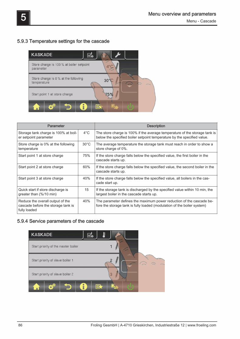
5.9.3 Temperature settings for the cascade
Parameter Description
Storage tank charge is 100% at boil‐er setpoint parameter
4°C The store charge is 100% if the average temperature of the storage tank isbelow the specified boiler setpoint temperature by the specified value.
Store charge is 0% at the followingtemperature
30°C The average temperature the storage tank must reach in order to show astore charge of 0%.
Start point 1 at store charge 75% If the store charge falls below the specified value, the first boiler in thecascade starts up.
Start point 2 at store charge 60% If the store charge falls below the specified value, the second boiler in thecascade starts up.
Start point 3 at store charge 40% If the store charge falls below the specified value, all boilers in the cas‐cade start up.
Quick start if store discharge isgreater than (%/10 min)
15 If the storage tank is discharged by the specified value within 10 min, thelargest boiler in the cascade starts up.
Reduce the overall output of thecascade before the storage tank isfully loaded
40% The parameter defines the maximum power reduction of the cascade be‐fore the storage tank is fully loaded (modulation of the boiler system)
5.9.4 Service parameters of the cascade
5 Menu overview and parametersMenu - Cascade
86 Froling GesmbH | A-4710 Grieskirchen, Industriestraße 12 | www.froeling.com
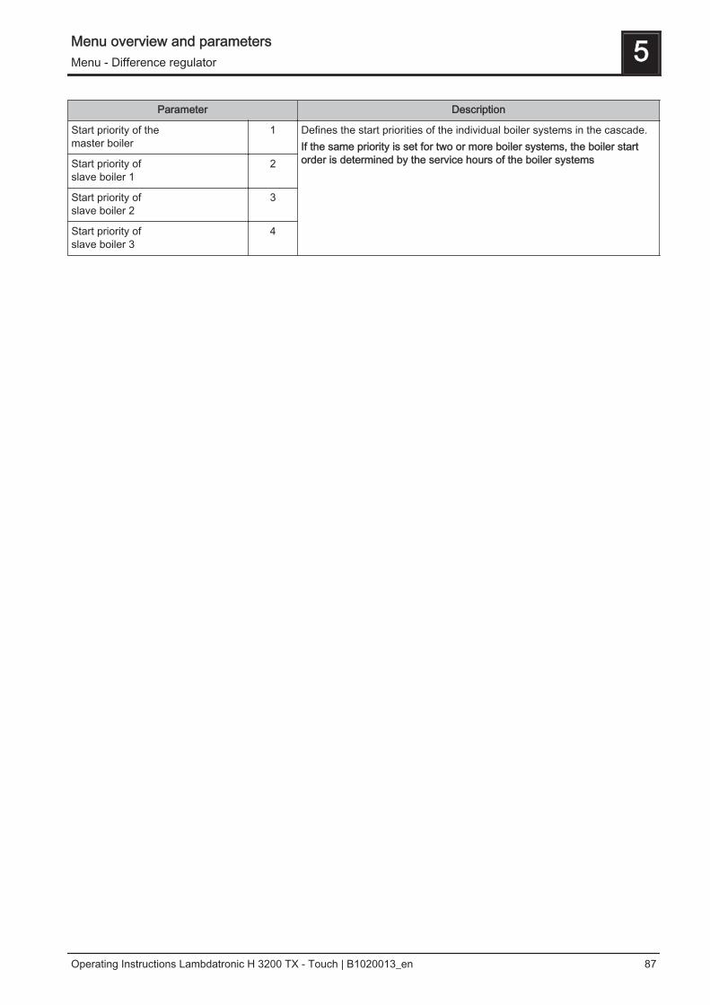
Parameter Description
Start priority of themaster boiler
1 Defines the start priorities of the individual boiler systems in the cascade.If the same priority is set for two or more boiler systems, the boiler startorder is determined by the service hours of the boiler systemsStart priority of
slave boiler 12
Start priority ofslave boiler 2
3
Start priority ofslave boiler 3
4
Menu overview and parameters 5Menu - Difference regulator
Operating Instructions Lambdatronic H 3200 TX - Touch | B1020013_en 87
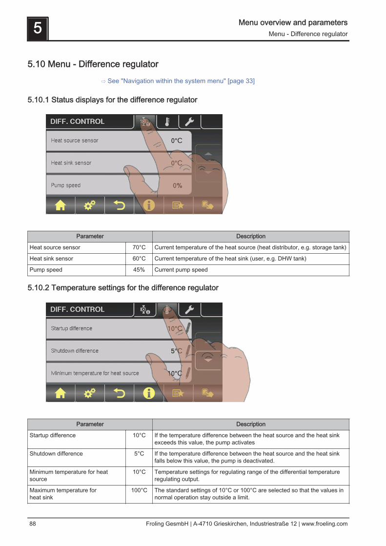
5.10 Menu - Difference regulator
⇨ See "Navigation within the system menu" [page 33]
5.10.1 Status displays for the difference regulator
Parameter Description
Heat source sensor 70°C Current temperature of the heat source (heat distributor, e.g. storage tank)
Heat sink sensor 60°C Current temperature of the heat sink (user, e.g. DHW tank)
Pump speed 45% Current pump speed
5.10.2 Temperature settings for the difference regulator
Parameter Description
Startup difference 10°C If the temperature difference between the heat source and the heat sinkexceeds this value, the pump activates
Shutdown difference 5°C If the temperature difference between the heat source and the heat sinkfalls below this value, the pump is deactivated.
Minimum temperature for heatsource
10°C Temperature settings for regulating range of the differential temperatureregulating output.
Maximum temperature for heat sink
100°C The standard settings of 10°C or 100°C are selected so that the values innormal operation stay outside a limit.
5 Menu overview and parametersMenu - Difference regulator
88 Froling GesmbH | A-4710 Grieskirchen, Industriestraße 12 | www.froeling.com
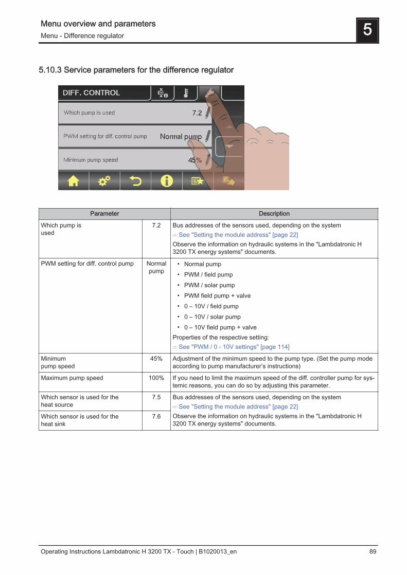
5.10.3 Service parameters for the difference regulator
Parameter Description
Which pump is used
7.2 Bus addresses of the sensors used, depending on the system⇨ See "Setting the module address" [page 22]Observe the information on hydraulic systems in the "Lambdatronic H3200 TX energy systems" documents.
PWM setting for diff. control pump Normalpump
▪ Normal pump▪ PWM / field pump▪ PWM / solar pump▪ PWM field pump + valve▪ 0 – 10V / field pump▪ 0 – 10V / solar pump▪ 0 – 10V field pump + valve
Properties of the respective setting:⇨ See "PWM / 0 - 10V settings" [page 114]
Minimum pump speed
45% Adjustment of the minimum speed to the pump type. (Set the pump modeaccording to pump manufacturer’s instructions)
Maximum pump speed 100% If you need to limit the maximum speed of the diff. controller pump for sys‐temic reasons, you can do so by adjusting this parameter.
Which sensor is used for the heat source
7.5 Bus addresses of the sensors used, depending on the system⇨ See "Setting the module address" [page 22]Observe the information on hydraulic systems in the "Lambdatronic H3200 TX energy systems" documents.
Which sensor is used for the heat sink
7.6
Menu overview and parameters 5Menu - Difference regulator
Operating Instructions Lambdatronic H 3200 TX - Touch | B1020013_en 89

5.11 Menu - Circulation pump
⇨ See "Navigation within the system menu" [page 33]
5.11.1 Status displays for the circulation pump
Parameter Description
Return temperature in circulation line
45°C Shows the current temperature at the return sensor of the circulation line.If the parameter "Return sensor present" is set to "NO", 0°C is permanent‐ly displayed.
Flow switch on the domestic hot water line
1 Shows the current status of the flow sensor.0 ... No flow at the valve1 ... Valve registers flow
Speed of the circulation pump
100% Current circulation pump speed
5.11.2 Temperature settings for the circulation pump
5 Menu overview and parametersMenu - Circulation pump
90 Froling GesmbH | A-4710 Grieskirchen, Industriestraße 12 | www.froeling.com

Parameter Description
Is a return sensor (present)? YES YES:The circulation pump is controlled according to time program and temper‐ature at the sensor. In conjunction with the use of a flow valve, the circula‐tion pump is also activated at a signal from the flow valve.NO:The circulation pump is controlled according to time program. In conjunc‐tion with the use of a flow valve, the circulation pump is also activated at asignal from the flow valve.Connect the flow sensor as the return sensor!
Switch off the pump at what returntemperature in the circulation line
50°C Parameter only relevant when a return sensor is used!If the set temperature is reached, the circulation pump shuts down.
Circulation pump run-on 300s Parameter only when a flow valve is used!If the flow valve does not register any more flow, the circulation pump car‐ries on running for the time set.
5.11.3 Time settings for the circulation pump
⇨ See "Setting times" [page 36]
5.11.4 Service parameters of the circulation pump
Menu overview and parameters 5Menu - Circulation pump
Operating Instructions Lambdatronic H 3200 TX - Touch | B1020013_en 91

Parameter Description
Which sensor is used for the circulation return
0.6 Bus addresses of the sensors and pumps used, depending on the system⇨ See "Setting the module address" [page 22]Observe the information on hydraulic systems in the "Lambdatronic H3200 TX energy systems" documents.
Which sensor input is used for theflow switch
1.5
Which pump is used for the circula‐tion
3.1
PWM settings for the circulationpump
Normalpump
▪ Normal pump▪ PWM / field pump▪ PWM / solar pump▪ PWM field pump + valve▪ 0 – 10V / field pump▪ 0 – 10V / solar pump▪ 0 – 10V field pump + valve
Properties of the respective setting:⇨ See "PWM / 0 - 10V settings" [page 114]
Minimum speed of the circulationpump
45% Adjustment of the minimum speed to the pump type. (Set the pump modeaccording to pump manufacturer’s instructions)
Maximum speed of the circulationpump
100% If you need to limit the maximum speed of the circulation pump for system‐ic reasons, you can do so by adjusting this parameter.
5 Menu overview and parametersMenu - Manual
92 Froling GesmbH | A-4710 Grieskirchen, Industriestraße 12 | www.froeling.com
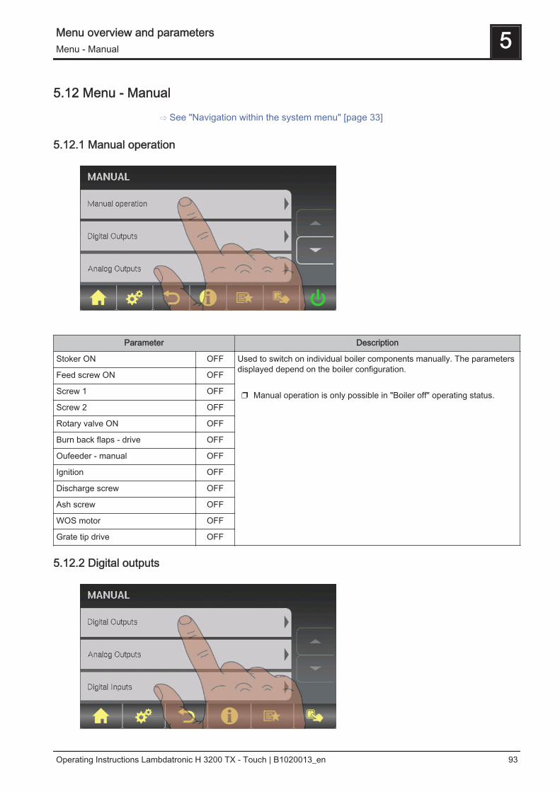
5.12 Menu - Manual
⇨ See "Navigation within the system menu" [page 33]
5.12.1 Manual operation
Parameter Description
Stoker ON OFF Used to switch on individual boiler components manually. The parametersdisplayed depend on the boiler configuration. ❒ Manual operation is only possible in "Boiler off" operating status.
Feed screw ON OFF
Screw 1 OFF
Screw 2 OFF
Rotary valve ON OFF
Burn back flaps - drive OFF
Oufeeder - manual OFF
Ignition OFF
Discharge screw OFF
Ash screw OFF
WOS motor OFF
Grate tip drive OFF
5.12.2 Digital outputs
Menu overview and parameters 5Menu - Manual
Operating Instructions Lambdatronic H 3200 TX - Touch | B1020013_en 93

Parameter Description
Lambda probe heating A 0 Used to test the digital outputs and is intended only for service techni‐cians. The parameters displayed vary depending on the configurationA … automatic-A 0 ... Automatic, OFF-A 1 … automatic, ON 0 … MANUAL, OFF1 … MANUAL, ON
Burner relays A 0
Standby relay A 0
Common fault relay A 0
Ignition A 0
WOS motor A 0
Ash screw A 0
BBF motor A 0
Return feed mixer OPEN A 0
Return feed mixer CLOSED A 0
Grate tip drive A 0
Stoker forwards A 0
Stoker backwards A 0
Screw 1 Forward A 0
Screw 1 Back A 0
Screw 2 Forward A 0
Screw 2 Back A 0
Feed screw forward A 0
Feed screw backwards A 0
Rotary valve forward A 0
Rotary valve back A 0
Discharge screw forward A 0
Discharge screw back A 0
5.12.3 Analogue outputs
5 Menu overview and parametersMenu - Manual
94 Froling GesmbH | A-4710 Grieskirchen, Industriestraße 12 | www.froeling.com

Parameter Description
Primary air Actualvalue:20%
A 18%
Used to test the analogue outputs and is intended only for service techni‐cians. The parameters displayed vary depending on the configuration A … automatic-A 0% … automatic, OFF-A 1% - 100% … automatic, with % value ON 0% … manual, OFF1% - 100% ... manual, with corresponding % value ON
Secondary air Actualvalue:
5%A 5%
ID Fan Actualvalue: 0
rpmA 0%
Combustion air blower fan A 0%
Pump 1 on core module A 0%
Pump 0.1 A 0%
Pump 0.2 A 0%
::
Pump 7.1 A 0%
Pump 7.2 A 0%
5.12.4 Digital inputs
Parameter Description
Door switch A 0 Used to test the digital inputs and intended only for service technicians.The parameters displayed vary depending on the configuration. A … automatic -A 0 … automatic, OFF-A 1 … automatic, ON 0 ... manual, OFF1 ... manual, ON
Hi-limit stat input A 0
E-stop input A 0
Boiler enable A 0
Light barrier in gravity shaft free A 0
Tipping grate closed A 1
Rotation protection switch OK A 1
Reserve input to TMM A 0
Menu overview and parameters 5Menu - Manual
Operating Instructions Lambdatronic H 3200 TX - Touch | B1020013_en 95
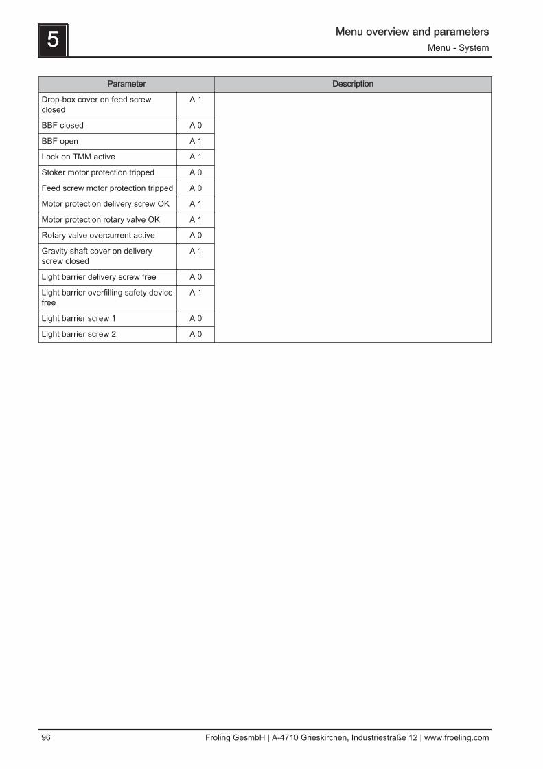
Parameter Description
Drop-box cover on feed screwclosed
A 1
BBF closed A 0
BBF open A 1
Lock on TMM active A 1
Stoker motor protection tripped A 0
Feed screw motor protection tripped A 0
Motor protection delivery screw OK A 1
Motor protection rotary valve OK A 1
Rotary valve overcurrent active A 0
Gravity shaft cover on deliveryscrew closed
A 1
Light barrier delivery screw free A 0
Light barrier overfilling safety devicefree
A 1
Light barrier screw 1 A 0
Light barrier screw 2 A 0
5 Menu overview and parametersMenu - System
96 Froling GesmbH | A-4710 Grieskirchen, Industriestraße 12 | www.froeling.com
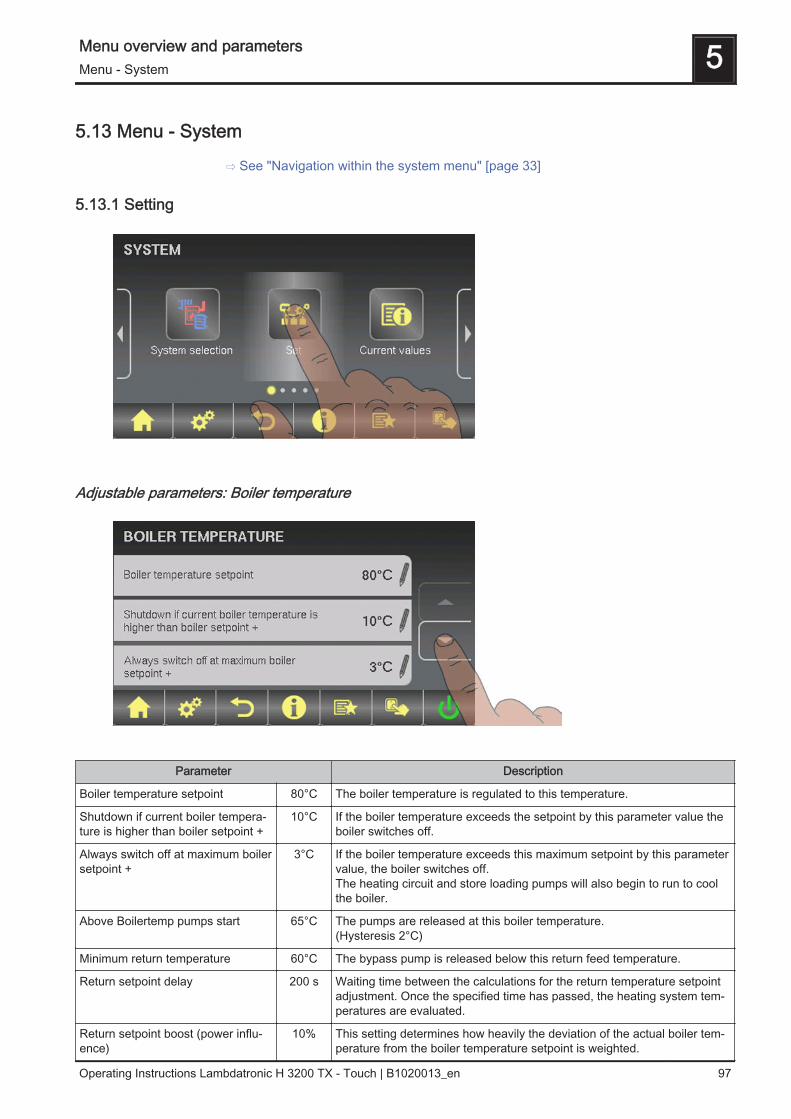
5.13 Menu - System
⇨ See "Navigation within the system menu" [page 33]
5.13.1 Setting
Adjustable parameters: Boiler temperature
Parameter Description
Boiler temperature setpoint 80°C The boiler temperature is regulated to this temperature.
Shutdown if current boiler tempera‐ture is higher than boiler setpoint +
10°C If the boiler temperature exceeds the setpoint by this parameter value theboiler switches off.
Always switch off at maximum boilersetpoint +
3°C If the boiler temperature exceeds this maximum setpoint by this parametervalue, the boiler switches off.The heating circuit and store loading pumps will also begin to run to coolthe boiler.
Above Boilertemp pumps start 65°C The pumps are released at this boiler temperature.(Hysteresis 2°C)
Minimum return temperature 60°C The bypass pump is released below this return feed temperature.
Return setpoint delay 200 s Waiting time between the calculations for the return temperature setpointadjustment. Once the specified time has passed, the heating system tem‐peratures are evaluated.
Return setpoint boost (power influ‐ence)
10% This setting determines how heavily the deviation of the actual boiler tem‐perature from the boiler temperature setpoint is weighted.
Menu overview and parameters 5Menu - System
Operating Instructions Lambdatronic H 3200 TX - Touch | B1020013_en 97

Parameter Description
Return feed lift min. dif. at min. out‐put
10% Minimum difference between boiler setpoint and return setpoint. The boilertemperature difference should not fall below this value. (Setting applies topartial load)
Return feed lift min. dif. at 100%output
20% Minimum difference between boiler setpoint and return setpoint. The boilertemperature difference should not fall below this value. (Setting applies topartial load)An interpolation is made between the two settings between partial andnominal load.
Heating circuit overheat in variablemode
2°C If variable mode is activated, the boiler setpoint temperature in heatingmode is increased by this value compared to the required flow tempera‐ture.
Adjustable Parameters: Flue Gas
Parameter Description
Minimum flue gas temperature 95°C Min. setpoint for the flue gas temperature. Lowest load point for continu‐ous operation
Max. flue gas temperature 160°C Max. setpoint for the flue gas temperature. Highest load point for suffi‐ciently good degree of efficiency.
Boiler output at flue gas tempera‐ture of 20°C
35% Start ramp of boiler regulator at system startup. Lower point of the startramp (factory setting)
100% boiler output from a flue gastemperature of
100°C Start ramp of boiler regulator at system startup. If the flue gas temperatureis above the specified setpoint, fuel output should reach 100% (upperpoint of the start ramp)
Minimum difference between fluegas temperature and boiler temper‐ature in HEATING
10°C Criterion for "safety time".
Flue gas - Flue gas difference forstart process
7°C Criterion for flame recognition.
Safety time 18 m Time for which the boiler attempts to maintain a flame.
Flue gas temperature, below whichboiler switches to SHUTDOWN sta‐tus
90°C Below this temperature no flame is present in the combustion chamber.
5 Menu overview and parametersMenu - System
98 Froling GesmbH | A-4710 Grieskirchen, Industriestraße 12 | www.froeling.com

Adjustable Parameters: Air settings
Parameter Description
Maximum ID fan speed 80% Adjusting the minimum speed of the fan used
Minimum fan speed of combustionchamber controller
100%
Primary air opening at 0% signal 24% How far should the primary air be open already at 0% control.
Primary air opening at 100% signal 30% What is the maximum distance the primary air can open at 100% signal?
Secondary air opening at 0% signal 2% How far should the secondary air already be open at 0% signal?
Secondary air opening at 100% sig‐nal
80% What is the maximum distance the secondary air can open at 100% sig‐nal?
Primary air delay 30s How long is a switch in primary air control delayed?
Primary air boost during heating up 25% Primary air boost in percent above the regulated value for the duration ofthe primary air boost.
Duration of primary air boost 4m How long is the primary air boost effective?
Primary air boost during shutdown 50% Primary air boost in percent above the regulated value in "Empty stoker"operating status.
ID fan startup time 90 s Time that the ID fan needs to accelerate from 0% to 100% speed.
Adjustable parameters: Fuel feed
Menu overview and parameters 5Menu - System
Operating Instructions Lambdatronic H 3200 TX - Touch | B1020013_en 99

Parameters Description
Maximum loading rate 35% Loading rate at maximum boiler output.
Minimum loading rate 25% Minimum feed rate of stoker screw
Stoker pre-run 2.0 s Time that the stoker runs before the feed screw is activated.
Feed time of feed screw is 5.0 s Time feed screw is on until stoker screw
The time until the stoker is full is 87s Total time that the feed screw is on until the fuel falls onto the grate.
The time until the stoker is empty is 136s Theoretical runtime of the feed screw until there is no more fuel in thestoker.
Rotary valve run-on 2.0 s Time that the rotary valve continues to run after the feed screw has stop‐ped (only for directly driven rotary valve!)
Switch-on delay of light barrier ingravity shaft
2.0 s The time for which the light barrier must consistently recognise material toactivate material recognition in the gravity shaft.
Switch-off delay of light barrier ingravity shaft
2.0 s The time for which the light barrier must consistently recognise no materi‐al to de-activate material recognition in the gravity shaft.
Switch-off delay of delivery screw(s)light barrier(s)
2.0 s The time for which the light barrier must consistently recognise material toactivate material recognition in the delivery screw.
Switch-on delay of delivery screw(s)light barrier(s)
2.0 s The time for which the light barrier must consistently recognise no materi‐al to deactivate material recognition in the delivery screw.
Error of light barrier(s) is delayed for 90 s Time delay until an error in the material recognition is tripped.
Counter limit for troubleshooting ofrotary valve overcurrent is
3 How many troubleshooting attempts should be carried out if the overcur‐rent sensor of the rotary valve activates.
During troubleshooting of feedscrew, it turns forwards for
1.5 s How long should the screw turn forwards during troubleshooting.
During troubleshooting of feedscrew, it turns backwards for
1.5 s How long should the screw turn backwards during troubleshooting.
During troubleshooting of rotaryvalve, it turns forwards for
1.5 s How long should the rotary valve turn forwards during troubleshooting.
During troubleshooting of rotaryvalve, it turns backwards for
1.5 s How long should the rotary valve turn backwards during troubleshooting.
A rotary valve motor protectionswitch error is delayed for
2 s How long should the motor protection error be delayed.
The back-burn flap opens after amaximum of
150 s Time until the burn back flap has turned from the closed to the open posi‐tion.
The back-burn flap closes after amaximum of
50 s Time until the burn back flap has turned from the open to the closed posi‐tion.
Nominal current for stoker screw 0.80 A Nominal current for the stoker screw motor according to the identificationplate on the motor.
Nominal current for discharge screw 1.10 A Nominal current for the discharge screw motor according to the identifica‐tion plate on the motor.
Nominal current for rotary valve 1.10 A Nominal current for the rotary valve motor according to the identificationplate on the motor.
Min. current monitoring with stoker /delivery screw
YES Detects failure of measured phase.
5 Menu overview and parametersMenu - System
100 Froling GesmbH | A-4710 Grieskirchen, Industriestraße 12 | www.froeling.com
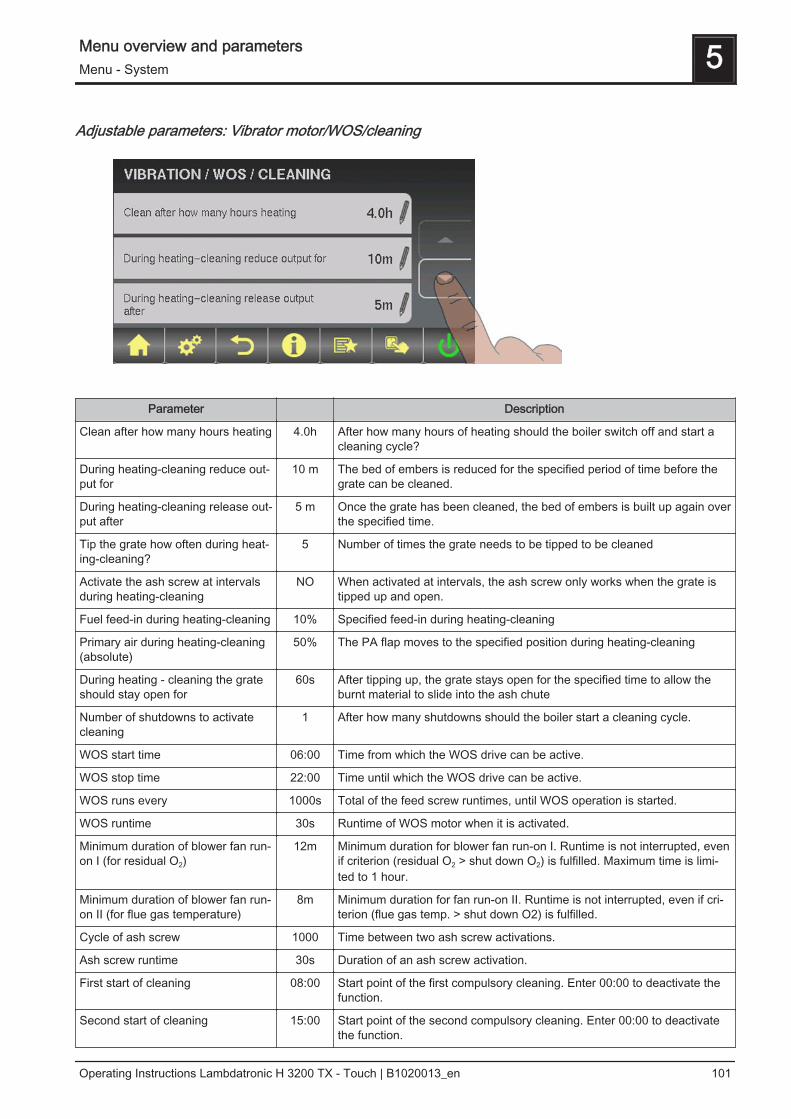
Adjustable parameters: Vibrator motor/WOS/cleaning
Parameter Description
Clean after how many hours heating 4.0h After how many hours of heating should the boiler switch off and start acleaning cycle?
During heating-cleaning reduce out‐put for
10 m The bed of embers is reduced for the specified period of time before thegrate can be cleaned.
During heating-cleaning release out‐put after
5 m Once the grate has been cleaned, the bed of embers is built up again overthe specified time.
Tip the grate how often during heat‐ing-cleaning?
5 Number of times the grate needs to be tipped to be cleaned
Activate the ash screw at intervalsduring heating-cleaning
NO When activated at intervals, the ash screw only works when the grate istipped up and open.
Fuel feed-in during heating-cleaning 10% Specified feed-in during heating-cleaning
Primary air during heating-cleaning(absolute)
50% The PA flap moves to the specified position during heating-cleaning
During heating - cleaning the grateshould stay open for
60s After tipping up, the grate stays open for the specified time to allow theburnt material to slide into the ash chute
Number of shutdowns to activatecleaning
1 After how many shutdowns should the boiler start a cleaning cycle.
WOS start time 06:00 Time from which the WOS drive can be active.
WOS stop time 22:00 Time until which the WOS drive can be active.
WOS runs every 1000s Total of the feed screw runtimes, until WOS operation is started.
WOS runtime 30s Runtime of WOS motor when it is activated.
Minimum duration of blower fan run-on I (for residual O2)
12m Minimum duration for blower fan run-on I. Runtime is not interrupted, evenif criterion (residual O2 > shut down O2) is fulfilled. Maximum time is limi‐ted to 1 hour.
Minimum duration of blower fan run-on II (for flue gas temperature)
8m Minimum duration for fan run-on II. Runtime is not interrupted, even if cri‐terion (flue gas temp. > shut down O2) is fulfilled.
Cycle of ash screw 1000 Time between two ash screw activations.
Ash screw runtime 30s Duration of an ash screw activation.
First start of cleaning 08:00 Start point of the first compulsory cleaning. Enter 00:00 to deactivate thefunction.
Second start of cleaning 15:00 Start point of the second compulsory cleaning. Enter 00:00 to deactivatethe function.
Menu overview and parameters 5Menu - System
Operating Instructions Lambdatronic H 3200 TX - Touch | B1020013_en 101
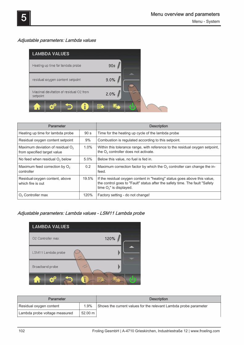
Adjustable parameters: Lambda values
Parameter Description
Heating up time for lambda probe 90 s Time for the heating up cycle of the lambda probe
Residual oxygen content setpoint 9% Combustion is regulated according to this setpoint.
Maximum deviation of residual O2
from specified target value1.0% Within this tolerance range, with reference to the residual oxygen setpoint,
the O2 controller does not activate.
No feed when residual O2 below 5.0% Below this value, no fuel is fed in.
Maximum feed correction by O2
controller0.2 Maximum correction factor by which the O2 controller can change the in‐
feed.
Residual oxygen content, abovewhich fire is out
19.5% If the residual oxygen content in "heating" status goes above this value,the control goes to "Fault" status after the safety time. The fault "Safetytime O2" is displayed.
O2 Controller max 120% Factory setting - do not change!
Adjustable parameters: Lambda values - LSM11 Lambda probe
Parameter Description
Residual oxygen content 1.9% Shows the current values for the relevant Lambda probe parameter Lambda probe voltage measured 52.00 m
5 Menu overview and parametersMenu - System
102 Froling GesmbH | A-4710 Grieskirchen, Industriestraße 12 | www.froeling.com

Parameter Description
Lambda probes correction value 0.0
Lambda probe voltage corrected 52.00 m
Adjustable parameters – Lambda values – Broadband probe
Parameter Description
Residual oxygen content 1.9% Displays the current value
Broadband probe types(1…BOSCH / 2…NTK)(3…LSM11 input)
1 Defines the probe type used
Broadband probe calibration(probe must be at 21% O2)
NO After activation of the lambda probe heating, the lambda probe can becalibrated using this value.CAUTION: The probe must be at 21% O2 (air).
Broadband probe heating current 0.00A Display of the current values for the relevant broadband probe parameter
Broadband probe heating voltage 0.00V
Broadband probe Nernstvoltage
0.000V
Broadband probe pump current 0.000m
Broadband probe internal resistance 0R
Menu overview and parameters 5Menu - System
Operating Instructions Lambdatronic H 3200 TX - Touch | B1020013_en 103
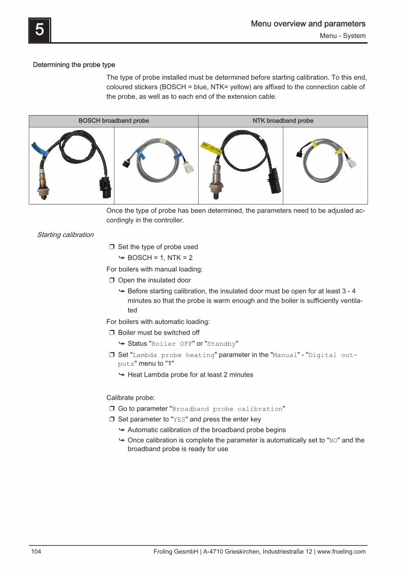
Determining the probe type
The type of probe installed must be determined before starting calibration. To this end,coloured stickers (BOSCH = blue, NTK= yellow) are affixed to the connection cable ofthe probe, as well as to each end of the extension cable.
BOSCH broadband probe NTK broadband probe
Once the type of probe has been determined, the parameters need to be adjusted ac‐cordingly in the controller.
Starting calibration❒ Set the type of probe used
➥ BOSCH = 1, NTK = 2For boilers with manual loading:❒ Open the insulated door
➥ Before starting calibration, the insulated door must be open for at least 3 - 4minutes so that the probe is warm enough and the boiler is sufficiently ventila‐ted
For boilers with automatic loading:❒ Boiler must be switched off
➥ Status "Boiler OFF" or "Standby"❒ Set "Lambda probe heating" parameter in the "Manual" - "Digital out-
puts" menu to "1"➥ Heat Lambda probe for at least 2 minutes
Calibrate probe:❒ Go to parameter "Broadband probe calibration"❒ Set parameter to "YES" and press the enter key
➥ Automatic calibration of the broadband probe begins➥ Once calibration is complete the parameter is automatically set to "NO" and the
broadband probe is ready for use
5 Menu overview and parametersMenu - System
104 Froling GesmbH | A-4710 Grieskirchen, Industriestraße 12 | www.froeling.com

Adjustable parameters: General settings
Parameter Description
Modem installed NO If the boiler has a modem for data transfer, this value must be set to"YES".
Memory cycle of data logger 5 s Do not change this value!This is the memory cycle used for saving data onto the data logger.
Output warnings through fault message relays
NO If this parameter is set to "YES", warnings from the boiler system are alsodisplayed on the fault message relay.
Send a line break when ASCII dataoutput on COM2
NO
COM 2 is used as a MODBUS interface
NO YES:The COM 2 interface can be used for connection with a MODBUS (RTU /ASCII)NO:The COM 2 interface sends the most important boiler values every second
MODBUS address 2 Adjustable parameters for MODBUS
MODBUS protocol(1 – RTU / 2 – ASCII)
1
5.13.2 Current values
Menu overview and parameters 5Menu - System
Operating Instructions Lambdatronic H 3200 TX - Touch | B1020013_en 105

Parameter Description
Current status runtime 0 s Length of time in current operating status.
Maximum status runtime 0 s Maximum length of time in current operating status. At the end of this timeat the latest, the system switches to the next operating status. With oper‐ating statuses that have no specified length of time (e.g. heating), themaximum length of time is zero.
Boiler temperature 77°C Display of the current values for the relevant parameter:Flue gas temperature 195°C
Flue gas setpoint 198°C
Boiler control variable 95%
ID fan control 75%
ID fan speed 2230rpm
Combustion air blower fan 60%
Primary air 55%
Position of primary air flap 54%
Residual oxygen content 8.9%
Oxygen control 120%
Feed correction control 15%
Feed 30%
Secondary air 20%
Position of secondary air flap 19%
Calculated boiler setpoint 77°C
External temperature 3°C
Board temperature 29°C
Number of burner starts 60
Service hours 250 h
Software version:Version: 50.04Build: 05.07
Feed screw current 0.90A
Stoker screw current 0.85A
Comb. chamber under-pressure 35P
Return feed sensor 60°C
Combustion chamber temperature 635°C
Board temperature wood chip mod‐ule
28°C
Cust. no.: 2006544Boiler no.: 3125
System operator data
5 Menu overview and parametersMenu - System
106 Froling GesmbH | A-4710 Grieskirchen, Industriestraße 12 | www.froeling.com

Service hours
Parameter Description
Hours since last maintenance 26h Displays the current values for the relevant parameter.
Hours of heating 26h
Hours in partial load conditions(boiler control variable < 40%)
0h
Service hours of boiler 2 (burnercontact)
0h
Stoker screw service hours 0h
Feed screw service hours 0h
Ignition service hours 3h
Lambda probe service hours 30h
Opening/closing movements of thegrate
11
ID fan service hours 50h
Tipping drive load cycle 120
Heat exchanger service hours 2
Ash screw service hours 1h
Suction turbine(s) service hours 1h
Delivery screw service hours 3h
Menu overview and parameters 5Menu - System
Operating Instructions Lambdatronic H 3200 TX - Touch | B1020013_en 107
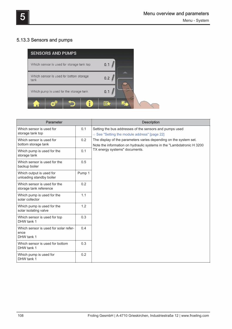
5.13.3 Sensors and pumps
Parameter Description
Which sensor is used for storage tank top
0.1 Setting the bus addresses of the sensors and pumps used⇨ See "Setting the module address" [page 22]The display of the parameters varies depending on the system set.Note the information on hydraulic systems in the "Lambdatronic H 3200TX energy systems" documents.
Which sensor is used for bottom storage tank
0.2
Which pump is used for the storage tank
0.1
Which sensor is used for the backup boiler
0.5
Which output is used for unloading standby boiler
Pump 1
Which sensor is used for the storage tank reference
0.2
Which pump is used for the solar collector
1.1
Which pump is used for the solar isolating valve
1.2
Which sensor is used for top DHW tank 1
0.3
Which sensor is used for solar refer‐ence DHW tank 1
0.4
Which sensor is used for bottom DHW tank 1
0.3
Which pump is used forDHW tank 1
0.2
5 Menu overview and parametersMenu - System
108 Froling GesmbH | A-4710 Grieskirchen, Industriestraße 12 | www.froeling.com

5.13.4 Display allocation
Parameter Description
ROOM SENSOR CORRECTION:
Deviation of room sensor from dis‐play with address 1
0°C If the current room temperature does not match the displayed/evaluatedvalue, this parameter can be used to adjust the evaluation of the roomtemperature sensor.:
Deviation of room sensor from dis‐play with address 7
0°C
HEATING SYSTEM:
Display with address 1 is allocated to the following heating circuit:
none Allocates the relevant control (address 1 - 7) to a particular heating circuit.WARNING! The parameters are set to "none" at the factory, so the heatingcircuit functions (room temperature sensor, party mode, setback mode, ...)are not possible on this control by default!:
Display with address 7 is allocated to the following heating circuit:
none
Touch display with address 1 is allo‐cated to the following heating circuit:
none
:
Touch display with address 7 is allo‐cated to the following heating circuit:
none
DHW TANK SYSTEM:
Display with address 1 is allocatedto the following DHW tank:
none Allocates the relevant control (address 1 - 7) to a particular DHW tank.WARNING! The parameters are set to "none" at the factory, so the hot wa‐ter functions (function key) are not possible on this control by default!
:
Display with address 7 is allocatedto the following DHW tank:
none
Touch display with address 1 is allo‐cated to the following DHW tank:
none
:
Touch display with address 7 is allo‐cated to the following DHW tank:
none
Menu overview and parameters 5Menu - System
Operating Instructions Lambdatronic H 3200 TX - Touch | B1020013_en 109
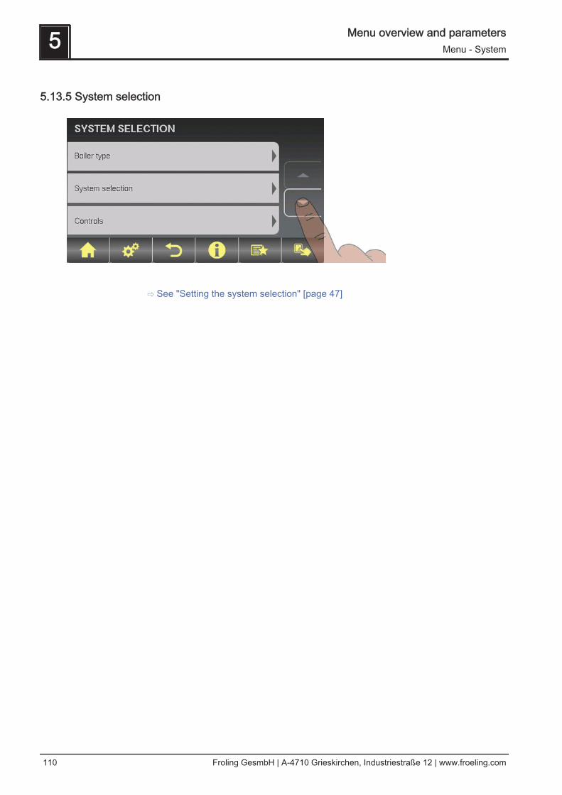
5.13.5 System selection
⇨ See "Setting the system selection" [page 47]
5 Menu overview and parametersMenu - System
110 Froling GesmbH | A-4710 Grieskirchen, Industriestraße 12 | www.froeling.com
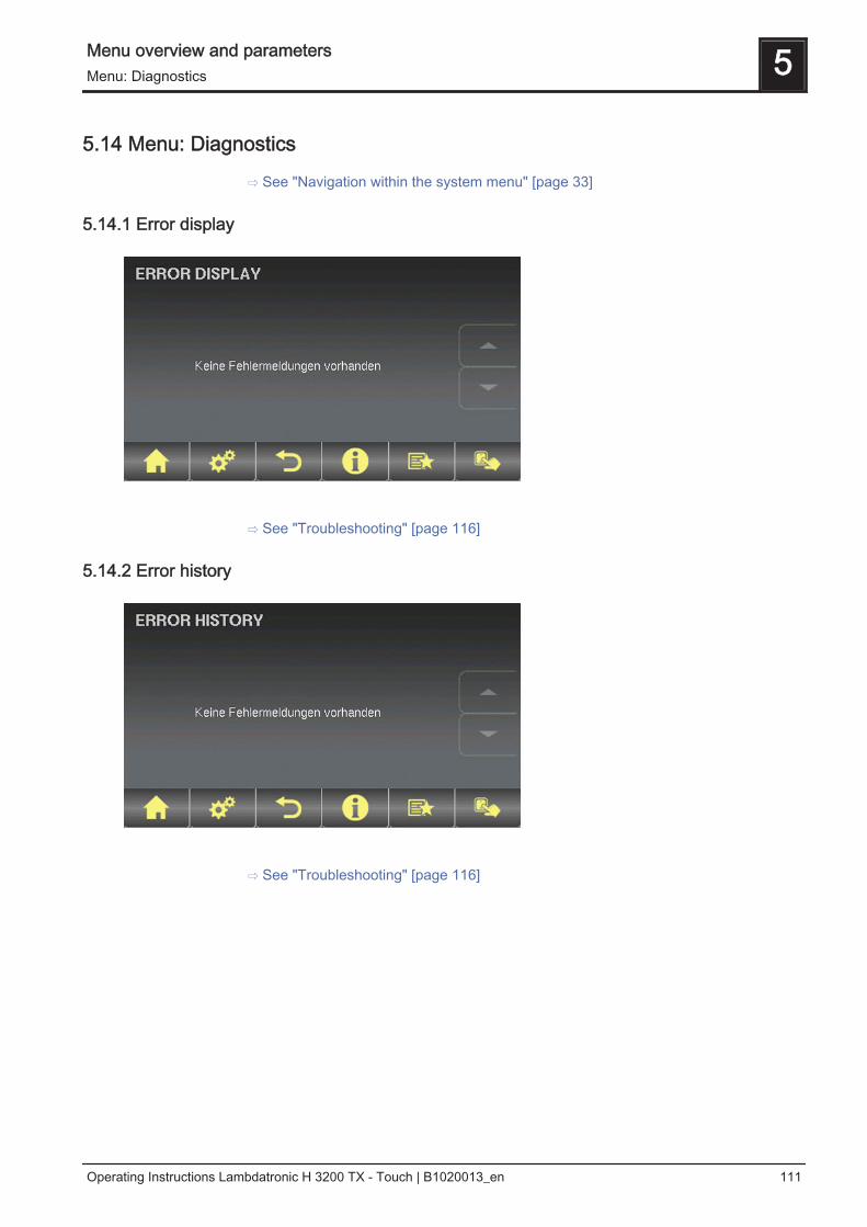
5.14 Menu: Diagnostics
⇨ See "Navigation within the system menu" [page 33]
5.14.1 Error display
⇨ See "Troubleshooting" [page 116]
5.14.2 Error history
⇨ See "Troubleshooting" [page 116]
Menu overview and parameters 5Menu: Diagnostics
Operating Instructions Lambdatronic H 3200 TX - Touch | B1020013_en 111
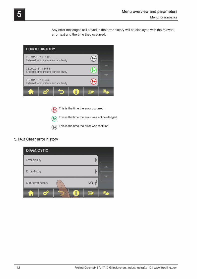
Any error messages still saved in the error history will be displayed with the relevanterror text and the time they occurred.
This is the time the error occurred.
This is the time the error was acknowledged.
This is the time the error was rectified.
5.14.3 Clear error history
5 Menu overview and parametersMenu: Diagnostics
112 Froling GesmbH | A-4710 Grieskirchen, Industriestraße 12 | www.froeling.com

5.15 Menu: Display settings
⇨ See "Navigation within the system menu" [page 33]
5.15.1 General
Parameter Description
Room temperature 26.0°C Shows the current room temperature
Room temperature sensor correc‐tion
0.0°C If the current room temperature does not match the displayed/evaluatedvalue, this parameter can be used to adjust the evaluation of the roomtemperature sensor.
Brightness 187.0 Light sensor’s evaluation of the current brightness in the room for adjust‐ing the backlight.
Maximum backlight 80% The brighter it is in the room, the more the background of the touch dis‐play is illuminated. This is where you can limit the maximum backlight.
Minimum backlight 20% The darker it is in the room, the less the background of the touch displayis illuminated. This is where you can set the minimum backlight.
Delay for screensaver (0 disablesthe screensaver)
60s If the screen of the touch display is not touched within the set time, thescreensaver will activate and the control will go dark. To disable thescreensaver, set the delay time to “0”.
Module address Address0
This is where you can change the module address if it is incorrectly set. Module address 0: Boiler consoleModule address 1-7: respective RBG TouchOnce you have changed the module address, you will need to restart theboiler controller (switch main switch on boiler off and on).
Menu overview and parameters 5Menu: Display settings
Operating Instructions Lambdatronic H 3200 TX - Touch | B1020013_en 113

5.15.2 Date / Time
⇨ See "Setting the date/time" [page 38]
5.15.3 Software update / Service
⇨ See "Updating the software of the touch control" [page 27]
5 Menu overview and parametersMenu: Display settings
114 Froling GesmbH | A-4710 Grieskirchen, Industriestraße 12 | www.froeling.com
5.16 PWM / 0 - 10V settings
Description
▪ Normal pump (3-stage)Set when a standard pump is run at the respective output. The pump is controlled at the 230V output using pulse pack‐ets.
▪ PWM / field pumpThere is a permanent power supply of 230V at the output for the high efficiency pump. The pump is controlled usingpulse duration modulation at the respective PWM output.
▪ PWM / Solar pumpHere again, the pump is controlled by means of pulse duration modulation at the respective PWM output. In this case,however, the characteristic line is inverted and can only be used for specially marked high efficiency solar pumps.
▪ PWM field pump+valveThe signal for the field pump is emitted at the PWM output. If the signal exceeds 2%, the 230V output is switched on. Ifthe signal is below 2% for more than 4 minutes, the output is switched off again.
▪ 0 – 10V / field pump▪ 0 – 10V / solar pump▪ 0 – 10V field pump+valve
The same functions that apply with PWM apply to the parameter values with 0-10V. The only difference is that insteadof pulse duration modulation, a 0-10V signal is used to control the pump.
Menu overview and parameters 5PWM / 0 - 10V settings
Operating Instructions Lambdatronic H 3200 TX - Touch | B1020013_en 115

6 TroubleshootingThe term "fault" is a collective term for warnings, errors and alarms. The boiler reactsdifferently to the three types of message:
WARNING In case of warnings the status LED flashes orange and the boiler initiallycontinues controlled operation.
ERROR When there is an error, the status LED flashes red, the boiler follows theshutdown procedure and remains in “Fault“ status until the problem is re‐solved.
ALARM An alarm triggers a system emergency stop. The status LED flashes red,the boiler switches off immediately and the heating circuit controller andpumps remain active.
A window with the corresponding fault text will also appear. Pressing the Cancel icontakes you back to the basic display. If the quick select icon and the warning triangleflash alternately, there is still a fault. The “Error display” button will now appear in thequick menu.
6.1 Procedure for fault messages
If you open the window with the respective fault text, the right arrow will take you topossible causes of the fault.
6 TroubleshootingProcedure for fault messages
116 Froling GesmbH | A-4710 Grieskirchen, Industriestraße 12 | www.froeling.com
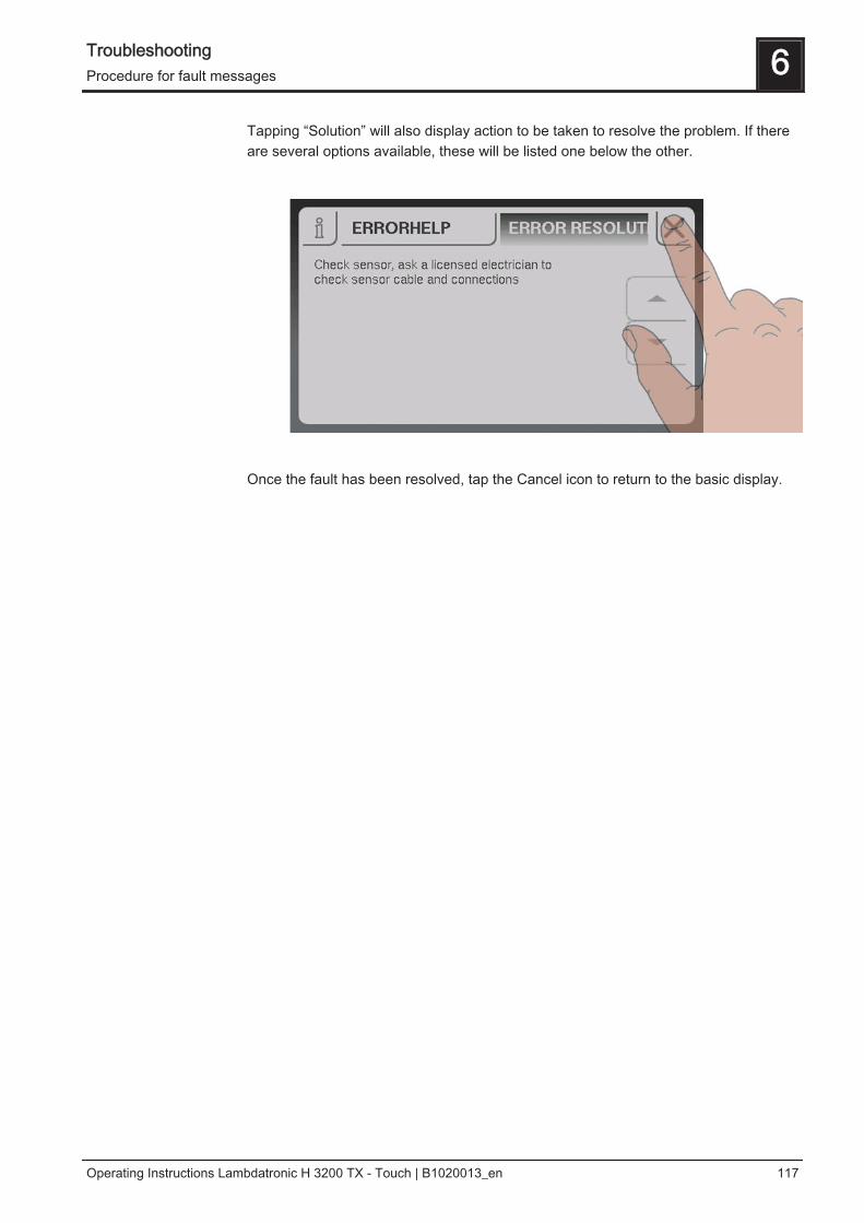
Tapping “Solution” will also display action to be taken to resolve the problem. If thereare several options available, these will be listed one below the other.
Once the fault has been resolved, tap the Cancel icon to return to the basic display.
Troubleshooting 6Procedure for fault messages
Operating Instructions Lambdatronic H 3200 TX - Touch | B1020013_en 117
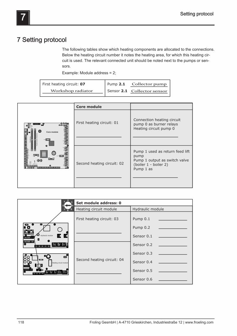
7 Setting protocolThe following tables show which heating components are allocated to the connections.Below the heating circuit number it notes the heating area, for which this heating cir‐cuit is used. The relevant connected unit should be noted next to the pumps or sen‐sors.Example: Module address = 2;
7 Setting protocol
118 Froling GesmbH | A-4710 Grieskirchen, Industriestraße 12 | www.froeling.com

Heating circuit module
Hydraulic module
Heating circuit module
Hydraulic module
Set module address: 2
First heating circuit: 07
Second heating circuit: 08
Heating circuit module Hydraulic module
Pump 2.1
Pump 2.2
Sensor 2.1
Sensor 2.2
Sensor 2.3
Sensor 2.4
Sensor 2.5
Sensor 2.6
Set modue address: 1
First heating circuit: 05
Second heating circuit: 06
Heating circuit module Hydraulic module
Pump 1.1
Pump 1.2
Sensor 1.1
Sensor 1.2
Sensor 1.3
Sensor 1.4
Sensor 1.5
Sensor 1.6
Final check
Bus cable correctly connected (see “Connecting the bus cable”))
Addressing correctly carried out and recorded
Jumper placed at the last module
Setting protocol 7
Operating Instructions Lambdatronic H 3200 TX - Touch | B1020013_en 119