boiler fundamentals
TRANSCRIPT

Presentation on Presentation on
Power Plant BoilerPower Plant Boiler
Boiler/ steam generatorBoiler/ steam generator
Steam generating device for a specific purpose.Steam generating device for a specific purpose.
Capable to meet variation in load demand Capable to meet variation in load demand
Capable of generating steam in a range of operating Capable of generating steam in a range of operating pressure and temperaturepressure and temperature
For utility purpose, it should generate steam For utility purpose, it should generate steam uninterruptedly at operating pressure and temperature uninterruptedly at operating pressure and temperature for running steam turbines.for running steam turbines.
Boiler/ steam generatorBoiler/ steam generator
Raw materials for Raw materials for design of boilersdesign of boilers
1.1. Coal from minesCoal from mines
2.2. Ambient air Ambient air
3.3. Water from natural Water from natural resources (river, resources (river, ponds)ponds)
o Generating heat Generating heat energyenergy
o Air for combustionAir for combustion
o Working fluid for Working fluid for steam generation, steam generation, possessing heat possessing heat energyenergy

Coal analysisCoal analysis
Typical composition (Proximate analysis)Typical composition (Proximate analysis)1. Fixed carbon1. Fixed carbon2. Fuel ash2. Fuel ash3. Volatile material3. Volatile material4. Total Moisture4. Total Moisture5. Sulfur5. Sulfur
o High calorific value/ Lower calorific value (Kcal/kg)High calorific value/ Lower calorific value (Kcal/kg)o Hardgrove Index (HGI)Hardgrove Index (HGI)
Coal analysisCoal analysis
Typical composition (Ultimate analysis)Typical composition (Ultimate analysis)1. Carbon1. Carbon2. Hydrogen2. Hydrogen3. Sulfur3. Sulfur4. Oxygen4. Oxygen5. Nitrogen5. Nitrogen6. Fuel Ash6. Fuel Ash
o Initial Deformation temperature (IDT)Initial Deformation temperature (IDT)o High calorific value/ Lower calorific value (Kcal/kg)High calorific value/ Lower calorific value (Kcal/kg)
Combustion of coalCombustion of coal
Carbon, hydrogen, sulfur are sources of heat on Carbon, hydrogen, sulfur are sources of heat on combustioncombustion
Surface moisture removed on heating during Surface moisture removed on heating during pulverization.pulverization.
Inherent moisture and volatiles are released at Inherent moisture and volatiles are released at higher temperature, making coal porous and higher temperature, making coal porous and leading to char/ coke formation. (Thermal leading to char/ coke formation. (Thermal preparation stage)preparation stage)
Fuel OilFuel Oil
Three liquid fuels used in power plantsThree liquid fuels used in power plants– 1. Heavy Fuel Oil (HFO)1. Heavy Fuel Oil (HFO)– 2. LSHS (Low Sulfur Heavy stock)2. LSHS (Low Sulfur Heavy stock)– 3. High speed Diesel (HSD)3. High speed Diesel (HSD)
Oil firing is preceded byOil firing is preceded by Lowering viscosity and increasing flowability on heating Lowering viscosity and increasing flowability on heating
for better combustion in given turn down ratio.(125for better combustion in given turn down ratio.(125ooC)C) Droplet formation on atomization (by steam/ Droplet formation on atomization (by steam/
compressed air/ mechanical pressurization) compressed air/ mechanical pressurization) Combustion initiation by High energy spark ignition Combustion initiation by High energy spark ignition
Combustion of reactantsCombustion of reactants
Reaction rate depends on concentration of one of the Reaction rate depends on concentration of one of the reactantsreactants
Concentration varies on partial pressure of the reactants.Concentration varies on partial pressure of the reactants.
Partial pressure is a function of gas temperature.Partial pressure is a function of gas temperature.
Therefore, reaction rate depends on temperature and Therefore, reaction rate depends on temperature and substance that enter the reaction.substance that enter the reaction.

Combustion of reactantsCombustion of reactants
Reaction rate [k] is expressed by Arrhenius law,Reaction rate [k] is expressed by Arrhenius law,
Where Where
kk00 = pre-exponential factor = pre-exponential factor
E =Activation energy (i.e. sufficient energy to destroy theE =Activation energy (i.e. sufficient energy to destroy the molecular bonds)molecular bonds)R= Gas constantR= Gas constantT= Absolute temperature of the processT= Absolute temperature of the process
RTEekk /0
Combustion Reactions (Carbon)Combustion Reactions (Carbon)
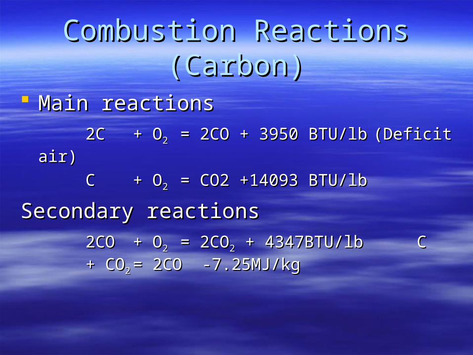
Main reactions Main reactions
2C2C + O+ O22 = 2CO + 3950 BTU/lb= 2CO + 3950 BTU/lb (Deficit air)(Deficit air)
CC + O+ O22 = CO2 +14093 BTU/lb= CO2 +14093 BTU/lb
Secondary reactionsSecondary reactions
2CO2CO + O+ O22 = 2CO= 2CO22 + 4347BTU/lb + 4347BTU/lb CC
+ CO+ CO22 = 2CO -7.25MJ/kg= 2CO -7.25MJ/kg

Combustion Reactions (Carbon)Combustion Reactions (Carbon)
Carbon reaction Carbon reaction
2C2C ++ OO22 =2CO=2CO [Eco =60kJ/mol][Eco =60kJ/mol]
CC + + OO22 =CO=CO22 [Eco[Eco22 =140kJ/mol]=140kJ/mol]
reaction at 1200reaction at 1200ooCC
4C4C ++ 3O3O22 =2CO + 2CO=2CO + 2CO22 (Ratio 1:1) (Ratio 1:1)
Reaction at 1700Reaction at 1700ooCC
3C 3C + + 2O2O22 = 2CO +CO= 2CO +CO22 (Ratio 2:1)(Ratio 2:1)
It is desirable to supply combustion air at lower temperature It is desirable to supply combustion air at lower temperature regime in furnaceregime in furnace
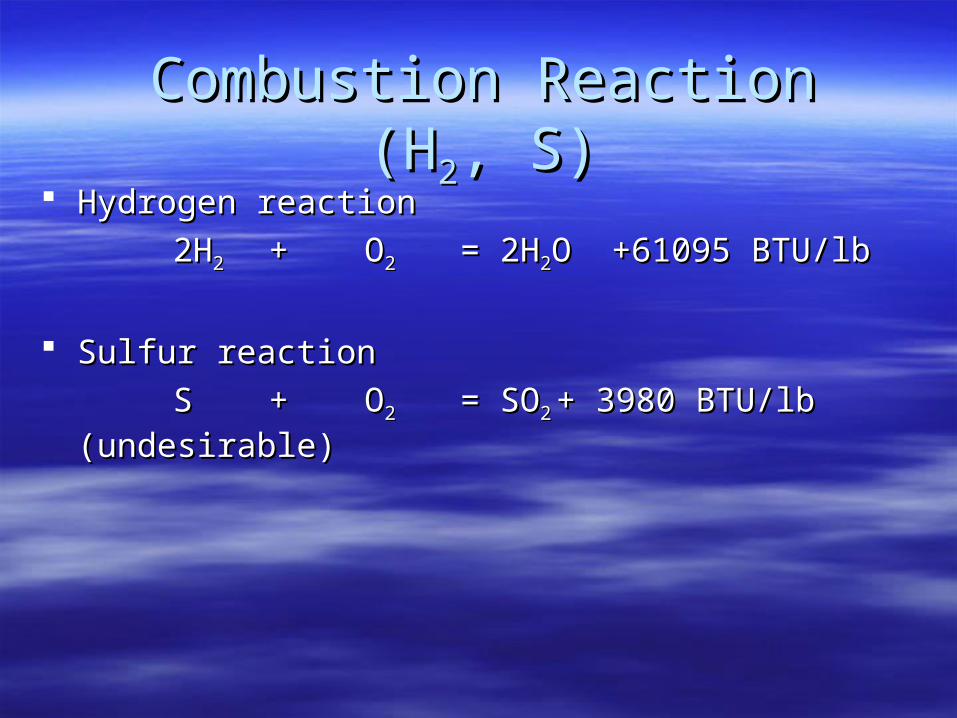
Combustion Reaction (HCombustion Reaction (H22, S), S) Hydrogen reactionHydrogen reaction
2H2H22 ++ OO22 = 2H= 2H22O +61095 BTU/lbO +61095 BTU/lb
Sulfur reactionSulfur reaction
SS ++ OO22 = SO= SO22 + 3980 BTU/lb + 3980 BTU/lb
(undesirable)(undesirable)
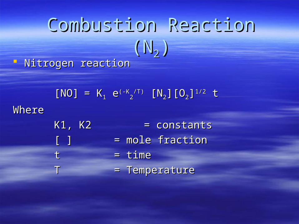
Combustion Reaction (NCombustion Reaction (N22)) Nitrogen reactionNitrogen reaction
[NO][NO] = K= K11 e e(-K(-K22
/T)/T) [N [N22][O][O22]]1/21/2 t t
WhereWhere
K1, K2K1, K2 = constants= constants
[ ] [ ] = mole fraction= mole fraction
tt = time= time
TT = Temperature= Temperature

Combustion airCombustion air
Theoretical air for complete combustion is known as Theoretical air for complete combustion is known as stoichiometric air.stoichiometric air.
Excess air for completion of combustion (20% at NCR i.e. Excess air for completion of combustion (20% at NCR i.e. 3.6% O3.6% O22))
Total combustion is divided asTotal combustion is divided as Primary airPrimary air For drying & pulverised coal transportationFor drying & pulverised coal transportation Secondary airSecondary airAdditional air for combustionAdditional air for combustion Ratio of SA/ PA = 2:1 (Approx)Ratio of SA/ PA = 2:1 (Approx)
%21
%
2
2
O
OExcessAir
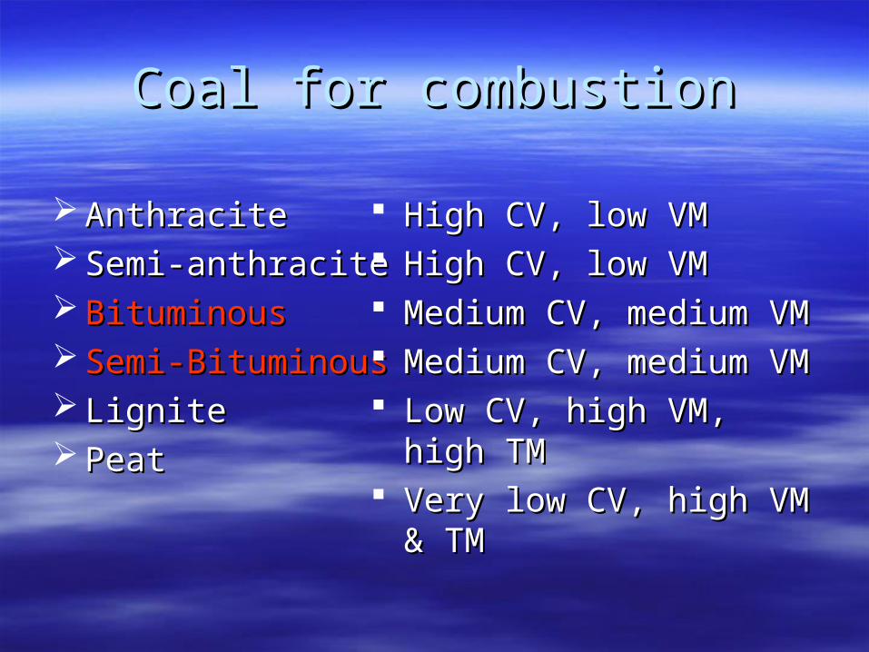
Coal for combustionCoal for combustion
AnthraciteAnthracite Semi-anthraciteSemi-anthracite BituminousBituminous Semi-BituminousSemi-Bituminous LigniteLignite PeatPeat
High CV, low VMHigh CV, low VM High CV, low VMHigh CV, low VM Medium CV, medium VMMedium CV, medium VM Medium CV, medium VMMedium CV, medium VM Low CV, high VM, high TMLow CV, high VM, high TM Very low CV, high VM & TMVery low CV, high VM & TM

Heat Generation in furnaceHeat Generation in furnace
Heat input in the furnace Heat input in the furnace
Efficiency of thermal power plants is 37%-45% for Efficiency of thermal power plants is 37%-45% for different types of cycledifferent types of cycle
For typical conventional P.F. boilers, coal flow rate For typical conventional P.F. boilers, coal flow rate is is
290-350 T/hr 290-350 T/hr For 500 MW unitsFor 500 MW units120-145 T/hr120-145 T/hr For 200 MW unitsFor 200 MW units
Cycle
ElectFurnace
MWQ

Arrangement of fuel input in Arrangement of fuel input in furnacefurnace
Coal is pulverized in mills at a fineness of 70% thru Coal is pulverized in mills at a fineness of 70% thru 200 mesh. Dried powdered coal is conveyed to 200 mesh. Dried powdered coal is conveyed to furnace (at a temperature < 95-100furnace (at a temperature < 95-100ooC)C)
Total coal flow is distributed among running mills and Total coal flow is distributed among running mills and fed thru coal burners at 20-25 m/sec.fed thru coal burners at 20-25 m/sec.
Coal flow is arranged in tiers. Maximum heat release Coal flow is arranged in tiers. Maximum heat release rate must not exceed plain area heat loading. It rate must not exceed plain area heat loading. It generates excessive NOgenerates excessive NOxx and making ash fused. and making ash fused.
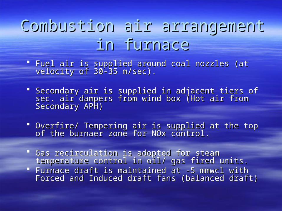
Combustion air arrangement in Combustion air arrangement in furnacefurnace
Fuel air is supplied around coal nozzles (at velocity of Fuel air is supplied around coal nozzles (at velocity of 30-35 m/sec).30-35 m/sec).
Secondary air is supplied in adjacent tiers of sec. air Secondary air is supplied in adjacent tiers of sec. air dampers from wind box (Hot air from Secondary APH)dampers from wind box (Hot air from Secondary APH)
Overfire/ Tempering air is supplied at the top of the Overfire/ Tempering air is supplied at the top of the burnaer zone for NOx control.burnaer zone for NOx control.
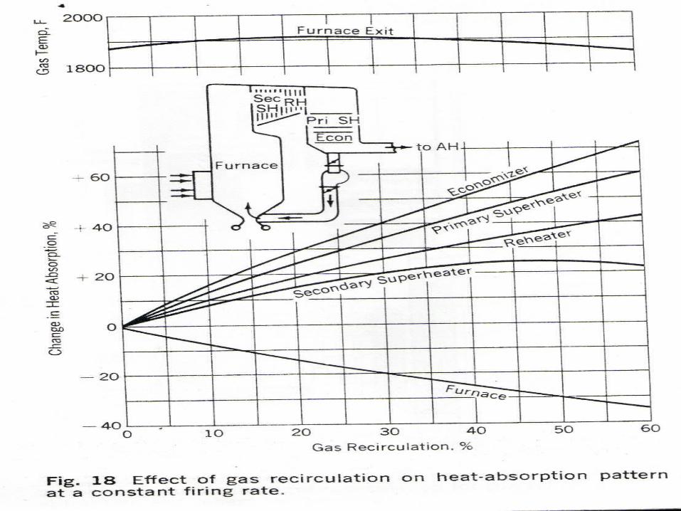
Gas recirculation is adopted for steam temperature Gas recirculation is adopted for steam temperature control in oil/ gas fired units.control in oil/ gas fired units.
Furnace draft is maintained at -5 mmwcl with Forced Furnace draft is maintained at -5 mmwcl with Forced and Induced draft fans (balanced draft)and Induced draft fans (balanced draft)


Method of firingMethod of firing
Down shot firingDown shot firing Front firedFront fired
Single wallSingle wallOpposed wallOpposed wall
Corner firedCorner fired Tangential tilted Tangential tilted -30-30oo to +30 to +30oo
Fluidized bed combustionFluidized bed combustion
For Anthracite (Low VM)For Anthracite (Low VM) Bituminous (Medium VM)Bituminous (Medium VM)
Bituminous (Medium VM)Bituminous (Medium VM)
Lignite, peat, garbage (For Lignite, peat, garbage (For low CV, high ash, high low CV, high ash, high Sulfur)Sulfur)Corner and Front fired furnaces are suitable for power plants
In India for Bituminous coals

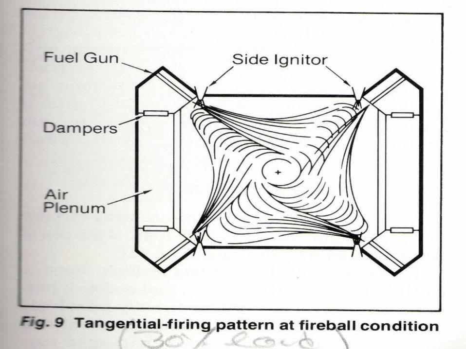
Tangential corner fired boilersTangential corner fired boilers
Suitable for sub bituminous and bituminous coalSuitable for sub bituminous and bituminous coal More uniform heat absorption in furnace walllsMore uniform heat absorption in furnace wallls Inherent feature of low NOInherent feature of low NOxx formation due air formation due air
deficit region at centredeficit region at centre Air plenum near walls reduce slagging and prevent Air plenum near walls reduce slagging and prevent
fireside corrosion.fireside corrosion. Arrangement of steam temperature control by Arrangement of steam temperature control by
tilting the coal burners (-30tilting the coal burners (-30oo to +30 to +30oo))

Furnace DesignFurnace Design
Heat generated in furnace is managed in Heat generated in furnace is managed in such a way that it fulfillssuch a way that it fulfills
1. 1. No dry out of waterwall tubesNo dry out of waterwall tubes
2. Enough residence time for combustion2. Enough residence time for combustion
3. Gas temperature before convection 3. Gas temperature before convection
super heater < Ash fusion temperaturesuper heater < Ash fusion temperature
4. Selection of metallurgy (Carbon steel Grade-C)4. Selection of metallurgy (Carbon steel Grade-C)
Furnace DesignFurnace Design
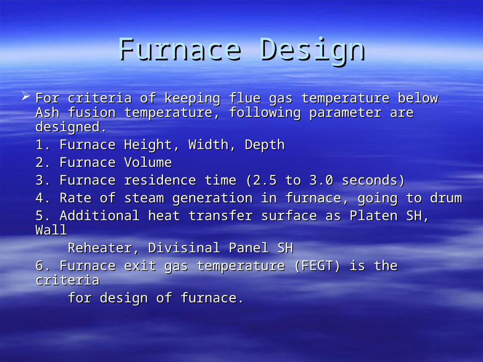
For criteria of keeping flue gas temperature below Ash For criteria of keeping flue gas temperature below Ash fusion temperature, following parameter are designed.fusion temperature, following parameter are designed.1. Furnace Height, Width, Depth1. Furnace Height, Width, Depth2. Furnace Volume2. Furnace Volume3. Furnace residence time (2.5 to 3.0 seconds)3. Furnace residence time (2.5 to 3.0 seconds)4. Rate of steam generation in furnace, going to drum4. Rate of steam generation in furnace, going to drum5. Additional heat transfer surface as Platen SH, Wall5. Additional heat transfer surface as Platen SH, Wall Reheater, Divisinal Panel SH Reheater, Divisinal Panel SH 6. Furnace exit gas temperature (FEGT) is the criteria 6. Furnace exit gas temperature (FEGT) is the criteria for design of furnace.for design of furnace.
Waterwall constructionWaterwall construction
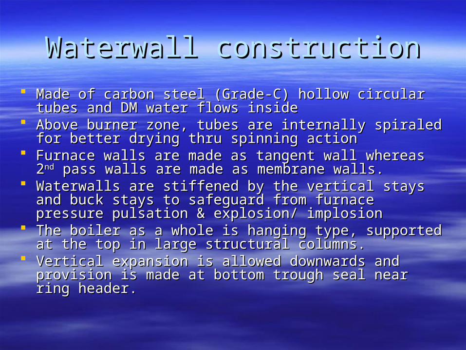
Made of carbon steel (Grade-C) hollow circular tubes and Made of carbon steel (Grade-C) hollow circular tubes and DM water flows insideDM water flows inside
Above burner zone, tubes are internally spiraled for better Above burner zone, tubes are internally spiraled for better drying thru spinning actiondrying thru spinning action
Furnace walls are made as tangent wall whereas 2Furnace walls are made as tangent wall whereas 2ndnd pass pass walls are made as membrane walls.walls are made as membrane walls.
Waterwalls are stiffened by the vertical stays and buck Waterwalls are stiffened by the vertical stays and buck stays to safeguard from furnace pressure pulsation & stays to safeguard from furnace pressure pulsation & explosion/ implosionexplosion/ implosion
The boiler as a whole is hanging type, supported at the top The boiler as a whole is hanging type, supported at the top in large structural columns.in large structural columns.
Vertical expansion is allowed downwards and provision is Vertical expansion is allowed downwards and provision is made at bottom trough seal near ring header. made at bottom trough seal near ring header.

Dry/ Wet bottom furnacesDry/ Wet bottom furnaces
Ash is characterized by Ash is characterized by 1. Initial deformation temperature1. Initial deformation temperature2. Ash fusion temperature (IDT-502. Ash fusion temperature (IDT-50ooC Approx)C Approx)3. Hemispherical temperature3. Hemispherical temperature4. Flow temperature4. Flow temperature
Indian coals are suitable for dry bottom furnace design only, Indian coals are suitable for dry bottom furnace design only, because of because of
a. High fuel ash (35-50%)a. High fuel ash (35-50%)b. High silica in ash (55-65% & vitrification temp. is 2000b. High silica in ash (55-65% & vitrification temp. is 2000ooK)K)c. High flow temperature (1600c. High flow temperature (1600ooC approx)C approx)

GOOSENECK
HORIZONTAL PASS
DOGHOUSE
FURNACE
BACKPASS
ARCH TUBES
Configuration of Dead chamber Steam drum
Downcomer
To APH
BCW p/p
w/w hangertubes
Screen tubes
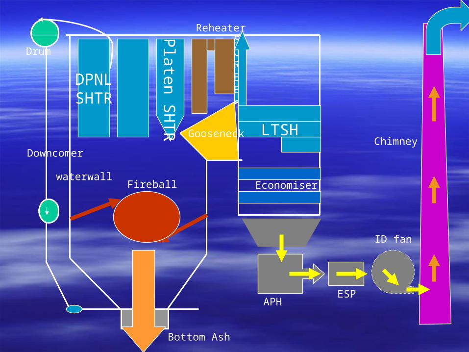
DPNLSHTR
Platen S
HT
R
SCREEn
LTSH
ESPAPH
ID fan
Chimney
Economiser
Bottom Ash
Downcomer
Drum
waterwallFireball
Gooseneck
Reheater

Steam generation principleSteam generation principle
Steam power plants operate Steam power plants operate on Rankine Cycle, DM water on Rankine Cycle, DM water as working fluid.as working fluid.
Sensible heat is added in Sensible heat is added in economiser +furnaceeconomiser +furnace
Steam generation takes place Steam generation takes place in waterwall.in waterwall.
Typical furnace efficiency is Typical furnace efficiency is 45% approx. 45% approx.
Heat transfer in furnace and Heat transfer in furnace and enclosed superheater takes enclosed superheater takes place thru radiation. place thru radiation.
condenserCEP
LPH
BFP
HPH+Ecow/w
SHHPTIPT
RH
LPT
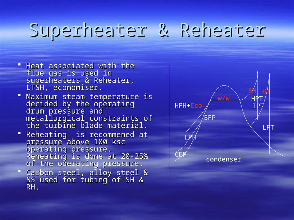
Superheater & ReheaterSuperheater & Reheater
Heat associated with the flue Heat associated with the flue gas is used in superheaters & gas is used in superheaters & Reheater, LTSH, economiser.Reheater, LTSH, economiser.
Maximum steam temperature is Maximum steam temperature is decided by the operating drum decided by the operating drum pressure and metallurgical pressure and metallurgical constraints of the turbine blade constraints of the turbine blade material.material.
Reheating is recommened at Reheating is recommened at pressure above 100 ksc pressure above 100 ksc operating pressure. Reheating operating pressure. Reheating is done at 20-25% of the is done at 20-25% of the operating pressure.operating pressure.
Carbon steel, alloy steel & SS Carbon steel, alloy steel & SS used for tubing of SH & RH.used for tubing of SH & RH.
condenserCEP
LPH
BFP
HPH+Ecow/w
SHHPTIPT
RH
LPT
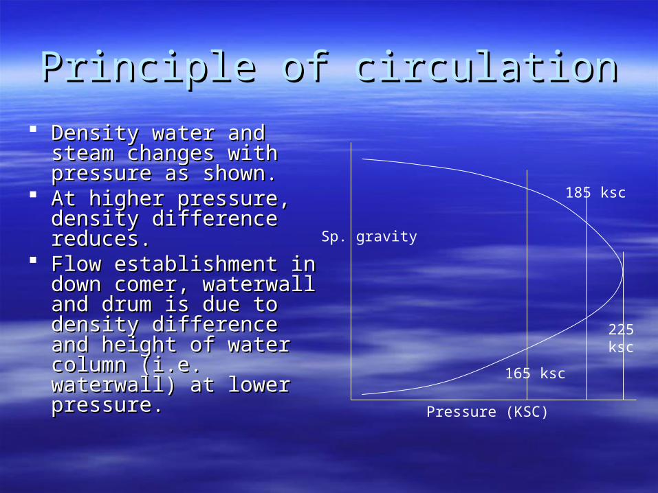
Principle of circulationPrinciple of circulation
Density water and steam Density water and steam changes with pressure as changes with pressure as shown.shown.
At higher pressure, At higher pressure, density difference density difference reduces.reduces.
Flow establishment in Flow establishment in down comer, waterwall down comer, waterwall and drum is due to and drum is due to density difference and density difference and height of water column height of water column (i.e. waterwall) at lower (i.e. waterwall) at lower pressure.pressure.
225ksc
185 ksc
165 ksc
Pressure (KSC)
Sp. gravity

Type of CirculationType of Circulation
Natural circulation Natural circulation (upto 165 ksc)(upto 165 ksc)
Forced/ assisted Forced/ assisted circulation (185-190 circulation (185-190 ksc)ksc)
Once thru boilerOnce thru boiler1. Sub critical1. Sub critical2. Supercritical2. Supercritical
Density difference & Density difference & height of water columnheight of water column
Assisted by external Assisted by external circulating pump (CC/ circulating pump (CC/ BCW pump)BCW pump)
Below 221.5 barBelow 221.5 bar 240-360 bar240-360 bar

Circulation ratioCirculation ratio
It may be defined as It may be defined as ratio of feed water flow ratio of feed water flow
thru down comers to the thru down comers to the steam generated in water steam generated in water wall.wall.
Ratio of the weight of 2-Ratio of the weight of 2-phase mixture to the phase mixture to the weight of dry steam in weight of dry steam in waterwall.waterwall.
Ratio of the total fluid Ratio of the total fluid contained to the weight of contained to the weight of the dry steam in the dry steam in waterwall.waterwall.
CR = 30-35 Industrial CR = 30-35 Industrial boilersboilers
CR = 6-8 Natrual cir. CR = 6-8 Natrual cir. BoilersBoilers
CR = 2-3 Forced cri. CR = 2-3 Forced cri. BoilersBoilers
CR = 1 Once thru boilersCR = 1 Once thru boilers (Sub (Sub
critical)critical) CR = 1 Supercritical CR = 1 Supercritical
boilersboilers

Representation of steam/ water Representation of steam/ water parameters on T-S diagramparameters on T-S diagram
3
2 1
1. Sub critical parameter2. Critical parameter,
(225.65 ksc/ 374.16oC)3. Supercritical parameter
Temperature
Entropy
374.16oC

Design concepts of once thru steam Design concepts of once thru steam generatorsgenerators
Mix locations
Ext
erna
l dow
ncom
ers
Ext
erna
l dow
ncom
ers
Feed
C/R pump
C/R flow
Valved control of furnace ckt
Controlled pointin circuitry
{0 from60% toFull Load}
Sulzer design
Combined C/Rdesign
Benson Design
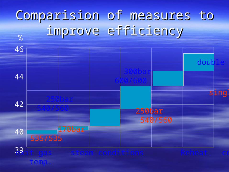
Comparision of measures to improve Comparision of measures to improve efficiencyefficiency
46
44
42
40
39
0.03 bar double 300bar 600/600
250bar 540/560 1201.15
0.065bar
single
250bar 540/560 170bar1.25 130 535/535
%
Excess exit gas steam conditions Reheat cond. PressureAir temp.

Effect of supercritical parameters Effect of supercritical parameters on efficiency (%)on efficiency (%)
Pressure/ TempPressure/ Temp 175 bar175 bar 245 bar245 bar 295 bar295 bar
540540ooC/ 540C/ 540ooCC Ref. Ref. 1.921.92 2.442.44
540540ooC/ 566C/ 566ooCC 0.720.72 2.742.74 3.333.33
565565ooC/ 565C/ 565ooCC 1.351.35 3.453.45 4.124.12
600600ooC/ 600C/ 600ooCC 3.103.10 5.305.30 6.096.09
600600ooC/620C/620ooCC 3.623.62 5.915.91 6.616.61Advantage
1. Saving on coal consumption on higher efficiency
2. Reduction in fuel handling system & pollution control.