bolero turbo (xl) - baristashopen.se · this document applies to the machines in its standard form....
TRANSCRIPT

�Copyright Bravilor Bonamat B.V.
Bolero Turbo (XL)OPERATING PRINCIPLE

�Copyright Bravilor Bonamat B.V.
© 2011 Bravilor® Bonamat®All rights reserved.
No part of this document may be copied and/or published by means of printing, photocopying, microfilmingor by any other means whatsoever without the prior written consent of the manufacturer. This applies equallyto the associated drawings and/or diagrams.
The information contained in this document is based on general data concerning the construction,materials characteristics and working methods known to us at the time of publication, so we reserve the rightto make changes without notice. For this reason the instructions contained in this document should betreated as a guide to the installation, use and maintenance and repair, of the machines indicated on the frontcover.
This document applies to the machines in its standard form. The manufacturer therefore accepts noliability for any damage or injury arising from specifications that deviate from the standard form of themachines as supplied to you.
Every possible care has been taken in the production of this document but the manufacturer accepts noliability for any errors in this document or for any consequences arising therefrom.

�Copyright Bravilor Bonamat B.V.
1. OPERATING PRINCIPLE 1. . . . . . . . . . . . . . . . . . . . . . . . . . . . . . . . . . . . . . . . . . 1.1 General operation 1. . . . . . . . . . . . . . . . . . . . . . . . . . . . . . . . . . . . . . . . . . . . . . . . . . . . . . 1.2 Water dosing system 2. . . . . . . . . . . . . . . . . . . . . . . . . . . . . . . . . . . . . . . . . . . . . . . . . . . 1.3 Start−up 3. . . . . . . . . . . . . . . . . . . . . . . . . . . . . . . . . . . . . . . . . . . . . . . . . . . . . . . . . . . . . . .
1.3.1 Initialisation 3. . . . . . . . . . . . . . . . . . . . . . . . . . . . . . . . . . . . . . . . . . . . . . . . . . . . . . . . 1.3.2 Filling 3. . . . . . . . . . . . . . . . . . . . . . . . . . . . . . . . . . . . . . . . . . . . . . . . . . . . . . . . . . . . . 1.3.3 Heating 3. . . . . . . . . . . . . . . . . . . . . . . . . . . . . . . . . . . . . . . . . . . . . . . . . . . . . . . . . . . . 1.3.4 Dosing 3. . . . . . . . . . . . . . . . . . . . . . . . . . . . . . . . . . . . . . . . . . . . . . . . . . . . . . . . . . . .
1.4 Powder dosing system 6. . . . . . . . . . . . . . . . . . . . . . . . . . . . . . . . . . . . . . . . . . . . . . . . . 1.5 Mixing system 7. . . . . . . . . . . . . . . . . . . . . . . . . . . . . . . . . . . . . . . . . . . . . . . . . . . . . . . . . 1.6 Ventilation system 7. . . . . . . . . . . . . . . . . . . . . . . . . . . . . . . . . . . . . . . . . . . . . . . . . . . . . 1.7 Operating system 8. . . . . . . . . . . . . . . . . . . . . . . . . . . . . . . . . . . . . . . . . . . . . . . . . . . . . .
1.7.1 Keyboard 8. . . . . . . . . . . . . . . . . . . . . . . . . . . . . . . . . . . . . . . . . . . . . . . . . . . . . . . . . . 1.7.2 Main board 8. . . . . . . . . . . . . . . . . . . . . . . . . . . . . . . . . . . . . . . . . . . . . . . . . . . . . . . . .
1.8 Hardware protections 9. . . . . . . . . . . . . . . . . . . . . . . . . . . . . . . . . . . . . . . . . . . . . . . . . . 1.8.1 Overflow protection 9. . . . . . . . . . . . . . . . . . . . . . . . . . . . . . . . . . . . . . . . . . . . . . . . . 1.8.2 Back−flow protection 9. . . . . . . . . . . . . . . . . . . . . . . . . . . . . . . . . . . . . . . . . . . . . . . . 1.8.3 Boiling protection 9. . . . . . . . . . . . . . . . . . . . . . . . . . . . . . . . . . . . . . . . . . . . . . . . . . . 1.8.4 High temperature safety switch 9. . . . . . . . . . . . . . . . . . . . . . . . . . . . . . . . . . . . . . .
1.9 Software protection 10. . . . . . . . . . . . . . . . . . . . . . . . . . . . . . . . . . . . . . . . . . . . . . . . . . . . 1.10 Programming 11. . . . . . . . . . . . . . . . . . . . . . . . . . . . . . . . . . . . . . . . . . . . . . . . . . . . . . . . . .

�Copyright Bravilor Bonamat B.V.
Fig. 1 The water dosing system 2. . . . . . . . . . . . . . . . . . . . . . . . . . . . . . . . . . . . . . . . . . . . . . . . . . . . . . . . Fig. 2 Float tank, complete 2. . . . . . . . . . . . . . . . . . . . . . . . . . . . . . . . . . . . . . . . . . . . . . . . . . . . . . . . . . . . Fig. 3 Water selector, complete 2. . . . . . . . . . . . . . . . . . . . . . . . . . . . . . . . . . . . . . . . . . . . . . . . . . . . . . . . . Fig. 4 Pump motor + rotor 3. . . . . . . . . . . . . . . . . . . . . . . . . . . . . . . . . . . . . . . . . . . . . . . . . . . . . . . . . . . . . Fig. 5 Pump housing 3. . . . . . . . . . . . . . . . . . . . . . . . . . . . . . . . . . . . . . . . . . . . . . . . . . . . . . . . . . . . . . . . . . Fig. 6 Encoder 4. . . . . . . . . . . . . . . . . . . . . . . . . . . . . . . . . . . . . . . . . . . . . . . . . . . . . . . . . . . . . . . . . . . . . . . Fig. 7 Water selector 4. . . . . . . . . . . . . . . . . . . . . . . . . . . . . . . . . . . . . . . . . . . . . . . . . . . . . . . . . . . . . . . . . . Fig. 8 Water selector internal 4. . . . . . . . . . . . . . . . . . . . . . . . . . . . . . . . . . . . . . . . . . . . . . . . . . . . . . . . . . . Fig. 9 Water distribution disc 4. . . . . . . . . . . . . . . . . . . . . . . . . . . . . . . . . . . . . . . . . . . . . . . . . . . . . . . . . . . Fig. 10 Water distribution disc 4. . . . . . . . . . . . . . . . . . . . . . . . . . . . . . . . . . . . . . . . . . . . . . . . . . . . . . . . . . Fig. 11 Water distribution disc with wide cam 5. . . . . . . . . . . . . . . . . . . . . . . . . . . . . . . . . . . . . . . . . . . . . Fig. 12 Water selector components 5. . . . . . . . . . . . . . . . . . . . . . . . . . . . . . . . . . . . . . . . . . . . . . . . . . . . . Fig. 13 Mixing unit 7. . . . . . . . . . . . . . . . . . . . . . . . . . . . . . . . . . . . . . . . . . . . . . . . . . . . . . . . . . . . . . . . . . . . Fig. 14 Exhaust hood 7. . . . . . . . . . . . . . . . . . . . . . . . . . . . . . . . . . . . . . . . . . . . . . . . . . . . . . . . . . . . . . . . . Fig. 15 Exhaust system for three mixing systems 7. . . . . . . . . . . . . . . . . . . . . . . . . . . . . . . . . . . . . . . . . Fig. 16 Ventilation system 7. . . . . . . . . . . . . . . . . . . . . . . . . . . . . . . . . . . . . . . . . . . . . . . . . . . . . . . . . . . . . Fig. 17 Drip tray water selector 9. . . . . . . . . . . . . . . . . . . . . . . . . . . . . . . . . . . . . . . . . . . . . . . . . . . . . . . . . Fig. 18 LCD display with error message 10. . . . . . . . . . . . . . . . . . . . . . . . . . . . . . . . . . . . . . . . . . . . . . . . . Fig. 19 Door open 11. . . . . . . . . . . . . . . . . . . . . . . . . . . . . . . . . . . . . . . . . . . . . . . . . . . . . . . . . . . . . . . . . . . . Fig. 20 Programming key 11. . . . . . . . . . . . . . . . . . . . . . . . . . . . . . . . . . . . . . . . . . . . . . . . . . . . . . . . . . . . . . Fig. 21 Total counter 11. . . . . . . . . . . . . . . . . . . . . . . . . . . . . . . . . . . . . . . . . . . . . . . . . . . . . . . . . . . . . . . . . . Fig. 22 Separate counter contents 11. . . . . . . . . . . . . . . . . . . . . . . . . . . . . . . . . . . . . . . . . . . . . . . . . . . . . . Fig. 23 Day counter 11. . . . . . . . . . . . . . . . . . . . . . . . . . . . . . . . . . . . . . . . . . . . . . . . . . . . . . . . . . . . . . . . . . . Fig. 24 Day counter to zero 11. . . . . . . . . . . . . . . . . . . . . . . . . . . . . . . . . . . . . . . . . . . . . . . . . . . . . . . . . . . . Fig. 25 General selection screen 12. . . . . . . . . . . . . . . . . . . . . . . . . . . . . . . . . . . . . . . . . . . . . . . . . . . . . . . Fig. 26 Default setting of the Timer (CL) 12. . . . . . . . . . . . . . . . . . . . . . . . . . . . . . . . . . . . . . . . . . . . . . . . . Fig. 27 Set current time 12. . . . . . . . . . . . . . . . . . . . . . . . . . . . . . . . . . . . . . . . . . . . . . . . . . . . . . . . . . . . . . . Fig. 28 Descaling symbol 12. . . . . . . . . . . . . . . . . . . . . . . . . . . . . . . . . . . . . . . . . . . . . . . . . . . . . . . . . . . . . . Fig. 29 First switching on time (P1) 13. . . . . . . . . . . . . . . . . . . . . . . . . . . . . . . . . . . . . . . . . . . . . . . . . . . . . Fig. 30 Set time (ON) 13. . . . . . . . . . . . . . . . . . . . . . . . . . . . . . . . . . . . . . . . . . . . . . . . . . . . . . . . . . . . . . . . . Fig. 31 First switching off time (P1) 13. . . . . . . . . . . . . . . . . . . . . . . . . . . . . . . . . . . . . . . . . . . . . . . . . . . . . Fig. 32 Set time (OFF) 13. . . . . . . . . . . . . . . . . . . . . . . . . . . . . . . . . . . . . . . . . . . . . . . . . . . . . . . . . . . . . . . . Fig. 33 Programming key / Door closed 13. . . . . . . . . . . . . . . . . . . . . . . . . . . . . . . . . . . . . . . . . . . . . . . . .

�Copyright Bravilor Bonamat B.V.
1. OPERATING PRINCIPLE
1.1 General operationThe machine works according to a pump systemdeveloped by Bravilor Bonamat. This system hasthe following advantages:� The components that are responsible for the
correct dosing of the water are housed in a coldwater unit. As a result, the largest cause of faultswith machines, the formation of scale on thedosing valves, is limited to a minimum.
� The float that regulates the water level is alsolocated in the cold−water circuit. This is anotherreason why the formation of scale is limited to aminimum.

�Copyright Bravilor Bonamat B.V.
1.2 Water dosing systemAfter a selection key is pressed, the pump motor isdriven with a controlled time and speed. The pumprotor displaces a certain amount of cold water fromthe cold water reservoir to the bottom of the boiler.As a result, the hot water in the boiler is pushedupwards towards a water selector. This selectoruses a rotating movement to select its position(beverage−dependent). Depending on the selectedbeverage, an ingredient is dosed which, togetherwith the dosed water, is or is not mixed and pouredinto a cup.
The water dosing system consists of the followingmain components:1. Magnetic valve2. Float tank3. Boiler4. Element5. Temperature sensor (NTC)6. Hot water selector7. Protection float tray8. Drain hose
Fig. 1 The water dosing system
ÁC
ÁÁÁÁ
ÁÁ
ÁÁ
A
B
ÁÁ
D
E
ÁÁÁÁ
F
Fig. 2 Float tank, complete
A. FloatB. Pump motorC.Pump rotorD.Pump housingE. Encoder
ÁÁA
ÁÁÁÁ
BÁÁÁÁ
C
ÁÁD
ÁÁÁÁ
E
Fig. 3 Water selector, complete
A. Water selector motorB. Top cover of water selectorC.Light sensorD.Water rotation diskE. Water distributor

�Copyright Bravilor Bonamat B.V.
1.3 Start−up1.3.1 Initialisation
The machine is switched on with the main switch.On the LCD (Liquid Crystal Display) the followingappear in succession:� all symbols that the display can show.
� the version number of the software(microprocessor) loaded from the factory.
� the version of the software table (Eeprom), alsoloaded from the factory.
This process takes approx. 3 seconds and ends withthe steaming cup in the LCD display to show thatthis phase has successfully finished.
1.3.2 Filling
The float tank and the boiler are connected by asiphon hose. Together, they form a communicatingvessel. When the machine is switched on for thefirst time, the float tank will be empty and the floatwill be low.� The magnetic valve is opened and fills water in
the float tank with a speed of 3,5 litres per minute,depending on the pressure.
� The water in the float tank flows to the boilerthrough the hose under the float tank.
� After the water level has pushed the floatupwards, the water level in the float tank is thesame as that of the boiler. The magnetic valve isswitched off.
� A signal sounds when the level of the float isreached.
Please note:Because the float tank is filled faster than the water”drops” to the boiler, the filling process will be madewith short intervals.
1.3.3 Heating
After the system is completely filled with water,element is switched on by means of a relay in themachine.
The lower temperature sensor measures the currenttemperature of the water. This ensures that thewater in the boiler is heated to the required finaltemperature. The upper temperature sensorreleases the machine for dosing or not. The heatingis switched off when the pre−set temperature hasbeen reached.
Hot water has a lower specific weight than coldwater. As a result, the hot water in the boiler will notwant to flow back to the float tank through thesiphon hose at the bottom. That part of the systemwill therefore remain cold. The latter is veryimportant because precisely the parts of the floattank are sensitive for scale.
1.3.4 Dosing
Dosing is allowed when:� The float is in the top position.
� The second temperature sensor measures atemperature higher than the blockingtemperature.
� After a selection key is pressed, the pump motor(fig.4 ) is driven for a certain time, depending onthe programmed amount, with a certain speed(number of revolutions).
Fig. 4 Pump motor + rotor
� The pump rotor rotates in the pump chamber,which is filled with water. This is formed by thebottom of the float tank and the underneath of thepump housing (fig.5 ).
Fig. 5 Pump housing
� The pump rotor pumps the water out of the pumpchamber, through the siphon hose in the bottomof the boiler.
� As a result, the hot water in the boiler is pushedout of the boiler.
� The float and the magnetic valve ensure that thelevel in the float tank is maintained and that waterremains in the pump chamber.

�Copyright Bravilor Bonamat B.V.
The volume of the displaced liquid (yield) is mainlydetermined by the time and speed of the pumpmotor.
The time that the motor is on is regulated from thesoftware and is very accurate.
The number of revolutions of the motor is measuredwith an active revolution counter.
Figure 6 shows that a disc is mounted on the shaftof the pump motor (A = Encoder). This disc rotatesat the same speed as the pump rotor.
The encoder rotates between a light sensor (B) andinterrupts a light beam. The interruption of the lightbeam is converted to pulses that can be read by theelectronics.
A B
Fig. 6 Encoder
This forms an active revolution regulation thatguarantees that, during the time that the pumpmotor is on, the speed and thus the water yieldremain constant.
Selection of the dosed hot water: This machine is fitted with a hot water selector. Thiscomponent (fig.7 ) is responsible for the dosed waterfrom the boiler being dosed in a minimum of 3 and amaximum of 6 directions (type−dependent).
Fig. 7 Water selector
Fig. 8 Water selector internal
Fig. 9 Water distribution disc
After the machine is switched on, the water selectorgoes to the stand−by position according to thefollowing procedure:� The water selector motor is driven.
� This motor uses a plastic worm to drive the waterdistribution disc (fig.8 / 9 ).
� The cams on the distribution disc interrupt thelight beam of the light sensor and pass thesepulses to the control (fig.10 ).
� When the light sensor observes the wide cam onthe distribution disc (fig.10 / 11 ), the initialposition is determined.
Fig. 10 Water distribution disc

�Copyright Bravilor Bonamat B.V.
Fig. 11 Water distribution disc with wide cam
Operation of the water selector after a selection keyis pressed:� Depending on the selected beverage, the water
selector determines its position.
� After the position is determined, the pump motoris driven.
� The dosed hot water is pumped into the top of thewater selector (fig.12 A).
� The water runs through the central hole of thedistribution disc (fig.12 B). It comes out through theslanted hole at the bottom (fig.12 C).
� After this, the water falls into one of the chambersin the bottom of the water selector (fig.12 D).
� The water runs to the relevant part through thehoses that are connected to the water selector.
� The water selector rotates back to its initialposition.
Please note:The arrow in fig.12 A shows a small hole on the topof the water selector cover. This is an aeration hole,which prevents siphoning. A hose, which goes to thetop of the float tank, is connected to the tulle.
Please note:Depending on the selected beverage, the waterselector can also rotate during the pumping. This isdone if water has to go to several mixing systems.
A B C DFig. 12 Water selector components

�Copyright Bravilor Bonamat B.V.
1.4 Powder dosing systemThe powder dosing system consists of an ingredientholder (canister) that is driven by a motor (canistermotor).
After the start key is pressed, the canister motor willrotate after a certain delay. This motor drives aworm, which transports the ingredient to the canisteroutlet.
The control of the canister motor makes it possibleto regulate timing and dosing speed independently.As a result, the ingredient can be poured into themixer at the same time that the water flows out.However, the canister motor will stop slightly earlierthan the water, to rinse the mixing jug clean.
Depending on the type of ingredient, “beatersprings” are used in the canister. These springsensure that less tunnel formation occurs. This is thecaking of ingredient against the walls.

�Copyright Bravilor Bonamat B.V.
1.5 Mixing systemThe mixing unit (fig.13 ) mixes the hot water and theingredient. After a selection key is pressed, thewater will be dosed in the mixing chamber after acertain delay. The product falls into the mixingchamber from above. Depending on the selectedbeverage, the mixer will start to rotate with a certainnumber of revolutions.
An exhaust opening is mounted on top of the mixingchamber (fig.14 ). This cover has an opening at therear, which is pressed into an exhaust openingthrough the sheet−metal work. The function of thisexhaust system is to ensure that vapour from themixing chamber does not get the chance to reachthe ingredient holder outlet. Figure 15 shows anexample of an exhaust system suited for threemixing systems.
Fig. 13 Mixing unit
Fig. 14 Exhaust hood
Fig. 15 Exhaust system for three mixing systems
1.6 Ventilation systemThe ventilation system (fig.16 ) removes the steam,that developes during dosing. So the settling ofwarm steam and condensation in the mixingchamber will be prevented. Therefore the mixingchamber will get less dirty.
Fig. 16 Ventilation system

�Copyright Bravilor Bonamat B.V.
1.7 Operating systemThe operating system consists of a:� Keyboard
� Main board
1.7.1 Keyboard
The keyboard is located on the front of the machineand contains various keys and the display. Savedsettings such as the dosing quantities, counters, etc.are stored here. When this circuit board is replaced,the customer−specific settings will be lost. A flatcable connects the keyboard to the main board inthe machine.
1.7.2 Main board
The main board is located on the rear inside themachine and it is supplied from an externaltransformer. This board contains inputs and outputsof the machine.

�Copyright Bravilor Bonamat B.V.
1.8 Hardware protectionsThe machine is equipped with a number of hardwareprotections. These protections ensure that nodangerous situations can arise, such as overheatingand/or water in the machine.
1.8.1 Overflow protection
This protection is in the float tank and ensures that,if the water becomes too high, excess water ispassed through the overflow and hose to the bottomof the machine.
1.8.2 Back−flow protection
The water from the magnetic valve is sprayedagainst the cover of the float tank, via a pipe in thefloat tank. Then, it goes into the float tank itself. Inthis way, water is prevented from flowing back intothe system and getting into the water system if thewater pressure is released from the magnetic valve.
1.8.3 Boiling protection
The element is controlled by a relay on the mainboard. A so−called safety relay has been connectedin series with this relay. If a fault occurs and theelement is still under tension, the safety relay willinterrupt this tension (see the electrical diagram) andprevent boiling dry.
1.8.4 High temperature safetyswitch
The boiling−dry protection is mounted on the outsideof the boiler by means of two Klixons. If the boiler,for whatever reason, is not switched off by thecontrol, the Klixons make sure that the voltage onthe element is mechanically switched off to preventoverheating.
During the boiling dry process, evaporation escapesfrom the boiler. This vapour enters the waterselector and can possibly exit between the coverand distributor. To prevent a few drops from enteringthe machine, a drip tray for the water selector hasbeen made (fig.17 ).
Fig. 17 Drip tray water selector

�Copyright Bravilor Bonamat B.V.
1.9 Software protectionThe machine has been equipped with a number ofsoftware protections; the software monitors all inputsand outputs of the machine throughout the process.If non−allowed situations arise, the software willintervene. This intervention results in the machinebeing switched off and an error message beingshown on the display.
Fig. 18 LCD display with error message
ERROR LIST
Error 1 Not applicable
Error 2 Temperature in boiler too high:− If the temperature sensor (NTC) measures a
value that is outside its range (0 Ohm orinfinity), the machine is switched off and’Error 2’ appears in the LCD display. Thisalso applies if the boiling protection (seehardware protection) is activated.
Error 3 Magnetic valve open without selection /Heating process takes too long:
− When a dosing key is pressed, the magneticvalve is enabled. If this valve is enabledwithout pressing the start key, a timer isactivated. If the magnetic valve is enabledmore than three times within 15 minuteswithout the start key being pressed, thisindicates that there is a leakage in the watersystem or that the water is boiling. In thatcase the machine is switched off.
− At the moment that the float in the protectionwater tray has reached the upper positiononce, the software enables the protectionrelay and all elements are switched offimmediately. In this case the machine willnot be switched off, but show error 3 after 15minutes.� Reset the machine after having remedied the
fault. This resetting is done by pressing thereset key on the main board through the holein the rear panel using a small screwdriver(see figure). After this switch off the machineand on again to make the error code 3disappear from the screen.
Error 4 Not applicable
Error 5 Water selector in wrong position:− The water selector returns to its initial
position during start−up and after eachdosing. If the selector cannot find its positionduring the execution of this routine, itswitches off and ’Error 5’ appears in the LCDdisplay.
Error 6 Magnetic valve opened too long:− If, for whatever reason, the process of filling
the float tank takes too long, the machine isswitched off and ’Error 6’ appears in the LCDdisplay.
Error 7 Wrong Chip card:− In a number of cases, it is possible to place
a chip card in a chip card reader. This ispresent on the keyboard. Any data presentcan be downloaded or uploaded. If thesoftware on this chip card does notcorrespond with the software in the machine,’Error 7’ appears in the LCD display.
Error 8 Communication error between both prints:− There is constant communication during
machine start−up and during use. This isdone via the flatcable between the keyboardand the main board. If communication isimpossible, ’Error 8’ appears in the LCDdisplay.
Error 9 Pump motor rotates too slow or does notrotate at all:
− The pump motor is rotating during machinestart−up and during use. The light sensordetects no or too little pulses and ’Error 9’will appear in the LCD display.

�Copyright Bravilor Bonamat B.V.
1.10 ProgrammingThe programming is built up by means of a simpleprogramming carrousel. Have the user instructionsopen next to this text. After the programming isactivated by means of the programming key,settings can be simply activated or changed. Bypressing the programming key again, the settingsare saved the machine returns to the standby mode.1. Open the door with the key.
Fig. 19 Door open2. Press the programming key P to start the
programming sequence.
Fig. 20 Programming key3. Counter contents read−out of all beverages at
the same time. The display shows a 3− and6−digit number alternately:
− The 3−digit number denotes the total number ofunits that were poured since the counter settingswere last reset to zero (day counter).
− The 6−digit number denotes the total number ofunits that were poured since the machine was putinto operation (total counter).
Fig. 21 Total counter
3.1 Separate read−out of counter contents ofpoured beverages:
− Select the desired beverage with one of theselection buttons. The relevant countercontents will appear in the LCD display. Aftera few seconds, the counter contents return tothe counter of all beverages at the same time.
Fig. 22 Separate counter contents3.2 Resetting day counter:
− Select any beverage using one of theselection buttons.
− Keep the desired selection button presseduntil the day counter is set at 0.
Fig. 23 Day counter
Fig. 24 Day counter to zero− Press the Enter key to go to the general
selection screen (fig.25 ).4. General selection screen:− General programming: press the Enter key and
continue with point 5.− Beverage−dependent settings: press the
selection key and continue with point 13.

�Copyright Bravilor Bonamat B.V.
Fig. 25 General selection screen5. Setting the timer (CL):− The default setting of the timer is OFF, see
fig.26 . Beverages can be pourred at any time.
− When the timer (CL) is set at ON, it is possibleto switch the machine on and off at a maximum offour various times. Only during these times hotbeverages can be poured from the machine. Onlyhot water can be poured at all times! If thesetting is changed to ON, the current time has tobe set, see fig.27 . This time will appear asdefault on the display. To set the various times,go to point 12.
Fig. 26 Default setting of the Timer (CL)
Fig. 27 Set current time
6. Descaling program:− This machine is fitted with a descaling program.
After the START key is pressed in this state ofthe LCD display, the de−scaling program isstarted. (For this purpose, read the relevantsection of the user instructions.)
− Press CANCEL within 5 seconds if you decidenot to start the de−scaling program.
7. Preselect the cup/mug/jug setting:− The machine will return to the set preference
after having distributed the drink or after acertain time.
8. Boiler temperature:− Set the temperature of the water in the boiler.
(−5°C − +5°C)9. Descaling signal:− Ask your local water company about the hardness
of the water supply. Always select the rightsetting. The default setting of the machine isposition 3 (1000L). The machine continuouslyregisters the time that the inlet valve is open andtherefore the number of litres of water that haspassed through the system. When the number ofregistered litres is greater than or equal to theprogrammed value, the descaling symbol in theLCD display starts to flash.
− The positions 6 − 9 are reserved for the use of awater softening filter preceding the machine.Always choose the correct setting thatcorresponds with the capacity of the watersoftening filter.
Fig. 28 Descaling symbol10. Energy−saving mode:− Setting the number of minutes/hours, after which
the machine must switch over to the ECO mode.All functions such as boiler, ventilator anddisplay illumination switch off and [ECO]appears in the LCD display. The next time that aselection key is pressed, the machine switcheson again. Depending on the switch−off time, itcan take a few minutes before the machine isready for use again.
11. Copy Card:− Customer−specific settings can be copied to the
chip card, after which they can be downloadedto other equivalent machines.
− The procedure can be found on the extranetunder ’Special codes’.
12. Now set the on− and off swichting times. Amaximum of four times can be set in succession,P1 till P4. Beware of the fact that the times donot overlap!
�Copyright Bravilor Bonamat B.V.
Fig. 29 First switching on time (P1)
Fig. 30 Set time (ON)
Fig. 31 First switching off time (P1)
Fig. 32 Set time (OFF)
13. General selection screen (all keys that are nowlit can be selected).
14. Amount drink dependent (cup/mug/decanter).− Setting the amount of water in ml. The software
will convert a larger amount to a longer pumpingtime. If the amount of water is changed, thebasic strength is automatically adapted, so thatthe strength increases or decreasesproportionally.
14.1 Block dosing:− Decrease the set value to the minimum. The
display will show ’OFF’.15. Basic strength (drink dependent):− Setting amount of ingredient (in %). The
software translates the programmed percentageto the speed of the canister motor and thereforethe strength of the ingredient. (See ingredientsheet).
16. General selection screen.17. Programming (hot water):18. Amount hot water (cup/mug/decanter).− Here, the amount of water can be set in ml. The
software will convert a larger amount to a longerpumping time.
18.1 Blocking amount:− Decrease the value set to the minimum. The
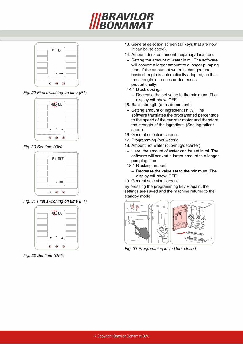
display will show ’OFF’.19. General selection screen.By pressing the programming key P again, thesettings are saved and the machine returns to thestandby mode.
Fig. 33 Programming key / Door closed

�Copyright Bravilor Bonamat B.V.
© 07−2011