bombardier cityflo
TRANSCRIPT

捷運技術半年刊 第 35 期 95 年 8 月
77
CITYFLO 650 System Overview
BOMBARDIER Company Jeffrey S. Stover
Abstract
Bombardier Transportation has invested significant efforts in streamlining the products, technologies and capability; and has structured its signalling solutions in the most comprehensive, cohesive and upgradeable product lines. The products have been organized into two main structures: Bombardier* INTERFLO* for mainline solutions and Bombardier* CITYFLO* for urban needs. The CITYFLO system provides complete urban railway solutions for all types of mass transit such as trams, light rail vehicles and metros to suit various operating modes and customer’s need. These include cab signalling, semi-automatic train operation, driverless and unattended train operation. The systems can be expanded to the customer’s growing requirements and thus meet the operational demands for the entire life of the system.
Key Words:INTERFLO, CITYFLO, CBTC, ATO, ATP, ATS, ATC
CITYFLO 650 系統介紹
龐巴迪公司
摘 要
龐巴迪運輸部門投入相當大的努力於整合相關系列的產品、技術及能力,建構一系列號誌系統成為完整且具結合能力及易於升級的產品,此產品主要分成兩類:Bombardier* INTERFLO*作為解決主要幹線交通之系統,Bombardier* CITYFLO*作為解決都市交通之系統。對於各種運量需求之交通工具,諸如電車、輕軌列車及地下鐵,CITYFLO 系統提供了都市型軌道系統完整的解決方案,這些包括了具司機員之半自動列車操作,無司機員及無站務人員之全自動列車操作,此系統並可擴充以應業主營運成長之需求,進而滿足系統最大年限內操作之要求。
關鍵字:INTERFLO、CITYFLO、通訊式列車控制系統、自動列車操作、自動列車保護、自動列車監督、自動列車控制。
龐巴迪公司 [email protected]:er.com
Jeffrey S. Stover CITYFLO 650 System Overview
78
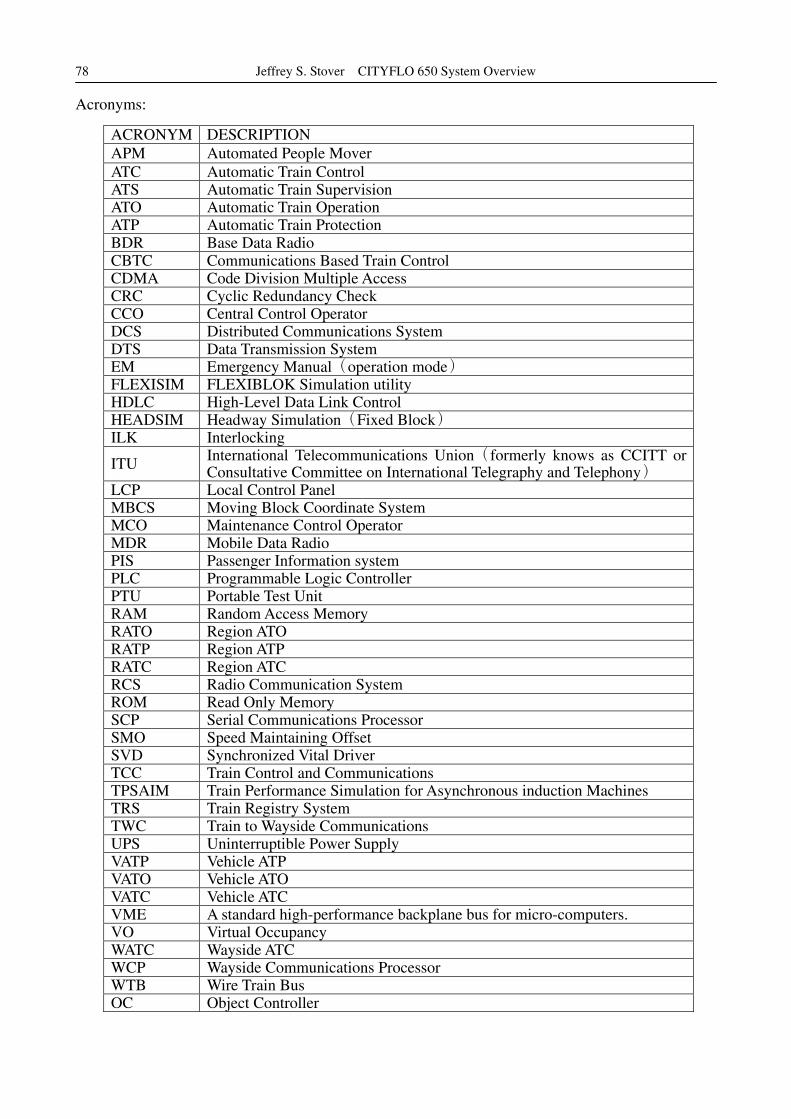
Acronyms:
ACRONYM DESCRIPTION APM Automated People Mover ATC Automatic Train Control ATS Automatic Train Supervision ATO Automatic Train Operation ATP Automatic Train Protection BDR Base Data Radio CBTC Communications Based Train Control CDMA Code Division Multiple Access CRC Cyclic Redundancy Check CCO Central Control Operator DCS Distributed Communications System DTS Data Transmission System EM Emergency Manual(operation mode) FLEXISIM FLEXIBLOK Simulation utility HDLC High-Level Data Link Control HEADSIM Headway Simulation(Fixed Block) ILK Interlocking
ITU International Telecommunications Union(formerly knows as CCITT or Consultative Committee on International Telegraphy and Telephony)
LCP Local Control Panel MBCS Moving Block Coordinate System MCO Maintenance Control Operator MDR Mobile Data Radio PIS Passenger Information system PLC Programmable Logic Controller PTU Portable Test Unit RAM Random Access Memory RATO Region ATO RATP Region ATP RATC Region ATC RCS Radio Communication System ROM Read Only Memory SCP Serial Communications Processor SMO Speed Maintaining Offset SVD Synchronized Vital Driver TCC Train Control and Communications TPSAIM Train Performance Simulation for Asynchronous induction Machines TRS Train Registry System TWC Train to Wayside Communications UPS Uninterruptible Power Supply VATP Vehicle ATP VATO Vehicle ATO VATC Vehicle ATC VME A standard high-performance backplane bus for micro-computers. VO Virtual Occupancy WATC Wayside ATC WCP Wayside Communications Processor WTB Wire Train Bus OC Object Controller

捷運技術半年刊 第 35 期 95 年 8 月
79
1、Introduction
Increased urbanization, economic prosperity, cost of fuel, road congestion and environmental issues are driving a revival in the mass transit market. These issues are driving the need for efficient and effective mass transit systems, and the rail industry is faced with a challenge to provide a more efficient way to transport people with higher reliability at a lower cost.
One significant domain in railway transportation is the train control system. The train control systems required to address the needs of the global mass transit market cover a wide range from basic line of sight signalling systems up to the unattended train operation system also called UTO. The signalling and train control products are among the components that contribute most to the enhanced performance of the railways. Over the last decade the railway industry has invested significant research and development effort to improve the train control systems, taking advantage of the technologies and innovations now available on the market.
Bombardier Transportation has invested significant efforts in streamlining the products, technologies and capability; and has structured its signalling solutions in the most comprehensive, cohesive and upgradeable product lines. The products have been organized into two main structures: Bombardier* INTERFLO* for mainline solutions and Bombardier* CITYFLO* for urban needs.
The INTERFLO system offers complete mainline solutions individually tailored to the customer’s need, encompassing integrated operations control systems and computerized interlocking systems, as well as automatic train protection and wayside equipment.
The CITYFLO system provides complete urban railway solutions for all types of mass transit such as trams, light rail vehicles and metros to suit various operating modes and customer’s need. These include cab signalling, semi-automatic train operation, driverless and unattended train operation. The systems can be expanded to the customer’s growing requirements and thus meet the operational demands for the entire life of the system.
The various solutions and applications are summarized below.
INTERFLO 50 GPS-based train location and information system INTERFLO 100 Conventional regional line system INTERFLO 150 Radio-based regional / industrial line, including ERTMS based system INTERFLO 200 Conventional main line system INTERFLO 250 ERTMS Level 1 e.g. Taiwan ATP contract INTERFLO 350 Continuous track based communication system INTERFLO 450 ERTMS Level 2
CITYFLO 150 Manual tram / LRV control system and onboard CITYFLO 250 Cab signalled mass transit system, non CBTC, fixed block CITYFLO 350 STO metro system, non CBTC, fixed block CITYFLO 450 STO CBTC, variable block CITYFLO 550 Automated(DTO/UTO)system, non CBTC, fixed block CITYFLO 650 Automated(DTO/UTO)CBTC moving block system
*Trademarks of Bombardier Inc and its subsidiaries

Jeffrey S. Stover CITYFLO 650 System Overview
80
The CITYFLO 650 solution is a Communication-Based Train Control(CBTC) system that does not require track circuits or an onboard operator, making it an ideal choice for new(green field) installations. CITYFLO 650 can also be used as an overlay train control system to upgrade existing fixed block(brown field)systems. It can be made to support mixed-mode operation and the graceful upgrade and expansion of any metro as the wayside and vehicle equipment are systematically upgraded through a retrofit program, eventually yielding improved transport capacity, permitting higher speeds and greater regularity, reliability and utilization of the rolling stock assets.
1.1 CITYFLO 650 Design Features
CITYFLO 650 is a “state-of-the-art” system that uses the moving block technique to manage the trains in a railway network - assuring the highest level of system performance, flexibility, safety, reliability and availability. CITYFLO 650 uses service proven components, including up to date CBTC products that have evolved from traditional ATC systems with a long service history in rail transit. This evolution dates back to the 1970s with the fixed-block automatic train control technology provided for San Francisco’s Bay Area Rapid Transit (BART).
The CITYFLO 650 ATC provides:
˙Inherent bi-directional operation
˙Continuous real-time data communication independent of track circuits
It fulfils the requirements of a communication-based system in a transit environment, using the most advanced technology in the world. The key features of the system are:
˙Fully operational redundant configuration
˙Distributed system architecture
˙Reliable radio communications
˙Ease of adaptation to scheme plan or track layout changes
˙Automatic Restart (Train Registry System)
˙CITYFLO Monitoring System (CFMS)
˙Industry standard interfaces
˙Low life cycle costs
1.2 Increased Safety
The CITYFLO 650 solution uses checked redundancy to maintain or improve safety compared to traditional train control equipment. Inexpensive to install, the CITYFLO 650 solution eliminates wayside equipment due to its simple, reliable contact-less train-to wayside communications systems, thereby permitting shorter, more consistent headways.
The system uses the EBI Com radio block centre which detects trains through the position sent by the radio and controls the EBI Switch point machines. EBI Link wayside equipment ‘tags’ are used as norming points to correct position measurement errors.
The EBI Cab onboard ATP ensures that the train does not exceed the permitted speeds or violates the end of a movement authority.
1.3 Automatic Startup(Train Registry System)
In traditional CBTC systems, at cold start-up or after a complete shut-down due to failure, the

捷運技術半年刊 第 35 期 95 年 8 月
81
initialization process entails a complete “manual sweep” of the entire region to clear the “blocked segments”. The sweeping is usually performed by technicians by driving the trains manually through all segments in the region. This is a very time consuming process and can take a few hours for a large metro before restoring the operation. This is considered as a major weakness in the CBTC systems.
The Train Registry System(TRS)within the CITYFLO 650 solution consists of an independent vital computer that maintains a record of all trains operating within a certain pre-defined area. This information is communicated to the Automatic Train Protection(ATP), which then polls and established communication with all the trains in the system. This obviates the need for any manual sweeping and the auto operation can be resumed within a very short time, usually a few minutes.
1.4 Greater Capacity
The Automatic Train Operation(ATO)system fully exploits the capacity of the system as the train travels along the line at a fixed and safe distance from other trains. The ATO ensures smooth braking and acceleration, resulting in reduced power consumption and wear on the track and vehicles.
The ATO system also provides precision stopping at platforms, automatic door operation and the automatic turnback at the terminal stations. The system uses the EBI Screen control room to provide the metro operator total overview and control of the traffic.
1.5 Availability
CITYFLO 650 provides a fully redundant, ATP and ATO supervised operation to ensure high availability. The system is also capable to work with a separate fall back capability for metro operation, with manual train operation, in the unlikely event that the fully automated systems are inoperable.
1.6 CITYFLO Monitoring System(CFMS)
Another salient feature of the CITYFLO 650 system is its ability to record system data and play back any event that took place in the system. In case of an incident, the CFMS will ease the identification of the problem and will help to determine the root cause.
In a live railway, CFMS allows identification of the potential problems even before they occur and allow preventive actions in order to improve the availability of the system.
The CFMS tool is also used during the initial system start-up to shorten the development effort and also during factory and field-testing, making it easier and faster to implement and test the CITYFLO 650 system.
1.7 CITYFLO 650: The System of Choice
CITYFLO 650 is currently in service at the San Francisco, Seattle-Tacoma(SeaTac)and the Dallas/Fort Worth(DFW)International Airport Automated People Movers.
The system also is working at the South East Pennsylvania Transit Authority(SEPTA)for a steel-wheel LRT tunnel system, albeit in limited operation until all the drivers are trained on the system.
In addition, CITYFLO 650 is currently being implemented at London Heathrow Terminal 5 Automated People Mover(UK)and the Yongin EverLine Automated Rapid Transit(South Korea). These projects are currently underway and the systems are scheduled for operation in the next two

Jeffrey S. Stover CITYFLO 650 System Overview
82
to three years.
Most recently, Madrid Metro(Spain)has endorsed the CITYFLO solution as its preferred choice for the ATC upgrade of two of its most important lines, lines 1 and 6, which carry more than 200 million passengers every year.
2、CITYFLO 650:Functional Description
The purpose of this section is to provide an overview of CITYFLO 650 train control system, including basic concepts and definitions necessary to understand the terms “Moving Block”, “Communications-Based Train Control System”, the CITYFLO 650 system architecture and some information about CITYFLO 650 system availability.
2.1 Moving Block Concept
Unlike the traditional “fixed-block” systems, in which the train occupancy is generated by occupancy of a fixed-length track circuit(or axle counter)section(referred to as a block), in a “moving-block” system, the “occupancy” of the train moves along with the train in a continuous fashion and that the length of the block deemed occupied by the train also depends on the speed of the train.
2.2 Communication-Based Train Control
In a “Communications-Based Train Control” system, the information controlling the train is transmitted between the train and wayside computers through a radio link, capable of bi-directional transmission. CITYFLO 650 is a “contact-less” system, which requires neither track circuits nor an on-board operator to provide a completely automated operation.
2.3 System Architecture
Like most modern train control systems, the CITYFLO 650 ATC is divided into various sub-systems, based upon function and modular hardware and software. The following figure illustrates the Train Control System Architecture for a typical metro installation.
Figure 1: CITYFLO 650 Train Control System Architecture
捷運技術半年刊 第 35 期 95 年 8 月
83
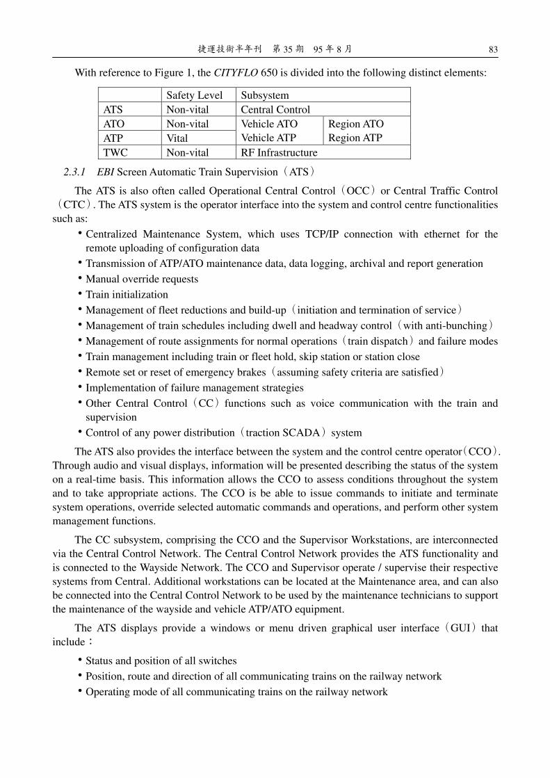
With reference to Figure 1, the CITYFLO 650 is divided into the following distinct elements:
Safety Level Subsystem ATS Non-vital Central Control ATO Non-vital ATP Vital
Vehicle ATO Vehicle ATP
Region ATO Region ATP
TWC Non-vital RF Infrastructure
2.3.1 EBI Screen Automatic Train Supervision(ATS)
The ATS is also often called Operational Central Control(OCC)or Central Traffic Control (CTC). The ATS system is the operator interface into the system and control centre functionalities such as:
˙Centralized Maintenance System, which uses TCP/IP connection with ethernet for the remote uploading of configuration data
˙Transmission of ATP/ATO maintenance data, data logging, archival and report generation
˙Manual override requests
˙Train initialization
˙Management of fleet reductions and build-up(initiation and termination of service)
˙Management of train schedules including dwell and headway control(with anti-bunching)
˙Management of route assignments for normal operations(train dispatch)and failure modes
˙Train management including train or fleet hold, skip station or station close
˙Remote set or reset of emergency brakes(assuming safety criteria are satisfied)
˙Implementation of failure management strategies
˙Other Central Control(CC)functions such as voice communication with the train and supervision
˙Control of any power distribution(traction SCADA)system
The ATS also provides the interface between the system and the control centre operator(CCO). Through audio and visual displays, information will be presented describing the status of the system on a real-time basis. This information allows the CCO to assess conditions throughout the system and to take appropriate actions. The CCO is be able to issue commands to initiate and terminate system operations, override selected automatic commands and operations, and perform other system management functions.
The CC subsystem, comprising the CCO and the Supervisor Workstations, are interconnected via the Central Control Network. The Central Control Network provides the ATS functionality and is connected to the Wayside Network. The CCO and Supervisor operate / supervise their respective systems from Central. Additional workstations can be located at the Maintenance area, and can also be connected into the Central Control Network to be used by the maintenance technicians to support the maintenance of the wayside and vehicle ATP/ATO equipment.
The ATS displays provide a windows or menu driven graphical user interface(GUI)that include:
˙Status and position of all switches
˙Position, route and direction of all communicating trains on the railway network
˙Operating mode of all communicating trains on the railway network

Jeffrey S. Stover CITYFLO 650 System Overview
84
˙Displays of system performance and status
˙Remote intervention to control and override system operations
˙Messages and alarms of abnormal/malfunction conditions
˙Status of major vehicle alarms including smoke detectors
˙Data recording and reporting
Figure 2:Example of Train Control Screen
The ATS also includes data loggers to record all operational data. The data can then be displayed and used for reports as necessary. This includes any unscheduled stoppages or delays, including time of occurrence and time of resumption of operation complete with the identification number for the train.
In the event that the ATS fails, for example, through a catastrophic failure, the system continues to operate with trains running according to their current schedule and headway regulation, which is controlled by the RATO.
The ATS system monitors and manages the overall system operation. The ATS is not essential to continuing automatic system operations by the ATO and ATP once operations have been started.
2.3.2 Automatic Train Control(ATC)
The ATC system is divided into two sub-components, wayside and onboard.
The Wayside ATC is divided into a number of regions or geographic areas for each metro line and the number of regions used for a specific line depends on the length of that line and the number of trains on the line. Often the term “Region ATC” is used as a general term. “Region ATC” refers to a complete set of Region Control equipment which includes, but is not necessarily limited to, Region ATP, Region ATO and TWC Equipment. Each Region ATC can control several interlockings (collection of switches or points);therefore the ATC equipment may be centralized at one station.
The Region ATP, Region ATO, and remote Region ATP computer systems are responsible for the safe and optimal performance of the CITYFLO 650 Train Control system. Information flows between these sub-systems through the Wayside Network backbone and through to the Central Control Network.

捷運技術半年刊 第 35 期 95 年 8 月
85
Each train has two sets of vehicle ATC(VATC)equipment so that redundancy is achieved within each train. The train location is determined based on tachometer readings from wheel axles or gears.
Due to tolerances in equipment and wheel diameter, positioning errors may accumulate. Norming points are therefore located along the track to allow the vehicle to reposition itself periodically. Each norming point is a passive tag that is energized and read by a transponder interrogator mounted on the vehicle as the vehicle passes over.
The ATC components, both wayside and onboard are divided into two sub-systems, provided below.
2.3.2.1 EBI Cab Automatic Train Protection(ATP)
The EBI Cab system is responsible for the safety aspects of the train control system. The wayside component is referred to as a Region ATP)RATP)and the onboard component as Vehicle ATP(VATP). The VATP is responsible for the safe operation of the train including safe train movement and occupancy generation.
In a CITYFLO 650 system, the ATP systems perform the safety critical tasks such as:
˙Train Occupancy Detection(RATP and VATP)
˙Safe Train Separation(RATP)
˙Roll-back Protection and Direction Control(VATP)
˙Overspeed Protection(VATP)
˙Propulsion and Braking Interlocks(VATP)
˙Parted-Train Protection(VATP)
˙Switch Interlocking Control(RATP)
˙Occupancy Generation(VATP)
˙Door Control Enabling and Interlocking(VATP)
˙Route setting and interlocking
Each Region ATP consists of an independent primary and backup system. Each primary and backup ATP system interfaces with an independent regional ATO and base data radio. Each ATP system contains dual-channel, check-redundant processors for safety. The functions of each ATP system is identical, although the inactive ATP is restricted from exchanging data with the trainborne ATCs and from performing device control until manual switchover occurs.
Manual switchover in the event of failure is provided through an ATS control screen at central.
All wayside device interfaces are brought back to redundant Region ATPs for vital control from either the primary or the backup system. Either primary or backup can be in an “active” or “standby” state depending upon which ATC has control of the system. Train control, train tracking, and interlocking functions are implemented by the currently active ATC.
2.3.2.2 EBI Cruise Automatic Train Operation (ATO)
The EBI Cruise system is responsible for the “non-safety” operation of the train control system within the CITYFLO 650. Similar to the ATP, the ATO system also has both the region and train components - the Region ATO(RATO)and the train or Vehicle ATO(VATO).
Each Region ATC has an independent ATO designated as Region ATO. The Region ATO performs all non-vital functions related to directing train movement and station operation. In

Jeffrey S. Stover CITYFLO 650 System Overview
86
support of these functions, the Region ATO is responsible for the generation of various non-vital train movement controls and commands for the respective elements located on the wayside such as:
˙Ride Comfort Control, e.g. jerk limiting(VATO)
˙Stopping accuracy(VATO)
˙Train operation according to commanded speed profile(acceleration and deceleration), including performance levels, e.g. coasting, energy saving etc(VATO)
˙Door Control Requests(RATO and VATO)
˙Onboard triggers for audio announcements and dynamic displays(VATO)
˙Wayside Passenger Announcement triggers to platform display systems(RATO)
System status and control data associated with each Region ATO are processed and sent to the Central Control System where the current status of the system is displayed.
The Region ATO units are also operationally redundant with a Master and Standby unit. Each independent primary and backup ATO system operates in conjunction with the Region ATP primary and backup systems. Both the primary and backup Region ATO collect data from their own region, but only the primary system issues commands and requests.
To display the proper sign and announcement at each station, the Region ATO monitors the location of the train as it approaches a station. Once the train has stopped at a station, the Region ATO monitors the dwell of the train to trigger the relevant station sign and announcement. The Region ATOs message identifies to the Passenger Information System the specific station sign to be displayed and the specific announcement to play.
Besides station control, the Region ATO computer is also responsible for reading all the vehicle tag readers that verify a train’s consist during initialization. Because the transition areas are distributed throughout the system, an RS-485 serial network or Ethernet is used to connect the Region ATO to the vehicle tag readers. When a particular transition area becomes activated and after verifying the data received from the vehicle tag readers, the Region ATO passes the train initialization information to the Region ATP. The Region ATP communicates with the Vehicle ATP to complete the initialization process.
The Region ATO interfaces with the Region ATP computer via the Wayside Network. It also sends and receives vehicle messages from the Vehicle ATO through the Region ATP.
The Region ATO interfaces with the Central Control System via the Wayside Network
2.3.3 Train to Wayside(TWC)Communications System
Communication between the trains and wayside for train control is provided by the Train to Wayside Communications(TWC)subsystem. The TWC is a radio frequency(RF)subsystem that uses a Spread Spectrum Code Division Multiple Access(CDMA)modulation technique at 2.4 GHz. The RF communications uses either a leaky coaxial cable or Line of Sight(LOS)antenna network along the wayside that transmits data to the trains via their onboard mobile antennas.
The trains and regions communicate through the TWC “link” every COMM Cycle. The trainborne ATC continuously receives messages from the wayside ATC as long as the communication link is maintained. When a train loses communications, the wayside ATC creates a protection block around the lost-communication train and, at the same time, the trainborne ATC equipment applies the service brakes. Upon restoring the communication, the wayside ATC removes the blocks associated with losing communication with that train.

捷運技術半年刊 第 35 期 95 年 8 月
87
The TWC not only supports the transfer of train control data between trains and wayside but also supports the two-way transfer of ATP/ATO maintenance data between the trains and the Centralized Maintenance Office.
The radio connection is achieved through the use of base data radios(BDRs)and mobile data radios(MDRs). These spread spectrum radios have been designed to meet the unique demands of CBTC systems. The BDR and MDR operate at 2.4-GHz to 2.4835-GHz. This can also be adapted to suit specific requirements or standards associated with non-licensed low power transmission in the 2.4GHz or higher frequency bands per the national legislation adopted within the ITU recommendations.
The RF-to-fiber conversion units, "EoCell", are used to distribute the radio signal to wayside-mounted leaky coaxial cable or LOS antennas. The EoCell devices have no oscillators, and are therefore not an intentional emitter. The power levels into the wayside leaky coaxial cable or LOS antennas are adjustable at the remote EoCell equipment.
A Base Data Radio(BDR)is co-located with each Region ATP;one for the Master and one for the Standby. Each BDR(both primary and standby)feeds into a switch and then to a pair of RF-to-Fiber Master converters(A&B). These fan out(in a star arrangement)to "Remote RF-to-Fiber Cells" or amplifiers along that Region. The RF system operates in full-duplex mode.
Master A communicates through every odd cell(e.g. A1, A2, A3 etc.), and Master B communicates through even cells(B1, B2, B3 etc.). Each leaky coaxial cable segment is terminated by an odd cell and an even cell; therefore if one of the Masters or cells fails, then radio coverage is maintained.
The following figure shows the architecture for the RF distribution network.
Figure 3: CITYFLO 650 Radio Data Transmission System Architecture(1 region shown)
The Region ATP is responsible for formatting all data to be transmitted to the trains. It receives information from the Central Control through the Region ATO and transmits that data along with

Jeffrey S. Stover CITYFLO 650 System Overview
88
data of its own to the trains.
The TWC equipment includes the Radiax, BDR, Distribution Amplifiers(not shown on the overview in Fogure 1), Mobile Antennas(on board the trains), and the MDR(Mobile Data Radio on board the trains). Data is transferred through the MDR to and from the Vehicle ATP(VATP).
Note that “Line of Sight” antennae can be used instead of the Radiax to provide RF distribution; the decision to use one system or the other is determined during the design process based on the application and specific site / customer requirements.
3、CITYFLO 650, Special Concepts / Features
CITYFLO 650 is a “true Moving-Block” system and there are several concepts and features, unique to the CITYFLO 650 system, that differentiate it from the other DTO/UTO systems available.
3.1 The CITYFLO 650 Segment and the Modelling of the Track
In Communication-Based Train Control, Moving- Block systems, as well as in all “contactless” train control systems, there are no track circuits to provide information to the trains or occupancy from the trains. CITYFLO 650 models the tracks using the entity called a “CITYFLO Segment”, which is defined to be a section of track that is defined by a set of unique values in:
˙Grade
˙Speed
˙Platform Location
˙Switch Location
˙Region Boundary
˙End of Line
˙Emergency Walkway Location
˙Underlying Fixed Block Locations
The following figure provides an example of the segment layout of a simple CITYFLO system.
Figure 4:Typical CITYFLO Segment Layout

捷運技術半年刊 第 35 期 95 年 8 月
89
Each segment has a name associated with it that includes its Region Number and Segment Number(within that Region). The segment layout provides for the determination of location which is handled through what is called the “Moving Block Coordinate System”(MBCS), which defines the location of by a Region Number, Segment Number, and Offset into that segment. For example, suppose that a train was 25% through segment R1S4 which is, say, 100 m long, then the location of the train in MBCS is R1, S4, O25; for Region 1, Segment 4, and Offset 25.
3.2 Norming Points
A Norming Point is a “Passive Device” or “Passive Tag” containing “location data”. These tags are situated along the track and contain their own location data in the form of the MBCS.
When a train passes over a tag, the tag is “energized” by the RF energy from the train’s tag reader antenna. The tag in turn transmits its location to the train. The tag location is used by the train for two important elements within its train control system:
1. Verification of the train’s location
2. Normalizing the train’s positioning error(discussed below in detail)
As the train travels along its route it incurs a Norming Point. The train reads the location information embedded within the Norming Point Tag and verifies the tag location with its calculated location.
The second purpose for which Norming Points are used is the “re-normalization” of the train’s accrued position error. As the train moves along its route, it continuously calculates its location using its onboard positioning system. This system is made up of tachometers that have an associated error. This error is accrued as the train continues its movement along its route. The Train Control System places a maximum on this position error accrual and the Norming Points are used to “reset” this positioning error to a minimum. The following figure illustrates the error accrual and normalisation.
Figure 5:Position Error Accrual Mitigation
In the event of a faulty or missing norming point, the train just continues past that point without having “normalized” its error until the next norming point where the error is finally normalized. This usually does not have any influence on the operation or on the headway.
3.3 Conflict Points

Jeffrey S. Stover CITYFLO 650 System Overview
90
A Conflict Point is defined as the end of movement authority, i.e. the location along the track beyond which is a train is not permitted.
The Region ATP uses these Conflict Points to properly and safely manage the movement of trains throughout the railway network. Typical Conflict Points include Rear of Train in Front, End of Line, A point not set or End of route for a particular train.
3.4 Train Occupancy in CITYFLO 650
In moving-block systems, train occupancy is generated by the train and sent back to the wayside control system. This train generated occupancy is based upon the worst-case braking of the train.
The trainborne ATC is responsible for calculating the location and occupancy of the train. The trainborne ATC generates the train’s occupancy using the worst-case stopping distance and transmits this “virtual occupancy” to the wayside ATC. The trainborne ATC is programmed with the worst-case performance parameters of the propulsion and braking systems and uses these parameters to calculate the worst-case braking distances.
During each task cycle, the emergency braking distance is calculated for a final speed of zero and also for final speeds of the lesser of each segment’s civil or restricted speed limit in the train’s route. These emergency braking distances are compared to three different distances:
1. The distance from the train’s head footprint to the front conflict point
2. The distance from the train’s head footprint to the service braking distance(the service brake conflict point)
3. For each segment in the train’s route, the distance required to slow the train to that route segment’s line speed limit if it is lower than the current segment’s line speed limit
If any of these three distances are less than the associated emergency braking distance or if one of the safety restrictions requiring emergency braking is violated, then the emergency brakes are applied.
Otherwise, if all three of the above distances are greater than the associated emergency braking distance, then the service braking distance is used. The service brakes are not applied, unless one of the safety restrictions requiring service braking is violated or until the train enters its service braking distance(i.e., its service brake stopping profile).
The service braking distance is the braking distance that is applied when coming to a normal stop utilizing the service braking rate. The service braking calculation is based on ride comfort and is therefore a jerk-limited, acceleration-bounded braking scheme. The service braking distance is calculated for the purpose of determining the distance required to allow the trainborne ATO to stop the train at a comfortable rate to prevent the trainborne ATP from having to initiate an emergency brake stop.