bombardier dhc-8-400 09.09.2012
TRANSCRIPT
FINAL REPORT Nr.4-02/7-12/(6-13)
OF THE AIRCRAFT SERIOUS INCIDENT
CABIN DE-PRESSURIZATION of BOMBARDIER DHC-8-400 AIR CRAFT,
REGISTRATION YL-BAH ON SEPTEMBER 9, 2012
The Transport Accident and Incident Investigation Bureau of the Republic of Latvia is a governmental, independent of all aviation authorities’ organization, established by law to investigate and determine the cause or probable cause of accidents and serious incidents that occurred in the civil aviation, as well, if necessary for enhancing flight safety, incidents. The sole purpose of such investigation is to prevent accidents and incidents in accordance with Annex 13 to the Convention on International Civil Aviation and REGULATION (EU) No 996/2010 OF THE EUROPEAN PARLIAMENT AND OF THE COUNCIL of 20 October 2010 on the investigation and prevention of accidents and incidents in civil aviation and repealing Directive 94/56/EC. If Bureau finds it appropriate, to issue safety recommendations. The purpose of an investigation conducted under the responsibility of the Transport Accident and Incident Investigation Bureau Republic of Latvia is not to apportion blame or liability. Address: 58 Brivibas Str., Riga LV-1011, Latvia Phone. 67288140, Fax. 67283339, E-mail:[email protected] Director of Transport Accident and Ivars Alfreds Gaveika Incident Investigation Bureau

2
FINAL REPORT Nr.4-02/7-12/(6-13)
ON THE AIRCRAFT SERIOUS INCIDENT
CABIN DE-PRESSURIZATION of BOMBARDIER DHC-8-400 AIR CRAFT,
REGISTRATION YL-BAH ON SEPTEMBER 9, 2012 TABLE OF CONTENTS Synopsis Investigation 1. FACTUAL INFORMATION 1.1. History of the incident 1.2. Injuries to persons 1.3. Damage to aircraft 1.4. Other damage 1.5. Personnel Information 1.6. Aircraft information 1.6.1. Air conditioning and pressurization 1.6.1.1. Air Cconditioning General 1.6.1.2. Pressurization 1.6.1.3. Bleed Air System 1.6.1.4.Pressuarization control 1.7. Meteorological information 1.8. Aids to Navigation 1.9. Communications 1.10. Aerodrome information 1.11. Flight recorders 1.12. Wreckage and impact information 1.13. Medical and pathological information 1.14. Fire 1.15. Survival aspects 1.16. Tests and research 1.17. Organizational and management information 1.18. Additional information 1.19. Useful or effective investigation techniques 2. ANALYSIS 2.1. Company procedures before flight 2.2. Sequence of Events and crew actions before the incident 3. CONCLUSIONS
3
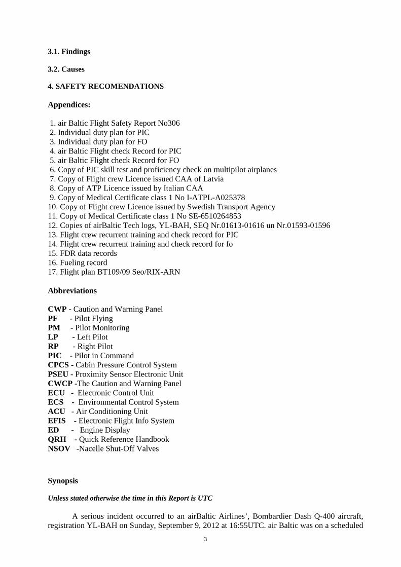
3.1. Findings 3.2. Causes 4. SAFETY RECOMENDATIONS Appendices: 1. air Baltic Flight Safety Report No306 2. Individual duty plan for PIC 3. Individual duty plan for FO 4. air Baltic Flight check Record for PIC 5. air Baltic Flight check Record for FO 6. Copy of PIC skill test and proficiency check on multipilot airplanes 7. Copy of Flight crew Licence issued CAA of Latvia 8. Copy of ATP Licence issued by Italian CAA 9. Copy of Medical Certificate class 1 No I-ATPL-A025378 10. Copy of Flight crew Licence issued by Swedish Transport Agency 11. Copy of Medical Certificate class 1 No SE-6510264853 12. Copies of airBaltic Tech logs, YL-BAH, SEQ Nr.01613-01616 un Nr.01593-01596 13. Flight crew recurrent training and check record for PIC 14. Flight crew recurrent training and check record for fo 15. FDR data records 16. Fueling record 17. Flight plan BT109/09 Seo/RIX-ARN Abbreviations CWP - Caution and Warning Panel PF - Pilot Flying PM - Pilot Monitoring LP - Left Pilot RP - Right Pilot PIC - Pilot in Command CPCS - Cabin Pressure Control System PSEU - Proximity Sensor Electronic Unit CWCP -The Caution and Warning Panel ECU - Electronic Control Unit ECS - Environmental Control System ACU - Air Conditioning Unit EFIS - Electronic Flight Info System ED - Engine Display QRH - Quick Reference Handbook NSOV -Nacelle Shut-Off Valves
Synopsis Unless stated otherwise the time in this Report is UTC
A serious incident occurred to an airBaltic Airlines’, Bombardier Dash Q-400 aircraft, registration YL-BAH on Sunday, September 9, 2012 at 16:55UTC. air Baltic was on a scheduled
4
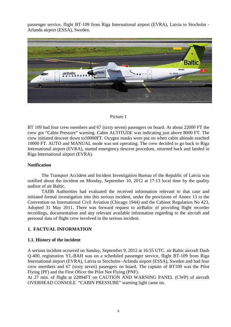
passenger service, flight BT-109 from Riga International airport (EVRA), Latvia to Stocholm -Arlanda airport (ESSA), Sweden.
Picture 1 BT 109 had four crew members and 67 (sixty seven) pasengers on board. At about 22000 FT the crew got “Cabin Pressure” warning. Cabin ALTITUDE was indicating just above 8000 FT. The crew initiated descent down to10000FT. Oxygen masks were put on when cabin altitude reached 10000 FT. AUTO and MANUAL mode was not operating. The crew decided to go back to Riga International airport (EVRA), started emergency descent procedure, returned back and landed in Riga International airport (EVRA).
Notification
The Transport Accident and Incident Investigation Bureau of the Republic of Latvia was notified about the incident on Monday, September 10, 2012 at 17:13 local time by the quality auditor of air Baltic.
TAIIB Authorities had evaluated the received information relevant to that case and initiated formal investigation into this serious incident, under the provisions of Annex 13 to the Convention on International Civil Aviation (Chicago 1944) and the Cabinet Regulation No 423, Adopted 31 May 2011. There was forward request to airBaltic of providing flight recorder recordings, documentation and any relevant available information regarding to the aircraft and personal data of flight crew involved in the serious incident. 1. FACTUAL INFORMATION 1.1. History of the incident A serious incident occurred on Sunday, September 9, 2012 at 16:55 UTC. air Baltic aircraft Dash Q-400, registration YL-BAH was on a scheduled passenger service, flight BT-109 from Riga International airport (EVRA), Latvia to Stocholm -Arlanda airport (ESSA), Sweden and had four crew members and 67 (sixty seven) pasengers on board. The captain of BT109 was the Pilot Flying (PF) and the First Oficer the Pilot Not Flying (PNF). At 27 min. of flight at 22894FT on CAUTION AND WARNING PANEL (CWP) of aircraft OVERHEAD CONSOLE “CABIN PRESSURE” warning light came on.
5
+
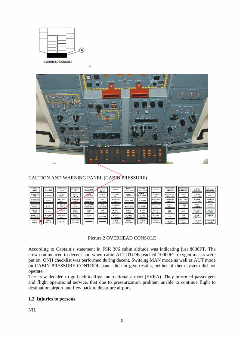
CAUTION AND WARNING PANEL (CABIN PRESSURE)
Picture 2 OVERHEAD CONSOLE According to Captain’s statement in FSR 306 cabin altitude was indicating just 8000FT. The crew commenced to decent and when cabin ALTITUDE reached 10000FT oxygen masks were put on. QNH checklist was performed during decent. Switcing MAN mode as well as AUT mode on CABIN PRESSURE CONTROL panel did not give results, neither of them system did not operate. The crew decided to go back to Riga International airport (EVRA). They informed passengers and flight operational service, that due to pressurization problem unable to continue flight to destination airport and flew back to departure airport. 1.2. Injuries to persons
NIL.
6
1.3. Damage to aircraft NIL. 1.4. Other damage NIL. 1.5. Personnel information PIC: male, 47 years old; Ratings: All necessary ratings were valid; Total flight experience - 7121 hrs; Flying experience as captain (PIC)- 6756 hrs; Flight experience on aircraft DHC8-Q400-1147 hrs; Flight time last 24 hours 06:59 BH (block hours); Flight time last 7 days -15:53BH (block hours), (period 02SEP-08SEP); Flaying hours last 28 days – 53:53 BH, (period 12AUG-08SEP). FO: male, 32 years old; Ratings: All necessary ratings were valid; Total flight experience -4872 hrs; Flight experience on aircraft DHC8-Q400-991 hrs; Flight time last 24 hours 03:33 BH (block hours); Flight time last 7 days -08:08BH (block hours), (period 02SEP-08SEP); Flaying hours last 28 days – 57:17 BH, (period 12AUG-08SEP). Rest time before flight BT109: PIC -26:15hrs FO -27:50hrs Resrt time last 48 hrs: PIC had 2 days off on 06-07 SEP, 09 SEP was his 2nd working day after days off. 1.6. AIRCRAFT INFORMATION Aircraft type - DHC8-Q402; Registration - YL-BAH; serial No. 4296; TOW – 29574 kg; Owner of aircraft -„Air Baltic Corporation”; Engines – No1 PCE-FA0654 TSN 5951:07 CSN 4271 TSR 5951:07 CSR 4271; No2 PCE-FA0655TSN 5951:07 CSN 4271 TSR 5951:07 CSR 4271;
7
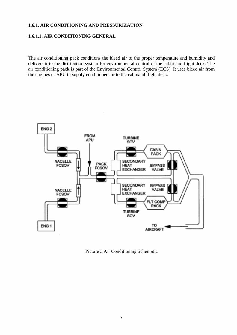
1.6.1. AIR CONDITIONING AND PRESSURIZATION 1.6.1.1. AIR CONDITIONING GENERAL The air conditioning pack conditions the bleed air to the proper temperature and humidity and delivers it to the distribution system for environmental control of the cabin and flight deck. The air conditioning pack is part of the Environmental Control System (ECS). It uses bleed air from the engines or APU to supply conditioned air to the cabinand flight deck.
Picture 3 Air Conditioning Schematic

8
The air conditioning system receives bleed air when the BLEED switches 1 and 2 on the AIR CONDITIONING control panel are selected in position “BLEED”.
Picture 4 Air conditioning control panel diagram
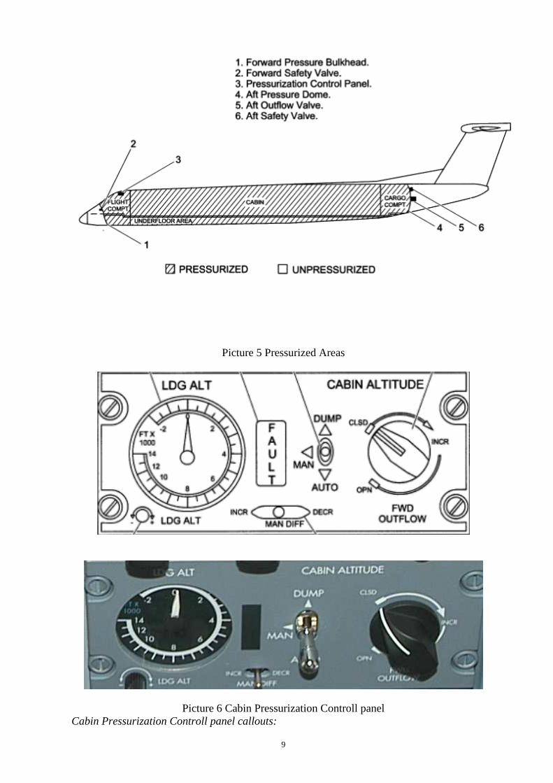
The air conditioning system is controlled by selecting the CABIN and FLT COMP PACKS switches to the MAN or AUTO positions, and then adjusting the temperature using the TEMP CONTROL knobs. These switch settings determine the bleed air source, manual or automatic Environmental Control System (ECS) operation, and the air flow temperatures for the flight and passenger compartments. The ECS Electronic Control Unit (ECU) controls the two Nacelle Shut-Off Valves (NSOV). The ECU also uses this data to control bleed airflow rate when APU bleed air is selected on. 1.6.1.2. PRESSURIZATION The aeroplane is pressurized by engine bleed air supplied to and distributed by the air –conditioning system. Pressure is maintained and controlled by the cabin pressure control system, which governs the rate of outflow from the pressurized areas of the aeroplane. An aft outflow valve primarily controls the outflow of air and is assisted by two safety valves. The aft outflow valve is controlled from the CABIN PRESSURE CONTROL panel on the flight deck OVERHEAD CONSOLE. There are independent controls and indicators to operate and monitor the system.The aft outflow valve and the aft safety valve are located on the aft pressure dome. A forward safety outflow valve is located on the forward pressure bulkhead. If cabin altitude is too high, a flight deck warning light comes on.
9
Picture 5 Pressurized Areas
Picture 6 Cabin Pressurization Controll panel Cabin Pressurization Controll panel callouts:
10
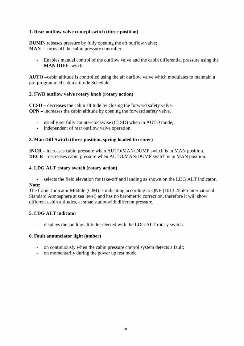
1. Rear outflow valve contrpl switch (three position) DUMP- releases pressure by fully opening the aft outflow valve; MAN - turns off the cabin pressure controller.
- Enables manual control of the outflow valve and the cabin differential pressure using the MAN DIFF switch.
AUTO –cabin altitude is controlled using the aft outflow valve which modulates to maintain a pre-programmed cabin altitude Schedule. 2. FWD outflow valve rotary knob (rotary action) CLSD – decreases the cabin altitude by closing the forward safety valve. OPN – increases the cabin altitude by opening the forward safety valve.
- usually set fully counterclockwise (CLSD) when in AUTO mode; - independent of rear outflow valve operation.
3. Man Diff Switch (three position, spring loaded to center) INCR – increases cabin pressure when AUTO/MAN/DUMP switch is in MAN position. DECR – decreases cabin pressure when AUTO/MAN/DUMP switch is in MAN position. 4. LDG ALT rotary switch (rotary action)
- selects the field elevation for take-off and landing as shown on the LDG ALT indicator. Note: The Cabin Indicator Module (CIM) is indicating according to QNE (1013.25hPa International Standard Atmosphere at sea level) and has no barometric correction, therefore it will show different cabin altitudes, at smae stationwith different pressure. 5. LDG ALT indicator
- displays the landing altitude selected with the LDG ALT rotary switch. 6. Fault annunciator light (amber)
- on continuously when the cabin pressure control system detects a fault; - on momentarily during the power up test mode.
11
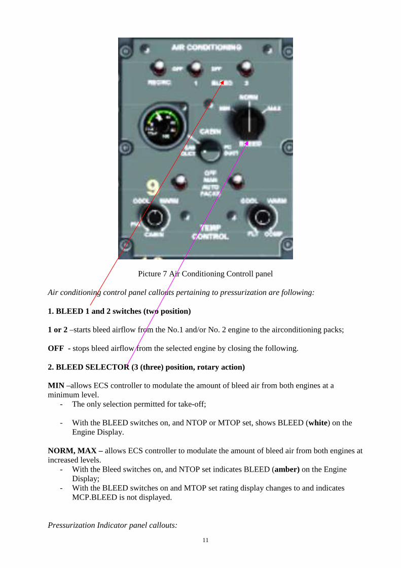
Picture 7 Air Conditioning Controll panel
Air conditioning control panel callouts pertaining to pressurization are following: 1. BLEED 1 and 2 switches (two position) 1 or 2 –starts bleed airflow from the No.1 and/or No. 2 engine to the airconditioning packs; OFF - stops bleed airflow from the selected engine by closing the following. 2. BLEED SELECTOR (3 (three) position, rotary action) MIN –allows ECS controller to modulate the amount of bleed air from both engines at a minimum level.
- The only selection permitted for take-off; - With the BLEED switches on, and NTOP or MTOP set, shows BLEED (white) on the
Engine Display. NORM, MAX – allows ECS controller to modulate the amount of bleed air from both engines at increased levels.
- With the Bleed switches on, and NTOP set indicates BLEED (amber) on the Engine Display;
- With the BLEED switches on and MTOP set rating display changes to and indicates MCP.BLEED is not displayed.
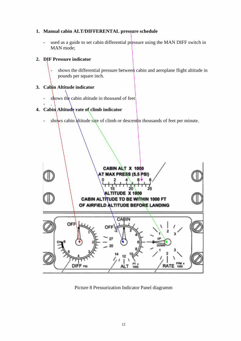
Pressurization Indicator panel callouts:
12
1. Manual cabin ALT/DIFFERENTAL pressure schedule
- used as a guide to set cabin differential pressure using the MAN DIFF switch in MAN mode;
2. DIF Pressure indicator
- shows the differential pressure between cabin and aeroplane flight altitude in pounds per square inch.
3. Cabin Altitude indicator
- shows the cabin altitude in thousand of feet - .
4. Cabin Altitude rate of climb indicator
- shows cabin altitude rate of climb or descentin thousands of feet per minute.
Picture 8 Pressurization Indicator Panel diagramm
13
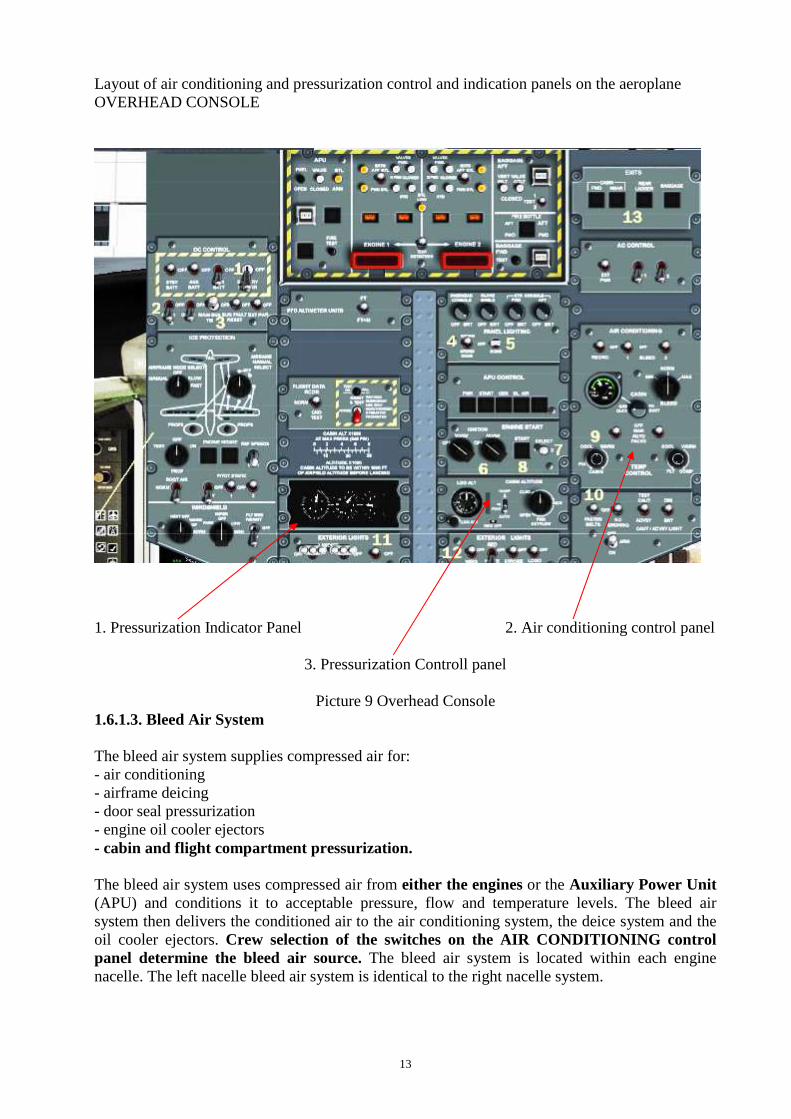
Layout of air conditioning and pressurization control and indication panels on the aeroplane OVERHEAD CONSOLE
1. Pressurization Indicator Panel 2. Air conditioning control panel
3. Pressurization Controll panel
Picture 9 Overhead Console
1.6.1.3. Bleed Air System The bleed air system supplies compressed air for: - air conditioning - airframe deicing - door seal pressurization - engine oil cooler ejectors - cabin and flight compartment pressurization. The bleed air system uses compressed air from either the engines or the Auxiliary Power Unit (APU) and conditions it to acceptable pressure, flow and temperature levels. The bleed air system then delivers the conditioned air to the air conditioning system, the deice system and the oil cooler ejectors. Crew selection of the switches on the AIR CONDITIONING control panel determine the bleed air source. The bleed air system is located within each engine nacelle. The left nacelle bleed air system is identical to the right nacelle system.
14
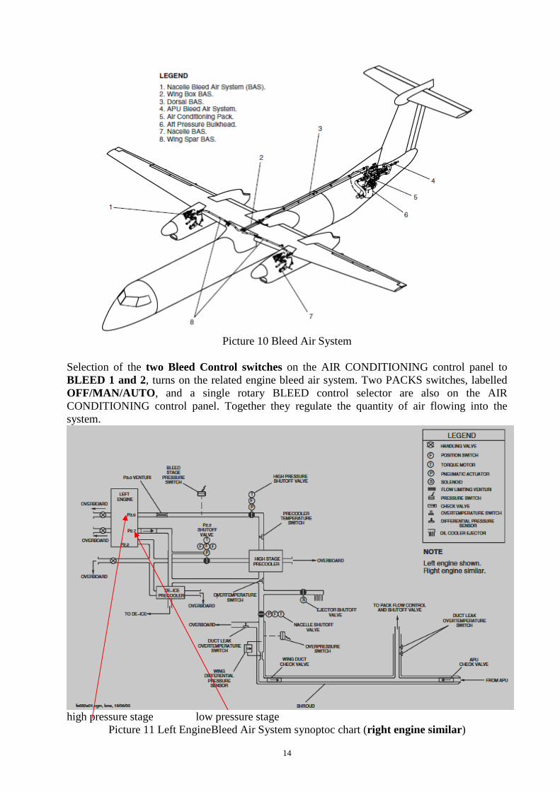
Picture 10 Bleed Air System
Selection of the two Bleed Control switches on the AIR CONDITIONING control panel to BLEED 1 and 2, turns on the related engine bleed air system. Two PACKS switches, labelled OFF/MAN/AUTO , and a single rotary BLEED control selector are also on the AIR CONDITIONING control panel. Together they regulate the quantity of air flowing into the system.
high pressure stage low pressure stage
Picture 11 Left EngineBleed Air System synoptoc chart (right engine similar)
15
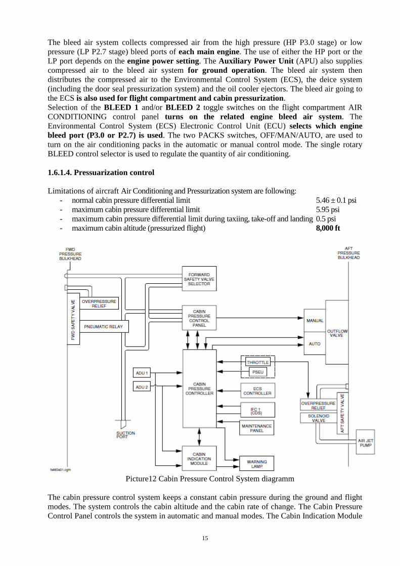
The bleed air system collects compressed air from the high pressure (HP P3.0 stage) or low pressure (LP P2.7 stage) bleed ports of each main engine. The use of either the HP port or the LP port depends on the engine power setting. The Auxiliary Power Unit (APU) also supplies compressed air to the bleed air system for ground operation. The bleed air system then distributes the compressed air to the Environmental Control System (ECS), the deice system (including the door seal pressurization system) and the oil cooler ejectors. The bleed air going to the ECS is also used for flight compartment and cabin pressurization . Selection of the BLEED 1 and/or BLEED 2 toggle switches on the flight compartment AIR CONDITIONING control panel turns on the related engine bleed air system. The Environmental Control System (ECS) Electronic Control Unit (ECU) selects which engine bleed port (P3.0 or P2.7) is used. The two PACKS switches, OFF/MAN/AUTO, are used to turn on the air conditioning packs in the automatic or manual control mode. The single rotary BLEED control selector is used to regulate the quantity of air conditioning. 1.6.1.4. Pressuarization control Limitations of aircraft Air Conditioning and Pressurization system are following:
- normal cabin pressure differential limit 5.46 ± 0.1 psi - maximum cabin pressure differential limit 5.95 psi - maximum cabin pressure differential limit during taxiing, take-off and landing 0.5 psi - maximum cabin altitude (pressurized flight) 8,000 ft
Picture12 Cabin Pressure Control System diagramm The cabin pressure control system keeps a constant cabin pressure during the ground and flight modes. The system controls the cabin altitude and the cabin rate of change. The Cabin Pressure Control Panel controls the system in automatic and manual modes. The Cabin Indication Module
16
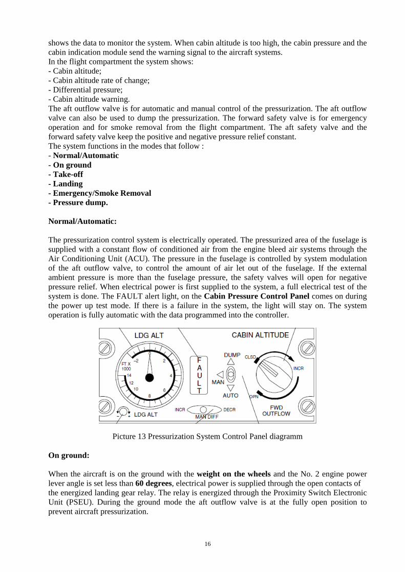
shows the data to monitor the system. When cabin altitude is too high, the cabin pressure and the cabin indication module send the warning signal to the aircraft systems. In the flight compartment the system shows: - Cabin altitude; - Cabin altitude rate of change; - Differential pressure; - Cabin altitude warning. The aft outflow valve is for automatic and manual control of the pressurization. The aft outflow valve can also be used to dump the pressurization. The forward safety valve is for emergency operation and for smoke removal from the flight compartment. The aft safety valve and the forward safety valve keep the positive and negative pressure relief constant. The system functions in the modes that follow : - Normal/Automatic - On ground - Take-off - Landing - Emergency/Smoke Removal - Pressure dump. Normal/Automatic: The pressurization control system is electrically operated. The pressurized area of the fuselage is supplied with a constant flow of conditioned air from the engine bleed air systems through the Air Conditioning Unit (ACU). The pressure in the fuselage is controlled by system modulation of the aft outflow valve, to control the amount of air let out of the fuselage. If the external ambient pressure is more than the fuselage pressure, the safety valves will open for negative pressure relief. When electrical power is first supplied to the system, a full electrical test of the system is done. The FAULT alert light, on the Cabin Pressure Control Panel comes on during the power up test mode. If there is a failure in the system, the light will stay on. The system operation is fully automatic with the data programmed into the controller.
Picture 13 Pressurization System Control Panel diagramm On ground: When the aircraft is on the ground with the weight on the wheels and the No. 2 engine power lever angle is set less than 60 degrees, electrical power is supplied through the open contacts of the energized landing gear relay. The relay is energized through the Proximity Switch Electronic Unit (PSEU). During the ground mode the aft outflow valve is at the fully open position to prevent aircraft pressurization.
17
Take-off: When the No. 2 engine power lever angle is set to greater than 60 degrees the controller sends a signal to the aft outflow valve to open or close, as necessary, to pressurize the aircraft to 400 ft (121.9 m) less than ambient. The aft outflow valve moves from the fully open position and starts to modulate to control the pressure changes that occur after take-off. When the landing gear relay is de-energized after take-off (through the PSEU), the aft outflow valve modulates to keep the set aircraft pressure. The CABIN PRESS warning light on the Caution and Warning panel comes on when the cabin altitude reaches 10,000 ft (3048 m), except when take-off or landing altitude is above 8000 ft (2438.4 m). For take-off or landing altitudes above 8000 ft (2438.4 m) the warning light will come on in the conditions that follow:
- The aircraft take-off altitude + 1000 ft (304.8 m) - Landing altitude + 1000 ft (304.8 m)
Landing: The aircraft depressurization is controlled automatically. If the set field altitude is higher than actual field altitude, the aircraft will land unpressurized. If the field altitude is set less than actual field altitude, the aircraft will land pressurized. On landing, cabin altitude will go back to field altitude at the rate programmed into the controller, for one minute before cabin pressure is bled to ambient. Manual: The manual mode is used if the automatic pressurization mode does not operate. Pressurization can be controlled through the aft outflow valve, when the AUTO-MAN-DUMP switch is set to MAN . The cabin pressure is set with the toggle switch moved and held to the DECR position, to open the aft outflow valve and increase the cabin altitude. When the toggle switch is moved and held to INCR, the aft outflow valve closes and the cabin altitude decreases. 1.7. Meteorological information NIL 1.8. Aids to Navigation NIL 1.9. Communications NIL 1.10. Aerodrome information NIL
18
1.11. Flight recorders
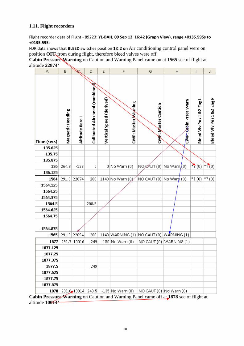
Flight recorder data of Flight - 89223: YL-BAH, 09 Sep 12 16:42 (Graph View), range +0135.595s to
+0135.595s
FDR data shows that BLEED switches position 1& 2 on Air conditioning control panel were on position OFF from during flight, therefore bleed valves were off. Cabin Pressure Warning on Caution and Warning Panel came on at 1565 sec of flight at altitude 22874’
Cabin Pressure Warning on Caution and Warning Panel came off at 1878 sec of flight at altitude 10014’
19
1.12. Wreckage and impact information Not damage 1.13. Medical and pathological information NIL 1.14. Fire There was no fire 1.15. Survival aspects NIL 1.16. Tests and research NIL 1.17. Organizational and management information NIL 1.18. Additional information NIL 1.19. Useful or effective investigation techniques NIL
20
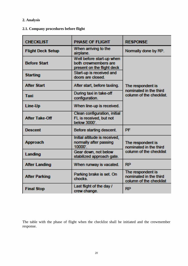
2. Analysis 2.1. Company procedures before flight
The table with the phase of flight when the checklist shall be initiated and the crewmember response.
21
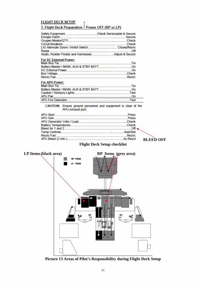
BLEED OFF Flight Deck Setup checklist
LP Items (black area) RP Items (grey area)
Picture 13 Areas of Pilot’s Responsibility during Flight Deck Setup
22
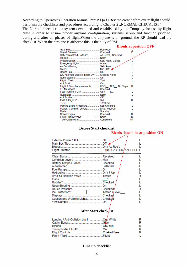
According to Operator’s Operation Manual Part B Q400 Rev the crew before every flight should performn the checklists and procedures according to Chapter 2 „NORMAL CHECKLIST” The Normal checklist is a system developed and established by the Company for use by flight crew in order to ensure proper airplane configuration, systems set-up and function prior to, during and after all phases of flight.When the airplane is on ground, the RP should read the checklist. When the airplane is airborne this is the duty of PM. Bleeds at position OFF
Before Start checklist Bleeds should be at position ON
After Start checklist
Line up checklist
23
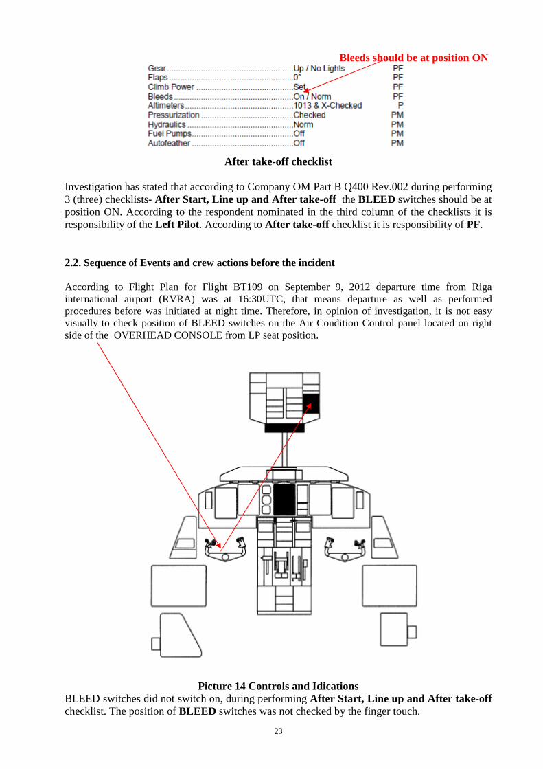
Bleeds should be at position ON
After take-off checklist
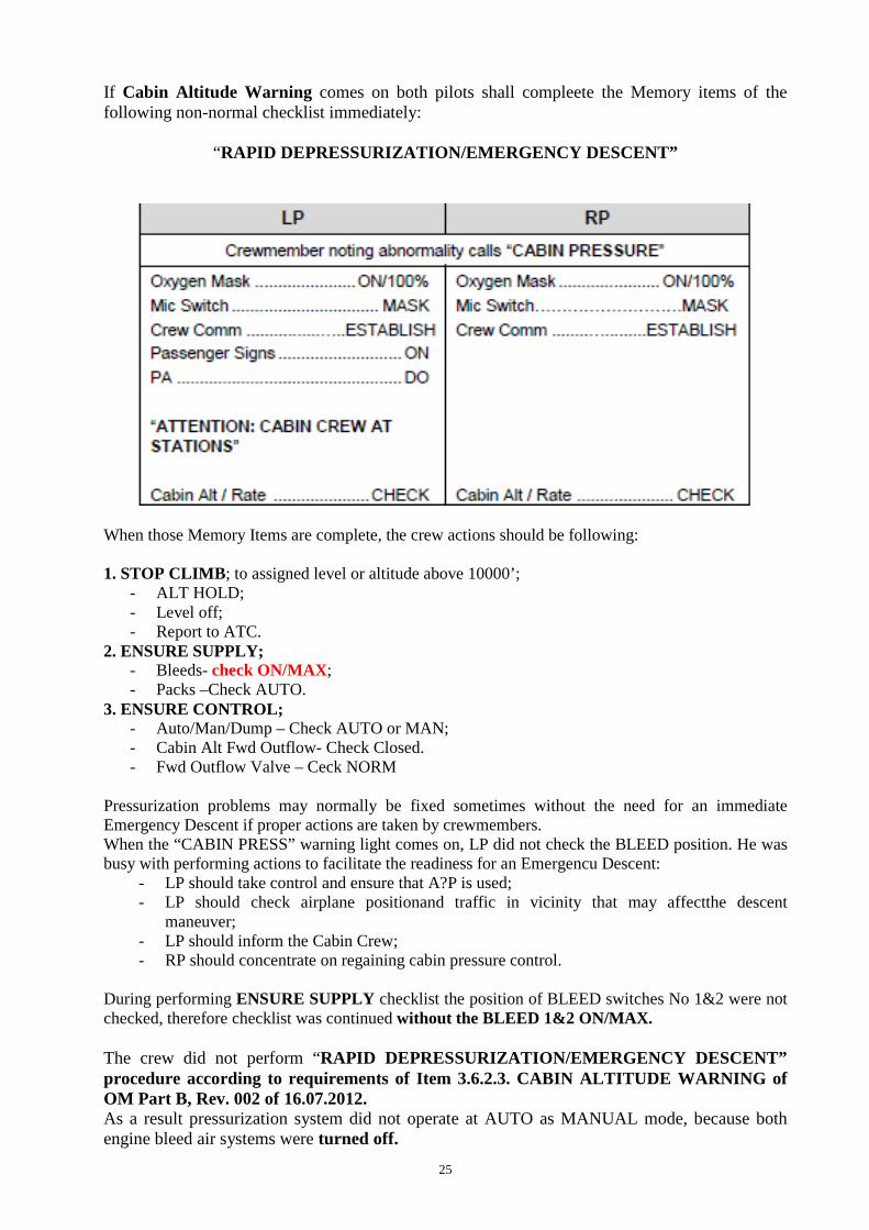
Investigation has stated that according to Company OM Part B Q400 Rev.002 during performing 3 (three) checklists- After Start, Line up and After take-off the BLEED switches should be at position ON. According to the respondent nominated in the third column of the checklists it is responsibility of the Left Pilot . According to After take-off checklist it is responsibility of PF. 2.2. Sequence of Events and crew actions before the incident According to Flight Plan for Flight BT109 on September 9, 2012 departure time from Riga international airport (RVRA) was at 16:30UTC, that means departure as well as performed procedures before was initiated at night time. Therefore, in opinion of investigation, it is not easy visually to check position of BLEED switches on the Air Condition Control panel located on right side of the OVERHEAD CONSOLE from LP seat position.
Picture 14 Controls and Idications BLEED switches did not switch on, during performing After Start, Line up and After take-off checklist. The position of BLEED switches was not checked by the finger touch.

24
In opinion of investigation the checklists according to Chapter 2 of OM Part B 400, Rev 2 were performed carelesly by LP of crew. PF is responsible of performing after take-off checklist. PF after take-off was LP – Captain of aeroplane.
2.3. Company Abnormal and Emergency Procedures. Abnormal/ Emergency Procedure- A procedure which shall be applied if a warning is received or when appropriate conditions dictates. Memory Items- Minimal vital actions, which shall be done as soon as the situation permits without reference to the checklist. Non-Normal checklist – Abnormal or Emergency Procedures for which specific checklists are developed. Could ne applied directly when in a nonnormal situation and/or upon warning have been received. 2.3.1. Responsibility of the crew members during an abnormal or emergency situation. Commander:
- Set/change the priorities/course of actions; - Identify/confirm the applicableprocedure/non normal checklist’ - Brief crewmembers and coordinate their actions; - Direct and follow the procedure.
PF:
- Control/navigate the airplane; - Initiate identified procedure/checklist; - Monitor PM’s actions.
PM:
- Carry out identified procedure/checklist; - Monitor and support PF’s actions.
2.3.2. Emergency Descent
When unpressurized the airplane must be maintained at 10 000' feet or at the lowest safe altitude, if higher. Prolonged flight at altitudes above 14 000' shall be avoided and every opportunity shall be used, including re-routing, to descent below the above- mentioned altitudes as soon as practicable.
Flight crew shall use OXYGEN when Cabin Altitude is above 10 000' with or without Cabin Altitude warning.
Emergency (Rapid) Descent could be initiated when:
- Cabin pressure cannot be controlled when the aeroplane is above 14000’;
- A rapid descent is required. 2.3.2.1. Crew actions and coordination
25
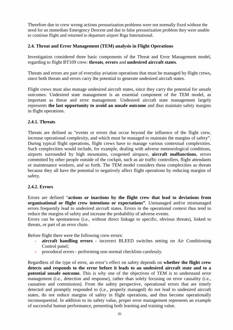
If Cabin Altitude Warning comes on both pilots shall compleete the Memory items of the following non-normal checklist immediately:
“RAPID DEPRESSURIZATION/EMERGENCY DESCENT”
When those Memory Items are complete, the crew actions should be following: 1. STOP CLIMB; to assigned level or altitude above 10000’;
- ALT HOLD; - Level off; - Report to ATC.
2. ENSURE SUPPLY; - Bleeds- check ON/MAX; - Packs –Check AUTO.
3. ENSURE CONTROL; - Auto/Man/Dump – Check AUTO or MAN; - Cabin Alt Fwd Outflow- Check Closed. - Fwd Outflow Valve – Ceck NORM
Pressurization problems may normally be fixed sometimes without the need for an immediate Emergency Descent if proper actions are taken by crewmembers. When the “CABIN PRESS” warning light comes on, LP did not check the BLEED position. He was busy with performing actions to facilitate the readiness for an Emergencu Descent:
- LP should take control and ensure that A?P is used; - LP should check airplane positionand traffic in vicinity that may affectthe descent
maneuver; - LP should inform the Cabin Crew; - RP should concentrate on regaining cabin pressure control.
During performing ENSURE SUPPLY checklist the position of BLEED switches No 1&2 were not checked, therefore checklist was continued without the BLEED 1&2 ON/MAX. The crew did not perform “RAPID DEPRESSURIZATION/EMERGENCY DESCENT” procedure according to requirements of Item 3.6.2.3. CABIN ALTITUDE WARNING of OM Part B, Rev. 002 of 16.07.2012. As a result pressurization system did not operate at AUTO as MANUAL mode, because both engine bleed air systems were turned off.
26
Therefore due to crew wrong actions pressurization problems were not normally fixed without the need for an immediate Emergency Descent and due to false pressurization problem they were unable to continue flight and returned to departure airport Riga International. 2.4. Threat and Error Management (TEM) analysis in Flight Operations Investigation considered three basic components of the Threat and Error Management model, regarding to flight BT109 crew: threats, errors and undesired aircraft states. Threats and errors are part of everyday aviation operations that must be managed by flight crews, since both threats and errors carry the potential to generate undesired aircraft states. Flight crews must also manage undesired aircraft states, since they carry the potential for unsafe outcomes. Undesired state management is an essential component of the TEM model, as important as threat and error management. Undesired aircraft state management largely represents the last opportunity to avoid an unsafe outcome and thus maintain safety margins in flight operations. 2.4.1. Threats Threats are defined as “events or errors that occur beyond the influence of the flight crew, increase operational complexity, and which must be managed to maintain the margins of safety”. During typical flight operations, flight crews have to manage various contextual complexities. Such complexities would include, for example, dealing with adverse meteorological conditions, airports surrounded by high mountains, congested airspace, aircraft malfunctions , errors committed by other people outside of the cockpit, such as air traffic controllers, flight attendants or maintenance workers, and so forth. The TEM model considers these complexities as threats because they all have the potential to negatively affect flight operations by reducing margins of safety. 2.4.2. Errors Errors are defined “actions or inactions by the flight crew that lead to deviations from organisational or flight crew intentions or expectations” . Unmanaged and/or mismanaged errors frequently lead to undesired aircraft states. Errors in the operational context thus tend to reduce the margins of safety and increase the probability of adverse events. Errors can be spontaneous (i.e., without direct linkage to specific, obvious threats), linked to threats, or part of an error chain. Before flight there were the following crew errors:
- aircraft handling errors - incorrect BLEED switches setting on Air Conditioning Control panel;
- procedural errors - performing non normal checklists carelessly. Regardless of the type of error, an error’s effect on safety depends on whether the flight crew detects and responds to the error before it leads to an undesired aircraft state and to a potential unsafe outcome. This is why one of the objectives of TEM is to understand error management (i.e., detection and response), rather than solely focusing on error causality (i.e., causation and commission). From the safety perspective, operational errors that are timely detected and promptly responded to (i.e., properly managed) do not lead to undesired aircraft states, do not reduce margins of safety in flight operations, and thus become operationally inconsequential. In addition to its safety value, proper error management represents an example of successful human performance, presenting both learning and training value.
27
During flight BT109 the crew did not detect timely error, performing non normal checlist when warning „CABIN PRESS” came on and therefore it lead to undesired aircraft state and as a result to emergency decent and returning back to deperture airport. 2.4.3. Undesired Aircraft States Undesired aircraft states are defined as ‘flight crew-induced aircraft position or speed deviations, misapplication of flight controls, or incorrect systems configuration, associated with a reduction in margins of safety”. Undesired aircraft states that result from ineffective threat and/or error management may lead to compromising situations and reduce margins of safety in flight operations. Often considered at the cusp of becoming an incident or accident, undesired aircraft states must be managed by flight crews. Events such as equipment malfunctions can also reduce margins of safety in flight operations, but these would be considered threats. Undesired states can be managed effectively, restoring margins of safety, or flight crew response(s) can induce an additional error, incident, or accident. 2.4.3.1. Incorrect systems configuration
An important learning and training point for flight crews is the timely switching from error management to undesired aircraft state management. For example if a flight crew selects a wrong BLEED switches settings and the flight crew subsequently identifies the error during a performing non- normal checklist when warning „CABIN PRESS” came on.
The use of the TEM model assists in educating flight crews that, when the aircraft is in an undesired state, the basic task of the flight crew is undesired aircraft state management instead of error management.
The training and remedial implications of this differentiation are of significance. While at the undesired aircraft state stage, the flight crew has the possibility, through appropriate TEM, of recovering the situation, returning to a normal operational state, thus restoring margins of safety. Once the undesired aircraft state becomes an outcome, recovery of the situation, return to a normal operational state, and restoration of margins of safety is not possible.
Other countermeasures are more directly related to the human contribution to the safety of flight operations. These are personal strategies and tactics, individual and team countermeasures, that typically include canvassed skills, knowledge and attitudes developed by human performance training, most notably, by Crew Resource Management (CRM) training. There are basically three categories of individual and team countermeasures: Planning countermeasures: essential for managing anticipated and unexpected threats Execution countermeasures: essential for error detection and error response Review countermeasures: essential for managing the changing conditions of a flight Enhanced TEM is the product of the combined use of systemic-based and individual and team countermeasures. 3. Conclusions 3.1. Findings
- The flight crew was licensed and qualified for the flight in accordance with applicable regulations;
- The flight crew held valid medical certificates and was medically fit to operate the flight;
- The flight crew was adequately rested and their flight and duty times were in compliance with EU OPS Sub Part Q Flight and Duty Time Limitations and Rest Requirements;
28
- air Baltic OM Part B, rev 002 was approved by SVP Flight Operations and effective from 16.07.2013;
- Procedures of OM Part B Q400 Rev 002 were adequate for performing task before flight
and during incident;
- Pilot flying during flight BT109 was Captain;
- Pilots used oxygen masks and initiated emergency descent procedure;
- 3 (three) checklists- After Start, Line up and After take-off were performed carelesly by the crew mwmbers, without actual switching knob checking on pressurization control and indication panels;
- FDR data shows that BLEED switches position 1& 2 on Air conditioning control panel were on
position OFF during all flight , therefore both engine bleed air systems were turned off;
- the bleed airflow sources- both main engine bleed air systems which distribute the compressed air to the Environmental Control System and is also used for flight compartment and cabin pressurization were switched off;
- According to the respondent nominated in the third column of the checklists it is responsibility of the Left Pilot to check position of air BLEED switches 1&2 on Air Conditioning Control panel;
- „Cabin Pressure” warning on Caution and Warning panel came on at 1565 sec of flight at altitude 22874’
- The crew did not perform “RAPID DEPRESSURIZATION/EMERGENCY DESCENT” procedure according to requirements of Item 3.6.2.3. CABIN ALTITUDE WARNING of OM Part B, Rev. 002 of 16.07.2012;
- During flight the crew did not detect timely error, performing “RAPID
DEPRESSURIZATION/EMERGENCY DESCENT” procedure when warning „CABIN PRESS” came on.
3.2. Causes Causes of the serious incident - cabin depressurization of aircraft DHC-8-402, registered YL-BAH, flight BT109, were the following: 3.2.1. Proximate Cause The source or origin of an event that caused this incident was the fact that the Pilot in Comand did not switch BLEED switches 1&2 on the Air Conditioning Control Panel.
3.2.2. Root Cause The factor that resulted this incident was that the bleed airflow sources- both main engine bleed air systems which distribute the compressed air to the Environmental Control System and is also used for flight compartment and cabin pressurization were switched off and did not delivered flow of conditioned air through the Air Conditioning Unit (ACU).
29
3.2.3. Contributing causes Indistinguishably to check visually, without finger touch, position of BLEED switches on the Air Condition Control panel on the OVERHEAD CONSOLE from LP seat position at night time. 3.2.4. Primary cause The event after which incident became inevitable. Performing by the crew in improper manner procedure “RAPID DEPRESSURIZATION/EMERGENCY DESCENT”, when warning “CABIN PRESS” came on, not corresponding to the requirements of Item 3.6.2.3. ”CABIN ALTITUDE WARNING” of OM Part B, Rev. 002 of 16.07.2012. 4. Safety Recommendations As a result of the investigation of this accident, the Transport Accident and Incident Investigation Bureau Republic of Latvia recommends the following: Recommendation - 8-2013 Operator Air Baltic should provide incidents or serious incidents analysis where human factor elements are involved and to consider oportunity to include in the crew training programms section dedicated to human factors –unsafe acts of operators and preconditions for unsafe acts. October 18, 2012 Director of Transport Accident and Incident Investigation Bureau Ivars Alfreds Gaveika Investigator in charge – Head of Aircraft Accident and Incident Investigation Department Visvaldis Trubs
:

30

31