bombardier learjet-45 general description
DESCRIPTION
BombardierLearjet 45Aircraft SystemsBusiness jetsTRANSCRIPT
Pilot’s Manual
PM-126A I-1
TABLE OF CONTENTS
Aircraft General Description.................................................................... 1-1Airplane Three-View (Figure 1-1)........................................................ 1-2General Arrangement — Exterior (Figure 1-2).................................. 1-3
Cabin Entry Door ..................................................................................... 1-5Entry Door Annunciations ................................................................... 1-6Cabin Door Operation........................................................................... 1-8
To Open Cabin Door From the Outside......................................... 1-8Opening Cabin Door (From Outside) (Figure 1-3)....................... 1-8To Close Cabin Door From the Inside............................................ 1-9Closing Cabin Door (Lower Door From Inside) (Figure 1-4) ......................................... 1-9Closing Cabin Door (Upper Door From Inside) (Figure 1-5) ....................................... 1-10Cabin Door Closed and Latched Verification ............................. 1-11Cabin Door Latch Pin Sight Windows (Figure 1-6) ................... 1-11To Open Cabin Door From the Inside.......................................... 1-13Opening Cabin Door (From Inside) (Figure 1-7)........................ 1-13To Close Cabin Door From the Outside....................................... 1-14Closing Cabin Door (From the Outside) (Figure 1-8)................ 1-14
Emergency Exits ...................................................................................... 1-15Left Forward Emergency Exit ............................................................ 1-15Left Forward Emergency Exit Operation ......................................... 1-16Left Forward Emergency Exit Operation (Figure 1-9).................... 1-16Right Aft Emergency Exit Hatch ....................................................... 1-17Aft Emergency Exit Security Pin (Figure 1-10)................................ 1-17Right Aft Emergency Exit Hatch Operation .................................... 1-18To Open/Remove the Right Aft Emergency ExitFrom the Inside .................................................................................... 1-18Emergency Exit Hatch Operation (From Inside) (Figure 1-11) ..... 1-18To Open/Remove the Emergency Exit Hatch From the Outside ................................................................................. 1-19Emergency Exit Hatch Operation (From the Outside) (Figure 1-12) ....................................................... 1-19Installing the Right Aft Emergency Exit Hatch From the Inside .................................................................................... 1-20Right Aft Emergency Exit Annunciations........................................ 1-20
SECTION IGENERAL DESCRIPTION
Pilot’s Manual
I-2 PM-126A
TABLE OF CONTENTS (Cont)
External Doors ......................................................................................... 1-21Baggage Compartment Door............................................................. 1-21Tailcone Access Door .......................................................................... 1-21External Doors Annunciations .......................................................... 1-21External Service Doors........................................................................ 1-21
Oxygen Service Door ..................................................................... 1-21Fuselage Fuel Gravity Fill Access Door ...................................... 1-22Single-Point Pressure Refueling Access Door ............................ 1-22Single-Point Pressure Refueling Control Panel Access Door... 1-22Oil Servicing Doors ........................................................................ 1-22
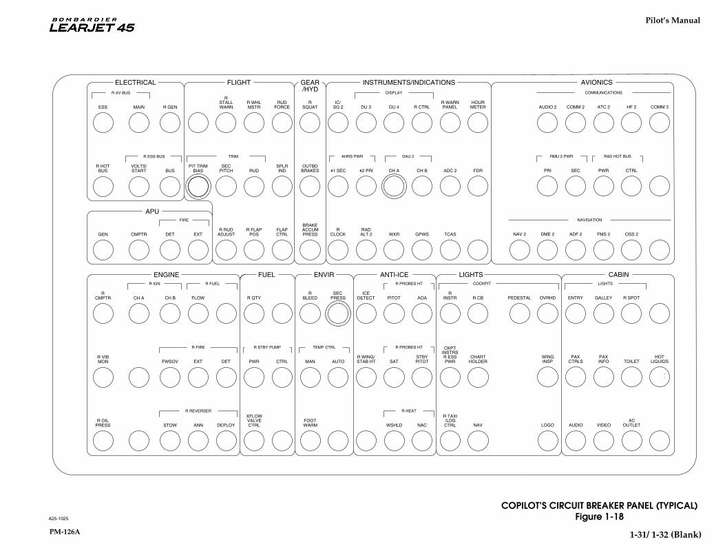
Turning Radius (Figure 1-13) ............................................................. 1-23Danger Areas (Figure 1-14) ................................................................ 1-24Instrument Panel (Typical) (Figure 1-15) ......................................... 1-25Pedestal (Typical) (Figure 1-16) ......................................................... 1-27Pilot’s Circuit Breaker Panel (Typical) (Figure 1-17) ...................... 1-29Copilot’s Circuit Breaker Panel (Typical) (Figure 1-18) ................. 1-31

Pilot’s Manual
PM-126A 1-1
AIRCRAFT GENERAL DESCRIPTION
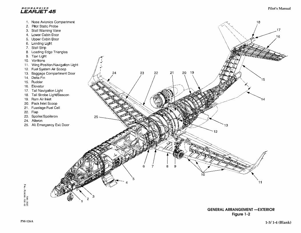
The Learjet 45 aircraft, manufactured by Learjet Inc., is an all metal,pressurized, low-wing, turbofan-powered monoplane. The high-aspectratio, fully cantilevered, swept-back wings with winglets are of conven-tional riveted construction except for the upper section of the winglets,which utilize full-depth honeycomb core bonded to the outer skin. Thefuselage is of semimonocoque construction and utilizes a constant cir-cular cross sectional shape across the upper fuselage half and an elon-gated cross sectional shape in the lower fuselage. The constant uppercircular section extends back to the aft pressure bulkhead where it isfaired into the tailcone. Two inverted “V” ventral fins (delta fins) are fit-ted to the aft section of the tailcone to provide the aircraft withfavorable stall recovery characteristics and additional lateral/directional stability.
Thrust is provided by two pod-mounted TFE-731-20 turbofan enginesmanufactured by Honeywell. Independent fuel systems supply fuel tothe engines with fuel storage provided in wing and fuselage tanks. En-gine-driven hydraulic pumps provide hydraulic power for braking, ex-tending or retracting the landing gear, wing flaps, spoilers, and thrustreversers. The landing gear system is a fully retractable tricycle-typetrailing link landing gear with dual main gear wheels, nose-wheelsteering, and a brake-by-wire brake control/anti-skid braking system.
The ailerons, rudder, and elevator are manually controlled throughcables, bellcranks, pulleys, and push-pull tubes. An electrically-actuated trim tab is installed on the left aileron and on the rudder toprovide lateral and directional trim. Longitudinal trim is accomplishedby changing the incidence of the horizontal stabilizer with anelectrically-operated linear actuator. Aircraft air conditioning systemswhich include an air cycle machine, provide heating, cooling, andpressurization for the cockpit, passenger compartment and aft lavatory.
SECTION IGENERAL DESCRIPTION

Pilot’s Manual
1-2 PM-126A
A06-0002F45-000000-101
AIRPLANE THREE-VIEWFigure 1-1
NOTE: All dimensions shownfor aircraft in static position.
58 ft 5 in(17.81 m)
9 ft 4 in(2.85 m)
47 ft 10 in(14.58 m)
54 ft 0 in(16.46 m)
17 ft 2 in(5.24 m)
14 ft 1 in(4.29 m)
Pilot’s Manual
PM-126A 1 - 11/ 1 - 12 (Blank)
GENERAL ARRANGEMENT —EXTERIORFigure 1-2
1-3/ 1-4 (Blank)

Pilot’s Manual
PM-126A 1-5
CABIN ENTRY DOOR
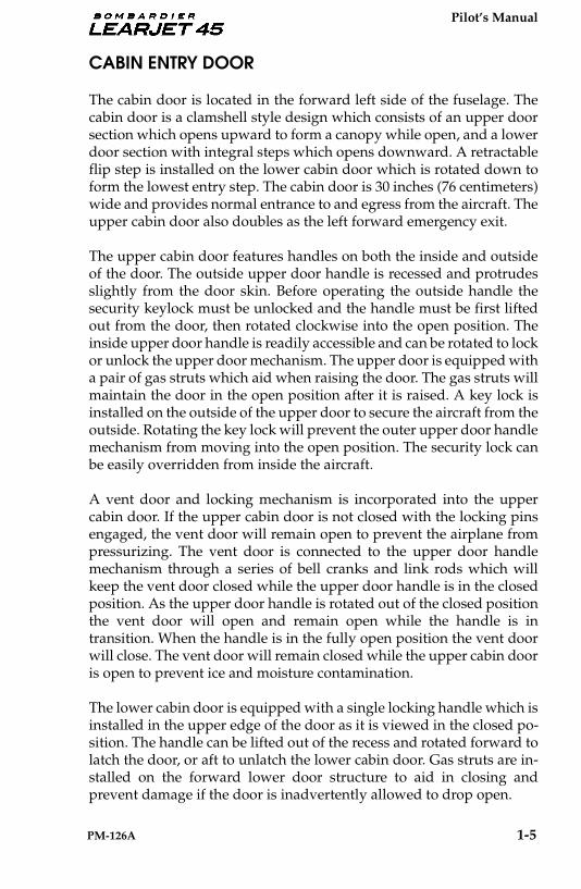
The cabin door is located in the forward left side of the fuselage. Thecabin door is a clamshell style design which consists of an upper doorsection which opens upward to form a canopy while open, and a lowerdoor section with integral steps which opens downward. A retractableflip step is installed on the lower cabin door which is rotated down toform the lowest entry step. The cabin door is 30 inches (76 centimeters)wide and provides normal entrance to and egress from the aircraft. Theupper cabin door also doubles as the left forward emergency exit.
The upper cabin door features handles on both the inside and outsideof the door. The outside upper door handle is recessed and protrudesslightly from the door skin. Before operating the outside handle thesecurity keylock must be unlocked and the handle must be first liftedout from the door, then rotated clockwise into the open position. Theinside upper door handle is readily accessible and can be rotated to lockor unlock the upper door mechanism. The upper door is equipped witha pair of gas struts which aid when raising the door. The gas struts willmaintain the door in the open position after it is raised. A key lock isinstalled on the outside of the upper door to secure the aircraft from theoutside. Rotating the key lock will prevent the outer upper door handlemechanism from moving into the open position. The security lock canbe easily overridden from inside the aircraft.
A vent door and locking mechanism is incorporated into the uppercabin door. If the upper cabin door is not closed with the locking pinsengaged, the vent door will remain open to prevent the airplane frompressurizing. The vent door is connected to the upper door handlemechanism through a series of bell cranks and link rods which willkeep the vent door closed while the upper door handle is in the closedposition. As the upper door handle is rotated out of the closed positionthe vent door will open and remain open while the handle is intransition. When the handle is in the fully open position the vent doorwill close. The vent door will remain closed while the upper cabin dooris open to prevent ice and moisture contamination.
The lower cabin door is equipped with a single locking handle which isinstalled in the upper edge of the door as it is viewed in the closed po-sition. The handle can be lifted out of the recess and rotated forward tolatch the door, or aft to unlatch the lower cabin door. Gas struts are in-stalled on the forward lower door structure to aid in closing andprevent damage if the door is inadvertently allowed to drop open.

Pilot’s Manual
1-6 PM-126A
CABIN ENTRY DOOR (CONT)
A cable and knob assembly is attached to the forward side of the lowerdoor frame.The cable and knob assembly is used to raise and lower thelower door from inside the cabin. When closing the lower cabin door, asecondary latch will automatically engage and hold the lower door inposition against the door seal until the lower door handle is rotatedforward to the locked position. If the handle is not rotated to latch thedoor and the door is left in position by the secondary latch, the upperdoor will be prevented from closing due to a pin which extends out-board from the lower door just below the handle.
When the locking handle on the lower door is rotated forward, thelatching mechanism drives four pins into the fuselage frame, securingthe lower door. The inside and outside handles on the upper cabin doorare secured to a common shaft within the door. When either upper doorhandle is rotated to the closed position, six latching pins are driven intothe fuselage structure and two pins are driven from the upper door intooverlapping halves in the lower door. There are a total of eight pinsinstalled in the upper door. Two of the six upper door latching pins aredriven through both the fuselage structure and through interlockingarms on the lower door, which secure the doors together.
When the cabin entry door pins are engaged (there are twelve pinstotal, eight in the upper door, four in the lower door), the door becomesa rigid structural member. Correct pin engagement may be checkedusing the small sight windows installed in the upper and lower innerdoor panels. Sight windows are provided to check pin engagement forten of the latch pin locations, for two middle lock pins and for the lowerlock (pawl).
ENTRY DOOR ANNUNCIATIONS
All of the twelve cabin door latching pins are installed so they contacta microswitch when the pin is fully engaged. If any of these pins do notmake contact when the upper door handle is closed, a red ENTRYDOOR warning light is displayed on the Crew Warning Panel (CWP)and a red ENTRY DOOR message on the Engine Indicating and CrewAlerting System (EICAS) illuminates to provide the crew with visualindication of cabin door security.
Pilot’s Manual
PM-126A 1-7
ENTRY DOOR ANNUNCIATIONS (Cont)
A white ENTRY DOOR PIN message will illuminate on the CASwhenever the aircraft is on the ground and the cabin door pins are notall fully engaged or all not fully disengaged. The ENTRY DOOR CWPmessage will be simultaneously displayed with the ENTRY DOOR PINCAS message. If the keylock on the upper cabin entry (forwardemergency exit) door is locked and electrical power is applied to theaircraft the red ENTRY DOOR light on the CWP will illuminate steadyto prevent operations with the emergency exit locked. The red ENTRYDOOR and white ENTRY DOOR PIN CAS messages will also bedisplayed on the EICAS when the aircraft is in this configuration.
If the DOOR circuit breaker on the pilot’s circuit breaker panel is out,the red ENTRY DOOR CWP annunciator and the red ENTRY DOORand white ENTRY DOOR PIN CAS messages will all be displayed atthe same time.
Pilot’s Manual
1-8 PM-126A
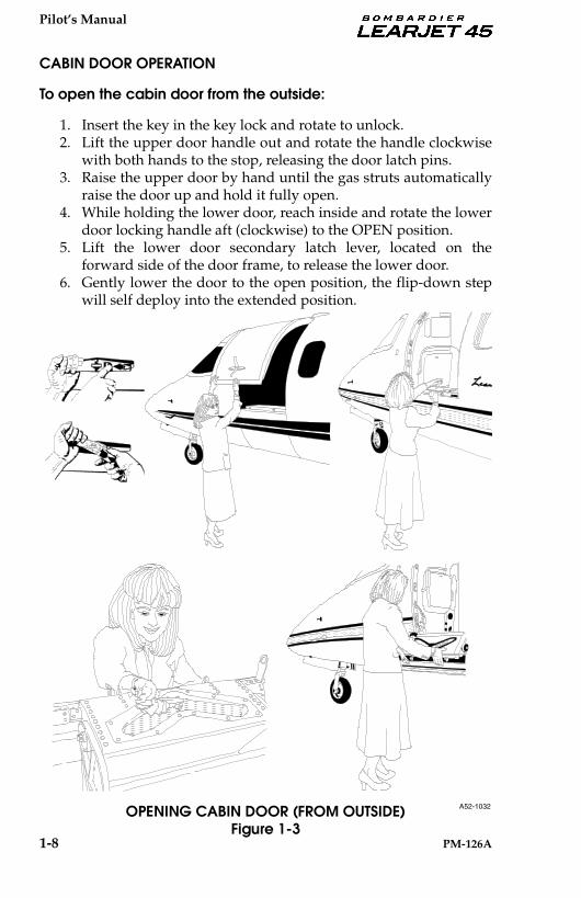
CABIN DOOR OPERATION
To open the cabin door from the outside:
1. Insert the key in the key lock and rotate to unlock. 2. Lift the upper door handle out and rotate the handle clockwise
with both hands to the stop, releasing the door latch pins.3. Raise the upper door by hand until the gas struts automatically
raise the door up and hold it fully open.4. While holding the lower door, reach inside and rotate the lower
door locking handle aft (clockwise) to the OPEN position.5. Lift the lower door secondary latch lever, located on the
forward side of the door frame, to release the lower door.6. Gently lower the door to the open position, the flip-down step
will self deploy into the extended position.
OPENING CABIN DOOR (FROM OUTSIDE)Figure 1-3
A52-1032

Pilot’s Manual
PM-126A 1-9
CABIN DOOR OPERATION (CONT)
To close cabin door from the inside:
The flip-down step could cause injury to the hand orfingers if it is allowed to suddenly swing down intothe stowed position. The flip-down step must begrasped firmly as the door is raised, and lowered byhand before the step nears the vertical position.
1. Raise the lower door using the cable and knob until the lowerdoor is within reach. Immediately grasp the flip-down step,before it falls inward and lower it by hand into the stowedposition against the inside of the lower door.
2. Pull the lower door against the door seal until the secondarylatch engages, the secondary latch will hold the door in place.Release the cable and knob and allow the cable to retract,stowing the knob on forward side of the door frame.
3. Rotate the lower door handle forward (counterclockwise) to thelocked position.
CLOSING CABIN DOOR(LOWER DOOR FROM INSIDE)
Figure 1-4
WARNING
A52-1037

Pilot’s Manual
1-10 PM-126A
CABIN DOOR OPERATION (CONT)
4. Pull the upper door down until the upper door handle is withinreach.
5. With the upper door handle in the OPEN position (with thehandle pointing up), pull the door tightly against the door sealand rotate the locking handle forward (clockwise) to the lockedposition. (If preparing for flight, check that the ENTRY DOORwarning annunciator light on the CWP is extinguished and theENTRY DOOR and ENTRY DOOR PIN messages on the CASare extinguished.)
6. Inspect the cabin door sight windows, located on the inside ofthe upper and lower door panels, to ensure that all of thelatches and locks are properly engaged. The sight windowsshould appear in the safe condition as shown in Figure 1-6CABIN DOOR LATCH PIN SIGHT WINDOWS.
CLOSING CABIN DOOR(UPPER DOOR FROM INSIDE)
Figure 1-5
A52-1037
Pilot’s Manual
PM-126A 1 - 11/ 1 - 12 (Blank)
UNSAFECONDITION
SAFECONDITION6 PLACES
SAFECONDITION2 PLACES
UNSAFECONDITION
MIDDLE LOCK PIN SIGHT WINDOWS
UNSAFECONDITION
SAFECONDITION1 PLACE
SAFECONDITION4 PLACES
UNSAFECONDITION
LOWER CABIN DOORLATCH PIN SIGHT WINDOWS
VIEW: LOOKING OUTBOARD AT THE UPPER CABIN DOOR
VIEW: LOOKING OUTBOARD AT THE LOWER CABIN DOOR
A25-1036
CABIN DOOR LATCH PIN SIGHT WINDOWSFigure 1-6
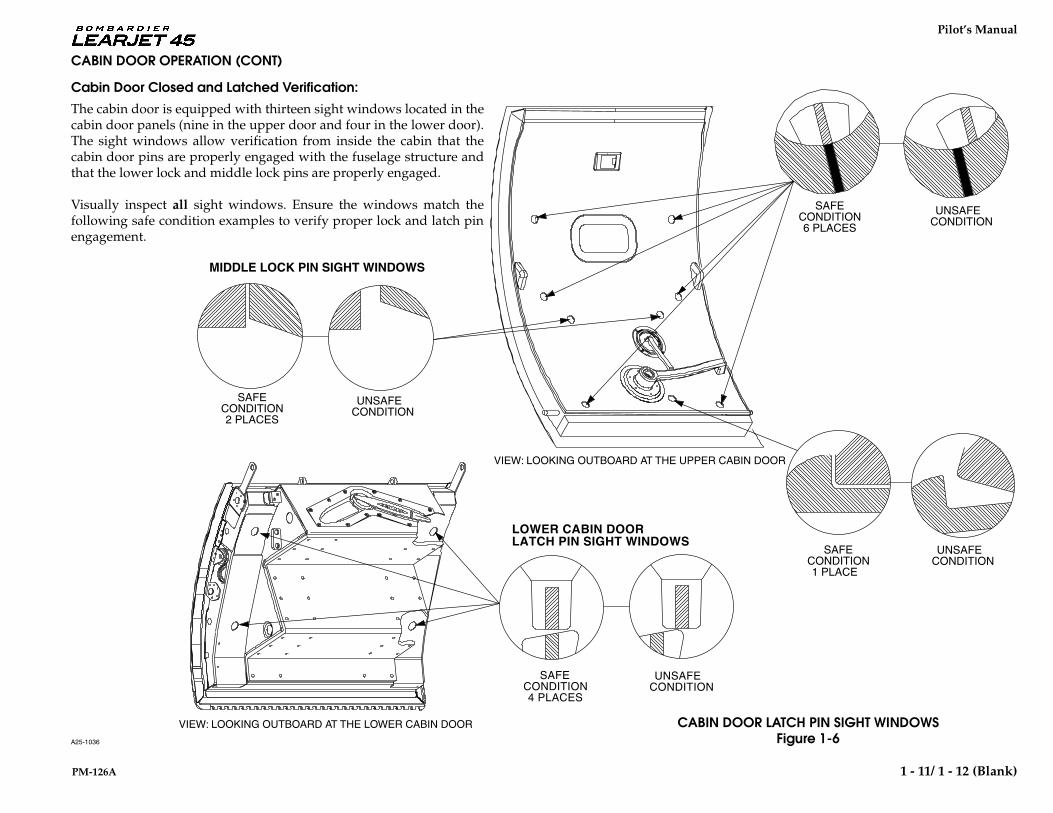
CABIN DOOR OPERATION (CONT)
Cabin Door Closed and Latched Verification:
The cabin door is equipped with thirteen sight windows located in thecabin door panels (nine in the upper door and four in the lower door).The sight windows allow verification from inside the cabin that thecabin door pins are properly engaged with the fuselage structure andthat the lower lock and middle lock pins are properly engaged.
Visually inspect all sight windows. Ensure the windows match thefollowing safe condition examples to verify proper lock and latch pinengagement.

Pilot’s Manual
PM-126A 1-13
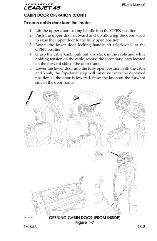
CABIN DOOR OPERATION (CONT)
To open cabin door from the inside:
1. Lift the upper door locking handle into the OPEN position. 2. Push the upper door outward and up allowing the door struts
to raise the upper door to the fully open position.3. Rotate the lower door locking handle aft (clockwise) to the
OPEN position.4. Grasp the cable knob, pull out any slack in the cable and while
holding tension on the cable, release the secondary latch locatedon the forward side of the door frame.
5. Lower the lower door into the fully open position with the cableand knob, the flip-down step will pivot out into the deployedposition as the door is lowered. Stow the knob on the forwardside of the door frame.
OPENING CABIN DOOR (FROM INSIDE)Figure 1-7
A52-1036
Pilot’s Manual
1-14 PM-126A
CABIN DOOR OPERATION (CONT)
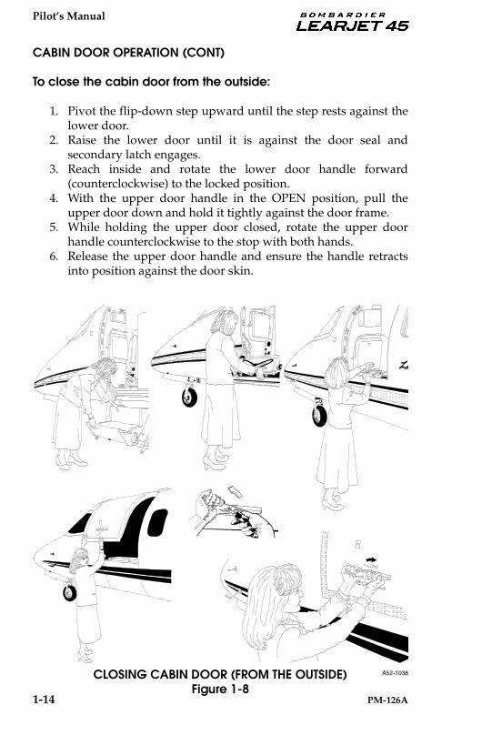
To close the cabin door from the outside:
1. Pivot the flip-down step upward until the step rests against thelower door.
2. Raise the lower door until it is against the door seal andsecondary latch engages.
3. Reach inside and rotate the lower door handle forward(counterclockwise) to the locked position.
4. With the upper door handle in the OPEN position, pull theupper door down and hold it tightly against the door frame.
5. While holding the upper door closed, rotate the upper doorhandle counterclockwise to the stop with both hands.
6. Release the upper door handle and ensure the handle retractsinto position against the door skin.
CLOSING CABIN DOOR (FROM THE OUTSIDE)Figure 1-8
A52-1038
Pilot’s Manual
PM-126A 1-15
EMERGENCY EXITS
LEFT FORWARD EMERGENCY EXIT
The upper portion of the cabin entry door serves as the left forwardemergency exit. The upper cabin entry door/left forward emergencyexit is secured to the fuselage by six latching pins which extend fromthe left forward emergency exit into the fuselage structure and by twolatching pins which are driven from the left forward emergency exitinto an overlapping section in the lower cabin entry door. The pins areextended and retracted by the upper cabin door handles (on the insideand outside of the cabin door) which operate a common shaft.
Because the upper door is equipped with a keylock, it must beunlocked before flight to ensure optimum operation as an emergencyexit. However, in the event that the keylock is locked, an override baris installed on the inside of the door, above the door handle. Whendepressed outboard, the override bar will disable the locking functionand allow the inboard handle to unlatch the left forward emergencyexit. To open the left forward emergency exit from inside, the uppercabin door handle is rotated up (counterclockwise) into the OPENposition and the upper door is pushed open. The lower cabin door iskept closed. Keeping the lower door closed will also provide a greatersafety factor in the event of ditching.
Pilot’s Manual
1-16 PM-126A
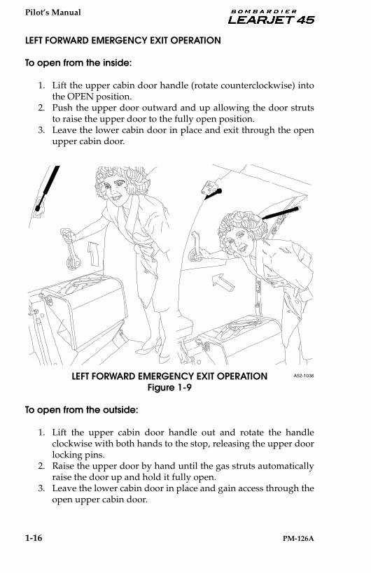
LEFT FORWARD EMERGENCY EXIT OPERATION
To open from the inside:
1. Lift the upper cabin door handle (rotate counterclockwise) intothe OPEN position.
2. Push the upper door outward and up allowing the door strutsto raise the upper door to the fully open position.
3. Leave the lower cabin door in place and exit through the openupper cabin door.
LEFT FORWARD EMERGENCY EXIT OPERATIONFigure 1-9
To open from the outside:
1. Lift the upper cabin door handle out and rotate the handleclockwise with both hands to the stop, releasing the upper doorlocking pins.
2. Raise the upper door by hand until the gas struts automaticallyraise the door up and hold it fully open.
3. Leave the lower cabin door in place and gain access through theopen upper cabin door.
A52-1036

Pilot’s Manual
PM-126A 1-17
RIGHT AFT EMERGENCY EXIT HATCH
The emergency exit hatch is located on the right aft side of the cabinnear the leading edge of the wing, adjacent to the right aft passengerseat. It provides egress from the cabin in the event of an emergency. Thehatch is secured to the airframe by two spring-loaded pins whichextend from the top of the hatch into the fuselage structure. The hatchis designed as a plug type hatch which opens inward only, and is heldin the closed position by pressurization forces and the spring loadedpins. The emergency exit hatch is 20 inches (51 centimeters) wide by 36inches (91 centimeters) high and functions as a Type III escape hatch.
A security pin can be installed on the inside of the emergency exit hatchto prevent unauthorized entry from the outside. The security pin isinserted from the inside to lock one of the spring loaded hatch pins inplace. The security pin has a small flag attached which states REMOVEBEFORE FLIGHT.
AFT EMERGENCY EXIT SECURITY PINFigure 1-10
A52-1033

Pilot’s Manual
1-18 PM-126A
RIGHT AFT EMERGENCY EXIT HATCH OPERATION
To open/remove the right aft emergency exit from the inside:
1. Remove the handle cover from the emergency exit hatch to fullyexpose the emergency exit handle. The cover is attached withhook and loop fasteners and can be easily pulled from thehatch.
2. Grasp the emergency exit handle placarded EXIT-PULL andpull it fully toward you and up, retracting the hatch pins.
3. While holding the emergency exit handle in the retractedposition, tilt the top edge of the hatch inward.
4. Grasp the hatch in the armrest recess with the opposite handand lift the hatch inward and up from the fuselage structure.
5. Lean the top of the hatch inward and rotate the hatch onto itsedge.
6. Pass the hatch through the emergency exit opening to theoutside of the aircraft.
EMERGENCY EXIT HATCH OPERATION (FROM INSIDE)Figure 1-11
EXIT-PULLEXIT-PULL
EM
ER
GE
NC
Y D
OO
RE
ME
RG
EN
CY
DO
OR
PU
SH
TO
OP
EN
PU
SH
TO
OP
EN
DO
OR
OP
EN
S IN
WA
RD
DO
OR
OP
EN
S IN
WA
RD

Pilot’s Manual
PM-126A 1-19
EMERGENCY EXIT HATCH OPERATION (CONT)
To open/remove the emergency exit hatch from the outside:
1. Locate the emergency exit hatch latch. The latch is locatedabove the window in the emergency exit door, immediatelyabove the placard that reads “EMERGENCY DOOR PUSH TOOPEN DOOR OPENS INWARD”.
2. Push fully inward on the latch. This will retract the pins into thetop of the hatch.
3. While holding the latch open, push the upper edge of the hatchinward.
4. Lift the hatch upward from the fuselage structure, inward intothe cabin.
5. Rotate the hatch onto its edge and remove it by pulling it backthrough the emergency exit opening.
EMERGENCY EXIT HATCH OPERATION (FROM OUTSIDE)Figure 1-12
A52-1039

Pilot’s Manual
1-20 PM-126A
Installing the right aft emergency exit hatch from the inside:
The emergency exit hatch is designed to be installedfrom inside the cabin only. Ensure the seat next to theemergency exit hatch is positioned in the fullyinboard position before installing the hatch.
1. Position the emergency exit hatch next to the emergency exitopening on the inside of the cabin.
2. Tilt the upper end of the emergency exit hatch down andinward (several inches).
3. Position the lower edge of the hatch so that the fittings on thelower edge of the hatch align with and engage the fittings onthe lower side of the emergency exit opening.
4. Set the hatch in place on the lower fittings and grasp theemergency exit handle and pull it fully inward and down. Thiswill retract the latch pins into the top of the hatch.
5. While keeping the latch pins retracted push the upper edge ofthe emergency exit hatch into the cabin structure (hatch frame).Ensure the emergency exit hatch seal fits into the hatch frameevenly and does not become caught or bound.
6. Release the emergency exit handle and ensure the latch pinsextend into the cabin structure. The handle is spring loaded andshould fully retract when released.
7. Attach the handle cover to the inner panel with the hook andloop fasteners.
RIGHT AFT EMERGENCY EXIT ANNUNCIATIONS
A hatch warning system microswitch is installed on one of the latchpins above the right aft emergency exit hatch frame. If this microswitchsenses that the latch pin is not in the fully extended position, the switchwill cause an amber caution EMERGENCY EXIT message to bedisplayed on the EICAS.
NOTE
Pilot’s Manual
PM-126A 1-21
EXTERNAL DOORSBAGGAGE COMPARTMENT DOOR
The baggage compartment door provides access to the baggagecompartment and is located on the left side of the fuselage below theleft engine nacelle. The door is 33 inches (84 centimeters) wide and ishinged on the forward side. The baggage door has two latches and anoptional security lock installed on the aft side. The door is equippedwith a strut and opens to the forward side for unobstructed loading.
TAILCONE ACCESS DOOR
The tailcone access door is located on the lower side of the fuselage aftof the right engine and provides access to the aft equipment bay. The aftequipment bay contains many of the electrical, environmental,hydraulic and engine fire extinguishing system components. The dooris hinged at the lower edge and is secured at the upper side with twolatches. It opens downward for access to the listed components.
EXTERNAL DOORS ANNUNCIATIONS
Illumination of the EXTERNAL DOORS amber CAS message indicatesthat either the baggage compartment door or the tailcone access doorswitches have not signaled that the door is closed. There are twoswitches on each door. The switches are designed to indicate a dooropen condition if it exists, prior to takeoff. If the doors were properlylatched prior to takeoff and the light illuminates in flight, the mostprobable cause is a switch failure.
EXTERNAL SERVICE DOORS
OXYGEN SERVICE DOOR
The nose oxygen servicing door is located on the lower right side of thenose, below the right side nose avionics access panel. The nose accessdoor is hinged at the lower edge and is secured at the upper edge withtwo latches.
On aircraft modified by SB 45-12-1 (Installation of Remote Oxygen ServicingProvisions), an optional remote mounted oxygen filler port and electri-cally-driven oxygen temperature/pressure gauge are installed behindthis service door.
If applicable, an oxygen servicing door located on the right wing rootmay also be installed. An oxygen filler port and electrically-driven ox-ygen temperature/pressure gauge are installed behind this servicedoor. The door is hinged on the forward edge and latched at the trailingedge with two latches.

Pilot’s Manual
1-22 PM-126A
EXTERNAL SERVICE DOORS (CONT)
FUSELAGE FUEL GRAVITY FILL ACCESS DOOR
The fuselage fuel gravity fill access door is located on the right side ofthe fuselage. This door is hinged at the top, has a spring-loaded latch atthe bottom edge, and opens upward. The fuselage fuel gravity fillerport is installed behind the door. The fuselage fuel gravity filler cap istethered to the airplane with a lanyard to prevent dropping ormisplacing it.
SINGLE-POINT PRESSURE REFUELING ACCESS DOOR
The Single-Point Pressure Refueling (SPPR) access door is located onthe fuselage below the right engine pylon. The SPPR adapter andprecheck valve lever are installed behind this door. The door is hingedat the bottom and is secured with two spring-loaded latches near thetop of the door.
SINGLE-POINT PRESSURE REFUELING CONTROL PANEL ACCESS DOOR
The Single-Point Pressure Refueling (SPPR) control panel access door islocated aft of the SPPR access door on the right side of the fuselage. Therefueling control panel access door is hinged at the lower edge andopens down from the top.
OIL SERVICING DOORS
The oil servicing doors are located on the forward outboard side of eachengine nacelle. The oil quantity sight gauge (on the right nacelle) anddipstick (on the left nacelle) are accessed through the oil servicingdoors. The doors are hinged at the bottom and are secured by twospring-loaded latches at the top of each door.
Pilot’s Manual
PM-126A 1-23
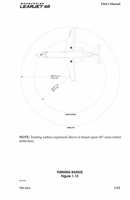
TURNING RADIUSFigure 1-13
NOTE: Turning radius expressed above is based upon 60° nose-wheeldeflection.
39 FT 4 in(12.0 m)
NOSE WHEEL
WING TIP
30 FT 1 in
(9.17 m)
A09-2001
Pilot’s Manual
1-24 PM-126A
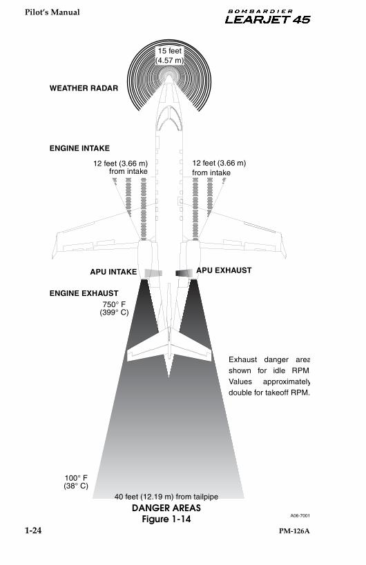
15 feet(4.57 m)
12 feet (3.66 m) from intake
12 feet (3.66 m) from intake
750° F(399° C)
ENGINE EXHAUST
ENGINE INTAKE
WEATHER RADAR
100° F(38° C)
40 feet (12.19 m) from tailpipe
APU INTAKE APU EXHAUST
Exhaust danger areashown for idle RPM.Values approximatelydouble for takeoff RPM.
DANGER AREASFigure 1-14 A06-7001
Pilot’s Manual
PM-126A 1 - 11/ 1 - 12 (Blank)
1.01.0
.2.4.4
.6
.8
.2.4.4
.6
.81.01.0
ON
1
2
3
4
5
6
8
9 10 11 12 13 14 15 16 17
1819
21
22
23
24
25
26
2829303132333435 27
7 20
2-9/2-10 (Blank)1-25/1-26 (Blank)
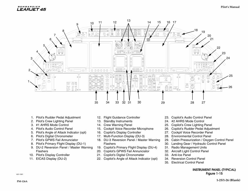
INSTRUMENT PANEL (TYPICAL)Figure 1-15
1. Pilot’s Rudder Pedal Adjustment2. Pilot’s Crew Lighting Panel3. #1 AHRS Mode Control4. Pilot’s Audio Control Panel5. Pilot’s Angle of Attack Indicator (opt)6. Pilot’s Digital Chronometer7. Pilot’s GPWS Fail Annunciator8. Pilot’s Primary Flight Display (DU-1)9. DU-2 Reversion Panel / Master Warning
Flashers10. Pilot’s Display Controller11. EICAS Display (DU-2)
12. Flight Guidance Controller13. Standby Instruments14. Crew Warning Panel15. Cockpit Voice Recorder Microphone16. Copilot’s Display Controller17. Multi-Function Display (DU-3)18. DU-3 Reversion Panel / Master Warning
Flashers19. Copilot’s Primary Flight Display (DU-4)20. Copilot’s GPWS Fail Annunciator21. Copilot’s Digital Chronometer22. Copilot’s Angle of Attack Indicator (opt)
23. Copilot’s Audio Control Panel24. #2 AHRS Mode Control25. Copilot’s Crew Lighting Panel26. Copilot’s Rudder Pedal Adjustment27. Cockpit Voice Recorder Panel28. Environmental Control Panel29. Cabin Pressurization / Oxygen Control Panel30. Landing Gear / Hydraulic Control Panel31. Radio Management Units32. Aircraft Light Control Panel33. Anti-Ice Panel34. Reversion Control Panel35. Electrical Control Panel
Updated 8-29-97 1:45 pmupdated graphic
A31-1001

Pilot’s Manual
PM-126A 1-27
A31-1001a
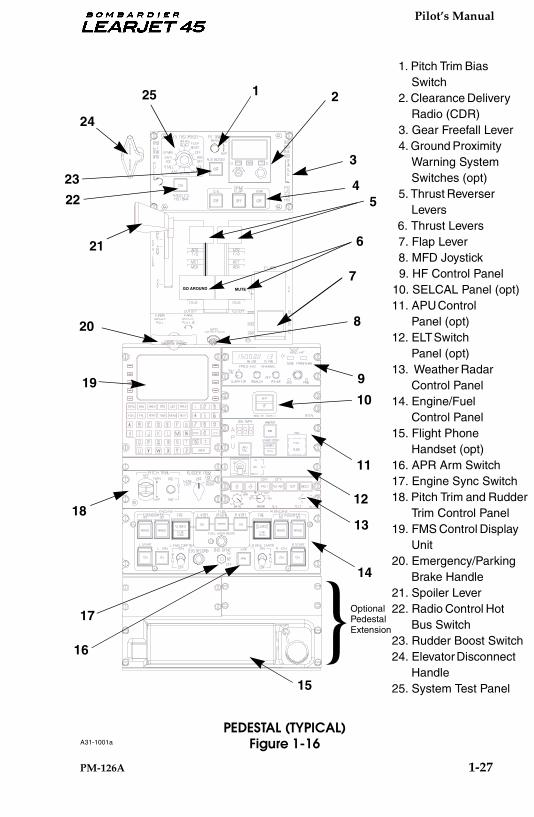
PEDESTAL (TYPICAL)Figure 1-16
ON
1 2
3
45
6
7
8
10
11
12
13
14
19
20
21
22
23
24
25
15
18
GO AROUND MUTE
}
OptionalPedestal Extension
16
17
9
1. Pitch Trim Bias Switch
2. Clearance Delivery Radio (CDR)
3. Gear Freefall Lever 4. Ground Proximity
Warning System Switches (opt)
5. Thrust Reverser Levers
6. Thrust Levers 7. Flap Lever 8. MFD Joystick
9. HF Control Panel10. SELCAL Panel (opt)11. APU Control
Panel (opt)12. ELT Switch
Panel (opt)13. Weather Radar
Control Panel14. Engine/Fuel
Control Panel15. Flight Phone
Handset (opt)16. APR Arm Switch17. Engine Sync Switch18. Pitch Trim and Rudder
Trim Control Panel19. FMS Control Display
Unit20. Emergency/Parking
Brake Handle21. Spoiler Lever22. Radio Control Hot
Bus Switch23. Rudder Boost Switch24. Elevator Disconnect
Handle25. System Test Panel

Pilot’s Manual
1-28 PM-126A
INTENTIONALLY LEFT BLANK

Pilot’s Manual
PM-126A 1 - 11/ 1 - 12 (Blank)
DISPLAY
DAU 1 AHRS PWR
STBY
NOSE STEER
AUX HYD PUMP
L AV BUS
TRIM L ESS BUS
EMER BUS
L FUEL L IGNCOCKPIT L PROBES HT
CKPT INSTRS L FIRE
L HEAT L REVERSER
INSTRUMENTS/INDICATIONS GEAR/HYDRAULICS
LIGHTS ANTI-ICE ENVIRONMENTAL
FLIGHT ELECTRICAL
FUEL ENGINE
L CTRL DU 1 DU 2 MOTOR CMPTR L GEN MAIN ESS
ADC 1 CH A CH B # 1 PRI # 2 SEC GEAR AIL BUS
GYRO PWR CTRL BUS VOLTS
FLOOD L CB AOA PITOT L QTY FLOW CH A CH B
PACK DET EXT FWSOV
NAC WSHLD DEPLOY ANN STOW
L WARN IC/ L ELEV L WHL
INBD SPLR PRI VOLTS/ L HOT
RAD ALT SYSTEM L L FLAP AFCS L RUD
L LEAK L L
L ESS EMER L WING/ RAIN INSTR SYNC L VIB
TAIL BCN/ PAX L OIL
PANEL SG 1 SQUAT DISC MSTR
BRAKES CTRL PITCH START BUS
ALT 1 VIB TEST CLOCK POS SERVOS ADJUST
PRESS DETECT BLEED CMPTR
PWR PWR STAB HT REM FAN SW MON
RECOG STROBE OXY PRESS
L
MAIN
L STBY
L TAXI L STBY
STALL
HYD
PUMP
/LDG PUMP
WARN
PRESS
PWR
CTRL CTRL
LINSTR
MAINTCMPTRDOORSPKRS
CABINLAVL SPOTOVENLAVSINK
GALLEYA/C
MAPDTUMLS
CVRNAV 1DME 1ADF 1FMS 1OSS 1
AFISFLT
PHONECABIN
PA PRI SEC
SELCAL HF 1 ATC 1 COMM 1AUDIO 1/CLR DLY
COMMUNICATIONS
RMU 1 PWR
NAVIGATION
AVIONICS
LIGHTS
CABIN
1 .5 5 10 3 5 1 15 15 7.5 25 2 1 3 5 5 15 35 35
20380553337.5 5555
5
5 5 5
5
5 5
52 3 3
115
333
3 3
3333
33 3 3 3
3107.5
7.5
7.57.57.5
7.5 7.5 7.5 7.5 7.5
7.5 7.5120
3 5 25
1 1 15 20 1 1 1
31212111
2
311
1/2
2
31
15
15
PILOT’S CIRCUIT BREAKER PANEL (TYPICAL)Figure 1-17
1-29/ 1-30 (Blank)
A25-1024

Pilot’s Manual
PM-126A 1 - 11/ 1 - 12 (Blank)
INSTRUMENTS/INDICATIONSFLIGHTELECTRICAL
ENGINE FUEL ANTI-ICE LIGHTS CABIN
ESS MAIN R GEN
RSTALLWARN
R WHLMSTR
RUDFORCE
RSQUAT
IC/SG 2
R HOTBUS
VOLTS/START BUS
PIT TRIMBIAS
SECPITCH RUD
SPLRIND
OUTBDBRAKES
GEN CMPTR DET EXTR RUD
ADJUSTR FLAP
POSFLAPCTRL
#1 SEC
DU 3 DU 4 R CTRLR WARNPANEL
HOURMETER
FDRADC 2CH BCH A#2 PRI
GPWS TCAS
AUDIO 2 COMM 2 ATC 2
PRI SEC PWR
NAV 2 DME 2 ADF 2 FMS 2
GALLEYENTRYOVRHDPEDESTALR CBR
INSTRAOAPITOTICE
DETECTSEC
PRESSR
BLEEDR QTYFLOWCH B
PAXINFO
PAXCTRLS
WINGINSP
CHARTHOLDER
INSTRSR ESSPWR
STBYPITOTSAT
R WING/STAB HTAUTOMANCTRLPWRDETEXTFWSOV
VIDEOAUDIOLOGONAV
R TAXI/LDGCTRLNACWSHLD
FOOTWARM
XFLOWVALVECTRLDEPLOYANNSTOW
CH AR
CMPTR
R OILPRESS
R VIBMON
HF 2 COMM 3
CTRL
OSS 2
R SPOT
TOILETHOT
LIQUIDS
ACOUTLET
/HYD
35 35 15 5 5 2
20 3 80 5 5 5 2
15 10 5 5 3 1
7.5 7.5 7.5 1 1
3 5 1 15 3
35333 1 5 7.5 5 5
132015511
5 2 10 20 15 5 3
1 1 3 7.5 3 5
13227.553
1 7.5 15 15 1 5 1 3 10 5 .5 10
31055
3 1 1 5 3
3 2 1 2 7.5
7.535103
1 20 5 .5
3
GEAR
ENVIR
APU
R AV BUS
R ESS BUS TRIM
FIRE
R IGN R FUEL
R FIRE
R REVERSER
R STBY PUMP TEMP CTRL R PROBES HT
R HEAT
R PROBES HT
AHRS PWR DAU 2
COMMUNICATIONS
RMU 2 PWR RAD HOT BUS
NAVIGATION
COCKPIT LIGHTS
DISPLAY
RCLOCK
RADALT 2 WXR
BRAKEACCUMPRESS
CKPT
AVIONICS
3
2
COPILOT’S CIRCUIT BREAKER PANEL (TYPICAL)Figure 1-18
1-31/ 1-32 (Blank)
A25-1025

Pilot’s Manual
PM-126A II-1
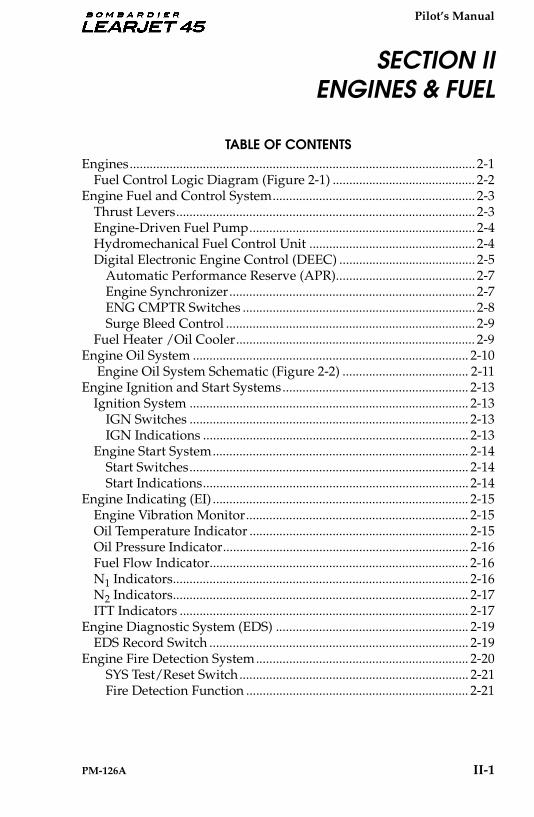
Engines........................................................................................................ 2-1Fuel Control Logic Diagram (Figure 2-1) ........................................... 2-2
Engine Fuel and Control System............................................................. 2-3Thrust Levers.......................................................................................... 2-3Engine-Driven Fuel Pump.................................................................... 2-4Hydromechanical Fuel Control Unit .................................................. 2-4Digital Electronic Engine Control (DEEC) ......................................... 2-5
Automatic Performance Reserve (APR).......................................... 2-7Engine Synchronizer.......................................................................... 2-7ENG CMPTR Switches ...................................................................... 2-8Surge Bleed Control ........................................................................... 2-9
Fuel Heater /Oil Cooler........................................................................ 2-9Engine Oil System ................................................................................... 2-10
Engine Oil System Schematic (Figure 2-2) ...................................... 2-11Engine Ignition and Start Systems........................................................ 2-13
Ignition System .................................................................................... 2-13IGN Switches .................................................................................... 2-13IGN Indications ................................................................................ 2-13
Engine Start System............................................................................. 2-14Start Switches.................................................................................... 2-14Start Indications................................................................................ 2-14
Engine Indicating (EI) ............................................................................. 2-15Engine Vibration Monitor................................................................... 2-15Oil Temperature Indicator .................................................................. 2-15Oil Pressure Indicator.......................................................................... 2-16Fuel Flow Indicator.............................................................................. 2-16N1 Indicators......................................................................................... 2-16N2 Indicators......................................................................................... 2-17ITT Indicators ....................................................................................... 2-17
Engine Diagnostic System (EDS) .......................................................... 2-19EDS Record Switch .............................................................................. 2-19
Engine Fire Detection System................................................................ 2-20SYS Test/Reset Switch..................................................................... 2-21Fire Detection Function ................................................................... 2-21
SECTION IIENGINES & FUEL
TABLE OF CONTENTS
Pilot’s Manual
II-2 PM-126A
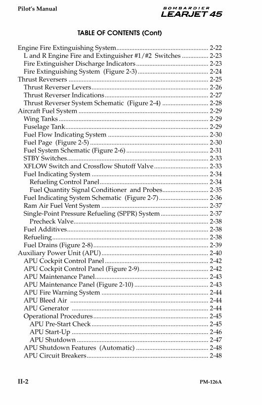
TABLE OF CONTENTS (Cont)
Engine Fire Extinguishing System........................................................ 2-22L and R Engine Fire and Extinguisher #1/#2 Switches ................ 2-23Fire Extinguisher Discharge Indicators ............................................ 2-23Fire Extinguishing System (Figure 2-3) ........................................... 2-24
Thrust Reversers ..................................................................................... 2-25Thrust Reverser Levers....................................................................... 2-26Thrust Reverser Indications............................................................... 2-27Thrust Reverser System Schematic (Figure 2-4) ............................ 2-28
Aircraft Fuel System ............................................................................... 2-29Wing Tanks ........................................................................................... 2-29Fuselage Tank....................................................................................... 2-29Fuel Flow Indicating System ............................................................. 2-30Fuel Page (Figure 2-5) ........................................................................ 2-30Fuel System Schematic (Figure 2-6) .................................................. 2-31STBY Switches...................................................................................... 2-33XFLOW Switch and Crossflow Shutoff Valve ................................. 2-33Fuel Indicating System ....................................................................... 2-34
Refueling Control Panel.................................................................. 2-34Fuel Quantity Signal Conditioner and Probes............................ 2-35
Fuel Indicating System Schematic (Figure 2-7) .............................. 2-36Ram Air Fuel Vent System ................................................................. 2-37Single-Point Pressure Refueling (SPPR) System ............................. 2-37
Precheck Valve.................................................................................. 2-38Fuel Additives...................................................................................... 2-38Refueling............................................................................................... 2-38Fuel Drains (Figure 2-8)...................................................................... 2-39
Auxiliary Power Unit (APU)................................................................. 2-40APU Cockpit Control Panel ............................................................... 2-42APU Cockpit Control Panel (Figure 2-9).......................................... 2-42APU Maintenance Panel..................................................................... 2-43APU Maintenance Panel (Figure 2-10) ............................................. 2-43APU Fire Warning System ................................................................. 2-44APU Bleed Air .................................................................................... 2-44APU Generator ................................................................................... 2-44Operational Procedures ...................................................................... 2-45
APU Pre-Start Check ....................................................................... 2-45APU Start-Up ................................................................................... 2-46APU Shutdown ................................................................................ 2-47
APU Shutdown Features (Automatic) ............................................ 2-48APU Circuit Breakers.......................................................................... 2-48
Change 2

Pilot’s Manual
PM-126A 2-1
ENGINES
The aircraft is powered by two TFE731-20 turbofan engines manufac-tured by Honeywell. These engines are two-spool, geared transonic-stage, front-fan, jet-propulsion engines. Each engine is rated at 3500pounds (15.56 kN) thrust at sea level.
A spinner and an axial-flow fan are located at the forward end of theengine and are gear driven by the low-pressure (N1) rotor. The fan gear-box output-to-input speed ratio is 0.556. The low-pressure rotor con-sists of a four-stage low-pressure axial compressor and a three-stagelow-pressure axial turbine, mounted on a common shaft. The high-pressure (N2) rotor consists of a single-stage centrifugal compressorand a single-stage air-cooled axial turbine, mounted on a commonshaft. The high-pressure rotor drives the accessory gearbox through atransfer gearbox. The rotor shafts are concentric, so that the low-pres-sure rotor shaft passes through the high-pressure rotor shaft.
An annular duct serves to bypass fan air for direct thrust and also di-verts a portion of the fan air to the low-pressure compressor. Air fromthe low-pressure compressor flows through the high-pressure com-pressor and is discharged into the annular combustor. Combustionproducts flow through the high- and low-pressure turbines and are dis-charged axially through the exhaust duct to provide additional thrust.
SECTION IIENGINES & FUEL

Pilot’s Manual
2-2 PM-126A
PAMB —
TLA(Secondary)
AIR DATACOMPUTER
P3
DIGITALELECTRONICENGINECONTROL
CABLERVDT WF/P3
WF
MACH, ALTITUDE, TAMB, PAMB
TLA (Primary)
FUEL
AIR
ELECTRICAL
MECHANICAL
AREA BLEEDAB —
LOW PRESSURE ROTOR (FAN) SPEEDN1 —
HIGH PRESSURE ROTOR (TURBINE) SPEEDN2 —
COMPRESSOR DISCHARGE PRESSUREP3 —
ENGINE INLET TOTAL PRESSUREPT2 —
ENGINE INLET TOTAL TEMPERATURETT2 —
INTERSTAGE TURBINE TEMPERATUREITT —
FUEL FLOWWF —
AMBIENT TEMPERATURETAMB —
THRUST LEVER ANGLETLA —
AMBIENT PRESSURE
TLA (Secondary)
SURGEBLEED
SYSTEM
HYDROMECHANICALFUEL CONTROL UNIT
N2
ITT
N1
AB
TT2
PT2
FUEL CONTROL LOGIC DIAGRAMFigure 2-1

Pilot’s Manual
PM-126A 2-3
ENGINE FUEL AND CONTROL SYSTEM
The engine fuel and control system pressurizes fuel routed to the en-gine from the aircraft fuel system, meters fuel flow, filters the fuel, heatsit as necessary to prevent filter icing, and delivers atomized fuel to thecombustion section of the engine. The system also supplies high-pres-sure motive-flow fuel to the aircraft fuel system for jet pump operation.The major components of the system are the thrust levers, the engine-driven fuel pump, the hydromechanical fuel control unit, the DigitalElectronic Engine Control (DEEC), surge bleed control valve and thefuel heater/oil cooler.
THRUST LEVERS
Two thrust levers, located on the upper portion of the pedestal, are op-erated in a conventional manner with the full forward position beingmaximum power. Stops at the IDLE position prevent inadvertent re-duction of the thrust levers to CUTOFF. The IDLE stops can be releasedby lifting a finger lift on the outboard side of each thrust lever. Detentsare provided for CUTOFF, IDLE, Maximum Cruise (MCR), MaximumContinuous Thrust (MCT), Takeoff (T/O) and Automatic PerformanceReserve (APR).
Primary Thrust Lever Angle (TLA) input to each DEEC is providedthrough Rotary Variable Differential Transformers (RVDTs) locatedwithin the thrust lever quadrant. Secondary TLA input is provided bya control cable connecting each thrust lever to the corresponding en-gine’s hydromechanical fuel control unit.
A flight director go-around button is installed in the left thrust leverhandle. An aural warning horn/voice mute button is installed in theright thrust lever handle. A thrust reverser control lever is mountedpiggyback fashion on each thrust lever. Refer to THRUST REVERSERSin this Section for a functional description of the thrust reverser levers.
The Engine Indicating (EI) display will illuminate a green MCR, MCT,T/O or APR for the corresponding thrust lever detents.
Pilot’s Manual
2-4 PM-126A
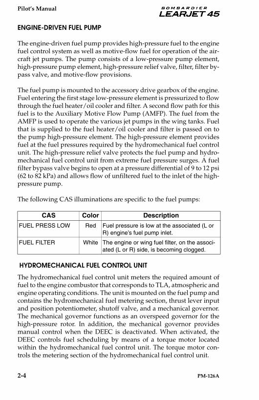
ENGINE-DRIVEN FUEL PUMP
The engine-driven fuel pump provides high-pressure fuel to the enginefuel control system as well as motive-flow fuel for operation of the air-craft jet pumps. The pump consists of a low-pressure pump element,high-pressure pump element, high-pressure relief valve, filter, filter by-pass valve, and motive-flow provisions.
The fuel pump is mounted to the accessory drive gearbox of the engine.Fuel entering the first stage low-pressure element is pressurized to flowthrough the fuel heater/oil cooler and filter. A second flow path for thisfuel is to the Auxiliary Motive Flow Pump (AMFP). The fuel from theAMFP is used to operate the various jet pumps in the wing tanks. Fuelthat is supplied to the fuel heater/oil cooler and filter is passed on tothe pump high-pressure element. The high-pressure element providesfuel at the fuel pressures required by the hydromechanical fuel controlunit. The high-pressure relief valve protects the fuel pump and hydro-mechanical fuel control unit from extreme fuel pressure surges. A fuelfilter bypass valve begins to open at a pressure differential of 9 to 12 psi(62 to 82 kPa) and allows flow of unfiltered fuel to the inlet of the high-pressure pump.
The following CAS illuminations are specific to the fuel pumps:
HYDROMECHANICAL FUEL CONTROL UNIT
The hydromechanical fuel control unit meters the required amount offuel to the engine combustor that corresponds to TLA, atmospheric andengine operating conditions. The unit is mounted on the fuel pump andcontains the hydromechanical fuel metering section, thrust lever inputand position potentiometer, shutoff valve, and a mechanical governor.The mechanical governor functions as an overspeed governor for thehigh-pressure rotor. In addition, the mechanical governor providesmanual control when the DEEC is deactivated. When activated, theDEEC controls fuel scheduling by means of a torque motor locatedwithin the hydromechanical fuel control unit. The torque motor con-trols the metering section of the hydromechanical fuel control unit.
CAS Color Description
FUEL PRESS LOW Red Fuel pressure is low at the associated (L or R) engine’s fuel pump inlet.
FUEL FILTER White The engine or wing fuel filter, on the associ-ated (L or R) side, is becoming clogged.
Pilot’s Manual
PM-126A 2-5
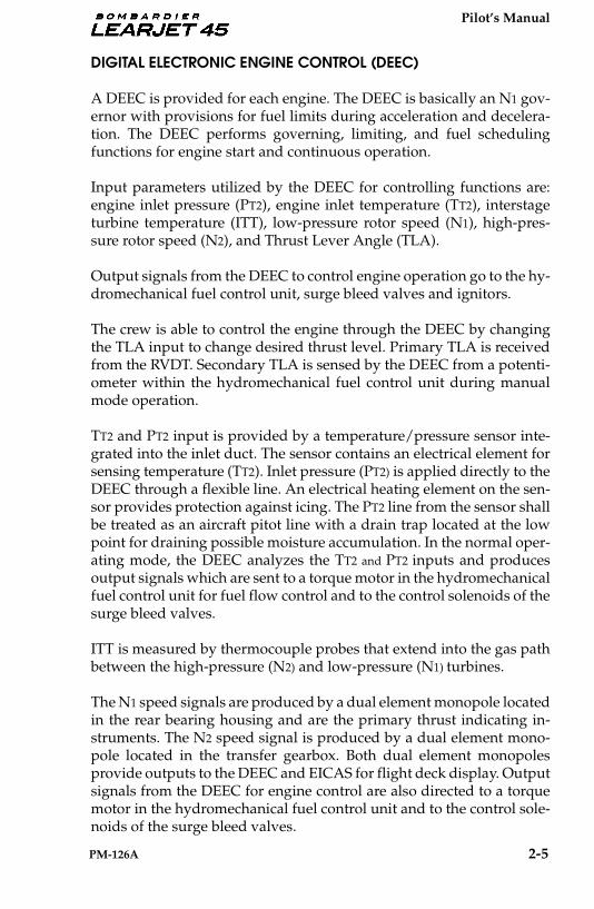
DIGITAL ELECTRONIC ENGINE CONTROL (DEEC)
A DEEC is provided for each engine. The DEEC is basically an N1 gov-ernor with provisions for fuel limits during acceleration and decelera-tion. The DEEC performs governing, limiting, and fuel schedulingfunctions for engine start and continuous operation.
Input parameters utilized by the DEEC for controlling functions are:engine inlet pressure (PT2), engine inlet temperature (TT2), interstageturbine temperature (ITT), low-pressure rotor speed (N1), high-pres-sure rotor speed (N2), and Thrust Lever Angle (TLA).
Output signals from the DEEC to control engine operation go to the hy-dromechanical fuel control unit, surge bleed valves and ignitors.
The crew is able to control the engine through the DEEC by changingthe TLA input to change desired thrust level. Primary TLA is receivedfrom the RVDT. Secondary TLA is sensed by the DEEC from a potenti-ometer within the hydromechanical fuel control unit during manualmode operation.
TT2 and PT2 input is provided by a temperature/pressure sensor inte-grated into the inlet duct. The sensor contains an electrical element forsensing temperature (TT2). Inlet pressure (PT2) is applied directly to theDEEC through a flexible line. An electrical heating element on the sen-sor provides protection against icing. The PT2 line from the sensor shallbe treated as an aircraft pitot line with a drain trap located at the lowpoint for draining possible moisture accumulation. In the normal oper-ating mode, the DEEC analyzes the TT2 and PT2 inputs and producesoutput signals which are sent to a torque motor in the hydromechanicalfuel control unit for fuel flow control and to the control solenoids of thesurge bleed valves.
ITT is measured by thermocouple probes that extend into the gas pathbetween the high-pressure (N2) and low-pressure (N1) turbines.
The N1 speed signals are produced by a dual element monopole locatedin the rear bearing housing and are the primary thrust indicating in-struments. The N2 speed signal is produced by a dual element mono-pole located in the transfer gearbox. Both dual element monopolesprovide outputs to the DEEC and EICAS for flight deck display. Outputsignals from the DEEC for engine control are also directed to a torquemotor in the hydromechanical fuel control unit and to the control sole-noids of the surge bleed valves.
Pilot’s Manual
2-6 PM-126A
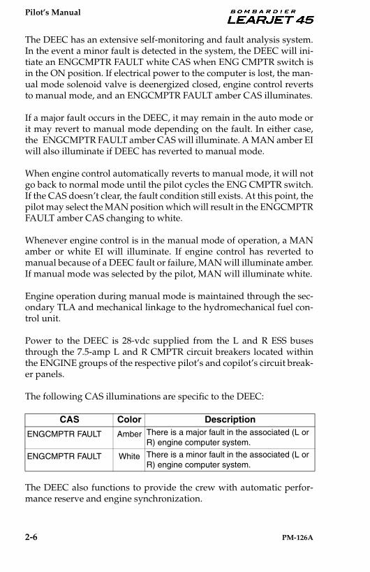
The DEEC has an extensive self-monitoring and fault analysis system.In the event a minor fault is detected in the system, the DEEC will ini-tiate an ENGCMPTR FAULT white CAS when ENG CMPTR switch isin the ON position. If electrical power to the computer is lost, the man-ual mode solenoid valve is deenergized closed, engine control revertsto manual mode, and an ENGCMPTR FAULT amber CAS illuminates.
If a major fault occurs in the DEEC, it may remain in the auto mode orit may revert to manual mode depending on the fault. In either case,the ENGCMPTR FAULT amber CAS will illuminate. A MAN amber EIwill also illuminate if DEEC has reverted to manual mode.
When engine control automatically reverts to manual mode, it will notgo back to normal mode until the pilot cycles the ENG CMPTR switch.If the CAS doesn’t clear, the fault condition still exists. At this point, thepilot may select the MAN position which will result in the ENGCMPTRFAULT amber CAS changing to white.
Whenever engine control is in the manual mode of operation, a MANamber or white EI will illuminate. If engine control has reverted tomanual because of a DEEC fault or failure, MAN will illuminate amber.If manual mode was selected by the pilot, MAN will illuminate white.
Engine operation during manual mode is maintained through the sec-ondary TLA and mechanical linkage to the hydromechanical fuel con-trol unit.
Power to the DEEC is 28-vdc supplied from the L and R ESS busesthrough the 7.5-amp L and R CMPTR circuit breakers located withinthe ENGINE groups of the respective pilot’s and copilot’s circuit break-er panels.
The following CAS illuminations are specific to the DEEC:
The DEEC also functions to provide the crew with automatic perfor-mance reserve and engine synchronization.
CAS Color Description
ENGCMPTR FAULT Amber There is a major fault in the associated (L or R) engine computer system.
ENGCMPTR FAULT White There is a minor fault in the associated (L or R) engine computer system.

Pilot’s Manual
PM-126A 2-7
AUTOMATIC PERFORMANCE RESERVE (APR)
Automatic Performance Reserve (APR) provides a change in thrust onthe operating engine in the event of opposite engine thrust loss duringtakeoff and missed approach conditions. The APR is controlled by theAPR switch located on the aft portion of the pedestal. Depressing theswitch illuminates the white ARM on the switch and the DEEC per-forms a software verification. If the APR circuits are active for both en-gines, an APR white EI will then appear at the top of the EICAS oncethe system is armed by the DEECs. When armed, each DEEC monitorsthe opposite engine in order to automatically increase the maximumavailable thrust if the opposite engine fails. An APR ON green EI willilluminate during automatic APR activity or manual activation. APRmay be manually activated by advancing the thrust lever to the APRdetent. The engine synchronizer will not function during APRoperation.
The following CAS illumination is specific to the APR:
ENGINE SYNCHRONIZER
The engine synchronizer system consists of a three position ENG SYNCN1/N2/OFF switch (located on the aft pedestal), engine synchronizercircuits, and data crosslink communication lines integrated within theDEECs. The synchronizer will function from flight idle to the maxi-mum power rating as long as the engines are operating within the sys-tem authority limits. The authority limits are: ± 5% N1 during midrangeoperation, 0% at takeoff TLA, and -2% to +5% at flight idle. Duringflight, the engine synchronizer, if selected, will maintain the two en-gines’ N1 or N2 in sync with each other. The engine synchronizer mustnot be used during takeoff, landing, or single-engine operations.
If N1 is selected, SYNC green or amber EI will illuminate between theN1 indicators. If N2 is selected, SYNC green or amber EI will illuminatebetween the N2 indicators. The light will be green if the landing gear isup and amber if the gear is down. ENG SYNC should be OFF for take-off and landing; therefore, the amber color is to alert the crew to turnthe synchronization system off if the landing gear is down.
CAS Color DescriptionAPR FAULT White APR fault is detected in the associated (L or
R) DEEC.
Pilot’s Manual
2-8 PM-126A
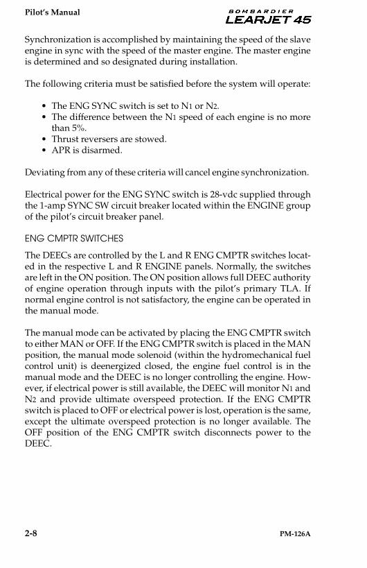
Synchronization is accomplished by maintaining the speed of the slaveengine in sync with the speed of the master engine. The master engineis determined and so designated during installation.
The following criteria must be satisfied before the system will operate:
• The ENG SYNC switch is set to N1 or N2.• The difference between the N1 speed of each engine is no more
than 5%.• Thrust reversers are stowed.• APR is disarmed.
Deviating from any of these criteria will cancel engine synchronization.
Electrical power for the ENG SYNC switch is 28-vdc supplied throughthe 1-amp SYNC SW circuit breaker located within the ENGINE groupof the pilot’s circuit breaker panel.
ENG CMPTR SWITCHES
The DEECs are controlled by the L and R ENG CMPTR switches locat-ed in the respective L and R ENGINE panels. Normally, the switchesare left in the ON position. The ON position allows full DEEC authorityof engine operation through inputs with the pilot’s primary TLA. Ifnormal engine control is not satisfactory, the engine can be operated inthe manual mode.
The manual mode can be activated by placing the ENG CMPTR switchto either MAN or OFF. If the ENG CMPTR switch is placed in the MANposition, the manual mode solenoid (within the hydromechanical fuelcontrol unit) is deenergized closed, the engine fuel control is in themanual mode and the DEEC is no longer controlling the engine. How-ever, if electrical power is still available, the DEEC will monitor N1 andN2 and provide ultimate overspeed protection. If the ENG CMPTRswitch is placed to OFF or electrical power is lost, operation is the same,except the ultimate overspeed protection is no longer available. TheOFF position of the ENG CMPTR switch disconnects power to theDEEC.
Pilot’s Manual
PM-126A 2-9
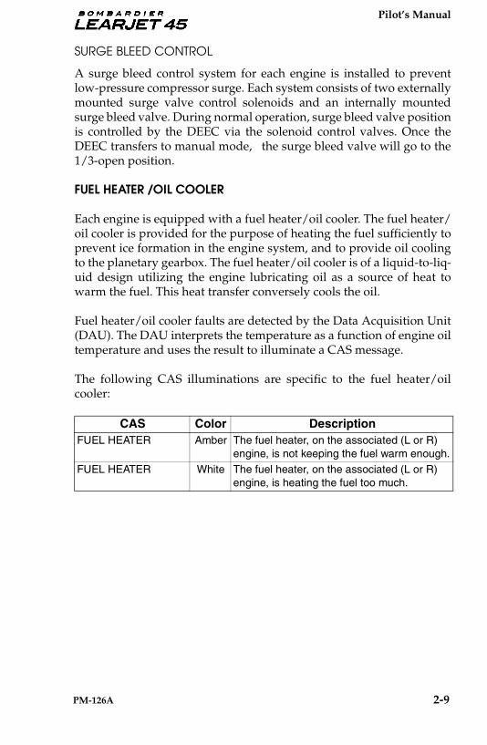
SURGE BLEED CONTROL
A surge bleed control system for each engine is installed to preventlow-pressure compressor surge. Each system consists of two externallymounted surge valve control solenoids and an internally mountedsurge bleed valve. During normal operation, surge bleed valve positionis controlled by the DEEC via the solenoid control valves. Once theDEEC transfers to manual mode, the surge bleed valve will go to the1/3-open position.
FUEL HEATER /OIL COOLER
Each engine is equipped with a fuel heater/oil cooler. The fuel heater/oil cooler is provided for the purpose of heating the fuel sufficiently toprevent ice formation in the engine system, and to provide oil coolingto the planetary gearbox. The fuel heater/oil cooler is of a liquid-to-liq-uid design utilizing the engine lubricating oil as a source of heat towarm the fuel. This heat transfer conversely cools the oil.
Fuel heater/oil cooler faults are detected by the Data Acquisition Unit(DAU). The DAU interprets the temperature as a function of engine oiltemperature and uses the result to illuminate a CAS message.
The following CAS illuminations are specific to the fuel heater/oilcooler:
CAS Color DescriptionFUEL HEATER Amber The fuel heater, on the associated (L or R)
engine, is not keeping the fuel warm enough.FUEL HEATER White The fuel heater, on the associated (L or R)
engine, is heating the fuel too much.
Pilot’s Manual
2-10 PM-126A
ENGINE OIL SYSTEM
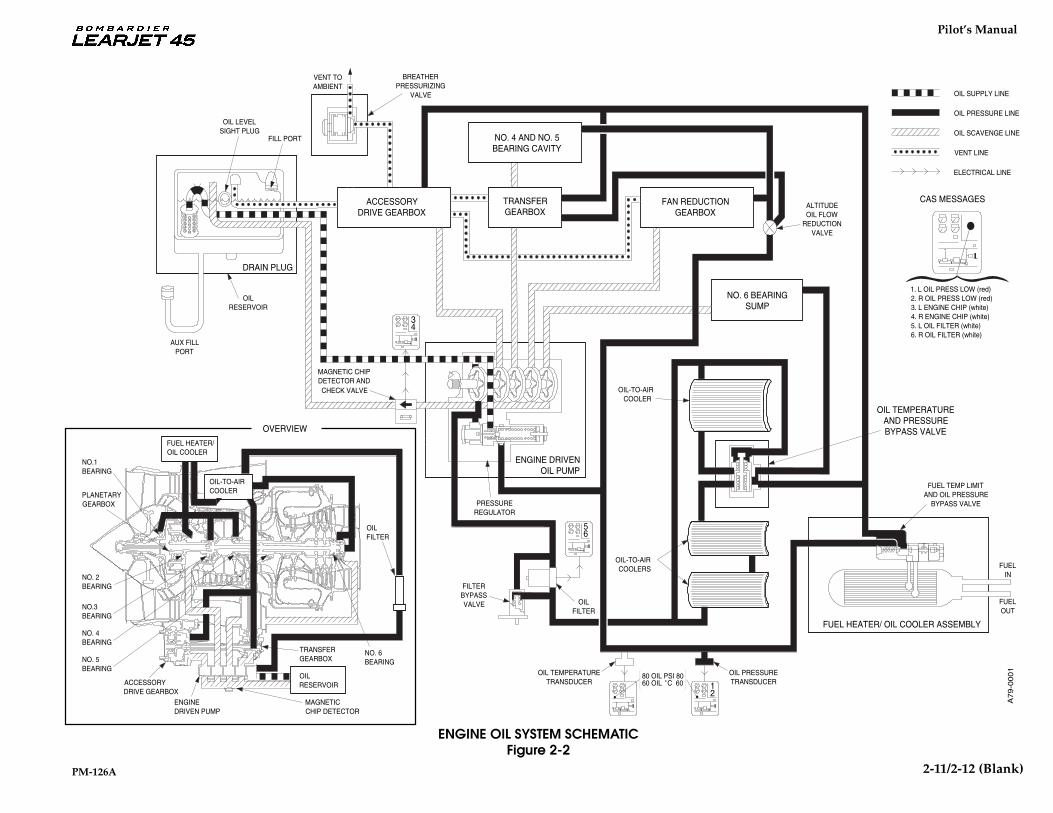
Oil for engine lubrication is drawn from the engine oil tank by the oilpump. The oil is output from the pump through a filter, a pressure reg-ulator valve, an oil-to-air cooler, and a fuel heater/oil cooler. The oil-to-air cooler is a three-segment, finned cooler that forms the inner surfaceof the fan duct. From the oil-to-air cooler, the oil flow is divided so thatpart of the oil is directed to the accessory drive and transfer gearboxes,and the engine shaft bearings. The remaining oil is diverted to a fuelheater/oil cooler and then to the planetary gearbox.
The oil filter assembly incorporates a bypass valve and an electricalswitch to indicate when the oil filter is clogged or clogging. In the eventof an impending bypass, an L or R OIL FILTER white CAS will illumi-nate. The bypass valve will open when the pressure differential acrossthe filter reaches 35 psi (241 kPa) allowing oil to bypass the filter. Undercold oil conditions, such as engine start, the bypass indication is inhib-ited when the oil temperature is less than approximately 100° F (38° C);however, the bypass valve will still open. This function prevents nui-sance indications during engine start due to high oil viscosity at coldtemperatures.
The following CAS illumination is specific to the engine oil system:
CAS Color DescriptionOIL FILTER White The associated (L or R) engine oil filter is
becoming plugged.
Pilot’s Manual
PM-126A 2--11
VENT TOAMBIENT
BREATHERPRESSURIZING
VALVE
OILRESERVOIR
OIL LEVELSIGHT PLUG
FILL PORT
AUX FILLPORT
FILTERBYPASSVALVE OIL
FILTER
PRESSUREREGULATOR
OIL TEMPERATURETRANSDUCER
OIL PRESSURETRANSDUCER
80 OIL PSI 80
OIL-TO-AIRCOOLERS
OIL-TO-AIRCOOLER
FUEL TEMP LIMITAND OIL PRESSURE
BYPASS VALVE
ALTITUDEOIL FLOW
REDUCTIONVALVE
ENGINE DRIVENOIL PUMP
FUEL HEATER/ OIL COOLER ASSEMBLY
DRAIN PLUG
OIL TEMPERATUREAND PRESSUREBYPASS VALVE
ACCESSORYDRIVE GEARBOX
NO. 4 AND NO. 5BEARING CAVITY
TRANSFERGEARBOX
FAN REDUCTIONGEARBOX
NO. 6 BEARINGSUMP
NO.1BEARING
PLANETARYGEARBOX
NO. 2BEARING
NO.3BEARING
NO. 4BEARING
NO. 5BEARING
ACCESSORYDRIVE GEARBOX
ENGINEDRIVEN PUMP
MAGNETICCHIP DETECTOR
OILRESERVOIR
NO. 6BEARING
TRANSFERGEARBOX
FUELIN
FUELOUT
CAS MESSAGES
OIL SUPPLY LINE
OIL PRESSURE LINE
OIL SCAVENGE LINE
VENT LINE
ELECTRICAL LINE
1. L OIL PRESS LOW (red)2. R OIL PRESS LOW (red)3. L ENGINE CHIP (white)4. R ENGINE CHIP (white)5. L OIL FILTER (white)6. R OIL FILTER (white)
34
56
2160 OIL C 60o
OILFILTER
CHECK VALVE
MAGNETIC CHIPDETECTOR AND
OVERVIEW
OIL-TO-AIRCOOLER
FUEL HEATER/OIL COOLER
A7
9-0
00
1
ENGINE OIL SYSTEM SCHEMATICFigure 2-2
2-11/2-12 (Blank)
Pilot’s Manual
PM-126A 2-13
ENGINE IGNITION AND START SYSTEMS
IGNITION SYSTEM
The engine ignition system is an integral sub-system of the engine.Each engine consists of an ignition unit, two ignitor plugs, two shieldedhigh-voltage output cables and associated aircraft wiring. During nor-mal engine operation the system is controlled by the DEEC and is capa-ble of continuous operation. The DEEC powers the ignition system forthree modes of operation. The first is for normal engine start. Duringnormal engine start the DEEC commands ignition at >6.0% N2 andturns ignition off when N1 = 0.7 of idle N1. The second mode is for un-commanded deceleration, and the third mode prevents engine flame-out during rapid deceleration.
The ignition unit is a solid-state, high-voltage, capacitor-discharge unitmounted on the fan bypass duct of each engine. The unit provides aspark rate of 2 sparks per second at an output of 18,000 to 24,000 voltsthrough the ignitor plugs. The ignitor plugs are located on the combus-tor plenum at the 4 and 8 o’clock positions. These iridium plugs arelinked to the ignition unit by separate high-voltage cables and sparkwhen pulsed by the ignition unit.
The ignition system is powered by 28-vdc from the L and R ESS busesthrough the CH A and CH B circuit breakers located within the EN-GINE groups (respective L and R IGN) of the pilot’s and copilot’s cir-cuit breaker panels.
IGN SWITCHES
The L and R IGN switches, located in the respective ENGINE panel ofthe pedestal, are used to obtain continuous engine ignition. The switchcontrolling the left engine ignition system is labeled L IGN. The switchcontrolling the right engine ignition system is labeled R IGN. When anIGN switch is placed in the ON position, 28-vdc is applied to the engineignition unit.
IGN INDICATIONS
The EI will display a green, white, and amber IGN. The green EI repre-sents normal ignition activity. A white EI is generated if one ignitorplug is not firing. The amber EI alerts the pilot of dual ignitor plugfailure.
Pilot’s Manual
2-14 PM-126A
ENGINE START SYSTEM
A combined starter/generator is mounted on the front of the accessorygearbox. For normal starts, the DEEC provides for automatic startingwhich allows the thrust lever to be moved into the IDLE position beforeactivating the starter. When the respective L or R START switch is mo-mentarily depressed, the DEEC begins the start sequence by activatingthe corresponding standby fuel pump and energizing the starter relayclosed. The starter relay connects electrical power to the starter fromthe respective L or R GEN bus. Power to the GEN buses is suppliedfrom the aircraft batteries, an external power source, or an AuxiliaryPower Unit (APU) (if installed).
An external power source or APU is recommended for starts when am-bient temperature is 32° F (0° C) or below. Ensure an external powersource supply is regulated to 28-vdc, has adequate capacity for enginestarting and is limited to 1500 amps maximum. Allow the operatinggenerator amperage to decrease below 300 amps prior to a generatorcross-start. Refer to Cold Weather Operation, AFM, for additional in-formation when operating in extremely cold weather.
START SWITCHES
The L and R START switches, located in the respective ENGINE panelof the pedestal, are guarded momentary action switches that illuminateON when depressed indicating the starter relay is energized.
START INDICATIONS
During engine starts, a vertical START green or amber EI will appear.The green EI represents normal starter activity. The amber EI representsan engine starter engaged with N2 greater than 51%.
Pilot’s Manual
PM-126A 2-15
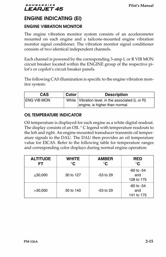
ENGINE INDICATING (EI)ENGINE VIBRATION MONITOR
The engine vibration monitor system consists of an accelerometermounted on each engine and a tailcone-mounted engine vibrationmonitor signal conditioner. The vibration monitor signal conditionerconsists of two identical independent channels.
Each channel is powered by the corresponding 3-amp L or R VIB MONcircuit breaker located within the ENGINE group of the respective pi-lot’s or copilot’s circuit breaker panels.
The following CAS illumination is specific to the engine vibration mon-itor system:
OIL TEMPERATURE INDICATOR
Oil temperature is displayed for each engine as a white digital readout.The display consists of an OIL ° C legend with temperature readouts tothe left and right. An engine-mounted transducer transmits oil temper-ature signals to the DAU. The DAU then provides an oil temperaturevalue for EICAS. Refer to the following table for temperature rangesand corresponding color displays during normal engine operation:
CAS Color DescriptionENG VIB MON White Vibration level, in the associated (L or R)
engine, is higher than normal.
ALTITUDEFT
WHITE °C
AMBER°C
RED°C
<30,000 30 to 127 -53 to 29-60 to -54
and128 to 175
>30,000 30 to 140 -53 to 29-60 to -54
and141 to 175

Pilot’s Manual
2-16 PM-126A
OIL PRESSURE INDICATOR
Oil pressure is displayed for each engine as a digital readout on EICAS.The display consists of an OIL PSI legend with pressure readouts to theleft and right.
Refer to the following table for pressure ranges and corresponding col-or display during normal engine operation:
FUEL FLOW INDICATOR
Fuel flow is displayed for each engine as a white digital readout onEICAS. The display consists of a FF PPH legend with flow rates to theleft and right. The fuel flow rates are presented in Pounds-Per-Hour(PPH). A fuel flow transmitter located in the main fuel line of each en-gine supplies fuel flow signals to the DAU via a fuel flow converter. TheDAU then provides a fuel flow rate value for EICAS presentation.
N1 INDICATORS
The fan speed (N1) analog EI for each engine consists of a needle, arc,and N1 bug with integral digital readouts for N1 and N1 setting. The N1
sensor is mounted in the engine’s rear bearing support housing andsenses low-pressure fan speed. The sensor provides signals to theDEEC and DAU. Refer to the following table for N1 speeds and corre-sponding color display.
(% N2) WHITE PSIG
AMBERPSIG
REDPSIG
<80% and up to3 minutes after
engine start65 to 80 50 to 64
0 to 49and
126 to 150
>80% or more than 3 minutes
after engine start65 to 80 50 to 64
0 to 49and
101 to 150
WHITE % N1
AMBER% N1
RED% N1
0 to 100.0 N/A 100.1 to 115*
*Above 115% the digits are invalid.

Pilot’s Manual
PM-126A 2-17
N2 INDICATORS
N2 is displayed for each engine as a digital readout. The display con-sists of an N2 legend with digital readouts to the left and right. Refer tothe following table for N2 speeds and corresponding color display forvarious conditions.
ITT INDICATORS
Interstage Turbine Temperature (ITT) is displayed for each engine as aneedle and arc with an integral digital readout for ITT. The arc is scaledto start at 100° C. Interstage turbine temperature for each engine issensed by Chromel-Alumel parallel wired thermocouples positionedbetween the high- and low-pressure turbine sections. The signal fromthe averaging circuit of the thermocouples is carried to the DEEC andDAU for EI display. Refer to the following table for ITT and corre-sponding color display for various conditions.
Aircraft 45-002 & Subsequent not modified by SB 45-72-1:
% N2WHITE % N2
AMBER% N2
RED% N2
Except APR Mode 0 to 100 100.1 to 102.5 102.6 to 115*
APR Mode 0 to 101 101.1 to 102.5 102.6 to 115*
OPERATING MODE
WHITE °C
AMBER°C
RED°C
Start 0 to 941 N/A 942 to 1014
Takeoff (<5 minutes)
0 to 941 N/A 942 to 1014
Takeoff or APR(>5 minutes)
0 to 916 917 to 941 942 to 1014
APR(<5 minutes)
0 to 963 N/A 964 to 1014
Up To MCR 0 to 900 N/A 901 to 1014
MCT (no anti-ice) 0 to 916 N/A 917 to 1014
MCT (any anti-ice) 0 to 941 N/A 942 to 1014
*Above 115% the digits are invalid.
Pilot’s Manual
2-18 PM-126A
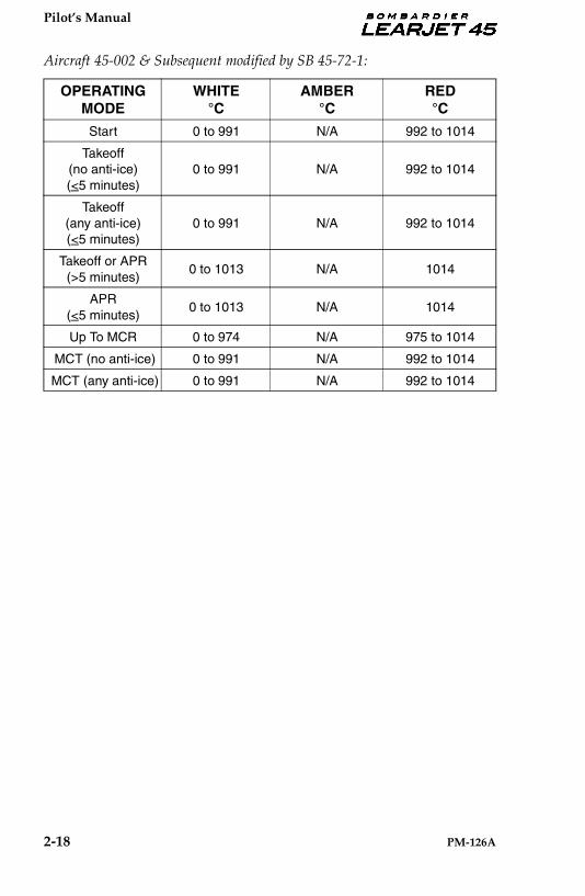
Aircraft 45-002 & Subsequent modified by SB 45-72-1:
OPERATING MODE
WHITE °C
AMBER°C
RED°C
Start 0 to 991 N/A 992 to 1014
Takeoff (no anti-ice)(<5 minutes)
0 to 991 N/A 992 to 1014
Takeoff(any anti-ice)(<5 minutes)
0 to 991 N/A 992 to 1014
Takeoff or APR(>5 minutes)
0 to 1013 N/A 1014
APR(<5 minutes)
0 to 1013 N/A 1014
Up To MCR 0 to 974 N/A 975 to 1014
MCT (no anti-ice) 0 to 991 N/A 992 to 1014
MCT (any anti-ice) 0 to 991 N/A 992 to 1014
Pilot’s Manual
PM-126A 2-19
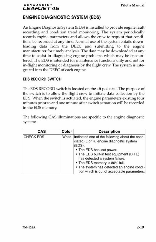
ENGINE DIAGNOSTIC SYSTEM (EDS)
An Engine Diagnostic System (EDS) is installed to provide engine faultrecording and condition trend monitoring. The system periodicallyrecords engine parameters and allows the crew to request that condi-tions be recorded at any time. Normal use of the system entails down-loading data from the DEEC and submitting to the enginemanufacturer for timely analysis. The data may be downloaded at anytime to assist in diagnosing engine problems which may be encoun-tered. The EDS is intended for maintenance functions only and not forin-flight monitoring or diagnosis by the flight crew. The system is inte-grated into the DEEC of each engine.
EDS RECORD SWITCH
The EDS RECORD switch is located on the aft pedestal. The purpose ofthe switch is to allow the flight crew to initiate data collection by theEDS. When the switch is actuated, the engine parameters existing fourminutes prior to and one minute after switch actuation will be recordedin the EDS memory.
The following CAS illuminations are specific to the engine diagnosticsystem:
CAS Color DescriptionCHECK EDS White Indicates one of the following about the asso-
ciated (L or R) engine diagnostic system (EDS):• The EDS has lost power.• The EDS built-in test equipment (BITE)
has detected a system failure.• The EDS memory is 80% full.• The system has detected an engine condi-
tion which is out of acceptable parameters.

Pilot’s Manual
2-20 PM-126A
ENGINE FIRE DETECTION SYSTEM
Three heat-sensing elements connected in series are located in each en-gine nacelle to detect an engine fire. One element is located around theaccessory gearbox; one is located around the engine tailcone; and an-other around the engine firewall. The fire detection system is controlledby two fire detect control boxes located in the tailcone. In the event ofan engine fire, the applicable control box will sense a resistance changein the sensing elements and flash the master WARN lights in theglareshield and applicable FIRE switch located within the L or RENGINE panel of the aft pedestal.
The FIRE red EI will flash within the arc of the ITT dial. Warning is giv-en if the firewall or accessory gearbox area exceeds approximately410° F (210° C), or the engine tailcone area exceeds approximately890° F (477° C).
Whenever an engine fire is detected a “LEFT” or “RIGHT ENGINEFIRE” voice message will sound to both pilots’ headphones and flightdeck speakers. This voice message is continuous, but can be silenced bydepressing the mute switch located on the right thrust lever or the mas-ter WARN light.
Electrical power for the system is 28-vdc supplied through the 1-amp Land R FIRE DET circuit breakers located within the ENGINE group ofthe pilot’s and copilot’s circuit breaker panels respectively. Fire detectsystems are powered from the respective L and R ESS buses.

Pilot’s Manual
PM-126A 2-21
SYS TEST/RESET SWITCH
FIRE DETECTION FUNCTION
The rotary-type SYS TEST/RESET switch on the forward pedestal isused to test the fire detection system. Rotating the switch to FIRE DETand depressing the switch (PRESS TEST) button will connect a resis-tance into both fire detect system circuits. This resistance, simulating anengine fire, will test system indications as follows:
- Master WARN tone and light will activate followed bya “LEFT ENGINE FIRE . . . RIGHT ENGINE FIRE”voice.
- Both red FIRE and all white EXTINGUISHER #1 and #2ARMED switches (ENGINE panel) will illuminate.Illumination of the FIRE switch indicates continuity ofthe fire detect systems and illumination of the EXTIN-GUISHER #1 and #2 ARMED switches indicate conti-nuity of the fire extinguisher squibs.
- Red FIRE messages in ITTs will flash.
Both red FIRE messages on RMU ENGINE PGE 1will flash next to the N1 display.
- L and R BLEED AIR LEAK red CAS and CWP. Thisindicates continuity of the bleed air overheat sensorsystem.
- WING/STAB LEAK red CAS and CWP. This indicatescontinuity of the anti-ice bleed air overheat sensorsystem.
- APU FIRE Switch (if installed) and a red CAS will illu-minate with the APU MASTER Switch ON. The redCAS only will illuminate if the APU MASTER Switch isOff.
Depressing and holding the SYS TEST/RESETSwitch in the FIRE DET position for 15 seconds willresult in the APU fire horn sounding. Holding theswitch for 30 seconds will result in an APU FAIL in-dication and APU shutdown.
NOTE
NOTE

Pilot’s Manual
2-22 PM-126A
ENGINE FIRE EXTINGUISHING SYSTEM
The engine fire extinguishing system components include: two spheri-cal extinguishing agent containers, a red FIRE PUSH light/switch foreach engine, two white EXTINGUISHER #1 and #2 ARMED light/switches for each engine, one hydraulic shutoff valve for each engine,one fuel shutoff valve for each engine, a thermal discharge indicator, amanual discharge indicator, and associated wiring and plumbing. Thesystem also utilizes the pneumatic system bleed air shutoff valves. Thesystem is plumbed to provide the contents of either or both extinguish-ing agent containers to either engine nacelle. Shuttle valves are in-stalled to prevent extinguishing agent flow between containers. Theextinguishing agent, Halon 1301 (Bromotrifluromethane [CF3Br]), isstored under pressure (600 psi) in the extinguisher containers and apressure gauge on each container is visible from inside the tailcone. Ha-lon 1301 is non-toxic at normal temperatures and is non-corrosive. AsHalon 1301 is non-corrosive, no special cleaning of the engine or nacellearea is required in the event the system has been used. The system op-erates on 28-vdc supplied through the 5-amp L and R FIRE EXT circuitbreakers located within the respective ENGINE group of the pilot’s andcopilot’s circuit breaker panels. Fire extinguishing systems are pow-ered from the EMER BATT hot bus.
Pilot’s Manual
PM-126A 2-23
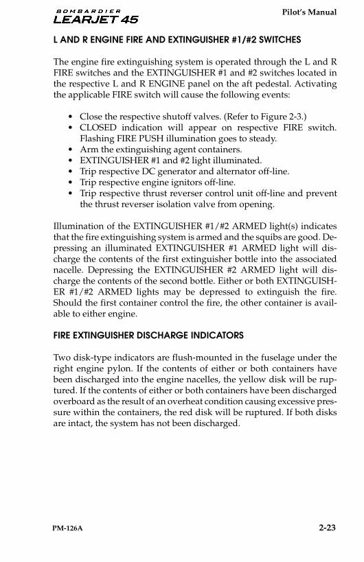
L AND R ENGINE FIRE AND EXTINGUISHER #1/#2 SWITCHES
The engine fire extinguishing system is operated through the L and RFIRE switches and the EXTINGUISHER #1 and #2 switches located inthe respective L and R ENGINE panel on the aft pedestal. Activatingthe applicable FIRE switch will cause the following events:
• Close the respective shutoff valves. (Refer to Figure 2-3.)• CLOSED indication will appear on respective FIRE switch.
Flashing FIRE PUSH illumination goes to steady.• Arm the extinguishing agent containers.• EXTINGUISHER #1 and #2 light illuminated.• Trip respective DC generator and alternator off-line.• Trip respective engine ignitors off-line.• Trip respective thrust reverser control unit off-line and prevent
the thrust reverser isolation valve from opening.
Illumination of the EXTINGUISHER #1/#2 ARMED light(s) indicatesthat the fire extinguishing system is armed and the squibs are good. De-pressing an illuminated EXTINGUISHER #1 ARMED light will dis-charge the contents of the first extinguisher bottle into the associatednacelle. Depressing the EXTINGUISHER #2 ARMED light will dis-charge the contents of the second bottle. Either or both EXTINGUISH-ER #1/#2 ARMED lights may be depressed to extinguish the fire.Should the first container control the fire, the other container is avail-able to either engine.
FIRE EXTINGUISHER DISCHARGE INDICATORS
Two disk-type indicators are flush-mounted in the fuselage under theright engine pylon. If the contents of either or both containers havebeen discharged into the engine nacelles, the yellow disk will be rup-tured. If the contents of either or both containers have been dischargedoverboard as the result of an overheat condition causing excessive pres-sure within the containers, the red disk will be ruptured. If both disksare intact, the system has not been discharged.
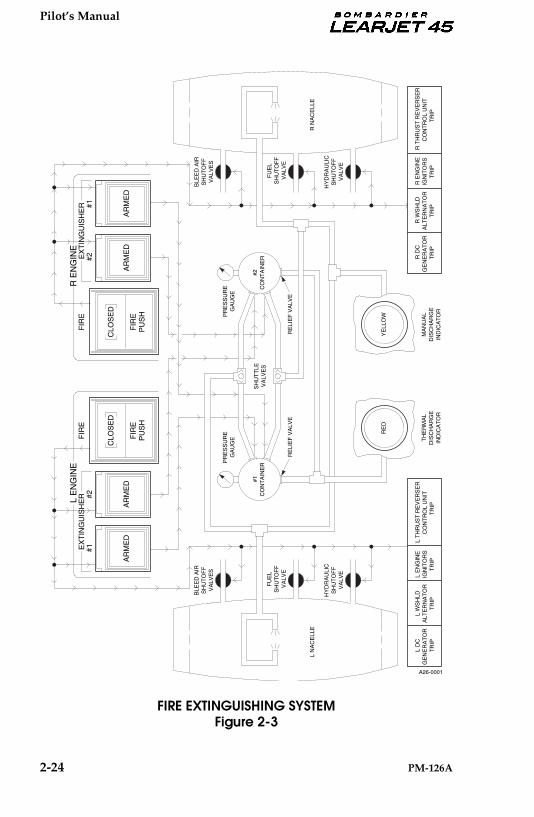
Pilot’s Manual
2-24 PM-126A
FIRE EXTINGUISHING SYSTEMFigure 2-3
AR
ME
DA
RM
ED
CLO
SE
D
FIR
EP
US
H
#1#2
EX
TIN
GU
ISH
ER
FIR
EL
EN
GIN
E
CLO
SE
D
FIR
EP
US
H
FIR
E
AR
ME
DA
RM
ED
#1#2E
XT
ING
UIS
HE
RR
EN
GIN
E
L N
AC
ELL
E
BLE
ED
AIR
SH
UT
OF
FV
ALV
ES
FU
EL
SH
UT
OF
FV
ALV
E
#1C
ON
TA
INE
R
PR
ES
SU
RE
GA
UG
E
RE
D
SH
UT
TLE
VA
LVE
S
R N
AC
ELL
E
R D
C G
EN
ER
AT
OR
T
RIP
R W
SH
LDA
LTE
RN
AT
OR
TR
IP
R E
NG
INE
IGN
ITO
RS
TR
IP
R T
HR
US
T R
EV
ER
SE
RC
ON
TR
OL
UN
ITT
RIP
YE
LLO
W
#2C
ON
TA
INE
R
RE
LIE
F V
ALV
ER
ELI
EF
VA
LVE
PR
ES
SU
RE
GA
UG
E TH
ER
MA
LD
ISC
HA
RG
EIN
DIC
AT
OR
MA
NU
AL
DIS
CH
AR
GE
IND
ICA
TO
R
HY
DR
AU
LIC
SH
UT
OF
FV
ALV
E
BLE
ED
AIR
SH
UT
OF
FV
ALV
ES
FU
EL
SH
UT
OF
FV
ALV
E
HY
DR
AU
LIC
SH
UT
OF
FV
ALV
E
A26-0001
L D
C G
EN
ER
AT
OR
T
RIP
L W
SH
LDA
LTE
RN
AT
OR
TR
IP
L E
NG
INE
IGN
ITO
RS
TR
IP
L T
HR
US
T R
EV
ER
SE
RC
ON
TR
OL
UN
ITT
RIP

Pilot’s Manual
PM-126A 2-25
THRUST REVERSERS Each engine is equipped with an independent, electrically controlled,hydraulically actuated, clamshell-type thrust reverser. The thrust re-verser system consists of a thrust reverser control unit, an engine na-celle afterbody on each engine, a piggy-back thrust reverser lever oneach main thrust lever, associated hydraulic plumbing, and associatedelectrical wiring.
The thrust reverser control unit integrates all deploy, stow, and indica-tion functions of the thrust reverser system. Input signals indicating thestatus of each of these functions are analyzed by the thrust reversercontrol unit. Different combinations of these signals will generate theapplicable output command from the thrust reverser control unit.
Each nacelle afterbody consists of an upper and lower blocker door, aninboard and outboard primary deploy/stow actuator, unlatch actuator,unlatch switch, unlock switch, full deploy switch, and a throttle retardmechanism. Hydraulic power for thrust reverser operation is suppliedby the aircraft hydraulic system. A selector valve for each thrust revers-er is installed in the tailcone. The selector valves control hydraulic flowto the associated system actuators in response to electrical inputs fromthe associated thrust reverser lever and position switches via the thrustreverser control unit.
The thrust reverser levers and the system circuit breakers are the onlycontrols used by the crew to operate the system. Electrical power forthrust reverser control and indication circuits is 28-vdc supplied by theL and R ESS buses through the L and R REVERSER circuit breakers. TheL REVERSER circuit breakers located in the ENGINE group of the pi-lot’s circuit breaker panel include the 5-amp DEPLOY, the 3-amp ANN,and the 3-amp STOW. The R REVERSER circuit breakers located withinthe ENGINE group of the copilot’s circuit breaker panel also include a5-amp DEPLOY, a 3-amp ANN, and a 3-amp STOW.
In order to arm the thrust reversers, both main gear weight-on-wheelsswitches must be in the ground mode (aircraft weight on the main gear)and the thrust levers must be in the IDLE position. When fully armed(reverser system relays and switches are properly sequenced), the asso-ciated isolation valve is open and the system is ready for deploy/stowcommands by operation of the thrust reverser levers.
The clam-shell type blocker doors are held in the stowed position bylatch hooks. The latch hooks are hinged to the unlatch actuator, and arerotated away from the blocker doors for thrust reverser deployment.When the deploy cycle is initiated, hydraulic pressure is applied to thestow side of the primary actuators which move the doors into an

Pilot’s Manual
2-26 PM-126A
overstowed condition. Overstowing the thrust reversers allows the un-latch actuators to rotate the latch hooks. As the latch hooks begin to ro-tate, the unlock switch signals the thrust reverser control unit of theunlocked condition. As the latch hooks clear the blocker door recepta-cles, an unlatch switch signals the thrust reverser control unit that theblocker doors are unlatched. After the latch hooks are unlatched, hy-draulic pressure is applied to the deploy side of the primary actuatorswhich push the doors open.
Stow is initiated automatically whenever an unlock condition is detect-ed and the thrust reverser lever is forward of the thrust reverser deploydetent. This occurs during the normal stow cycle and also to correct anabnormal condition in flight. During autostow, hydraulic pressure isapplied to the stow side of the primary actuators and the blocker doorsmove towards the overstow position. As the doors reach overstow, thespring-loaded latches close. When the latches close, the unlock switch-es are deactivated. The selector valve then releases stow pressure on theprimary stow/deploy actuator. Exhaust gas pressure and springs re-turn the doors to the normal stowed position.
An automatic throttle retard mechanism is installed on each thrust re-verser to ensure that thrust reverser stow and deploy does not occurwith an engine thrust setting above idle. The throttle retard mechanismconsists of an actuator, crank, and lever. Whenever hydraulic stowpressure is applied to the thrust reverser actuators, the throttle retardmechanism will position thrust lever to the IDLE position. When hy-draulic stow pressure is removed, the mechanism will return to a neu-tral position and release retard pressure to the thrust lever.
THRUST REVERSER LEVERS
A thrust reverser control lever for each thrust reverser is mountedpiggy-back fashion on each main thrust lever. The thrust reverser leversare inoperable and cannot be moved unless the associated main thrustlevers are at the IDLE stop. Similarly, the main thrust levers cannot bemoved from the IDLE position until the associated thrust reverser leveris in the stow (full down) position. When fully armed, a thrust reversermay be independently deployed by lifting the corresponding thrust re-verser lever to the first (idle/deploy) stop. A throttle release will acti-vate and the thrust reverser lever may be pulled beyond the idle/deploy stop to increase reverse thrust. If both thrust reversers are de-ployed, a detent limits thrust reverser lever travel to approximatelyMCR.
The thrust reverser is stowed by first returning the thrust reverser leverto the idle/deploy stop and then moving the lever to the stow (fulldown) position at engine idle speed.
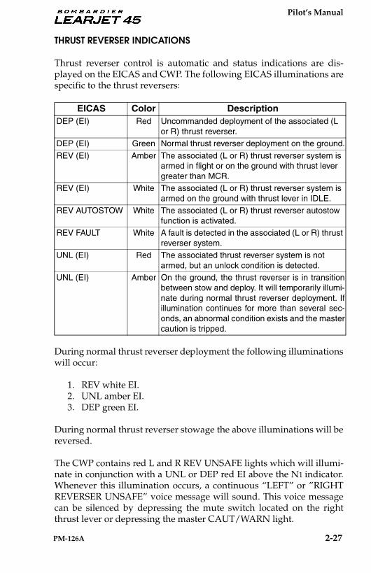
Pilot’s Manual
PM-126A 2-27
THRUST REVERSER INDICATIONS
Thrust reverser control is automatic and status indications are dis-played on the EICAS and CWP. The following EICAS illuminations arespecific to the thrust reversers:
During normal thrust reverser deployment the following illuminationswill occur:
1. REV white EI.2. UNL amber EI.3. DEP green EI.
During normal thrust reverser stowage the above illuminations will bereversed.
The CWP contains red L and R REV UNSAFE lights which will illumi-nate in conjunction with a UNL or DEP red EI above the N1 indicator.Whenever this illumination occurs, a continuous “LEFT” or ”RIGHTREVERSER UNSAFE” voice message will sound. This voice messagecan be silenced by depressing the mute switch located on the rightthrust lever or depressing the master CAUT/WARN light.
EICAS Color DescriptionDEP (EI) Red Uncommanded deployment of the associated (L
or R) thrust reverser.DEP (EI) Green Normal thrust reverser deployment on the ground.
REV (EI) Amber The associated (L or R) thrust reverser system is armed in flight or on the ground with thrust lever greater than MCR.
REV (EI) White The associated (L or R) thrust reverser system is armed on the ground with thrust lever in IDLE.
REV AUTOSTOW White The associated (L or R) thrust reverser autostow function is activated.
REV FAULT White A fault is detected in the associated (L or R) thrust reverser system.
UNL (EI) Red The associated thrust reverser system is not armed, but an unlock condition is detected.
UNL (EI) Amber On the ground, the thrust reverser is in transitionbetween stow and deploy. It will temporarily illumi-nate during normal thrust reverser deployment. Ifillumination continues for more than several sec-onds, an abnormal condition exists and the mastercaution is tripped.
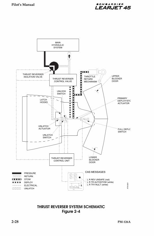
Pilot’s Manual
2-28 PM-126A
THRUST REVERSER SYSTEM SCHEMATICFigure 2-4
L R TR AUTOSTOW (white)L R REV UNSAFE (red)
L R TR FAULT (white)
CAS MESSAGES
LOWERBLOCKERDOOR
UPPERBLOCKERDOOR
PRIMARYDEPLOY/STOACTUATOR
STOW
DEPLOY
ELECTRICAL
UNLATCH
RETURN
PRESSURE
MAINHYDRAULIC
SYSTEM
THRUST REVERSERISOLATION VALVE
THRUST REVERSERCONTROL UNIT
FULL DEPLOSWITCH
UNLOCKSWITCH
UNLATCHACTUATOR
LATCHHOOKS
THROTTLERETARDMECHANISM
UNLATCHSWITCH
THRUST REVERSERCONTROL VALVE
A78
-000
1
Pilot’s Manual
PM-126A 2-29
AIRCRAFT FUEL SYSTEM
The aircraft fuel system consists of two wing tanks, a fuselage tank, afuel flow indicating system, a fuel quantity indicating system, a fueltransfer system, a fuel vent/expansion system and a single-point pres-sure refueling system.
WING TANKS
The wing is divided into two separate fuel-tight compartments whichserve as fuel tanks. Each tank extends from the wing root to a point justshort of the winglets, thus providing a separate fuel supply for each en-gine. A crossflow shutoff valve is installed to permit fuel transfer be-tween wing tanks. Wing tank over-pressurization is prevented byvent/expansion lines between the wing tanks and fuselage tank. Thisallows access to the main fuel vent/expansion system of the fuselagetank. Flapper-type check valves, located in the various wing ribs, al-lowing free fuel flow inboard but restricted outboard fuel flow. A mainjet pump is mounted in each wing tank near the center bulkhead tosupply fuel under pressure to the respective engine fuel system. Astandby pump also located at this location can be utilized as a back-upfor the main jet pump, or be used to transfer fuel from wing tank towing tank or defuel the aircraft. Three scavenge jet pumps, locatedthroughout each wing tank, are used to transfer fuel to the inboard col-lector bay containing the main fuel jet pump. A fourth scavenge jetpump, located in the forward end of the collector tank, is used to trans-fer fuel to the inlet of the main fuel pumps. A fifth scavenge jet pump,located in the outlet of the fuselage to wing transfer line, is used to as-sist gravity in the transfer of fuel from fuselage to wing during normalaircraft operation. The wings are filled from the fuselage tank throughthe refueling manifold or the gravity filler port.
FUSELAGE TANK
The fuselage tank consists of a single bladder-type cell located in the aftfuselage. The tank is equipped with a pressure refueling adapter, agravity filler port, a fuel probe, a refueling manifold/nozzle, and a fuelvent/expansion system with an auxiliary vacuum/pressure reliefvalve. The tank allows the entire fuel system to be serviced through apressure refueling adapter located on the right side of the aircraft belowthe engine pylon, or a gravity filler port located on the right side of theaircraft above the engine pylon. The gravity transfer system is boostedby motive flow through the refueling manifold/nozzle during refuel-ing operations. Fuel will flow to both wing tanks through two transferlines.
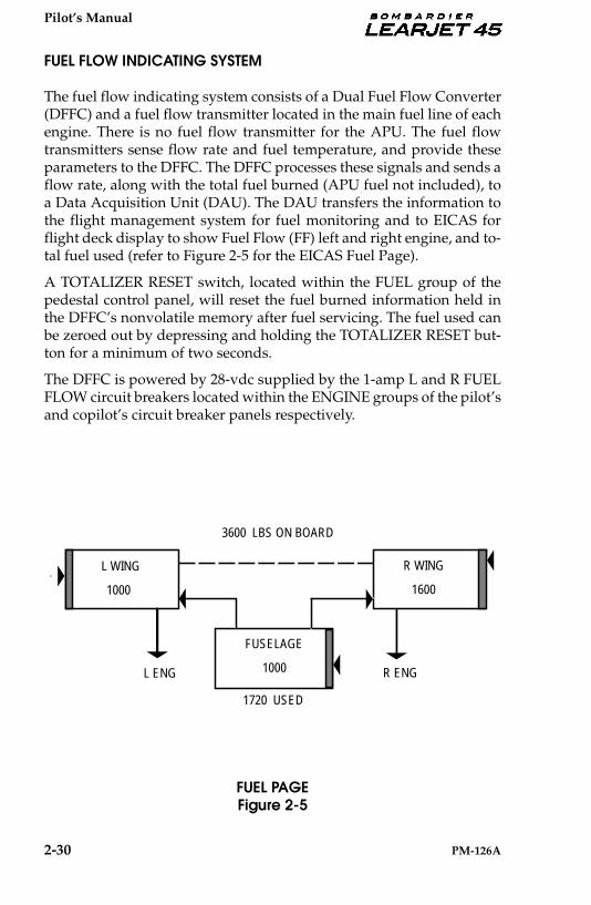
Pilot’s Manual
2-30 PM-126A
FUEL FLOW INDICATING SYSTEM
The fuel flow indicating system consists of a Dual Fuel Flow Converter(DFFC) and a fuel flow transmitter located in the main fuel line of eachengine. There is no fuel flow transmitter for the APU. The fuel flowtransmitters sense flow rate and fuel temperature, and provide theseparameters to the DFFC. The DFFC processes these signals and sends aflow rate, along with the total fuel burned (APU fuel not included), toa Data Acquisition Unit (DAU). The DAU transfers the information tothe flight management system for fuel monitoring and to EICAS forflight deck display to show Fuel Flow (FF) left and right engine, and to-tal fuel used (refer to Figure 2-5 for the EICAS Fuel Page).
A TOTALIZER RESET switch, located within the FUEL group of thepedestal control panel, will reset the fuel burned information held inthe DFFC’s nonvolatile memory after fuel servicing. The fuel used canbe zeroed out by depressing and holding the TOTALIZER RESET but-ton for a minimum of two seconds.
The DFFC is powered by 28-vdc supplied by the 1-amp L and R FUELFLOW circuit breakers located within the ENGINE groups of the pilot’sand copilot’s circuit breaker panels respectively.
FUEL PAGEFigure 2-5
FUSELAGE
1000
L WING
1000
R WING
1600
1720 USED
3600 LBS ON BOARD
L ENG R ENG
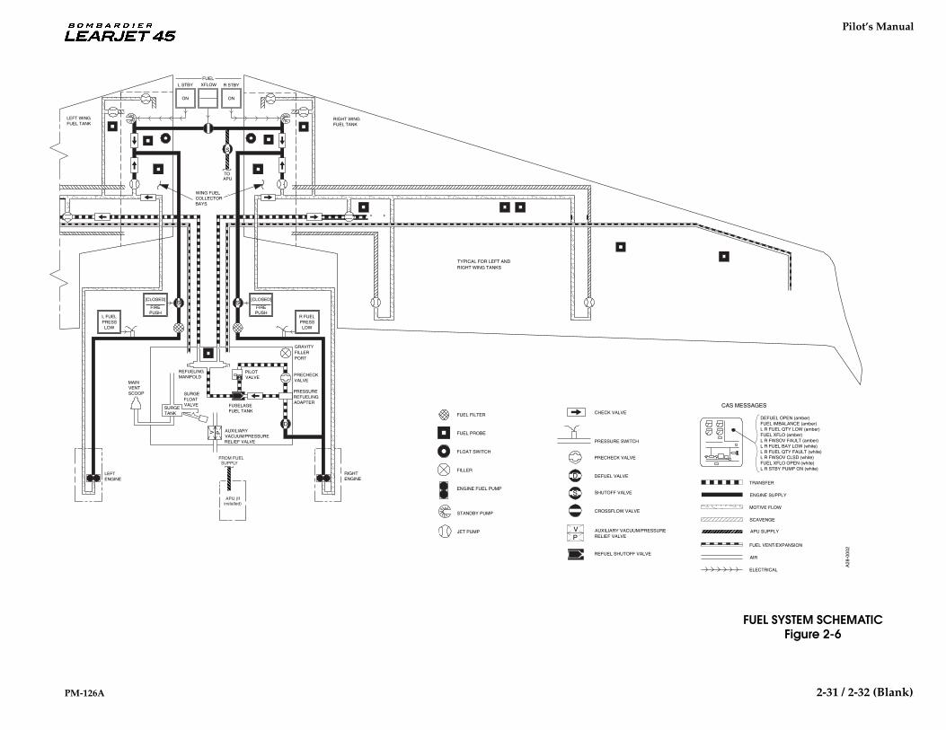
Pilot’s Manual
PM-126A 2--31
D
S
V P
S
V
S
D
FUEL PROBE
FUEL FILTER
FLOAT SWITCH
FILLER
ENGINE FUEL PUMP
STANDBY PUMP
JET PUMP
REFUEL SHUTOFF VALVE
CHECK VALVE
PRESSURE SWITCH
PRECHECK VALVE
DEFUEL VALVE
SHUTOFF VALVE
CROSSFLOW VALVE
PAUXILIARY VACUUM/PRESSURERELIEF VALVE
TRANSFER
MOTIVE FLOW
SCAVENGE
FUEL VENT/EXPANSION
AIR
DEFUEL OPEN (amber)
L R FUEL BAY LOW (white)
FUEL IMBALANCE (amber)L R FUEL QTY LOW (amber)FUEL XFLO (amber)
L R FWSOV CLSD (white)
L R FWSOV FAULT (amber)
L R FUEL QTY FAULT (white)
FUEL XFLO OPEN (white)L R STBY PUMP ON (white)
CAS MESSAGES
PRESSUREREFUELINGADAPTER
PRECHECKVALVE
REFUELINGMANIFOLD
FUSELAGEFUEL TANK
PILOTVALVE
SURGETANK
SURGEFLOATVALVE
MAINVENTSCOOP
AUXILIARYVACUUM/PRESSURERELIEF VALVE
[CLOSED]
FIREPUSH
[CLOSED]
FIREPUSH
R FUELPRESSLOW
L FUELPRESSLOW
LEFT WINGFUEL TANK
WING FUELCOLLECTORBAYS
RIGHT WINGFUEL TANK
GRAVITYFILLERPORT
RIGHTENGINE
LEFTENGINE
TYPICAL FOR LEFT ANDRIGHT WING TANKS
ELECTRICAL
FUEL
ON ON
L STBY XFLOW R STBY
A28
-000
2
FROM FUEL SUPPLY
APU (If installed)
APU SUPPLY
ENGINE SUPPLY
S
TO APU
2-31 / 2-32 (Blank)
FUEL SYSTEM SCHEMATICFigure 2-6

Pilot’s Manual
PM-126A 2-33
STBY SWITCHES
The L and R STBY switches, within the FUEL group of the aft pedestal,manually control the operation of the electric standby pumps. Thesemomentary switches normally remain off. In the event of a main jetpump failure or during fuel crossflow, the L and R STBY switches mustbe manually selected to ON by the flight crew. The standby pumps areautomatically energized during engine start (begins when the L or RSTART switch is depressed, and stops at 50% N2). The right standbypump is automatically energized during APU start and run. When thestandby pumps are operating, the L and/or R STBY switches will illu-minate ON.
The standby pumps operate on 28-vdc supplied through the 15-amp Land R STBY PUMP PWR circuit breakers within the FUEL groups of thepilot’s and copilot’s circuit breaker panels respectively. The automaticand manual pump controls are powered by 28-vdc through the 3-ampL and R STBY PUMP CTRL circuit breakers located within the FUELgroups of the pilot’s and copilot’s circuit breaker panels respectively.
The following CAS illuminations are specific to the standby fuelpumps:
XFLOW SWITCH AND CROSSFLOW SHUTOFF VALVE
The XFLOW switch, within the FUEL group of the aft pedestal, controlsthe crossflow shutoff valve. The valve is normally in the closed posi-tion. Depressing the XFLOW switch illuminates a white bar and poweris applied to open the motorized crossflow shutoff valve allowing fuelto flow between the wing tanks.
To balance wing fuel, the XFLOW switch should be set to open (whitebar illuminated) and the heavy side L or R STBY switch set to ON. Thestandby pump will continue to operate until the L or R STBY switch isdeselected. The crossflow shutoff valve allows all usable fuel aboardthe aircraft to be available to either engine. The switch should not be se-lected except when correcting an out-of-balance condition.
The crossflow shutoff valve operates on 28-vdc supplied from the rearhot bus through the 5-amp XFLOW VALVE CTRL circuit breaker locat-ed within the FUEL group of the copilot’s circuit breaker panel. Loss ofpower to the crossflow shutoff valve causes the valve to remain in itslast commanded position.
CAS Color DescriptionFUEL PRESS LOW Red Fuel pressure is low at the associated (L or
R) engine’s fuel pump inlet.STBY PUMP ON White The associated (L or R) standby fuel pump is
receiving electrical power.

Pilot’s Manual
2-34 PM-126A
The following CAS illuminations are specific to the XFLOW switch andcrossflow shutoff valve:
FUEL INDICATING SYSTEM
The fuel indicating system consists of a refueling control panel, a fuelquantity signal conditioner, 16 wing tank fuel quantity probes (8 eachwing), and a fuselage tank fuel quantity probe. The system providesfuel quantity accuracy which indicates zero at zero fuel and is correctedfor pitch and roll through the AHRS system.
Power for the fuel indicating system is 28-vdc supplied through the 1-amp L and R QTY circuit breakers located within the FUEL groups ofthe pilot and copilot circuit breaker panels respectively.
REFUELING CONTROL PANEL
The refueling control panel is located on the exterior of the aircraft be-low the right engine pylon. The panel is energized by the FUEL PNLON/OFF switch. This switch also activates a floodlight when placed inthe ON/FLD LT position. This floodlight is installed below the right en-gine pylon and is energized from the EMER BATT hot bus to allow re-fueling without accessing the aircraft. The DEFUEL/READY/OFFswitch opens the defuel shutoff valve and the crossflow shutoff valvewhen selected to READY for defueling operations. An amber LED in-dicator above the READY will illuminate when both valves are open. Agreen LED indicator below the OFF will illuminate when both valvesare closed. A four-digit LED labeled TOTAL FUEL QTY will indicatetotal usable fuel in LB or KG depending on aircraft configuration.
CAS Color DescriptionFUEL PRESS LOW Red Fuel pressure is low at the associated (L or
R) engine’s fuel pump inlet.FUEL XFLO Amber The fuel crossflow valve is not fully opened or
closed as commanded.FUEL XFLO OPEN White The fuel crossflow valve is open.
STBY PUMP ON White The associated (L or R) standby fuel pump is receiving electrical power.
Pilot’s Manual
PM-126A 2-35
FUEL QUANTITY SIGNAL CONDITIONER AND PROBES
The fuel quantity signal conditioner is based on two independentlypowered left and right wing channels. Each channel receives DC inputsfrom their respective wing probes. Both channels independently mon-itor the fuselage probe and receive aircraft pitch information from theAHRS #1 unit. This data significantly increases the accuracy of the fuelindicating system during climb and descent. Each channel monitors thedata output of the other for calculating total fuel quantity for transmit-tal to the DAUs. Although each channel outputs the same fuel quantityinformation, the DAUs will only read specific information. DAU #1reads left quantity and total quantity. DAU #2 reads right quantity andfuselage quantity. A weight-on-wheels input allows for separate calcu-lation software to operate “on the ground” or “in the air”, making thesystem more accurate in both environments.
Aircraft 45-002 thru 45-258, and 45-260:
A wing fuel imbalance greater than 500 lb (227 kg) with flaps up orgreater than 200 lb (91 kg) with flaps greater than 3° will generate theFUEL IMBALANCE amber CAS.
Aircraft 45-259, 45-261 thru 45-2000:
A wing fuel imbalance greater than or equal to 200 lb (91 kg) will gen-erate the FUEL IMBALANCE amber CAS.
The fuel quantity signal conditioner software determines low fuel con-ditions from the filtered fuel quantity. The L or R FUEL QTY LOW am-ber CAS is generated when fuel quantity is less than 350 pounds. The following CAS illuminations are specific to the fuel quantity indi-cating system:
CAS Color DescriptionFUEL IMBALANCE Amber A fuel imbalance exists between the left and
right wing tanks.FUEL QTY LOW Amber The fuel quantity in the associated (L or R)
wing tank is approaching a minimum desired level for flight.
FUEL QTY FAULT White - When message preceded by L or R:A fault is detected in the associated channel of the fuel quantity indicating system.
- When message not preceded by L or R:The fuselage fuel probe is invalid or attitude input from the AHRS to the fuel quantity indicating system is invalid.
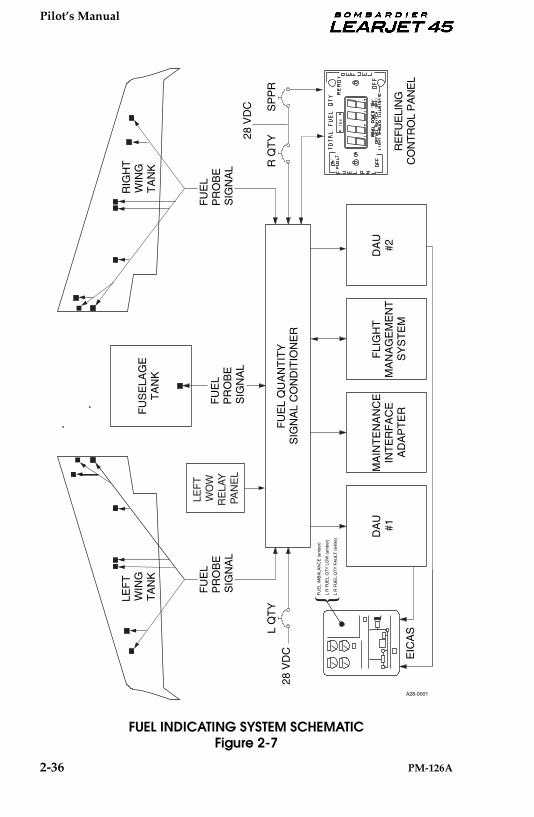
Pilot’s Manual
2-36 PM-126A
FUEL INDICATING SYSTEM SCHEMATICFigure 2-7
FU
EL
QU
AN
TIT
YS
IGN
AL
CO
ND
ITIO
NE
R
LEF
TW
ING
TA
NK
MA
INT
EN
AN
CE
INT
ER
FA
CE
AD
AP
TE
R
FLI
GH
TM
AN
AG
EM
EN
TS
YS
TE
M
DA
U#1
DA
U#2
EIC
AS
RIG
HT
WIN
GT
AN
K
28 V
DC
R Q
TY
28 V
DC
L Q
TY
FU
EL
PR
OB
ES
IGN
AL
FU
EL
PR
OB
ES
IGN
AL
FU
EL
PR
OB
ES
IGN
AL
FU
SE
LAG
ET
AN
K
A28-0001
SP
PR
RE
FU
ELI
NG
CO
NT
RO
L P
AN
EL
/
lbs
LEF
T
WO
WR
ELA
Y
PAN
EL
FU
EL
IMB
ALA
NC
E (
ambe
r)
L R
FU
EL
QT
Y L
OW
(am
ber)
L R
FU
EL
QT
Y F
AU
LT (
whi
te)
�
Pilot’s Manual
PM-126A 2-37
RAM AIR FUEL VENT SYSTEM
The fuel vent system provides ram air pressure to all interconnectedcomponents of the fuel system to ensure positive pressure during allflight conditions. A flush-mounted ram air scoop (NACA vent scoop)located on the left side of the fuselage (forward of the engine) admitspressure to the fuselage tank main vent system. The main vent systempressurizes the wing tanks through the fuel vent/expansion lines. Thefuselage fuel vent/expansion lines are each connected to a separatesump that has a moisture drain valve. Overpressurization due to ther-mal expansion in the wing tanks is relieved through the left and rightexpansion lines to the fuselage tank. Overpressurization of the fuselagetank is relieved overboard through the NACA vent scoop. The vacu-um/pressure relief valve is a backup for the NACA vent scoop.
SINGLE-POINT PRESSURE REFUELING (SPPR) SYSTEM
The Single-Point Pressure Refueling (SPPR) system allows the entirefuel system to be serviced through a SPPR adapter located on the rightside of the aircraft below the engine pylon. The SPPR incorporates aprecheck system which allows the operator to check the operation ofthe system shutoff valves before commencing refuel operations. Themajor system components are the refueling adapter, refueling panel,refuel shutoff valve, pilot valve, precheck valve, and associated plumb-ing and wiring.
Electrical power to operate the system indicator lights, solenoid valvesand fuel quantity signal conditioner is 28-vdc supplied from the EMERBATT hot bus through the PWR ON switch on the refuel control panel.
The refuel shutoff valve is controlled by the pilot valve located at thehigh point in the fuselage tank. When refueling pressure is applied tothe system through the pressure refueling adapter, pressurized fuel isapplied to the refuel shutoff valve. This pressure is applied to bothsides of the valve poppet. If the pilot valve is open, some of the pressureacting to hold the valve closed will be vented through the pilot valveand the pressure acting to unseat the poppet will drive the valve openagainst the spring tension. When the tank fills, the pilot valve will close,fuel pressure on both sides of the refuel shutoff valve poppet willequalize, and spring tension will drive the valve closed. If the refuelshutoff valve malfunctions, fuel will vent out of the NACA vent scoopto prevent overpressurization of the fuselage tank.
Pilot’s Manual
2-38 PM-126A
PRECHECK VALVE
The precheck valve is used to check operation of the system shutoffvalve before full refueling procedures are commenced. When the pre-check valve is set to PRECHECK OPEN and refuel pressure is appliedto the refuel adapter, fuel will be admitted to the precheck line. Theshutoff valve will open and fuel will flow into the fuselage tank. Thefuel in the precheck line will empty into a float basin at the pilot valve.When the basin fills, the pilot valve float will close the pilot valve,which causes the shutoff valve to close, terminating fuel flow. Fuel flowshould stop within 20 seconds.
FUEL ADDITIVES
Refer to Airplane Flight Manual Addendum I Fuel Servicing for recom-mended concentrations and the proper blending methods of approvedfuel additives.
REFUELING
The aircraft is refueled through a gravity filler cap located on the rightside of the fuselage above the engine pylon or through the single-pointpressure refueling (SPPR) adapter located on the right side of the fuse-lage below the engine pylon. A refueling panel access door is locatednext to the SPPR adapter access door. Refer to Airplane Flight ManualAddendum I Fuel Servicing for a list of approved fuels and refuelingprocedures.
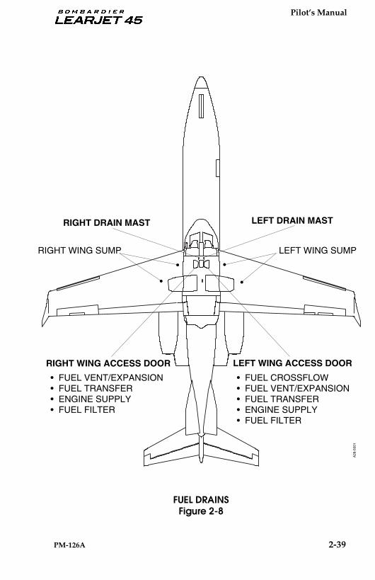
Pilot’s Manual
PM-126A 2-39
FUEL DRAINSFigure 2-8
RIGHT DRAIN MAST
RIGHT WING ACCESS DOOR
LEFT DRAIN MAST
LEFT WING SUMPRIGHT WING SUMP
• FUEL VENT/EXPANSION• FUEL TRANSFER• ENGINE SUPPLY• FUEL FILTER
LEFT WING ACCESS DOOR
• FUEL CROSSFLOW• FUEL VENT/EXPANSION• FUEL TRANSFER• ENGINE SUPPLY• FUEL FILTER
•
•
•
•
A28
-500
1
Pilot’s Manual
2-40 PM-126A
AUXILIARY POWER UNIT (APU)
The Auxiliary Power Unit (APU), located in a special enclosure abovethe baggage compartment and tailcone equipment bay, is a self-con-tained, single-stage gas turbine unit that can be operated continuouslyup to an ambient temperature of 125° F (52° C). The APU providespneumatic and electric power for ground operations of the aircraft En-vironmental Control System and aircraft electrical systems, indepen-dent of the aircraft main engines. It is restricted to ground operationsonly. The starting, acceleration and operation of the engine is controlledby an integral system of automatic and coordinated pneumatic andelectromechanical controls.
The APU engine is comprised of three major sections: the accessory sec-tion, compressor section and turbine section. Engine power for the aux-iliary power unit is developed through compression of ambient air bya single entry, radial, outward-flow, centrifugal compressor. The com-pressed air, when mixed with fuel and ignited, drives a radial inward-flow turbine rotor.
The APU control panel (located on the center pedestal) contains all ofthe primary controls to operate the APU. There is also a MaintenanceControl Panel in the tailcone equipment bay (primarily for mainte-nance use). There is an EMER SHUTDOWN switch on this panel.
The engine is controlled and serviced by four systems: the engine fuelsystem, lubrication system, electrical system and indicating system.Fuel for the APU flows from the right wing fuel tank through the rightstandby pump and shutoff valve prior to reaching the APU. The APUuses approximately 150 pounds of fuel per hour. The APU should notbe started and run in excess of 1 hour with less than 200 pounds in theright wing tank. Running out of fuel in the right wing tank will intro-duce air in the APU fuel lines which will cavitate the APU and preventit from restarting immediately. The APU gearbox serves as an oil sumpfor the APU self-contained lubrication system. The APU ElectronicControl Unit (ECU) is a fully automatic system that directs delivery ofthe correct amount of fuel regardless of ambient conditions and load re-quirements, as well as properly sequencing control of fuel and ignitionduring starting. The ECU is also used for trend monitoring (in lieu of astart counter or hour meter, etc.), which is accessed through the RS 232maintenance port on the Maintenance Control Panel.
A warning horn is installed in the nose avionics bay. The audible alertcan be heard out of the nose gear wheel well to alert personnel outsideof the aircraft of an APU fire.
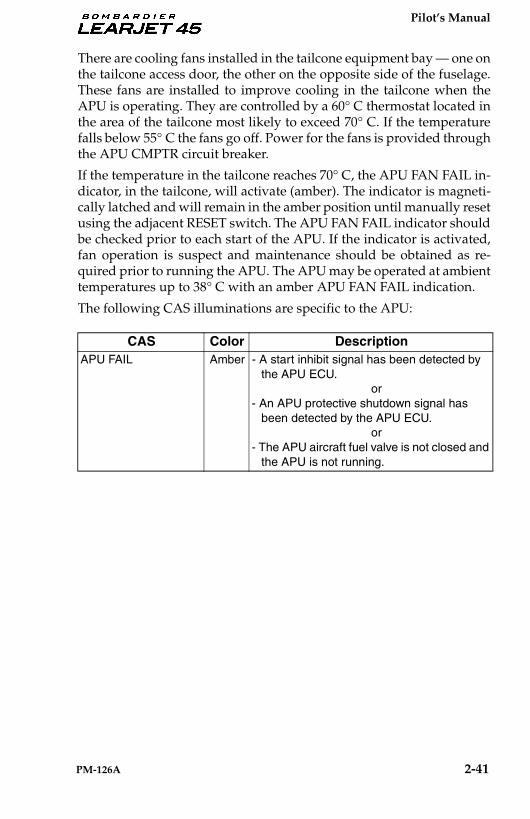
Pilot’s Manual
PM-126A 2-41
There are cooling fans installed in the tailcone equipment bay — one onthe tailcone access door, the other on the opposite side of the fuselage.These fans are installed to improve cooling in the tailcone when theAPU is operating. They are controlled by a 60° C thermostat located inthe area of the tailcone most likely to exceed 70° C. If the temperaturefalls below 55° C the fans go off. Power for the fans is provided throughthe APU CMPTR circuit breaker.
If the temperature in the tailcone reaches 70° C, the APU FAN FAIL in-dicator, in the tailcone, will activate (amber). The indicator is magneti-cally latched and will remain in the amber position until manually resetusing the adjacent RESET switch. The APU FAN FAIL indicator shouldbe checked prior to each start of the APU. If the indicator is activated,fan operation is suspect and maintenance should be obtained as re-quired prior to running the APU. The APU may be operated at ambienttemperatures up to 38° C with an amber APU FAN FAIL indication.
The following CAS illuminations are specific to the APU:
CAS Color DescriptionAPU FAIL Amber - A start inhibit signal has been detected by
the APU ECU.or
- An APU protective shutdown signal has been detected by the APU ECU.
or- The APU aircraft fuel valve is not closed and
the APU is not running.

Pilot’s Manual
2-42 PM-126A
APU COCKPIT CONTROL PANEL
The APU cockpit control panel, located on the center pedestal, housesthe necessary controls for operation and monitoring. APU fire detec-tion/extinguishing controls are also located on the APU cockpit controlpanel.
APU FAIL — The APU FAIL (amber) indicator shows a failure in theAPU control or indication system. The indicator will also show if theaircraft fuel valve is not closed and the APU is not running.
APU MASTER — The APU MASTER switch/indicator is an alternate-action push-button switch. When selected ON, the ECU is powered anda bit test is started. If the test fails the APU FAIL indicator will come on.
APU FIRE — This switch/indicator is used to show an APU system fireand activate the APU fire extinguishing system. Should there be a firein the APU, as detected by the fire loop, the FIRE switch/indicator willindicate FIRE PUSH (red), the aircraft Master WARN lights willilluminate, and the APU fire warning horn will sound. The firedetection/extinguishing system will automatically shut down the APUand activate the fire extinguisher within 10 seconds.
Depressing the FIRE switch/indicator will also shut down the APUand discharge the APU fire extinguishing bottle. After shutdown, thestart inhibit circuit (within the ECU) is latched, not allowing restart.
The FIRE switch/indicator is wired directly to the REMER HOT BUS and will activate the APU fire extin-guisher even with the batteries OFF.
45_APU_CPIT_CTRL
APU COCKPIT CONTROL PANELFigure 2-9
NOTE

Pilot’s Manual
PM-126A 2-43
APU GEN AMPS — The GEN AMPS indicator is a digital display in-dicating the amperage output of the APU Generator (shows zero dur-ing start).
APU START/STOP — This switch/indicator is a momentary, two-cell,lighted switch. The top portion is labeled START (white) and is on onlywhile the APU is starting. The lower portion is labeled RUN (green)and is illuminated when the APU is running.
Depressing this switch initiates the APU start sequence. If the APU isrunning, depressing this switch initiates the APU shutdown sequence.
APU MAINTENANCE PANEL
The APU maintenance panel is located in the tailcone equipment bay.It houses the necessary controls, indicators and interfaces for operationof the APU for maintenance, or to shut down the APU in an emergency.
APU FAIL/FAULT — The blue APU FAIL/FAULT indicator shows thata fault has been registered by the ECU. The fault will be stored in theECU.
APU OIL ADD / LOW — The APU OIL indicators show whether theAPU oil level switch indicates an “ADD” or “LOW” (both amber) con-dition. These indicators are operative only when the right aircraft bat-tery is on and the OIL TEST switch is held.
OIL TEST — The OIL TEST push button switch is used to check the oillevel in the APU. Pushing the switch, with the R BATT Switch on, al-lows the “ADD” or “LOW” indicators to come on as required.
45_APU_MAINTPNL
APU MAINTENENCE PANEL
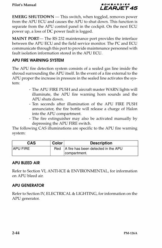
Pilot’s Manual
2-44 PM-126A
EMERG SHUTDOWN — This switch, when toggled, removes powerfrom the APU ECU and causes the APU to shut down. This function isseparate from the APU control panel in the cockpit. On the next ECUpower up, a loss of DC power fault is logged.
MAINT PORT— The RS 232 maintenance port provides the interfacebetween the APU ECU and the field service monitor. The PC and ECUcommunicate through this port to provide maintenance personnel withfault isolation information stored in the APU ECU.
APU FIRE WARNING SYSTEM
The APU fire detection system consists of a sealed gas line inside theshroud surrounding the APU itself. In the event of a fire external to theAPU proper the increase in pressure in the sealed line activates the sys-tem:
- The APU FIRE PUSH and aircraft master WARN lights willilluminate, the APU fire warning horn sounds and theAPU shuts down.
- Ten seconds after illumination of the APU FIRE PUSHannunciator, the fire bottle will release a charge of Haloninto the APU compartment.
- The fire extinguisher may also be activated manually bydepressing the APU FIRE switch.
The following CAS illuminations are specific to the APU fire warningsystem:
APU BLEED AIR
Refer to Section VI, ANTI-ICE & ENVIRONMENTAL, for informationon APU bleed air.
APU GENERATOR
Refer to Section IV, ELECTRICAL & LIGHTING, for information on theAPU generator.
CAS Color DescriptionAPU FIRE Red A fire has been detected in the APU
compartment.
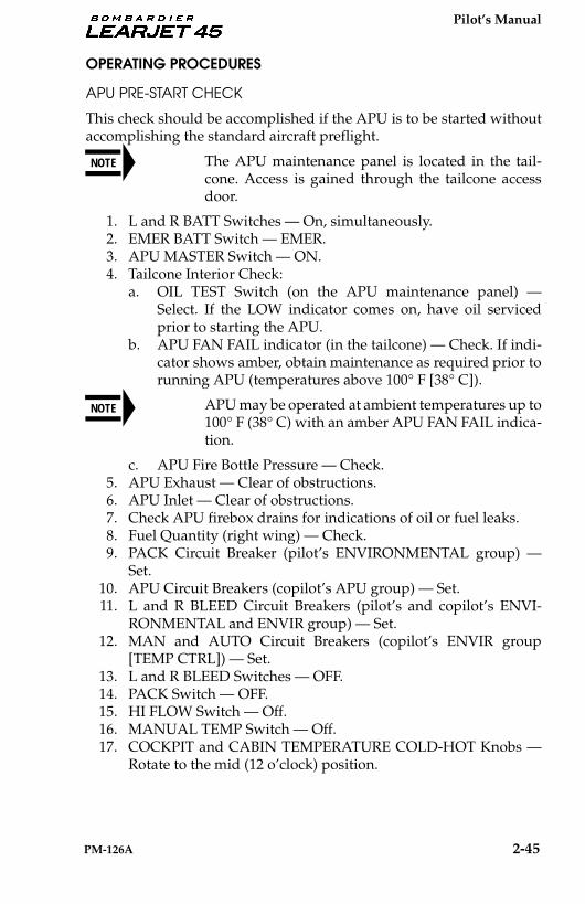
Pilot’s Manual
PM-126A 2-45
OPERATING PROCEDURES
APU PRE-START CHECK
This check should be accomplished if the APU is to be started withoutaccomplishing the standard aircraft preflight.
The APU maintenance panel is located in the tail-cone. Access is gained through the tailcone accessdoor.
1. L and R BATT Switches — On, simultaneously.2. EMER BATT Switch — EMER.3. APU MASTER Switch — ON.4. Tailcone Interior Check:
a. OIL TEST Switch (on the APU maintenance panel) —Select. If the LOW indicator comes on, have oil servicedprior to starting the APU.
b. APU FAN FAIL indicator (in the tailcone) — Check. If indi-cator shows amber, obtain maintenance as required prior torunning APU (temperatures above 100° F [38° C]).
APU may be operated at ambient temperatures up to100° F (38° C) with an amber APU FAN FAIL indica-tion.
c. APU Fire Bottle Pressure — Check.5. APU Exhaust — Clear of obstructions.6. APU Inlet — Clear of obstructions.7. Check APU firebox drains for indications of oil or fuel leaks.8. Fuel Quantity (right wing) — Check.9. PACK Circuit Breaker (pilot’s ENVIRONMENTAL group) —
Set.10. APU Circuit Breakers (copilot’s APU group) — Set.11. L and R BLEED Circuit Breakers (pilot’s and copilot’s ENVI-
RONMENTAL and ENVIR group) — Set.12. MAN and AUTO Circuit Breakers (copilot’s ENVIR group
[TEMP CTRL]) — Set.13. L and R BLEED Switches — OFF.14. PACK Switch — OFF.15. HI FLOW Switch — Off.16. MANUAL TEMP Switch — Off.17. COCKPIT and CABIN TEMPERATURE COLD-HOT Knobs —
Rotate to the mid (12 o’clock) position.
NOTE
NOTE
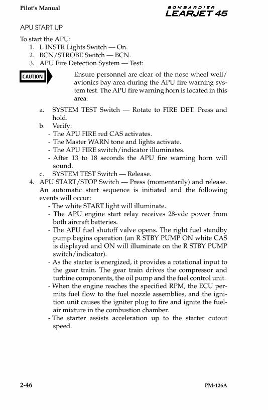
Pilot’s Manual
2-46 PM-126A
APU START UP
To start the APU:1. L INSTR Lights Switch — On.2. BCN/STROBE Switch — BCN.3. APU Fire Detection System — Test:
Ensure personnel are clear of the nose wheel well/avionics bay area during the APU fire warning sys-tem test. The APU fire warning horn is located in thisarea.
a. SYSTEM TEST Switch — Rotate to FIRE DET. Press andhold.
b. Verify:- The APU FIRE red CAS activates.- The Master WARN tone and lights activate.- The APU FIRE switch/indicator illuminates. - After 13 to 18 seconds the APU fire warning horn will
sound. c. SYSTEM TEST Switch — Release.
4. APU START/STOP Switch — Press (momentarily) and release.An automatic start sequence is initiated and the followingevents will occur:
- The white START light will illuminate.- The APU engine start relay receives 28-vdc power from
both aircraft batteries. - The APU fuel shutoff valve opens. The right fuel standby
pump begins operation (an R STBY PUMP ON white CASis displayed and ON will illuminate on the R STBY PUMPswitch/indicator).
- As the starter is energized, it provides a rotational input tothe gear train. The gear train drives the compressor andturbine components, the oil pump and the fuel control unit.
- When the engine reaches the specified RPM, the ECU per-mits fuel flow to the fuel nozzle assemblies, and the igni-tion unit causes the igniter plug to fire and ignite the fuel-air mixture in the combustion chamber.
- The starter assists acceleration up to the starter cutoutspeed.
CAUTION
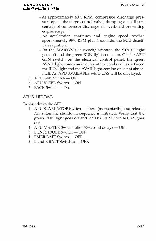
Pilot’s Manual
PM-126A 2-47
- At approximately 60% RPM, compressor discharge pres-sure opens the surge control valve, dumping a small per-centage of compressor discharge air overboard preventingengine surge.
- As acceleration continues and engine speed reachesapproximately 95% RPM plus 4 seconds, the ECU deacti-vates ignition.
- On the START/STOP switch/indicator, the START lightgoes off and the green RUN light comes on. On the APUGEN switch, on the electrical control panel, the greenAVAIL light comes on (a delay of 3 seconds or less betweenthe RUN light and the AVAIL light coming on is not abnor-mal). An APU AVAILABLE white CAS will be displayed.
5. APU GEN Switch — ON.6. APU BLEED Switch — ON.7. PACK Switch — On.
APU SHUTDOWN
To shut down the APU:1. APU START/STOP Switch — Press (momentarily) and release.
An automatic shutdown sequence is initiated. Verify that thegreen RUN light goes off and R STBY PUMP white CAS goesout.
2. APU MASTER Switch (after 30-second delay) — Off.3. BCN/STROBE Switch — OFF.4. EMER BATT Switch — OFF.5. L and R BATT Switches — OFF.
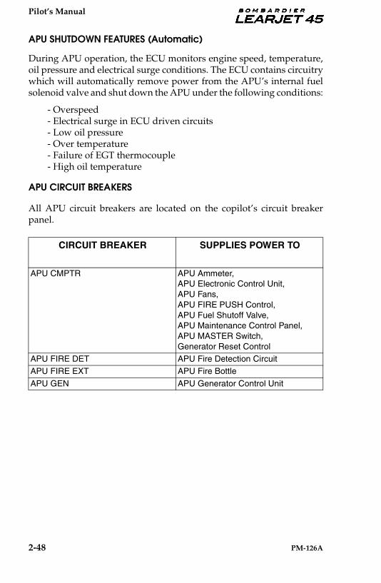
Pilot’s Manual
2-48 PM-126A
APU SHUTDOWN FEATURES (Automatic)
During APU operation, the ECU monitors engine speed, temperature,oil pressure and electrical surge conditions. The ECU contains circuitrywhich will automatically remove power from the APU’s internal fuelsolenoid valve and shut down the APU under the following conditions:
- Overspeed - Electrical surge in ECU driven circuits- Low oil pressure - Over temperature - Failure of EGT thermocouple- High oil temperature
APU CIRCUIT BREAKERS
All APU circuit breakers are located on the copilot’s circuit breakerpanel.
CIRCUIT BREAKER SUPPLIES POWER TO
APU CMPTR APU Ammeter,APU Electronic Control Unit,APU Fans, APU FIRE PUSH Control, APU Fuel Shutoff Valve,APU Maintenance Control Panel, APU MASTER Switch, Generator Reset Control
APU FIRE DET APU Fire Detection Circuit APU FIRE EXT APU Fire Bottle
APU GEN APU Generator Control Unit