bond graph for modelling, analysis, control design, fault diagnosis geneviève dauphin-tanguy...
Post on 22-Dec-2015
216 views
TRANSCRIPT
Bond Graph for Modelling, Analysis,Control Design, Fault Diagnosis
Geneviève Dauphin-Tanguy
Christophe SueurLaboratoire d’Automatique et d’Informatique Industrielle de Lille
Bond Graph Research GroupLaboratoire d’Automatique et d’Informatique Industrielle de Lille
Ecole Centrale de Lille
• 6 academics (2 Profs, 2 associate profs, 2 assistant profs)
• 10 PhD students
Application areas : power systems (electrical machines, photovoltaic systems, fuel cells), thermofluid process, car industry

Rosario - 22/11/02 LAIL - Ecole Centrale de Lille 3
Studies performed in collaboration with Peugeot -Citroën
• Mechatronic design of an automatic gear box
• Clutch management and drive comfort
• Mechatronic design of an active hydraulic suspension
• Thermal comfort regulation in a car interior
• Modelling and simulation of a fuel cell system
• Analysis of structural properties of bond graph models
• Robustness of control laws for systems with parametric uncertainties
• …..

Rosario - 22/11/02 LAIL - Ecole Centrale de Lille 4
Why a bond graph approach ?
• Multidisciplinary systems need for a communication language between people from different physical domains
• Need for models with physical insight (virtual testing facility)
• Unified modelling methodology for knowledge storage in model libraries
• Integrated (« mechatronic ») design of controlled systems

Rosario - 22/11/02 LAIL - Ecole Centrale de Lille 5
Mechatronic design
Modelling Control
Diagnosis
IdentificationAnalysisValidationSimulation
SimplificationActuatorsSensors
Fault Detection andIsolation
Objectives
Faulty modeMaintaining

Rosario - 22/11/02 LAIL - Ecole Centrale de Lille 6
1 - Mechatronic design of an automatic gear box
engine torqueconverte
r
automatic
gear box
vehicle
computer
Differential, Transmission shaftWheels, Vehicle mass, air resistance, road friction
Complete driveline

Rosario - 22/11/02 LAIL - Ecole Centrale de Lille 7
1 - Mechatronic design of an automatic gear box
Problem statement
• Design control laws for the driving of an automatic gear box by a computer with the following objectives:– Complete satisfaction of the customer corresponding to a variation
of the engine torque as continue as possible
(no jerk in acceleration during a shift)
– Respect of technological constraints (actuator response duration, minimization of the energy dissipated in the clutchs)
When to shift ? How to shift ?

Rosario - 22/11/02 LAIL - Ecole Centrale de Lille 8
1 - Mechatronic design of an automatic gear box
Automatic gear box : physical scheme
Arrangement of 2 epicyclic gear trains which allows 3 ratios plus one reverse
Different ratios : one element blockedor 2 elements maintained at the same speed
Clutches between 2 rotating elementsBrakes between one element and the housing block
Planetcarrier
ring
Planet
mPCP
PCR

Rosario - 22/11/02 LAIL - Ecole Centrale de Lille 9
1 - Mechatronic design of an automatic gear box
Bond graph model of the automatic gear box
:Jinp
:friction:PC1_R2
:P1
:PC2
:housing
:m2
:1-m2
:1-m1
:m1
:R1
:input
:load
clutch 2
:housing
Clutch1
brake 2
brake 1
Free wheel

Rosario - 22/11/02 LAIL - Ecole Centrale de Lille 10
1 - Mechatronic design of an automatic gear box
Bond graph model of a clutch or a brake
:pressure:friction_coeff
Coulomb friction depending on the pressure applied on the clutch disks, defining the « limited torque »
torque
slip
pressure
If clutch torque < limited torque clutch closed, all the torque transmittedIf clutch torque = limited torque clutch opened, slipping velocity

Rosario - 22/11/02 LAIL - Ecole Centrale de Lille 11
1 - Mechatronic design of an automatic gear box
Decision block
Contains the schift schedule (diagram throttle position vs vehicle speed) which permits to know « when to shift »
Different programs: economical, sport, snow
When a shift is decided, the different pressures in the clutches are controlled
pressure
time
« How to shift » : - action on only 2 clutches or 2 brakes at the same time,- control of the pressure to have a smooth shift
and no jerk in acceleration

Rosario - 22/11/02 LAIL - Ecole Centrale de Lille 12
1 - Mechatronic design of an automatic gear box
Bond graph model of the vehicle
differential
: AGB outputtorque
:Cwheel_r:Jwheel_r:Cshaft_r
:Cwheel_l:Cshaft_l:Jshaft_l
:air_friction
:Mveh
:Jwheel_l
:rwh_2
:rwh_1
:slope
:Jshaft_r
left_shaft left_wheelvehicle
right_wheel
right_shaft
:Idiff
:diff
Rosario - 22/11/02 LAIL - Ecole Centrale de Lille 13
2- Clutch management and drive comfort
• Ojectives: – Reduce the well-known fore and aft oscillation of a vehicle
occuring when a sudden torque variation takes place in the transmission (throttle step sollicitation)
– Satisfy comfort and driving pleasure
• Means:– Define an hydraulic-electronic-mechanical actuator transforming
the numerical output into pressure on the plates of the clutch
– Design control laws for this electrohydraulic servovalve
Rosario - 22/11/02 LAIL - Ecole Centrale de Lille 14
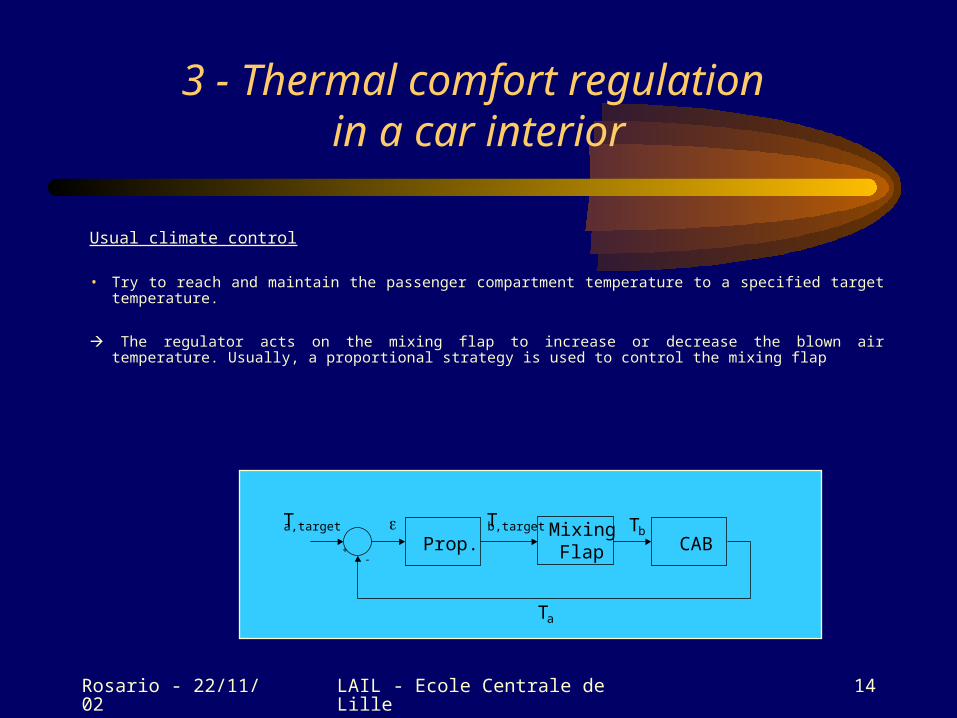
3 - Thermal comfort regulation in a car interior
Usual climate control
• Try to reach and maintain the passenger compartment temperature to a specified target temperature.
The regulator acts on the mixing flap to increase or decrease the blown air temperature. Usually, a proportional strategy is used to control the mixing flap
CABMixing
FlapProp.+-
Tb,target Tb
Ta
Ta,target

Rosario - 22/11/02 LAIL - Ecole Centrale de Lille 15
3 - Thermal comfort regulation in a car interiorUsual climate control
! Usually the air temperature in the compartment does not reach the target temperature.
0 500 1000 1500
-10
-5
0
5
10
15
20
25
temps(s)
Tha
b(°C
)
Tcons
Text = -10°C
heating
0 500 1000 150018
19
20
21
22
23
24
25
temps(s)
Tha
b(°C
)Tcons
Text = 25°C
cooling)

Rosario - 22/11/02 LAIL - Ecole Centrale de Lille 16
3 - Thermal comfort regulation in a car interiorComfort strategy
• comfort : much more than only thermal comfort. Our five senses, our cerebral state, our thermal state have an influence on our comfort estimating.
• thermal sensations rather than thermal comfort - a very subjective notion.
• in PSA Peugeot-Citroën, quantitative scale to evaluate a thermal sensation : an integer between 1 (very cold) and 9 (very hot) sensation.
Objectives: define a regulation strategy for a climate controller for car interior, taking
into account the car passenger's thermal sensations.

Rosario - 22/11/02 LAIL - Ecole Centrale de Lille 17
3 - Thermal comfort regulation in a car interiorBlock representation of the model
climaticconditions
ACTUATORS
recycling flap
thermalcar
interiormodel
air temperaturewalls temperature
air speed
interiorgeometry
materialsproperties
drivingconditions
mixing flap
compressor on/offblower tension
spreading air flaps
e
activity
physiologicalmodel thermal
feelings
clothes
SENSORSREGULATOR

Rosario - 22/11/02 LAIL - Ecole Centrale de Lille 18
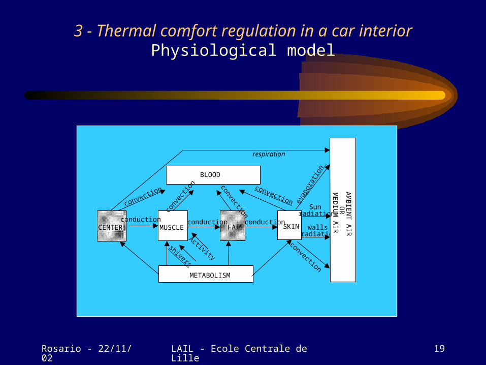
3 - Thermal comfort regulation in a car interiorPhysiological model
human body divided into seven parts called segments: the head, the trunk, the left arm, the right arm, the hands, the legs and the feet.
head and hands segments are bare.
fat
center
muscle
skin
air
clothes
center
muscle
fatskin
bare segment dressed segment
Rosario - 22/11/02 LAIL - Ecole Centrale de Lille 19
3 - Thermal comfort regulation in a car interiorPhysiological model
CENTER MUSCLE FAT SKIN
BLOOD
conduction conduction conduction
convection
conv
ectio
n convection
convection evap
orat
ion
wallsradiation
METABOLISM
AM
BIE
NT
AIR
OR
ME
DIU
M A
IR respiration
shivers
Activity
Sunradiation
convection

Rosario - 22/11/02 LAIL - Ecole Centrale de Lille 20
For each segment
3 - Thermal comfort regulation in a car interiorPhysiological model
to the fat
Sf :Qsh (m)
1
R
0
T(m)Td (m)
To th
ebl
ood
1B
cR
C:C
(m)
Td (c)
Sf:Qa (m
)SfQb(m)
Muscle layer
0
Tblood
C: Cblood
Bc(c)
Bc(f
)
Bc(s)
Bc(m
)
Blood layer

Rosario - 22/11/02 LAIL - Ecole Centrale de Lille 21
3 - Thermal comfort regulation in a car interiorPhysiological mathematical model
• x state vector (order = 57) : temperature, water mass, sudation production and water partial pressure of the layers.
• u input vector (size = 14) : air temperature and air speed of the ambient air close to the 7 segments.
• d disturbance vector (size = 35) : ambient air humidity, sun and wall radiation on clothes and skin layers.
• y output vector (size = 7) : thermal feelings of the 7 segments.
),,(
),,(
duxgy
duxfx

Rosario - 22/11/02 LAIL - Ecole Centrale de Lille 22
3 - Thermal comfort regulation in a car interiorLinearized physiological mathematical model
• A nominal functioning point defined as a comfortable situation for the human (air temperature=299K, air speed=0.5m/s and humidity=50%).
• Two linear models containing saturations, because heat transfers are different whether the body is warm or cold.
– b = 1 if the body is cold, and 0 if not.
– F vector that results from constant thresholds due to saturations.
– K matrix selecting the x components concerning the saturations.
MxKm
uDxCy
FdEuBxAbbAx wc )(

Rosario - 22/11/02 LAIL - Ecole Centrale de Lille 23
3 - Thermal comfort regulation in a car interiorPhysiological model : simplifications
0 1000 2000 3000 4000 5000 6000 7000 80004.55
4.6
4.65
4.7
4.75
4.8comparison of order 57 and order 9 linear models
time(s)
trun
k se
nsat
ion
order 57 model
order 9 model
0 1000 2000 3000 4000 5000 6000 7000 8000 32.8
33
33.2
33.4
33.6
33.8
34
34.2
34.4
34.6 comparison of linear and non-linear
models
time (s)
tru
nk
ski
n
te
mp
er
atu
re
(°
C)
non linear model
linear model
air temperature=22°C
air humidity=50%
air speed=0.1m/s
Trunk sensationsTrunk skin temperature
Rosario - 22/11/02 LAIL - Ecole Centrale de Lille 24
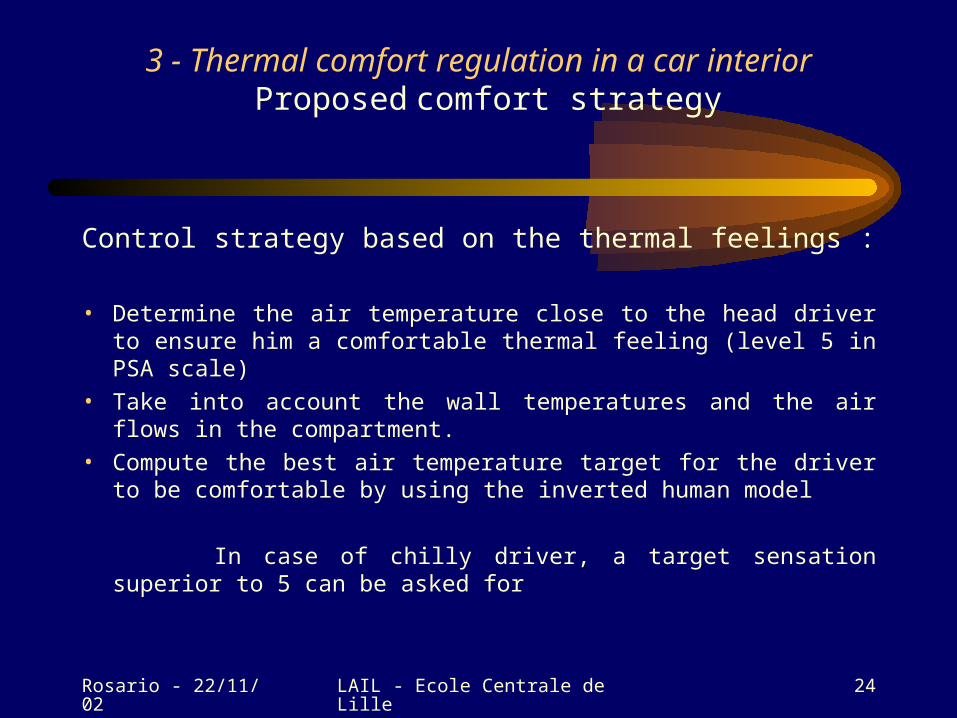
3 - Thermal comfort regulation in a car interior Proposed comfort strategy
Control strategy based on the thermal feelings :
• Determine the air temperature close to the head driver to ensure him a comfortable thermal feeling (level 5 in PSA scale)
• Take into account the wall temperatures and the air flows in the compartment.
• Compute the best air temperature target for the driver to be comfortable by using the inverted human model
In case of chilly driver, a target sensation superior to 5 can be asked for

Rosario - 22/11/02 LAIL - Ecole Centrale de Lille 25
3 - Thermal comfort regulation in a car interior Proposed comfort strategy
Thermalfeelings
MixingFlap
Cab HumanRegulatorInvertedhuman
Wall temp.model
Air temp.model
Tb,target TbThermalfeelingstarget
Ta,target
Ta
Twall
Tair,model
+
-
Predictive control (GPC)

Rosario - 22/11/02 LAIL - Ecole Centrale de Lille 26
3 - Thermal comfort regulation in a car interior Comfort strategy - Air temperature model
linear convex formulation:
• Ta air temperature,
• Tout outside air temperature,
• Tb blown air temperature,
convex parameter depending essentially of the blown air flow and the vehicle speed.
There are two dynamic modes : a fast mode caused by the mass transfer
and a slow mode caused by the thermal transfers with the outside.
baoutaa TTss
T )1()(1
1
1(
21

Rosario - 22/11/02 LAIL - Ecole Centrale de Lille 27
3 - Thermal comfort regulation in a car interior Comfort strategy - Wall temperature model
first order model:
• Tw the surface temperature,
• Ta the air compartment temperature close to the surface.
Experiments in a wind tunnel to identify the parameters of each air temperaturemodel and wall temperature model : several wind-tunnel air flows (for the air flow due to the vehicle speed), severaloutside temperatures, several blown air temperatures and flows
))1()(1
1( awoutw
ww TT
sT
Rosario - 22/11/02 LAIL - Ecole Centrale de Lille 28
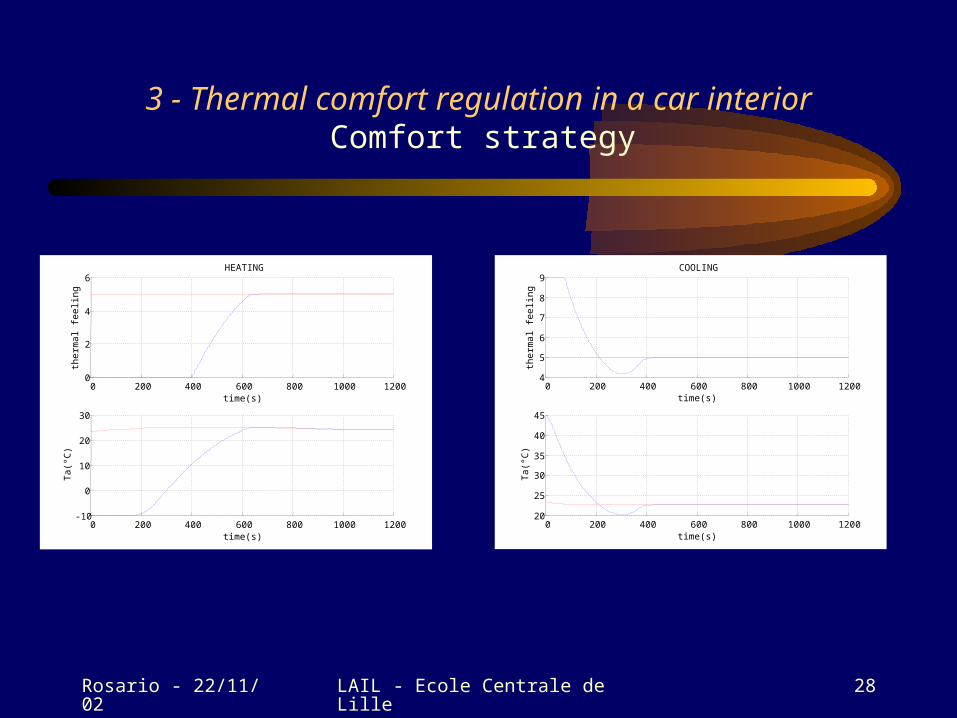
3 - Thermal comfort regulation in a car interior Comfort strategy
0 200 400 600 800 1000 12000
2
4
6
time(s)
ther
mal
fee
ling
HEATING
0 200 400 600 800 1000 1200-10
0
10
20
30
time(s)
Ta(
°C)
0 200 400 600 800 1000 12004
5
6
7
8
9
time(s)
ther
mal
fee
ling
COOLING
0 200 400 600 800 1000 120020
25
30
35
40
45
time(s)T
a(°C
)

Rosario - 22/11/02 LAIL - Ecole Centrale de Lille 29
4 – Modelling of a fuel cell system
FuelCell
engine
Ui
reforming
recoveringrecycling
Compressor
Humidifier
Compressorair
2H
air
2Hhumid
?maxP
)
, (
methanol
gaznatural
fuel

Rosario - 22/11/02 LAIL - Ecole Centrale de Lille 30
4 – Modelling of a fuel cellFuel cell : principle
load
anode cathodeelectrolyte
2O
e
2O2H
eOHOH 222
2 2
221 2 OeO

Rosario - 22/11/02 LAIL - Ecole Centrale de Lille 31
4 – Modelling of a fuel cellFuel cell : tubular design
Fuel flow(hydrogen)
post combustion
air
interconnect
interconnect
anode
cathode
electrolyte
electrolyte
air,e
fuel,i fuel,o
air,s
Reaction zone
Anode canal
Cathode canal
anode active layer
Cathode active layer
Anode diffusion zone
Cathode diffusion layer
gaz,diffa
air,diffc
Q
productedOvH 2
½ anode interconnect
½ cathode i nterconnect
1
1
2
2
environment
mesh 2mesh 1

Rosario - 22/11/02 LAIL - Ecole Centrale de Lille 32
4 – Modelling of a fuel cellVariables
Pressure:
Temperature:
Mass or molar flow rate:
Enthalpy flow
Fluid
TcmH p..
nm or
TP
Molar flow rate:
Chemical potential : Chemical reaction
n
Current:
Voltage: Electrical
U
i

Rosario - 22/11/02 LAIL - Ecole Centrale de Lille 33
electrolyte
cathode+
Cathodecanal
+interconnect
anode+
anodecanal
+interconnect
,consOn2
,consHn2
Ov,prodHn
2
gaz,em
gaz,eHair,eH
air,em
iU
HMSfHMSf
TMSfTMSf
eairm ,
eairT ,
sairT , sgazT ,sairm , sgazm ,
extP extP
MSe MSe
load
extP extP
aohmQ ,
elaohmQ ,
elcohmQ ,
eohmQ ,
cohmQ ,
gfT
wfT environt
gfT
wfTenviront
SeSe
extT
extT
MSe
extT
MSe
extT
Electro-chemical reaction
FC Word BG

Rosario - 22/11/02 LAIL - Ecole Centrale de Lille 34
Anodeintercon
nect
Anodeactivelayer
anodediffusion
zone Anodecanal
Electrochemicalréaction
Ov,prodHn2
,consHn2
aohmQ ,
Ov,diffaHn2
Ar,diffan
,diffaHn2
diffaQdiffaQ
,diffaHn2
Ar,diffan
Ov,diffaHn2
gaz,sm
gaz,eH
gaz,em
,consOn2
diffaOv,prodHn .2 diffaOv,prodHn .2
iU
diffagazH ,
diffagazH ,
sgazT ,extP
pbaQ
gfT
wfT
Electrolyte
elaohmQ ,
extT
FC AnodeWord BG

Rosario - 22/11/02 LAIL - Ecole Centrale de Lille 35
anodeJ-th diffusion zone
jth anodeinterconnect
C
0
0
0
0
ejHn ,2
ejOvHn ,2
ejArn ,
cnlajHn ,2
diffajHn ,2
cnlajOvHn ,2
diffajOvHn ,2
cnlajArn ,
difafjArn ,
cnlaj
ejgazm ,
ejgazH ,
dpbajQ
sjHn ,2
sjArn ,
sjOvHn ,2
diffajgazH ,
*
,2 cnlajHP
*
,cnlajArP
*
,2 cnlajOvHP
cnlajgazH ,
cnlajT
sjgazm ,
icnlaji Mx ,,ieji Mx ,,
diffajQ
sjgazH ,
cnlajP
diffajprodOvHn .,2
cnlajT222
. . ,,, HejHejgazejH Mxmn
ejgazm ,Fuel supply
Anode canalBG

Rosario - 22/11/02 LAIL - Ecole Centrale de Lille 36
0
0
0,diffajHn
2
,ejHn2
,sjHn2
diffajOv,prodHn .2
Ov,ejHn2
Ar,ejnOv,sjHn
2
*
2Ov,cnlajHP
*Ar,cnlajP
Ar,sjnAr,diffajn
ii,cnlaj Mx ,
gazjgaz,s mm ou
pdcjR
)1(ou jcnlaext PP
*
2 ,cnlajHP
egazm ,
0
sgazH ,
diffajQ )1(, ou jgazegaz HH
)1(ou ji,cnlai,e xxC
Ov,cnlajHn2
Ar,cnlajn,cnlajHn
2
cnlajgazH ,
cnlajT
Ov,diffajHn2
cnlajC
cnlajP
diffajgazH ,
R1
1
1
1
1
diffajR
1
0
0
0
prodjOvHn ,2
ajohmQ ,
0
Ov,diffajHn2
diffajQ
,diffajHn2
Ar,diffajn
caajH
,caajHn2
Ov,caajHn
2Ar,caajn
diffajOv,prodHn .2
caajC
caajT
caajH ,2
caajAr ,
caajOvH ,2
diffajgazH ,
C
1
1
1
1
1
1
Electrochemichal
reaction
caajH ,2
caajOvH ,2
caajAr ,
caajT
caajOvH ,2
caajT
*,2 cnlajHP
*,2 cnlajOvHP
*,cnlajArP
cnlajT
*,2 cnlajOvHP
electrolyte
elajohmQ ,
dpbajQ
1 thermjRgazjsgaz mm ou ,
meshlast if gaz,sm meshlast if gaz,sT
gazjHou
)1(, jgazm
ou
consjHn ,2
)1(ou jcnlaext TT
environmentor
mesh (j+1)

Rosario - 22/11/02 LAIL - Ecole Centrale de Lille 37
1
1
cathodeactivelayer
anodeactivelayer
caaT
,consOn2
cacOμ ,2 caaHμ ,2
caaOvHμ ,2
Ov,prodHn2
TFOvH2
TFFne
TFH2
/1 TF
O2/1
loadi
U
vΔG
E i
aohmQ ,
,consHn2
pol Rpol
RScR
ohmi
i
RScR
RSelR
electrolyteelohmQ ,
cohmQ ,
Rdiff
diff
Electrochemical reaction

Rosario - 22/11/02 LAIL - Ecole Centrale de Lille 38
anodeDiffusion zone j
interconnectanode j
C
0
0
0
0
ejHn ,2
ejOvHn ,2
ejArn ,
cnlajHn ,2
diffajHn ,2
cnlajOvHn ,2
diffajOvHn ,2
cnlajArn ,
difafjArn ,
cnlaj
ejgazm ,
ejgazH ,
dpbajQ
sjHn ,2
sjArn ,
sjOvHn ,2
diffajgazH ,
*
,2 cnlajHP
*
,cnlajArP
*
,2 cnlajOvHP
cnlajgazH ,
cnlajT
sjgazm ,
icnlaji Mx ,,ieji Mx ,,
diffajQ
sjgazH ,
cnlajP
diffajprodOvHn .,2
cnlajT
BG to Simulink

Rosario - 22/11/02 LAIL - Ecole Centrale de Lille 39
4 – Modelling of a fuel cellResults
Complete dynamic model of the fuel cell system (no similar result in the literature, only static models)
Simulation results validated by comparison with experimental data
Work with PSA is running for:Control designing : how to maximize the power delivered by the
fuel cell systemFault diagnosis
Rosario - 22/11/02 LAIL - Ecole Centrale de Lille 40
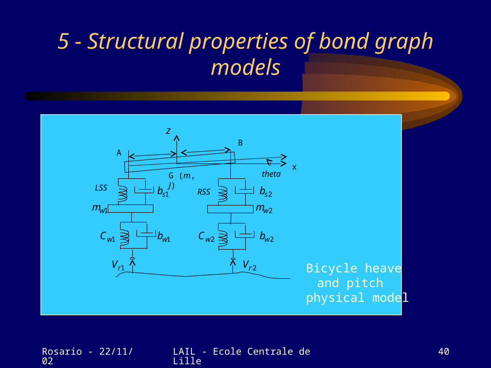
5 - Structural properties of bond graph models
LSS
1wb1wC
1wm
2wb
1sb 2sb
2wm
2wC
1rV 2rV
G (m, J) theta
AB
x
RSS
z
Bicycle heave and pitch
physical model

Rosario - 22/11/02 LAIL - Ecole Centrale de Lille 41
5 - Structural properties of bond graph models
R : I : J
0 0
1
1
I : m
TF TF
I :
1
1 0
1
C : LSS 1
0
1
1
C : RSS
I :
Se :
R :
Sf :
C :
Sf : R :
0 101
R :
C :
1wb
1wC
1wm
2wb
1sb 2sb2wm
2wC
1rV 2rV
mtF
Bicycle heave and pitch BG model

Rosario - 22/11/02 LAIL - Ecole Centrale de Lille 42
5 - Structural properties of bond graph modelsPassive model
• State equation
EdAxx
ermasstransfFd1
2
12
roadVroadV
d
ntsdisplaceme spring
impulses inertia
C
I
q
px
2
1
d
dd

Rosario - 22/11/02 LAIL - Ecole Centrale de Lille 43
5 - Structural properties of bond graph modelsPassive model
• State equation
• order n of a model : number of I and C elements in integral causality when a preferred integral causality is assigned to the bond graph model
• BG-rank q of the state space matrix A : number of I and C elements in derivative causality when a preferred derivative causality is assigned to the bond graph model.
• number of structurally null modes of A-matrix : number of I and C elements which have to stay in integral causality when a preferred derivative causality is assigned to the bond graph model
EdAxx
Rosario - 22/11/02 LAIL - Ecole Centrale de Lille 44
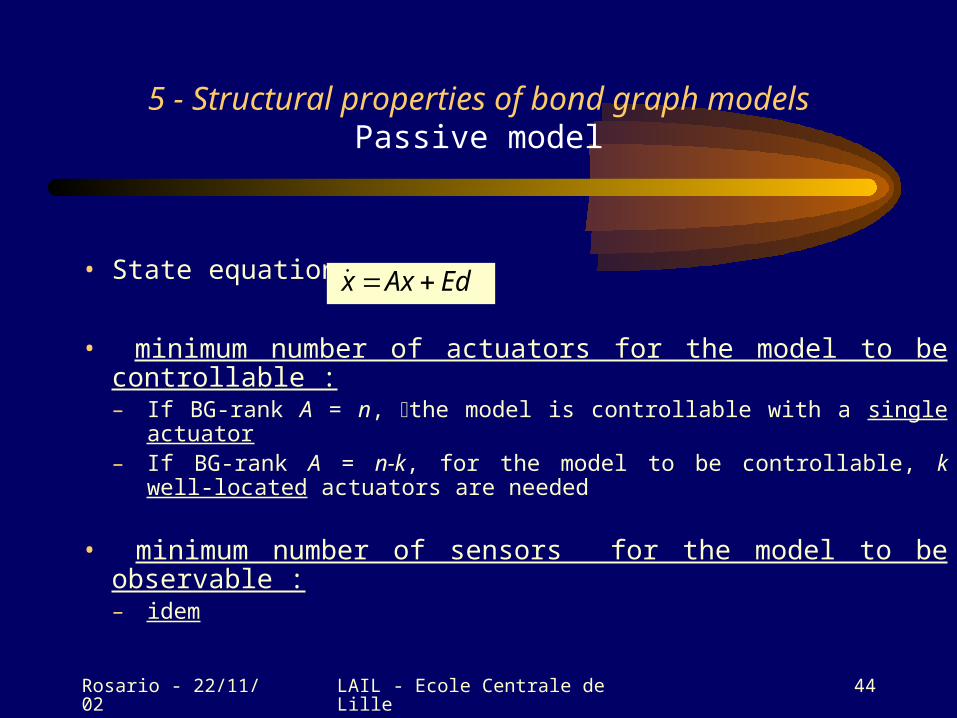
5 - Structural properties of bond graph modelsPassive model
• State equation
• minimum number of actuators for the model to be controllable :– If BG-rank A = n, the model is controllable with a single actuator– If BG-rank A = n-k, for the model to be controllable, k well-located
actuators are needed
• minimum number of sensors for the model to be observable :– idem
EdAxx
Rosario - 22/11/02 LAIL - Ecole Centrale de Lille 45
5 - Structural properties of bond graph models Design of the measurement and control architecture for the
active system
• definition of the control objectives– what variables to be controlled?
– for what performances (dynamical or frequential criteria)?
– with what strategy (pole placement, disturbance rejection, …)?
• what type of control law? – state feedback?
• Is the state measurable?
– output feedback?

Rosario - 22/11/02 LAIL - Ecole Centrale de Lille 46
5 - Structural properties of bond graph models Design of the measurement and control architecture for
the active system
Choice here
State feedback for pole placement and rejection of the disturbance corresponding to the mass transfer due to driver actions (braking or accelerating) on the 2 velocity variables (heave and pitch)
! the 2 variables (absolute velocities) to be controlled are not measurable
an observer is needed
! We want to perform input/output decoupling
2 control inputs are needed

Rosario - 22/11/02 LAIL - Ecole Centrale de Lille 47
5 - Structural properties of bond graph models Design of the measurement and control architecture for
the active system
2 outputs to be controlled : not measurable (Df*)
measurement vector (Df)
2 control inputs (MSe)
disturbance vector
measurable to be rejected (Se) non- measurable (Sf)
J
mV
y
yy
2
1
2
1
2
1
rel
relV
V
z
zz
2
1
2
1
actFactF
u
uu
ermasstransfFd1
2
12
roadVroadV
d

Rosario - 22/11/02 LAIL - Ecole Centrale de Lille 48
5 - Structural properties of bond graph models Design of the measurement and control architecture for
the active system
Df :
R :
Df* :
I : J
0 0
1
1
I : m
TF TF
I :
1
1 0
1
C : LSS 1
0
1
1
C : RSS
I :
Se :
Df :
R :
Sf :
C :
Sf : R :
0 101
R :
C :
MSe :
1wb
1wC
1wm
2wb
1sb 2sb2wm
2wC
1rV 2rV
2aF
mV
1sV2sV
mtF
Df* : JMSe:
1aF

Rosario - 22/11/02 LAIL - Ecole Centrale de Lille 49
Conclusion
* bond graph : language quite « strange » which needs a learning time
* Could appear difficult to implement, but
what is difficult is PHYSICS
* more and more introduced in the industrial world in France (better than in the academic world!)