bond-rite remote ii - newson gale...api rp 2003. note: the bond-rite is designed to prevent the...
TRANSCRIPT

READ MANUALBEFORE COMMENCINGWITH INSTALLATION
Installation & Operating Instructions
Bond-Rite REMOTE II
cCSAus Version
The safety of any system incorporating the equipment referred to in this manual is the responsibility of the installer of the system.
If the equipment is used in a manner not specified by the manufacturer, the protection provided by the equipment may be impaired.
Any warranty is made void if the equipment is not installed, or used, in accordance with the manufacturers instructions.
®
www.newson-gale.com
US

The following special checking or maintenance
conditions are required for the safe operation of
the equipment:
The LED flashes when the clamp is operating
correctly and is monitoring a good bonding
connection.
If the LED does not flash when the clamp is
attached to a conductive item then it should be
checked as follows:-
Check the condition of all associated cable
terminations. Adjust as necessary.
Connect the clamp onto a clean piece of metal.
The LED should now flash.
Use the correct tool to remove the screws which
retain the pcb housing lid.
Due to the design of the Ultralife U9VL-J battery,
and
Varta 6122 E-Block battery, it can be replaced in
the hazardous area.
Carefully remove the battery and replace with an
Ultralife U9VL-J or Varta 6122 E-Block battery.
If the LED still fails to show please contact
Newson Gale for further advice.
The replacement battery shall be an Ultralife
U9VL-J or Varta 6122 E-Block battery only. This
battery is intrinsically safe and may be replaced
when the equipment is in a hazardous area. The
battery must be removed when the equipment is
externally powered. Always keep the terminal
cover cap fitted until the battery is fitted into the
Bond-Rite REMOTE II.
If the LED does not flash replace the battery in
accordance with the instructions.
Again connect the clamp onto a clean piece of
metal. The LED should now flash.
Replace the housing lid and replace the screws.
Components to be incorporated into or used as
replacements in equipment have been so
designed and constructed that they function
safely for their intended purpose of explosion
protection when they are installed in accordance
with the manufacturer's instructions.
Battery Replacement (Battery Powered
Model)
The Bond-Rite REMOTE lead must have a connection
to ground in order to dissipate static electricity.Attach the Dual Circuit clamp to the item to be
grounded or bonded (drum, IBC, bucket etc.).
If the LED does not flash the connection resistance is
too high. Check the placement of the clamp to ensure
a good positive connection.
If the connection is good (less than 10 Ohms loop
resistance) then the green LED lamp should flash at a
rate of about 1 flash per second.
For battery information contact Newson Gale.
Battery Powered Model
The Bond-Rite REMOTE clamp is not designed to be
permanently connected.
Operation
The battery life is approximately 1 year with intermittent
use, and 28 days continuous use.
The grounding clamp should be fitted prior to any
other operation as per the recommendations of IEC TS
60079-32-1, CLC/TR: 60079-32-1, NFPA 77 and
API RP 2003.
Note: The Bond-Rite is designed to prevent the build
up of an incendive electrostatic charge during a mixing
or transfer operation. Care should be taken to ensure
that there is no static charge built up on the item before
attaching the clamp.
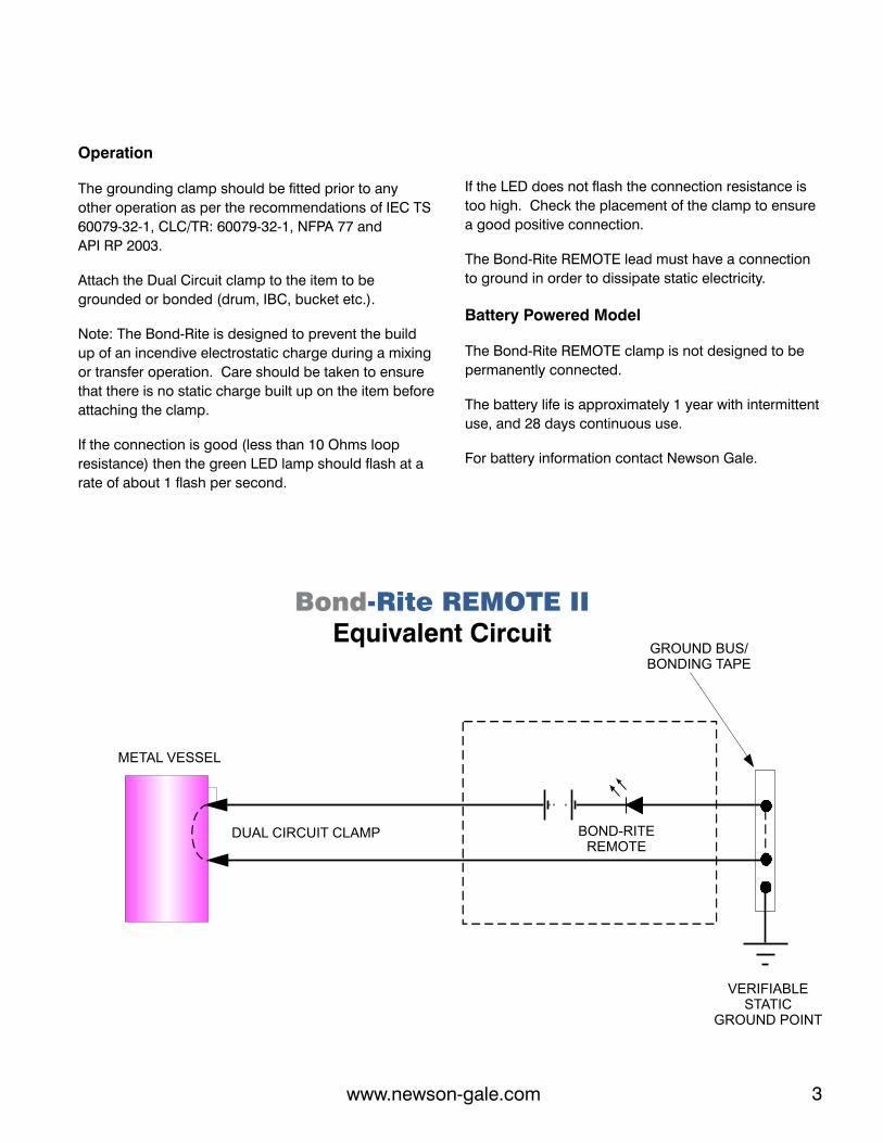
Bond-Rite REMOTE IIEquivalent Circuit
METAL VESSEL
DUAL CIRCUIT CLAMP
GROUND BUS/BONDING TAPE
VERIFIABLE STATIC
GROUND POINT
BOND-RITEREMOTE
Bond-Rite REMOTE II
www.newson-gale.com2 3www.newson-gale.com
The words “Earth” and “Ground” have the same meaning when used within this manual.
The system monitors the static dissipation path, from the object to which the Static
Grounding Clamp or lead is connected to, as far as the Static Grounding Point.
This Grounding Point should be close to the working area. It is the responsibility of
the end user to provide the Static Grounding Point and ensure that it is suitable for
dissipating electrostatic charges. Reference to NFPA70 Code of Practice, API RP
2003, IEC TS 60079-32-1, CLC/TR: 60079-32-1, or other applicable international
standard, will give guidance on the installation of a suitable Static Grounding Point.
The above does not apply to any system used to monitor a bond connection only.
Verification of the Static Grounding Point
IF YOU HAVE ANY QUERIES REGARDING THE ABOVE POINTS THEN PLEASE
CONTACT NEWSON GALE WITHOUT DELAY.
The following special checking or maintenance
conditions are required for the safe operation of
the equipment:
The LED flashes when the clamp is operating
correctly and is monitoring a good bonding
connection.
If the LED does not flash when the clamp is
attached to a conductive item then it should be
checked as follows:-
Check the condition of all associated cable
terminations. Adjust as necessary.
Connect the clamp onto a clean piece of metal.
The LED should now flash.
Use the correct tool to remove the screws which
retain the pcb housing lid.
Due to the design of the Ultralife U9VL-J battery,
and
Varta 6122 E-Block battery, it can be replaced in
the hazardous area.
Carefully remove the battery and replace with an
Ultralife U9VL-J or Varta 6122 E-Block battery.
If the LED still fails to show please contact
Newson Gale for further advice.
The replacement battery shall be an Ultralife
U9VL-J or Varta 6122 E-Block battery only. This
battery is intrinsically safe and may be replaced
when the equipment is in a hazardous area. The
battery must be removed when the equipment is
externally powered. Always keep the terminal
cover cap fitted until the battery is fitted into the
Bond-Rite REMOTE II.
If the LED does not flash replace the battery in
accordance with the instructions.
Again connect the clamp onto a clean piece of
metal. The LED should now flash.
Replace the housing lid and replace the screws.
Components to be incorporated into or used as
replacements in equipment have been so
designed and constructed that they function
safely for their intended purpose of explosion
protection when they are installed in accordance
with the manufacturer's instructions.
Battery Replacement (Battery Powered
Model)
The Bond-Rite REMOTE lead must have a connection
to ground in order to dissipate static electricity.Attach the Dual Circuit clamp to the item to be
grounded or bonded (drum, IBC, bucket etc.).
If the LED does not flash the connection resistance is
too high. Check the placement of the clamp to ensure
a good positive connection.
If the connection is good (less than 10 Ohms loop
resistance) then the green LED lamp should flash at a
rate of about 1 flash per second.
For battery information contact Newson Gale.
Battery Powered Model
The Bond-Rite REMOTE clamp is not designed to be
permanently connected.
Operation
The battery life is approximately 1 year with intermittent
use, and 28 days continuous use.
The grounding clamp should be fitted prior to any
other operation as per the recommendations of IEC TS
60079-32-1, CLC/TR: 60079-32-1, NFPA 77 and
API RP 2003.
Note: The Bond-Rite is designed to prevent the build
up of an incendive electrostatic charge during a mixing
or transfer operation. Care should be taken to ensure
that there is no static charge built up on the item before
attaching the clamp.
Bond-Rite REMOTE IIEquivalent Circuit
METAL VESSEL
DUAL CIRCUIT CLAMP
GROUND BUS/BONDING TAPE
VERIFIABLE STATIC
GROUND POINT
BOND-RITEREMOTE
Bond-Rite REMOTE II
www.newson-gale.com2 3www.newson-gale.com
The words “Earth” and “Ground” have the same meaning when used within this manual.
The system monitors the static dissipation path, from the object to which the Static
Grounding Clamp or lead is connected to, as far as the Static Grounding Point.
This Grounding Point should be close to the working area. It is the responsibility of
the end user to provide the Static Grounding Point and ensure that it is suitable for
dissipating electrostatic charges. Reference to NFPA70 Code of Practice, API RP
2003, IEC TS 60079-32-1, CLC/TR: 60079-32-1, or other applicable international
standard, will give guidance on the installation of a suitable Static Grounding Point.
The above does not apply to any system used to monitor a bond connection only.
Verification of the Static Grounding Point
IF YOU HAVE ANY QUERIES REGARDING THE ABOVE POINTS THEN PLEASE
CONTACT NEWSON GALE WITHOUT DELAY.

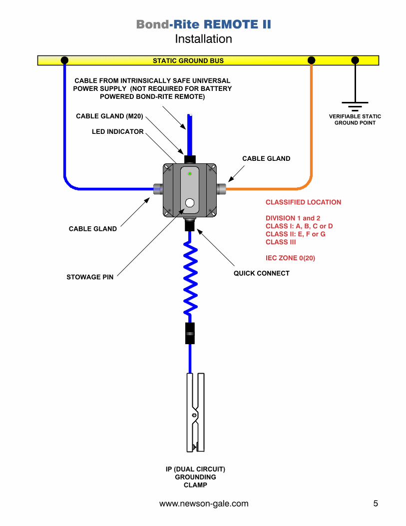
Bond-Rite REMOTE IIInstallation
VERIFIABLE STATICGROUND POINT
IP (DUAL CIRCUIT) GROUNDING
CLAMP
STOWAGE PINQUICK CONNECT
LED INDICATOR
CABLE GLAND
CABLE FROM INTRINSICALLY SAFE UNIVERSAL POWER SUPPLY (NOT REQUIRED FOR BATTERY
POWERED BOND-RITE REMOTE)
CABLE GLAND (M20)
STATIC GROUND BUS
CABLE GLAND
CLASSIFIED LOCATION
DIVISION 1 and 2CLASS I: A, B, C or DCLASS II: E, F or GCLASS III
IEC ZONE 0(20)
www.newson-gale.com4 5www.newson-gale.com
The Bond-Rite Remote II units should be mounted,
with the indicators facing away from direct sunlight,
at a convenient location, visible to the operator.
For battery information contact Newson Gale.
Installation and Maintenance
LED Assembly Code VESI02
Ultralife Battery U9VL-J Code VESB50
NB: Use only genuine Newson Gale replacement
parts. Contact your distributor for all spare parts.
The Power Supply Unit should be powered from
230V ac. or 120V ac. The supply terminal voltage
and usage is indicated on the PCB in front of each
terminal.
Installation
The glands should be fitted in such a way as to
maintain the ingress protection / Ex rating of the
enclosure.
Varta Battery 6122 E-Block Code BR2/BATT
The system should be connected as per the
relevant installation drawings.
Installation of this equipment shall be carried out
by suitably trained personnel in accordance with
the applicable code of practice. They system
should be connected as per the relevant
installation drawings.
The installation must comply with the installation
requirements of the country of use. eg. ANSi/ISA
RP12.6.
Spare Parts
IF YOU ARE IN ANY DOUBT REGARDING THE
INSTALLATION THEN PLEASE CONTACT NEWSON
GALE WITHOUT DELAY.
The Power Supply Unit should be protected using
a 2A fuse or miniature circuit breaker mounted in
the distribution board / fuse box.
Repair of this equipment shall be carried out by the
manufacturer.
All cables entering enclosures must be connected
through suitable cable glands.
Operational Ground Resistance 10 Ohm maximum
Indicator Lamp LED, 1 green (ground connection healthy)
NB. In-line with our policy of continual product development, we reserve the right to alter specifications at any time.
Using the Universal Power Supply Unit
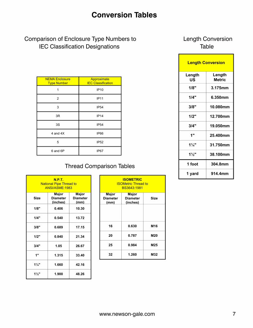
Comparison of Enclosure Type Numbers to
IEC Classification Designations
Length Conversion
Table
Thread Comparison Tables
NEMA EnclosureType Number
ApproximateIEC Classification
1
2
3
3R
3S
4 and 4X
5
6 and 6P
IP10
IP11
IP54
IP14
IP54
IP66
IP52
IP67
Length Conversion
LengthUS
1/8"
1/4"
3/8"
1/2"
3/4"
1"
1¼"
1½"
LengthMetric
3.175mm
6.350mm
10.080mm
12.700mm
19.050mm
25.400mm
31.750mm
38.100mm
1 foot
1 yard
304.8mm
914.4mm
N.P.T.National Pipe Thread to
ANSI/ASME:1983
SizeMajor
Diameter(inches)
Major Diameter
(mm)
1/8" 0.406 10.30
1/4" 0.540 13.72
3/8" 0.689 17.15
1/2" 0.840 21.34
3/4" 1.05 26.67
1" 1.315 33.40
1¼" 1.660 42.16
1½" 1.900 48.26
ISOMETRICISOMetric Thread to
BS3643:1981
SizeMajor
Diameter(inches)
Major Diameter
(mm)
0.63016
0.78720
0.98425
1.26032
M16
M20
M25
M32
Conversion Tables
AWG mm2
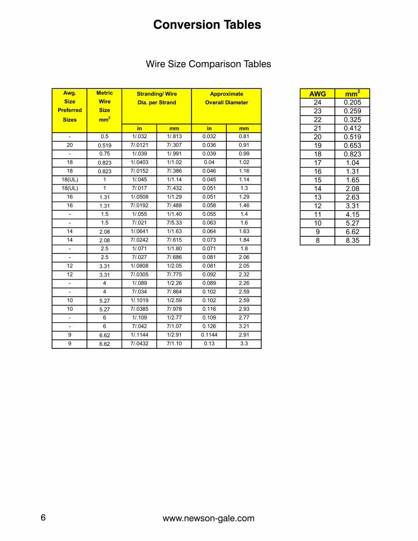
24 0.20523 0.25922 0.32521 0.41220 0.51919 0.65318 0.82317 1.0416 1.3115 1.6514 2.0813 2.6312 3.3111 4.1510 5.279 6.628 8.35
Awg. Metric
Size Wire
Preferred Size
Sizes mm2
in mm in mm
- 0.5 1/.032 1/.813 0.032 0.81
20 0.519 7/.0121 7/.307 0.036 0.91
- 0.75 1/.039 1/.991 0.039 0.99
18 0.823 1/.0403 1/1.02 0.04 1.02
18 0.823 7/.0152 7/.386 0.046 1.16
18(UL) 1 1/.045 1/1.14 0.045 1.14
18(UL) 1 7/.017 7/.432 0.051 1.3
16 1.31 1/.0508 1/1.29 0.051 1.29
16 1.31 7/.0192 7/.488 0.058 1.46
- 1.5 1/.055 1/1.40 0.055 1.4
- 1.5 7/.021 7/5.33 0.063 1.6
14 2.08 1/.0641 1/1.63 0.064 1.63
14 2.08 7/.0242 7/.615 0.073 1.84
- 2.5 1/.071 1/1.80 0.071 1.8
- 2.5 7/.027 7/.686 0.081 2.06
12 3.31 1/.0808 1/2.05 0.081 2.05
12 3.31 7/.0305 7/.775 0.092 2.32
- 4 1/.089 1/2.26 0.089 2.26
- 4 7/.034 7/.864 0.102 2.59
10 5.27 1/.1019 1/2.59 0.102 2.59
10 5.27 7/.0385 7/.978 0.116 2.93
- 6 1/.109 1/2.77 0.109 2.77
- 6 7/.042 7/1.07 0.126 3.21
9 6.62 1/.1144 1/2.91 0.1144 2.91
9 6.62 7/.0432 7/1.10 0.13 3.3
Approximate
Overall Diameter
Stranding/ Wire
Dia. per Strand
Wire Size Comparison Tables
Conversion Tables
www.newson-gale.com6 7www.newson-gale.com
Comparison of Enclosure Type Numbers to
IEC Classification Designations
Length Conversion
Table
Thread Comparison Tables
NEMA EnclosureType Number
ApproximateIEC Classification
1
2
3
3R
3S
4 and 4X
5
6 and 6P
IP10
IP11
IP54
IP14
IP54
IP66
IP52
IP67
Length Conversion
LengthUS
1/8"
1/4"
3/8"
1/2"
3/4"
1"
1¼"
1½"
LengthMetric
3.175mm
6.350mm
10.080mm
12.700mm
19.050mm
25.400mm
31.750mm
38.100mm
1 foot
1 yard
304.8mm
914.4mm
N.P.T.National Pipe Thread to
ANSI/ASME:1983
SizeMajor
Diameter(inches)
Major Diameter
(mm)
1/8" 0.406 10.30
1/4" 0.540 13.72
3/8" 0.689 17.15
1/2" 0.840 21.34
3/4" 1.05 26.67
1" 1.315 33.40
1¼" 1.660 42.16
1½" 1.900 48.26
ISOMETRICISOMetric Thread to
BS3643:1981
SizeMajor
Diameter(inches)
Major Diameter
(mm)
0.63016
0.78720
0.98425
1.26032
M16
M20
M25
M32
Conversion Tables
AWG mm2
24 0.20523 0.25922 0.32521 0.41220 0.51919 0.65318 0.82317 1.0416 1.3115 1.6514 2.0813 2.6312 3.3111 4.1510 5.279 6.628 8.35
Awg. Metric
Size Wire
Preferred Size
Sizes mm2
in mm in mm
- 0.5 1/.032 1/.813 0.032 0.81
20 0.519 7/.0121 7/.307 0.036 0.91
- 0.75 1/.039 1/.991 0.039 0.99
18 0.823 1/.0403 1/1.02 0.04 1.02
18 0.823 7/.0152 7/.386 0.046 1.16
18(UL) 1 1/.045 1/1.14 0.045 1.14
18(UL) 1 7/.017 7/.432 0.051 1.3
16 1.31 1/.0508 1/1.29 0.051 1.29
16 1.31 7/.0192 7/.488 0.058 1.46
- 1.5 1/.055 1/1.40 0.055 1.4
- 1.5 7/.021 7/5.33 0.063 1.6
14 2.08 1/.0641 1/1.63 0.064 1.63
14 2.08 7/.0242 7/.615 0.073 1.84
- 2.5 1/.071 1/1.80 0.071 1.8
- 2.5 7/.027 7/.686 0.081 2.06
12 3.31 1/.0808 1/2.05 0.081 2.05
12 3.31 7/.0305 7/.775 0.092 2.32
- 4 1/.089 1/2.26 0.089 2.26
- 4 7/.034 7/.864 0.102 2.59
10 5.27 1/.1019 1/2.59 0.102 2.59
10 5.27 7/.0385 7/.978 0.116 2.93
- 6 1/.109 1/2.77 0.109 2.77
- 6 7/.042 7/1.07 0.126 3.21
9 6.62 1/.1144 1/2.91 0.1144 2.91
9 6.62 7/.0432 7/1.10 0.13 3.3
Approximate
Overall Diameter
Stranding/ Wire
Dia. per Strand
Wire Size Comparison Tables
Conversion Tables
www.newson-gale.com6 7www.newson-gale.com

Universal Power SupplyEnclosure Mounting Dimensions
SIDE VIEW WITH LID IN PLACE
94
6.3
FRONT VIEW WITH LID IN PLACE
6.3
5.5
5.5
0.47" x 0.28" SLOT NOT TO SCALEDIMENSIONS IN INCHES
Front View with Lid Removed
CHASSIS PLATE
PCB
M20 Cable Entry fitted with IP65 Exe Blanking Plug. Installer to fit suitable gland or conduit adaptor when unit is externally powered.
Clamp Connector
Quick Connect
Crimp Connector
9 V Intrinsically Safe lithium manganese cell Ultralife U9VL-J battery or Varta 6122 E-Block (fitted for battery powered units only).
Bond-Rite REMOTE IIEnclosure Mounting Dimensions Including Wall-Mounted Brackets
Stainless Steel Version
FRONT VIEW WITH LID IN PLACE SIDE VIEW WITH LID IN PLACE
5.9
5.9
3.2
3.8
6.9
0.4
Stowage Pin for Grounding Clamp
1 x M20 gland entry for UPS version
Pulsing LED
NOT TO SCALEDIMENSIONS IN INCHES
NOT TO SCALEDIMENSIONS IN INCHES
Static Dissipative Glass Reinforced Polyester Version
6.3
SIDE VIEW WITH LID IN PLACE
3.7
FRONT VIEW WITH LID IN PLACE
6.3
5.5
5.5
0.47" x 0.28" SLOT
www.newson-gale.com8 9www.newson-gale.com

Bond-Rite REMOTE IICable Installation - Terminations
CLASSIFIED LOCATION
DIVISION 1 and 2CLASS I: A, B, C or DCLASS II: E, F or GCLASS III
IEC ZONE 0(20)
110/230V acSUPPLY
POWER SUPPLY UNIT
JUNCTIONBOX
VERIFIABLE STATIC
GROUND POINT
SITE STATIC GROUND BUS
BOND-RITE REMOTE II
UNITS
DIVISION 2, ZONE 2
NOTE: It is recommended that no more than 10 Bond-Rite REMOTE II units be powered from a single Universal Power Supply and that the maximum total cable length, between them, shall not exceed 500m
Bond-Rite REMOTE IICable Installation - Wiring
CLASSIFIED LOCATION
DIVISION 1 and 2CLASS I: A, B, C or DCLASS II: E, F or GCLASS III
IEC ZONE 0(20)
Cable from Junction Box to Bond-Rite REMOTE II Unit
Cable from Supply (Line) to the Power Supply Unit16AWG 2-conductor cable + Equipment Safety Ground (120/230V circuit).
Recommended Specification
Cable from Power Supply Unit to Junction Box16AWG 2-conductor cable with blue sheath or identifier (IS Circuit).
16AWG 2-conductor cable with blue sheath or identifier (IS Circuit).
Customer Supplied Cable Specification
www.newson-gale.com10 11www.newson-gale.com
M20CABLEENTRY
M20CABLEENTRY
M20CABLEENTRY VERIFIABLE STATIC
GROUND POINT
BOND-RITE REMOTE II
SITE STATIC GROUND BUS
DIVISION 2, ZONE 2
INTRINSICALLY SAFE OUTPUT
TERMINALS
CABLE ENTRIES VIA M20PLASTIC CABLE GLANDS
JUNCTIONBOX NEGATIVE
TERMINALS
POSITIVETERMINALS
POWERSUPPLY
UNIT
110 V acSUPPLY
230 V acSUPPLY
SUPPLYINPUT TERMINALS
THE CHASSIS OF THE POWERSUPPLY UNIT MUST BE
CONNECTED TO A PROTECTIVE EARTH POINT
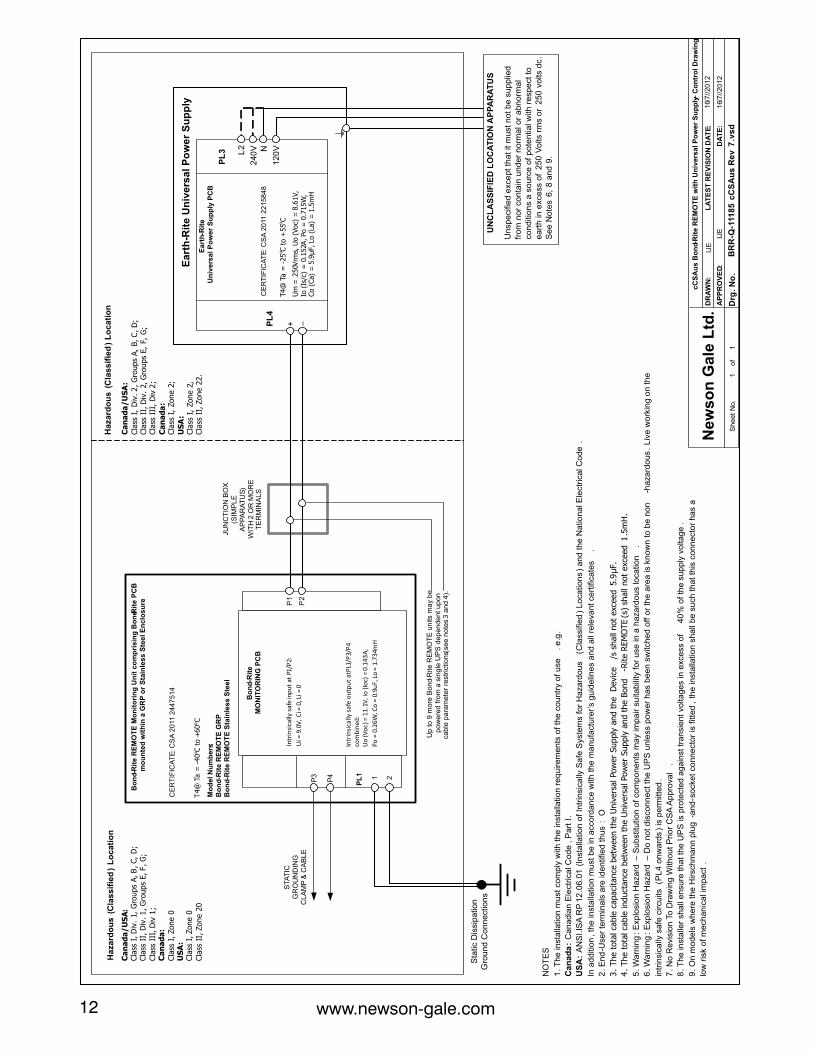
www.newson-gale.com12 13www.newson-gale.com
o oAmbient temperature range -25 C to +55 C
Canada/USA:
Intrinsically Safe Equipment Exia for use in:
Class I, Div. 1, Groups A, B, C, D
Class II, Div 1, Groups E, F, G
Class III, Div 1, when installed per
Control Dwg. BRR-Q-11185 cCSAus
o oT4@ Ta = -25 C to +55 C
Enclosure Type 4X, IP 66
CSA 2010 2215848
Canada:
Class I, Zone 2 (zone 0) AEx nA[ia] IIC T4
DIP A22 IP66 T70C
o oAmbient temperature range -40 C to +60 C
USA:
Class I, Zone 2 (zone 0) AEx nA[ia] IIC T4
Class II, Zone 22 AEx tD[iaD] 22 T70C
o oT4@ Ta = -40 C to +60 C
Enclosure Type 4X, IP 66
CSA 2011 2447514
Canada:
Ex ia IIC T4
DIP A20 IP66 T135C
Bond-Rite REMOTE II
USA:
AEx ia IIC T4:
AEx iaD 20 T135C
Associated apparatus for in:
Class I, Div. 2, Groups A, B, C, D
Class II, Div 2, Groups E, F, G
Class III, Div 2, providing Intrinsically Safe circuits for
Class I, Div. 1, Groups A, B, C, D
Class II, Div 1, Groups E, F, G
Class III, Div 1, when installed per
Control Dwg. ERUPS-Q-09212
Universal Power Supply
Bond-Rite REMOTE IIApproval Details
P1
P2
DR
AW
N:
LA
TE
ST
RE
VIS
ION
DA
TE:
AP
PR
OV
ED
:
DA
TE
:N
ew
so
n G
ale
Ltd
.
Drg
. N
o.
BR
R-Q
-111
85
cC
SA
us
Re
v 7
.vs
dS
he
et
No.
1
IJE
IJE
of
1
16/
7//2
01
2
cC
SA
us
Bo
nd-
Rit
e R
EM
OT
E w
ith
Un
ive
rsa
l P
ow
er
Su
pp
ly –C
on
tro
l D
raw
ing
Ea
rth
-Rit
e U
niv
ers
al
Po
we
r S
up
ply
24
0V
12
0V
NO
TE
S
1. T
he
inst
alla
tion
mu
st c
om
ply
with
th
e in
sta
llatio
n r
eq
uire
me
nts
of
the
co
un
try
of
use
. e
.g.
Ca
na
da
:C
an
ad
ian
Ele
ctrica
l Co
de
, P
art
I.
US
A:
AN
SI.
ISA
RP
12
.06.0
1 (
Inst
alla
tion
of
Intr
insi
ca
lly S
afe
Sys
tem
s fo
r H
aza
rdo
us
(Cla
ssifi
ed
) L
oca
tion
s)
an
d t
he
Na
tion
al E
lect
rica
l Co
de
.
In a
dd
itio
n, th
e in
sta
llatio
n m
ust
be
in a
cco
rda
nce
with
th
e m
an
ufa
ctu
rer’
s g
uid
elin
es
an
d a
ll re
leva
nt
cert
ifica
tes
.
2. E
nd
-Use
r te
rmin
als
are
ide
ntif
ied
th
us
: O
3. The t
ota
l ca
ble
capaci
tance
betw
een t
he U
niv
ers
al Pow
er
Supply
and t
he D
evi
ce/s
shall
not
exc
eed 5
.9µF.
4. The t
ota
l ca
ble
induct
ance
betw
een t
he U
niv
ers
al Pow
er
Supply
and t
he B
ond
-Rite R
EM
OTE
(s)
shall
not
exc
eed 1
.5m
H.
5. W
arn
ing
: E
xplo
sio
n H
aza
rd –
Su
bst
itutio
n o
f co
mp
on
en
ts m
ay
imp
air s
uita
bili
ty f
or
use
in a
ha
zard
ou
s lo
catio
n.
6. W
arn
ing
: E
xplo
sio
n H
aza
rd –
Do
no
t d
isco
nn
ect
th
e U
PS
un
less
po
we
r h
as
be
en
sw
itch
ed
off o
r th
e a
rea
is k
no
wn
to
be
no
n-h
aza
rdo
us
. L
ive
wo
rkin
g o
n t
he
intr
insi
cally
sa
fe c
ircu
its (P
L4
on
wa
rds
) is
pe
rmitt
ed
.
7.N
o R
evi
sio
n T
o D
raw
ing
With
ou
t P
rio
r C
SA
Ap
pro
va
l.
8. T
he
inst
alle
r sh
all
en
sure
th
at
the
UP
S is
pro
tect
ed
ag
ain
st t
ran
sie
nt
volta
ge
s in
exc
ess
of
40
% o
f th
e s
up
ply
vo
ltag
e.
9. O
n m
od
els
wh
ere
th
e H
irsc
hm
an
n p
lug
-an
d-s
ocke
t co
nn
ecto
r is
fitt
ed
, th
e in
sta
llatio
n s
ha
ll b
e s
uch
th
at
this
co
nn
ect
or
ha
s a
low
ris
k o
f m
ech
an
ica
l im
pa
ct.
NL2
_
PL
3
Ea
rth-R
ite
Un
ive
rsa
l P
ow
er
Su
pp
ly P
CB
Canada/USA:
Cla
ss I
, D
iv. 2, G
roups
A,
B, C
, D
;Cla
ss I
I, D
iv.
2, G
roups
E,
F,
G;
Cla
ss I
II,
Div
2;
Canada:
Cla
ss I
, Zone 2
;
USA:
Cla
ss I
, Zone 2
,Cla
ss I
I, Z
one 2
2.
Canada/USA:
Cla
ss I
, D
iv.
1,
Gro
ups
A, B
, C,
D;
Cla
ss I
I, D
iv. 1, G
roups
E, F, G
;
Cla
ss I
II, D
iv 1
;Canada:
Cla
ss I
, Zone 0
USA:
Cla
ss I
, Zone 0
Cla
ss I
I, Z
one 2
0
Ha
zard
ou
s (
Cla
ss
ifie
d)
Lo
ca
tio
nH
aza
rdo
us
(C
las
sif
ied
) L
oc
ati
on
T4@
Ta =
-25
o C t
o +
55o
C
Um
= 2
50V
rms,
Uo (Voc)
= 8
.61V,
Io (
Is/c
) =
0.1
52A
, Po =
0.7
15W
, Co (
Ca)
= 5
.9µF, Lo
(La
) =
1.5
mH
+PL
4
Un
spe
cifie
d e
xce
pt
tha
t it m
ust
no
t b
e s
up
plie
d
fro
m n
or
con
tain
un
de
r n
orm
al o
r a
bn
orm
al
con
ditio
ns
a s
ou
rce
of
po
ten
tia
l w
ith
re
spe
ct t
o
ea
rth
in
exc
ess
of
25
0 V
olts
rms
or
25
0 v
olts
dc
.S
ee
No
tes
6,
8 a
nd
9.
UN
CL
AS
SIF
IED
LO
CA
TIO
N A
PP
AR
AT
US
JUN
CT
ION
BO
X(S
IMP
LE
A
PP
AR
AT
US
)W
ITH
2 O
R M
OR
E
TE
RM
INA
LS
CE
RT
IFIC
AT
E: C
SA
20
11 2
21
58
48
PL
1 2
Sta
tic D
issi
pa
tion
G
rou
nd
Co
nn
ect
ion
s
Intr
insi
cally
saf
e o
utp
ut
at P
L1/P
3/P
4
com
bin
ed:
Uo
(Vo
c) =
11.
1V,I
o (I
oc)
= 0
.14
3A
,
Po =
0.2
6W,C
o =
0.9
uF,
Lo =
1.7
34m
H1P4
P3
Bo
nd-R
ite
RE
MO
TE
Mo
nit
ori
ng
Un
it c
om
pri
sin
g B
on
d-Rit
e P
CB
m
ou
nte
d w
ith
in a
GR
P o
r S
tain
les
s S
tee
l E
nc
los
ure
T4@
Ta =
-40o
C t
o +
60
oC
Bo
nd-R
ite
M
ON
ITO
RIN
G P
CB
Mo
de
l N
um
be
rs:
Bo
nd-R
ite
RE
MO
TE
GR
PB
on
d-R
ite
RE
MO
TE
Sta
inle
ss
Ste
el
CE
RT
IFIC
AT
E: C
SA
20
11 2
44
75
14
Intr
insi
cally
saf
e in
pu
t at
P1/
P2:
Ui=
9.0
V,
Ci =
0, L
i = 0
STA
TIC
G
RO
UN
DIN
G
CL
AM
P &
CA
BL
E
Up
to
9 m
ore
Bo
nd-
Rite
RE
MO
TE
un
its m
ay
be
p
ow
ere
d f
rom
a s
ing
le U
PS
de
pe
nd
en
t u
po
n
cab
le p
ara
me
ter
rest
rict
ion
s (se
e n
ote
s 3
an
d 4
).
16/
7//2
01
2

www.newson-gale.com14 15www.newson-gale.com

www.newson-gale.com14 15www.newson-gale.com

www.newson-gale.com NG
US
BR
RE
MO
TE
II IS
M 0
30
61
9 R
10
United Kingdom
Private Road 8
+44 (0)115 940 7500
Colwick, Nottingham
NG4 2JX, UK
Newson Gale Ltd
Omega House Kaiserswerther Str. 85C
Germany
40878 Ratingen
IEP Technologies GmbH
+49 (0)2102 5889 0
Deutschland
[email protected] East Asia
United States
IEP Technologies LLC
USA
Marlborough, MA 01752
417-1 South Street
+1 732 961 7610