bond strength of galvanized steel: experimental and
TRANSCRIPT
Bond strength of galvanized steel: experimental and numerical study based on pull-out tests
Luna Molina, Francisco Javier1; Fernández Ruiz, Manuel Alejandro2; Hernández Montes, Enrique3;
Alonso Alonso, María Cruz4
ABSTRACT
The construction of more durable structures is becoming a mandatory requirement. Different alternatives are followed in reinforced concrete structures, as the use of galvanized reinforcement to increase the service life. Due to the fact that the interaction between concrete and galvanized steel is different from the carbon steel case, the bond strength might call into question. The present article studies the bond stress development of conventional and hot-dip galvanized steel reinforcement embedded in concrete made with Ordinary Portland Cement (OPC). Results indicate that maximum bond stress measured for galvanized steel is similar to that of conventional reinforcement. Furthermore, the numerical model developed with ABAQUS notably reproduces the contact between concrete and galvanized steel with the help of the experimental pull out tests carried out, showing a practical implementation for future structural element analysis.
Keywords: Bond strength, galvanized steel, pull-out, numerical model.
1. INTRODUCTION
Reinforced concrete is nowadays one of the most widely used construction material all over the world. It has a lot of advantages (inexpensive, it can be cast to take the shape required, relatively high compressive strength, etc.), but it has a great weakness: the potential for the steel reinforcement to corrode (especially in certain exposure conditions). This is a big problem because it provokes a reduction of the area of steel and the cracking and failure of the surrounding concrete, reducing the service life of the structure (and consequently increasing the costs of maintenance and rehabilitation). A solution can be the following: the use of galvanized steel as reinforcement in RC structures [1].
The hot-dip galvanized steel, that is the most used galvanizing method, has an impervious metallic zinc barrier around the bar that isolates it from the surrounding concrete. This galvanized coating, among other improvements, increases the chloride concentration threshold for corrosion, besides
1 Construction Department. Eduardo Torroja Institute for Construction Sciences (SPAIN). [email protected] (Corresponding author)
2 Structural Mechanics Department. University of Granada (SPAIN). [email protected]
3 Structural Mechanics Department. University of Granada (SPAIN). [email protected]
4 Construction Department. Eduardo Torroja Institute for Construction Sciences (SPAIN). [email protected]
143

Bond strength of galvanized steel: experimental and numerical study based on pull-out tests Third International Conference on Mechanical Models in Structural Engineering University of Seville. 24
th-26
th June 2015.
that the corrosion rate of this layer is lower than in bare steel [2]. It is obvious that the inclusion of this galvanized coating is a good solution to prevent the corrosion, but also it is true that it affects the steel-concrete bond in some way.
In a reinforced concrete structure, it is essential to guarantee a perfect functionality of concrete and reinforcement, being the bond between them a critical point. This interaction has been studied over the past few decades theoretically and experimentally in the literature [3-4], but it continues having some uncertainties and unknowns to resolve.
The comparison of published results is not an easy task because the materials and testing conditions differ from each other. For example, not all research has been performed in concrete, also using bars embedded in cement pastes or mortars [5, 6] and not always ribbed reinforcement were employed [7]. In addition to this, the conditions of the pull-out tests vary [8-9] and beam tests are also employed [10], increasing the heterogeneity of the experimental campaigns carried out in the literature. Besides that, lots of factors affect the bond strength between concrete and reinforcement as can be w/c ratio, compression and tensile strength of concrete, type of aggregate and its maximum size, rebar composition and surface geometry, rebar superficial state (rust, coating, etc.), rebar diameter, or even the position of the rebar in the block of concrete and bond length, without forgetting the different mechanical test used for bond strength determination. The importance of the rebar surface geometry and the superficial state of the rebar [1, 11] explains the importance of carrying out a specific research when galvanized steel is used as reinforcement, especially due to the lack of studies related with this theme (and in some cases obtaining contradictory results) [1, 12].
Nowadays finite element analysis is widely used for modeling the behavior of reinforced concrete structures. Among the components that constitute these structures there are steel bars in contact with concrete, being a crucial part of the structural behavior the correct simulation of the bond between them. It is not always a good idea to model the rebar embedded in the concrete (assuming that both have the same strain in points initially in contact). In some cases (high stresses in the reinforcement) the best option is to model the bond behavior with the help of a pull out test (experimental or analytical), where the strain of the bar is different than the strain of the concrete in points initially in contact.
In this study, a method to model numerically in ABAQUS [13] the bond behavior between steel and concrete based on experimental results of pull-out tests is developed in order to take it into account when a reinforced concrete member is analyzed.
The development process of a numerical model is not a simple task, and it is even more laborious if the complexity of the problem increases (contact interaction, material and geometrical non-linearity, etc.). In Henriques et al. [14] a numerical study to simulate composite beam to reinforced concrete wall joints using the finite element software ABAQUS [13] is defined. They use a traction-separation law to model the bond behavior of steel bars and concrete, using the formulation presented in Gan [15] and obtaining respectable results. Here, the same formulation is used in order to simulate the experimental tests in ABAQUS [13] and to be able to model a reinforced concrete member with this contact interaction verified experimentally.
144

Luna Molina, F.J.1, Fernández Ruiz, M.A.
2, Hernández Montes, E.
3 and Alonso Alonso, M.C.
4
2. EXPERIMENTAL WORK
2.1. Tests
For the determination of the bond strength, pull-out tests have been carried out following the prescriptions proposed in [16]. The specimens consist in a 200x200x200 mm concrete cube with a rebar of 16 mm of diameter embedded in its center. The contact between the bar and the concrete is
located along a length of 5ɸ (80 mm) and the rebar is covered by a plastic tube in the remaining length inside the concrete (120 mm), impeding the contact between them. The bar must have enough length in both extremes to apply the tensile load in the one and to record the slip in the other. The tensile load is applied at 300 mm from the cube in the longest extreme of the rebar and the measure of the slip is taken 50 mm from the cube in the free extreme according with [16]. The rebar is tensioned by a 160 kN hydraulic jack that reacts to a 110 kN load cell and an iron plate resting in the concrete cube. The tensile load increases at a constant rate, in this case 0,14 kN/s, that depends on the rebar diameter according to the formulation proposed in [16] (see Eq. [1]).
= (1)
Where d is the rebar diameter.
In the free extreme, three 10 mm linear voltage displacement transducers (LVDT’s) are placed around the rebar at 50 mm from the cube in order to measure the displacement with a precision of 0,005 mm. The tensile load and the displacement are recorder during the test for their posterior treatment. A general view of the used equipment can be observed in Figure 1.
To convert the value of the tensile force applied in the rebar (Fa) into bond stress (τdm), the formulation proposed in [16] is used (see Eq.(2)).
=
(1)
Where fcm and fc are the mean and the characteristic compressive strength of the concrete
respectively and ɸ is the rebar diameter.
Two campaigns of tests have been carried out. In each campaign, for the pull-out tests, two specimens have been made for each steel-concrete configuration and for each age (7 and 28 days). For the mechanical characterization of the concrete were made two 100x200 mm cylindrical specimens for each type of test. In summary, the number of specimens for each test is described with more detail in Table 1.
The employed steel was the standardized B500SD of 16 mm diameter, all from the same supplier. Half of steel rebars were submitted to a hot-dip galvanizing process through its immersion in a hot bath of Zinc (99% purity) at 450 ºC during approximately 1 minute followed by a cooling process at the atmosphere. The galvanized coating presented transversal continuity (shown in Figure 2) and it is constituted by several sub layers with different proportions of Fe/Zn alloyed sub layers plus an external pure zinc layer as described in [1]. As it can be observed in Table2, which shows the mean values of 3 rebars for each steel, the galvanizing process has not affected the mechanical properties of the rebars.
145

Bond strength of galvanized steel: experimental and numerical study based on pull-out tests Third International Conference on Mechanical Models in Structural Engineering University of Seville. 24
th-26
th June 2015.
Table 1. Number of specimens for each test
Test Age (days)
7 28
Pull-out test
Carbon steel rebars 4 4 Galvanized steel rebars 4 4
Compression test 4 4 Tensile test 4 4
Figure 1. General view of the bond test arrangement
Figure 2. Detail of hot-dip galvanized steel rebars coating
146

Luna Molina, F.J.1, Fernández Ruiz, M.A.
2, Hernández Montes, E.
3 and Alonso Alonso, M.C.
4
Table 2. Mechanical properties of the rebars
Steel Elastic limit (MPa) Yield strength
(MPa)
Non galvanized 550,00 ± 7,00 657,63 ± 4,15 Hot-dip galvanized 554,63 ± 3,56 663,60 ± 0,69
The employed concrete contains 842 kg of 6/12 mm aggregates, 802 kg of sand and 385 kg of cement per cubic meter, presenting a water/cement ratio of 0,6. In Table 3 the mechanical characteristic of the concrete are shown.
Table 3. Compressive and tensile strength of concrete (MPa)
Compressive strength Tensile strength
7 days 28 days 7 days 28 days
17.6 ± 2.0 27.3 ± 0.3 2.45 ± 0.00 2.80 ± 0.25
All specimens were cured in a chamber at 20 ºC and 95% relative humidity until the age of testing according to EN 12390-2:2009 [17].
2.2. Experimental results
The experimental results of the bond tests for the two campaigns are presented in Figures 3-7:
Figure 3. Bond stress development at 7 days – Campaign 1
0
5
10
15
0 5 10 15
7 d
ays
bo
nd
str
en
gth
(N
/mm
2)
Slip (mm)
CS-S1
CS-S2
GS-S1
147

Bond strength of galvanized steel: experimental and numerical study based on pull-out tests Third International Conference on Mechanical Models in Structural Engineering University of Seville. 24
th-26
th June 2015.
Figure 4. Bond stress development at 7 days – Campaign 2
Figure 5. Bond stress development at 28 days – Campaign 1
0
5
10
15
0 5 10 15
7 d
ays
bo
nd
str
en
gth
(N
/mm
2)
Slip (mm)
CS-S1
CS-S2
GS-S1
GS-S2
0
5
10
15
0 5 10 15
28
day
s b
on
d s
tre
ngt
h (
N/m
m2)
Slip (mm)
CS-S1
GS-S1
GS-S2
148

Luna Molina, F.J.1, Fernández Ruiz, M.A.
2, Hernández Montes, E.
3 and Alonso Alonso, M.C.
4
Figure 6. Bond stress development at 28 days – Campaign 2
Where CS: carbon steel rebar and GS: hot-dip galvanized steel rebar.
Hot-dip galvanized steel rebars present a smaller value of the maximum bond strength at 7 days than the one of the carbon steel rebars and a similar value for 28 days (Table 4). The result obtained at 28 days shows that the new superficial geometry due to the galvanized coating does not affect in a negative way the ultimate bond strength. Besides that the interaction with concrete in the interface between it and the galvanized steel just slightly decrease the strength at early ages (Table 3), becoming sometimes harmless (Figure 4). The results at 7 days are in agreement with the reported in [2, 12] but Sena et al. [12] showed that galvanized rebars also develop lower bond stress at the age of 28 days. The reason may be attributed to the fact that in Sena et al. the specimens had a longer length of the rebar than in the present work and therefore the influence of the interaction concrete/zinc could affect in a negative way for a longer period.
The slip associated to the ultimate bond strength (see Table 4) also provides information that must be taken into account in order to define with a higher accuracy the bond behavior. Not only that, the numerical model shown later considers the yield point as an essential parameter to analyze the structural element.
As it can be observed, galvanized steel rebars develop a slightly higher ultimate bond stress with concrete at the age of 28 days, however it is notable to point out that the bond failure happens for a lower displacement than the non-galvanized ones. Regarding to early ages, there are no differences in the slip at the yield point.
0
5
10
15
0 5 10 15
28
day
s b
on
d s
tre
ngt
h (
N/m
m2)
Slip (mm)
CS-S1 CS-S2 GS-S1 GS-S2
149

Bond strength of galvanized steel: experimental and numerical study based on pull-out tests Third International Conference on Mechanical Models in Structural Engineering University of Seville. 24
th-26
th June 2015.
Table 4. Ultimate bond stress with concrete and associated slip for both types of steel reinforcement
Age (days)
Campaign
Carbon steel Galvanized steel
Ultimate bond stress (MPa)
Slip at ultimate bond stress (mm)
Ultimate bond stress (MPa)
Slip at ultimate bond stress (mm)
7
Campaign 1 8.66 ± 0.77 2.19 ± 0.09 6.82 ± n/c 1.72 ± n/c
Campaign 2 8.70 ± 0.68 2.65 ± 0.22 8.80 ± 0.37 3.02 ± 0.74
Average 8.68 ± 0.02 2.42 ± 0.23 7.81 ± 0.99 2.37 ± 0.65
28
Campaign 1 9.73 ± n/c 2.58 ± n/c 10.24 ± 0.30 2.22 ± 0.11
Campaign 2 10.00 ± 0.73 2.39 ± 0.001 9.82 ± 0.29 1.87 ± 0.43
Average 10.00 ± 0.73 2.39 ± 0.001 9.82 ± 0.29 1.87 ± 0.43
3. NUMERICAL SIMULATION
3.1. Description of the general finite element model
In this study the numerical tool used to model the pull-out test described in the experimental work is the non-linear finite element program ABAQUS (v6.13.1). This software is very extended within the academic field because it provides a flexible and complete solution for a large range of problems. The full description of the characteristics and techniques that includes ABAQUS is outside the scope of this study, for more detailed information about the software see [13].
A three-dimensional ABAQUS/Standard finite element model has been done. The whole model is comprised of deformable, eight-node with reduced integration (to avoid shear locking) hexahedral elements (C3D8R), elements selected after a sensitivity analysis in order to check the type and the mesh density.
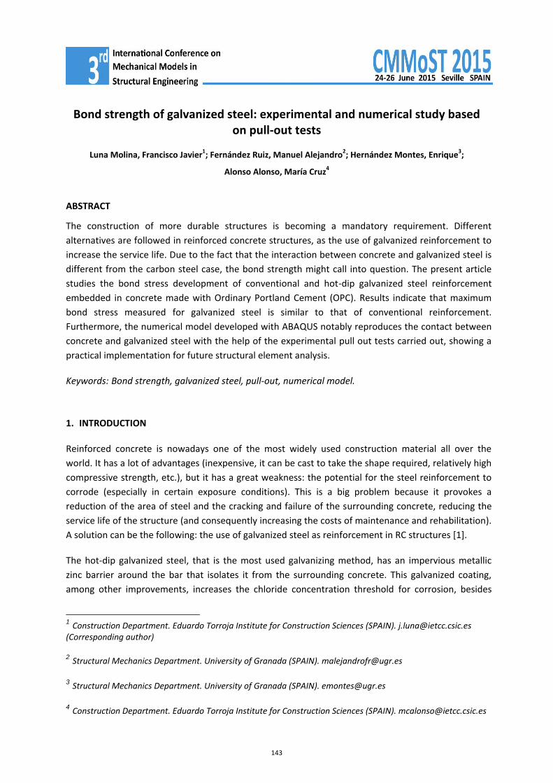
The model is constituted of two components: the concrete block and the steel bar. The concrete block is a 20x20x20 cm cube with a cylindrical hole through its center, hole that has exactly the same diameter than the rebar in the part where there is contact between the steel bar and concrete and has a diameter 2 mm greater than the rebar in the part in where there is contact between concrete and the reinforcement bar surrounded of plastic (see Figure 7). This separation ensures that there is not any kind of contact between the bar and the concrete in this region, locating all the material interaction just in the prescribed bond length, the final 8 cm. As it is explained in the experimental work, the concrete block is supported by a table which is immobile, so the bottom face of the concrete block is considered clamped (no translations and rotations at all). Owing to the fact that the hydraulic jack is supported by the top face of the concrete block, a uniform pressure σ equal to the traction force divided by the top area (subtracting the hole of the rebar) is applied. Regarding the bar, a cylinder of 65 cm and 16 mm of diameter is generated and it is placed into the hole of the concrete
150
Luna Molina, F.J.1, Fernández Ruiz, M.A.
2, Hernández Montes, E.
3 and Alonso Alonso, M.C.
4
block so that there is enough length in its extremes in order to apply the load and to measure the displacement. The external action is introduced in the model by means of a fixed displacement δ in the bottom surface of the rebar. All the boundary conditions explained above are sketched in figure 7.
Figure 7. Sketch of the restrictions and geometry of the concrete block in the finite element model.
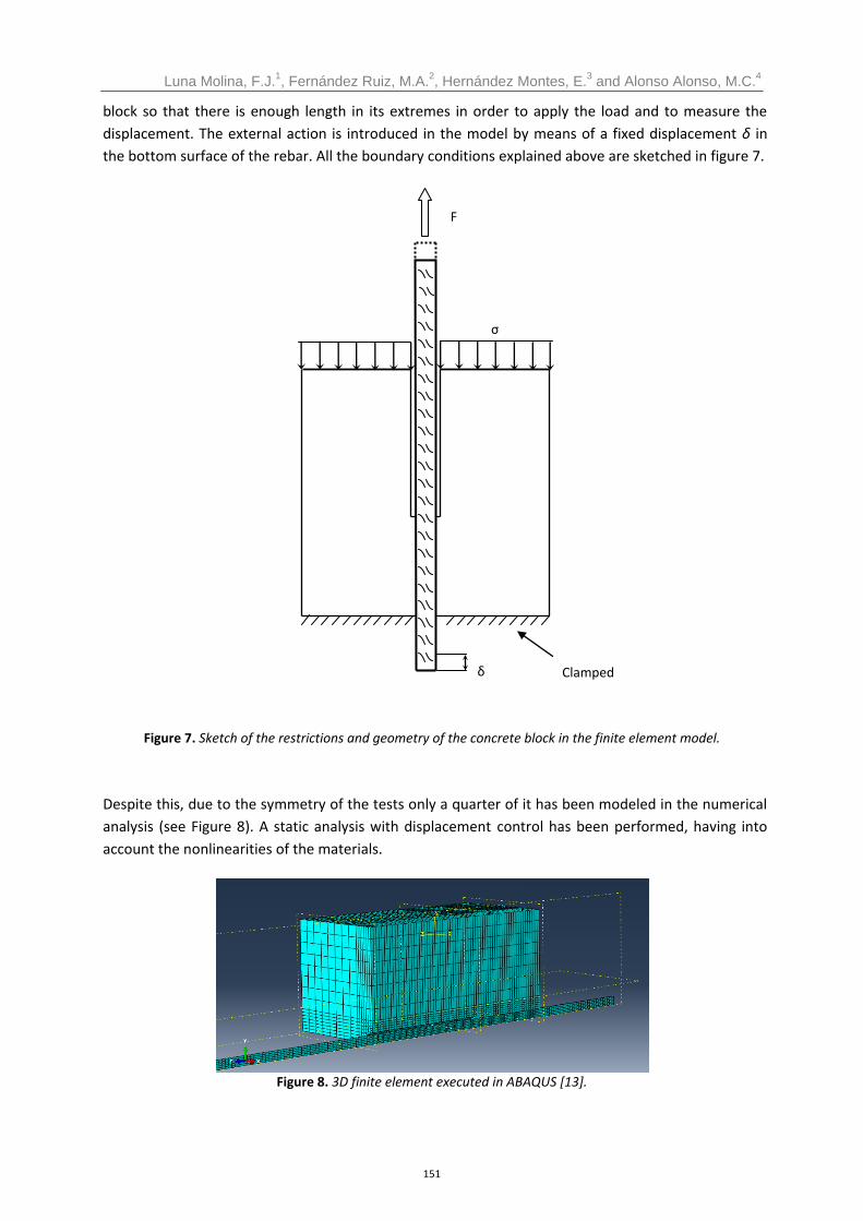
Despite this, due to the symmetry of the tests only a quarter of it has been modeled in the numerical analysis (see Figure 8). A static analysis with displacement control has been performed, having into account the nonlinearities of the materials.
Figure 8. 3D finite element executed in ABAQUS [13].
Clamped
σ
F
δ
151

Bond strength of galvanized steel: experimental and numerical study based on pull-out tests Third International Conference on Mechanical Models in Structural Engineering University of Seville. 24
th-26
th June 2015.
3.2. Constitutive laws and materials properties
ABAQUS [13] has a quite large material library and, depending of the type of analysis, some models of the same material are more suitable than others. After the analysis of the different concrete materials, the Concrete Damaged Plasticity was chosen because it is more stable for the numeric calculation and its modeling is simpler. This model consists of the combination of nonassociated multi-hardening plasticity and scalar (isotropic) damaged elasticity in order to describe the irreversible damage that occurs during the fracturing process. To define the Concrete Damaged Plasticity model it is necessary to specify the uniaxial tension and compression response of concrete and 5 parameters: ψ the dilation angle, ε the flow potential eccentricity, fb0/fc0 the ratio of initial equibiaxial compressive yield stress to initial compressive yield stress, k the ratio of second stress invariant on the tensile meridian and μ the viscosity parameter. There is not information about these parameters from the experimental test, so default values presented in Table 5 are assumed [13].
Table 5. Default parameters to define Concrete Damaged Plasticity constitutive model
ψ ε fb0/fc0 k μ
38 0.1 1.16 0.667 0.667
For the mechanical characterization of the concrete only the usual parameters of the compression and tension strength are reported and then the entire stress-strain curve is not available so a non-linear stress-strain relation for compression and tension proposed by Eurocode 2 [18] has been assumed (Figure 9).
Figure 9. Concrete uniaxial stress-strain law in compression and tension proposed by Eurocode 2 [18].
In tension, the behavior of concrete is assumed linear (elastic) up to the onset of cracking (until fctm is reached), where tension decreases to 0 almost immediately (there is not tension-stiffening, the contact between steel and concrete is going to be modeled with cohesive behavior).
fcm
εc1 εcu1 εc εt
0.4 fcm
Ecm
fctm
σc
σt
152

Luna Molina, F.J.1, Fernández Ruiz, M.A.
2, Hernández Montes, E.
3 and Alonso Alonso, M.C.
4
The model of the behavior of the steel is an elasto plastic with hardening stress-strain law. To represent the initial behavior, a linear law is defined with the elastic mechanical properties of the steel (Es and ν, the elastic modulus and the Poisson coefficient respectively). For the following part of the model, the stress-strain material curve available from the experimental tests is considered.
3.3. Steel bar – concrete block contact interaction
In this case, the importance of the model of the bar forces to build it with 3D solid elements. Selected this option, the interaction between these two materials can be embedded or specifying the bond behavior.
The embedded option corresponds to a perfect bond behavior that implies the rigid connection between the bar and the concrete nodes (physically the two parts are superposed). This technique is based on master and slave regions, where the nodes of the embedded region (the steel bar, slave) has the same strain as the closest node of the host region (the concrete block, master), obtaining a perfect bond between the master and the slave regions. This option is easier to define and is the best choice in regions where the stress transfer is medium, but in regions with high stresses (for instance near cracks) it is not suitable. In these regions, the reinforcement has a different strain than the concrete (the loss of bond produces a slip between the materials), so if the embedded option is used in this case an excessive stress in concrete and stiffer response of the reinforcement are going to be obtained.
The other choice is to model the interaction concrete-steel with a bond-slip law. The main difference with the embedded technique is that the steel bar and the concrete block are not superposed and each one can have different strain, which is suitable in high-stressed regions as it is said above. The disadvantage is that is more difficult to define and its implementation is more time consuming. Again, two options to model the bond behavior in the steel-concrete interface are available: cohesive elements and contact with cohesive behavior. The use of surface-based cohesive behavior is easier than the cohesive elements, and both provide the same results in general and common contacts. In more complex interactions the best choice is the cohesive element, but in this case the surface-based behavior is chosen due to the simplicity of the contact interaction.
To sum up, the contact interaction between the concrete block and the steel bar is model with a surface-based cohesive behavior where the interpenetration between both surfaces is prevented by contact.
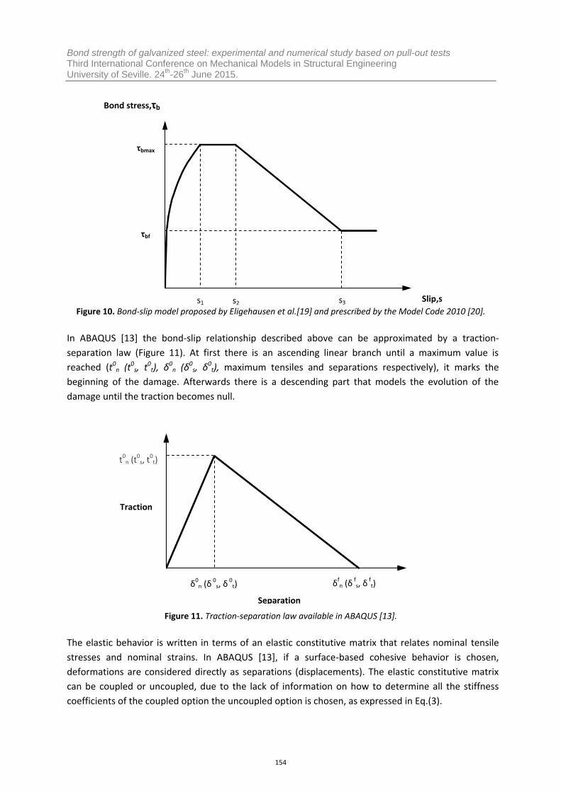
The stress-slip relation proposed by Eligehausen et al.[19] is considered the theoretical basis for the modeling of the reinforcement-concrete interaction and it is prescribed by the Model Code 2010 [20]. Figure 10 shows the bond-slip model proposed by Eligehausen et al.[19], where the initial penetration of the ribs into the mortar matrix is represented with the ascending part, up to a maximum stress (τbmax), followed by a plateau only for confined concrete. Finally, the descending part refers to the reduction of bond resistance as concrete corbels between the ribs are sheared off before a constant residual level is reached (ultimate frictional bond resistance, τbf).
153
Bond strength of galvanized steel: experimental and numerical study based on pull-out tests Third International Conference on Mechanical Models in Structural Engineering University of Seville. 24
th-26
th June 2015.
Figure 10. Bond-slip model proposed by Eligehausen et al.[19] and prescribed by the Model Code 2010 [20].
In ABAQUS [13] the bond-slip relationship described above can be approximated by a traction-separation law (Figure 11). At first there is an ascending linear branch until a maximum value is reached (t0
n (t0s, t0
t), δ0n (δ0
s, δ0t), maximum tensiles and separations respectively), it marks the
beginning of the damage. Afterwards there is a descending part that models the evolution of the damage until the traction becomes null.
Figure 11. Traction-separation law available in ABAQUS [13].
The elastic behavior is written in terms of an elastic constitutive matrix that relates nominal tensile stresses and nominal strains. In ABAQUS [13], if a surface-based cohesive behavior is chosen, deformations are considered directly as separations (displacements). The elastic constitutive matrix can be coupled or uncoupled, due to the lack of information on how to determine all the stiffness coefficients of the coupled option the uncoupled option is chosen, as expressed in Eq.(3).
Separation
Traction
t0n (t0
s, t0
t)
δ0n (δ 0
s, δ 0
t) δfn (δ f
s, δ f
t)
Bond stress,τb
τbmax
τbf
s1 s2 s3 Slip,s
154

Luna Molina, F.J.1, Fernández Ruiz, M.A.
2, Hernández Montes, E.
3 and Alonso Alonso, M.C.
4
(3)
In Eq.(3) T is the nominal traction stress vector that consists of three components: tn, ts and tt, which represent the normal and the two shear tractions respectively. Similarly, the separation vector is composed by the three components δn, δs, δt, which are respectively the displacements related with the normal and transversal directions. Finally Knn, Kss and Ktt are the stiffness coefficients.
According to [14] and [15] Kss and Ktt are obtained by approximation of the bond-slip relation showed in Figure 10 as expressed in Eq.(4) and the stiffness of the normal traction is higher than in the shear direction as expressed in Eq.(5).
(4)
(5)
In accordance with the above-mentioned, the true bond-slip laws are available and the values of Kss and Ktt (and consequently Knn) are exactly calculated (τmax is the maximum shear stress and s1 is the displacement when τmax is reached), see Figure 12. To define the damage initiation (that marks the beginning of degradation of the cohesive response at a contact point) a maximum separation criterion is assumed. Afterwards the damage evolution is defined, that describes the rate at which the cohesive stiffness is degraded once the corresponding initiation criterion is reached. A decreasing linear evolution based on the energy that is dissipated as a result of the damage process (also called the fracture energy) is used. The fracture energy is equal to the area under the traction-separation curve, and its value is the same as the area under the true bond-slip relation obtained in the tests (see Figure 12).
Figure 12. Approximation of the real bond-slip relation (grey line) with a traction-separation law (black line). Both have the same area under each curve.
τ
s s1
τmax
155

Bond strength of galvanized steel: experimental and numerical study based on pull-out tests Third International Conference on Mechanical Models in Structural Engineering University of Seville. 24
th-26
th June 2015.
3.4. Numerical results
Now with the help of the experimental results, the behavior of the bond between steel and concrete is simulated in ABAQUS [13] in order to check the accuracy of the software to compute this kind of contact. Known the maximum shear stress and the slip when it is reached in each test of each campaign, a mean value can be calculated. With these mean values, the linear traction-separation laws for both types of steel can be introduced in ABAQUS [13], obtaining the results shown in Figure 13 and Figure 14 for carbon steel and galvanized steel respectively.
Figure 13. Numerical simulation of the experimental campaigns using carbon steel reinforcement and reference concrete at 28 days.
Figure 14. Numerical simulation of the experimental campaigns using galvanized steel reinforcement and reference concrete at 28 days.
As it can be seen in Figure 13 and Figure 14, ABAQUS [13] can simulate the contact between different types of steel (carbon and galvanized steel) with an adequate level of accuracy.
0
2
4
6
8
10
12
0 5 10 15 20
Bo
nd
str
en
gth
(N
/mm
2)
Slip (mm)
Campaign 1 Campaign 2 Abaqus
0
2
4
6
8
10
12
0 5 10 15 20
Bo
nd
str
en
gth
(N
/mm
2)
Slip (mm)
Campaign 1 Campaign 2 Abaqus
156

Luna Molina, F.J.1, Fernández Ruiz, M.A.
2, Hernández Montes, E.
3 and Alonso Alonso, M.C.
4
4. CONCLUSIONS
The pull-out test done have shown that galvanized steel rebars develop the same ultimate bond strength at 7 days than conventional ones do and that the use of hot-dip galvanized steels rebars slightly modify the bond behavior of a conventional steel reinforcement with concrete at the age of 28 days. It can be said that if galvanized steel is used, the value of the maximum bond strength is a bit higher than the obtained for the carbon steel and it is developed for a displacement a bit smaller (more tests and studies are needed to ensure this affirmation). The main conclusion according the obtained results is that galvanized steel bars are as valid as conventional carbon steel bars for its use in reinforced concrete structures.
A finite element analysis has been carried on, checking the accuracy of ABAQUS [13] modeling the bond behavior between steel and concrete in order to use it in a real analysis of RC structures. The results of the numerical model have been satisfying, concluding that ABAQUS [13] is able to model this kind of contacts with the help of an experimental pull out test or an analytical bond stress-displacement law.
ACKNOWLEDGEMENTS
The authors would like to acknowledge Ministerio de Economía y Competitividad (MEC) for payment of the study through the project BIA 2011-22760. Javier Luna specially thanks Ministry the FPI grant (BES-2012-61300). Authors also thank Grupo Cementos Portland Valderrivas (for the cement) and GALESA (galvanized steels rebars).
BIBLIOGRAPHY
[1] Yeomans, S.R. (2004). Galvanized steel reinformcement in concrete, p.316. Camberra, Australia
[2] Ebell, G., Burkert, A., Lehmann, J. & Mietz, J. (2012). Electrochemical investigations on the corrosion behavior of galvanized reinforcing steels in concrete with chromate-reduced cements. Materials and Corrosion, 63, 791-802.
[3] Arel, H.S. & Yazici, S. (2012). Concrete reinforcement bond in different concrete classes. Construction and building materials, 36, 78-83.
[4] Torre-Casanova, A., Jason, L., Davenne, L. & Pinelli, X. (2013). Confinement effects on the steel-concrete bond strength and pull-out failure. Engineering Fracture Mechanics, 97, 92-104.
[5] Yan, D., Reis, S., Tao, X., Chen, G., Brow, R.K. & Koenigstein (2012).Effect of chemically reactive enamel coating on bonding strength at steel/mortar interface. Construction and Building
Materials, 28, 512-518.
[6] Fayala, I., Dhouibi, L., Nóvoa, X.R. & Ben Ouezdou, M. (2013). Effect of inhibitors on the corrosion of galvanized steel and on mortar properties. Cement and Concrete Composites, 35, 181-189.
[7] Lutz, L. A. (1970). Analysis of stress in concrete near a reinforcing bar due to bond and transverse cracking. Journal of the American Concrete Institute, 67, 778-787.
[8] Arezoumandi, M., Wolfe, M.H. & Volz, J.S. (2013). A comparative study of the bond strength of reinforcing steel in high-volumen fly ash concrete and conventional concrete. Construction and
Building Materials, 40, 919-924.
157
Bond strength of galvanized steel: experimental and numerical study based on pull-out tests Third International Conference on Mechanical Models in Structural Engineering University of Seville. 24
th-26
th June 2015.
[9] Zhao, Y., Lin, H., Wu, K. & Jin, W. (2013). Bond behavior of normal/recycled concrete and corroded steel bars. Construction and Building Materials, 48, 348-359.
[10] Hamad, Bilal S. and Mike, John A. (2005). Bond strength of hot-dip galvanized reinforcement in normal strength concrete structures. Construction and Building Materials, 19, 275-283.
[11] Lee, H.S., Noguchi, T. & Tomosawa, F. (2002). Evaluation of the bond properties between concrete and reinforcement as a function of the degree of reinforcement corrosion. Cement and
Concrete Research, 32, 1313-1318.
[12] Sena-Cruz, J., Cunha, V.M.C.F., Camões, A., Barros, J.A.O. & Cruz, P. Modelling of bond between galvanized steel rebars and concrete. Congress of Numerical Methods in Engineering. Barcelona.
[13] Dassault and Systèmes (2013). Abaqus 6.13 CAE User’s manual.
[14] Henriques, J., Simões da Silva, L. & Valente, I.B. Numerical modeling of composite beam to reinforced concrete wall joints. Part I: Calibration of joints components (2013). Engineering
Structures, 52, 747-761.
[15] Gan, Y. (2000). Bond stress and slip modeling in non-linear finite element analysis of reinforced concrete structures. Toronto: University of Toronto.
[16] EN.10080:2005, Steel for the reinforcement of concrete. Weldable reinforcing steel. General.
[17] EN.12390-2:2009, Testing hardened concrete. Part 2: Making and curing specimens for strength
tests.
[18] EC2, Eurocode 2: Design of concrete structures. Part 1-1: General rules and rules for buildings. EN
1992-1-1. Brussels: European Committee for Standarization, 2004.
[19] Eligehausen, R., Popov, E.P. & Bertero, V.V. (1983). Local bond stress-slip relationships of deformed bars under generalized excitations, p.169. Berkeley: University of California.
[20] FIB, Model Code 2010. Model Code 2010 – Final draft, Vol, 1. Fib Bulletin No.65. (2012). Lausanne: International Federation for Structural Concrete.
158