book sample - industrial press
TRANSCRIPT
Secrets of 5-Axis Machining
by Karlo Apro

Secrets
of 5-Axis Machining
by Karlo Apro

Library of Congress Cataloging-in-Publication DataApro, Karlo. Secrets of 5-Axis Machining / Karlo Apro. p. cm. Includes index. ISBN 978-0-8311-3375-7 1. Machine tools--Numerical control. 2. Machining. I. Title. II. Title:Secrets of 5-Axis Machining. TJ1189.A68 2008 671.3’5--dc22 2008027258.
Industrial Press, Inc.989 Avenue of the AmericasNew York, NY 10018
First Edition, 2008
Sponsoring Editor: John CarleoInterior Text and Cover Design: Paula Apro Developmental Editor: Robert E. Green
Copyright © 2008 by Industrial Press Inc., New York. All rights reserved. This book, or any parts thereof, may not be reproduced, stored in a retrieval system, or transmitted in any form without the permission of the publisher. All trademarks and registered trademarks, including Mastercam® and Vericut®, are property of their respective owners. All rights reserved.
STATEMENT OF NON-LIABILITY No liability is assumed by the author or publisher with respect to use of information contained herein, including for any loss of profit or other commercial, special, or incidental damages. While every reasonable precaution has been taken in preparing this book, the author and publisher assume no responsibility for errors or omissions. Publication of any data in this book does not constitute a recommendation or endorsement by the author or publisher of any patent, proprietary right, or product.
10 9 8 7 6 5 4 3 2 1

Introduction . . . . . . . . . . . . . . . . . . . . . . . . . . . .1
Chapter 1: History of 5-Axis Machines . . . . . . . .3
Common Misconceptions . . . . . . . . . . . . . . . . . . . . . . . . 4
Reasons to Use Multiaxis Machines . . . . . . . . . . . . . . . . . 8
Chapter 2: Know Your Machine . . . . . . . . . . . . .13
Multiaxis Machine Configurations . . . . . . . . . . . . . . . . . 14
Table/Table Multiaxis Milling Machines . . . . . . . . . . . . . . 18
Machine Rotary Zero Position (MRZP) . . . . . . . . . . . . . . 21
Nesting Positions . . . . . . . . . . . . . . . . . . . . . . . . . . . . . 26
Rotary Table Dynamic Fixture Offset . . . . . . . . . . . . . . . 27
Head/Table Multiaxis Milling Machines . . . . . . . . . . . . . . 31
Head/Head Multiaxis Milling Machines . . . . . . . . . . . . . . 36
Finding the Pivot Distance . . . . . . . . . . . . . . . . . . . . . . 37
4–Axis Machines . . . . . . . . . . . . . . . . . . . . . . . . . . . . . 39
General Maintenance & Issues for Multiaxis Machines . . . 40
Milling Machines With Five- or More-Axes . . . . . . . . . . . . 43
Chapter 3: Cutting Strategies . . . . . . . . . . . . . .45
Table of Contents
vii

Chapter 4: Indexing Multiaxis Toolpaths . . . . .49
Indexing Methods . . . . . . . . . . . . . . . . . . . . . . . . . . . 51
How CAD/CAM Systems Handle Indexing Work . . . . . . . . 56
Machine Coordinate Systems . . . . . . . . . . . . . . . . . . . . 57
Machine Home Position . . . . . . . . . . . . . . . . . . . . . . 57
Active Coordinate System . . . . . . . . . . . . . . . . . . . . 57
Machine Rotary Center Point . . . . . . . . . . . . . . . . . . . 60
CAD/CAM System Origin . . . . . . . . . . . . . . . . . . . . . . . 60
Synchronizing Machine and CAD/CAM Coordinate Systems . 61
Chapter 5: Simultaneous Multiaxis Toolpaths . .65
The Optimum Work Envelope . . . . . . . . . . . . . . . . . . . . 70
Feedrates . . . . . . . . . . . . . . . . . . . . . . . . . . . . . . . . . . 72
Inverse Time Feedrate . . . . . . . . . . . . . . . . . . . . . . . 74
Post Processors . . . . . . . . . . . . . . . . . . . . . . . . . . . . . . 76
Chapter 6: Common Simultaneous Multiaxis CAM Toolpath Controls . . . . . . . . . . . . . . . . . . . . . . .79
Cut Patterns . . . . . . . . . . . . . . . . . . . . . . . . . . . . . . . . 79
Tool Axis Control . . . . . . . . . . . . . . . . . . . . . . . . . . . . . 86
Tool Tip Control . . . . . . . . . . . . . . . . . . . . . . . . . . . . . . 90
Collision Control . . . . . . . . . . . . . . . . . . . . . . . . . . . . . 93
Additional Multiaxis Issues and Controls. . . . . . . . . . . . . 98
Dovetail Effect . . . . . . . . . . . . . . . . . . . . . . . . . . . . . 98
Cutting Direction . . . . . . . . . . . . . . . . . . . . . . . . . . 100
Multiaxis Roughing . . . . . . . . . . . . . . . . . . . . . . . . . 101
viii

Chapter 7: Machine Simulation . . . . . . . . . . . .103
G-code Simulation Versus CAM Simulation . . . . . . . . . . 105
Configuring Virtual Machines For Simulation . . . . . . . . . 105
Virtual Machine Building . . . . . . . . . . . . . . . . . . . . . . . 106
The Skeleton . . . . . . . . . . . . . . . . . . . . . . . . . . . . . 106
Components vs. Models . . . . . . . . . . . . . . . . . . . . . 107
Machine Simulation Interfaces . . . . . . . . . . . . . . . . . . 116
Using Machine Simulation . . . . . . . . . . . . . . . . . . . . . 117
Chapter 8: Selecting The Right Machine For Your Application . . . . . . . . . . . . . . . . . . . . . . . . . . .119
Head/Head Machines (with long X or Y – axis linear travel, but limited rotary axes travel) . . . . . . . . . . . . . . . . . . 121
Head/Table Machines (with long X-axis travel) . . . . . . . 123
Head/Table Machines . . . . . . . . . . . . . . . . . . . . . . . . 126
Rotary Table – Tilting Head Combinations . . . . . . . . . . 128
Table/Table Machines . . . . . . . . . . . . . . . . . . . . . . . . . 132
Gantry Type Head/Head Machines . . . . . . . . . . . . . . . . 134
Chapter 9: Choosing a CAD/CAM System For Your Application. . . . . . . . . . . . . . . . . . . . . . . . . . . .137
Special Purpose Software . . . . . . . . . . . . . . . . . . . . . . 137
CAD/CAM Toolbox . . . . . . . . . . . . . . . . . . . . . . . . . . . 139
Multiaxis CAD/CAM Considerations . . . . . . . . . . . . . . . 139
Multiaxis CAM . . . . . . . . . . . . . . . . . . . . . . . . . . . . . . 140
Multiaxis CAD/CAM Training . . . . . . . . . . . . . . . . . . . . 144
Behind the Scenes: CAD/CAM Software Development . . 145
General Guidelines for Researching CAD/CAM Software . . 146
ix

Chapter 10: Putting It All Together. . . . . . . . .149
Why Use Multiaxis Machining Techniques? . . . . . . . . . . 152
What is a Standard 5-Axis Machine? . . . . . . . . . . . . . . 153
What is the Standard Axis Convention? . . . . . . . . . . . . 154
What are the Three Major Multiaxis Machine Types? . . . 154
What are the Major Building Blocks of a CNC Machine? . 156
What are the Most Important Physical Positions of a Multiaxis Machine? . . . . . . . . . . . . . . . . . . . . . . . . . . 157
What Tools are Needed to Find MRZP? . . . . . . . . . . . . . 159
Description of Indexing/Rotary Positioning Work . . . . . . 159
What is a Post Proccessor? . . . . . . . . . . . . . . . . . . . . . 159
Definition of an Axis . . . . . . . . . . . . . . . . . . . . . . . . . 160
Defining a Simultaneous 5-axis Toolpath . . . . . . . . . . . 160
What are the Three Common Simultaneous Multiaxis CAM Toolpath Controls . . . . . . . . . . . . . . . . . . . . . . . . . . . . 161
Multiaxis Machine Offsets . . . . . . . . . . . . . . . . . . . . . . 161
Finding Machine Rotary Zero Position. . . . . . . . . . . . . . 162
Finding the Pivot Distance . . . . . . . . . . . . . . . . . . . . . 164
Indexing/Rotary Position Work Overview . . . . . . . . . . . 166
Picking a CAD/CAM System for Multiaxis Work . . . . . . . 166
Machine Simulation . . . . . . . . . . . . . . . . . . . . . . . . . . 167
Conclusion . . . . . . . . . . . . . . . . . . . . . . . . . . . . . . . . 167
x

1
Introduction
2
Are you utilizing 5-axis machining? Could your shop benefit from the efficiency and power that 5-axis machining offers? The majority of people not embracing this technology lack a true understanding of 5-axis practices. There are many common misconceptions on the subject, and the intent of this book is to demystify 5-axis machining and bring it within the reach of anyone interested in using the technology to its full potential. The information presented in this book was gathered during 30 years of hands-on experience in the metal-working manufacturing industry — bridging countries, continents, and multiple languages (both human and G-code.) The author worked in Hungary, Germany, Canada, and the USA, specializing in multiaxis solutions. He spent many years setting up, programming, and repairing CNC equipment, and has used a number of different CAD/CAM systems. He has worked as a self-employed multiaxis consultant, as well as directly for CGTech (the makers of VERICUT®) and CNC Software Inc. (the makers of Mastercam®.)
The author has instructed countless multiaxis training classes over the past decade. These classes covered topics such as operating CNC equipment, programming CNC equipment, both manually and with CAD/CAM systems, and building virtual machines with different verification systems. Through the years, the author has met many professionals around the world and has come to a realization that they all have the same questions, misconceptions, and concerns, when it comes to 5-axis machining. The need for unbiased information on the subject became apparent.
Up to this point, the best way to get information on 5-axis machining was to talk to peers in the industry, in the hope that they would share what they had learned. Visiting industrial trade shows and talking to machine tool and CAD/CAM vendors are other options — except that these people all give their individual points of view and will promote their own machine or solution. Everybody claims to have the best mouse-trap, and it is left to the individual to choose the right one.
This book is not a training manual for any particular machine or CAD/CAM system. Rather, it is an overview of multiaxis machine types and the common control methods that CAD/CAM systems use to drive the machines. The book will guide you through this realm, from basic to complex concepts, and will provide information to help you choose the right tools, including the machine, work-holding method, CAD/CAM system, and machine simulation package that will best suit your specific application. The book contains numerous illustrations to help you to precisely implement these tools.

13
Know Your Machine
2
What do you picture when you see the words “standard 5-axis machine?” Many industry buzzwords are used when describing 5-axis machines. Some of them include: staggered guide-ways, constant dynamic control, digital AC servo motors with pre-tensioned ball-screws, permanent positioning monitoring system, maximum utilization layout, long-term accuracy, and so on. To simplify things, we will say that there are three major building blocks to these types of machines.
1 The physical properties of the machine The physical properties of the machine describe the way the axes are
stacked, the rigidity and flexibility of the iron, the horsepower, torque, and maximum RPM of the spindle motor, the quality and workmanship of the guides/slides, and the rotary bearings.
2 The CNC drive system The drive system is the muscles or the components that make the
machine slides and spindles move. The system includes the servo motors, drive system, ball screws, the way positioning is controlled and monitored, and the rapid-traverse and feed capabilities.
3 CNC controller capabilities The controller is the brain of the machine. Data handling, available on-
board memory size, and dynamic rotary synchronization controls, are some of the things controlled here.
The perfect combination of the above characteristics will build a fast, accurate, easy-to-program and operate, 5-axis CNC milling machine. Many manufacturers have spent many years trying to come up with the perfect combination, and as a result there are many variations and solutions.
The illustrations in Figure 2-1 show some of the variety that exists in the machines that make up the CNC manufacturing industry.
14 Secrets of 5-Axis Machining
2
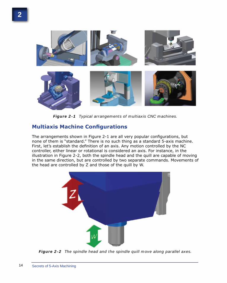
Figure 2-1 Typical arrangements of multiaxis CNC machines.
Multiaxis Machine Configurations
The arrangements shown in Figure 2-1 are all very popular configurations, but none of them is “standard.” There is no such thing as a standard 5-axis machine. First, let’s establish the definition of an axis. Any motion controlled by the NC controller, either linear or rotational is considered an axis. For instance, in the illustration in Figure 2-2, both the spindle head and the quill are capable of moving in the same direction, but are controlled by two separate commands. Movements of the head are controlled by Z and those of the quill by W.
Figure 2-2 The spindle head and the spindle quill move along parallel axes.

15Know Your Machine
2
The terms multiaxis and 5-axis are often used interchangeably and these terms can be confusing. The widely recognized term in the industry is 5-axis, but it is misleading because 9-axis standard possibilities exist – without adding additional sub-systems. In addition, a 4-axis machine is also considered to be a multiaxis machine. Despite the title of this book, the more accurate term multiaxis will often be used.
The following list provides the industry standard nomenclature for the basic 9-axis designations and directions.
XYZ are linear axes where Z is aligned with the spindle of the machine.
ABC are rotary axes rotating around XYZ respectively.
UVW are parallel linear axes along XYZ respectively.
45
Cutting Strategies
3
If drawings of the same multiaxis part were given to five different CNC programmers, chances are good that they would come up with five different methods to machine the part. This variability is a product of experience, available multiaxis equipment, available CAD/CAM systems, tooling, fixturing, material, and quantities.
What does every CNC programmer do when asked to write a program for a new part? He or she will create a mental image of the part, and based on the above factors, go through a variety of different scenarios to determine how to machine it. These decisions will include how to hold the part, and which side to start on. The programmer will then mentally go through the whole process of removing all the excess material from the starting stock in order to free the desired part from within it. Most programmers will brainstorm repeatedly and come up with multiple solutions, eliminating the weakest ones, adding new ideas, and then making the final decision. This whole process happens long before the creation of the actual toolpath. This pre-work meditation is the single most important part of the whole manufacturing process.
The process described above is the same, whether 3-axis or multiaxis work is being considered. The big difference is usually with the fixturing. Work holding is among the first decisions to be made when programming a 3-axis machine. Many multiaxis programmers will place the part data on a virtual machine. This process lets them levitate the part in the air and simulate the machine’s motions, without a fixture present, to see if all motions are possible without violating the machine’s work envelope boundaries. The part will be moved in space to achieve optimized, synchronized motions. Final fixture placement, or design, might be one of the last steps.
Of course this procedure is not always possible, but when a fixture is predetermined, additional effort will be needed to make sure there are no collisions between the fixture, tool, shank, arbor, or tool holder. Avoiding collisions is a big part of multiaxis programming. Collisions can occur not only during cutting, but also during tool changes, pallet changes, or manual retraction moves after an abrupt program stop. For example, after a power failure, the tool could be in a position where the only safe retraction move is simultaneous multiaxis motions.
65
Simultaneous Multiaxis Toolpaths
5
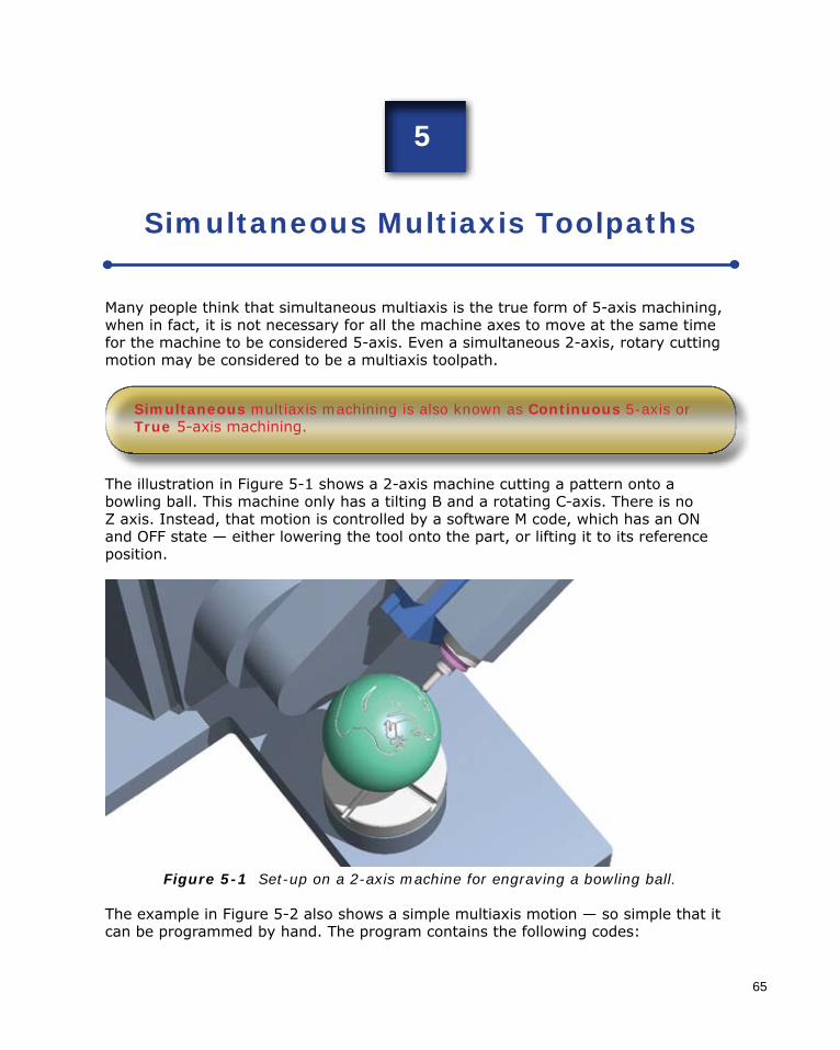
Many people think that simultaneous multiaxis is the true form of 5-axis machining, when in fact, it is not necessary for all the machine axes to move at the same time for the machine to be considered 5-axis. Even a simultaneous 2-axis, rotary cutting motion may be considered to be a multiaxis toolpath.
Simultaneous multiaxis machining is also known as Continuous 5-axis or True 5-axis machining.
The illustration in Figure 5-1 shows a 2-axis machine cutting a pattern onto a bowling ball. This machine only has a tilting B and a rotating C-axis. There is no Z axis. Instead, that motion is controlled by a software M code, which has an ON and OFF state — either lowering the tool onto the part, or lifting it to its reference position.
Figure 5-1 Set-up on a 2-axis machine for engraving a bowling ball.
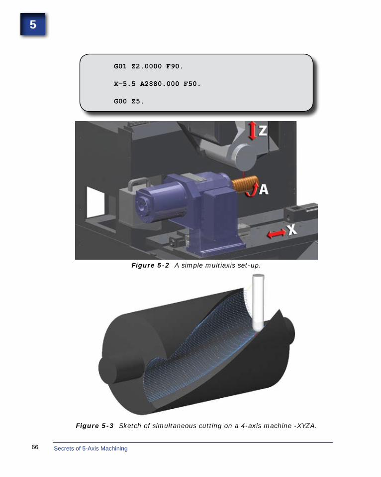
The example in Figure 5-2 also shows a simple multiaxis motion — so simple that it can be programmed by hand. The program contains the following codes:
66 Secrets of 5-Axis Machining
5
G01 Z2.0000 F90.
X-5.5 A2880.000 F50.
G00 Z5.
Figure 5-2 A simple multiaxis set-up.
Figure 5-3 Sketch of simultaneous cutting on a 4-axis machine -XYZA.

67Simultaneous Multiaxis Toolpaths
5
Figure 5-4 A 4-axis machine set-up for cutting a variable-pitch thread on an auger using motions on XYZ and A axes.
Simultaneous cutting on a 4-axis machine is shown in Figure 5-3, and a set-up for cutting a variable-pitch thread on an auger using 4-axis motions XYZ and A is shown in Figure 5-4.
Figure 5-5 illustrates a set-up on a similar machine, combining simultaneous motions, and using a flywheel to produce a knee-joint component using the 4-axis motions XYZ and C.
Figure 5-5 The 4-axis simultaneous motions XYZ and C are shown cutting a knee-joint, using a fly-cutter.
Many parts would be impossible to machine without simultaneous multiaxis motion. In the early days of multiaxis machining, many parts were designed around motion instead of as freeform CAD models.
116 Secrets of 5-Axis Machining
7
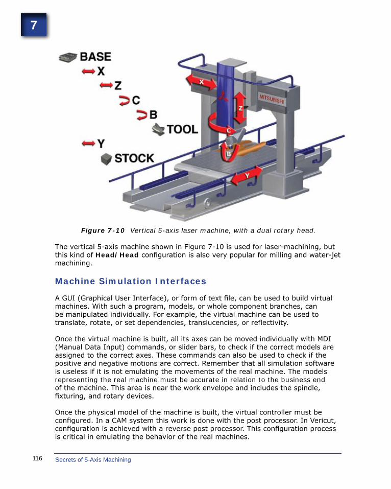
Figure 7-10 Vertical 5-axis laser machine, with a dual rotary head.
The vertical 5-axis machine shown in Figure 7-10 is used for laser-machining, but this kind of Head/Head configuration is also very popular for milling and water-jet machining.
Machine Simulation Interfaces
A GUI (Graphical User Interface), or form of text file, can be used to build virtual machines. With such a program, models, or whole component branches, can be manipulated individually. For example, the virtual machine can be used to translate, rotate, or set dependencies, translucencies, or reflectivity.
Once the virtual machine is built, all its axes can be moved individually with MDI (Manual Data Input) commands, or slider bars, to check if the correct models are assigned to the correct axes. These commands can also be used to check if the positive and negative motions are correct. Remember that all simulation software is useless if it is not emulating the movements of the real machine. The models representing the real machine must be accurate in relation to the business end of the machine. This area is near the work envelope and includes the spindle, fixturing, and rotary devices.
Once the physical model of the machine is built, the virtual controller must be configured. In a CAM system this work is done with the post processor. In Vericut, configuration is achieved with a reverse post processor. This configuration process is critical in emulating the behavior of the real machines.
117Machine Simulation
7
Using Machine Simulation
These days, very few people program exclusively by hand. Most people use a CAD/CAM system to generate code. The part is typically either designed or imported, and then toolpaths are generated using tools from an internal or an external library. Machine simulation can be run at any time during or at the end of this process, provided the groundwork has been laid down and the machines have been built.
The process of setting up machine simulation is very similar to setting up a real machine. The part must be placed on the machine in the correct orientation and then the Local Coordinate System needs to be set relative to the Machine Rotary Zero Position. The tools then need to be loaded into the magazine and the Tool Length Offsets must be set correctly. This work can be time-consuming if there is no direct interface between the CAD/CAM and the simulation programs. If there is a well-configured interface, or if the simulation is an intricate part of the CAD/CAM, then setting up will take only a few seconds of processing time.
Native CAD/CAM simulation loads tools from its libraries. Vericut uses its own tool manager, or it will build a tool library automatically if it is integrated with a CAM system. Once the part, tools, and toolpaths are loaded, the simulation is ready to be run, either as single blocks, or continuously. The simulation can be slowed down or sped, and the model can be dynamically rotated. Some systems allow movements forward or backward at any time, but others don’t offer this option. Some systems will show material removal with simulation, and some will permit analysis and measurement of the virtual part. Most systems will signal if there is a near-miss or collision between any configured components. They will also display an alarm if the limit switches are hit by over-travelling on any of the motion axes. Operators are able to see through models by making them invisible, which allows examination of the cutting process in ways that are not possible on a real machine.
There are many benefits to machine simulation, which allows different ideas to be tested out without pressure. Estimated program cycle times can be accessed, to help determine the best one. Crashing a machine on the computer screen is not a big concern, whereas crashing a real one is a catastrophe. But not using a multiaxis machine to its full potential is a shame. Simulation allows the best ideas from different cutting strategies, and the most efficient motion for any specific machine to be combined.
The process of setting up machine simulation is very similar to setting up a real machine. The part must be placed on the machine in the correct orientation and then the Local Coordinate System needs to be set relative to the Machine Rotary Zero Position.

169
IndexAABC linear axes, 15Absolute coordinate system, 57Accuracy, 9Active coordinate systems, 25 - 27, 57, 59-61, 140Actual part zero point, 27Aligned universe, 62Avoiding collisions, 45Automatic tool changing, 16, 42-3Axes, 3Axis defined,14 substitution, 32
BBall-nose cutters, 10, 96, 130Bettersurfacefinishes,10
CCAD/CAM systems, 3, 7, 27, capabilities, 139 multiaxis considerations, 139 origin, 60 selecting, 137 software development, 145 researching, 146 training, 144Calculating pivot distance (PD), 33, 37-8, 169CAM, multiaxis, 139Cam-operated multiaxis machines, 3Changeable spindle heads, 53Checking positioning repeatability, 42Circular interpolation, 73 tolerance, 74Clean core, 92CNC controllers, 3, 76 capabilities, 13, 157 drive systems, 13Collision avoidance (see Avoiding collisions)Common misconceptions, 4, 6, 7Complexity of work, 120Computer numerical control, 3, 92Crashing, 117Cut pattern, 79, 86-94, 140, 161
Cutting control, 97 direction, 100 strategies, 45, 70, 103, 117, 138, 167 variable-pitch thread, 67 DDedicated multiaxis machines, 9, 10Designations and directions of multiaxis machine
movements, 15Desired cutter area, engaging,10Dovetail effect, 98Dynamic control of tool axis, 90, 98 rotaryfixtureoffset,16,27-8,36
EEffective work envelope, 16Engaging desired cutter area, 10Extrusion milling machine, 123
FFanuc program, 34Feedrate, 72 dynamic changes, 138 inverse time, 74-6 optimization, 138 standard time, 74Finding the center of rotation, 21, 27-8 pivot distance, 33, 36-9, 161, 164 XY zero, 235-axis machine terms, 13 vector lines, 76, 1594-axis machines, 39 positioning, 7Fixtures, 47
GGage length (GL), 36-9, 161 tower, 24, 163Gantry type head/head machines, 122, 134G-codes, 29, 30, 56, 104-106
170 Secrets of 5-Axis Machining
MMachine
active coordinate system, 25-7, 57-61, 140, 159building virtual, 64, 113-6, 116-7, 139, 143-4, 167
business end, 64, 107, 125coordinate systems, 25-7, 56-7, 61-2, 140, 159
home position, 16, 57, 60, 78, 157 local coordinate systems, 25, 26, 61 rotary center point, 60 home position (MRHP), 17
zero point, 21, 25-7, 36, 60-2, 71-2, 144zero position (MRZP), 16-7, 21, 25, 27, 36,
117, 158-9, 162simulation, 27, 63-4, 98, 103-6, 143, 165-7
graphical user interfaces, 116 using, 117Machining centerconfiguration,108-110 complex workpieces, 5 engine components, 20 profiling,115 program, 29 routines, 5, 104, 138 spiral bevel gears, 68Machsim software, 106Maintenance issues, 40Manual data input (MDI), 25, 116Master coordinate system, 60 zero, 26M-code, 21, 43, 60Millingmachineswithfiveormoreaxes,43Modeling, 62-4, 71, 101, 111, 107-8, 116, 137-9, 159Multiaxis machines, 3-6, 8, 17-9, 40, 74, 124, 153 cam type, 3, 140 dedicated, 6, 9-10, 21, 39, 52-3, 110, 120 designations and directions, 15 physical properties, 13, 156 roughing, 21, 101, 130, 140-2, 166Multiple nesting, 58, 61
NNesting positions, 25, 26, 56-8, 61New possibilities, 11, 121Numbers of parts, 120
simulation, 105 G-90 code, 29, 30G-91 code, 29, 30Graphical user interface, 116
HHead/head multiaxis machines, 18, 36-7, 115-6,
121-2, 134, 156, 164 bridge type, 122 gantry type, 122, 134 laser cutting machine, 116, 135 water-jet milling machine, 116, 134Head/table multiaxis machines, 18, 31, 36, 113-4, 123-4, 155 aerospace, automotive applications, 129, 133 milling engine head ports, 125 milling long rotary parts, 124 mold and die applications, 130 nutating head combinations, 129 rotary table, tilting head, 128-30 variousconfigurations,124-9 with long X-axis travel, 123How CNC machines work, 56History of 5-axis machining, 3
IIndexing, 21, 44, 51, 55, 133 fixtures,51 methods, 51 toolpaths, 49 with rotary devices, 52 work, 49, 55Industrial robots, 135Interpolation circular, 73 linear, 73Inverse time feedrate, 72-4, 76
LLaser scanners, 95Lead and lag in milling, 100Limitations, 46Linear axis, 14-6, 34, 49, 74, 106, 121, 166 interpolation, 73Local coordinate systems, 25-7, 56-8, 61-2, 117

171Index
Numerical control, 3
OOld school simulation, 104One zero method, 60Optimum work envelope, 70Origin, 26, 60
PPallet changers, 40, 54, 107-8Part datum, 17, 21, 27, 58, 158 zero point (PZP), 27-8Plunge roughing, 101-2, 142Point clouds, 95Probes and probing, 94-5, 103-4 sub-routines, 104Physical properties of 5-axis machines, 13Pivot distance, 33 point, 37-9Pivoting spindle heads, 18, 32-6, 38, 124, 156, 166Pocket milling, 5, 86, 121, 137-9Positioning work, 5, 7, 8, 13, 20-1, 26, 42, 49, 52, 159, 166Post
processing, 3, 4, 8, 34, 40, 76-8, 103-6, 138, 143-7, 159, 166
processor, 3, 4, 8, 39, 40, 76-9, 104-6, 116, 138, 143, 147, 159 Probing routines, 104-5Program manual editing, 104 subroutines, 9, 43-4, 104
zero position (PZP), 16-8, 25, 32, 117, 158-9, 162Programming, 3, 5, 18, 26, 45-6, 56, 62, 71, 103, 105, 138, 144, 147 considerations, 46 languages, 3 limitations, 46
QQuestions and answers, 46, 144, 147, 149 physical positions, 151, 157 standard axis convention, 150, 154
RRepeating patterns, 104Rotary and pivoting axes, 32, 74
axis, 16, 21, 33, 42, 60, 71, 74, 107, 121, 156 devices, 16, 18, 21, 51-2, 116, 155 indexing mechanisms, 5, 54
mechanisms, 6, 19, 20, 39, 40-3, 52-3, 71 tool control point (RTCP), 33-4, 36, 161
zero positions, 16Rotary tables, 5, 8, 9, 18, 24, 27-8, 31-2, 130-2, 155-6, 163 brakes, 21, 40, 52, 104
devices, 16, 18-9, 21, 51-2, 77, 109, 116, 126, 155dynamicfixtureoffset(RTDFO),16,27-8,36
single and dual, 6, 8, 18, 39, 119Roughing, 11, 21, 101-2, 130, 140-2, 152, 166Routines, 5, 40, 42, 104-5
SSecond rotary table, 18Selecting machines, 119Selecting software, 137Simulation, 19, 27, 47, 63-4, 98, 103-17, 138, 166-7Simultaneous cutting motions, 10, 71 milling techniques, 21
multiaxis toolpath controls, 79, 101, 152, 161toolpaths, 5, 48, 65, 78, 103, 105, 107, 121
Special-purpose software, 137Spindle heads, changeable, 31, 53Spiral splines, 99Stacked errors, 9Standard multiaxis nomenclature, 15Stock (material) options, 47, 102 recognition, 142Sub-routines, 3, 43, 104Surfacefinishes,better,5,10System origin, 60 view, 27
TTable/table multiaxis machines, 18-9, 24, 110, 125, 132, 155, 162 with port-milling attachment, 125
172 Secrets of 5-Axis Machining
trunnionandrockandrollfixtures,71,111,132 various applications, 1333D surfacing toolpaths, 5Tilting spindle heads, 31Tombstonefixtures,6,40,58-9,108Tool
axis control, 79, 86, 89, 91-2, 98, 139, 141, 161, length offsets, 18, 24, 117 lists, 46, 140, 145 paths for lathes, 138 simultaneous, 65 plane with origin, 27 tip control, 79, 90-91, 141Tradeshows, 146Training, 1442 + 3 positioning, 49
UUsing motions XYZ and C, 67Unlocked rotary drives, 11UVW linear axes, 15
VVericut software, 1, 95, 106, 116-117Verificationsystem,27,104Visiting software companies, 1, 146-7Virtual machine, 103, 105 building, 106 components and models, 107 configuringforsimulation,105 kinematic component tree, 107 skeleton, 106
WWire frames, 79, 103, 139-40World zero, 26, 60
XXYZ linear axes, 15, 32, 66-7, 74
ZZeroing the indicator, 22 Zero position, 17, 21, 117, 158, 162 Z-Maximum, 37 Z-Minimum, 38
