book software ex series system setup
TRANSCRIPT

7/23/2019 Book Software Ex Series System Setup
http://slidepdf.com/reader/full/book-software-ex-series-system-setup 1/98
JUNOS® Software Guide for EX Series Ethernet Switches
JUNOS® Software Guide for EX Series Ethernet Switches,
Release 9.6: System Setup
Juniper Networks, Inc.
1194 North Mathilda Avenue
Sunnyvale, California 94089
USA
408-745-2000
www.juniper.net
Revision
Published: 2009-08-05

7/23/2019 Book Software Ex Series System Setup
http://slidepdf.com/reader/full/book-software-ex-series-system-setup 2/98
This product includes the Envoy SNMP Engine, developed by Epilogue Technology, an Integrated Systems Company. Copyright © 1986-1997, EpilogueTechnology Corporation. All rights reserved. This program and i ts documentation were developed at private expense, and no part of them is in the publicdomain.
This product includes memory allocation software developed by Mark Moraes, copyright © 1988, 1989, 1993, University of Toronto.
This product includes FreeBSD software developed by the University of California, Berkeley, and its contributors. All of the documentation and softwareincluded in the 4.4BSD and 4.4BSD-Lite Releases is copyrighted by the Regents of the University of California. Copyright © 1979, 1980, 1983, 1986, 1988,1989, 1991, 1992, 1993, 1994. The Regents of the University of California. All rights reserved.
GateD software copyright © 1995, the Regents of the University. All rights reserved. Gate Daemon was originated and developed through release 3.0 byCornell University and its collaborators. Gated is based on Kirton’s EGP, UC Berkeley’s routing daemon (routed), and DCN’s HELLO routing protocol.Development of Gated has been supported in part by the National Science Foundation. Portions of the GateD software copyright © 1988, Regents of theUniversity of California. All rights reserved. Portions of the GateD software copyright © 1991, D. L. S. Associates.
This product includes software developed by Maker Communications, Inc., copyright © 1996, 1997, Maker Communications, Inc.
Juniper Networks, the Juniper Networks logo, JUNOS, NetScreen, ScreenOS, and Steel-Belted Radius are registered trademarks of Juniper Networks, Inc. inthe United States and other countries. JUNOSe is a trademark of Juniper Networks, Inc. All other trademarks, service marks, registered trademarks, orregistered service marks are the property of their respective owners.
Juniper Networks assumes no responsibility for any inaccuracies in this document. Juniper Networks reserves the right to change, modify, transfer, orotherwise revise this publication without notice.
Products made or sold by Juniper Networks or components thereof might be covered by one or more of the following patents that are owned by or licensedto Juniper Networks: U.S. Patent Nos. 5,473,599, 5,905,725, 5,909,440, 6,192,051, 6,333,650, 6,359,479, 6,406,312, 6,429,706, 6,459,579, 6,493,347,6,538,518, 6,538,899, 6,552,918, 6,567,902, 6,578,186, and 6,590,785.
JUNOS® Software Guide for EX Series Ethernet Switches JUNOS® Software Guide for EX Series Ethernet Switches, Release 9.6: System Setup
Copyright © 2009, Juniper Networks, Inc.All rights reserved. Printed in USA.
Writing:Editing:Illustration:Cover Design:
Revision History5 August 2009—Revision 1
The information in this document is current as of the date listed in the revision history.
ii ■

7/23/2019 Book Software Ex Series System Setup
http://slidepdf.com/reader/full/book-software-ex-series-system-setup 3/98
END USER LICENSE AGREEMENT
READ THIS END USER LICENSE AGREEMENT (“AGREEMENT”) BEFORE DOWNLOADING, INSTALLING, OR USING THE SOFTWARE. BY DOWNLOADING,INSTALLING, OR USING THE SOFTWARE OR OTHERWISE EXPRESSING YOUR AGREEMENT TO THE TERMS CONTAINED HEREIN, YOU (AS CUSTOMER OR IF YOU ARE NOT THE CUSTOMER, AS A REPRESENTATIVE/AGENT AUTHORIZED TO BIND THE CUSTOMER) CONSENT TO BE BOUND BY THIS
AGREEMENT. IF YOU DO NOT OR CANNOT AGREE TO THE TERMS CONTAINED HEREIN, THEN (A) DO NOT DOWNLOAD, INSTALL, OR USE THE SOFTWARE,AND (B) YOU MAY CONTACT JUNIPER NETWORKS REGARDING LICENSE TERMS.
1. The Parties. The parties to this Agreement are (i) Juniper Networks, Inc. (if the Customer’s principal office is located in the Americas) or Juniper Networks(Cayman) Limited (if the Customer’s principal office is located outside the Americas) (such applicable entity being referred to herein as “ Juniper”), and (ii)the person or organization that originally purchased from Juniper or an authorized Juniper reseller the applicable license(s) for use of the Software (“Customer”)(collectively, the “Parties”).
2. The Software. In this Agreement, “Software” means the program modules and features of the Juniper or Juniper-supplied software, for which Customerhas paid the applicable license or support fees to Juniper or an authorized Juniper reseller, or which was embedded by Juniper in equipment which Customerpurchased from Juniper or an authorized Juniper reseller. “Software” also includes updates, upgrades and new releases of such software. “EmbeddedSoftware” means Software which Juniper has embedded in or loaded onto the Juniper equipment and any updates, upgrades, additions or replacementswhich are subsequently embedded in or loaded onto the equipment.
3. License Grant. Subject to payment of the applicable fees and the limitations and restrictions set forth herein, Juniper grants to Customer a non-exclusiveand non-transferable license, without right to sublicense, to use the Software, in executable form only, subject to the following use restrictions:
a. Customer shall use Embedded Software solely as embedded in, and for execution on, Juniper equipment originally purchased by Customer from Juniperor an authorized Juniper reseller.
b. Customer shall use the Software on a single hardware chassis having a single processing unit, or as many chassis or processing units for which Customerhas paid the applicable license fees; provided, however, with respect to the Steel-Belted Radius or Odyssey Access Client software only, Customer shall usesuch Software on a single computer containing a single physical random access memory space and containing any number of processors. Use of theSteel-Belted Radius or IMS AAA software on multiple computers or virtual machines (e.g., Solaris zones) requires multiple licenses, regardless of whethersuch computers or virtualizations are physically contained on a single chassis.
c. Product purchase documents, paper or electronic user documentation, and/or the particular licenses purchased by Customer may specify limits toCustomer’s use of the Software. Such limits may restrict use to a maximum number of seats, registered endpoints, concurrent users, sessions, calls,connections, subscribers, clusters, nodes, realms, devices, links, ports or transactions, or require the purchase of separate licenses to use particular features,functionalities, services, applications, operations, or capabilities, or provide throughput, performance, configuration, bandwidth, interface, processing,temporal, or geographical limits. In addition, such limits may restrict the use of the Software to managing certain kinds of networks or require the Softwareto be used only in conjunction with other specific Software. Customer’s use of the Software shall be subject to all such limitations and purchase of all applicablelicenses.
d. For any trial copy of the Software, Customer’s right to use the Software expires 30 days after download, installation or use of the Software. Customermay operate the Software after the 30-day trial period only if Customer pays for a license to do so. Customer may not extend or create an additional trialperiod by re-installing the Software after the 30-day trial period.
e. The Global Enterprise Edition of the Steel-Belted Radius software may be used by Customer only to manage access to Customer’s enterprise network.Specifically, service provider customers are expressly prohibited from using the Global Enterprise Edition of the Steel-Belted Radius software to support anycommercial network access services.
The foregoing license is not transferable or assignable by Customer. No license is granted herein to any user who did not originally purchase the applicablelicense(s) for the Software from Juniper or an authorized Juniper reseller.
4. Use Prohibitions. Notwithstanding the foregoing, the l icense provided herein does not permit the Customer to, and Customer agrees not to and shallnot: (a) modify, unbundle, reverse engineer, or create derivative works based on the Software; (b) make unauthorized copies of the Software (except asnecessary for backup purposes); (c) rent, sell, transfer, or grant any rights in and to any copy of the Software, in any form, to any third party; (d) removeany proprietary notices, labels, or marks on or in any copy of the Software or any product in which the Software is embedded; (e) dist ribute any copy of the Software to any third party, including as may be embedded in Juniper equipment sold in the secondhand market; (f) use any ‘locked’ or key-restricted
feature, function, service, application, operation, or capability without first purchasing the applicable license(s) and obtaining a valid key from Juniper, evenif such feature, function, service, application, operation, or capability is enabled without a key; (g) distribute any key for the Software provided by Juniperto any third party; (h) use the Software in any manner that extends or is broader than the uses purchased by Customer from Juniper or an authorized Juniperreseller; (i) use Embedded Software on non-Juniper equipment; (j) use Embedded Software (or make it available for use) on Juniper equipment that theCustomer did not originally purchase from Juniper or an authorized Juniper reseller; (k) disclose the results of testing or benchmarking of the Software toany third party without the prior written consent of Juniper; or (l) use the Software in any manner other than as expressly provided herein.
5. Audit. Customer shall maintain accurate records as necessary to verify compliance with this Agreement. Upon request by Juniper, Customer shall furnishsuch records to Juniper and certify its compliance with this Agreement.
■ iii
7/23/2019 Book Software Ex Series System Setup
http://slidepdf.com/reader/full/book-software-ex-series-system-setup 4/98
6. Confidentiality. The Parties agree that aspects of the Software and associated documentation are the confidential property of Juniper. As such, Customershall exercise all reasonable commercial efforts to maintain the Software and associated documentation in confidence, which at a minimum includesrestricting access to the Software to Customer employees and contractors having a need to use the Software for Customer’s internal business purposes.
7. Ownership. Juniper and Juniper’s licensors, respectively, retain ownership of all right, title, and interest (including copyright) in and to the Software,
associated documentation, and all copies of the Software. Nothing in this Agreement constitutes a transfer or conveyance of any right, title, or interest inthe Software or associated documentation, or a sale of the Software, associated documentation, or copies of the Software.
8. Warranty, Limitation of Liability, Disclaimer of Warranty. The warranty applicable to the Software shall be as set forth in the warranty statement thataccompanies the Software (the “Warranty Statement”). Nothing in this Agreement shall give rise to any obligation to support the Software. Support servicesmay be purchased separately. Any such support shall be governed by a separate, written support services agreement. TO THE MAXIMUM EXTENT PERMITTEDBY LAW, JUNIPER SHALL NOT BE LIABLE FOR ANY LOST PROFITS, LOSS OF DATA, OR COSTS OR PROCUREMENT OF SUBSTITUTE GOODS OR SERVICES,OR FOR ANY SPECIAL, INDIRECT, OR CONSEQUENTIAL DAMAGES ARISING OUT OF THIS AGREEMENT, THE SOFTWARE, OR ANY JUNIPER OR JUNIPER-SUPPLIED SOFTWARE. IN NO EVENT SHALL JUNIPER BE LIABLE FOR DAMAGES ARISING FROM UNAUTHORIZED OR IMPROPER USE OF ANY JUNIPER OR JUNIPER-SUPPLIED SOFTWARE. EXCEPT AS EXPRESSLY PROVIDED IN THE WARRANTY STATEMENT TO THE EXTENT PERMITTED BY LAW, JUNIPER DISCLAIMS ANY AND ALL WARRANTIES IN AND TO THE SOFTWARE (WHETHER EXPRESS, IMPLIED, STATUTORY, OR OTHERWISE), INCLUDINGANY IMPLIED WARRANTY OF MERCHANTABILITY, FITNESS FOR A PARTICULAR PURPOSE, OR NONINFRINGEMENT. IN NO EVENT DOES JUNIPER WARRANT THAT THE SOFTWARE, OR ANY EQUIPMENT OR NETWORK RUNNING THE SOFTWARE, WILL OPERATE WITHOUT ERROR OR INTERRUPTION,OR WILL BE FREE OF VULNERABILITY TO INTRUSION OR ATTACK. In no event shall Juniper’s or its suppliers’ or licensors’ liability to Customer, whetherin contract, tort (including negligence), breach of warranty, or otherwise, exceed the price paid by Customer for the Software that gave rise to the claim, orif the Software is embedded in another Juniper product, the price paid by Customer for such other product. Customer acknowledges and agrees that Juniperhas set its prices and entered into this Agreement in reliance upon the disclaimers of warranty and the limitations of liability set forth herein, that the same
reflect an allocation of risk between the Parties (including the risk that a contract remedy may fail of its essential purpose and cause consequential loss),and that the same form an essential basis of the bargain between the Parties.
9. Termination. Any breach of this Agreement or failure by Customer to pay any applicable fees due shall result in automatic termination of the licensegranted herein. Upon such termination, Customer shall destroy or return to Juniper all copies of the Software and related documentation in Customer’spossession or control.
10. Taxes. All license fees payable under this agreement are exclusive of tax. Customer shall be responsible for paying Taxes arising from the purchase of the license, or importation or use of the Software. If applicable, valid exemption documentation for each taxing jurisdiction shall be provided to Juniper priorto invoicing, and Customer shall promptly notify Juniper if their exemption is revoked or modified. All payments made by Customer shall be net of anyapplicable withholding tax. Customer will provide reasonable assistance to Juniper in connection with such withholding taxes by promptly: providing Juniperwith valid tax receipts and other required documentation showing Customer’s payment of any withholding taxes; completing appropriate applications thatwould reduce the amount of withholding tax to be paid; and notifying and assisting Juniper in any audit or tax proceeding related to transactions hereunder.Customer shall comply with all applicable tax laws and regulations, and Customer will promptly pay or reimburse Juniper for all costs and damages relatedto any liability incurred by Juniper as a result of Customer’s non-compliance or delay with its responsibilities herein. Customer’s obligations under thisSection shall survive termination or expiration of this Agreement.
11. Export. Customer agrees to comply with all applicable export laws and restrictions and regulations of any United States and any applicable foreignagency or authority, and not to export or re-export the Software or any direct product thereof in violation of any such restrictions, laws or regulations, orwithout all necessary approvals. Customer shall be liable for any such violations. The version of the Software supplied to Customer may contain encryptionor other capabilities restricting Customer’s ability to export the Software without an export license.
12. Commercial Computer Software. The Software is “commercial computer software” and is provided with restricted rights. Use, duplication, or disclosureby the United States government is subject to restrictions set forth in this Agreement and as provided in DFARS 227.7201 through 227.7202-4, FAR 12.212,FAR 27.405(b)(2), FAR 52.227-19, or FAR 52.227-14(ALT III) as applicable.
13. Interface Information. To the extent required by applicable law, and at Customer's written request, Juniper shall provide Customer with the interfaceinformation needed to achieve interoperability between the Software and another independently created program, on payment of applicable fee, if any.Customer shall observe strict obligations of confidentiality with respect to such information and shall use such information in compliance with any applicableterms and conditions upon which Juniper makes such information available.
14. Third Party Software. Any licensor of Juniper whose software is embedded in the Software and any supplier of Juniper whose products or technologyare embedded in (or services are accessed by) the Software shall be a third party beneficiary with respect to this Agreement, and such licensor or vendor
shall have the right to enforce this Agreement in its own name as if it were Juniper. In addition, certain third party software may be provided with theSoftware and is subject to the accompanying license(s), if any, of its respective owner(s). To the extent portions of the Software are distributed under andsubject to open source licenses obligating Juniper to make the source code for such portions publicly available (such as the GNU General Public License(“GPL”) or the GNU Library General Public License (“LGPL”)), Juniper will make such source code portions (including Juniper modifications, as appropriate)available upon request for a period of up to three years from the date of distribution. Such request can be made in writing to Juniper Networks, Inc., 1194
N. Mathilda Ave., Sunnyvale, CA 94089, ATTN: General Counsel. You may obtain a copy of the GPL at http://www.gnu.org/licenses/gpl.html, and
a copy of the LGPL at http://www.gnu.org/licenses/lgpl.html.
15. Miscellaneous. This Agreement shall be governed by the laws of the State of California without reference to its conflicts of laws principles. The provisionsof the U.N. Convention for the International Sale of Goods shall not apply to this Agreement. For any disputes arising under this Agreement, the Partieshereby consent to the personal and exclusive jurisdiction of, and venue in, the state and federal courts within Santa Clara County, California. This Agreementconstitutes the entire and sole agreement between Juniper and the Customer with respect to the Software, and supersedes all prior and contemporaneous
iv ■

7/23/2019 Book Software Ex Series System Setup
http://slidepdf.com/reader/full/book-software-ex-series-system-setup 5/98
agreements relating to the Software, whether oral or written (including any inconsistent terms contained in a purchase order), except that the terms of aseparate written agreement executed by an authorized Juniper representative and Customer shall govern to the extent such terms are inconsistent or conflictwith terms contained herein. No modification to this Agreement nor any waiver of any rights hereunder shall be effective unless expressly assented to inwriting by the party to be charged. If any portion of this Agreement is held invalid, the Parties agree that such invalidity shall not affect the validity of theremainder of this Agreement. This Agreement and associated documentation has been written in the English language, and the Parties agree that the English
version will govern. (For Canada: Les parties aux présentés confirment leur volonté que cette convention de même que tous les documents y compris toutavis qui s'y rattaché, soient redigés en langue anglaise. (Translation: The parties confirm that this Agreement and all related documentation is and will bein the English language)).
■ v

7/23/2019 Book Software Ex Series System Setup
http://slidepdf.com/reader/full/book-software-ex-series-system-setup 6/98
vi ■
7/23/2019 Book Software Ex Series System Setup
http://slidepdf.com/reader/full/book-software-ex-series-system-setup 7/98
Table of Contents
About This Topic Collection xi
How to Use This Guide ................................................................................... xiList of EX Series Guides for JUNOS Release 9.6 .............................................. xiDownloading Software ................................................................................. xiiiDocumentation Symbols Key ....................................................................... xiiiDocumentation Feedback .............................................................................. xvRequesting Technical Support ........................................................................ xv
Self-Help Online Tools and Resources ..................................................... xvOpening a Case with JTAC ...................................................................... xvi
Part 1 JUNOS Software for EX Series Switches
Chapter 1 JUNOS Software for EX Series Switches 3
JUNOS Software—Overview ............................................................................ 3EX Series Switch Software Features Overview .......................................... 3Understanding Software Infrastructure and Processes ............................ 12
Routing Engine and Packet Forwarding Engine ................................ 12 JUNOS Software Processes ............................................................... 13
JUNOS Configuration Tools ............................................................................ 14CLI User Interface Overview ................................................................... 14
CLI Overview .................................................................................... 14CLI Help and Command Completion ................................................ 15CLI Command Modes ....................................................................... 15
J-Web User Interface for EX Series Switches Overview ........................... 16Understanding J-Web Configuration Tools .............................................. 18Understanding J-Web User Interface Sessions ......................................... 19
Using the JUNOS Configuration Tools ............................................................ 19Starting the J-Web Interface .................................................................... 20Using the CLI Terminal ........................................................................... 20Using the Point and Click CLI Tool in the J-Web Interface to Edit
Configuration Text ............................................................................ 21Using the CLI Editor in the J-Web Interface to Edit Configuration
Text .................................................................................................. 23Dashboard for EX Series Switches .......................................................... 23
System Information Panel ................................................................ 24Health Status Panel .......................................................................... 24Capacity Utilization Panel ................................................................. 25
Table of Contents ■ vii
7/23/2019 Book Software Ex Series System Setup
http://slidepdf.com/reader/full/book-software-ex-series-system-setup 8/98
Alarms Panel .................................................................................... 25Chassis Viewer ................................................................................. 26
Chapter 2 Software Installation 31
JUNOS Software Installation .......................................................................... 31Understanding Software Installation on EX Series Switches .................... 31
Overview of the Software Installation Process .................................. 31Software Package Security ................................................................ 32Installing Software on a Virtual Chassis ............................................ 32Installing Software on EX8200 Switches with Redundant Routing
Engines ...................................................................................... 32Installing Software Using Automatic Software Download .................32Troubleshooting Software Installation .............................................. 33
JUNOS Software Package Names ............................................................ 33Understanding Autoinstallation of Configuration Files on EX Series
Switches ........................................................................................... 34Typical Uses for Autoinstallation ...................................................... 34Autoinstallation Configuration Files and IP Addresses ...................... 34Typical Autoinstallation Process on a New Switch ............................ 35
Installing JUNOS Software on EX Series Switches .......................................... 36Downloading Software Packages from Juniper Networks ........................ 36Installing Software on an EX Series Switch with a Single Routing Engine
(CLI Procedure) ................................................................................. 37Installing Software on an EX8200 Switch with Redundant Routing
Engines (CLI Procedure) ................................................................... 38Preparing the Switch for the Software Installation ............................ 39Installing Software on the Backup Routing Engine ............................ 40Installing Software on the Default Master Routing Engine ................41Returning Routing Control to the Default Master Routing Engine
(Optional) ................................................................................... 42Installing Software on EX Series Switches (J-Web Procedure) ..................43
Installing Software Upgrades from a Server ...................................... 43Installing Software Upgrades by Uploading Files .............................. 44
Booting an EX Series Switch Using a Software Package Stored on a USBFlash Drive ....................................................................................... 45
Configuring Autoinstallation of Configuration Files (CLI Procedure) ........46Upgrading Software Using Automatic Software Download on EX Series
Switches ........................................................................................... 48Verifying JUNOS Software Installation ........................................................... 49
Verifying Autoinstallation Status on an EX Series Switch ........................ 49
Verifying That Automatic Software Download Is Working Correctly .......49Troubleshooting JUNOS Software Installation ................................................ 50Troubleshooting Software Installation ..................................................... 50
Recovering from a Failed Software Upgrade on an EX SeriesSwitch ........................................................................................ 50
Rebooting from the Inactive Partition ............................................... 51Troubleshooting Loss of the Root Password ............................................ 52
viii ■ Table of Contents
JUNOS® Software Guide for EX Series Ethernet Switches, Release 9.6: System Setup

7/23/2019 Book Software Ex Series System Setup
http://slidepdf.com/reader/full/book-software-ex-series-system-setup 9/98
Chapter 3 Initial Configuration 55
Connecting and Configuring an EX Series Switch (CLI Procedure) .................55Connecting and Configuring an EX Series Switch (J-Web Procedure) .............57Configuring Date and Time for the EX Series Switch (J-Web Procedure) ........60Configuring System Identity for the EX Series Switch (J-Web Procedure) ......60EX3200 and EX4200 Default Configuration .................................................. 61
Chapter 4 License Management 67
Software Licenses in EX Series Switches—Overview ..................................... 67Software Licenses for the EX Series Switch Overview ............................. 67License Key Components for the EX Series Switch ................................. 68
Managing Software Licenses in EX Series Switches ....................................... 68
Managing Licenses for the EX Series Switch (CLI Procedure) ..................69Adding New Licenses ....................................................................... 69Deleting Licenses .............................................................................. 70Saving License Keys ......................................................................... 70
Managing Licenses for the EX Series Switch (J-Web Procedure) ..............70Adding New Licenses ....................................................................... 70Deleting Licenses .............................................................................. 71Displaying License Keys ................................................................... 71Downloading Licenses ...................................................................... 71
Registering the EX Series Switch with the J-Web Interface ...................... 72Monitoring Software Licenses in EX Series Switches ..................................... 72
Monitoring Licenses for the EX Series Switch .......................................... 72Displaying Installed Licenses and License Usage Details ...................72
Displaying License Usage ................................................................. 73Displaying Installed License Keys ..................................................... 73
Chapter 5 IP Address Management 75
IP Address Management Overview ................................................................ 75DHCP Services for EX Series Switches Overview .................................... 75DHCP/BOOTP Relay for EX Series Switches Overview ............................ 76
IP Address Management Configuration ......................................................... 76Configuring DHCP Services (J-Web Procedure) ........................................ 77
IP Address Management Monitoring ............................................................. 79Monitoring DHCP Services ...................................................................... 79
Table of Contents ■ ix
Table of Contents

7/23/2019 Book Software Ex Series System Setup
http://slidepdf.com/reader/full/book-software-ex-series-system-setup 10/98
x ■ Table of Contents
JUNOS® Software Guide for EX Series Ethernet Switches, Release 9.6: System Setup
7/23/2019 Book Software Ex Series System Setup
http://slidepdf.com/reader/full/book-software-ex-series-system-setup 11/98
About This Topic Collection
■ How to Use This Guide on page xi
■ List of EX Series Guides for JUNOS Release 9.6 on page xi
■ Downloading Software on page xiii
■ Documentation Symbols Key on page xiii
■ Documentation Feedback on page xv
■ Requesting Technical Support on page xv
How to Use This Guide
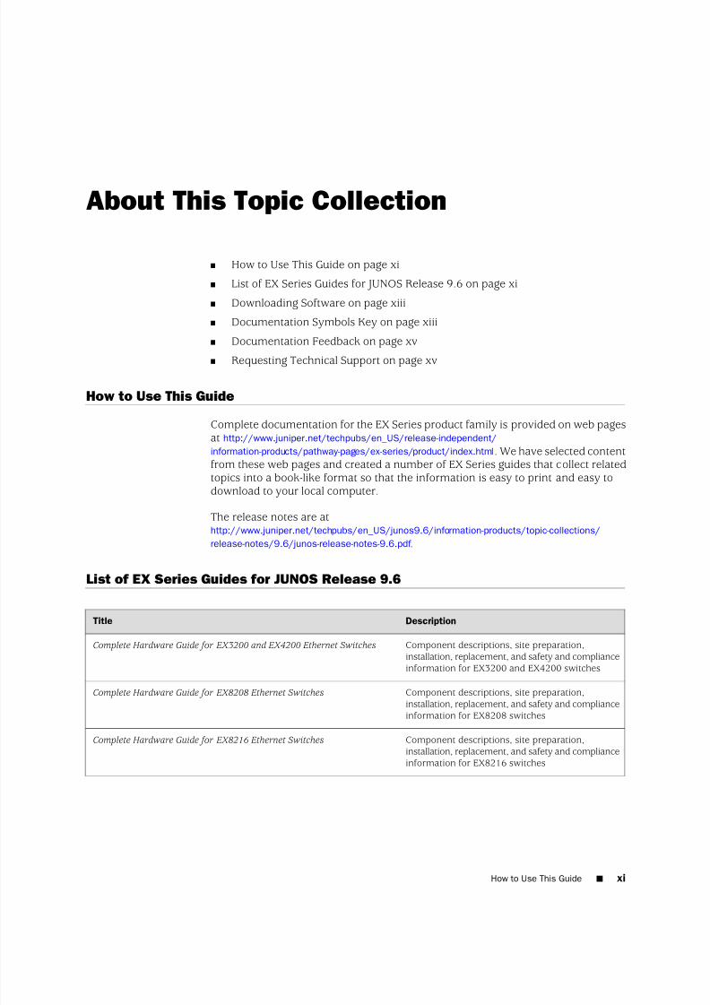
Complete documentation for the EX Series product family is provided on web pagesat http://www.juniper.net/techpubs/en_US/release-independent/
information-products/pathway-pages/ex-series/product/index.html. We have selected contentfrom these web pages and created a number of EX Series guides that collect relatedtopics into a book-like format so that the information is easy to print and easy todownload to your local computer.
The release notes are athttp://www.juniper.net/techpubs/en_US/junos9.6/information-products/topic-collections/release-notes/9.6/junos-release-notes-9.6.pdf .
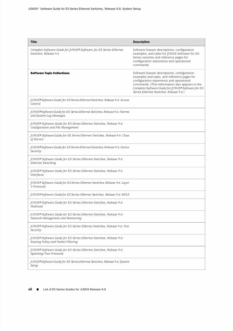
List of EX Series Guides for JUNOS Release 9.6
DescriptionTitle
Component descriptions, site preparation,installation, replacement, and safety and complianceinformation for EX3200 and EX4200 switches
Complete Hardware Guide for EX3200 and EX4200 Ethernet Switches
Component descriptions, site preparation,
installation, replacement, and safety and complianceinformation for EX8208 switches
Complete Hardware Guide for EX8208 Ethernet Switches
Component descriptions, site preparation,installation, replacement, and safety and complianceinformation for EX8216 switches
Complete Hardware Guide for EX8216 Ethernet Switches
How to Use This Guide ■ xi
7/23/2019 Book Software Ex Series System Setup
http://slidepdf.com/reader/full/book-software-ex-series-system-setup 12/98
DescriptionTitle
Software feature descriptions, configurationexamples, and tasks for JUNOS Software for EX
Series switches and reference pages forconfiguration statements and operationalcommands
Complete Software Guide for JUNOS® Software for EX Series Ethernet
Switches, Release 9.6
Software feature descriptions, configurationexamples and tasks, and reference pages forconfiguration statements and operationalcommands. (This information also appears in theComplete Software Guide for JUNOS® Software for EX
Series Ethernet Switches, Release 9.6.)
Software Topic Collections
JUNOS® Software Guide for EX Series Ethernet Switches, Release 9.6: AccessControl
JUNOS® Software Guide for EX Series Ethernet Switches, Release 9.6: Alarms
and System Log Messages
JUNOS® Software Guide for EX Series Ethernet Switches, Release 9.6:
Configuration and File Management
JUNOS® Software Guide for EX Series Ethernet Switches, Release 9.6: Classof Service
JUNOS® Software Guide for EX Series Ethernet Switches, Release 9.6: Device
Security
JUNOS® Software Guide for EX Series Ethernet Switches, Release 9.6: Ethernet Switching
JUNOS® Software Guide for EX Series Ethernet Switches, Release 9.6:
Interfaces
JUNOS® Software Guide for EX Series Ethernet Switches, Release 9.6: Layer
3 Protocols
JUNOS® Software Guide for EX Series Ethernet Switches, Release 9.6: MPLS
JUNOS® Software Guide for EX Series Ethernet Switches, Release 9.6:
Multicast
JUNOS® Software Guide for EX Series Ethernet Switches, Release 9.6:Network Management and Monitoring
JUNOS® Software Guide for EX Series Ethernet Switches, Release 9.6: Port
Security
JUNOS® Software Guide for EX Series Ethernet Switches, Release 9.6:
Routing Policy and Packet Filtering
JUNOS® Software Guide for EX Series Ethernet Switches, Release 9.6:Spanning-Tree Protocols
JUNOS® Software Guide for EX Series Ethernet Switches, Release 9.6: System
Setup
xii ■ List of EX Series Guides for JUNOS Release 9.6
JUNOS® Software Guide for EX Series Ethernet Switches, Release 9.6: System Setup
7/23/2019 Book Software Ex Series System Setup
http://slidepdf.com/reader/full/book-software-ex-series-system-setup 13/98
DescriptionTitle
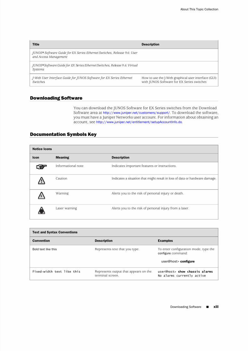
JUNOS® Software Guide for EX Series Ethernet Switches, Release 9.6: User
and Access Management
JUNOS® Software Guide for EX Series Ethernet Switches, Release 9.6: VirtualSystems
How to use the J-Web graphical user interface (GUI)with JUNOS Software for EX Series switches
J-Web User Interface Guide for JUNOS Software for EX Series Ethernet
Switches
Downloading Software
You can download the JUNOS Software for EX Series switches from the DownloadSoftware area at http://www.juniper.net/customers/support/. To download the software,you must have a Juniper Networks user account. For information about obtaining an
account, see http://www.juniper.net/entitlement/setupAccountInfo.do.
Documentation Symbols Key
Notice Icons
DescriptionMeaningIcon
Indicates important features or instructions.Informational note
Indicates a situation that might result in loss of data or hardware damage.Caution
Alerts you to the risk of personal injury or death.Warning
Alerts you to the risk of personal injury from a laser.Laser warning
Text and Syntax Conventions
ExamplesDescriptionConvention
To enter configuration mode, type theconfigure command:
user@host> configure
Represents text that you type.Bold text like this
user@host> show chassis alarms
No alarms currently active
Represents output that appears on theterminal screen.
Fixed-width text like this
Downloading Software ■ xiii
About This Topic Collection
7/23/2019 Book Software Ex Series System Setup
http://slidepdf.com/reader/full/book-software-ex-series-system-setup 14/98
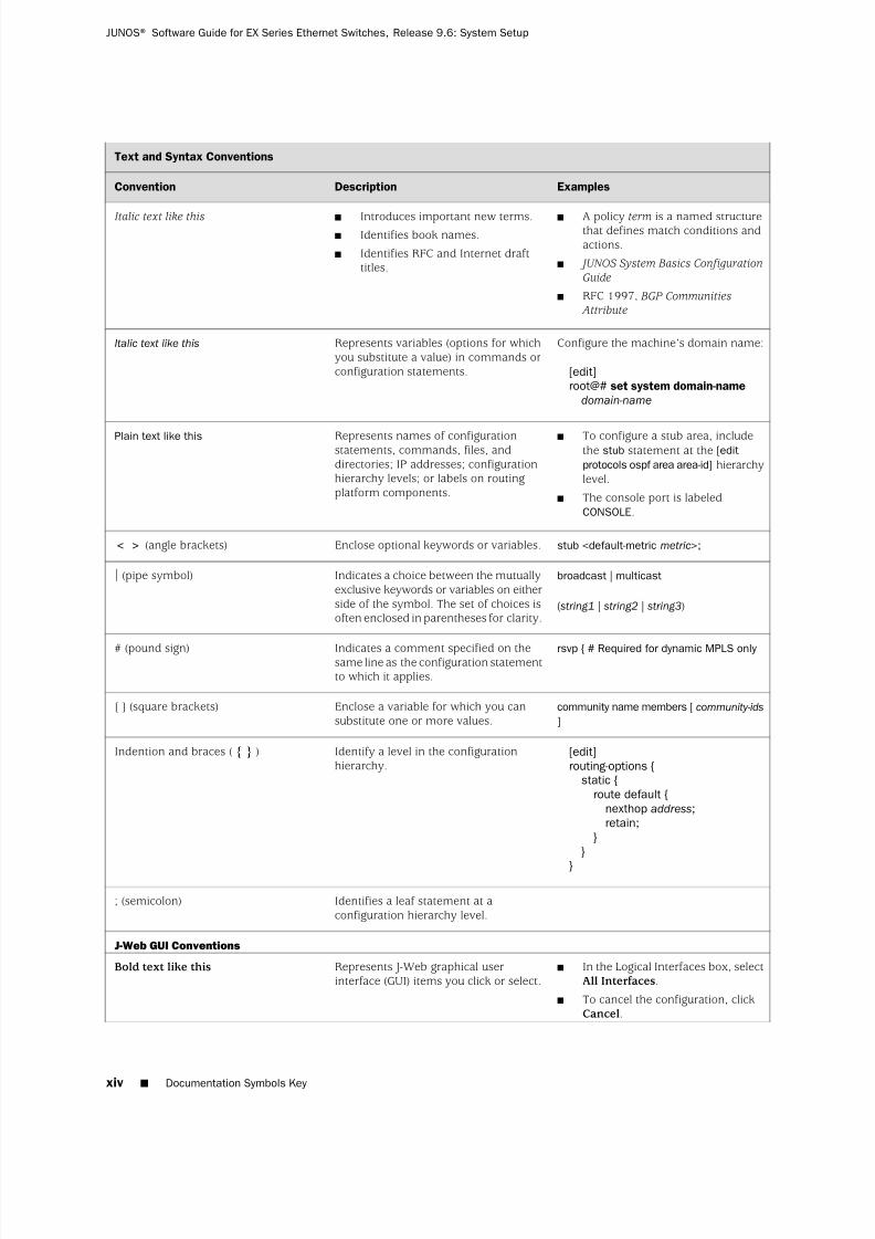
Text and Syntax Conventions
ExamplesDescriptionConvention
■ A policy term is a named structurethat defines match conditions andactions.
■ JUNOS System Basics Configuration
Guide
■ RFC 1997, BGP Communities Attribute
■ Introduces important new terms.■ Identifies book names.
■ Identifies RFC and Internet drafttitles.
Italic text like this
Configure the machine’s domain name:
[edit]root@# set system domain-name
domain-name
Represents variables (options for whichyou substitute a value) in commands orconfiguration statements.
Italic text like this
■ To configure a stub area, includethe stub statement at the [edit
protocols ospf area area-id] hierarchylevel.
■ The console port is labeledCONSOLE.
Represents names of configurationstatements, commands, files, anddirectories; IP addresses; configurationhierarchy levels; or labels on routingplatform components.
Plain text like this
stub <default-metric metric>;Enclose optional keywords or variables.< > (angle brackets)
broadcast | multicast
( string1 | string2 | string3)
Indicates a choice between the mutuallyexclusive keywords or variables on eitherside of the symbol. The set of choices isoften enclosed in parentheses for clarity.
| (pipe symbol)
rsvp { # Required for dynamic MPLS only Indicates a comment specified on thesame line as the configuration statementto which it applies.
# (pound sign)
community name members [ community-ids
]
Enclose a variable for which you cansubstitute one or more values.
[ ] (square brackets)
[edit]routing-options {
static {route default {
nexthop address;retain;
}}
}
Identify a level in the configurationhierarchy.
Indention and braces ( { } )
Identifies a leaf statement at aconfiguration hierarchy level.
; (semicolon)
J-Web GUI Conventions
■ In the Logical Interfaces box, selectAll Interfaces.
■ To cancel the configuration, clickCancel.
Represents J-Web graphical userinterface (GUI) items you click or select.
Bold text like this
xiv ■ Documentation Symbols Key
JUNOS® Software Guide for EX Series Ethernet Switches, Release 9.6: System Setup

7/23/2019 Book Software Ex Series System Setup
http://slidepdf.com/reader/full/book-software-ex-series-system-setup 15/98
Text and Syntax Conventions
ExamplesDescriptionConvention
In the configuration editor hierarchy,select Protocols>Ospf .
Separates levels in a hierarchy of J-Webselections.
> (bold right angle bracket)
Documentation Feedback
We encourage you to provide feedback, comments, and suggestions so that we canimprove the documentation. Send e-mail to [email protected] with thefollowing:
■ Document URL or title
■ Page number if applicable
■ Software version■ Your name and company
Requesting Technical Support
Technical product support is available through the Juniper Networks TechnicalAssistance Center (JTAC). If you are a customer with an active J-Care or JNASC supportcontract, or are covered under warranty, and need post-sales technical support, youcan access our tools and resources online or open a case with JTAC.
■ JTAC policies—For a complete understanding of our JTAC procedures and policies,review the JTAC User Guide located at
http://www.juniper.net/customers/support/downloads/710059.pdf .■ Product warranties—For product warranty information, visit
http://www.juniper.net/support/warranty/.
■ JTAC Hours of Operation —The JTAC centers have resources available 24 hoursa day, 7 days a week, 365 days a year.
Self-Help Online Tools and Resources
For quick and easy problem resolution, Juniper Networks has designed an onlineself-service portal called the Customer Support Center (CSC) that provides you withthe following features:
■ Find CSC offerings: http://www.juniper.net/customers/support/
■ Search for known bugs: http://www2.juniper.net/kb/
■ Find product documentation: http://www.juniper.net/techpubs/
■ Find solutions and answer questions using our Knowledge Base:http://kb.juniper.net/
■ Download the latest versions of software and review release notes:http://www.juniper.net/customers/csc/software/
Documentation Feedback ■ xv
About This Topic Collection

7/23/2019 Book Software Ex Series System Setup
http://slidepdf.com/reader/full/book-software-ex-series-system-setup 16/98
■ Search technical bulletins for relevant hardware and software notifications:https://www.juniper.net/alerts/
■ Join and participate in the Juniper Networks Community Forum:http://www.juniper.net/company/communities/
■ Open a case online in the CSC Case Management tool: http://www.juniper.net/cm/
To verify service entitlement by product serial number, use our Serial NumberEntitlement (SNE) Tool located at https://tools.juniper.net/SerialNumberEntitlementSearch/ .
Opening a Case with JTAC
You can open a case with JTAC on the Web or by telephone.
■ Use the Case Management tool in the CSC at http://www.juniper.net/cm/ .
■ Call 1-888-314-JTAC (1-888-314-5822 toll-free in the USA, Canada, and Mexico).
For international or direct-dial options in countries without toll-free numbers, seehttp://www.juniper.net/support/requesting support.html
xvi ■ Requesting Technical Support
JUNOS® Software Guide for EX Series Ethernet Switches, Release 9.6: System Setup

7/23/2019 Book Software Ex Series System Setup
http://slidepdf.com/reader/full/book-software-ex-series-system-setup 17/98
Part 1
JUNOS Software for EX Series Switches
■ JUNOS Software for EX Series Switches on page 3
■ Software Installation on page 31
■ Initial Configuration on page 55
■ License Management on page 67
■
IP Address Management on page 75
JUNOS Software for EX Series Switches ■ 1

7/23/2019 Book Software Ex Series System Setup
http://slidepdf.com/reader/full/book-software-ex-series-system-setup 18/98
2 ■ JUNOS Software for EX Series Switches
JUNOS® Software Guide for EX Series Ethernet Switches, Release 9.6: System Setup
7/23/2019 Book Software Ex Series System Setup
http://slidepdf.com/reader/full/book-software-ex-series-system-setup 19/98
Chapter 1
JUNOS Software for EX Series Switches
■ JUNOS Software—Overview on page 3
■ JUNOS Configuration Tools on page 14
■ Using the JUNOS Configuration Tools on page 19
JUNOS Software—Overview
■ EX Series Switch Software Features Overview on page 3
■ Understanding Software Infrastructure and Processes on page 12
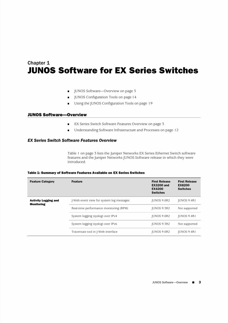
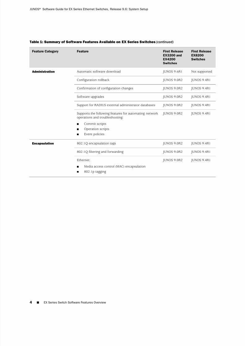
EX Series Switch Software Features Overview
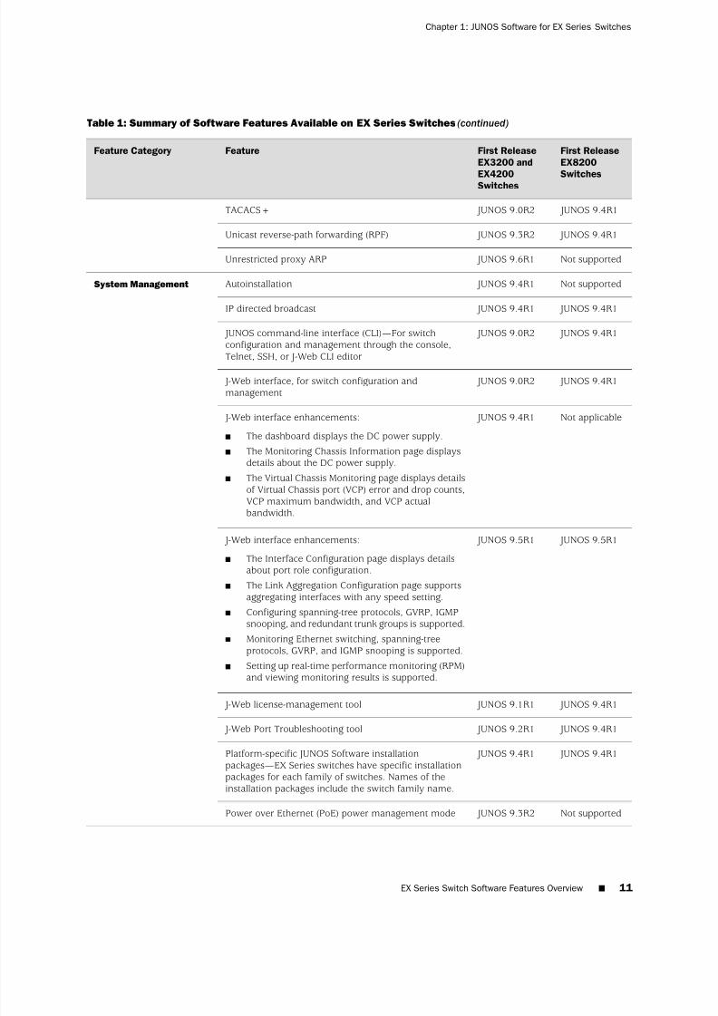
Table 1 on page 3 lists the Juniper Networks EX Series Ethernet Switch softwarefeatures and the Juniper Networks JUNOS Software release in which they wereintroduced.
Table 1: Summary of Software Features Available on EX Series Switches
First Release
EX8200
Switches
First Release
EX3200 and
EX4200
Switches
FeatureFeature Category
JUNOS 9.4R1 JUNOS 9.0R2 J-Web event view for system log messagesActivity Logging and
Monitoring
Not supported JUNOS 9.3R2Real-time performance monitoring (RPM)
JUNOS 9.4R1 JUNOS 9.0R2System logging (syslog) over IPv4
Not supported JUNOS 9.3R2System logging (syslog) over IPv6
JUNOS 9.4R1 JUNOS 9.0R2Traceroute tool in J-Web interface
JUNOS Software—
Overview ■ 3
7/23/2019 Book Software Ex Series System Setup
http://slidepdf.com/reader/full/book-software-ex-series-system-setup 20/98
Table 1: Summary of Software Features Available on EX Series Switches (continued)
First Release
EX8200
Switches
First Release
EX3200 and
EX4200Switches
FeatureFeature Category
Not supported JUNOS 9.6R1Automatic software downloadAdministration
JUNOS 9.4R1 JUNOS 9.0R2Configuration rollback
JUNOS 9.4R1 JUNOS 9.0R2Confirmation of configuration changes
JUNOS 9.4R1 JUNOS 9.0R2Software upgrades
JUNOS 9.4R1 JUNOS 9.0R2Support for RADIUS external administrator databases
JUNOS 9.4R1 JUNOS 9.0R2Supports the following features for automating networkoperations and troubleshooting:
■ Commit scripts
■ Operation scripts
■ Event policies
JUNOS 9.4R1 JUNOS 9.0R2802.1Q encapsulation tagsEncapsulation
JUNOS 9.4R1 JUNOS 9.0R2802.1Q filtering and forwarding
JUNOS 9.4R1 JUNOS 9.0R2Ethernet:
■ Media access control (MAC) encapsulation
■ 802.1p tagging
4 ■ EX Series Switch Software Features Overview
JUNOS® Software Guide for EX Series Ethernet Switches, Release 9.6: System Setup

7/23/2019 Book Software Ex Series System Setup
http://slidepdf.com/reader/full/book-software-ex-series-system-setup 21/98

7/23/2019 Book Software Ex Series System Setup
http://slidepdf.com/reader/full/book-software-ex-series-system-setup 22/98
Table 1: Summary of Software Features Available on EX Series Switches (continued)
First Release
EX8200
Switches
First Release
EX3200 and
EX4200Switches
FeatureFeature Category
JUNOS 9.4R1 JUNOS 9.3R2DHCP server and relay with option 82 for Layer 2 VLANsIP Address Management
Not supported JUNOS 9.3R2DHCPv6 and IPv6 DNS
JUNOS 9.4R1 JUNOS 9.0R2Dynamic Host Configuration Protocol (DHCP)
JUNOS 9.4R1 JUNOS 9.3R2Local DHCP server
JUNOS 9.4R1 JUNOS 9.0R2Static addresses
JUNOS 9.4R1 JUNOS 9.1R1BPDU protection for spanning-tree protocolsLayer 2 Network Protocols
Not supported JUNOS 9.6R1Extended Q-in-Q VLAN support for multiple S-VLANs peraccess interface, firewall-filter-based VLAN assignment,and routed VLAN interfaces (RVIs)
JUNOS 9.4R1 JUNOS 9.1R1GARP VLAN Registration Protocol (GVRP)
JUNOS 9.4R1 JUNOS 9.0R2Link Layer Discovery Protocol (LLDP)
Not supported JUNOS 9.0R2Link Layer Discovery Protocol-Media Endpoint Discovery(LLDP-MED) with voice over IP (VoIP) integration
JUNOS 9.4R1 JUNOS 9.1R1Loop protection for spanning-tree protocols
Not supported JUNOS 9.3R2Private VLANs (PVLANs)
Not supported JUNOS 9.3R2Q-in-Q tunneling
JUNOS 9.4R1 JUNOS 9.1R1Root protection for spanning-tree protocols
JUNOS 9.4R1 JUNOS 9.0R2Routed VLAN interfaces (RVIs)
JUNOS 9.4R1 JUNOS 9.0R2Spanning tree:
■ Spanning Tree Protocol (STP)
■ Rapid Spanning Tree Protocol (RSTP)
■ Multiple Spanning Tree Protocol (MSTP)
JUNOS 9.6R1 JUNOS 9.4R1Spanning tree:
■ VLAN Spanning Tree Protocol (VSTP)
JUNOS 9.4R1 JUNOS 9.1R1Storm control
Not supported JUNOS 9.3R2Unknown Layer 2 unicast forwarding
JUNOS 9.6R1 JUNOS 9.2R1Virtual routing and forwarding (VRF)—virtual routinginstances
JUNOS 9.4R1 JUNOS 9.2R1VLAN range
6 ■ EX Series Switch Software Features Overview
JUNOS® Software Guide for EX Series Ethernet Switches, Release 9.6: System Setup

7/23/2019 Book Software Ex Series System Setup
http://slidepdf.com/reader/full/book-software-ex-series-system-setup 23/98
Table 1: Summary of Software Features Available on EX Series Switches (continued)
First Release
EX8200
Switches
First Release
EX3200 and
EX4200Switches
FeatureFeature Category
JUNOS 9.4R1 JUNOS 9.0R2Bidirectional Forwarding Detection (BFD)Layer 3 Protocols
JUNOS 9.4R1 JUNOS 9.0R2Border Gateway Protocol (BGP)
A separate software license is required for BGP and MBGP.See “Software Licenses for the EX Series SwitchOverview” on page 67.
JUNOS 9.4R1 JUNOS 9.0R2Intermediate System-to-Intermediate System (IS-IS)
A separate software license is required for IS-IS. See“Software Licenses for the EX Series Switch Overview”
on page 67.
JUNOS 9.4R1 JUNOS 9.1R1IGMPv1 and IGMPv2
JUNOS 9.4R1 JUNOS 9.3R2IGMPv3
JUNOS 9.4R1 JUNOS 9.0R2Internet Group Management Protocol (IGMP)
Not supported JUNOS 9.3R2IPv6 protocols: Open Shortest Path First version 3(OSPFv3), RIPng, IS-IS for IPv6, IPv6 BGP
JUNOS 9.4R1 JUNOS 9.4R1 Jumbo frames on routed VLAN interfaces (RVIs)
JUNOS 9.4R1 JUNOS 9.4R1Multicast Source Discovery Protocol (MSDP)
See the JUNOS Software Routing Protocols Guide athttp://www.juniper.net/techpubs/software/junos/junos96/index.html.
JUNOS 9.5R1 JUNOS 9.5R1OSPF Multitopology Routing (MT-OSPF)
See the JUNOS Software Routing Protocols Guide athttp://www.juniper.net/techpubs/software/junos/junos96/index.html.
JUNOS 9.4R1 JUNOS 9.0R2OSPFv2
JUNOS 9.4R1 JUNOS 9.2R1Protocol Independent Multicast dense mode (PIM DM)
See the JUNOS Software Multicast Configuration Guide athttp://www.juniper.net/techpubs/software/junos/junos96/index.html.
Not supported JUNOS 9.2R1Protocol Independent Multicast source specific multicast(PIM SSM)
See the JUNOS Software Multicast Configuration Guide athttp://www.juniper.net/techpubs/software/junos/junos96/index.html.
JUNOS 9.4R1 JUNOS 9.0R2Protocol Independent Multicast sparse mode (PIM SM)
See the JUNOS Software Multicast Configuration Guide athttp://www.juniper.net/techpubs/software/junos/junos96/index.html.
EX Series Switch Software Features Overview ■ 7
Chapter 1: JUNOS Software for EX Series Switches
7/23/2019 Book Software Ex Series System Setup
http://slidepdf.com/reader/full/book-software-ex-series-system-setup 24/98
Table 1: Summary of Software Features Available on EX Series Switches (continued)
First Release
EX8200
Switches
First Release
EX3200 and
EX4200Switches
FeatureFeature Category
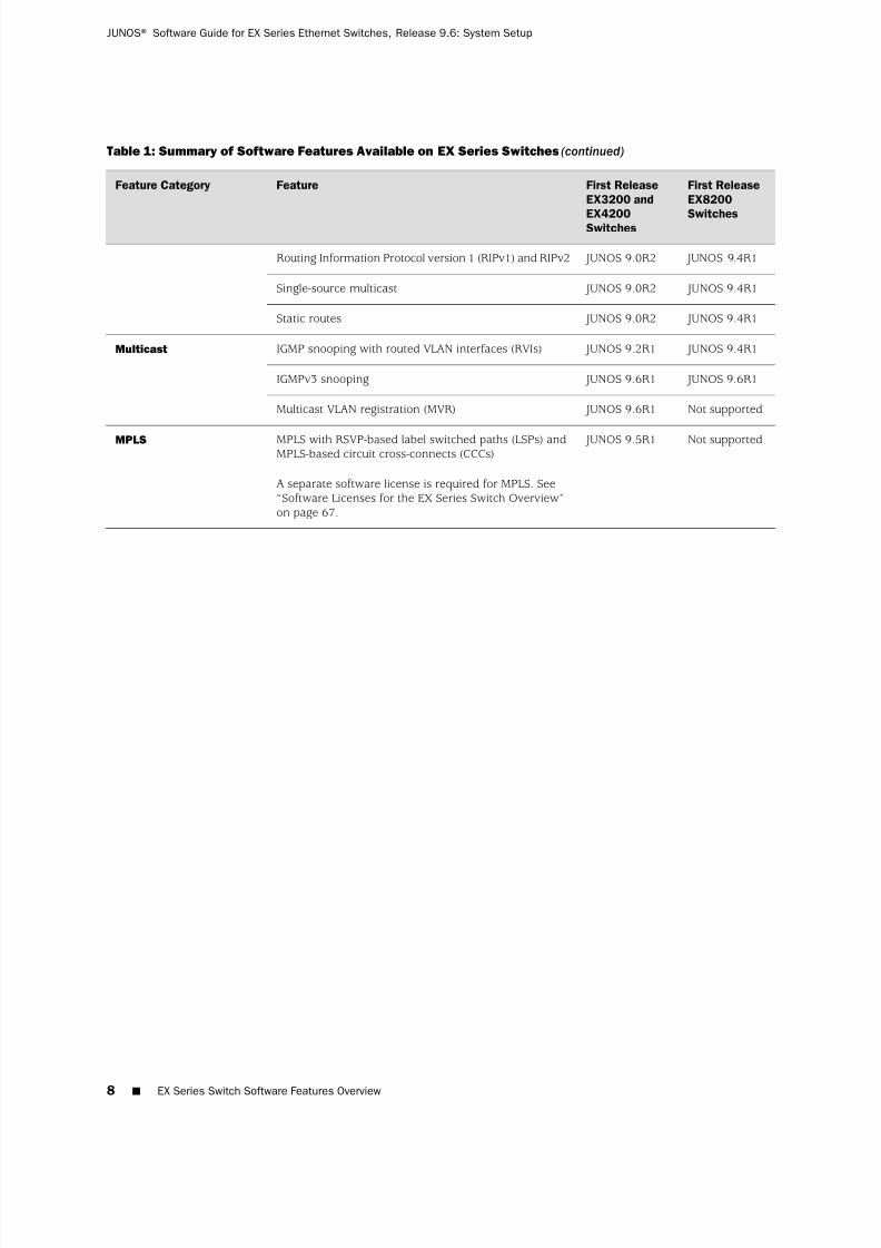
Routing Information Protocol version 1 (RIPv1) and RIPv2 JUNOS 9.4R1 JUNOS 9.0R2
JUNOS 9.4R1 JUNOS 9.0R2Single-source multicast
JUNOS 9.4R1 JUNOS 9.0R2Static routes
JUNOS 9.4R1 JUNOS 9.2R1IGMP snooping with routed VLAN interfaces (RVIs)Multicast
JUNOS 9.6R1 JUNOS 9.6R1IGMPv3 snooping
Not supported JUNOS 9.6R1Multicast VLAN registration (MVR)
Not supported JUNOS 9.5R1MPLS with RSVP-based label switched paths (LSPs) andMPLS-based circuit cross-connects (CCCs)
A separate software license is required for MPLS. See“Software Licenses for the EX Series Switch Overview”
on page 67.
MPLS
8 ■ EX Series Switch Software Features Overview
JUNOS® Software Guide for EX Series Ethernet Switches, Release 9.6: System Setup
7/23/2019 Book Software Ex Series System Setup
http://slidepdf.com/reader/full/book-software-ex-series-system-setup 25/98
Table 1: Summary of Software Features Available on EX Series Switches (continued)
First Release
EX8200
Switches
First Release
EX3200 and
EX4200Switches
FeatureFeature Category
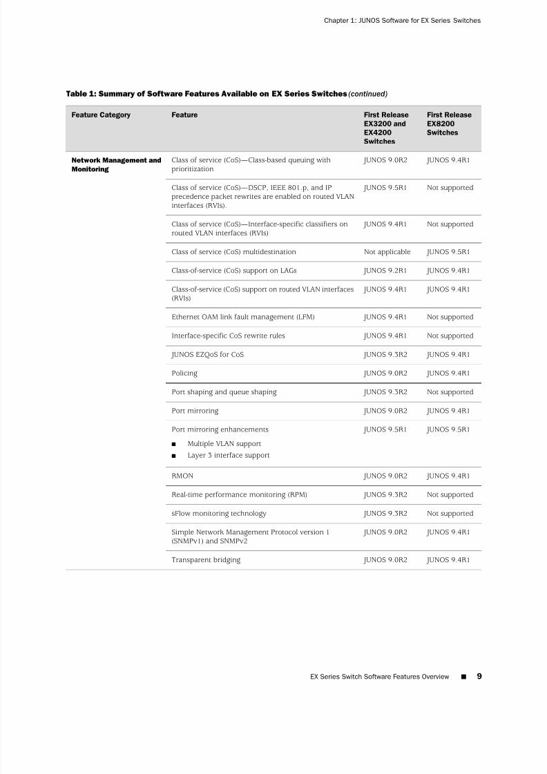
JUNOS 9.4R1 JUNOS 9.0R2Class of service (CoS)—Class-based queuing withprioritization
Network Management and
Monitoring
Not supported JUNOS 9.5R1Class of service (CoS)—DSCP, IEEE 801.p, and IPprecedence packet rewrites are enabled on routed VLANinterfaces (RVIs).
Not supported JUNOS 9.4R1Class of service (CoS)—Interface-specific classifiers onrouted VLAN interfaces (RVIs)
JUNOS 9.5R1Not applicableClass of service (CoS) multidestination
JUNOS 9.4R1 JUNOS 9.2R1Class-of-service (CoS) support on LAGs
JUNOS 9.4R1 JUNOS 9.4R1Class-of-service (CoS) support on routed VLAN interfaces(RVIs)
Not supported JUNOS 9.4R1Ethernet OAM link fault management (LFM)
Not supported JUNOS 9.4R1Interface-specific CoS rewrite rules
JUNOS 9.4R1 JUNOS 9.3R2 JUNOS EZQoS for CoS
JUNOS 9.4R1 JUNOS 9.0R2Policing
Not supported JUNOS 9.3R2Port shaping and queue shaping
JUNOS 9.4R1 JUNOS 9.0R2Port mirroring
JUNOS 9.5R1 JUNOS 9.5R1Port mirroring enhancements
■ Multiple VLAN support
■ Layer 3 interface support
JUNOS 9.4R1 JUNOS 9.0R2RMON
Not supported JUNOS 9.3R2Real-time performance monitoring (RPM)
Not supported JUNOS 9.3R2sFlow monitoring technology
JUNOS 9.4R1 JUNOS 9.0R2Simple Network Management Protocol version 1
(SNMPv1) and SNMPv2
JUNOS 9.4R1 JUNOS 9.0R2Transparent bridging
EX Series Switch Software Features Overview ■ 9
Chapter 1: JUNOS Software for EX Series Switches
7/23/2019 Book Software Ex Series System Setup
http://slidepdf.com/reader/full/book-software-ex-series-system-setup 26/98
Table 1: Summary of Software Features Available on EX Series Switches (continued)
First Release
EX8200
Switches
First Release
EX3200 and
EX4200Switches
FeatureFeature Category
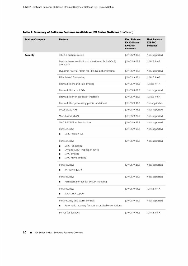
Not supported JUNOS 9.0R2802.1X authenticationSecurity
JUNOS 9.4R1 JUNOS 9.0R2Denial-of-service (DoS) and distributed DoS (DDoS)protection
Not supported JUNOS 9.0R2Dynamic firewall filters for 802.1X authentication
JUNOS 9.6R1 JUNOS 9.4R1Filter-based forwarding
JUNOS 9.4R1 JUNOS 9.0R2Firewall filters and rate limiting
Not supported JUNOS 9.0R2Firewall filters on LAGs
JUNOS 9.6R1 JUNOS 9.2R1Firewall filter on loopback interface
Not applicable JUNOS 9.3R2Firewall filter processing points, additional
Not supported JUNOS 9.3R2Local proxy ARP
Not supported JUNOS 9.2R1MAC-based VLAN
Not supported JUNOS 9.3R2MAC RADIUS authentication
Not supported JUNOS 9.3R2Port security:
■ DHCP option 82
Not supported JUNOS 9.0R2Port security:
■ DHCP snooping
■ Dynamic ARP inspection (DAI)
■ MAC limiting
■ MAC move limiting
Not supported JUNOS 9.2R1Port security:
■ IP source guard
Not supported JUNOS 9.4R1Port security:
■ Persistent storage for DHCP snooping
JUNOS 9.4R1 JUNOS 9.0R2Port security:
■ Static ARP support
Not supported JUNOS 9.6R1Port security and storm control:
■ Automatic recovery for port error disable conditions
JUNOS 9.4R1 JUNOS 9.3R2Server fail fallback
10 ■ EX Series Switch Software Features Overview
JUNOS® Software Guide for EX Series Ethernet Switches, Release 9.6: System Setup
7/23/2019 Book Software Ex Series System Setup
http://slidepdf.com/reader/full/book-software-ex-series-system-setup 27/98

7/23/2019 Book Software Ex Series System Setup
http://slidepdf.com/reader/full/book-software-ex-series-system-setup 28/98
Related Topics ■ Features in JUNOS Software for EX-series Switches, Release 9.1
■ Features in JUNOS Software for EX-series Switches, Release 9.2
■ New Features in JUNOS Software for EX-series Switches, Release 9.3
■ New Features in JUNOS Software for EX-series Switches, Release 9.4
■ New Features in JUNOS Software for EX-series Switches, Release 9.5
■ New Features in JUNOS Release 9.6 for EX Series Switches
■ EX3200 and EX4200 Switches Hardware Overview
■ EX8208 Switch Hardware Overview
■ EX8216 Switch Hardware Overview
■ High Availability Features for EX Series Switches Overview
■ Layer 3 Protocols Supported on EX Series Switches
■ Layer 3 Protocols Not Supported on EX Series Switches
Understanding Software Infrastructure and Processes
Each switch runs the Juniper Networks JUNOS Software for Juniper Networks EXSeries Ethernet Switches on its general-purpose processors. JUNOS Software includesprocesses for Internet Protocol (IP) routing and for managing interfaces, networks,and the chassis.
The JUNOS Software runs on the Routing Engine. The Routing Engine kernelcoordinates communication among the JUNOS Software processes and provides alink to the Packet Forwarding Engine.
With the J-Web interface and the command-line interface (CLI) to the JUNOS Software,you configure switching features and routing protocols and set the properties of network interfaces on your switch. After activating a software configuration, useeither the J-Web or CLI user interface to monitor the switch, manage operations, anddiagnose protocol and network connectivity problems.
■ Routing Engine and Packet Forwarding Engine on page 12
■ JUNOS Software Processes on page 13
Routing Engine and Packet Forwarding Engine
A switch has two primary software processing components:
■ Packet Forwarding Engine—Processes packets; applies filters, routing policies,and other features; and forwards packets to the next hop along the route to theirfinal destination.
■ Routing Engine—Provides three main functions:
■ Creates the packet forwarding switch fabric for the switch, providing routelookup, filtering, and switching on incoming data packets, then directingoutbound packets to the appropriate interface for transmission to the network
12 ■ Understanding Software Infrastructure and Processes
JUNOS® Software Guide for EX Series Ethernet Switches, Release 9.6: System Setup

7/23/2019 Book Software Ex Series System Setup
http://slidepdf.com/reader/full/book-software-ex-series-system-setup 29/98

7/23/2019 Book Software Ex Series System Setup
http://slidepdf.com/reader/full/book-software-ex-series-system-setup 30/98
Table 2: JUNOS Software Processes (continued)
DescriptionNameProcess
Defines how routing protocols such as RIP, OSPF, and BGP operate on the device,including selecting routes and maintaining forwarding tables.rpdRouting protocolprocess
Related Topics For more information about processes, see the JUNOS Network Operations Guideat http://www.juniper.net/techpubs/software/junos/junos90/index.html.
■
■ For more information about basic system parameters, supported protocols, andsoftware processes, see JUNOS System Basics Configuration Guide athttp://www.juniper.net/techpubs/software/junos/junos94/index.html.
JUNOS Configuration Tools
■
CLI User Interface Overview on page 14■ J-Web User Interface for EX Series Switches Overview on page 16
■ Understanding J-Web Configuration Tools on page 18
■ Understanding J-Web User Interface Sessions on page 19
CLI User Interface Overview
You can use two interfaces to monitor, configure, troubleshoot, and manage a JuniperNetworks EX Series Ethernet Switch: the J-Web graphical user interface and the
JUNOS command-line interface (CLI). Both of these user interfaces are shipped withthe switch. This topic describes the CLI. For information about the J-Web userinterface, see “ J-Web User Interface for EX Series Switches Overview” on page 16.
■ CLI Overview on page 14
■ CLI Help and Command Completion on page 15
■ CLI Command Modes on page 15
CLI Overview
JUNOS CLI is a Juniper Networks specific command shell that runs on top of aUNIX-based operating system kernel. The CLI provides command help and commandcompletion.
The CLI also provides a variety of UNIX utilities, such as Emacs-style keyboard
sequences that allow you to move around on a command line and scroll throughrecently executed commands, regular expression matching to locate and replacevalues and identifiers in a configuration, filter command output, or log file entries,store and archive router files on a UNIX-based file system, and exit from the CLIenvironment and create a UNIX C shell or Bourne shell to navigate the file system,manage switch processes, and so on.
14 ■ JUNOS Configuration Tools
JUNOS® Software Guide for EX Series Ethernet Switches, Release 9.6: System Setup
7/23/2019 Book Software Ex Series System Setup
http://slidepdf.com/reader/full/book-software-ex-series-system-setup 31/98
CLI Help and Command Completion
To access CLI Help, type a question mark (?) at any level of the hierarchy. The systemdisplays a list of the available commands or statements and a short description of each.
To complete a command, statement, or option that you have partially typed, pressthe Tab key or the Spacebar. If the partially typed letters uniquely identify a command,the complete command name appears. Otherwise, a beep indicates that you haveentered an ambiguous command and the possible completions are displayed. Thiscompletion feature also applies to other strings, such as filenames, interface names,usernames, and configuration statements.
CLI Command Modes
The CLI has two modes, operational mode and configuration mode.
In operational mode, you enter commands to monitor and troubleshoot switchhardware and software and network connectivity. Operational mode is indicated bythe > prompt—for example, user@switch>.
In configuration mode, you can define all properties of the Juniper Networks JUNOSSoftware, including interfaces, VLANs, Virtual Chassis information, routing protocols,user access, and several system hardware properties.
To enter configuration mode, enter the configure command: .
user@switch> configure
Configuration mode is indicated by the # prompt, and includes the current locationin the configuration hierarchy—for example:
[edit interfaces ge-0/0/12]user@switch#
In configuration mode, you are actually viewing and changing the candidateconfiguration file. The candidate configuration allows you to make configurationchanges without causing operational changes to the current operating configuration,called the active configuration. When you commit the changes you added to thecandidate configuration, the system updates the active configuration. Candidateconfigurations enable you to alter your configuration without causing potential damageto your current network operations.
To activate your configuration changes, enter the commit command.
To return to operational mode, go to the top of the configuration hierarchy and thenquit—for example:
[edit interfaces ge-0/0/12]user@switch# top[edit]user@switch# exit
CLI User Interface Overview ■ 15
Chapter 1: JUNOS Software for EX Series Switches

7/23/2019 Book Software Ex Series System Setup
http://slidepdf.com/reader/full/book-software-ex-series-system-setup 32/98
You can also activate your configuration changes and exit configuration mode witha single command, commit and-quit. This command succeeds only if there are nomistakes or syntax errors in the configuration.
TIP: When you commit the candidate configuration, you can require an explicitconfirmation for the commit to become permanent by using the commit confirmedcommand. This is useful for verifying that a configuration change works correctlyand does not prevent management access to the switch. After you issue the commitconfirmed command, you must issue another commit command within the definedperiod of time (10 minutes by default) or the system reverts to the previousconfiguration.
Related Topics EX Series Switch Software Features Overview on page 3■
■ JUNOS Software CLI User Guide at http://www.juniper.net/techpubs/software/junos.
J-Web User Interface for EX Series Switches Overview
You can use two interfaces to monitor, configure, troubleshoot, and manage a JuniperNetworks EX Series Ethernet Switch: the J-Web graphical user interface and the
JUNOS command-line interface (CLI). Both of these user interfaces are shipped withthe switch. This topic describes the J-Web interface. You can navigate the J-Webinterface, scroll pages, and expand and collapse elements as you do in a typical Webbrowser interface. For information about the CLI user interface, see “CLI User InterfaceOverview” on page 14.
Use Internet Explorer version 6.0 and higher, or Firefox version 2.0 and higher, toaccess the J-Web interface.
NOTE: The browser and the network must support receiving and processing HTTP1.1 GZIP compressed data.
Each page of the J-Web interface is divided into panes.
■ Top pane—Displays system identity information and links.
■ Main pane—Location where you monitor, configure, diagnose (troubleshoot),and manage (maintain) the switch by entering information in text boxes, makingselections, and clicking buttons.
■ Side pane—Displays suboptions of the Monitor, Configure, Troubleshoot, or
Maintain task currently displayed in the main pane. Click a suboption to accessit in the main pane.
The layout of the panes allows you to quickly navigate through the interface. Table3 on page 17 summarizes the elements of the J-Web interface.
The J-Web interface provides CLI tools that allow you to perform all of the tasks thatyou can perform from the JUNOS command-line interface (CLI), including a CLIViewer to view the current configuration, a CLI Editor for viewing and modifying the
16 ■ J-Web User Interface for EX Series Switches Overview
JUNOS® Software Guide for EX Series Ethernet Switches, Release 9.6: System Setup
7/23/2019 Book Software Ex Series System Setup
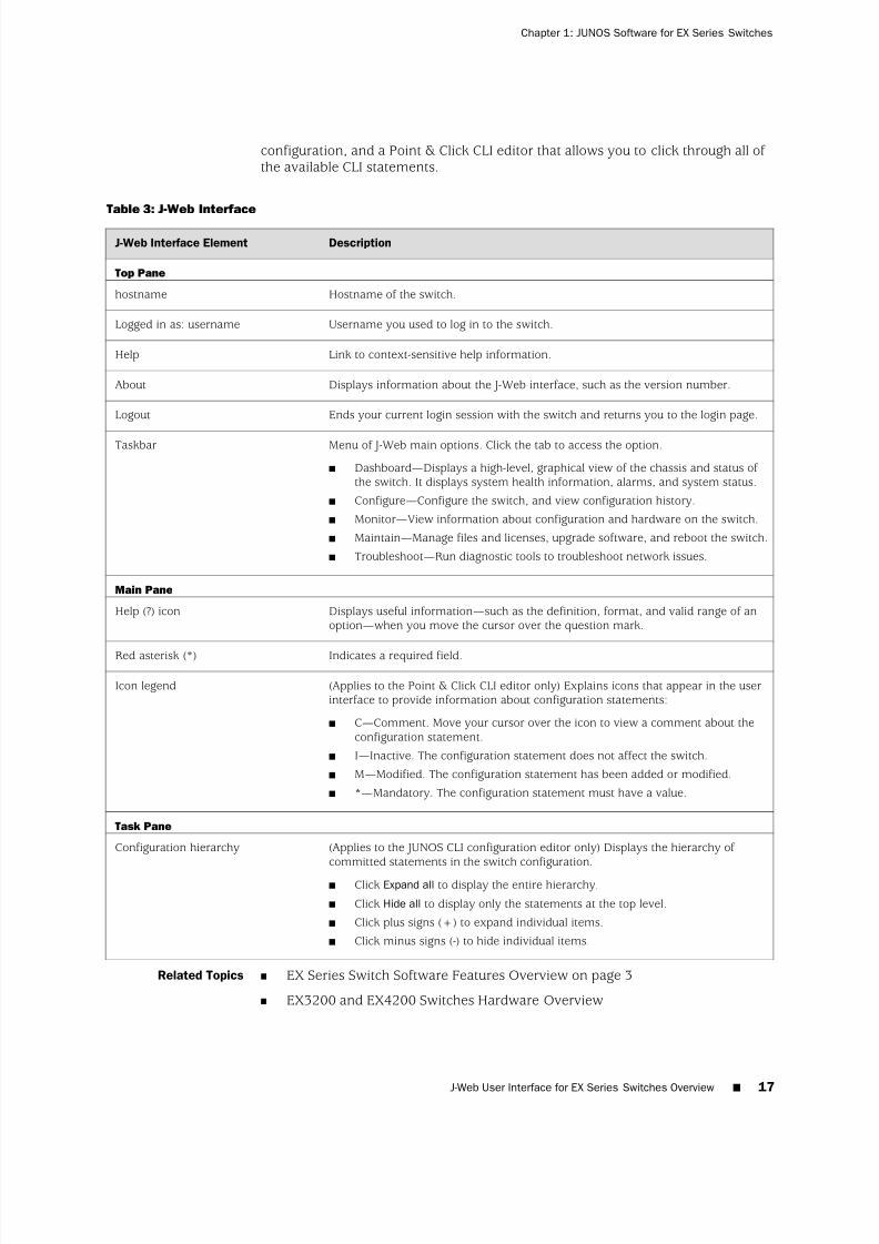
http://slidepdf.com/reader/full/book-software-ex-series-system-setup 33/98
configuration, and a Point & Click CLI editor that allows you to click through all of the available CLI statements.
Table 3: J-Web Interface
DescriptionJ-Web Interface Element
Top Pane
Hostname of the switch.hostname
Username you used to log in to the switch.Logged in as: username
Link to context-sensitive help information.Help
Displays information about the J-Web interface, such as the version number.About
Ends your current login session with the switch and returns you to the login page.Logout
Menu of J-Web main options. Click the tab to access the option.
■ Dashboard—Displays a high-level, graphical view of the chassis and status of the switch. It displays system health information, alarms, and system status.
■ Configure—Configure the switch, and view configuration history.
■ Monitor—View information about configuration and hardware on the switch.
■ Maintain—Manage files and licenses, upgrade software, and reboot the switch.
■ Troubleshoot—Run diagnostic tools to troubleshoot network issues.
Taskbar
Main Pane
Displays useful information—such as the definition, format, and valid range of anoption—when you move the cursor over the question mark.
Help (?) icon
Indicates a required field.Red asterisk (*)
(Applies to the Point & Click CLI editor only) Explains icons that appear in the userinterface to provide information about configuration statements:
■ C—Comment. Move your cursor over the icon to view a comment about theconfiguration statement.
■ I—Inactive. The configuration statement does not affect the switch.
■ M—Modified. The configuration statement has been added or modified.
■ *—Mandatory. The configuration statement must have a value.
Icon legend
Task Pane
(Applies to the JUNOS CLI configuration editor only) Displays the hierarchy of committed statements in the switch configuration.
■ Click Expand all to display the entire hierarchy.
■ Click Hide all to display only the statements at the top level.
■ Click plus signs (+) to expand individual items.
■ Click minus signs (-) to hide individual items.
Configuration hierarchy
Related Topics ■ EX Series Switch Software Features Overview on page 3
■ EX3200 and EX4200 Switches Hardware Overview
J-Web User Interface for EX Series Switches Overview ■ 17
Chapter 1: JUNOS Software for EX Series Switches
7/23/2019 Book Software Ex Series System Setup
http://slidepdf.com/reader/full/book-software-ex-series-system-setup 34/98
■ EX Series Switch Software Features Overview on page 3
■ Connecting and Configuring an EX Series Switch (J-Web Procedure) on page 57
■ CLI User Interface Overview on page 14
Understanding J-Web Configuration Tools
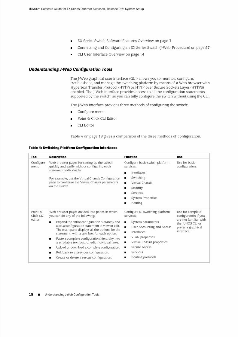
The J-Web graphical user interface (GUI) allows you to monitor, configure,troubleshoot, and manage the switching platform by means of a Web browser withHypertext Transfer Protocol (HTTP) or HTTP over Secure Sockets Layer (HTTPS)enabled. The J-Web interface provides access to all the configuration statementssupported by the switch, so you can fully configure the switch without using the CLI.
The J-Web interface provides three methods of configuring the switch:
■ Configure menu
■ Point & Click CLI Editor■ CLI Editor
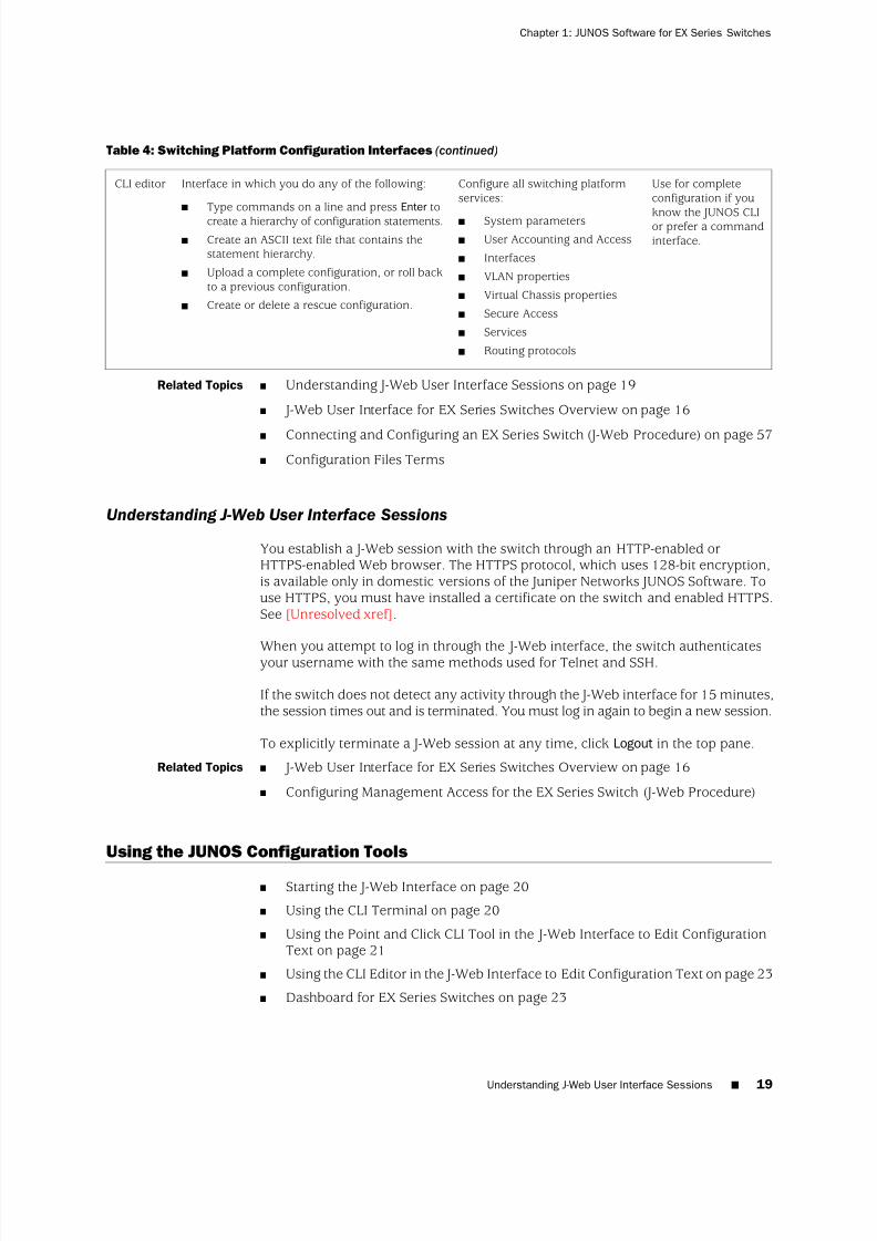
Table 4 on page 18 gives a comparison of the three methods of configuration.
Table 4: Switching Platform Configuration Interfaces
UseFunctionDescriptionTool
Use for basicconfiguration.
Configure basic switch platformservices:
■ Interfaces
■ Switching■ Virtual Chassis
■ Security
■ Services
■ System Properties
■ Routing
Web browser pages for setting up the switchquickly and easily without configuring eachstatement individually.
For example, use the Virtual Chassis Configurationpage to configure the Virtual Chassis parameterson the switch.
Configuremenu
Use for completeconfiguration if youare not familiar withthe JUNOS CLI orprefer a graphicalinterface.
Configure all switching platformservices:
■ System parameters
■ User Accounting and Access
■ Interfaces
■ VLAN properties■ Virtual Chassis properties
■ Secure Access
■ Services
■ Routing protocols
Web browser pages divided into panes in whichyou can do any of the following:
■ Expand the entire configuration hierarchy andclick a configuration statement to view or edit.The main pane displays all the options for thestatement, with a text box for each option.
■ Paste a complete configuration hierarchy intoa scrollable text box, or edit individual lines.
■ Upload or download a complete configuration.
■ Roll back to a previous configuration.
■ Create or delete a rescue configuration.
Point &Click CLIeditor
18 ■ Understanding J-Web Configuration Tools
JUNOS® Software Guide for EX Series Ethernet Switches, Release 9.6: System Setup
7/23/2019 Book Software Ex Series System Setup
http://slidepdf.com/reader/full/book-software-ex-series-system-setup 35/98
7/23/2019 Book Software Ex Series System Setup
http://slidepdf.com/reader/full/book-software-ex-series-system-setup 36/98
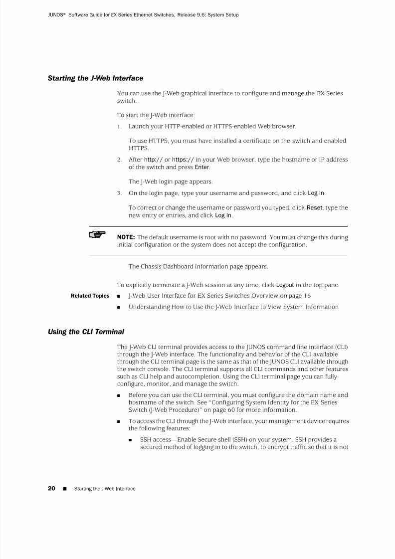
Starting the J-Web Interface
You can use the J-Web graphical interface to configure and manage the EX Seriesswitch.
To start the J-Web interface:
1. Launch your HTTP-enabled or HTTPS-enabled Web browser.
To use HTTPS, you must have installed a certificate on the switch and enabledHTTPS.
2. After http:// or https:// in your Web browser, type the hostname or IP addressof the switch and press Enter.
The J-Web login page appears.
3. On the login page, type your username and password, and click Log In.To correct or change the username or password you typed, click Reset, type thenew entry or entries, and click Log In.
NOTE: The default username is root with no password. You must change this duringinitial configuration or the system does not accept the configuration.
The Chassis Dashboard information page appears.
To explicitly terminate a J-Web session at any time, click Logout in the top pane.
Related Topics J-Web User Interface for EX Series Switches Overview on page 16■
■ Understanding How to Use the J-Web Interface to View System Information
Using the CLI Terminal
The J-Web CLI terminal provides access to the JUNOS command line interface (CLI)through the J-Web interface. The functionality and behavior of the CLI availablethrough the CLI terminal page is the same as that of the JUNOS CLI available throughthe switch console. The CLI terminal supports all CLI commands and other featuressuch as CLI help and autocompletion. Using the CLI terminal page you can fullyconfigure, monitor, and manage the switch.
■ Before you can use the CLI terminal, you must configure the domain name andhostname of the switch. See “Configuring System Identity for the EX SeriesSwitch (J-Web Procedure)” on page 60 for more information.
■ To access the CLI through the J-Web interface, your management device requiresthe following features:
■ SSH access—Enable Secure shell (SSH) on your system. SSH provides asecured method of logging in to the switch, to encrypt traffic so that it is not
20 ■ Starting the J-Web Interface
JUNOS® Software Guide for EX Series Ethernet Switches, Release 9.6: System Setup

7/23/2019 Book Software Ex Series System Setup
http://slidepdf.com/reader/full/book-software-ex-series-system-setup 37/98
intercepted. If SSH is not enabled on the system, the CLI terminal pagedisplays an error.
■ Java applet support—Make sure that your Web browser supports Java applets.
■ JRE installed on the client—Install Java Runtime Environment (JRE) version1.4 or later on your system. JRE is a software package that must be installedon a system to run Java applications. Download the latest JRE version fromthe Java Software website http://www.java.com/. Installing JRE installs Javaplug-ins, which once installed, load automatically and transparently to render
Java applets.
NOTE: The CLI terminal is supported on JRE version 1.4 and later only.
To access the CLI terminal, select Troubleshoot >CLI Terminal.
Related Topics CLI User Interface Overview on page 14■
■ Understanding J-Web Configuration Tools on page 18
Using the Point and Click CLI Tool in the J-Web Interface to Edit Configuration Text
To edit the configuration on a series of pages of clickable options that steps youthrough the hierarchy, select Configure>CLI Tools>Point&Click CLI. The side panedisplays the top level of the configured hierarchy, and the main pane displaysconfigured hierarchy options and the Icon Legend.
To expand or hide the hierarchy of all the statements in the side pane, click Expand
all or Hide all. To expand or hide an individual statement in the hierarchy, click theexpand (+) or collapse (–) icon to the left of the statement.
TIP: Only those statements included in the committed configuration are displayedin the hierarchy.
The configuration information in the main pane consists of configuration optionsthat correspond to configuration statements. Configuration options that containsubordinate statements are identified by the term Nested .
To include, edit, or delete statements in the candidate configuration, click one of thelinks described in Table 5 on page 21. Then specify configuration information bytyping in a field, selecting a value from a list, or clicking a check box (toggle).
Table 5: J-Web Edit Point & Click Configuration Links
FunctionLink
Displays fields and lists for a statement identifier, allowing you to add a new identifier to astatement.
Add new entry
Using the Point and Click CLI Tool in the J-Web Interface to Edit Configuration Text ■ 21
Chapter 1: JUNOS Software for EX Series Switches

7/23/2019 Book Software Ex Series System Setup
http://slidepdf.com/reader/full/book-software-ex-series-system-setup 38/98
Table 5: J-Web Edit Point & Click Configuration Links (continued)
FunctionLink
Displays information for a configuration option that has not been configured, allowing you toinclude a statement.Configure
Deletes the corresponding statement or identifier from the configuration. All subordinate statementsand identifiers contained within a deleted statement are also discarded.
Delete
Displays information for a configuration option that has already been configured, allowing you toedit a statement.
Edit
Displays fields and lists for an existing statement identifier, allowing you to edit the identifier.Identifier
As you navigate through the configuration, the hierarchy level is displayed at the topof the main pane. You can click a statement or identifier in the hierarchy to display
the corresponding configuration options in the main pane.
The main pane includes icons that display information about statements andidentifiers when you place your cursor over them. Table 6 on page 22 describesthese icons.
Table 6: J-Web Edit Point & Click Configuration Icons
FunctionIcon
Displays a comment about a statement.C
Indicates that a statement is inactive.I
Indicates that a statement has been added or modified but has not been committed.M
Indicates that the statement or identifier is required in the configuration.*
Provides online help information.?
After typing or selecting your configuration edits, click a button in the main pane(described in Table 7 on page 22) to apply your changes or cancel them, refresh thedisplay, or discard parts of the candidate configuration. An updated configurationdoes not take effect until you commit it.
Table 7: J-Web Edit Point & Click Configuration Buttons
FunctionButton
Updates the display with any changes to the configuration made by other users.Refresh
Verifies edits and applies them to the current configuration file running on the switch.Commit
Removes edits applied to or deletes existing statements or identifiers from the candidateconfiguration.
DiscardRelated Topics ■ CLI User Interface Overview on page 14
22 ■ Using the Point and Click CLI Tool in the J-Web Interface to Edit Configuration Text
JUNOS® Software Guide for EX Series Ethernet Switches, Release 9.6: System Setup

7/23/2019 Book Software Ex Series System Setup
http://slidepdf.com/reader/full/book-software-ex-series-system-setup 39/98
■ Understanding J-Web Configuration Tools on page 18
Using the CLI Editor in the J-Web Interface to Edit Configuration Text
Use the CLI Editor to edit configuration if you know the JUNOS CLI or prefer acommand interface.
To edit the entire configuration in text format:
CAUTION: We recommend that you use this method to edit and commit theconfiguration only if you have experience editing configurations through the CLI.
1. Select Configure>CLI Tools>CLI Editor. The main pane displays the configurationin a text editor.
2. Navigate to the hierarchy level you want to edit.
You can edit the candidate configuration using standard text editoroperations—insert lines (by using the Enter key), delete lines, and modify, copy,and paste text.
3. Click Commit to load and commit the configuration.
The switching platform checks the configuration for the correct syntax beforecommitting it.
Related Topics CLI User Interface Overview on page 14■
■ Understanding J-Web Configuration Tools on page 18
Dashboard for EX Series Switches
When you log in to the J-Web user interface, the dashboard for the EX Series switchappears. Use the dashboard to view system information.
The dashboard comprises four panels and a graphical chassis viewer. You can clickPreferences to choose which panels are to be displayed and set the refresh intervalfor chassis viewer information. Click OK to save your preference changes and returnto the dashboard or click Cancel to return to the dashboard without saving changes.
NOTE: You can drag and drop the various panels to different locations in the J-Webwindow.
This topic describes:
■ System Information Panel on page 24
■ Health Status Panel on page 24
■ Capacity Utilization Panel on page 25
Using the CLI Editor in the J-Web Interface to Edit Configuration Text ■ 23
Chapter 1: JUNOS Software for EX Series Switches
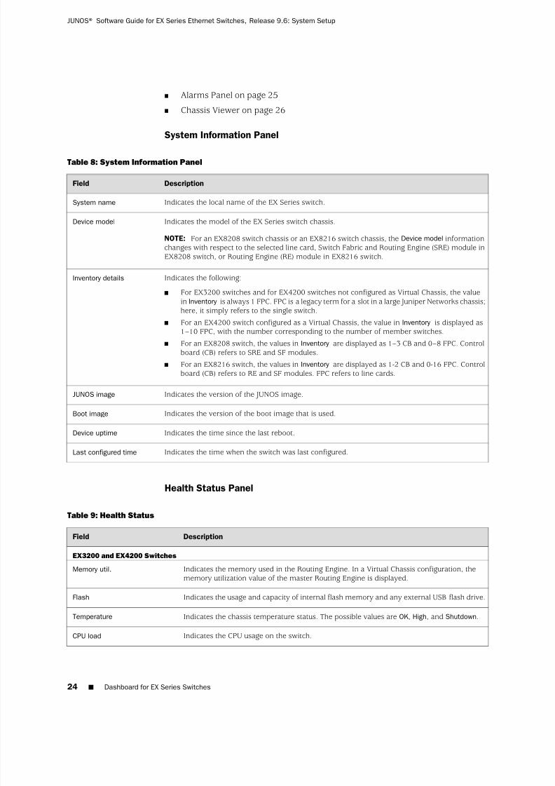
7/23/2019 Book Software Ex Series System Setup
http://slidepdf.com/reader/full/book-software-ex-series-system-setup 40/98
■ Alarms Panel on page 25
■ Chassis Viewer on page 26
System Information Panel
Table 8: System Information Panel
DescriptionField
Indicates the local name of the EX Series switch.System name
Indicates the model of the EX Series switch chassis.
NOTE: For an EX8208 switch chassis or an EX8216 switch chassis, the Device model informationchanges with respect to the selected line card, Switch Fabric and Routing Engine (SRE) module inEX8208 switch, or Routing Engine (RE) module in EX8216 switch.
Device model
Indicates the following:
■ For EX3200 switches and for EX4200 switches not configured as Virtual Chassis, the valuein Inventory is always 1 FPC. FPC is a legacy term for a slot in a large Juniper Networks chassis;here, it simply refers to the single switch.
■ For an EX4200 switch configured as a Virtual Chassis, the value in Inventory is displayed as1–10 FPC, with the number corresponding to the number of member switches.
■ For an EX8208 switch, the values in Inventory are displayed as 1–3 CB and 0–8 FPC. Controlboard (CB) refers to SRE and SF modules.
■ For an EX8216 switch, the values in Inventory are displayed as 1-2 CB and 0-16 FPC. Controlboard (CB) refers to RE and SF modules. FPC refers to line cards.
Inventory details
Indicates the version of the JUNOS image.JUNOS image
Indicates the version of the boot image that is used.Boot image
Indicates the time since the last reboot.Device uptime
Indicates the time when the switch was last configured.Last configured time
Health Status Panel
Table 9: Health Status
DescriptionField
EX3200 and EX4200 Switches
Indicates the memory used in the Routing Engine. In a Virtual Chassis configuration, thememory utilization value of the master Routing Engine is displayed.
Memory util.
Indicates the usage and capacity of internal flash memory and any external USB flash drive.Flash
Indicates the chassis temperature status. The possible values are OK , High, and Shutdown.Temperature
Indicates the CPU usage on the switch.CPU load
24 ■ Dashboard for EX Series Switches
JUNOS® Software Guide for EX Series Ethernet Switches, Release 9.6: System Setup

7/23/2019 Book Software Ex Series System Setup
http://slidepdf.com/reader/full/book-software-ex-series-system-setup 41/98

7/23/2019 Book Software Ex Series System Setup
http://slidepdf.com/reader/full/book-software-ex-series-system-setup 42/98

7/23/2019 Book Software Ex Series System Setup
http://slidepdf.com/reader/full/book-software-ex-series-system-setup 43/98
Table 11: Chassis Viewer for EX3200 and EX4200 Switches (continued)
DescriptionField
Hover the mouse pointer over the power supply icon to display Name, Status, and Descriptioninformation.Power supply
Rear View of the EX4200 Switch
Hover the mouse pointer over the fan tray icon to display Name, Status, and Descriptioninformation. For a Virtual Chassis, the status of the fans of the selected member switch is displayed.
Fan tray
Displayed only when switches are configured as a Virtual Chassis. The colors listed below denotethe Virtual Chassis port (VCP) status:
■ Green—VCP is up and operational.
■ Yellow—VCP is up but is nonoperational.
■ Gray—VCP is down and nonoperational.
Virtual Chassis port
Indicates the USB port for the switch.
NOTE: We recommend you use USB flash drives purchased from Juniper Networks for your EXSeries switch.
USB port
The management port is used to connect the switch to a management device for out-of-bandmanagement.
Management port
The console port is used to connect the switch to a management console or to a console server.(You might do this for initial switch configuration.)
Console port
Hover the mouse pointer over the power supply icons to display Name, Status, and Descriptioninformation.
Power supplies
Table 12: Chassis Viewer for EX8208 Switches
DescriptionField
Front View
Dashboard for EX Series Switches ■ 27
Chapter 1: JUNOS Software for EX Series Switches

7/23/2019 Book Software Ex Series System Setup
http://slidepdf.com/reader/full/book-software-ex-series-system-setup 44/98
Table 12: Chassis Viewer for EX8208 Switches (continued)
DescriptionField
In the image, click any line card, SRE module, or SF module to view the front view of the selectedcomponent. The colors listed below denote the interface status:
■ Green—Interface is up and operational.
■ Yellow—Interface is up but is nonoperational.
■ Gray—Interface is down and nonoperational.
Hover the mouse pointer over the port to view more information.
You can view status for the following ports on the SRE module:
■ USB port—Indicates the USB port for the switch.
NOTE: We recommend you use USB flash drives purchased from Juniper Networks for your EX Seriesswitch.
■ Auxiliary port—This port is not enabled on the switch. It is reserved for future use.
■ Management port—The management port is used to connect the switch to a management devicefor out-of-band management.
■ Console port—The console port is used to connect the switch to a management console or to aconsole server. (You might do this for initial switch configuration.)
Because the SF module has no ports, no status information is displayed.
Interface status
Slots on the switch are labeled, from the top of the switch down:
■ 0–3 (line cards)
■ SRE0, SF, SRE1 (SRE and SF modules)
■ 4–7 (line cards)
Slot numbers
The active slots contain a gray temperature icon. Hover the mouse pointer over the icon to displaytemperature information for the slot.
Temperature
Hover the mouse pointer over the fan tray icon to display Name, Status, and Description information.Fan status
Hover the mouse pointer over the power supply icons to display Name, Status, and Descriptioninformation.
Power supplies
LCD panel configured for the LEDs on the ports. Hover the mouse pointer over the icon to view thecurrent character display.
LCD panel
The EX8208 switch does not have any components on the rear of the chassis.Rear View
Table 13: Chassis Viewer for EX8216 Switches
DescriptionField
Front View
28 ■ Dashboard for EX Series Switches
JUNOS® Software Guide for EX Series Ethernet Switches, Release 9.6: System Setup

7/23/2019 Book Software Ex Series System Setup
http://slidepdf.com/reader/full/book-software-ex-series-system-setup 45/98
Table 13: Chassis Viewer for EX8216 Switches (continued)
DescriptionField
In the image, click any line card or RE module to view the front view of the selected component.The colors listed below denote the interface status:
■ Green—Interface is up and operational.
■ Yellow—Interface is up but is nonoperational.
■ Gray—Interface is down and nonoperational.
Hover the mouse pointer over the port to view more information.
You can view status for the following ports on the RE module:
■ USB port—Indicates the USB port for the switch.
NOTE: We recommend you use USB flash drives purchased from Juniper Networks for your EXSeries switch.
■ Auxiliary port—This port is not enabled on the switch. It is reserved for future use.
■ Management port—The management port is used to connect the switch to a managementdevice for out-of-band management.
■ Console port—The console port is used to connect the switch to a management console or toa console server. (You might do this for initial switch configuration.)
Because the SF module has no ports, no status information is displayed.
Interface status
Slots on the switch are labeled, from the top of the switch down:
■ RE0 (RE module)
■ RE1 (RE module)
■ 0–15 (line cards)
Slot numbers
The active slots contain a gray temperature icon. Hover the mouse pointer over the icon to displaytemperature information for the slot.
Temperature
Hover the mouse pointer over the fan tray icon to display consolidated fan information.Fan status
Hover the mouse pointer over the power supply icons to display Name, Status, and Descriptioninformation.
Power supplies
LCD panel configured for the LEDs on the ports. Hover the mouse pointer over the icon to view thecurrent character display.
LCD panel
Rear View
Hover the mouse pointer over the SF module icons in their respective slots to display information.
Slots are numbered SF7–
SF0, from left to right.
SF Modules
Related Topics ■ J-Web User Interface for EX Series Switches Overview on page 16
■ Checking Active Alarms with the J-Web Interface
■ EX3200 and EX4200 Switches Hardware Overview
■ EX8208 Switch Hardware Overview
■ EX8216 Switch Hardware Overview
Dashboard for EX Series Switches ■ 29
Chapter 1: JUNOS Software for EX Series Switches

7/23/2019 Book Software Ex Series System Setup
http://slidepdf.com/reader/full/book-software-ex-series-system-setup 46/98
30 ■ Dashboard for EX Series Switches
JUNOS® Software Guide for EX Series Ethernet Switches, Release 9.6: System Setup

7/23/2019 Book Software Ex Series System Setup
http://slidepdf.com/reader/full/book-software-ex-series-system-setup 47/98
Chapter 2
Software Installation
■ JUNOS Software Installation on page 31
■ Installing JUNOS Software on EX Series Switches on page 36
■ Verifying JUNOS Software Installation on page 49
■ Troubleshooting JUNOS Software Installation on page 50
JUNOS Software Installation
■ Understanding Software Installation on EX Series Switches on page 31
■ JUNOS Software Package Names on page 33
■ Understanding Autoinstallation of Configuration Files on EX SeriesSwitches on page 34
Understanding Software Installation on EX Series Switches
A Juniper Networks EX Series Ethernet Switch is delivered with Juniper Networks
JUNOS Software preinstalled. As new features and software fixes become available,you must upgrade your software to use them. You can also downgrade JUNOSSoftware to a previous release.
This topic covers:
■ Overview of the Software Installation Process on page 31
■ Software Package Security on page 32
■ Installing Software on a Virtual Chassis on page 32
■ Installing Software on EX8200 Switches with Redundant RoutingEngines on page 32
■ Installing Software Using Automatic Software Download on page 32
■ Troubleshooting Software Installation on page 33
Overview of the Software Installation Process
An EX Series switch is delivered with JUNOS Software preinstalled. When you connectpower to the switch, it starts (boots) up from the installed software.
You upgrade JUNOS Software on an EX Series switch by copying a software packageto your switch or another system on your local network, then use either the J-Web
JUNOS Software Installation ■ 31

7/23/2019 Book Software Ex Series System Setup
http://slidepdf.com/reader/full/book-software-ex-series-system-setup 48/98
interface or the CLI to install the new software package on the switch. Finally, youreboot the switch; it boots from the upgraded software. After a successful upgrade,you should back up the new current configuration to a secondary device.
During a successful upgrade, the upgrade package removes all files from /var/tmpand completely reinstalls the existing software. It retains configuration files, andsimilar information, such as secure shell and host keys, from the previous version.The previous software package is preserved in a separate disk partition, and you canmanually revert back to it if necessary. If the software installation fails for any reason,such as loss of power during the installation process, the system returns to theoriginally active installation when you reboot.
Software Package Security
All JUNOS Software is delivered in signed packages that contain digital signatures toensure official Juniper Networks software. For more information about signed software
packages, see the JUNOS Software Installation and Upgrade Guide athttp://www.juniper.net/techpubs/software/junos/junos96/index.html.
Installing Software on a Virtual Chassis
You can connect individual Juniper Networks EX4200 Ethernet Switches together toform one unit and manage the unit as a single chassis, called a Virtual Chassis. TheVirtual Chassis operates as a single network entity composed of members. Eachmember of a Virtual Chassis runs a JUNOS Software package.
For ease of management, the Virtual Chassis provides flexible methods to upgradesoftware releases. You can deploy a new software release to all members of a VirtualChassis or to only a particular member.
Installing Software on EX8200 Switches with Redundant Routing Engines
To install software on a Juniper Networks EX8200 Ethernet Switch that has twoRouting Engines with minimal network disruption, you perform a JUNOS Softwareinstallation on each Routing Engine separately, starting with the backup. See “InstallingSoftware on an EX8200 Switch with Redundant Routing Engines (CLI Procedure)”on page 38.
Installing Software Using Automatic Software Download
The automatic software download feature uses the DHCP message exchange processto download and install software packages. Users can define a path to a software
package on the DHCP server and then the DHCP server communicates this path toEX Series switches acting as DHCP clients as part of the DHCP message exchangeprocess. The DHCP clients that have been configured for automatic software downloadreceive these messages and, when the software package name in the DHCP servermessage is different from that of the software package that booted the DHCP clientswitch, download and install the software package. See “Upgrading Software UsingAutomatic Software Download on EX Series Switches” on page 48.
32 ■ Understanding Software Installation on EX Series Switches
JUNOS® Software Guide for EX Series Ethernet Switches, Release 9.6: System Setup
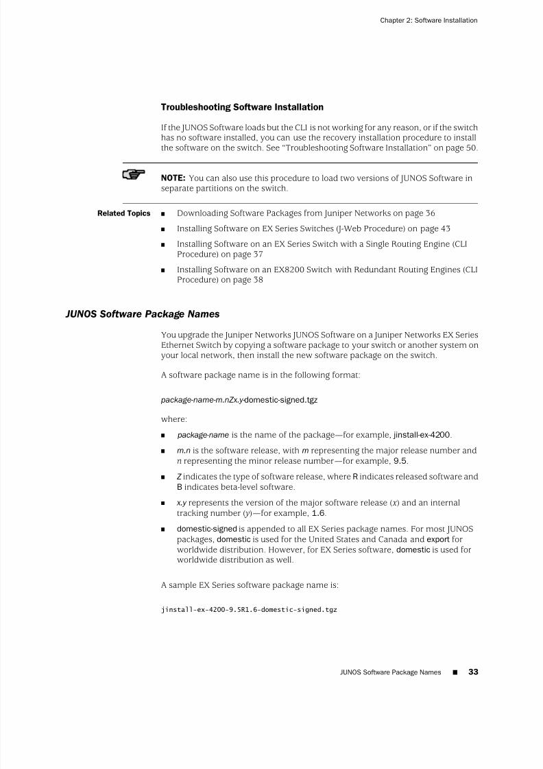
7/23/2019 Book Software Ex Series System Setup
http://slidepdf.com/reader/full/book-software-ex-series-system-setup 49/98
Troubleshooting Software Installation
If the JUNOS Software loads but the CLI is not working for any reason, or if the switchhas no software installed, you can use the recovery installation procedure to installthe software on the switch. See “Troubleshooting Software Installation” on page 50.
NOTE: You can also use this procedure to load two versions of JUNOS Software inseparate partitions on the switch.
Related Topics ■ Downloading Software Packages from Juniper Networks on page 36
■ Installing Software on EX Series Switches (J-Web Procedure) on page 43
■ Installing Software on an EX Series Switch with a Single Routing Engine (CLIProcedure) on page 37
■ Installing Software on an EX8200 Switch with Redundant Routing Engines (CLIProcedure) on page 38
JUNOS Software Package Names
You upgrade the Juniper Networks JUNOS Software on a Juniper Networks EX SeriesEthernet Switch by copying a software package to your switch or another system onyour local network, then install the new software package on the switch.
A software package name is in the following format:
package-name-m.nZx.y- domestic-signed.tgz
where:
■ package-name is the name of the package—for example, jinstall-ex-4200.
■ m.n is the software release, with m representing the major release number andn representing the minor release number—for example, 9.5.
■ Z indicates the type of software release, where R indicates released software andB indicates beta-level software.
■ x.y represents the version of the major software release (x) and an internaltracking number ( y)—for example, 1.6.
■ domestic-signed is appended to all EX Series package names. For most JUNOS
packages, domestic is used for the United States and Canada and export forworldwide distribution. However, for EX Series software, domestic is used forworldwide distribution as well.
A sample EX Series software package name is:
jinstall-ex-4200-9.5R1.6-domestic-signed.tgz
JUNOS Software Package Names ■ 33
Chapter 2: Software Installation
7/23/2019 Book Software Ex Series System Setup
http://slidepdf.com/reader/full/book-software-ex-series-system-setup 50/98

7/23/2019 Book Software Ex Series System Setup
http://slidepdf.com/reader/full/book-software-ex-series-system-setup 51/98
■ switch.conf —Default configuration file for autoinstallation with a minimumconfiguration sufficient for you to telnet to the device and configure it manually.
■ hostname.conf —Host-specific configuration file for autoinstallation on a devicethat contains all the configuration information necessary for the switch. In thefilename, hostname is replaced with the hostname assigned to the switch.
If the server with the autoinstallation configuration file is not on the same LANsegment as the new device, or if a specific device is required by the network, youmust configure an intermediate device directly attached to the new switch, throughwhich the new switch can send TFTP, boot protocol (BOOTP), and Domain NameSystem (DNS) requests. In this case, you specify the IP address of the intermediatedevice as the location to receive TFTP requests for autoinstallation.
Typical Autoinstallation Process on a New Switch
When an EX Series switch is powered on for the first time, it performs the following
autoinstallation tasks:1. The new switch sends out DHCP or BOOTP requests on each connected interface
simultaneously to obtain an IP address.
If a DHCP server responds to these requests, it provides the switch with someor all of the following information:
■ An IP address and subnet mask for the autoinstallation interface.
■ The location of the (typically) TFTP server, Hypertext Transfer Protocol(HTTP) server, or FTP server on which the configuration file is stored.
■ The name of the configuration file to be requested from the TFTP server.
■ The IP address or hostname of the TFTP server.
If the DHCP server provides the server’s hostname, a DNS server must beavailable on the network to resolve the name to an IP address.
■ The IP address of an intermediate device if the configuration server is on adifferent LAN segment from the new switch.
2. After the new switch acquires an IP address, the autoinstallation process on theswitch attempts to download a configuration file in the following ways:
a. If the DHCP server specifies the host-specific configuration file hostname.conf ,the switch uses that filename in the TFTP server request. The autoinstallationprocess on the new switch makes three unicast TFTP requests for
hostname.conf . If these attempts fail, the switch broadcasts three requeststo any available TFTP server for the file.
b. If the new switch does not locate a hostname.conf file, the autoinstallationprocess sends three unicast TFTP requests for a network.conf file that containsthe switch’s hostname-to-IP-address mapping information. If these attemptsfail, the switch broadcasts three requests to any available TFTP server forthe file.
Understanding Autoinstallation of Configuration Files on EX Series Switches ■ 35
Chapter 2: Software Installation
7/23/2019 Book Software Ex Series System Setup
http://slidepdf.com/reader/full/book-software-ex-series-system-setup 52/98
c. If the switch fails to find a network.conf file that contains a hostname entryfor the switch, the autoinstallation process sends out a DNS request andattempts to resolve the new switch's IP address to a hostname.
d. If the new switch determines its hostname, it sends a TFTP request for thehostname.conf file.
e. If the new switch is unable to map its IP address to a hostname, it sendsTFTP requests for the default configuration file switch.conf . The TFTP requestprocedure is the same as for the network.conf file.
3. After the new switch locates a configuration file on a TFTP server, theautoinstallation process downloads the file, installs the file on the switch, andcommits the configuration.
Related Topics ■ Configuring Autoinstallation of Configuration Files (CLI Procedure) on page 46
■ Connecting and Configuring an EX Series Switch (CLI Procedure) on page 55
■ Connecting and Configuring an EX Series Switch (J-Web Procedure) on page 57■ Configuration Files Terms
Installing JUNOS Software on EX Series Switches
■ Downloading Software Packages from Juniper Networks on page 36
■ Installing Software on an EX Series Switch with a Single Routing Engine (CLIProcedure) on page 37
■ Installing Software on an EX8200 Switch with Redundant Routing Engines (CLIProcedure) on page 38
■ Installing Software on EX Series Switches (J-Web Procedure) on page 43
■ Booting an EX Series Switch Using a Software Package Stored on a USB FlashDrive on page 45
■ Configuring Autoinstallation of Configuration Files (CLI Procedure) on page 46
■ Upgrading Software Using Automatic Software Download on EX SeriesSwitches on page 48
Downloading Software Packages from Juniper Networks
You can download the JUNOS Software packages from the Juniper Networks website
to upgrade software on your EX Series switch.
Before you begin to download software upgrades, ensure that you have a JuniperNetworks Web account and a valid support contract. To obtain an account, completethe registration form at the Juniper Networks website:https://www.juniper.net/registration/Register.jsp.
To download software upgrades from Juniper Networks:
36 ■ Installing JUNOS Software on EX Series Switches
JUNOS® Software Guide for EX Series Ethernet Switches, Release 9.6: System Setup

7/23/2019 Book Software Ex Series System Setup
http://slidepdf.com/reader/full/book-software-ex-series-system-setup 53/98
1. Using a Web browser, follow the links to the download URL on the JuniperNetworks webpage. For EX Series, there are not separate software packages forCanada the U.S. and other locations. Therefore, select Canada and U.S. Versionregardless of your location:
■ https://www.juniper.net/support/csc/swdist-domestic/
2. Log in to the Juniper Networks authentication system using the username(generally your e-mail address) and password supplied by Juniper Networksrepresentatives.
3. Using the J-Web interface or the CLI, select the appropriate software package foryour application. See “ JUNOS Software Package Names” on page 33.
4. Download the software to a local host or to an internal software distribution site.
Related Topics Installing Software on EX Series Switches (J-Web Procedure) on page 43■
■ Installing Software on an EX Series Switch with a Single Routing Engine (CLIProcedure) on page 37
■ Understanding Software Installation on EX Series Switches on page 31
Installing Software on an EX Series Switch with a Single Routing Engine (CLI Procedure)
You can use this procedure to upgrade the JUNOS Software on an EX Series switchwith a single Routing Engine, including an individual member of a Virtual Chassis orall members of a Virtual Chassis, or an EX8200 switch using a single Routing Engine.To upgrade software on an EX8200 switch running two Routing Engines, see“Installing Software on an EX8200 Switch with Redundant Routing Engines (CLIProcedure)” on page 38.
To install software upgrades on an EX Series switch with a single Routing Engineusing the CLI:
1. Download the software package as described in “Downloading Software Packagesfrom Juniper Networks” on page 36.
2. (Optional) Back up the current software configuration to a second storage option.See the JUNOS Software Installation and Upgrade Guide athttp://www.juniper.net/techpubs/software/junos/junos95/index.html for instructions onperforming this task.
3. (Optional) Copy the software package to the switch. We recommend that youuse FTP to copy the file to the /var/tmp directory.
This step is optional because the JUNOS Software can also be upgraded whenthe software image is stored at a remote location. These instructions describethe software upgrade process for both scenarios.
4. Install the new package on the switch:
Installing Software on an EX Series Switch with a Single Routing Engine (CLI Procedure) ■ 37
Chapter 2: Software Installation

7/23/2019 Book Software Ex Series System Setup
http://slidepdf.com/reader/full/book-software-ex-series-system-setup 54/98
NOTE: A reboot, which will occur as part of the execution of the following command,is required to complete the software upgrade. If you want to reboot the switch at alater time, do not use the reboot option at this point of the procedure and enter the
request system reboot command at a later time to reboot the switch.
user@switch> request system software add source reboot
Replace source with one of the following paths:
■ For a software package that is installed from a local directory on theswitch— /pathname /package-name-m.nZx-distribution.tgz.
■ For a software package that is downloaded and installed from a remotelocation:
■ ftp://hostname /pathname /package-name-m.nZx-distribution.tgz
■ http://hostname /pathname /package-name-m.nZx-distribution.tgz
where package-name-m.nZx-distribution.tgz is, for example, jinstall-ex-4200-9.4R1.8-domestic-signed.tgz.
Include the optional member option to install the software package on only onemember of a Virtual Chassis:
user@switch> request system software add source member member-id reboot
Other members of the Virtual Chassis are not affected. To install the softwareon all members of the Virtual Chassis, do not include the member option.
5. After the reboot has completed, log in and verify that the new version of thesoftware is properly installed:
user@switch> show version
Related Topics ■ Installing Software on EX Series Switches (J-Web Procedure) on page 43
■ Troubleshooting Software Installation on page 50
■ JUNOS Software Package Names on page 33
■ See the JUNOS Software System Basics and Services Command Reference athttp://www.juniper.net/techpubs/software/junos/junos95/index.html for details aboutthe request system software add command.
■
Understanding Software Installation on EX Series Switches on page 31
Installing Software on an EX8200 Switch with Redundant Routing Engines (CLI Procedure)
For an EX8200 switch with redundant Routing Engines, you can minimize disruptingnetwork operation during a JUNOS Software upgrade by upgrading the RoutingEngines separately, starting with the backup Routing Engine.
38 ■ Installing Software on an EX8200 Switch with Redundant Routing Engines (CLI Procedure)
JUNOS® Software Guide for EX Series Ethernet Switches, Release 9.6: System Setup

7/23/2019 Book Software Ex Series System Setup
http://slidepdf.com/reader/full/book-software-ex-series-system-setup 55/98
To upgrade the software package on an EX8200 switch with one installed RoutingEngine, see “Installing Software on an EX Series Switch with a Single Routing Engine(CLI Procedure)” on page 37.
Install the new JUNOS Software release on the backup Routing Engine while keepingthe currently running software version on the master Routing Engine. After makingsure that the new software version is running correctly on the backup Routing Engine,switch device control to the backup Routing Engine. Finally, install the new softwareon the new backup Routing Engine.
To upgrade the JUNOS Software on the switch, perform the following tasks:
1. Preparing the Switch for the Software Installation on page 39
2. Installing Software on the Backup Routing Engine on page 40
3. Installing Software on the Default Master Routing Engine on page 41
4. Returning Routing Control to the Default Master Routing Engine(Optional) on page 42
Preparing the Switch for the Software Installation
Perform the following steps before installing the software:
1. Log in to the master Routing Engine’s console.
For information on logging in to the Routing Engine through the console port,see “Connecting and Configuring an EX Series Switch (CLI Procedure)” on page55.
2. Enter the JUNOS Software CLI configuration mode:
a. Start the CLI from the shell prompt:
user@switch:RE% cli
You will see:
{master}user@switch>
b. Enter configuration mode:
user@switch> configure
You will see:
{master}[[edit]user@switch#
3. Disable GRES (graceful Routing Engine switchover):
[edit]user@switch# deactivate chassis redundancy graceful-switchover
4. Save the configuration change on both Routing Engines:
Preparing the Switch for the Software Installation ■ 39
Chapter 2: Software Installation

7/23/2019 Book Software Ex Series System Setup
http://slidepdf.com/reader/full/book-software-ex-series-system-setup 56/98
[edit]user@switch# commit synchronize
NOTE: To ensure the most recent configuration changes are committed before thesoftware upgrade, perform this step even if GRES was previously disabled.
5. Exit out of the CLI configuration mode:
[edit]user@switch# exit
6. (Optional) Back up the current software configuration to a second storage option.See the JUNOS Software Installation and Upgrade Guide athttp://www.juniper.net/techpubs/software/junos/junos95/index.html for instructions onperforming this task.
Installing Software on the Backup Routing Engine
Once the EX8200 switch is ready, you first install the software on the backup RoutingEngine. This enables the master Routing Engine to continue operations, minimizingthe disruption to your network.
1. Download the software by following the procedures in “Downloading SoftwarePackages from Juniper Networks” on page 36.
2. Copy the software package to the switch. We recommend that you use FTP tocopy the file to the /var/tmp directory.
3. Log in to the backup Routing Engine’s console.
4. Install the new software package:
user@switch> request system software add validate
/var/tmp/ package-name-m.nZx-distribution.tgz
where package-name-m.nZx-distribution.tgz is, for example, jinstall-ex-8200–9.5R1.5–domestic-signed.tgz.
For more information on the request system software add command, see the JUNOS Software System Basics and Services Command Reference athttp://www.juniper.net/techpubs/software/junos/junos95/index.html.
NOTE: To abort the installation, do not reboot your device; instead, finish theinstallation and then issue the request system software delete package-name-m.nZx-distribution.tgz command, where package-name-m.nZx-distribution.tgz is, for example, jinstall-ex-4200–9.4R1.5–domestic-signed.tgz. This is your last chance to stop theinstallation.
40 ■ Installing Software on the Backup Routing Engine
JUNOS® Software Guide for EX Series Ethernet Switches, Release 9.6: System Setup

7/23/2019 Book Software Ex Series System Setup
http://slidepdf.com/reader/full/book-software-ex-series-system-setup 57/98
5. Reboot to start the new software:
user@switch> request system reboot
Reboot the system? [yes, no] (no) yes
NOTE: You must reboot the switch to load the new installation of the JUNOS Software.
6. After the reboot has completed, log in and verify the new version of the softwareis properly installed:
user@switch> show version
Installing Software on the Default Master Routing Engine
To switch device control to the backup Routing Engine and then upgrade or
downgrade the master Routing Engine software:1. Log in to the master Routing Engine console port.
2. Transfer device control to the backup Routing Engine:
user@switch> request chassis routing-engine master switch
NOTE: Because GRES is disabled, this switchover causes all line cards in the switchto reload. All network traffic passing through these line cards is lost during the linecard reloads.
3. Verify that the default backup Routing Engine (shown as slot 1 in the command
output) is now the master Routing Engine:
user@switch> show chassis routing-engine
You will see:
Routing Engine status: Slot 0: Current state Backup Election priority Master (default)Routing Engine status: Slot 1: Current state Master Election priority Backup (default)
4. Install the new software package using the request system software add command:
user@switch> request system software add validate
/var/tmp/jinstall-ex-8200-9.5R1.5-domestic-signed.tgz
5. Reboot the Routing Engine:
user@switch> request system reboot
Reboot the system? [yes, no] (no) yes
Installing Software on the Default Master Routing Engine ■ 41
Chapter 2: Software Installation

7/23/2019 Book Software Ex Series System Setup
http://slidepdf.com/reader/full/book-software-ex-series-system-setup 58/98
When the reboot completes, the prompt will reappear. Wait for this prompt toreappear before proceeding to the next step.
6. Log in to the default backup Routing Engine (slot 1) through the console port.
7. Re-enable GRES:
[edit]user@switch# activate chassis redundancy graceful-switchover
Re-enabling GRES allows any future Routing Engine switchovers to occur withoutthe loss of any network traffic.
8. Enter the commit synchronize command to save the configuration change:
[edit]user@switch# commit synchronize
9. Log in and verify the version of the software installed.
If you want to return routing control to the Routing Engine that was the masterRouting Engine at the beginning of the procedure (the default master RoutingEngine), perform the next task.
Returning Routing Control to the Default Master Routing Engine (Optional)
The switch can maintain normal operations with the Routing Engine in slot 1 actingas the master Routing Engine after the software upgrade, so only perform this taskif you want to return routing control to the default master Routing Engine in slot 0.
1. Transfer routing control back to the default master Routing Engine:
user@switch> request chassis routing-engine master switch
2. Verify that the default master Routing Engine (slot 0) is indeed the master RoutingEngine:
user@switch> show chassis routing-engine
You will see:
Routing Engine status: Slot 0: Current state Master Election priority Master (default)Routing Engine status:
Slot 1: Current state Backup Election priority Backup (default)
Related Topics ■ Installing Software on EX Series Switches (J-Web Procedure) on page 43
■ Troubleshooting Software Installation on page 50
■ JUNOS Software Package Names on page 33
42 ■ Returning Routing Control to the Default Master Routing Engine (Optional)
JUNOS® Software Guide for EX Series Ethernet Switches, Release 9.6: System Setup
7/23/2019 Book Software Ex Series System Setup
http://slidepdf.com/reader/full/book-software-ex-series-system-setup 59/98
■ Understanding Software Installation on EX Series Switches on page 31
■ Understanding EX8208 Switch Component and Functionality Redundancy
Installing Software on EX Series Switches (J-Web Procedure)
You can upgrade software packages on a single fixed-configuration switch, on anindividual member of a Virtual Chassis, or for all members of a Virtual Chassis.
You can use the J-Web interface to install software upgrades from a server using FTPor HTTP, or by copying the file to the EX Series switch.
This topic describes:
1. Installing Software Upgrades from a Server on page 43
2. Installing Software Upgrades by Uploading Files on page 44
Installing Software Upgrades from a Server
To install software upgrades from a remote server by using FTP or HTTP:
1. Download the software package as described in “Downloading Software Packagesfrom Juniper Networks” on page 36.
2. Log in to the Juniper Networks authentication system using the username(generally your e-mail address) and password supplied by Juniper Networksrepresentatives.
3. In the J-Web interface, select Maintain>Software>Install Package.
4. On the Install Remote page, enter information into the fields described in Table
14 on page 43.5. Click Fetch and Install Package. The software is activated after the switch has
rebooted.
Table 14: Install Remote Summary
Your ActionFunctionField
Type the full address of the software packagelocation on the FTP or HTTP server—one of thefollowing:
ftp://hostname /pathname /package-name
http://hostname /pathname /package-name
Specifies the FTP or HTTP server, file path, andsoftware package name.
Package Location(required)
Type the username.Specifies the username, if the server requiresone.
User
Type the password.Specifies the password, if the server requiresone.
Password
Installing Software on EX Series Switches (J-Web Procedure) ■ 43
Chapter 2: Software Installation
7/23/2019 Book Software Ex Series System Setup
http://slidepdf.com/reader/full/book-software-ex-series-system-setup 60/98
Table 14: Install Remote Summary (continued)
Your ActionFunctionField
Check the box if you want the switching platformto reboot automatically when the upgrade iscomplete.
If this box is checked, the switching platform isautomatically rebooted when the upgrade iscomplete.
Reboot If Required
Installing Software Upgrades by Uploading Files
To install software upgrades by uploading files:
1. Download the software package.
2. In the J-Web interface, select Maintain>Software>Upload Package.
3. On the Upload Package page, enter information into the fields described in Table
15 on page 44.
4. Click Upload Package. The software is activated after the switching platform hasrebooted.
Table 15: Upload Package Summary
Your ActionFunctionField
Type the location of the software package, or clickBrowse to navigate to the location.
Specifies the location of the softwarepackage.
File to Upload (required)
Select the check box if you want the switching
platform to reboot automatically when the upgradeis complete.
Specifies that the switching platform is
automatically rebooted when the upgrade iscomplete.
Reboot If Required
Related Topics Installing Software on an EX Series Switch with a Single Routing Engine (CLIProcedure) on page 37
■
■ Understanding Software Installation on EX Series Switches on page 31
■ Troubleshooting Software Installation on page 50
44 ■ Installing Software Upgrades by Uploading Files
JUNOS® Software Guide for EX Series Ethernet Switches, Release 9.6: System Setup

7/23/2019 Book Software Ex Series System Setup
http://slidepdf.com/reader/full/book-software-ex-series-system-setup 61/98
Booting an EX Series Switch Using a Software Package Stored on a USB Flash Drive
You can download a software package onto a USB flash drive from a computer orany other device that can be used to download a package from the Internet to theUSB flash drive. The USB flash drive storing the JUNOS software package can thenbe removed from the computer or other device and placed into the USB port on theEX Series switch. If an EX Series switch displays the prompt for the loader script,you can use a JUNOS software package that you have stored on the USB flash driveto boot the switch.
NOTE: The USB flash drive is not accessible from the CLI prompt on EX Seriesswitches, and files cannot be copied from any other memory system on the EX Seriesswitch to the USB flash drive.
To boot an EX Series switch using a software package on the USB flash drive:
NOTE: Ensure that you have the following tools and parts available to boot the switchfrom a USB flash drive:
■ A USB flash drive that meets the EX Series switch USB port specifications. SeeUSB Port Specifications for an EX Series Switch.
■ A computer or other device that you can use to download the software packagefrom the Internet and copy it to the USB flash drive.
1. Download the JUNOS software package that you would like to place onto the EXSeries switch from the Internet onto the USB flash drive using your computer orother device. See “Downloading Software Packages from Juniper Networks” onpage 36.
2. Remove the USB flash drive from the computer or other device.
3. Insert the USB flash drive into the USB port on the EX Series switch.
4. This step can only be performed when the prompt for the loader script isdisplayed. For information on accessing this prompt, see “TroubleshootingSoftware Installation” on page 50.
Install the software package onto the switch:
loader> install source
where source represents the name and location of the JUNOS software packageon the USB flash drive. The JUNOS package on a flash drive is commonly storedin the root drive as the only file; for example,file:///jinstall-ex-4200-9.4R1.5-domestic-signed.tgz.
The installation proceeds as normal and ends with a login prompt.
Booting an EX Series Switch Using a Software Package Stored on a USB Flash Drive ■ 45
Chapter 2: Software Installation
7/23/2019 Book Software Ex Series System Setup
http://slidepdf.com/reader/full/book-software-ex-series-system-setup 62/98
Related Topics ■ See Rear Panel of an EX3200 Switch for USB port location.
■ See Rear Panel of an EX4200 Switch for USB port location.
■ See Switch Fabric and Routing Engine (SRE) Module in an EX8208 Switch for
USB port location.■ See Routing Engine (RE) Module in an EX8216 Switch for USB port location.
■ Installing Software on an EX Series Switch with a Single Routing Engine (CLIProcedure) on page 37
■ Installing Software on EX Series Switches (J-Web Procedure) on page 43
■ Understanding Software Installation on EX Series Switches on page 31
Configuring Autoinstallation of Configuration Files (CLI Procedure)
Autoinstallation is the automatic configuration of a device over the network from a
pre-existing configuration file that you create and store on a configurationserver—typically a Trivial File Transfer Protocol (TFTP) server. You can useautoinstallation to automatically configure new devices and to deploy multiple devicesfrom a central location in the network.
No configuration is required on a new switch (a switch that has the factory defaultconfiguration file), because it is an automated process. However, to specifyautoinstallation to run when you power on a switch already installed in your network,you can enable it by specifying one or more interfaces, protocols, and configurationservers to be used for autoinstallation.
Before you explicitly enable and configure autoinstallation on the switch, performthese tasks as needed for your network’s configuration:
■ Have a service available—typically Dynamic Host Configuration Protocol(DHCP)—to assign an IP address to the switch
■ Configure a DHCP server on your network to meet your network requirements.You can configure an EX Series switch to operate as a DHCP server. For moreinformation, see “Configuring DHCP Services (J-Web Procedure)” on page 77.
■ Create one of the following configuration files, and store it on a TFTP server (orHTTP server or FTP server) in the network:
■ A host-specific file with the name hostname.conf for each switch undergoingautoinstallation. Replace hostname with the name of a switch. Thehostname.conf file typically contains all the configuration informationnecessary for the switch with this hostname.
■ A default configuration file named switch.conf with the minimumconfiguration necessary to enable you to telnet into the new switch for furtherconfiguration.
■ Physically attach the switch to the network using a Gigabit Ethernet port.
■ If you configure the DHCP server to provide only the TFTP server hostname, addan IP address-to-hostname mapping entry for the TFTP server to the DNS databasefile on the Domain Name System (DNS) server in the network.
46 ■ Configuring Autoinstallation of Configuration Files (CLI Procedure)
JUNOS® Software Guide for EX Series Ethernet Switches, Release 9.6: System Setup

7/23/2019 Book Software Ex Series System Setup
http://slidepdf.com/reader/full/book-software-ex-series-system-setup 63/98

7/23/2019 Book Software Ex Series System Setup
http://slidepdf.com/reader/full/book-software-ex-series-system-setup 64/98
Upgrading Software Using Automatic Software Download on EX Series Switches
The automatic software download feature uses the DHCP message exchange processto download and install software packages. You configure the automatic softwaredownload feature on EX Series switches acting as DHCP clients. You must enableautomatic software download on the EX Series switch before the software upgradecan occur.
You configure a path to a software package file on the DHCP server. The servercommunicates the path to the software package file through DHCP server messages.
If you enable automatic software download, the DHCP client EX Series switchcompares the software package name in the DHCP server message to the name of the software package that booted the switch. If the software packages are different,the DHCP client EX Series switch downloads and installs the software packagespecified in the DHCP server message.
Before you upgrade software using automatic software download, ensure that youhave configured DHCP services for the switch, including configuring a path to a bootserver and a boot file. See the JUNOS Software System Basics Configuration Guide athttp://www.juniper.net/techpubs/software/junos/junos96/index.html for information aboutusing the CLI to configure DHCP services and settings. See “Configuring DHCP Services(J-Web Procedure)” on page 77 for information about using the J-Web interface toconfigure DHCP services and settings.
To enable automatic software download on an EX Series switch acting as a DHCPclient:
[edit chassis]user@switch# set auto-image-upgrade
Once automatic software download is enabled on your DHCP client EX Series switchand once DHCP services are enabled on your network, an automatic softwaredownload can occur at any time as part of the DHCP message exchange process.
If an automatic software download occurs, you see the following message on theswitch:
Auto-image upgrade startedOn successful installation system will reboot automatically
The switch reboots automatically to complete the upgrade.
Related Topics Verifying That Automatic Software Download Is Working Correctly on page 49■
■ Understanding Software Installation on EX Series Switches on page 31
■ DHCP Services for EX Series Switches Overview on page 75
48 ■ Upgrading Software Using Automatic Software Download on EX Series Switches
JUNOS® Software Guide for EX Series Ethernet Switches, Release 9.6: System Setup

7/23/2019 Book Software Ex Series System Setup
http://slidepdf.com/reader/full/book-software-ex-series-system-setup 65/98
Verifying JUNOS Software Installation
■
Verifying Autoinstallation Status on an EX Series Switch on page 49■ Verifying That Automatic Software Download Is Working Correctly on page 49
Verifying Autoinstallation Status on an EX Series Switch
Purpose Display the status of the autoinstallation feature on an EX Series switch.
Action From the CLI, enter the show system autoinstallation status command.
Sample Output user@switch> show system autoinstallation status
Autoinstallation status:
Master state: Active
Last committed file: None
Configuration server of last committed file: 10.25.100.1
Interface: Name: ge-0/0/0
State: Configuration Acquisition
Acquired:
Address: 192.168.124.75
Hostname: host-ge-000
Hostname source: DNS
Configuration filename: switch-ge-000.conf
Configuration filename server: 10.25.100.3
Address acquisition:
Protocol: DHCP Client
Acquired address: None
Protocol: RARP Client
Acquired address: None
Interface:
Name: ge-0/0/1
State: None
Address acquisition:
Protocol: DHCP Client
Acquired address: None
Protocol: RARP Client
Acquired address: None
Meaning The output shows the settings configured for autoinstallation. Verify that the valuesdisplayed are correct for the switch when it is deployed on the network.
Related Topics ■ Configuring Autoinstallation of Configuration Files (CLI Procedure) on page 46
Verifying That Automatic Software Download Is Working Correctly Purpose Verify that the automatic software download feature is working correctly.
Action Use the show system services dhcp client interface-name command to verify that theautomatic software download feature has been used to install a software package.
user@switch> show system services dhcp client ge-0/0/1.0
Logical Interface Name ge-0/0/1.0
Hardware address 00:0a:12:00:12:12
Verifying JUNOS Software Installation ■ 49
Chapter 2: Software Installation

7/23/2019 Book Software Ex Series System Setup
http://slidepdf.com/reader/full/book-software-ex-series-system-setup 66/98
Client Status bound
Vendor Identifier ether
Server Address 10.1.1.1
Address obtained 10.1.1.89
Lease Obtained at 2009-08-20 18:13:04 PST Lease Expires at 2009-08-22 18:13:04 PST
DHCP Options :
Name: name-server, Value: [ 10.209.194.131, 2.2.2.2, 3.3.3.3 ]
Name: server-identifier, Value: 10.1.1.1
Name: router, Value: [ 10.1.1.80 ]
Name: boot-image,
Value: jinstall-ex-4200-9.6R1.5-domestic-signed.tgz
Name: boot-image-location,
Value: 10.1.1.25:/bootfiles/
Meaning The output from this command shows the name and location of the software packageunder DHCP options when automatic software download was last used to install a
software package. The sample output inDHCP options
shows that the last DHCPserver message to arrive on the DHCP client had a boot server address of 192.168.1.165 and a boot file named jinstall-ex-4200-9.6R1.5-domestic-signed.tgz. If automatic software download was enabled on this client switch during the last DHCPmessage exchange, these values were used by the switch to upgrade the software.
Related Topics Upgrading Software Using Automatic Software Download on EX Series Switcheson page 48
■
■ DHCP Services for EX Series Switches Overview on page 75
Troubleshooting JUNOS Software Installation
■ Troubleshooting Software Installation on page 50
■ Troubleshooting Loss of the Root Password on page 52
Troubleshooting Software Installation
■ Recovering from a Failed Software Upgrade on an EX Series Switch on page 50
■ Rebooting from the Inactive Partition on page 51
Recovering from a Failed Software Upgrade on an EX Series Switch
Problem If the JUNOS Software loads but the CLI is not working for any reason, or if the switch
has no software installed, you can use this recovery installation procedure to installthe JUNOS Software.
Solution If there is already a JUNOS image on the system, you can install the new JUNOSpackage in a separate partition and both JUNOS images will remain on the system,or you can wipe the disk clean before the new installation proceeds.
If there is no JUNOS image on the system, follow the instructions in “Booting an EXSeries Switch Using a Software Package Stored on a USB Flash Drive” on page 45 toget an image on the system and boot the switch.
50 ■ Troubleshooting JUNOS Software Installation
JUNOS® Software Guide for EX Series Ethernet Switches, Release 9.6: System Setup

7/23/2019 Book Software Ex Series System Setup
http://slidepdf.com/reader/full/book-software-ex-series-system-setup 67/98
To perform a recovery installation:
1. Power on the switch. The loader script starts.
After the message Loading /boot/defaults/loader.conf displays, you are promptedwith:
Hit [Enter] to boot immediately, or space bar for command prompt.
2. Press the space bar to enter the manual loader. The loader> prompt displays.
3. Enter the following command:
loader> install [– –format] [– –external] source
where:
■ format—Use this option to wipe the installation media before installing thesoftware package. If you do not include this option, the system installs the
new JUNOS Software package in a different partition from that of the mostrecently installed JUNOS Software package.
■ external—Use this option to install the software package onto an externalmedia.
■ source—Represents the name and location of the JUNOS Software packageeither on a server on the network or as a file on the USB flash drive:
■ Network address of the server and the path on the server; for example,tftp://192.17.1.28/junos/jinstall-ex-4200-9.4R1.5-domestic-signed.tgz
■ The JUNOS package on a USB device is commonly stored in the rootdrive as the only file; for example,file:///jinstall-ex-4200-9.4R1.5-domestic-signed.tgz
The boot process proceeds as normal and ends with a login prompt.
Rebooting from the Inactive Partition
Problem An EX Series switch ships with the JUNOS Software loaded on the system disk inpartition 1. The first time you upgrade, the new software package is installed inpartition 2. When you finish the installation and reboot, partition 2 becomes theactive partition. Similarly, subsequent software packages are installed in the inactivepartition which becomes the active partition when you reboot at the end of theinstallation process.
If you performed an upgrade and rebooted, the system resets the active partition.You can use this procedure to manually boot from the inactive partition.
NOTE: If you have completed the installation of the software image but have not yetrebooted, you can issue the request system software rollback command to return tothe original software installation package.
Rebooting from the Inactive Partition ■ 51
Chapter 2: Software Installation

7/23/2019 Book Software Ex Series System Setup
http://slidepdf.com/reader/full/book-software-ex-series-system-setup 68/98
Solution Reboot from the inactive partition:
user@switch> request system reboot partition alternate
NOTE: If you cannot access the CLI, you can reboot from the inactive partition usingthe following procedure from the loader script prompt:
1. Unload and clear the interrupted boot from the active partition:
loader> unload
loader> unset vfs.root.mountfrom
2. Select the new (inactive) partition to boot from:
loader> set currdev=diskmedias partition:
where media is either 0 (internal) or 1 (external) and partition indicates thepartition number, either 1 or 2.
You must include the colon (:) at the end of this command.
3. Boot the JUNOS Software from the inactive partition:
loader> boot
Related Topics Installing Software on an EX Series Switch with a Single Routing Engine (CLIProcedure) on page 37
■
■ Installing Software on EX Series Switches (J-Web Procedure) on page 43
■ Understanding Software Installation on EX Series Switches on page 31
Troubleshooting Loss of the Root Password
Problem If you forget the root password for the switch, you can use the password recoveryprocedure to reset the root password.
NOTE: You need physical access to the switch to recover the root password.
Solution To recover the root password:
1. Power off your switch by unplugging the power cord or turning off the power atthe wall switch.
2. Insert one end of the Ethernet cable into the serial port on the managementdevice and connect the other end to the console port on the back of the switch.See Figure 1 on page 53
52 ■ Troubleshooting Loss of the Root Password
JUNOS® Software Guide for EX Series Ethernet Switches, Release 9.6: System Setup

7/23/2019 Book Software Ex Series System Setup
http://slidepdf.com/reader/full/book-software-ex-series-system-setup 69/98
Figure 1: Connecting to the Console Port on the EX Series Switch
3. On the management device, start your asynchronous terminal emulation
application (such as Microsoft Windows Hyperterminal) and select the appropriateCOM port to use (for example, COM1).
4. Configure the port settings as follows:
■ Bits per second: 9600
■ Data bits: 8
■ Parity: None
■ Stop bits: 1
■ Flow control: None
5. Power on your switch by plugging in the power cord or turning on the power at
the wall switch.6. When the following prompt appears, press the Spacebar to access the switch's
bootstrap loader command prompt:
Hit [Enter] to boot immediately, or space bar for command prompt.
Booting [kernel] in 1 second...
7. At the following prompt, type boot -s to start up the system in single-user mode:loader> boot -s
8. At the following prompt, type recovery to start the root password recoveryprocedure:Enter full path name of shell or 'recovery' for root password recovery or RETURN for
/bin/sh: recovery
A series of messages describe consistency checks, mounting of filesystems, andinitialization and checkout of management services. Then the CLI prompt appears.
9. Enter configuration mode in the CLI:user@switch> configure
10. Set the root password. For example:user@switch# set system root-authentication plain-text-password
Troubleshooting Loss of the Root Password ■ 53
Chapter 2: Software Installation

7/23/2019 Book Software Ex Series System Setup
http://slidepdf.com/reader/full/book-software-ex-series-system-setup 70/98
11. At the following prompt, enter the new root password. For example:New password: juniper1
Retype new password:
12. At the second prompt, reenter the new root password.
13. If you are finished configuring the network, commit the configuration.root@switch# commit
commit complete
14. Exit configuration mode in the CLI.root@switch# exit
15. Exit operational mode in the CLI.root@switch> exit
16. At the prompt, enter y to reboot the switch.Reboot the system? [y/n] y
Related Topics ■ Connecting and Configuring an EX Series Switch (CLI Procedure) on page 55
■ Connecting and Configuring an EX Series Switch (J-Web Procedure) on page 57
■ For information about configuring an encrypted root password, configuring SSHkeys to authenticate root logins, and configuring special requirements forplain-text passwords, see the JUNOS System Basics Configuration Guide athttp://www.juniper.net/techpubs/software/junos/junos90/.
54 ■ Troubleshooting Loss of the Root Password
JUNOS® Software Guide for EX Series Ethernet Switches, Release 9.6: System Setup
7/23/2019 Book Software Ex Series System Setup
http://slidepdf.com/reader/full/book-software-ex-series-system-setup 71/98
Chapter 3
Initial Configuration
■ Connecting and Configuring an EX Series Switch (CLI Procedure) on page 55
■ Connecting and Configuring an EX Series Switch (J-Web Procedure) on page 57
■ Configuring Date and Time for the EX Series Switch (J-Web Procedure) on page 60
■ Configuring System Identity for the EX Series Switch (J-Web
Procedure) on page 60■ EX3200 and EX4200 Default Configuration on page 61
Connecting and Configuring an EX Series Switch (CLI Procedure)
There are two ways to connect and configure an EX Series switch: one method isthrough the console using the CLI and the other is using the J-Web interface. Thistopic describes the CLI procedure.
Before you begin connecting and configuring an EX Series switch through the consoleusing the CLI, set the following parameter values in the console server or PC:
■
Baud Rate—
9600■ Flow Control—None
■ Data—8
■ Parity—None
■ Stop Bits—1
■ DCD State—Disregard
Connecting and Configuring an EX Series Switch (CLI Procedure) ■ 55

7/23/2019 Book Software Ex Series System Setup
http://slidepdf.com/reader/full/book-software-ex-series-system-setup 72/98
To configure the switch from the console:
1. Connect the console port to a laptop or PC using the RJ-45 to DB-9 serial portadapter. The RJ-45 cable and RJ-45 to DB-9 serial port adapter are supplied withthe switch. The console port in EX3200 and EX4200 switches is located on therear panel of the switch. The console port in EX8208 switches is located on theSwitch Fabric and Routing Engine (SRE) module in slot SRE0 on the switchchassis. The console port in EX8216 switches is located on the Routing Engine(RE) module in slot RE0 on the switch chassis.
NOTE: Ensure that the switch is in factory default mode. The ezsetup script will workthrough the shell prompt only if the switch is in factory default mode. You cantransition the switch into factory default mode using the LCD panel. See LCD Panelin an EX8200 Switch or LCD Panel in EX3200 and EX4200 Switches.
2. At the JUNOS shell prompt root%, type ezsetup.
3. Enter the hostname. This is optional.
4. Enter the root password you plan to use for this device. You are prompted tore-enter the root password.
5. Enter yes to enable services like Telnet and SSH. By default, Telnet is not enabledand SSH is enabled.
NOTE: When Telnet is enabled, you will not be able to log in to an EX Series switchthrough Telnet using root credentials. Root login is allowed only for SSH access.
6. Next, select one of the switch management options:
■ EX3200 or EX4200 switch
■ Configure in-band management. In this scenario you have the followingtwo options:
■ Use the default VLAN.
■ Create a new VLAN—If you select this option, you are prompted tospecify the VLAN name, VLAN ID, management IP address, anddefault gateway. Select the ports that must be part of this VLAN.
■ Configure out-of-band management. Specify the IP address and gatewayof the management interface. Use this IP address to connect to theswitch.
■ EX8200 switch—Configure out-of-band management. Specify the IP addressand gateway of the management interface. Use this IP address to connectto the switch.
7. Specify the SNMP Read Community, Location, and Contact to configure SNMPparameters. These parameters are optional.
8. Specify the system date and time. Select the time zone from the list. Theseoptions are optional.
56 ■ Connecting and Configuring an EX Series Switch (CLI Procedure)
JUNOS® Software Guide for EX Series Ethernet Switches, Release 9.6: System Setup

7/23/2019 Book Software Ex Series System Setup
http://slidepdf.com/reader/full/book-software-ex-series-system-setup 73/98
The configured parameters are displayed. Enter yes to commit the configuration.
The configuration is committed as the active configuration for the switch. You cannow log in with the CLI or the J-Web interface to continue configuring the switch. If
you use the J-Web interface to continue configuring the switch, the Web session isredirected to the new management IP address. If the connection cannot be made,the J-Web interface displays instructions for starting a J-Web session.
Related Topics ■ Connecting and Configuring an EX Series Switch (J-Web Procedure) on page 57
■ Installing and Connecting an EX3200 or EX4200 Switch
■ Installing and Connecting an EX8208 Switch
■ EX3200 and EX4200 Switches Hardware Overview
■ EX8208 Switch Hardware Overview
■ EX8216 Switch Hardware Overview
■ EX Series Switch Software Features Overview on page 3
Connecting and Configuring an EX Series Switch (J-Web Procedure)
There are two ways to connect and configure an EX Series switch: one method isthrough the console using the CLI and the other is using the J-Web interface. Thistopic describes the J-Web procedure.
To connect and configure an EX Series switch using the J-Web interface:
1. Connect the Ethernet cable from the Ethernet port on the PC to the switch.
■ EX3200 or EX4200 switch—Connect the cable to port 0 (ge-0/0/0) on the
front panel of the switch. The ge-0/0/0 interface is configured as the DHCPserver with the default IP address, 192.168.1.1.
■ EX8208 switch—Connect the cable to the port labeled MGMT on the SwitchFabric and Routing Engine (SRE) module in slot SRE0 on the switch chassis.The MGMT port on the SRE module in slot SRE0 is configured as the DHCPserver with the default IP address, 192.168.1.1.
■ EX8216 switch—Connect the cable to the port labeled MGMT on the RoutingEngine (RE) module in slot RE0 on the switch chassis. The MGMT port onthe RE module in slot RE0 is configured as the DHCP server with the defaultIP address, 192.168.1.1.
The switch can assign an IP address to the management PC in the IP addressrange 192.168.1.2 through 192.168.1.253.
2. Transition the switch into initial setup mode using the Menu and Enter buttonslocated to the right of the LCD panel (see Figure 2 on page 58).
Connecting and Configuring an EX Series Switch (J-Web Procedure) ■ 57
Chapter 3: Initial Configuration

7/23/2019 Book Software Ex Series System Setup
http://slidepdf.com/reader/full/book-software-ex-series-system-setup 74/98
Figure 2: LCD Panel in EX Series Switches
To transition the switch into initial setup mode:
■ Press Menu until you see MAINTENANCE MENU. Then press Enter.
■ Press Menu until you see ENTER EZSetup. Then press Enter.
If EZSetup does not appear as an option in the Maintenance menu, selectFactory Default to return the switch to the factory default configuration.EZSetup is displayed in the menu only when the switch is set to the factory
default configuration.■ Press Enter to confirm setup and continue with EZSetup.
If you have configured a static IP address on your PC, you will not be able toconnect to the switch. To obtain an IP address dynamically, you must enable aDHCP client on the management PC you connect to the switch.
NOTE: You must complete the initial configuration using the J-Web interface within10 minutes. The LCD displays a count-down timer once you connect the switch tothe management PC. The switch exits the EZSetup mode after 10 minutes and revertsto the default factory configuration, and the PC loses connectivity to the switch.
3. From the PC, open a Web browser, type http://192.168.1.1 in the address field,and press Enter.
4. On the J-Web login page, type root as the username, leave the password fieldblank, and click Login.
5. On the Introduction page, click Next .
6. On the Basic Settings page, modify the hostname, the root password, and dateand time settings:
■ Enter the hostname. This is optional.
■ Enter a password and reenter the password.
■ Specify the time zone.
■ Synchronize the date and time settings of the switch with the managementPC or set them manually by selecting the appropriate option button. This isoptional.
Click Next .
7. Use the Management Options page to select the management scenario:
58 ■ Connecting and Configuring an EX Series Switch (J-Web Procedure)
JUNOS® Software Guide for EX Series Ethernet Switches, Release 9.6: System Setup

7/23/2019 Book Software Ex Series System Setup
http://slidepdf.com/reader/full/book-software-ex-series-system-setup 75/98
7/23/2019 Book Software Ex Series System Setup
http://slidepdf.com/reader/full/book-software-ex-series-system-setup 76/98
■ EX3200 and EX4200 Switches Hardware Overview
■ EX8208 Switch Hardware Overview
■ EX8216 Switch Hardware Overview
■ EX Series Switch Software Features Overview on page 3
Configuring Date and Time for the EX Series Switch (J-Web Procedure)
To configure date and time:
1. Select Configure>System Properties>Date & Time.
2. To modify the information, click Edit. Enter information into the Edit Date &Time page, as described in Table 16 on page 60.
3. Click one:
■ To apply the configuration, click OK.■ To cancel your entries and return to the System Properties page, click Cancel.
Table 16: Date and Time Settings
Time
Select the appropriate time zone fromthe list.
Identifies the timezone that theswitching platform is located in.
Time Zone
To immediately set the time, click one:
■ Synchronize with PC time—The
switch synchronizes the time withthat of the PC.
■ NTP Servers—The switch sends arequest to the NTP server andsynchronizes the system time.
■ Manual—A pop-up window allowsyou to select the current date andtime from a list.
Synchronizes the system time with thatof the NTP server. You can also manuallyset the system time and date.
Set Time
Related Topics ■ J-Web User Interface for EX Series Switches Overview on page 16
Configuring System Identity for the EX Series Switch (J-Web Procedure)
To configure identification details for the switch:
1. Select Configure>System Properties>System Identity. The System Identitypage displays configuration details.
2. To modify the configuration, click Edit. Enter information into the System Identitypage, as described in Table 17 on page 61.
60 ■ Configuring Date and Time for the EX Series Switch (J-Web Procedure)
JUNOS® Software Guide for EX Series Ethernet Switches, Release 9.6: System Setup
7/23/2019 Book Software Ex Series System Setup
http://slidepdf.com/reader/full/book-software-ex-series-system-setup 77/98

7/23/2019 Book Software Ex Series System Setup
http://slidepdf.com/reader/full/book-software-ex-series-system-setup 78/98
When you commit changes to the configuration, a new configuration file is createdwhich becomes the active configuration. You can always revert to the factory defaultconfiguration.
This topic shows the factory default configuration file of a 24-port EX3200 or EX4200switch:
system {syslog {
user * {any emergency;
}file messages {
any notice;authorization info;
}file interactive-commands {
interactive-commands any;
}}commit {
factory-settings {reset-chassis-lcd-menu;reset-virtual-chassis-configuration;
}}
}interfaces {
ge-0/0/0 {unit 0 {
family ethernet-switching;}
}ge-0/0/1 {
unit 0 {family ethernet-switching;
}}ge-0/0/2 {
unit 0 {family ethernet-switching;
}}ge-0/0/3 {
unit 0 {family ethernet-switching;
}}ge-0/0/4 {
unit 0 {family ethernet-switching;
}}ge-0/0/5 {
unit 0 {family ethernet-switching;
62 ■ EX3200 and EX4200 Default Configuration
JUNOS® Software Guide for EX Series Ethernet Switches, Release 9.6: System Setup
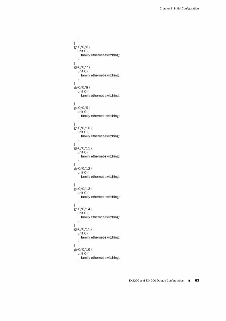
7/23/2019 Book Software Ex Series System Setup
http://slidepdf.com/reader/full/book-software-ex-series-system-setup 79/98
}}ge-0/0/6 {
unit 0 {
family ethernet-switching;}}ge-0/0/7 {
unit 0 {family ethernet-switching;
}}ge-0/0/8 {
unit 0 {family ethernet-switching;
}}ge-0/0/9 {
unit 0 {family ethernet-switching;
}}ge-0/0/10 {
unit 0 {family ethernet-switching;
}}ge-0/0/11 {
unit 0 {family ethernet-switching;
}}
ge-0/0/12 {unit 0 {
family ethernet-switching;}
}ge-0/0/13 {
unit 0 {family ethernet-switching;
}}ge-0/0/14 {
unit 0 {family ethernet-switching;
}
}ge-0/0/15 {
unit 0 {family ethernet-switching;
}}ge-0/0/16 {
unit 0 {family ethernet-switching;
}
EX3200 and EX4200 Default Configuration ■ 63
Chapter 3: Initial Configuration

7/23/2019 Book Software Ex Series System Setup
http://slidepdf.com/reader/full/book-software-ex-series-system-setup 80/98
}ge-0/0/17 {
unit 0 {family ethernet-switching;
}}ge-0/0/18 {
unit 0 {family ethernet-switching;
}}ge-0/0/19 {
unit 0 {family ethernet-switching;
}}ge-0/0/20 {
unit 0 {
family ethernet-switching;}
}ge-0/0/21 {
unit 0 {family ethernet-switching;
}}ge-0/0/22 {
unit 0 {family ethernet-switching;
}}ge-0/0/23 {
unit 0 {family ethernet-switching;
}}xe-0/1/0 {
unit 0 {family ethernet-switching;
}}xe-0/1/1 {
unit 0 {family ethernet-switching;
}}
ge-0/1/0 {unit 0 {
family ethernet-switching;}
}ge-0/1/1 {
unit 0 {family ethernet-switching;
}}
64 ■ EX3200 and EX4200 Default Configuration
JUNOS® Software Guide for EX Series Ethernet Switches, Release 9.6: System Setup
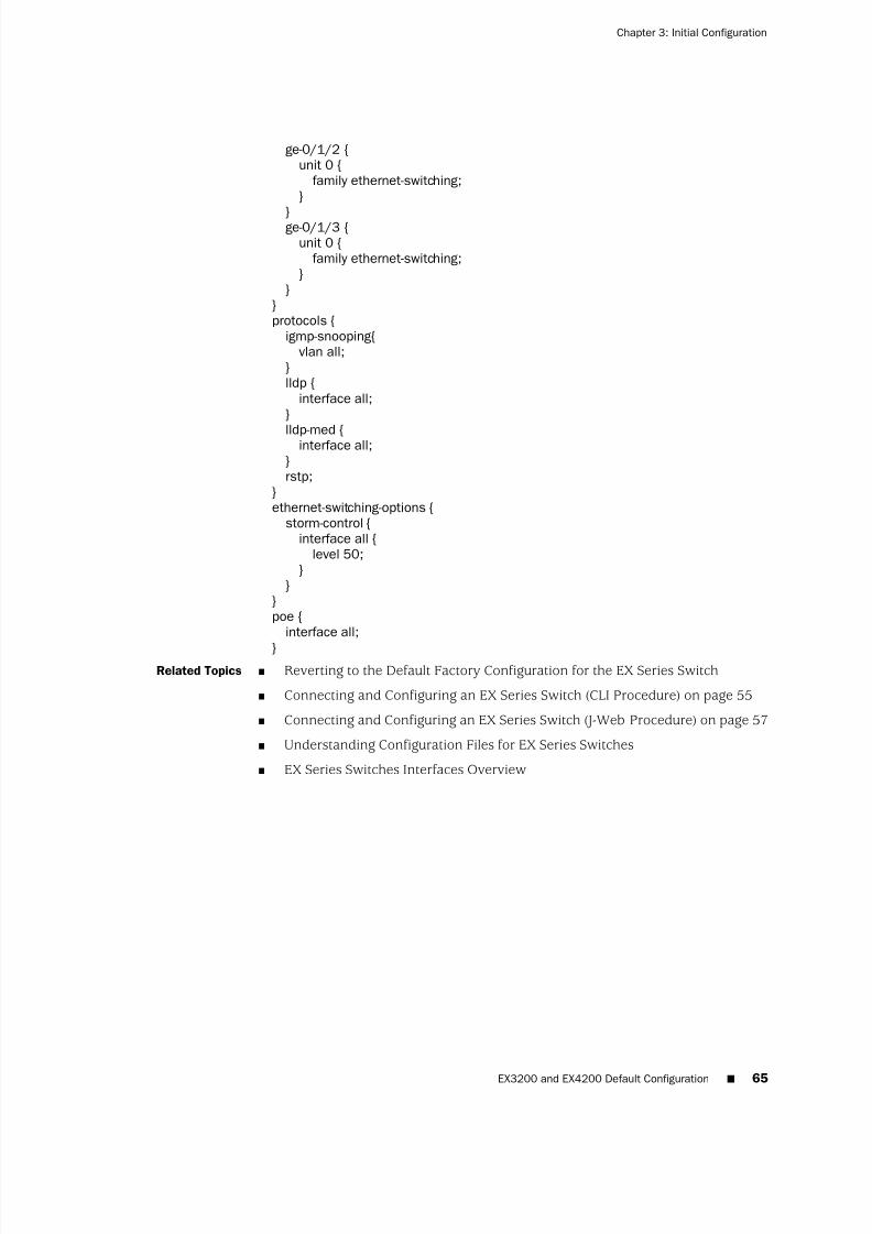
7/23/2019 Book Software Ex Series System Setup
http://slidepdf.com/reader/full/book-software-ex-series-system-setup 81/98
ge-0/1/2 {unit 0 {
family ethernet-switching;}
}ge-0/1/3 {unit 0 {
family ethernet-switching;}
}}protocols {
igmp-snooping{vlan all;
}lldp {
interface all;}
lldp-med {interface all;
}rstp;
}ethernet-switching-options {
storm-control {interface all {
level 50;}
}}poe {
interface all;
}Related Topics ■ Reverting to the Default Factory Configuration for the EX Series Switch
■ Connecting and Configuring an EX Series Switch (CLI Procedure) on page 55
■ Connecting and Configuring an EX Series Switch (J-Web Procedure) on page 57
■ Understanding Configuration Files for EX Series Switches
■ EX Series Switches Interfaces Overview
EX3200 and EX4200 Default Configuration ■ 65
Chapter 3: Initial Configuration

7/23/2019 Book Software Ex Series System Setup
http://slidepdf.com/reader/full/book-software-ex-series-system-setup 82/98
66 ■ EX3200 and EX4200 Default Configuration
JUNOS® Software Guide for EX Series Ethernet Switches, Release 9.6: System Setup
7/23/2019 Book Software Ex Series System Setup
http://slidepdf.com/reader/full/book-software-ex-series-system-setup 83/98
7/23/2019 Book Software Ex Series System Setup
http://slidepdf.com/reader/full/book-software-ex-series-system-setup 84/98
■ Border Gateway Protocol (BGP)
■ Intermediate System-to-Intermediate System (IS-IS)
■ IPv6 (except multicast protocols)
■ MPLS with RSVP-based label switched paths (LSPs) and MPLS-based circuitcross-connects (CCCs)
Related Topics ■ Managing Licenses for the EX Series Switch (CLI Procedure) on page 69
■ Managing Licenses for the EX Series Switch (J-Web Procedure) on page 70
■ Monitoring Licenses for the EX Series Switch on page 72
■ License Key Components for the EX Series Switch on page 68
■ EX Series Switch Software Features Overview on page 3
License Key Components for the EX Series Switch
When you purchase a license for a JUNOS Software feature that requires a separatelicense, you receive a license key.
A license key consists of two parts:
■ License ID—Alphanumeric string that uniquely identifies the license key. Whena license is generated, it is given a license ID.
■ License data—Block of binary data that defines and stores all license key objects.
For example, in the following typical license key, the string li29183743 is the licenseID, and the trailing block of data is the license data:
li29183743 4ky27y acasck 82fsj6 jzsn4q ix8i8d adj7kr
8uq38t ix8i8d jzsn4q ix8i8d 4ky27y acasck
82fsj6 ii8i7e adj7kr 8uq38t ks2923 a9382e
The license data defines the device ID for which the license is valid and the versionof the license.
Related Topics Managing Licenses for the EX Series Switch (CLI Procedure) on page 69■
■ Managing Licenses for the EX Series Switch (J-Web Procedure) on page 70
■ Software Licenses for the EX Series Switch Overview on page 67
Managing Software Licenses in EX Series Switches
■ Managing Licenses for the EX Series Switch (CLI Procedure) on page 69
■ Managing Licenses for the EX Series Switch (J-Web Procedure) on page 70
■ Registering the EX Series Switch with the J-Web Interface on page 72
68 ■ License Key Components for the EX Series Switch
JUNOS® Software Guide for EX Series Ethernet Switches, Release 9.6: System Setup

7/23/2019 Book Software Ex Series System Setup
http://slidepdf.com/reader/full/book-software-ex-series-system-setup 85/98
Managing Licenses for the EX Series Switch (CLI Procedure)
To enable some JUNOS Software features on an EX Series switch, you must purchase,install, and manage separate software licenses. Each switch requires one license perlicensed feature. The licenses are on an honor system, meaning that after you haveconfigured the features, you have a 30-day grace period to install the license. Youwill see a warning message if the switch does not have a license for the feature afterthose 30 days.
Before you begin managing licenses, be sure that you have:
■ Obtained the needed licenses. For information about how to purchase softwarelicenses, contact your Juniper Networks sales representative.
This topic includes the following tasks:
■
Adding New Licenses on page 69■ Deleting Licenses on page 70
■ Saving License Keys on page 70
Adding New Licenses
To add a new license key on the switch with CLI:
1. Enter one of the following operational mode CLI commands:
■ To add a license key from a file or URL, enter the following command,specifying the filename of the file or the URL where the key is located:
user@switch> request system license add filename | url
■ To add a license key from the terminal, enter the following command:
user@switch> request system license add terminal
2. When prompted, enter the license key, separating multiple license keys with ablank line.
If the license key you enter is invalid, an error appears in the CLI output whenyou press Ctrl+d to exit license entry mode.
Managing Licenses for the EX Series Switch (CLI Procedure) ■ 69
Chapter 4: License Management
7/23/2019 Book Software Ex Series System Setup
http://slidepdf.com/reader/full/book-software-ex-series-system-setup 86/98
7/23/2019 Book Software Ex Series System Setup
http://slidepdf.com/reader/full/book-software-ex-series-system-setup 87/98
1. In the J-Web interface, select Maintain>Licenses.
2. Under Installed Licenses, click Add to add a new license key.
3. Do one of the following, using a blank line to separate multiple license keys:
■ In the License File URL box, type the full URL to the destination file containingthe license key to be added.
■ In the License Key Text box, paste the license key text, in plain-text format,for the license to be added.
4. Click OK to add the license key.
A list of features that use the license key is displayed. The table also lists the ID, state,and version of the license key.
Deleting Licenses
To delete one or more license keys from a switch with the J-Web license manager:
1. In the J-Web interface, select Maintain>Licenses.
2. Select the check box of the license or licenses you want to delete.
3. Click Delete.
Displaying License Keys
To display the license keys installed on a switch with the J-Web license manager:
1. In the J-Web interface, select Maintain>Licenses.
2. Under Installed Licenses, click Display Keys to display all the license keys installedon the switch.
A screen displaying the license keys in text format appears. Multiple licenses areseparated by a blank line.
Downloading Licenses
To download the license keys installed on the switch with the J-Web license manager:
1. In the J-Web interface, select Maintain>Licenses.
2. Under Installed Licenses, click Download Keys to download all the license keysinstalled on the switch to a single file.
3. Select Save it to disk and specify the file to which the license keys are to bewritten. You can also download the license file to your system.
Related Topics Managing Licenses for the EX Series Switch (CLI Procedure) on page 69■
■ Monitoring Licenses for the EX Series Switch on page 72
Deleting Licenses ■ 71
Chapter 4: License Management
7/23/2019 Book Software Ex Series System Setup
http://slidepdf.com/reader/full/book-software-ex-series-system-setup 88/98
Registering the EX Series Switch with the J-Web Interface
To register the EX Series switch:
1. In the J-Web interface, select Maintain>Customer Support>Product Registration.
Note the serial number that is displayed.
2. Click Register. Enter the serial number in the page that is displayed.
Related Topics ■ EX Series Switch Software Features Overview on page 3
Monitoring Software Licenses in EX Series Switches
■ Monitoring Licenses for the EX Series Switch on page 72
Monitoring Licenses for the EX Series Switch
To enable and use some JUNOS Software features on the EX Series switch, you mustpurchase, install, and manage separate software licenses.
To monitor your installed licenses perform the following tasks:
■ Displaying Installed Licenses and License Usage Details on page 72
■ Displaying License Usage on page 73
■ Displaying Installed License Keys on page 73
Displaying Installed Licenses and License Usage DetailsPurpose Verify that the expected licenses are installed and active on the switch.
Action From the CLI, enter the show system license command.
Meaning The output shows a list of the license usage and a list of the licenses installed on theswitch. Verify the following information:
■ Each license is present. Licenses are listed in ascending alphanumeric order bylicense ID.
■ The state of each license is valid.
A state of invalid indicates that the license key is not a valid license key. Either it wasentered incorrectly or it is not valid for the specific device.
■ The feature for each license is the expected feature. The features enabled arelisted by license. An all-inclusive license has All features listed.
■ All configured features have the required licenses installed. The Licenses neededcolumn must show that no licenses are required.
72 ■ Registering the EX Series Switch with the J-Web Interface
JUNOS® Software Guide for EX Series Ethernet Switches, Release 9.6: System Setup
7/23/2019 Book Software Ex Series System Setup
http://slidepdf.com/reader/full/book-software-ex-series-system-setup 89/98
Displaying License Usage
Purpose Verify that the licenses fully cover the feature configuration on the switch.
Action From the CLI, enter the show system license usage command.
Meaning The output shows a list of the licenses installed on the switch and how they are used.Verify the following information:
■ Each licensed feature and port is present. Features and ports are listed inascending alphabetical order by license name. The number of licenses is shownin the fourth column. Verify that the appropriate number of licenses is installed.
■ The number of used licenses matches the number of configured features andports. If a licensed feature or port is configured, the feature or port is consideredused.
■ A license is installed on the switch for each configured feature and port. For
every feature or port configured that does not have a license, one license isneeded.
Displaying Installed License Keys
Purpose Verify that the expected license keys are installed on the switch.
Action From the CLI, enter the show system license keys command.
Meaning The output shows a list of the license keys installed on the switch. Verify that eachexpected license key is present.
Related Topics ■ Managing Licenses for the EX Series Switch (CLI Procedure) on page 69
■ Managing Licenses for the EX Series Switch (J-Web Procedure) on page 70
Displaying License Usage ■ 73
Chapter 4: License Management

7/23/2019 Book Software Ex Series System Setup
http://slidepdf.com/reader/full/book-software-ex-series-system-setup 90/98
74 ■ Displaying Installed License Keys
JUNOS® Software Guide for EX Series Ethernet Switches, Release 9.6: System Setup
7/23/2019 Book Software Ex Series System Setup
http://slidepdf.com/reader/full/book-software-ex-series-system-setup 91/98
Chapter 5
IP Address Management
■ IP Address Management Overview on page 75
■ IP Address Management Configuration on page 76
■ IP Address Management Monitoring on page 79
IP Address Management Overview
■ DHCP Services for EX Series Switches Overview on page 75
■ DHCP/BOOTP Relay for EX Series Switches Overview on page 76
DHCP Services for EX Series Switches Overview
A Dynamic Host Configuration Protocol (DHCP) server can automatically allocate IPaddresses and also deliver configuration settings to client hosts on a subnet.
DHCP is particularly useful for managing a pool of IP addresses among hosts. An IPaddress can be leased to a host for a limited period of time, allowing the DHCP server
to share a limited number of IP addresses among a group of hosts that do not needpermanent IP addresses.
DHCP, through the use of the automatic software download feature, can also be usedto install software packages on Juniper Networks EX Series Ethernet Switches. Userscan define a path to a software package on the DHCP server, and then the DHCPserver communicates this path to EX Series switches acting as DHCP clients as partof the DHCP message exchange process. The DHCP clients that have been configuredfor automatic software download receive these messages and, when the softwarepackage name in the DHCP server message is different from that of the softwarepackage that booted the DHCP client switch, download and install the softwarepackage. See “Upgrading Software Using Automatic Software Download on EX SeriesSwitches” on page 48.
To configure DHCP access service for an EX Series switch, you can use either the JUNOS command line interface (CLI) or the J-Web user interface.
For detailed information about configuring DHCP services, see the JUNOS SoftwareSystem Basics Configuration Guide at http://www.juniper.net/techpubs/
software/junos/junos96/index.html. The configuration for DHCP service on the EX Seriesswitch includes the dhcp statement at the [edit system services] hierarchy level. Thecommands and statements are the same as those used to configure DHCP for JuniperNetworks J Series Services Routers.
IP Address Management Overview ■ 75
7/23/2019 Book Software Ex Series System Setup
http://slidepdf.com/reader/full/book-software-ex-series-system-setup 92/98
You can monitor DHCP services for the switch by using either operational-mode CLIcommands or the J-Web interface.
Related Topics ■ For information about configuring DHCP services with the CLI, see the JUNOS Software System Basics Configuration Guide at http://www.juniper.net/techpubs/
software/junos/junos96/index.html.
■ Configuring DHCP Services (J-Web Procedure) on page 77
■ Upgrading Software Using Automatic Software Download on EX Series Switcheson page 48
■ Monitoring DHCP Services on page 79
DHCP/BOOTP Relay for EX Series Switches Overview
You can configure the Juniper Networks EX Series Ethernet Switch to act as a DynamicHost Configuration Protocol (DHCP) or Bootstrap Protocol (BOOTP) relay agent. This
means that a locally attached host can issue a DHCP or BOOTP request as a broadcastmessage. If the switch sees this broadcast message, it relays the message to a specifiedDHCP or BOOTP server. You should configure the switch to be a DHCP/BOOTP relayagent if you have locally attached hosts and a distant DHCP or BOOTP server.
For detailed information about configuring a DHCP/BOOTP relay agent, see the JUNOS Software Policy Framework Configuration Guide at http://www.juniper.net/techpubs/
software/junos/junos93/index.html. The configuration of the switch to act as aDHCP/BOOTP relay agent includes the bootp statement at the [edit forwarding-optionshelpers] hierarchy level. The commands and statements are the same as those usedto configure a DHCP/BOOTP relay agent on Juniper Networks routing platforms thatrun under Juniper Networks JUNOS Software.
NOTE: Because DHCP/BOOTP messages are broadcast and are not directed to aspecific server, switch, or router, EX Series switches cannot function as both a DHCPserver and a DHCP/BOOTP relay agent at the same time. JUNOS Software generatesa commit error if both options are configured at the same time, and the commit willnot succeed until one of the options is removed.
Related Topics For information about configuring the switch as a DHCP/BOOTP relay agent, seethe JUNOS Software Policy Framework Configuration Guide athttp://www.juniper.net/techpubs/software/junos/junos93/index.html.
■
■ DHCP Services for EX Series Switches Overview on page 75
IP Address Management Configuration
■ Configuring DHCP Services (J-Web Procedure) on page 77
76 ■ DHCP/BOOTP Relay for EX Series Switches Overview
JUNOS® Software Guide for EX Series Ethernet Switches, Release 9.6: System Setup
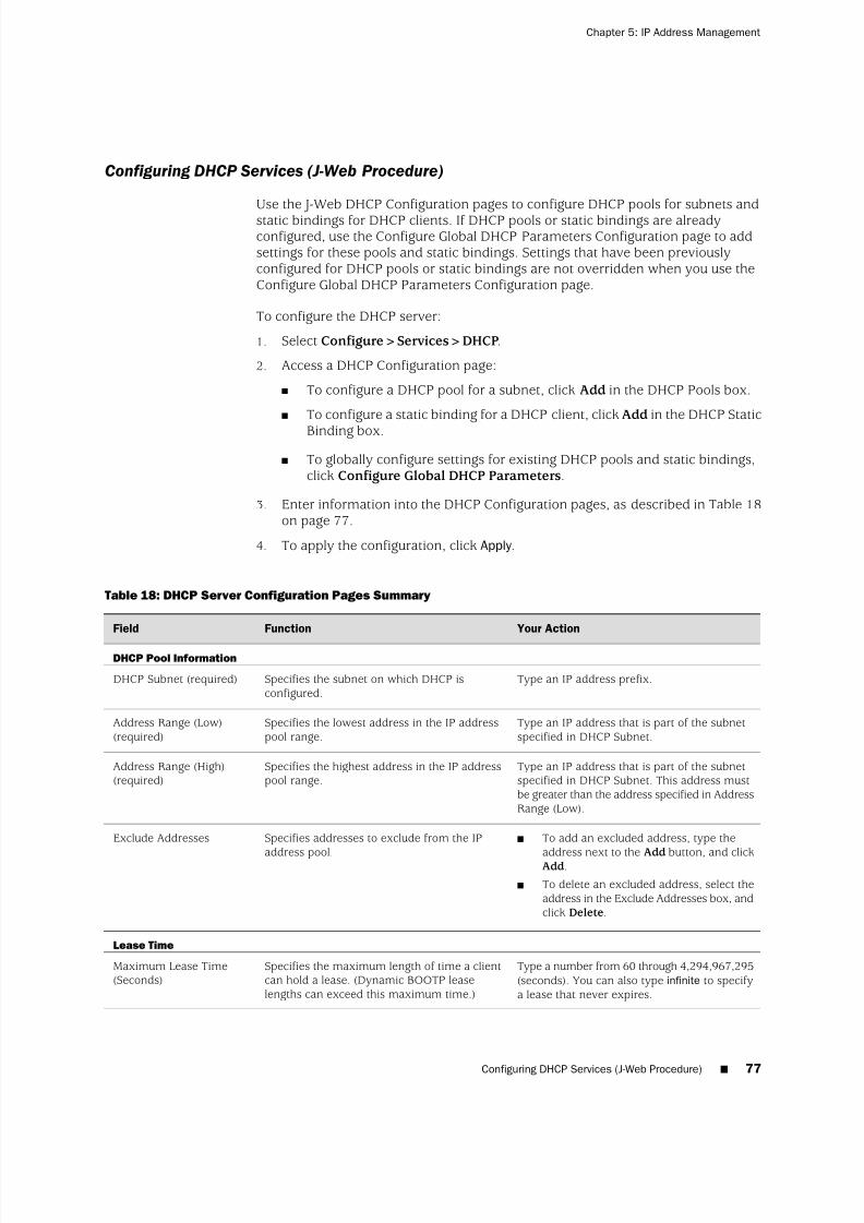
7/23/2019 Book Software Ex Series System Setup
http://slidepdf.com/reader/full/book-software-ex-series-system-setup 93/98
Configuring DHCP Services (J-Web Procedure)
Use the J-Web DHCP Configuration pages to configure DHCP pools for subnets andstatic bindings for DHCP clients. If DHCP pools or static bindings are alreadyconfigured, use the Configure Global DHCP Parameters Configuration page to addsettings for these pools and static bindings. Settings that have been previouslyconfigured for DHCP pools or static bindings are not overridden when you use theConfigure Global DHCP Parameters Configuration page.
To configure the DHCP server:
1. Select Configure>Services>DHCP.
2. Access a DHCP Configuration page:
■ To configure a DHCP pool for a subnet, click Add in the DHCP Pools box.
■ To configure a static binding for a DHCP client, click Add in the DHCP Static
Binding box.
■ To globally configure settings for existing DHCP pools and static bindings,click Configure Global DHCP Parameters.
3. Enter information into the DHCP Configuration pages, as described in Table 18on page 77.
4. To apply the configuration, click Apply .
Table 18: DHCP Server Configuration Pages Summary
Your ActionFunctionField
DHCP Pool Information
Type an IP address prefix.Specifies the subnet on which DHCP isconfigured.
DHCP Subnet (required)
Type an IP address that is part of the subnetspecified in DHCP Subnet.
Specifies the lowest address in the IP addresspool range.
Address Range (Low)(required)
Type an IP address that is part of the subnetspecified in DHCP Subnet. This address mustbe greater than the address specified in AddressRange (Low).
Specifies the highest address in the IP addresspool range.
Address Range (High)(required)
■ To add an excluded address, type the
address next to the Add button, and clickAdd.
■ To delete an excluded address, select theaddress in the Exclude Addresses box, andclick Delete.
Specifies addresses to exclude from the IP
address pool.
Exclude Addresses
Lease Time
Type a number from 60 through 4,294,967,295(seconds). You can also type infinite to specifya lease that never expires.
Specifies the maximum length of time a clientcan hold a lease. (Dynamic BOOTP leaselengths can exceed this maximum time.)
Maximum Lease Time(Seconds)
Configuring DHCP Services (J-Web Procedure) ■ 77
Chapter 5: IP Address Management

7/23/2019 Book Software Ex Series System Setup
http://slidepdf.com/reader/full/book-software-ex-series-system-setup 94/98
Table 18: DHCP Server Configuration Pages Summary (continued)
Your ActionFunctionField
Type a number from 60 through 2,147,483,647(seconds). You can also type infinite to specifya lease that never expires.
Specifies the length of time a client can hold alease for clients that do not request a specificlease length.
Default Lease Time(Seconds)
Server Information
Type the IP address of the server. If you do notspecify a server identifier, the primary addressof the interface on which the DHCP exchangeoccurs is used.
Specifies the IP address of the DHCP serverreported to a client.
Server Identifier
Type the name of the domain.Specifies the domain name that clients mustuse to resolve hostnames.
Domain Name
■ To add a domain name, type the namenext to the Add button, and click Add.
■ To delete a domain name, select the namein the Domain Search box, and clickDelete.
Specifies the order—from top to bottom—inwhich clients must append domain nameswhen resolving hostnames using DNS.
Domain Search
■ To add a DNS server, type an IP addressnext to the Add button, and click Add.
■ To remove a DNS server, select the IPaddress in the DNS Name Servers box,and click Delete.
Defines a list of DNS servers the client can use,in the specified order—from top to bottom.
DNS Name Servers
■ To add a relay agent, type an IP addressnext to the Add button, and click Add.
■ To remove a relay agent, select the IP
address in the Gateway Routers box, andclick Delete.
Defines a list of relay agents on the subnet, inthe specified order—from top to bottom.
Gateway Routers
■ To add a NetBIOS name server, type anIP address next to the Add button, andclick Add.
■ To remove a NetBIOS name server, selectthe IP address in the WINS Servers box,and click Delete.
Defines a list of NetBIOS name servers, in thespecified order—from top to bottom.
WINS Servers
Boot Options
Type a path and filename.Specifies the path and filename of the initialboot file to be used by the client.
Boot File
Type the IP address or hostname of the TFTPserver.Specifies the TFTP server that provides theinitial boot file to the client.Boot Server
DHCP Static Binding Information
Type the hexadecimal MAC address of theclient.
Specifies the MAC address of the client to bepermanently assigned a static IP address.
DHCP MAC Address(required)
78 ■ Configuring DHCP Services (J-Web Procedure)
JUNOS® Software Guide for EX Series Ethernet Switches, Release 9.6: System Setup
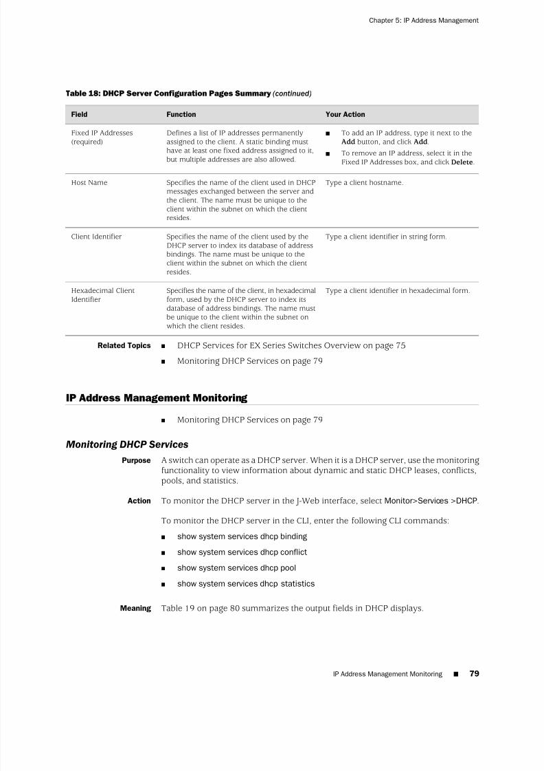
7/23/2019 Book Software Ex Series System Setup
http://slidepdf.com/reader/full/book-software-ex-series-system-setup 95/98
Table 18: DHCP Server Configuration Pages Summary (continued)
Your ActionFunctionField
■ To add an IP address, type it next to theAdd button, and click Add.
■ To remove an IP address, select it in theFixed IP Addresses box, and click Delete.
Defines a list of IP addresses permanentlyassigned to the client. A static binding musthave at least one fixed address assigned to it,but multiple addresses are also allowed.
Fixed IP Addresses(required)
Type a client hostname.Specifies the name of the client used in DHCPmessages exchanged between the server andthe client. The name must be unique to theclient within the subnet on which the clientresides.
Host Name
Type a client identifier in string form.Specifies the name of the client used by theDHCP server to index its database of addressbindings. The name must be unique to theclient within the subnet on which the client
resides.
Client Identifier
Type a client identifier in hexadecimal form.Specifies the name of the client, in hexadecimalform, used by the DHCP server to index itsdatabase of address bindings. The name mustbe unique to the client within the subnet onwhich the client resides.
Hexadecimal ClientIdentifier
Related Topics DHCP Services for EX Series Switches Overview on page 75■
■ Monitoring DHCP Services on page 79
IP Address Management Monitoring
■ Monitoring DHCP Services on page 79
Monitoring DHCP Services
Purpose A switch can operate as a DHCP server. When it is a DHCP server, use the monitoringfunctionality to view information about dynamic and static DHCP leases, conflicts,pools, and statistics.
Action To monitor the DHCP server in the J-Web interface, select Monitor>Services >DHCP.
To monitor the DHCP server in the CLI, enter the following CLI commands:
■
show system services dhcp binding■ show system services dhcp conflict
■ show system services dhcp pool
■ show system services dhcp statistics
Meaning Table 19 on page 80 summarizes the output fields in DHCP displays.
IP Address Management Monitoring ■ 79
Chapter 5: IP Address Management

7/23/2019 Book Software Ex Series System Setup
http://slidepdf.com/reader/full/book-software-ex-series-system-setup 96/98
Table 19: Summary of DHCP Output Fields
Additional InformationValuesField
DHCP Leases
List of IP addresses the DHCP server has assigned toclients.
AllocatedAddress
Corresponding media access control (MAC) addressof the client.
MACAddress
DHCP servers can assign a dynamic binding from a poolof IP addresses or a static binding to one or morespecific IP addresses.
Type of binding assigned to the client: dynamic orstatic.
BindingType
Date and time the lease expires, or never for leasesthat do not expire.
LeaseExpires
DHCP Conflicts
Date and time the client detected the conflict.DetectionTime
Only client-detected conflicts are displayed.How the conflict was detected.DetectionMethod
The addresses in the conflicts list remain excluded untilyou use the clear system services dhcp conflict commandto manually clear the list.
IP address where the conflict occurs.Address
DHCP Pools
Subnet on which the IP address pool is defined.Pool Name
Lowest address in the IP address pool.LowAddress
Highest address in the IP address pool.HighAddress
Addresses excluded from the address pool.ExcludedAddresses
DHCP Statistics
Lease time assigned to clients that do not request aspecific lease time.
Defaultlease time
Minimum time a client can retain an IP address leaseon the server.
Minimumlease time
Maximum time a client can retain an IP address leaseon the server.
Maximumlease time
Total number of packets dropped and the number of packets dropped due to a particular condition.
Packetsdropped
80 ■ Monitoring DHCP Services
JUNOS® Software Guide for EX Series Ethernet Switches, Release 9.6: System Setup

7/23/2019 Book Software Ex Series System Setup
http://slidepdf.com/reader/full/book-software-ex-series-system-setup 97/98
Table 19: Summary of DHCP Output Fields (continued)
Additional InformationValuesField
Number of BOOTREQUEST, DHCPDECLINE,DHCPDISCOVER, DHCPINFORM, DHCPRELEASE,and DHCPREQUEST messages sent from DHCP clientsand received by the DHCP server.
Messagesreceived
Number of BOOTREPLY, DHCPACK, DHCPOFFER,and DHCPNAK messages sent from the DHCP serverto DHCP clients.
Messagessent
Related Topics ■ DHCP Services for EX Series Switches Overview on page 75
■ Configuring DHCP Services (J-Web Procedure) on page 77
Monitoring DHCP Services ■ 81
Chapter 5: IP Address Management

7/23/2019 Book Software Ex Series System Setup
http://slidepdf.com/reader/full/book-software-ex-series-system-setup 98/98
JUNOS® Software Guide for EX Series Ethernet Switches, Release 9.6: System Setup