boostxl-tlv8544pir user's guide (rev. a)
TRANSCRIPT
1SNOU148A–March 2017–Revised April 2017Submit Documentation Feedback
Copyright © 2017, Texas Instruments Incorporated
BOOSTXL-TLV8544PIR User's Guide
User's GuideSNOU148A–March 2017–Revised April 2017
BOOSTXL-TLV8544PIR User's Guide
This guide covers the operational details of the BOOSTXL-TLV8544PIR Launchpad BoosterPack moduleand the supporting GUI software. The BOOSTXL-TLV8544PIR demonstrates the quad, nanopower opamp (TLV8544) operating as an analog front end (AFE) in a passive infrared motion sensor system.
Contents1 General Description ......................................................................................................... 12 BOOSTXL-TLV8544PIR Hardware Setup ................................................................................ 53 CC2650 LaunchPad Application Firmware Installation ................................................................. 54 Software Installation ......................................................................................................... 95 Running the Application ................................................................................................... 166 BOOSTXL-TLV8544PIR BoosterPack Schematics.................................................................... 22
TrademarksAll trademarks are the property of their respective owners.
1 General DescriptionThe BOOSTXL-TLV8544, and its supporting GUI software are designed to work with TI’s SimpleLinkCC2650 multi-frequency 2.6-GHz wireless LaunchPad: LAUNCHXL-CC2650. This combination ofLaunchPad and BoosterPack allows users to evaluate the operation and performance of the TLV8544.• The TLV8544 quad nanopower op amp consumes nanoamperes per channel, maximizing the life of
the battery and motion sensor system. Reducing frequency of battery or unit replacement also reducestotal cost of ownership.
• Amplification, filtering and threshold detection is all performed by a single device, simplifying the designand reducing solution size
• This board design could easily be used as the basis for an ultra-low power, battery-operated, wirelessPIR or microwave motion sensing system, further simplifying design and speeding time to market.
An embedded I2C current sensor (INA226) provides real-time measurement of supply current to TLV8544.The current measurement value is streamed in real-time to the host software, and presented as both ananalog gauge and a digital readout.
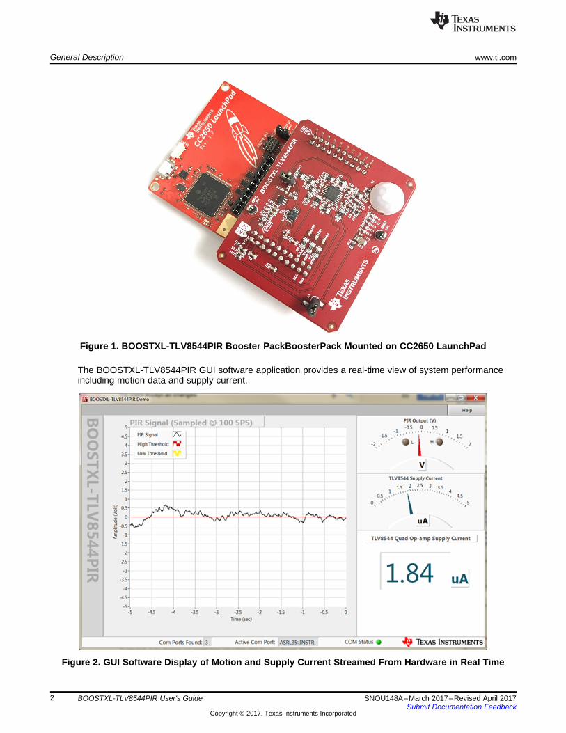
The BOOSTXL-TLV8544PIR BoosterPack is shown mounted on the CC2650 LaunchPad in Figure 1.Figure 2 shows the GUI software screenshot.
General Description www.ti.com
2 SNOU148A–March 2017–Revised April 2017Submit Documentation Feedback
Copyright © 2017, Texas Instruments Incorporated
BOOSTXL-TLV8544PIR User's Guide
Figure 1. BOOSTXL-TLV8544PIR Booster PackBoosterPack Mounted on CC2650 LaunchPad
The BOOSTXL-TLV8544PIR GUI software application provides a real-time view of system performanceincluding motion data and supply current.
Figure 2. GUI Software Display of Motion and Supply Current Streamed From Hardware in Real Time

U1A U
1B
U1C
U1D
Amplifier and BPF Stage
Band-pass FilterLow Cutoff Freq= 0.71 HzHigh Cutoff Freq= 10.7 Hz
PIR Sensor
¾ Vcc
½ VCC
¼ Vcc
¼ TLV8544
¼ TLV8544
¼ TLV8544
¼ TLV8544C4
+
-
+
-
+
-
AmplifierGain= 93 dB
INA226
15.0 k 0.1%
VccR21J4
4
4
4
4
V+
V+
V+
V+
J3Vcc
PIR Current Measurement Jumper
TLV8544 Current Measurement Jumper
Window Comparator Stage
J1
Launchpad Connector (J3)
14, 17,19
1
VIN
VOUT
10
11
12
High Threshold Output (D)
Low Threshold Output (D)
PIR Signal Output (A)
3.3V Power Supply
I2C Port
A1
Green LED
Red LED
Yellow LED
16
18
20
www.ti.com General Description
3SNOU148A–March 2017–Revised April 2017Submit Documentation Feedback
Copyright © 2017, Texas Instruments Incorporated
BOOSTXL-TLV8544PIR User's Guide
1.1 BOOSTXL-TLV8544PIR Conceptual DiagramFigure 3 is a conceptual view of the key features of the BoosterPack. There are 3 primary functionalblocks supported:1. An amplifier and filter stage which increases the magnitude of the signal, filters out unwanted
information, and level-shifts the signal to enable the second functional block2. A Window Comparator stage which detects high and low threshold crossing events. The thresholds are
fixed to ¾ VCC and ¼ VCC, respectively3. An embedded current sensor (INA226) for measuring TLV8544 supply current in real-time
Figure 3 provides additional details of the primary functions.
Figure 3. BOOSTXL TLV8544PIR BoosterPack Conceptual Diagram
General Description www.ti.com
4 SNOU148A–March 2017–Revised April 2017Submit Documentation Feedback
Copyright © 2017, Texas Instruments Incorporated
BOOSTXL-TLV8544PIR User's Guide
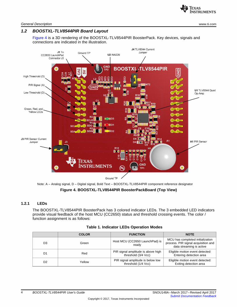
1.2 BOOSTXL-TLV8544PIR Board LayoutFigure 4 is a 3D rendering of the BOOSTXL-TLV8544PIR BoosterPack. Key devices, signals andconnections are indicated in the illustration.
Note: A – Analog signal, D – Digital signal, Bold Text – BOOSTXL-TLV8544PIR component reference designator
Figure 4. BOOSTXL-TLV8544PIR BoosterPackBoard (Top View)
1.2.1 LEDsThe BOOSTXL-TLV8544PIR BoosterPack has 3 colored indicator LEDs. The 3 embedded LED indicatorsprovide visual feedback of the host MCU (CC2650) status and threshold crossing events. The color /function assignment is as follows:
Table 1. Indicator LEDs Operation Modes
COLOR FUNCTION NOTE
D3 Green Host MCU (CC2650 LaunchPad) isready
MCU has completed initializationprocess. PIR signal acquisition and
data streaming is active
D1 Red PIR signal amplitude is above highthreshold (3/4 Vcc)
Eligible motion event detected:Entering detection area
D2 Yellow PIR signal amplitude is below lowthreshold (1/4 Vcc)
Eligible motion event detected:Exiting detection area
www.ti.com BOOSTXL-TLV8544PIR Hardware Setup
5SNOU148A–March 2017–Revised April 2017Submit Documentation Feedback
Copyright © 2017, Texas Instruments Incorporated
BOOSTXL-TLV8544PIR User's Guide
1.2.2 Jumper Blocks and Test PointsThe 2 jumper connectors, J3 and J4, can be used to measure supply current to the PIR sensor (A1) andthe TLV8544 (U1), respectively. To perform current measurement, remove the jumper block, then connectthe 2 pins to a current meter. The meter must be capable of measuring low current values (<10 µA).Typically, while no motion is detected, the current to the PIR sensor (through J3) measures about 0.5 µAwhile the TLV8544 (through J4) about 1.7 µA.
To return to normal operation, jumper blocks must be replaced on both J3 and J4.
The 2 ground test points are handy for instrumentation grounding.
2 BOOSTXL-TLV8544PIR Hardware SetupBefore handling hardware, make sure the proper anti-static and safety precaution procures are followed.
2.1 BoosterPack InstallationTo install BOOSTXL-TLV8544PIR BoosterPack onto the LaunchPad, check the alignment of the 2 boardsusing Figure 1 as a reference. Gently place the BoosterPack on the LaunchPad and make sure the pins ofthe 2 connectors are aligned properly. Gradually apply force on the BoosterPack until it’s fully plugged in.Stop and check alignment if excessive resistance is detected.
Visually inspect the BoosterPack placement. If everything looks as expected, connect the LaunchPad tothe PC using the provided Micro USB cable. The green LED on the LaunchPad should illuminate uponconnection.
2.2 Stand-Alone Motion Detection With Embedded LEDsOnce the firmware has been installed, the BoosterPack/LaunchPad bundle is capable of performingmotion detection with embedded LEDs. The red and yellow LEDs represent high and low thresholdcrossing events respectively. The high and low-thresholds are fixed at ¾ VCC (red) and ¼ VCC (yellow).When PIR signal amplitude is within ¼ VCC and ¾ VCC, both the red and yellow LEDs are turned off,however, the green LED remains illuminated.
3 CC2650 LaunchPad Application Firmware Installation
3.1 CC2650 LaunchPad Firmware Installer Software
1. Go to TI’s official download page to download the CC2650 LaunchPad Firmware Installer software(http://www.ti.com/tool/FLASH-PROGRAMMER). Select FLASH-PROGRAMMER-2 and clickdownload.
2. Complete the export compliance questionnaire accurately, then submit. When approval is received,click download. The downloaded file will be a zipped file.
3. Extract the contents of the zip file to a known location and run the setup executable.4. Follow the on-screen prompts, accept the License Agreement, then continue.5. Continue through the prompts to install the software.6. Click Finish when done.
For technical support, please visit the TI LaunchPad Kit page.
3.1.1 LaunchPad Application Firmware Installation
1. Download the firmware binary BOOSTXL-TLV8544PIR_LP.out available at ti.com/BOOSTXL-TLV8544PIR and save it to a known location.
2. Run SmartRF Flash Programmer 2 by clicking on Flash Programmer 2 under Windows Program Menu- Texas Instruments/SmartRF Flash Programmer 2/
3. If your LaunchPad requires system firmware update, the following screen is shown as follows. If thesystem firmware is up-to-date, skip to next step. In the left panel called Connected Devices, click on

CC2650 LaunchPad Application Firmware Installation www.ti.com
6 SNOU148A–March 2017–Revised April 2017Submit Documentation Feedback
Copyright © 2017, Texas Instruments Incorporated
BOOSTXL-TLV8544PIR User's Guide
Unknown below XDS110, SDS-L1. See Figure 5
Figure 5. LaunchPad System Firmware Needs Update
A dialog box offering to update firmware will open (see Figure 6). Click Yes, then click Done.
Figure 6. Click Yes (to System Firmware Update Request)
After the system firmware update is complete, the unknown under XDS110, XDS-L10… drop-down listin the left panel (Connected Devices), should be replaced by CC2650, as shown in Figure 7.
www.ti.com CC2650 LaunchPad Application Firmware Installation
7SNOU148A–March 2017–Revised April 2017Submit Documentation Feedback
Copyright © 2017, Texas Instruments Incorporated
BOOSTXL-TLV8544PIR User's Guide
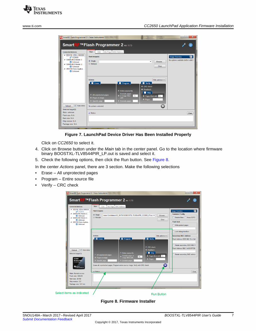
Figure 7. LaunchPad Device Driver Has Been Installed Properly
Click on CC2650 to select it.4. Click on Browse button under the Main tab in the center panel. Go to the location where firmware
binary BOOSTXL-TLV8544PIR_LP.out is saved and select it.5. Check the following options, then click the Run button. See Figure 8.
In the center Actions panel, there are 3 section. Make the following selections• Erase – All unprotected pages• Program – Entire source file• Verify – CRC check
Figure 8. Firmware Installer
CC2650 LaunchPad Application Firmware Installation www.ti.com
8 SNOU148A–March 2017–Revised April 2017Submit Documentation Feedback
Copyright © 2017, Texas Instruments Incorporated
BOOSTXL-TLV8544PIR User's Guide
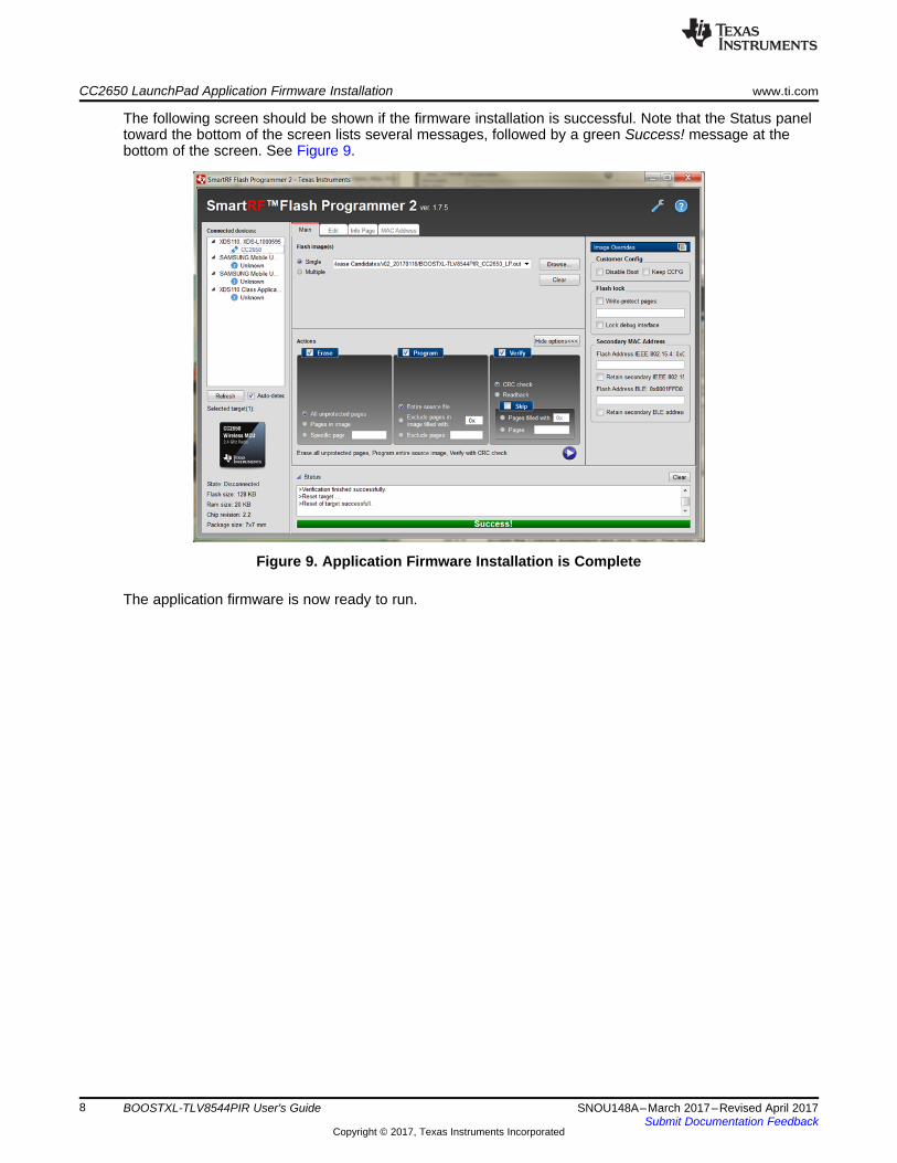
The following screen should be shown if the firmware installation is successful. Note that the Status paneltoward the bottom of the screen lists several messages, followed by a green Success! message at thebottom of the screen. See Figure 9.
Figure 9. Application Firmware Installation is Complete
The application firmware is now ready to run.

www.ti.com Software Installation
9SNOU148A–March 2017–Revised April 2017Submit Documentation Feedback
Copyright © 2017, Texas Instruments Incorporated
BOOSTXL-TLV8544PIR User's Guide
4 Software InstallationThe software installation process includes Windows driver installation and the application installation.Unless otherwise noted, user is expected to choose default options.
4.1 CC2650 LaunchPad Windows Driver InstallationThe Windows device drivers should have been installed during LaunchPad Firmware Installer softwareinstallation. To check, opening Windows Device Manager and look for entry XDS110 Application/UserUART (COMnn) under Ports (COM & LPT). Figure 10 shows the drivers have not been installed.
Figure 10. Windows Driver Has Not Been Installed

Software Installation www.ti.com
10 SNOU148A–March 2017–Revised April 2017Submit Documentation Feedback
Copyright © 2017, Texas Instruments Incorporated
BOOSTXL-TLV8544PIR User's Guide
Figure 11 shows the drivers have been successfully installed.
Figure 11. Windows Driver Has Been Installed Already
If the drivers are installed, simply go to next step. Otherwise, download the driver from TI’s official page(http://processors.wiki.ti.com/index.php/XDS_Emulation_Software_Package). Right-click on the EXE fileand select Run as administrator. The following dialog box will open (see Figure 12):
Figure 12. Windows Driver Installation
www.ti.com Software Installation
11SNOU148A–March 2017–Revised April 2017Submit Documentation Feedback
Copyright © 2017, Texas Instruments Incorporated
BOOSTXL-TLV8544PIR User's Guide
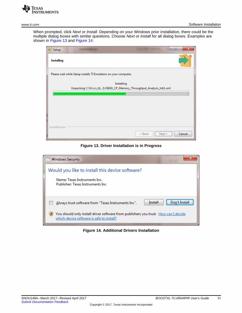
When prompted, click Next or Install. Depending on your Windows prior installation, there could be themultiple dialog boxes with similar questions. Choose Next or Install for all dialog boxes. Examples areshown in Figure 13 and Figure 14.
Figure 13. Driver Installation is in Progress
Figure 14. Additional Drivers Installation

Software Installation www.ti.com
12 SNOU148A–March 2017–Revised April 2017Submit Documentation Feedback
Copyright © 2017, Texas Instruments Incorporated
BOOSTXL-TLV8544PIR User's Guide
Upon successful installation of the necessary drivers, the dialog box will say that Setup has finishedinstalling TI Emulators on your computer. Click Finish (see Figure 15).
Figure 15. Windows Device Drivers Installation Successful
The driver installation process may take a few minutes depending on the PC’s speed. If the installation issuccessful, proceed to the next step.
If there are issues during installation, reboot the PC and try the process again. If problem persists, pleasevisit http://processors.wiki.ti.com/index.php/XDS_Emulation_Software_Package for solutions.

www.ti.com Software Installation
13SNOU148A–March 2017–Revised April 2017Submit Documentation Feedback
Copyright © 2017, Texas Instruments Incorporated
BOOSTXL-TLV8544PIR User's Guide
4.2 GUI Application Software InstallationTo start the installation process, navigate to the BOOSTXL-TLV8544PIR folder, right-click on setup.exeand select Run as administrator. Default settings are recommended for all steps.
After accepting the license agreement, then the next dialog box determines the location of the directory forinstalling the GUI application software. Keep default selections and click Next (see Figure 16).
Figure 16. Use Default Settings and Click on Next>>
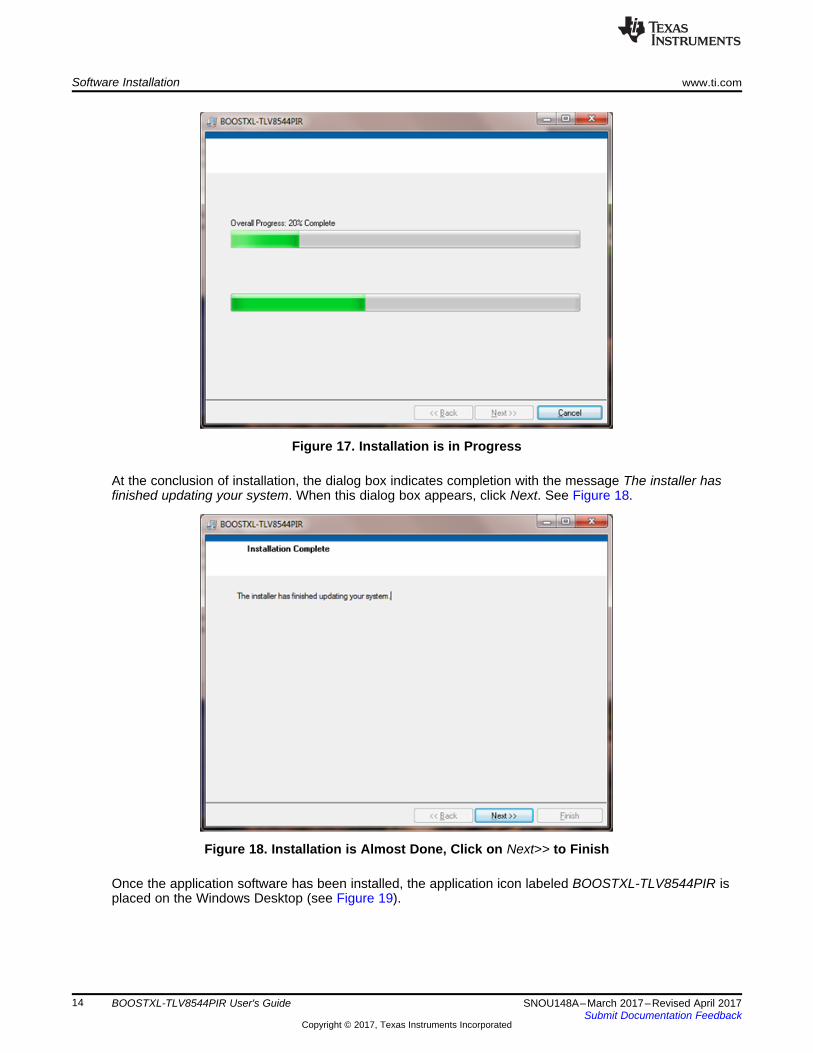
The next dialog indicates the installation status with status bars. See Figure 17.
Software Installation www.ti.com
14 SNOU148A–March 2017–Revised April 2017Submit Documentation Feedback
Copyright © 2017, Texas Instruments Incorporated
BOOSTXL-TLV8544PIR User's Guide
Figure 17. Installation is in Progress
At the conclusion of installation, the dialog box indicates completion with the message The installer hasfinished updating your system. When this dialog box appears, click Next. See Figure 18.
Figure 18. Installation is Almost Done, Click on Next>> to Finish
Once the application software has been installed, the application icon labeled BOOSTXL-TLV8544PIR isplaced on the Windows Desktop (see Figure 19).

www.ti.com Software Installation
15SNOU148A–March 2017–Revised April 2017Submit Documentation Feedback
Copyright © 2017, Texas Instruments Incorporated
BOOSTXL-TLV8544PIR User's Guide
Figure 19. An Icon With Label tlv8544 is Placed on Windows Desktop as Well as at Start Menu
Running the Application www.ti.com
16 SNOU148A–March 2017–Revised April 2017Submit Documentation Feedback
Copyright © 2017, Texas Instruments Incorporated
BOOSTXL-TLV8544PIR User's Guide
5 Running the Application
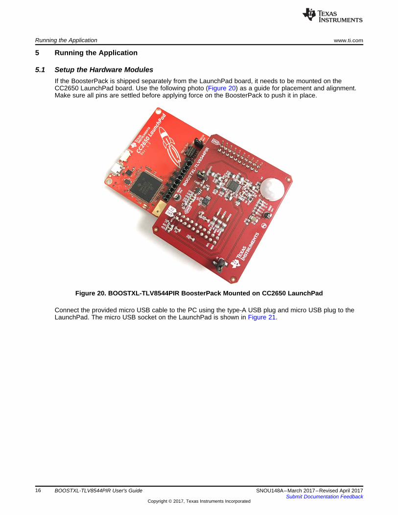
5.1 Setup the Hardware ModulesIf the BoosterPack is shipped separately from the LaunchPad board, it needs to be mounted on theCC2650 LaunchPad board. Use the following photo (Figure 20) as a guide for placement and alignment.Make sure all pins are settled before applying force on the BoosterPack to push it in place.
Figure 20. BOOSTXL-TLV8544PIR BoosterPack Mounted on CC2650 LaunchPad
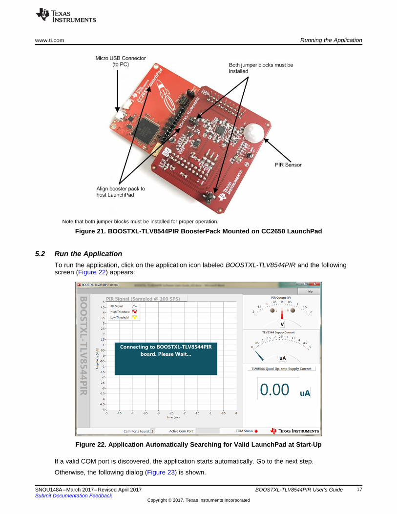
Connect the provided micro USB cable to the PC using the type-A USB plug and micro USB plug to theLaunchPad. The micro USB socket on the LaunchPad is shown in Figure 21.
www.ti.com Running the Application
17SNOU148A–March 2017–Revised April 2017Submit Documentation Feedback
Copyright © 2017, Texas Instruments Incorporated
BOOSTXL-TLV8544PIR User's Guide
Note that both jumper blocks must be installed for proper operation.
Figure 21. BOOSTXL-TLV8544PIR BoosterPack Mounted on CC2650 LaunchPad
5.2 Run the ApplicationTo run the application, click on the application icon labeled BOOSTXL-TLV8544PIR and the followingscreen (Figure 22) appears:
Figure 22. Application Automatically Searching for Valid LaunchPad at Start-Up
If a valid COM port is discovered, the application starts automatically. Go to the next step.
Otherwise, the following dialog (Figure 23) is shown.

Running the Application www.ti.com
18 SNOU148A–March 2017–Revised April 2017Submit Documentation Feedback
Copyright © 2017, Texas Instruments Incorporated
BOOSTXL-TLV8544PIR User's Guide
Figure 23. The Application Can’t Find Valid LaunchPad to Connect
In this case, click on the Quit button and the software will exit. Check the Windows Device driver has beenproperly installed detailed in Section 3.1. Click on the icon again to re-launch the application. If the sameissue persists, unplug the USB connector find another USB port to use. If no other port available, justremove and insert it into the same port.
Once the application starts, the following screen appears (see Figure 24). Note that for the first time theBoosterPack is powered up, there is up to 30-second delay before the output becomes valid.
Figure 24. Application Running
www.ti.com Running the Application
19SNOU148A–March 2017–Revised April 2017Submit Documentation Feedback
Copyright © 2017, Texas Instruments Incorporated
BOOSTXL-TLV8544PIR User's Guide
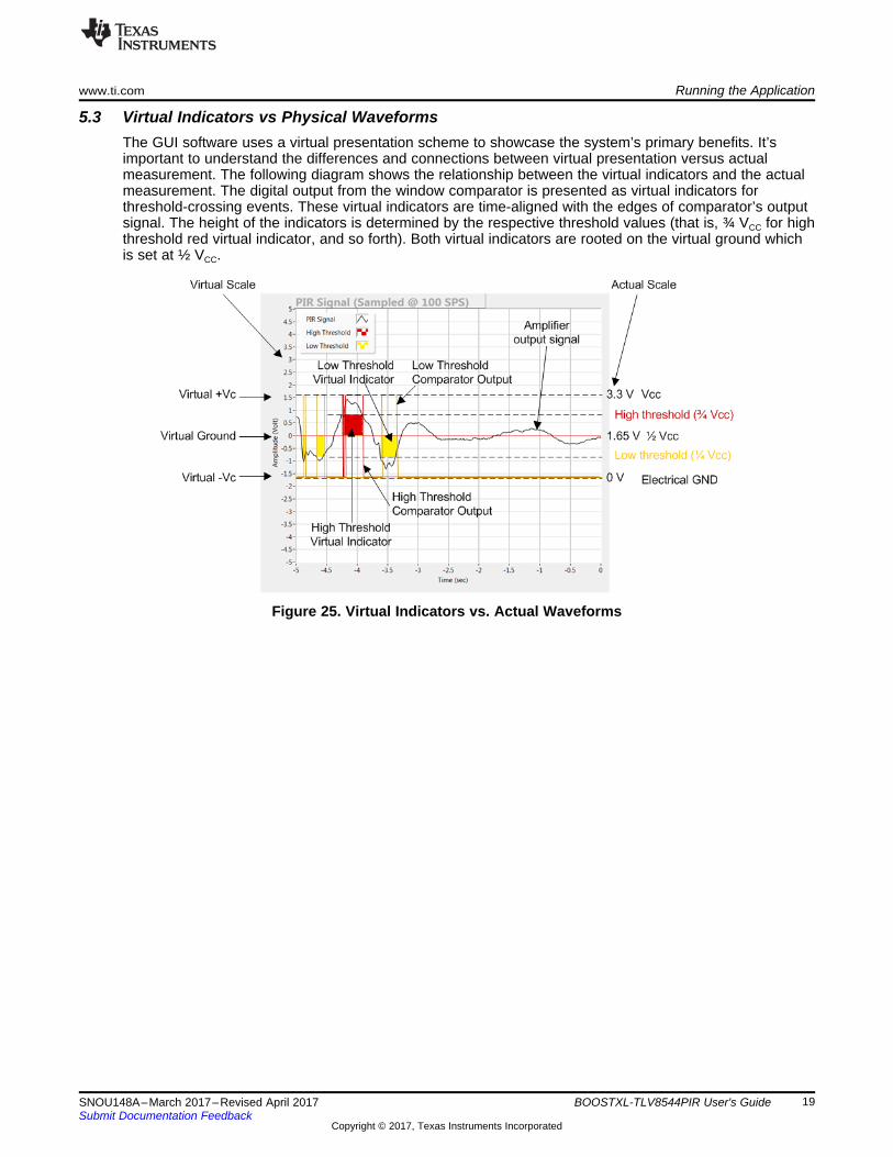
5.3 Virtual Indicators vs Physical WaveformsThe GUI software uses a virtual presentation scheme to showcase the system’s primary benefits. It’simportant to understand the differences and connections between virtual presentation versus actualmeasurement. The following diagram shows the relationship between the virtual indicators and the actualmeasurement. The digital output from the window comparator is presented as virtual indicators forthreshold-crossing events. These virtual indicators are time-aligned with the edges of comparator’s outputsignal. The height of the indicators is determined by the respective threshold values (that is, ¾ VCC for highthreshold red virtual indicator, and so forth). Both virtual indicators are rooted on the virtual ground whichis set at ½ VCC.
Figure 25. Virtual Indicators vs. Actual Waveforms
Running the Application www.ti.com
20 SNOU148A–March 2017–Revised April 2017Submit Documentation Feedback
Copyright © 2017, Texas Instruments Incorporated
BOOSTXL-TLV8544PIR User's Guide
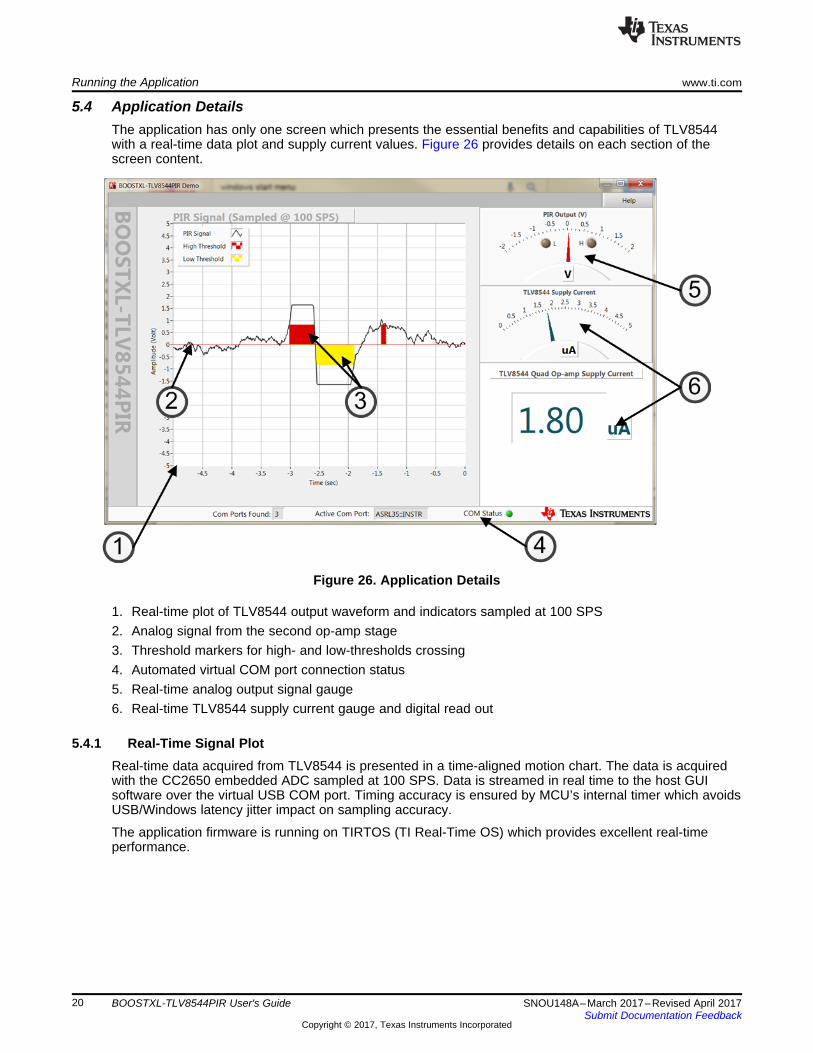
5.4 Application DetailsThe application has only one screen which presents the essential benefits and capabilities of TLV8544with a real-time data plot and supply current values. Figure 26 provides details on each section of thescreen content.
Figure 26. Application Details
1. Real-time plot of TLV8544 output waveform and indicators sampled at 100 SPS2. Analog signal from the second op-amp stage3. Threshold markers for high- and low-thresholds crossing4. Automated virtual COM port connection status5. Real-time analog output signal gauge6. Real-time TLV8544 supply current gauge and digital read out
5.4.1 Real-Time Signal PlotReal-time data acquired from TLV8544 is presented in a time-aligned motion chart. The data is acquiredwith the CC2650 embedded ADC sampled at 100 SPS. Data is streamed in real time to the host GUIsoftware over the virtual USB COM port. Timing accuracy is ensured by MCU’s internal timer which avoidsUSB/Windows latency jitter impact on sampling accuracy.
The application firmware is running on TIRTOS (TI Real-Time OS) which provides excellent real-timeperformance.
www.ti.com Running the Application
21SNOU148A–March 2017–Revised April 2017Submit Documentation Feedback
Copyright © 2017, Texas Instruments Incorporated
BOOSTXL-TLV8544PIR User's Guide
5.4.2 Analog Signal From Second Op-Amp StageThe real-time plot presents a rolling waveform which provides a time-variant view on the data in thecontext of real-time physical environment in which people are in motion.
The data is plotted as-is without post-processing or filtering. This provides a realistic representation of theperformance, and benefits, of the TLV8544.
The TLV8544 is powered from a single 3.3-V supply and the reference voltage is established with adivider network. For a better illustration, the output analog signal is presented as ±1.65 V over a virtualground base.
5.4.3 Threshold Markers for High- and Low-ThresholdsTwo out of 4 op-amps in the quad package are used as comparators. The comparators’ output is digitalwith full rail to rail swing. There are 2 thresholds provided with ¼ of full scale as the low threshold; ¾ of fullscale as the high threshold. The 2 markers (yellow and red) in the plot use the threshold crossing pointsas the horizontal edges and respective high and low threshold levels as heights.
5.4.4 Automated Virtual COM Ports Scan and ConnectionTo make the software more user-friendly and to appeal a wider audience, special effort has been made tosimplify the setup process. Upon application start-up, USB virtual COM ports are automatically scanned tolocate the first valid Launchpad by monitoring a signature data sequence sent from the LaunchPad MCU.Once a valid device is found, connection is established automatically without user’s intervention.
When the process is completed successfully, the green COM Status indicator at the bottom status bar isturned on. Otherwise, the red indicator is turned on if the application has failed to connect. In this case,quite the application, unplug the PC side USB connector and re-plug it into another available USB port.Then re-launch the application and try again.
5.4.5 Analog Signal GaugeThe gauge provides a dynamic, instantaneous view of the analog reading from the second amplifier stageoutput.
5.4.6 Real-Time Supply CurrentThe supply current gauge shows the real-time instantaneous power consumption using a precision currentsensor. The current reading is calibrated with a HP 3458A precision multi-meter and a 0.1% toleranceshunt-sensing resistor ensures consistency. The gauge is useful to report in-situ power consumption ofop-amps under various operating conditions.
User LEDs
Red
12
D1
GND GND
Yellow
12
D2
4421%0.125W
R14871%0.125W
R2
4871%0.125W
R3
GND
Green
12
D3
D5
1N4148X-TP
VIN1
GND2
VOUT3
GND4
GND5
A1
GNDGND
GND
GND
1.50M
R9
D4
1N4148X-TP
1.30MR16
GND GND
10µFC11
3.3µF
C9
68.1k
R13
15M
R7
15MR8
15MR11
15MR18
15MR20
GND
GND
6.81kR6
PIR Sensor Signal Conditioning
GND
GND
0.1µFC13
619kR12
100pFC16
GND
0
R17
0
R15
GND
0
R14
100µFC10
0.01µFC14
33µFC5
2
3
1A
V+
V-
41
1
U1ATLV8544PWR
5
6
7B
V+
V-
41
1
U1BTLV8544PWR
8
10
9
CV+
V-
41
1
U1CTLV8544PWR
14
12
13
DV+
V-
41
1
U1DTLV8544PWR
V+_TLVV+_TLV
V+_TLV
V+_TLV
10µFC20
GND
0.1µFC19
GND
TLV8544 SupplyV+_TLV
10.0k
R4
10.0k
R5
10.0k
R10
10.0k
R19
0.01µF
C6
1000pF
C7
1000pFC15
0.1µFC17
0.1µFC8
0.1µFC18
PIR_VOPIR_VIN
3.3VREF
CC2650 Launchpad Connectors
1
3
56
4
2
7
910
8
12 11
14 13
16 15
18 17
20 19
J1
SSQ-110-03-G-D
1
3
56
4
2
7
910
8
12 11
14 13
16 15
18 17
20 19
J2
SSQ-110-03-G-DGND
I2C_SDA
I2C_SCL
GND
0.01µF
C3
GND
0.01µF
C4
GND
I2C_CS
GND
0.01µF
C2
0.01µF
C1
1STAG_AOUT
PIR_SGL_AOUT
PIR_OUT_HI
PIR_OUT_LO
1STAG_AOUT
PIR_SGL_AOUTGND
PIR_OUT_HI
PIR_OUT_LO
V+_PIR
V5_LPD = 5VGNDNCNCPIR_OUT_HI = DIO 27PIR_OUT_LO =DIO 28I2C_CS = DIO 29OLED = DIO 30RLED = DIO 0YLED = DIO 1
V5_LPD V3P3_LPD
OLEDRLEDYLED
OLEDRLED YLED
TP1
GND
V3P3_LPD = 3.3V1STAG_AOUT = A0 DIO 23NCNCNCPIR_SGL_AOUT = A1 DIO 24NCNCI2C_SCL = DIO 4I2C_SDA = DIO 5
Launchpad J3 Launchpad J1
Launchpad J4 Launchpad J2
1µFC12
Copyright © 2016, Texas Instruments Incorporated
BOOSTXL-TLV8544PIR BoosterPack Schematics www.ti.com
22 SNOU148A–March 2017–Revised April 2017Submit Documentation Feedback
Copyright © 2017, Texas Instruments Incorporated
BOOSTXL-TLV8544PIR User's Guide
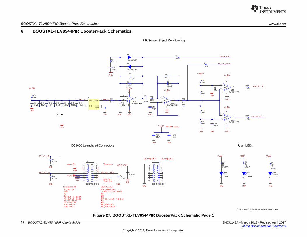
6 BOOSTXL-TLV8544PIR BoosterPack Schematics
Figure 27. BOOSTXL-TLV8544PIR BoosterPack Schematic Page 1

1500 ohmBLM18HE152SN1D
L1
A11
A02
ALERT3
SDA4
SCL5
VS+6
GND7
VBUS8
VIN-9
VIN+10
U2
INA226AIDGSR
0.1µFC21
GND
GND GND
I2C_SDA
I2C_SCL
I2C_CS
0.1µF6.3VX7R
C26
GND
0.1µF6.3VX7R
C27
GND GNDGND
1500 ohmBLM18HE152SN1D
L2
10µF6.3X5R
C280.1µF25X7R
C29
GND
5V
0.1µFC23
GND
Place caps at the Launpad connector pin
Place caps at the Launpad connector pin
3.3VINA
3.3VTLV
0.1µFC22
3.3VTLVV+_TLV
1
2
J4
87898-0204SH-JP2
V3P3_LPD15.0kR21
H1
IML-0669
12
J387898-0204
SH-JP1
V+_PIR
5V
NT1
0.1µF6.3VX7R
C24
GND GND
10µF6.3X5R
C25
3.3V
NT2
3.3VTLV 3.3VREF
NT3
3.3VINA
V5_LPD
TP2
GND
4
3
2
1
5
V+
V-
U3
Copyright © 2016, Texas Instruments Incorporated
www.ti.com BOOSTXL-TLV8544PIR BoosterPack Schematics
23SNOU148A–March 2017–Revised April 2017Submit Documentation Feedback
Copyright © 2017, Texas Instruments Incorporated
BOOSTXL-TLV8544PIR User's Guide
Figure 28. BOOSTXL-TLV8544PIR BoosterPack Schematic Page 2
Revision History www.ti.com
24 SNOU148A–March 2017–Revised April 2017Submit Documentation Feedback
Copyright © 2017, Texas Instruments Incorporated
Revision History
Revision HistoryNOTE: Page numbers for previous revisions may differ from page numbers in the current version.
Changes from Original (March 2017) to A Revision ....................................................................................................... Page
• Added the SmartRF Flash Programmer download link to the firmware installation steps in Section 3.1...................... 5• Updated firmware installation steps in Section 3.1.1 ................................................................................. 5

IMPORTANT NOTICE FOR TI DESIGN INFORMATION AND RESOURCES
Texas Instruments Incorporated (‘TI”) technical, application or other design advice, services or information, including, but not limited to,reference designs and materials relating to evaluation modules, (collectively, “TI Resources”) are intended to assist designers who aredeveloping applications that incorporate TI products; by downloading, accessing or using any particular TI Resource in any way, you(individually or, if you are acting on behalf of a company, your company) agree to use it solely for this purpose and subject to the terms ofthis Notice.TI’s provision of TI Resources does not expand or otherwise alter TI’s applicable published warranties or warranty disclaimers for TIproducts, and no additional obligations or liabilities arise from TI providing such TI Resources. TI reserves the right to make corrections,enhancements, improvements and other changes to its TI Resources.You understand and agree that you remain responsible for using your independent analysis, evaluation and judgment in designing yourapplications and that you have full and exclusive responsibility to assure the safety of your applications and compliance of your applications(and of all TI products used in or for your applications) with all applicable regulations, laws and other applicable requirements. Yourepresent that, with respect to your applications, you have all the necessary expertise to create and implement safeguards that (1)anticipate dangerous consequences of failures, (2) monitor failures and their consequences, and (3) lessen the likelihood of failures thatmight cause harm and take appropriate actions. You agree that prior to using or distributing any applications that include TI products, youwill thoroughly test such applications and the functionality of such TI products as used in such applications. TI has not conducted anytesting other than that specifically described in the published documentation for a particular TI Resource.You are authorized to use, copy and modify any individual TI Resource only in connection with the development of applications that includethe TI product(s) identified in such TI Resource. NO OTHER LICENSE, EXPRESS OR IMPLIED, BY ESTOPPEL OR OTHERWISE TOANY OTHER TI INTELLECTUAL PROPERTY RIGHT, AND NO LICENSE TO ANY TECHNOLOGY OR INTELLECTUAL PROPERTYRIGHT OF TI OR ANY THIRD PARTY IS GRANTED HEREIN, including but not limited to any patent right, copyright, mask work right, orother intellectual property right relating to any combination, machine, or process in which TI products or services are used. Informationregarding or referencing third-party products or services does not constitute a license to use such products or services, or a warranty orendorsement thereof. Use of TI Resources may require a license from a third party under the patents or other intellectual property of thethird party, or a license from TI under the patents or other intellectual property of TI.TI RESOURCES ARE PROVIDED “AS IS” AND WITH ALL FAULTS. TI DISCLAIMS ALL OTHER WARRANTIES ORREPRESENTATIONS, EXPRESS OR IMPLIED, REGARDING TI RESOURCES OR USE THEREOF, INCLUDING BUT NOT LIMITED TOACCURACY OR COMPLETENESS, TITLE, ANY EPIDEMIC FAILURE WARRANTY AND ANY IMPLIED WARRANTIES OFMERCHANTABILITY, FITNESS FOR A PARTICULAR PURPOSE, AND NON-INFRINGEMENT OF ANY THIRD PARTY INTELLECTUALPROPERTY RIGHTS.TI SHALL NOT BE LIABLE FOR AND SHALL NOT DEFEND OR INDEMNIFY YOU AGAINST ANY CLAIM, INCLUDING BUT NOTLIMITED TO ANY INFRINGEMENT CLAIM THAT RELATES TO OR IS BASED ON ANY COMBINATION OF PRODUCTS EVEN IFDESCRIBED IN TI RESOURCES OR OTHERWISE. IN NO EVENT SHALL TI BE LIABLE FOR ANY ACTUAL, DIRECT, SPECIAL,COLLATERAL, INDIRECT, PUNITIVE, INCIDENTAL, CONSEQUENTIAL OR EXEMPLARY DAMAGES IN CONNECTION WITH ORARISING OUT OF TI RESOURCES OR USE THEREOF, AND REGARDLESS OF WHETHER TI HAS BEEN ADVISED OF THEPOSSIBILITY OF SUCH DAMAGES.You agree to fully indemnify TI and its representatives against any damages, costs, losses, and/or liabilities arising out of your non-compliance with the terms and provisions of this Notice.This Notice applies to TI Resources. Additional terms apply to the use and purchase of certain types of materials, TI products and services.These include; without limitation, TI’s standard terms for semiconductor products http://www.ti.com/sc/docs/stdterms.htm), evaluationmodules, and samples (http://www.ti.com/sc/docs/sampterms.htm).
Mailing Address: Texas Instruments, Post Office Box 655303, Dallas, Texas 75265Copyright © 2018, Texas Instruments Incorporated