bop handling systems - tri-state overhead crane · pdf filebop handling systems 25 to 200...
TRANSCRIPT
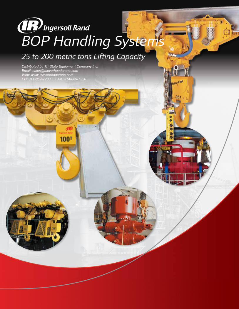
BOP Handling Systems25 to 200 metric tons Lifting CapacityDistributed by Tri-State Equipment Company Inc.Email: [email protected]: www.tsoverheadcrane.comPH: 314-869-7200 | FAX: 314-869-7226
1 2
ingersollrandproducts.com/lifting
1. BOP Handling Systems – Overview ..................................................................... 2
2. BOP Handling Systems – Selection Chart .............................................3
3. Hercu-Link™ Air BOP Handling Systems (50 to 200 tons Capacity) Standard Features and Options ........................................................................4
Specifications and Performance of Piston Motor Drive ..................................5
Model Driver ......................................................................................................6
Dimensions and Drawings .............................................................................. 11
4. Liftchain® BOP Handling Systems (25 to 200 tons Capacity) Standard Features and Options ........................................................................7
Liftchain® Air BOP Handling Systems
Specifications and Performance of Gear Motor Drive .............................8
Model Driver .......................................................................................... 10
Dimensions and Drawings ............................................................... 12-16
Liftchain® Hydraulic BOP Handling Systems
Specifications and Performance ...............................................................9
Model Driver .......................................................................................... 10
Dimensions and Drawings ............................................................... 12-16
5. Engineered Solutions BHS150M and BHS200M series ................................................................... 17
ULBS100LCA4 series (Ultra-low headroom design) .................................... 17
6. Contact Information Worldwide Locations .........................................................................Back Cover
Table of Contents
1 2
Certificate No. FM53539 Certificate No. QUAL/1991/309e
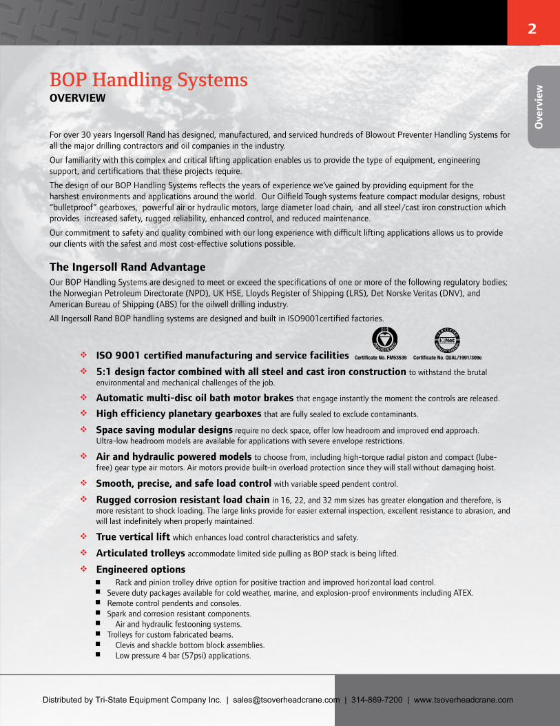
For over 30 years Ingersoll Rand has designed, manufactured, and serviced hundreds of Blowout Preventer Handling Systems for all the major drilling contractors and oil companies in the industry.
Our familiarity with this complex and critical lifting application enables us to provide the type of equipment, engineering support, and certifications that these projects require.
The design of our BOP Handling Systems reflects the years of experience we’ve gained by providing equipment for the harshest environments and applications around the world. Our Oilfield Tough systems feature compact modular designs, robust “bulletproof” gearboxes, powerful air or hydraulic motors, large diameter load chain, and all steel/cast iron construction which provides increased safety, rugged reliability, enhanced control, and reduced maintenance.
Our commitment to safety and quality combined with our long experience with difficult lifting applications allows us to provide our clients with the safest and most cost-effective solutions possible.
The Ingersoll Rand AdvantageOur BOP Handling Systems are designed to meet or exceed the specifications of one or more of the following regulatory bodies; the Norwegian Petroleum Directorate (NPD), UK HSE, Lloyds Register of Shipping (LRS), Det Norske Veritas (DNV), and American Bureau of Shipping (ABS) for the oilwell drilling industry.
All Ingersoll Rand BOP handling systems are designed and built in ISO9001certified factories.
ISO 9001 certified manufacturing and service facilities 5:1 design factor combined with all steel and cast iron construction to withstand the brutal
environmental and mechanical challenges of the job.
Automatic multi-disc oil bath motor brakes that engage instantly the moment the controls are released.
High efficiency planetary gearboxes that are fully sealed to exclude contaminants.
Space saving modular designs require no deck space, offer low headroom and improved end approach.Ultra-low headroom models are available for applications with severe envelope restrictions.
Air and hydraulic powered models to choose from, including high-torque radial piston and compact (lube-free) gear type air motors. Air motors provide built-in overload protection since they will stall without damaging hoist.
Smooth, precise, and safe load control with variable speed pendent control.
Rugged corrosion resistant load chain in 16, 22, and 32 mm sizes has greater elongation and therefore, ismore resistant to shock loading. The large links provide for easier external inspection, excellent resistance to abrasion, andwill last indefinitely when properly maintained.
True vertical lift which enhances load control characteristics and safety.
Articulated trolleys accommodate limited side pulling as BOP stack is being lifted.
Engineered options � Rack and pinion trolley drive option for positive traction and improved horizontal load control. � Severe duty packages available for cold weather, marine, and explosion-proof environments including ATEX. � Remote control pendents and consoles. � Spark and corrosion resistant components. � Air and hydraulic festooning systems. � Trolleys for custom fabricated beams. � Clevis and shackle bottom block assemblies. � Low pressure 4 bar (57psi) applications.
BOP Handling Systems OVERVIEW
Ove
rvie
w
Distributed by Tri-State Equipment Company Inc. | [email protected] | 314-869-7200 | www.tsoverheadcrane.com

3 4
ingersollrandproducts.com/lifting
**Rated capacity Model Number Number of Chain Falls Max. lifting speed Minimum Headroom(tons) per hoist m/min (ft/min) mm (in.)
Hercu-Link™ Air BOP Handling Systems (Piston motor drive)
50 BHS50M 2 1.2 (4) 1040 (40.94)
75 BHS75M 3 0.8 (2.5) 1243 (48.94)
100 BHS100M 4 0.6 (2) 1346 (53)
150 BHS150M 3 0.7 (2.5) –
200 BHS200M 4 0.6 (2) –
Liftchain® Air BOP Handling Systems (Gear motor drive)
25 BS25LCA2P 2 0.8 (2.63) 1128 (44.41)
30 BS30LCA3P 3 0.6 (1.97) 1242 (48.9)
36 BS36LCA3P 3 0.5 (1.64) 1242 (48.9)
40 BS40LCA4P 4 0.4 (1.30) 1290 (50.79)
50 BS50LCA2P 2 1.6 (5.25) 976 (38.42)
50 BS50LCA4P 4 0.4 (1.30) 1290 (50.79)
75 BS75LCA3P 3 1.1 (3.60) 1170 (46.06)
100 BS100LCA4P 4 0.8 (2.60) 1392 (54.8)
150 BS150LCA3P 3 0.4 (1.30) 1845 (72.64)
200 BS200LCA4P 4 0.3 (0.98) 1901 (74.84)
Liftchain® Hydraulic BOP Handling Systems
25 BS25LCH2P 2 2.8 (9.19) 1128 (44.41)
30 BS30LCH3P 3 1.9 (6.23) 1242 (48.9)
36 BS36LCH3P 3 1.86 (6.1) 1242 (48.9)
40 BS40LCH4P 4 1.35 (4.1) 1290 (50.79)
50 BS50LCH2P 2 2.27 (7.45) 976 (38.42)
50 BS50LCH4P 4 1.35 (4.1) 1290 (50.79)
75 BS75LCH3P 3 1.51 (4.95) 1170 (46.06)
100 BS100LCH4P 4 1.13 (3.7) 1392 (54.8)
150 BS150LCH3P 3 0.48 (1.57) 1845 (72.64)
200 BS200LCH4P 4 0.36 (1.18) 1901 (74.84)
BOP Handling Systems SELECTION CHART
**All BOP Handling Systems are comprised of two trolley-mounted hoists; each of which is rated at one-half the complete system capacity.
Selection Chart
3 4
BHS50M (50‑ton system) after storage of Blowout Preventer for periodic maintenance.
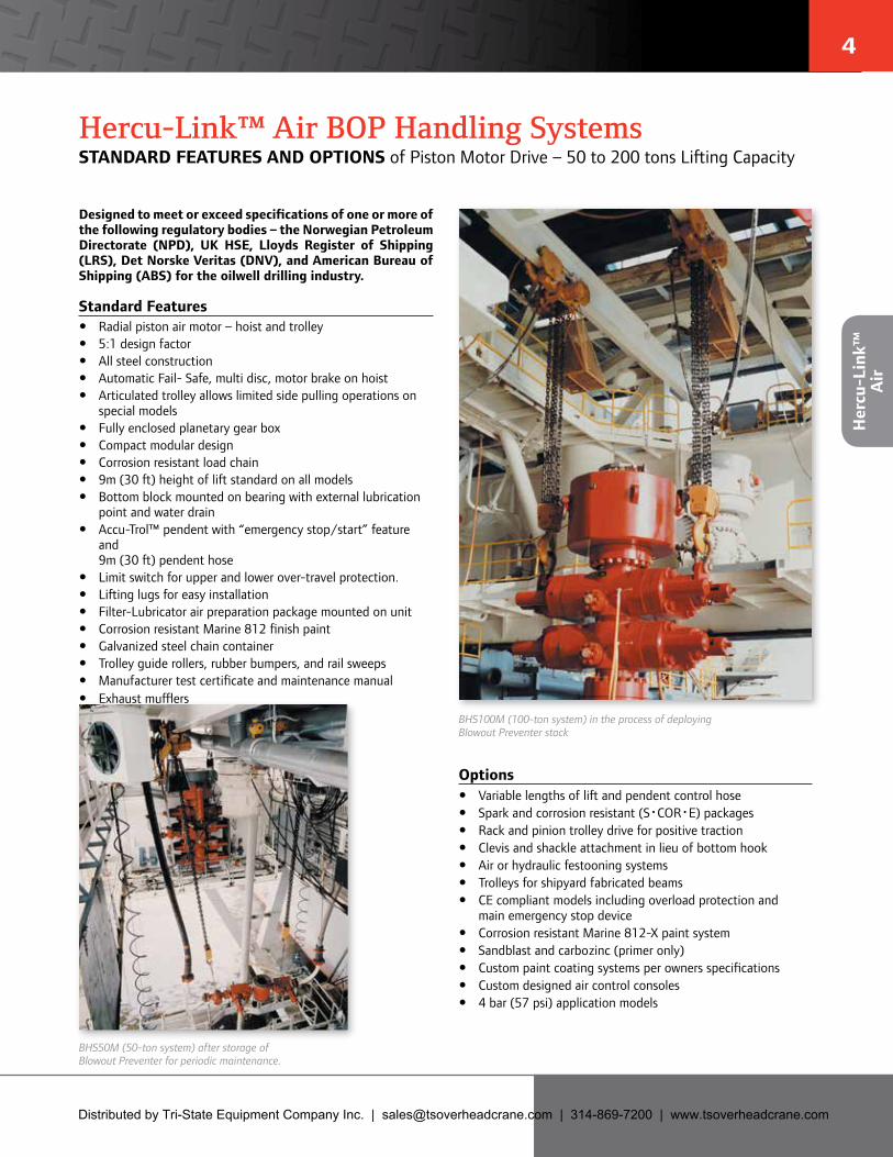
BHS100M (100‑ton system) in the process of deploying Blowout Preventer stack
Hercu-Link™ Air BOP Handling Systems STANDARD FEATURES AND OPTIONS of Piston Motor Drive – 50 to 200 tons Lifting Capacity
Designed to meet or exceed specifications of one or more of the following regulatory bodies – the Norwegian Petroleum Directorate (NPD), UK HSE, Lloyds Register of Shipping (LRS), Det Norske Veritas (DNV), and American Bureau of Shipping (ABS) for the oilwell drilling industry.
Standard Features y Radial piston air motor – hoist and trolley y 5:1 design factor y All steel construction y Automatic Fail- Safe, multi disc, motor brake on hoist y Articulated trolley allows limited side pulling operations on
special models y Fully enclosed planetary gear box y Compact modular design y Corrosion resistant load chain y 9m (30 ft) height of lift standard on all models y Bottom block mounted on bearing with external lubrication
point and water drain y Accu-Trol™ pendent with “emergency stop/start” feature
and 9m (30 ft) pendent hose
y Limit switch for upper and lower over-travel protection. y Lifting lugs for easy installation y Filter-Lubricator air preparation package mounted on unit y Corrosion resistant Marine 812 finish paint y Galvanized steel chain container y Trolley guide rollers, rubber bumpers, and rail sweeps y Manufacturer test certificate and maintenance manual y Exhaust mufflers
Options y Variable lengths of lift and pendent control hose y Spark and corrosion resistant (S•COR•E) packages y Rack and pinion trolley drive for positive traction y Clevis and shackle attachment in lieu of bottom hook y Air or hydraulic festooning systems y Trolleys for shipyard fabricated beams y CE compliant models including overload protection and
main emergency stop device y Corrosion resistant Marine 812-X paint system y Sandblast and carbozinc (primer only) y Custom paint coating systems per owners specifications y Custom designed air control consoles y 4 bar (57 psi) application models
Her
cu-L
ink™
A
ir
Distributed by Tri-State Equipment Company Inc. | [email protected] | 314-869-7200 | www.tsoverheadcrane.com
5 6
ingersollrandproducts.com/lifting
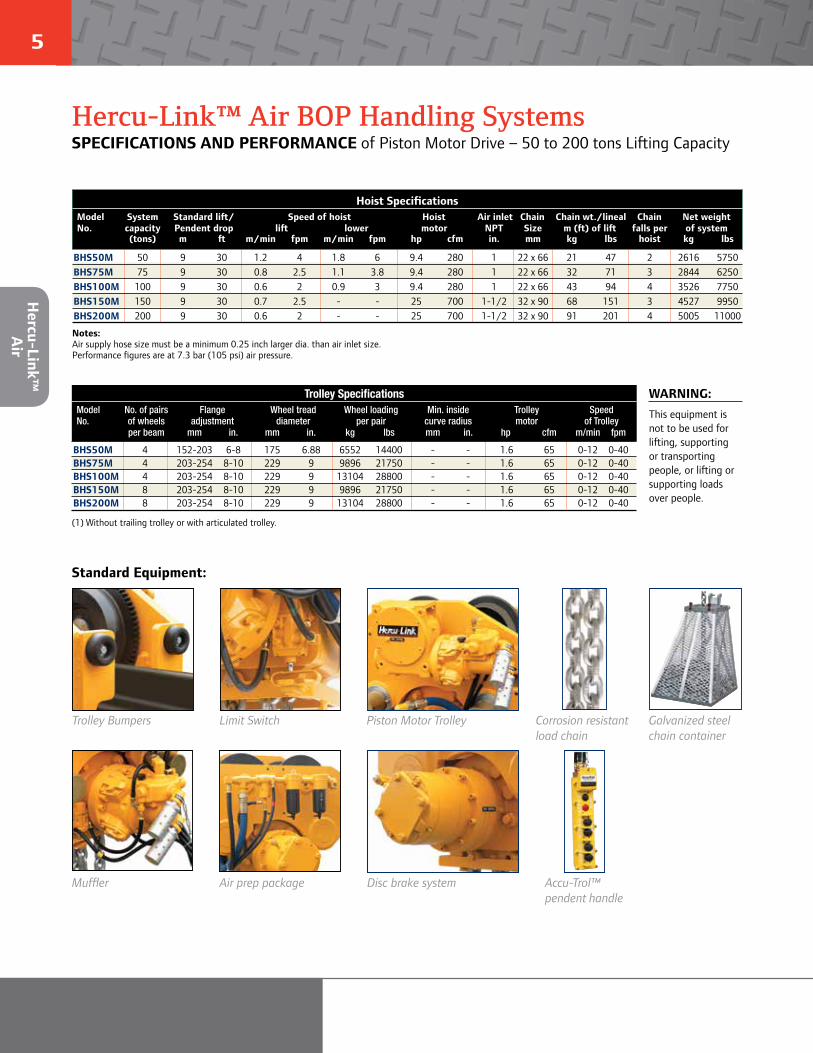
Standard Equipment:
Trolley Bumpers
Muffler
Limit Switch
Air prep package
Piston Motor Trolley
Disc brake system Accu‑Trol™ pendent handle
Corrosion resistant load chain
Galvanized steel chain container
Hercu-Link™ Air BOP Handling SystemsSPECIFICATIONS AND PERFORMANCE of Piston Motor Drive – 50 to 200 tons Lifting Capacity
WARNING:This equipment is not to be used for lifting, supporting or transporting people, or lifting or supporting loads over people.
Hoist SpecificationsModel System Standard lift/ Speed of hoist Hoist Air inlet Chain Chain wt./lineal Chain Net weightNo. capacity Pendent drop lift lower motor NPT Size m (ft) of lift falls per of system
(tons) m ft m/min fpm m/min fpm hp cfm in. mm kg lbs hoist kg lbs
BHS50M 50 9 30 1.2 4 1.8 6 9.4 280 1 22 x 66 21 47 2 2616 5750BHS75M 75 9 30 0.8 2.5 1.1 3.8 9.4 280 1 22 x 66 32 71 3 2844 6250BHS100M 100 9 30 0.6 2 0.9 3 9.4 280 1 22 x 66 43 94 4 3526 7750BHS150M 150 9 30 0.7 2.5 - - 25 700 1-1/2 32 x 90 68 151 3 4527 9950 BHS200M 200 9 30 0.6 2 - - 25 700 1-1/2 32 x 90 91 201 4 5005 11000
Notes: Air supply hose size must be a minimum 0.25 inch larger dia. than air inlet size. Performance figures are at 7.3 bar (105 psi) air pressure.
Trolley SpecificationsModel No. of pairs Flange Wheel tread Wheel loading Min. inside Trolley SpeedNo. of wheels adjustment diameter per pair curve radius motor of Trolley
per beam mm in. mm in. kg lbs mm in. hp cfm m/min fpm
BHS50M 4 152-203 6-8 175 6.88 6552 14400 - - 1.6 65 0-12 0-40BHS75M 4 203-254 8-10 229 9 9896 21750 - - 1.6 65 0-12 0-40BHS100M 4 203-254 8-10 229 9 13104 28800 - - 1.6 65 0-12 0-40BHS150M 8 203-254 8-10 229 9 9896 21750 - - 1.6 65 0-12 0-40BHS200M 8 203-254 8-10 229 9 13104 28800 - - 1.6 65 0-12 0-40
(1) Without trailing trolley or with articulated trolley.
Hercu-Link™
A
ir
5 6
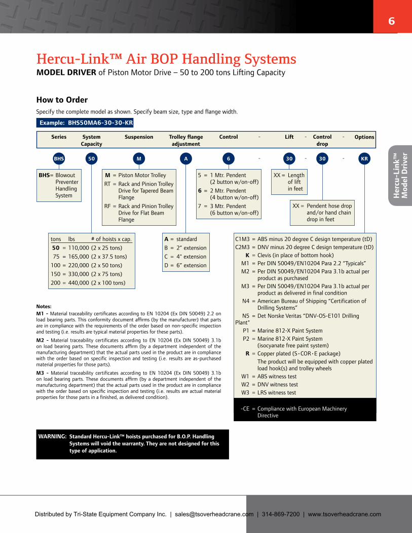
How to OrderSpecify the complete model as shown. Specify beam size, type and flange width.
Example: BHS50MA6-30-30-KR
BHS = Blowout Preventer Handling System
M = Piston Motor Trolley RT = Rack and Pinion Trolley
Drive for Tapered Beam Flange
RF = Rack and Pinion Trolley Drive for Flat Beam Flange
A = standardB = 2” extensionC = 4" extensionD = 6” extension
5 = 1 Mtr. Pendent (2 button w/on-off)
6 = 2 Mtr. Pendent (4 button w/on-off)
7 = 3 Mtr. Pendent (6 button w/on-off)
XX = Length of lift in feet
tons lbs # of hoists x cap. 50 = 110,000 (2 x 25 tons) 75 = 165,000 (2 x 37.5 tons) 100 = 220,000 (2 x 50 tons)150 = 330,000 (2 x 75 tons) 200 = 440,000 (2 x 100 tons)
WARNING: Standard Hercu-Link™ hoists purchased for B.O.P. Handling Systems will void the warranty. They are not designed for this type of application.
XX = Pendent hose drop and/or hand chain drop in feet
KR30306AM50BHS
C1M3 = ABS minus 20 degree C design temperature (tD) C2M3 = DNV minus 20 degree C design temperature (tD)
K = Clevis (in place of bottom hook)M1 = Per DIN 50049/EN10204 Para 2.2 “Typicals”M2 = Per DIN 50049/EN10204 Para 3.1b actual per
product as purchasedM3 = Per DIN 50049/EN10204 Para 3.1b actual per
product as delivered in final conditionN4 = American Bureau of Shipping “Certification of
Drilling Systems” N5 = Det Norske Veritas “DNV-OS-E101 Drilling Plant"
P1 = Marine 812-X Paint SystemP2 = Marine 812-X Paint System
(isocyanate free paint system)R = Copper plated (S•COR•E package)
The product will be equipped with copper plated load hook(s) and trolley wheels
W1 = ABS witness testW2 = DNV witness testW3 = LRS witness testW4 = Customer witness test-CE = Compliance with European Machinery
Directive
Notes:M1 - Material traceability certificates according to EN 10204 (Ex DIN 50049) 2.2 on load bearing parts. This conformity document affirms (by the manufacturer) that parts are in compliance with the requirements of the order based on non-specific inspection and testing (i.e. results are typical material properties for these parts).
M2 - Material traceability certificates according to EN 10204 (Ex DIN 50049) 3.1b on load bearing parts. These documents affirm (by a department independent of the manufacturing department) that the actual parts used in the product are in compliance with the order based on specific inspection and testing (i.e. results are as-purchased material properties for those parts).
M3 - Material traceability certificates according to EN 10204 (Ex DIN 50049) 3.1b on load bearing parts. These documents affirm (by a department independent of the manufacturing department) that the actual parts used in the product are in compliance with the order based on specific inspection and testing (i.e. results are actual material properties for those parts in a finished, as delivered condition).
Hercu-Link™ Air BOP Handling SystemsMODEL DRIVER of Piston Motor Drive – 50 to 200 tons Lifting Capacity
Series SystemCapacity
Suspension Trolley flangeadjustment
Control -
-
Lift OptionsControldrop
-
-
-
-
Her
cu-L
ink™
M
odel
Dri
ver
Distributed by Tri-State Equipment Company Inc. | [email protected] | 314-869-7200 | www.tsoverheadcrane.com
7 8
ingersollrandproducts.com/lifting
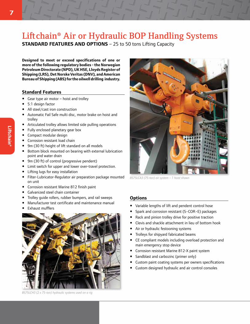
Designed to meet or exceed specifications of one or more of the following regulatory bodies - the Norwegian Petroleum Directorate (NPD), UK HSE, Lloyds Register of Shipping (LRS), Det Norske Veritas (DNV), and American Bureau of Shipping (ABS) for the oilwell drilling industry.
Standard Features y Gear type air motor – hoist and trolley y 5:1 design factor y All steel/cast iron construction y Automatic Fail Safe multi disc, motor brake on hoist and
trolley y Articulated trolley allows limited side pulling operations y Fully enclosed planetary gear box y Compact modular design y Corrosion resistant load chain y 9m (30 ft) height of lift standard on all models y Bottom block mounted on bearing with external lubrication
point and water drain y 9m (30 ft) of control (progressive pendent) y Limit switch for upper and lower over-travel protection. y Lifting lugs for easy installation y Filter-Lubricator-Regulator air preparation package mounted
on unit y Corrosion resistant Marine 812 finish paint y Galvanized steel chain container y Trolley guide rollers, rubber bumpers, and rail sweeps y Manufacturer test certificate and maintenance manual y Exhaust mufflers
Options
y Variable lengths of lift and pendent control hose y Spark and corrosion resistant (S•COR•E) packages y Rack and pinion trolley drive for positive traction y Clevis and shackle attachment in lieu of bottom hook y Air or hydraulic festooning systems y Trolleys for shipyard fabricated beams y CE compliant models including overload protection and
main emergency stop device y Corrosion resistant Marine 812-X paint system y Sandblast and carbozinc (primer only) y Custom paint coating systems per owners specifications y Custom designed hydraulic and air control consoles
BS75LCH3 (2 x 75‑ton) hydraulic systems used on a rig
BS75LCA3 (75‑ton) air system – 1 hoist shown
Liftchain® Air or Hydraulic BOP Handling SystemsSTANDARD FEATURES AND OPTIONS – 25 to 50 tons Lifting Capacity
Liftchain®

7 8
Hoist SpecificationsModel System Standard lift/ Speed of hoist Hoist Air inlet Chain Chain wt./lineal Chain Net weightNo. capacity Pendent drop lift lower motor BSP Size m (ft) of lift falls per of system
(tons) m ft m/min fpm m/min fpm hp cfm in. mm kg lbs hoist kg lbs
BS25LCA2P 25 9 30 0.8 2.63 1.50 4.92 4 163 3/4 16 x 45 11 25 2 800 1760
BS30LCA3P 30 9 30 0.6 1.97 1.00 3.28 4 163 3/4 16 x 45 17 38 3 970 2134
BS36LCA3P 36 9 30 0.5 1.64 1.00 3.28 4 163 3/4 16 x 45 17 38 3 970 2134
BS40LCA4P 40 9 30 0.4 1.30 0.75 2.46 4 163 3/4 16 x 45 23 50 4 1040 2288
BS50LCA2P 50 9 30 1.6 5.25 2.50 8.20 10 406 1"1/4 22 x 66 21 47 2 1130 2486
BS50LCA4P 50 9 30 0.4 1.30 0.75 2.46 4 163 3/4 16 x 45 23 50 4 1040 2288
BS75LCA3P 75 9 30 1.1 3.60 1.70 5.58 10 406 1"1/4 22 x 66 32 71 3 4000 8800
BS100LCA4P 100 9 30 0.8 2.60 0.90 2.95 10 406 1"1/4 22 x 66 43 94 4 4400 9680
BS150LCA3P 150 9 30 0.4 1.30 0.48 1.57 10 406 1"1/4 32 x 90 68 151 3 9440 20768
BS200LCA4P 200 9 30 0.3 0.98 0.35 1.16 10 406 1"1/4 32 x 90 91 201 4 9990 21978
Notes: Air supply hose size must be a minimum 0.25 inch larger dia. than air inlet size.
Trolley SpecificationsModel No. of pairs Flange Wheel tread Wheel loading Min. inside Trolley SpeedNo. of wheels adjustment diameter per pair curve radius motor of Trolley
per beam mm in. mm in. kg lbs mm in. hp cfm m/min fpm
BS25LCA2P 2 131-310 5-12 160 6.30 6250 13750 3 118 2 81 12 39
BS30LCA3P 2 131-310 5-12 225 8.86 7500 16500 5 197 2 81 12 39
BS36LCA3P 2 131-310 5-12 225 8.86 9000 19800 5 197 2 81 12 39
BS40LCA4P 2 131-310 5-12 225 8.86 12500 27500 5 197 2 81 12 39
BS50LCA2P 4 160-310 6-12 160 6.30 6250 13750 105 4134 2 (Qty 2) 81 (Qty 2) 12 39
BS50LCA4P 2 131-310 5-12 225 8.86 12500 27500 5 197 2 81 12 39
BS75LCA3P 4 160-310 6-12 225 8.86 9375 20625 105 4134 2 (Qty 2) 81 (Qty 2) 12 39
BS100LCA4P 4 160-310 6-12 225 8.86 12500 27500 105 4134 2 (Qty 2) 81 (Qty 2) 12 39
BS150LCA3P 8 160-310 6-12 225 8.86 9375 20625 130 5118 2 (Qty 4) 81 (Qty 4) 12 39
BS200LCA4P 8 160-310 6-12 225 8.86 12500 27500 130 5118 2 (Qty 4) 81 (Qty 4) 12 39
WARNING:This equipment is not to be used for lifting, supporting or transporting people, or lifting or supporting loads over people.
Liftchain® 200‑ton BOP Handling System(1 hoist shown)
Liftchain® Air BOP Handling SystemsSPECIFICATIONS AND PERFORMANCE of Gear Motor Drive – 25 to 50 tons Lifting Capacity
Lift
chai
n®
Air

9 10
ingersollrandproducts.com/lifting
Liftchain® Hydraulic BOP Handling SystemsSPECIFICATIONS AND PERFORMANCE – 25 to 200 tons Lifting Capacity
Trolley SpecificationsModel No. of pairs Flange Wheel tread Wheel loading Min. inside Speed Working Calibration NominalNo. of wheels adjustment diameter per pair curve radius of Trolley Pressure Pressure Flow
per beam mm in. mm in. kg lbs mm in. m/min fpm bar psi bar psi l/min gpm
BS25LCH2P 2 131-310 5-12 160 6.3 6250 13750 3 118.1 15 49 140 2030 165 2393 10 3
BS30LCH3P 2 131-310 5-12 225 8.86 7500 16500 5 196.85 15 49 140 2030 175 2538 10 3
BS36LCH3P 2 131-310 5-12 225 8.86 9000 19800 5 196.85 15 49 140 2030 175 2538 10 3
BS40LCH4P 2 131-310 5-12 225 8.86 12500 27500 5 196.85 15 49 140 2030 175 2538 10 3
BS50LCH2P 4 160-310 6-12 160 6.3 6250 13750 105 4134 15 49 150 2175 210 3045 10 3
BS50LCH4P 2 131-310 5-12 225 8.86 12500 27500 5 196.85 15 49 140 2030 175 2538 10 3
BS75LCH3P 4 160-310 6-12 225 8.86 9375 20625 105 4134 15 49 150 2175 210 3045 10 3
BS100LCH4P 4 160-310 6-12 225 8.86 12500 27500 105 4134 15 49 150 2175 210 3045 10 3
BS150LCH3P 8 160-310 6-12 225 8.86 9375 20625 130 5118 15 49 200 2900 210 3045 35 9
BS200LCH4P 8 160-310 6-12 225 8.86 12500 27500 130 5118 15 49 220 3190 250 3625 35 9
LCH250DIRN25‑ton hydraulic hoist/trolley combination
Hydraulic control console allowing the control of four hoist/trolley combinations
Hoist SpecificationsModel System Standard lift/ Speed of hoist Air inlet Chain Chain wt./lineal Chain Net weight Working Calibration NominalNo. capacity Pendent drop lift lower BSP Size m (ft) of lift falls per of system Pressure Pressure Flow
(tons) m ft m/min fpm m/min fpm in. mm kg lbs hoist kg lbs bar psi bar psi l/min gpm
BS25LCH2P 25 9 30 2.8 9.19 2.8 9.19 1/2 16 x 45 11.4 25.1 2 770 1694 140 2030 175 2538 48 13
BS30LCH3P 30 9 30 1.9 6.23 1.9 6.23 1/2 16 x 45 17.1 37.7 3 970 2134 140 2030 175 2538 48 13
BS36LCH3P 36 9 30 1.86 6.1 1.86 6.1 1/2 16 x 45 17.1 37.7 3 970 2134 140 2030 175 2538 48 13
BS40LCH4P 40 9 30 1.35 4.1 1.35 4.1 1/2 16 x 45 22.8 50.3 4 1090 2398 140 2030 175 2538 48 13
BS50LCH2P 50 9 30 2.27 7.45 2.27 7.45 3/4 22 x 66 21.4 47.2 2 2130 4686 175 2538 200 2900 50 13
BS50LCH4P 50 9 30 1.35 4.1 1.35 4.1 1/2 16 x 45 22.8 50.3 4 1090 2398 140 2030 175 2538 48 13
BS75LCH3P 75 9 30 1.51 4.95 1.51 4.95 3/4 22 x 66 32.1 70.8 3 2990 6578 180 2610 210 3045 50 13
BS100LCH4P 100 9 30 1.13 3.7 1.13 3.7 3/4 22 x 66 42.8 94.3 4 3460 7612 177 2567 210 3045 50 13
BS150LCH3P 150 9 30 0.48 1.57 0.48 1.57 3/4 32 x 90 68.4 150.8 3 9880 21736 140 2030 210 3045 35 9
BS200LCH4P 200 9 30 0.36 1.18 0.36 1.18 3/4 32 x 90 91.2 201 4 12390 27258 220 3190 240 3480 35 9
Liftchain®
Hydraulic
9 10
Liftchain® Air or Hydraulic BOP Handling SystemsMODEL DRIVER – 25 to 200 tons Lifting Capacity
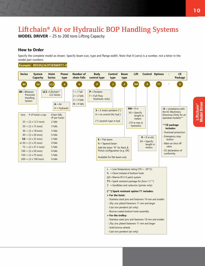
How to OrderSpecify the complete model as shown. Specify beam size, type and flange width. Note that 0 (zero) is a number, not a letter in the model part numbers.
Example: BS50LCA2P3E9M9T1-E
tons # of hoists x cap. Chain falls (# per hoist)
25 = (2 x 12.5 tons) 2 falls
30 = (2 x 15 tons) 3 falls
36 = (2 x 18 tons) 3 falls
40 = (2 x 20 tons) 4 falls
50 = (2 x 25 tons) 2 falls
or 50 = (2 x 25 tons) 4 falls
75 = (2 x 37.5 tons) 3 falls
100 = (2 x 50 tons) 4 falls
150 = (2 x 75 tons) 3 falls
200 = (2 x 100 tons) 4 falls
Series Hoist Series
Power type
Beam type
-
-BS LC2
Lift Control Options CE Package
E50 A
A = Air
H = Hydraulic
Number of chain falls
1 = 1 fall
2 = 2 falls
3 = 3 falls
4 = 4 falls
LC2 = Liftchain® LC2 Series
3
E = Flat beam
N = Tapered beam
Add the letter "R" for Rack & Pinion configuration (e.g. ER)
Available for flat beam only
9 = 9 m std.
XX = Specify length in meters
3 = 2 motor pendent (*)
0 = no control (for hyd.)
(*) Joystick type in hyd.
9M = 9 m
XX = Specify length in meters
(10 m max in hydraulic)
-E = compliance with the EC Machinery Directives (Only for air operated models)**
** CE packageincludes:
- Overload protection
- Emergency stop button
- Main air shut off valve
- CE declaration of conformity
BS = Blowout Preventer Handling System
SystemCapacity
Body control type
P = Pendent
F = Full Flow (hydraulic only)
Controltype
L = Low Temperature rating (TD = -20°C)
N = Clevis instead of bottom hook
QZ = Marine 812-X paint system
T1 = Spark resistant package for Zone 1 (**)
Z = Sandblast and carbozinc (primer only)
(**) Spark resistant option T1 includes:> For the hoist: - Stainless steel pins and fasteners 10 mm and smaller
- 20µ zinc plated fasteners 11 mm and larger
- Cast iron pendent (air only)
- Bronze coated bottom hook assembly
> For the trolley: - Stainless steel pins and fasteners 10 mm and smaller
- 20µ zinc plated fasteners 11 mm and larger
- Solid bronze wheels
- Cast iron pendent (air only)
T19M 9EP4
Lift
chai
n®
Mod
el D
river
11 12
ingersollrandproducts.com/lifting
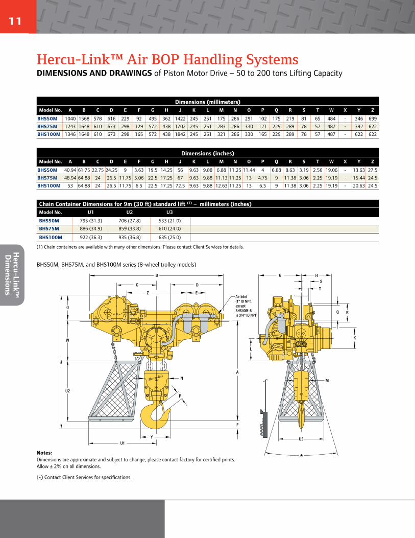
Dimensions (millimeters)Model No. A B C D E F G H J K L M N O P Q R S T W X Y Z
BHS50M 1040 1568 578 616 229 92 495 362 1422 245 251 175 286 291 102 175 219 81 65 484 - 346 699
BHS75M 1243 1648 610 673 298 129 572 438 1702 245 251 283 286 330 121 229 289 78 57 487 - 392 622
BHS100M 1346 1648 610 673 298 165 572 438 1842 245 251 321 286 330 165 229 289 78 57 487 - 622 622
Dimensions (inches)Model No. A B C D E F G H J K L M N O P Q R S T W X Y Z
BHS50M 40.94 61.75 22.75 24.25 9 3.63 19.5 14.25 56 9.63 9.88 6.88 11.25 11.44 4 6.88 8.63 3.19 2.56 19.06 - 13.63 27.5
BHS75M 48.94 64.88 24 26.5 11.75 5.06 22.5 17.25 67 9.63 9.88 11.13 11.25 13 4.75 9 11.38 3.06 2.25 19.19 - 15.44 24.5
BHS100M 53 64.88 24 26.5 11.75 6.5 22.5 17.25 72.5 9.63 9.88 12.63 11.25 13 6.5 9 11.38 3.06 2.25 19.19 - 20.63 24.5
G HS
T
Q R
K
L
M
A
F
B
C D
EZ
O
W
J
N
P
Y
Air Inlet(1" ID NPT, exceptBHS40M-8 is 3/4" ID NPT)
U1
U2
U3
*
BHS50M, BHS75M, and BHS100M series (8-wheel trolley models)
Hercu-Link™ Air BOP Handling SystemsDIMENSIONS AND DRAWINGS of Piston Motor Drive – 50 to 200 tons Lifting Capacity
Notes: Dimensions are approximate and subject to change, please contact factory for certified prints. Allow ± 2% on all dimensions.
(*) Contact Client Services for specifications.
Chain Container Dimensions for 9m (30 ft) standard lift (1) – millimeters (inches)Model No. U1 U2 U3
BHS50M 795 (31.3) 706 (27.8) 533 (21.0)
BHS75M 886 (34.9) 859 (33.8) 610 (24.0)
BHS100M 922 (36.3) 935 (36.8) 635 (25.0)
(1) Chain containers are available with many other dimensions. Please contact Client Services for details. Hercu-Link™
D
imensions
11 12
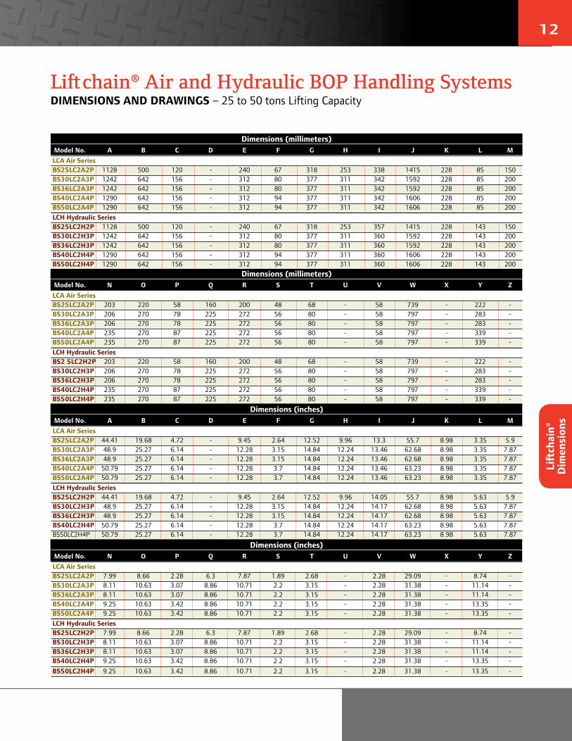
Liftchain® Air and Hydraulic BOP Handling SystemsDIMENSIONS AND DRAWINGS – 25 to 50 tons Lifting Capacity
Dimensions (millimeters)Model No. A B C D E F G H I J K L MLCA Air SeriesBS25LC2A2P 1128 500 120 - 240 67 318 253 338 1415 228 85 150 BS30LC2A3P 1242 642 156 - 312 80 377 311 342 1592 228 85 200 BS36LC2A3P 1242 642 156 - 312 80 377 311 342 1592 228 85 200 BS40LC2A4P 1290 642 156 - 312 94 377 311 342 1606 228 85 200BS50LC2A4P 1290 642 156 - 312 94 377 311 342 1606 228 85 200LCH Hydraulic SeriesBS25LC2H2P 1128 500 120 - 240 67 318 253 357 1415 228 143 150 BS30LC2H3P 1242 642 156 - 312 80 377 311 360 1592 228 143 200 BS36LC2H3P 1242 642 156 - 312 80 377 311 360 1592 228 143 200 BS40LC2H4P 1290 642 156 - 312 94 377 311 360 1606 228 143 200BS50LC2H4P 1290 642 156 - 312 94 377 311 360 1606 228 143 200
Dimensions (millimeters)Model No. N O P Q R S T U V W X Y ZLCA Air SeriesBS25LC2A2P 203 220 58 160 200 48 68 - 58 739 - 222 -BS30LC2A3P 206 270 78 225 272 56 80 - 58 797 - 283 -BS36LC2A3P 206 270 78 225 272 56 80 - 58 797 - 283 -BS40LC2A4P 235 270 87 225 272 56 80 - 58 797 - 339 -BS50LC2A4P 235 270 87 225 272 56 80 - 58 797 - 339 -LCH Hydraulic SeriesBS2 5LC2H2P 203 220 58 160 200 48 68 - 58 739 - 222 -BS30LC2H3P 206 270 78 225 272 56 80 - 58 797 - 283 -BS36LC2H3P 206 270 78 225 272 56 80 - 58 797 - 283 -BS40LC2H4P 235 270 87 225 272 56 80 - 58 797 - 339 -BS50LC2H4P 235 270 87 225 272 56 80 - 58 797 - 339 -
Dimensions (inches)Model No. A B C D E F G H I J K L MLCA Air SeriesBS25LC2A2P 44.41 19.68 4.72 - 9.45 2.64 12.52 9.96 13.3 55.7 8.98 3.35 5.9 BS30LC2A3P 48.9 25.27 6.14 - 12.28 3.15 14.84 12.24 13.46 62.68 8.98 3.35 7.87 BS36LC2A3P 48.9 25.27 6.14 - 12.28 3.15 14.84 12.24 13.46 62.68 8.98 3.35 7.87 BS40LC2A4P 50.79 25.27 6.14 - 12.28 3.7 14.84 12.24 13.46 63.23 8.98 3.35 7.87BS50LC2A4P 50.79 25.27 6.14 - 12.28 3.7 14.84 12.24 13.46 63.23 8.98 3.35 7.87LCH Hydraulic SeriesBS25LC2H2P 44.41 19.68 4.72 - 9.45 2.64 12.52 9.96 14.05 55.7 8.98 5.63 5.9 BS30LC2H3P 48.9 25.27 6.14 - 12.28 3.15 14.84 12.24 14.17 62.68 8.98 5.63 7.87 BS36LC2H3P 48.9 25.27 6.14 - 12.28 3.15 14.84 12.24 14.17 62.68 8.98 5.63 7.87BS40LC2H4P 50.79 25.27 6.14 - 12.28 3.7 14.84 12.24 14.17 63.23 8.98 5.63 7.87BS50LC2H4P 50.79 25.27 6.14 - 12.28 3.7 14.84 12.24 14.17 63.23 8.98 5.63 7.87
Dimensions (inches)Model No. N O P Q R S T U V W X Y ZLCA Air SeriesBS25LC2A2P 7.99 8.66 2.28 6.3 7.87 1.89 2.68 - 2.28 29.09 - 8.74 -BS30LC2A3P 8.11 10.63 3.07 8.86 10.71 2.2 3.15 - 2.28 31.38 - 11.14 -BS36LC2A3P 8.11 10.63 3.07 8.86 10.71 2.2 3.15 - 2.28 31.38 - 11.14 -BS40LC2A4P 9.25 10.63 3.42 8.86 10.71 2.2 3.15 - 2.28 31.38 - 13.35 -BS50LC2A4P 9.25 10.63 3.42 8.86 10.71 2.2 3.15 - 2.28 31.38 - 13.35 -LCH Hydraulic SeriesBS25LC2H2P 7.99 8.66 2.28 6.3 7.87 1.89 2.68 - 2.28 29.09 - 8.74 -BS30LC2H3P 8.11 10.63 3.07 8.86 10.71 2.2 3.15 - 2.28 31.38 - 11.14 -BS36LC2H3P 8.11 10.63 3.07 8.86 10.71 2.2 3.15 - 2.28 31.38 - 11.14 -BS40LC2H4P 9.25 10.63 3.42 8.86 10.71 2.2 3.15 - 2.28 31.38 - 13.35 -BS50LC2H4P 9.25 10.63 3.42 8.86 10.71 2.2 3.15 - 2.28 31.38 - 13.35 -
Lift
chai
n®
Dim
ensi
ons

13 14
ingersollrandproducts.com/lifting
Liftchain® Air and Hydraulic BOP Handling SystemsDIMENSIONS AND DRAWINGS – 25 to 50 tons Lifting Capacity
BS25LC2_2 - BS30LC2_3 - BS36LC2_3 - BS40LC2_4 - BS50LC2_4 series
Chain Container Dimensions for 9m (30 ft) standard lift (1) – millimeters (inches)Model No. U1 U2 U3
BS25LC2_2P 565 (22.24) 720 (28.35) 400 (15.75)
BS30LC2_3P 565 (22.24) 720 (28.35) 400 (15.75)
BS36LC2_3P 565 (22.24) 720 (28.35) 400 (15.75)
BS40LC2_4P 565 (22.24) 720 (28.35) 550 (21.65)
BS50LC2_4P 565 (22.24) 720 (28.35) 550 (21.65)
(1) Chain containers are available with many other dimensions. Please contact Client Services for details.
V V
N
H
A
G
P
Q R
L
TS
F
Y
J
U1
U2W
C
E
B
O
U3
K
I
M
*
4 leversremote control
OST P
Air inlet 3/4" ID BSP
Notes: Dimensions are approximate and subject to change, please contact factory for certified prints. Allow ± 2% on all dimensions.
(*) Contact Client Services for specifications.
Liftchain®
Dimensions

13 14
Liftchain® Air and Hydraulic BOP Handling SystemsDIMENSIONS AND DRAWINGS – 25 to 200 tons Lifting Capacity
Dimensions (millimeters)Model No. A B C D E F G H I J K L M
Liftchain® Air Series
BS50LCA2P 976 1240 370 500 240 97 492 367 342 1293 223 196 190
BS75LCA3P 1170 1552 455 642 312 132 547 472 360 1572 223 196 278
BS100LCA4P 1392 1552 455 642 312 152 547 472 360 1662 223 196 281
Liftchain® Hydraulic Series
BS50LCH2P 976 1240 370 500 240 97 446 265 357 1293 298 137 190
BS75LCH3P 1170 1552 455 642 312 132 500 372 360 1572 298 137 278
BS100LCH4P 1392 1552 455 642 312 152 500 372 360 1662 298 137 281
Dimensions (millimeters)Model No. N O P Q R S T U V W X Y Z
Liftchain® Air Series
BS50LCA2P 276 220 82 160 200 48 68 - 58 436 - 339 500
BS75LCA3P 298 270 103 225 272 56 80 - 58 494 - 384 598
BS100LCA4P 352 270 118 225 272 56 80 - 58 494 - 384 598
Liftchain® Hydraulic Series
BS50LCH2P 276 220 82 160 200 48 68 - 58 436 - 339 500
BS75LCH3P 298 270 103 225 272 56 80 - 58 494 - 384 598
BS100LCH4P 352 270 118 225 272 56 80 - 58 494 - 384 598
Dimensions (inches)Model No. A B C D E F G H I J K L M
Liftchain® Air Series
BS50LCA2P 38.42 48.82 14.57 19.68 9.45 3.82 19.37 14.45 13.46 50.9 8.78 7.72 7.48
BS75LCA3P 46.06 61.1 17.91 25.28 12.28 5.2 21.5 18.58 14.17 61.89 8.78 7.72 10.94
BS100LCA4P 54.8 61.1 17.91 25.28 12.28 5.98 21.5 18.58 14.17 65.43 8.78 7.72 11.06
Liftchain® Hydraulic Series
BS50LCH2P 38.42 48.82 14.57 19.68 9.45 3.82 17.56 10.43 14.05 50.9 11.73 5.39 7.48
BS75LCH3P 46.06 61.1 17.91 25.28 12.28 5.2 19.68 14.64 14.17 61.89 11.73 5.39 10.94
BS100LCH4P 54.8 61.1 17.91 25.28 12.28 5.98 19.68 14.64 14.17 65.43 11.73 5.39 11.06
Dimensions (inches)Model No. N O P Q R S T U V W X Y Z
Liftchain® Air Series
BS50LCA2P 10.87 8.66 3.23 6.3 7.87 1.89 2.68 - 2.28 17.16 - 13.35 19.68
BS75LCA3P 11.73 10.63 4.05 8.86 10.71 2.2 3.15 - 2.28 19.45 - 15.12 23.54
BS100LCA4P 11.73 10.63 4.65 8.86 10.71 2.2 3.15 - 2.28 19.45 - 15.12 23.54
Liftchain® Hydraulic Series
BS50LCH2P 10.87 8.66 3.23 6.3 7.87 1.89 2.68 - 2.28 17.16 - 13.35 19.68
BS75LCH3P 11.73 10.63 4.05 8.86 10.71 2.2 3.15 - 2.28 19.45 - 15.12 23.54
BS100LCH4P 11.73 10.63 4.65 8.86 10.71 2.2 3.15 - 2.28 19.45 - 15.12 23.54
Lift
chai
n®
Dim
ensi
ons
15 16
ingersollrandproducts.com/lifting
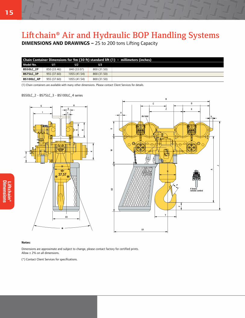
Liftchain® Air and Hydraulic BOP Handling SystemsDIMENSIONS AND DRAWINGS – 25 to 200 tons Lifting Capacity
BS50LC_2 - BS75LC_3 - BS100LC_4 series
U3
U1
37,5T
M
H
F
P
A
V
Y
T
S
Q R
L
J
I
G
K
U2
*
N
Z E
V
B
C D
OW
remote control4 levers
PTS O
Air Inlet
Chain Container Dimensions for 9m (30 ft) standard lift (1) – millimeters (inches)Model No. U1 U2 U3
BS50LC_2P 850 (33.46) 840 (33.07) 800 (31.50)
BS75LC_3P 955 (37.60) 1055 (41.54) 800 (31.50)
BS100LC_4P 955 (37.60) 1055 (41.54) 800 (31.50)
(1) Chain containers are available with many other dimensions. Please contact Client Services for details.
Notes:
Dimensions are approximate and subject to change, please contact factory for certified prints. Allow ± 2% on all dimensions.
(*) Contact Client Services for specifications.
Liftchain®
Dimensions
15 16
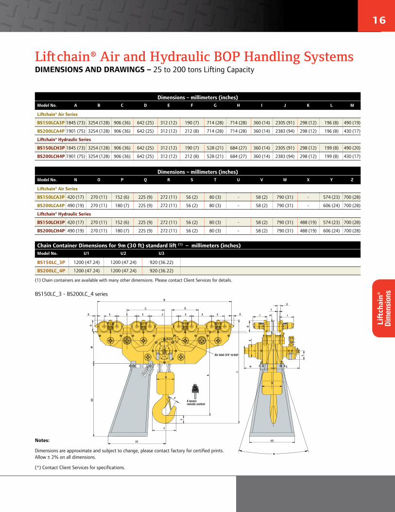
Liftchain® Air and Hydraulic BOP Handling SystemsDIMENSIONS AND DRAWINGS – 25 to 200 tons Lifting Capacity
Chain Container Dimensions for 9m (30 ft) standard lift (1) – millimeters (inches)Model No. U1 U2 U3
BS150LC_3P 1200 (47.24) 1200 (47.24) 920 (36.22)
BS200LC_4P 1200 (47.24) 1200 (47.24) 920 (36.22)
(1) Chain containers are available with many other dimensions. Please contact Client Services for details.
Dimensions – millimeters (inches)Model No. A B C D E F G H I J K L M
Liftchain® Air Series
BS150LCA3P 1845 (73) 3254 (128) 906 (36) 642 (25) 312 (12) 190 (7) 714 (28) 714 (28) 360 (14) 2305 (91) 298 (12) 196 (8) 490 (19)
BS200LCA4P 1901 (75) 3254 (128) 906 (36) 642 (25) 312 (12) 212 (8) 714 (28) 714 (28) 360 (14) 2383 (94) 298 (12) 196 (8) 430 (17)
Liftchain® Hydraulic Series
BS150LCH3P 1845 (73) 3254 (128) 906 (36) 642 (25) 312 (12) 190 (7) 528 (21) 684 (27) 360 (14) 2305 (91) 298 (12) 199 (8) 490 (20)
BS200LCH4P 1901 (75) 3254 (128) 906 (36) 642 (25) 312 (12) 212 (8) 528 (21) 684 (27) 360 (14) 2383 (94) 298 (12) 199 (8) 430 (17)
Dimensions – millimeters (inches)Model No. N O P Q R S T U V W X Y Z
Liftchain® Air Series
BS150LCA3P 420 (17) 270 (11) 152 (6) 225 (9) 272 (11) 56 (2) 80 (3) - 58 (2) 790 (31) - 574 (23) 700 (28)
BS200LCA4P 490 (19) 270 (11) 180 (7) 225 (9) 272 (11) 56 (2) 80 (3) - 58 (2) 790 (31) - 606 (24) 700 (28)
Liftchain® Hydraulic Series
BS150LCH3P 420 (17) 270 (11) 152 (6) 225 (9) 272 (11) 56 (2) 80 (3) - 58 (2) 790 (31) 488 (19) 574 (23) 700 (28)
BS200LCH4P 490 (19) 270 (11) 180 (7) 225 (9) 272 (11) 56 (2) 80 (3) - 58 (2) 790 (31) 488 (19) 606 (24) 700 (28)
E E X EE
U3
H
N
F
P
Y
U1
Q I
N
A
B
V VZ
WU2
I
G
R
S
T
K
L
D
J
O
C
X
*
remote control4 levers
PTS O
Air inlet 3/4" ID BSP
BS150LC_3 - BS200LC_4 series
Notes:
Dimensions are approximate and subject to change, please contact factory for certified prints. Allow ± 2% on all dimensions.
(*) Contact Client Services for specifications.
Lift
chai
n®
Dim
ensi
ons
17 18
ingersollrandproducts.com/lifting
04/191996
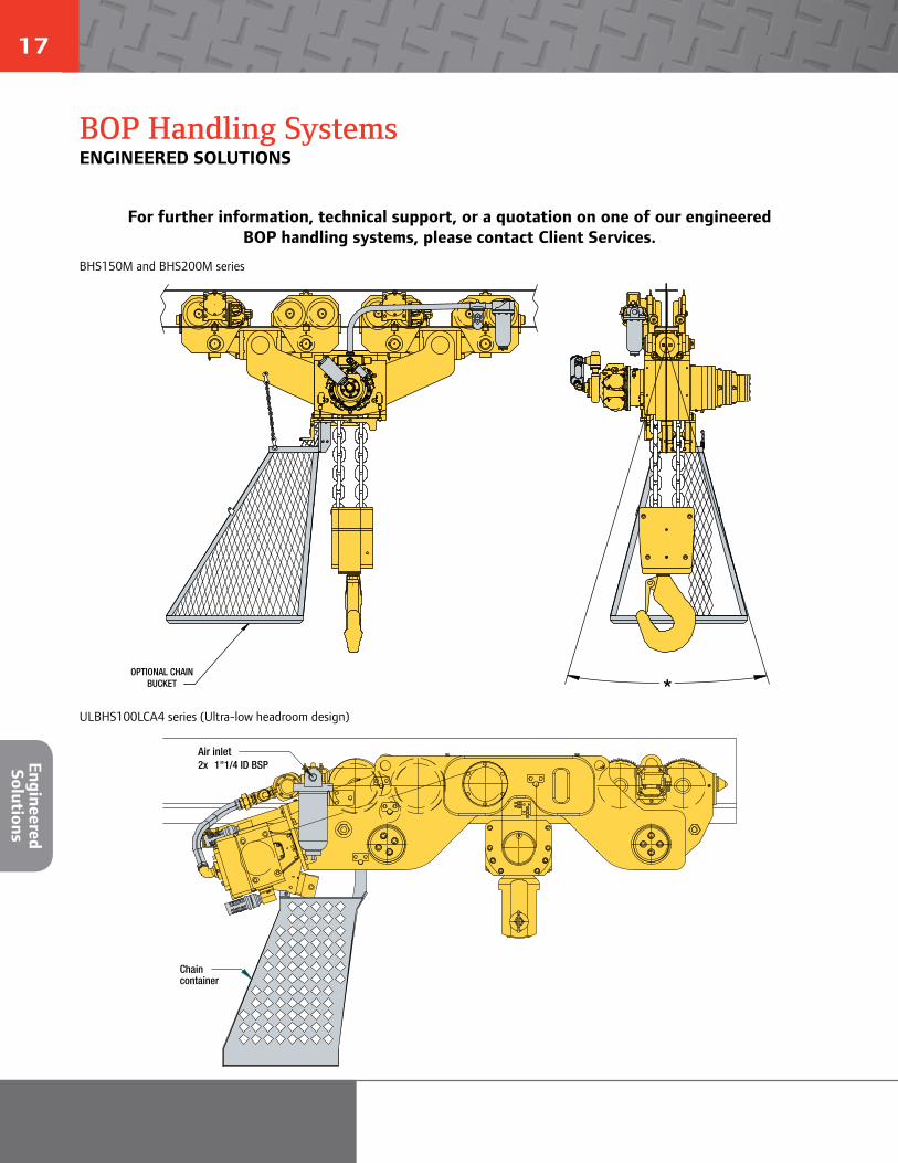
OPTIONAL CHAIN BUCKET *
Air inlet2x 1"1/4 ID BSP
Chaincontainer
BOP Handling SystemsENGINEERED SOLUTIONS
For further information, technical support, or a quotation on one of our engineered BOP handling systems, please contact Client Services.
BHS150M and BHS200M series
ULBHS100LCA4 series (Ultra-low headroom design)
Engineered Solutions


© 2014 Ingersoll Rand MHD55148 Back Cover Revision / 02102014
Ingersoll Rand (NYSE:IR) advances the quality of life by creating and sustaining safe, comfortable and efficient environments. Our people and our family of brands—including Club Car®, Ingersoll Rand®, Thermo King® and Trane® —work together to enhance the quality and comfort of air in homes and buildings; transport and protect food and perishables; secure homes and commercial properties; and increase industrial productivity and efficiency. Ingersoll Rand products range from complete compressed air systems, tools and pumps to material handling systems. The diverse and innovative products, services and solutions enhance our customers’ energy efficiency, productivity and operations. We are a $14 billion global business committed to a world of sustainable progress and enduring results. For more information, visit ingersollrand.com.
Ingersoll Rand, IR and the IR logo are trademarks of Ingersoll Rand, its subsidiaries and/or affiliates. All other trademarks are the property of their respective owners.
WARNING: This equipment is not designed for transporting people or lifting loads above people. It is the user’s responsibility to determine the suitability of this product for any particular use and to check compliance with applicable regulations. Before installation, see maintenance and operations manual for additional warnings and precautions
Nothing contained on these pages is intended to extend any warranty or representation, expressed or implied, regarding the product described herein. Any such warranties or other terms and conditions of sale of products shall be in accordance with Ingersoll Rand’s standard terms and conditions of sale for such products, which are available upon request.
Product improvement is a continuing goal at Ingersoll Rand. Designs and specifications are subject to change without notice or obligation.
Distributed by Tri-State Equipment Company Inc.Email: [email protected]
Web: www.tsoverheadcrane.comPH: 314-869-7200 | FAX: 314-869-7226
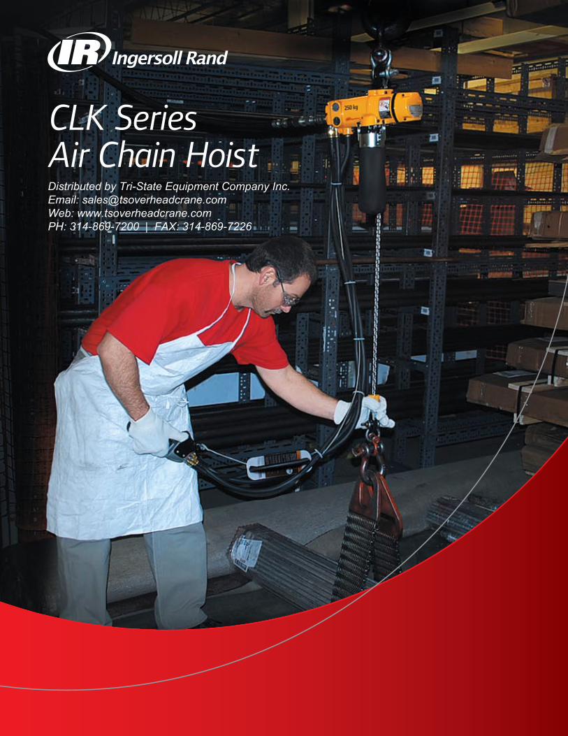
CLK Series Air Chain Hoist
Authorized Distributor:
Ingersoll Rand extends through offices and distributors in cities around the world. Contact the nearest Ingersoll Rand office or write to: Ingersoll Rand, P.O. Box 970 Annandale, NJ 08801 USA.
United States regional sales offices
Tech support, order entry and order status:Ingersoll Rand Customer Care510 Hester Drive, P.O. Box 618, White House, TN 37188Phone: 866-207-6923 or 800-IR-HoistFax: 615-285-0802
International
Ingersoll Rand Canada Inc.51 Worcester Road, Toronto, Ontario M9W 4K2Phone: 877-924-7435Fax: 416-213-4510Order Desk: 877-924-7435Fax: 416-213-4506
888-422-2258 (Toll free)
Europe, Middle East and AfricaIngersoll Rand Winch and Hoist Solutions
Douai Operations529, Avenue Roger Salengro,59450 SIN LE NOBLE, FrancePhone: 33-3-27-93-08-08Fax: 33-3-27-93-08-19E-mail: [email protected]
MéxicoIngersoll Rand S.A. de C.V.Boulevard Centro Industrial No. 11Industrial Puente de Vigas54070 Tlalnepantla, Estado de MéxicoPhone: 52 (55) 85 03 66 00 ext. 6685 & 6686Fax: 52 (55) 55 65 30 72
BrazilAlameda Caiapós 311Tamboré - Barueri - Sáo Paulo - Brazil 06460-110Phone: 55-11-2109 . 8950Fax: 55-11-2109 . 8998
Australia Ingersoll Rand Ltd.Landmark Corporate Centre45-47 Ventura PlaceDandenong South, Victoria 3175, AustraliaPhone: 61-3-8787-4300Fax: 61-3-8787-5510
Ingersoll Rand IndiaIngersoll Rand Wadco Tools Pvt Ltd.19, Chetak Apartments, Sheth Motisha Lane (Love Lane)Mazagon, Mumbai 400010 IndiaPhone: 91-22-2370-4972/3/4/5Fax: 91-22-2373-2326
Ingersoll Rand SEA Pte. Ltd.42 Benoi Road, Jurong, Singapore 629903Phone: 65-6861-1555Fax: 65-6862-1373
China Ingersoll Rand Co.10/F, Tower B, City Center of Shanghai,No.100 Zun Yi Road,Shanghai, 200051, P.R.C.Phone: 86-21-5452 9898Fax: 86-21-5410 1110
WARNING: This equipment is not designed for transporting people or lifting loads above people. It is the user’s responsibility to determine the suitability of this product for any particular use and to check compliance with applicable regulations. Before installation, see maintenance and operations manual for additional warnings and precautions.
Call 866-207-6923 for the distributor locations.Visit our website, ingersollrandproducts.com.
© 2010 Ingersoll-Rand Company
© 2010 Ingersoll-Rand Company IRITS-0110-003
Ingersoll Rand Industrial Technologies provides products, services and solutions
that enhance our customers’ energy efficiency, productivity and operations. Our
diverse and innovative products range from complete compressed air systems, tools
and pumps to material and fluid handling systems and environmentally friendly
microturbines. We also enhance productivity through solutions created by Club Car®,
the global leader in golf and utility vehicles for businesses and individuals.
ingersollrandproducts.com
Ingersoll Rand, the most trusted name for quality, high-value hoists, introduces the CLK Series, including 125-, 250- and 500-kilogram models.
Industry-leading durability, precision, and flexibility
The CLK Series is the smart choice for:
uDurability that delivers more uptime — With a FEM/ISO mechanism classification of 1Am/M4 (ASME HST-5 rating of A5), CLK Series hoists are duty-rated to go an incredible 800 full-load hours between overhauls.
u Flexibility that lets you get more jobs done — Patent-pending top hook operates with full 360-degree swivel motion or converts quickly to lock in 90-degree increments with no additional parts to buy.
u Lifting speed and precision control for enhanced ease of use — Lifting speed of 43 fpm (13.1m/min) for the 125 kg models and 32 fpm (9.8m/min) for the 250 kg models is the best in its class. Enhanced load “positioning” capabilities and an outstanding combination of motor control and brake release make this hoist ideal for precision applications.
u “Best-in-the-industry” quiet operation enhances safety and decreases operator fatigue —Sound levels of just 75 dBA make CLK Series hoists easy on operators, while also minimizing the overall ambient noise of the work site.
u Highly efficient air motor saves money — For hoists in its class, CLK Series gets the most performance from your compressed air output. The CLK Series consumes only 32 cfm (0.9 m3/min) of air lifting rated load and less then 16 cfm (0.5 m3/min) while lowering load.
For more information on how the CLK Series hoists can generate high return on your equipment investment:
See your local distributor
Call 866-207-6923
Visit ingersollrandproducts.com
Example: CL250K-2C10-C6U
C L 250K – 2 C 10 – C 6 U – E
Suspension
A = Fixed lug (adapts to RT010A trolley)
C = Swivel top hook
DA = Plain rigid trolley
Capacity
125K = 125 kg = 275 lb
250K = 250 kg = 550 lb
500K = 500 kg = 1,100 lb
Lower hook
C = Steel snap hook
HOW TO ORDER
Specify hoist by complete model number code as illustrated below. Specify accessories separately by part number. Note that 0 is a number, not a letter, in model part numbers.
Options
U = Fabric chain container
CE Package
E = Compliance with the European Machinery Directive – will include E-stop pendent control
Pendent Control Hose (ft)
6 = 6 ft
40 ft max. pendent hose length
Lift (ft)
10 = 10 ft
200 ft max. - CL125K & CL250K
100 ft. max. - CL500K
Control
0 = No Pendent
2 = Pendent
Link chaintype
Series
C = Series
Distributed by Tri-State Equipment Company Inc.Email: [email protected]: www.tsoverheadcrane.comPH: 314-869-7200 | FAX: 314-869-7226

CLK Series Air Chain Hoist
Authorized Distributor:
Ingersoll Rand extends through offices and distributors in cities around the world. Contact the nearest Ingersoll Rand office or write to: Ingersoll Rand, P.O. Box 970 Annandale, NJ 08801 USA.
United States regional sales offices
Tech support, order entry and order status:Ingersoll Rand Customer Care510 Hester Drive, P.O. Box 618, White House, TN 37188Phone: 866-207-6923 or 800-IR-HoistFax: 615-285-0802
International
Ingersoll Rand Canada Inc.51 Worcester Road, Toronto, Ontario M9W 4K2Phone: 877-924-7435Fax: 416-213-4510Order Desk: 877-924-7435Fax: 416-213-4506
888-422-2258 (Toll free)
Europe, Middle East and AfricaIngersoll Rand Winch and Hoist Solutions
Douai Operations529, Avenue Roger Salengro,59450 SIN LE NOBLE, FrancePhone: 33-3-27-93-08-08Fax: 33-3-27-93-08-19E-mail: [email protected]
MéxicoIngersoll Rand S.A. de C.V.Boulevard Centro Industrial No. 11Industrial Puente de Vigas54070 Tlalnepantla, Estado de MéxicoPhone: 52 (55) 85 03 66 00 ext. 6685 & 6686Fax: 52 (55) 55 65 30 72
BrazilAlameda Caiapós 311Tamboré - Barueri - Sáo Paulo - Brazil 06460-110Phone: 55-11-2109 . 8950Fax: 55-11-2109 . 8998
Australia Ingersoll Rand Ltd.Landmark Corporate Centre45-47 Ventura PlaceDandenong South, Victoria 3175, AustraliaPhone: 61-3-8787-4300Fax: 61-3-8787-5510
Ingersoll Rand IndiaIngersoll Rand Wadco Tools Pvt Ltd.19, Chetak Apartments, Sheth Motisha Lane (Love Lane)Mazagon, Mumbai 400010 IndiaPhone: 91-22-2370-4972/3/4/5Fax: 91-22-2373-2326
Ingersoll Rand SEA Pte. Ltd.42 Benoi Road, Jurong, Singapore 629903Phone: 65-6861-1555Fax: 65-6862-1373
China Ingersoll Rand Co.10/F, Tower B, City Center of Shanghai,No.100 Zun Yi Road,Shanghai, 200051, P.R.C.Phone: 86-21-5452 9898Fax: 86-21-5410 1110
WARNING: This equipment is not designed for transporting people or lifting loads above people. It is the user’s responsibility to determine the suitability of this product for any particular use and to check compliance with applicable regulations. Before installation, see maintenance and operations manual for additional warnings and precautions.
Call 866-207-6923 for the distributor locations.Visit our website, ingersollrandproducts.com.
© 2010 Ingersoll-Rand Company
© 2010 Ingersoll-Rand Company IRITS-0110-003
Ingersoll Rand Industrial Technologies provides products, services and solutions
that enhance our customers’ energy efficiency, productivity and operations. Our
diverse and innovative products range from complete compressed air systems, tools
and pumps to material and fluid handling systems and environmentally friendly
microturbines. We also enhance productivity through solutions created by Club Car®,
the global leader in golf and utility vehicles for businesses and individuals.
ingersollrandproducts.com
Ingersoll Rand, the most trusted name for quality, high-value hoists, introduces the CLK Series, including 125-, 250- and 500-kilogram models.
Industry-leading durability, precision, and flexibility
The CLK Series is the smart choice for:
uDurability that delivers more uptime — With a FEM/ISO mechanism classification of 1Am/M4 (ASME HST-5 rating of A5), CLK Series hoists are duty-rated to go an incredible 800 full-load hours between overhauls.
u Flexibility that lets you get more jobs done — Patent-pending top hook operates with full 360-degree swivel motion or converts quickly to lock in 90-degree increments with no additional parts to buy.
u Lifting speed and precision control for enhanced ease of use — Lifting speed of 43 fpm (13.1m/min) for the 125 kg models and 32 fpm (9.8m/min) for the 250 kg models is the best in its class. Enhanced load “positioning” capabilities and an outstanding combination of motor control and brake release make this hoist ideal for precision applications.
u “Best-in-the-industry” quiet operation enhances safety and decreases operator fatigue — Sound levels of just 75 dBA make CLK Series hoists easy on operators, while also minimizing the overall ambient noise of the work site.
u Highly efficient air motor saves money — For hoists in its class, CLK Series gets the most performance from your compressed air output. The CLK Series consumes only 32 cfm (0.9 m3/min) of air lifting rated load and less then 16 cfm (0.5 m3/min) while lowering load.
For more information on how the CLK Series hoists can generate high return on your equipment investment:
See your local distributor
Call 866-207-6923
Visit ingersollrandproducts.com
Example: CL250K-2C10-C6U
C L 250K – 2 C 10 – C 6 U – E
Suspension
A = Fixed lug (adapts to RT010A trolley)
C = Swivel top hook
DA = Plain rigid trolley
Capacity
125K = 125 kg = 275 lb
250K = 250 kg = 550 lb
500K = 500 kg = 1,100 lb
Lower hook
C = Steel snap hook
HOW TO ORDER
Specify hoist by complete model number code as illustrated below. Specify accessories separately by part number. Note that 0 is a number, not a letter, in model part numbers.
Options
U = Fabric chain container
CE Package
E = Compliance with the European Machinery Directive – will include E-stop pendent control
Pendent Control Hose (ft)
6 = 6 ft
40 ft max. pendent hose length
Lift (ft)
10 = 10 ft
200 ft max. - CL125K & CL250K
100 ft. max. - CL500K
Control
0 = No Pendent
2 = Pendent
Link chaintype
Series
C = Series
CLK SeriesPneumatic hoists: 125-, 250-, and 500-kg models
ingersollrandproducts.com/lifting866-207-6923
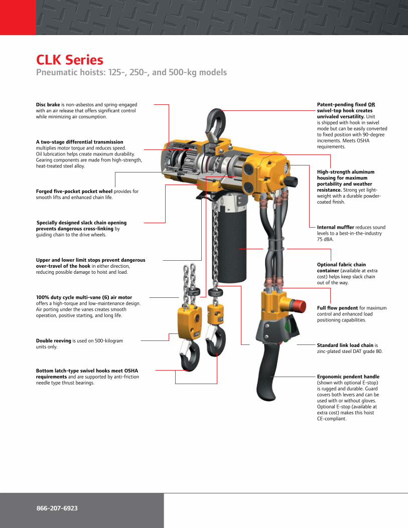
Disc brake is non-asbestos and spring-engaged with an air release that offers significant control while minimizing air consumption.
A two-stage differential transmission multiplies motor torque and reduces speed. Oil lubrication helps create maximum durability. Gearing components are made from high-strength, heat-treated steel alloy.
Forged five-pocket pocket wheel provides for smooth lifts and enhanced chain life.
Specially designed slack chain opening prevents dangerous cross-linking by guiding chain to the drive wheels.
Upper and lower limit stops prevent dangerous over-travel of the hook in either direction, reducing possible damage to hoist and load.
100% duty cycle multi-vane (6) air motor offers a high-torque and low-maintenance design. Air porting under the vanes creates smooth operation, positive starting, and long life.
Double reeving is used on 500-kilogram units only.
Bottom latch-type swivel hooks meet OSHA requirements and are supported by anti-friction needle type thrust bearings.
Patent-pending fixed OR swivel-top hook creates unrivaled versatility. Unit is shipped with hook in swivel mode but can be easily converted to fixed position with 90-degree increments. Meets OSHA requirements.
High-strength aluminum housing for maximum portability and weather resistance. Strong yet light-weight with a durable powder-coated finish.
Internal muffler reduces sound levels to a best-in-the-industry 75 dBA.
Optional fabric chain container (available at extra cost) helps keep slack chain out of the way.
Full flow pendent for maximum control and enhanced load positioning capabilities.
Standard link load chain is zinc-plated steel DAT grade 80.
Ergonomic pendent handle (shown with optional E-stop) is rugged and durable. Guard covers both levers and can be used with or without gloves. Optional E-stop (available at extra cost) makes this hoist CE-compliant.
CLK SeriesPneumatic hoists: 125-, 250-, and 500-kg models
AccessoriesPneumatic hoists: 125-, 250-, and 500-kg models
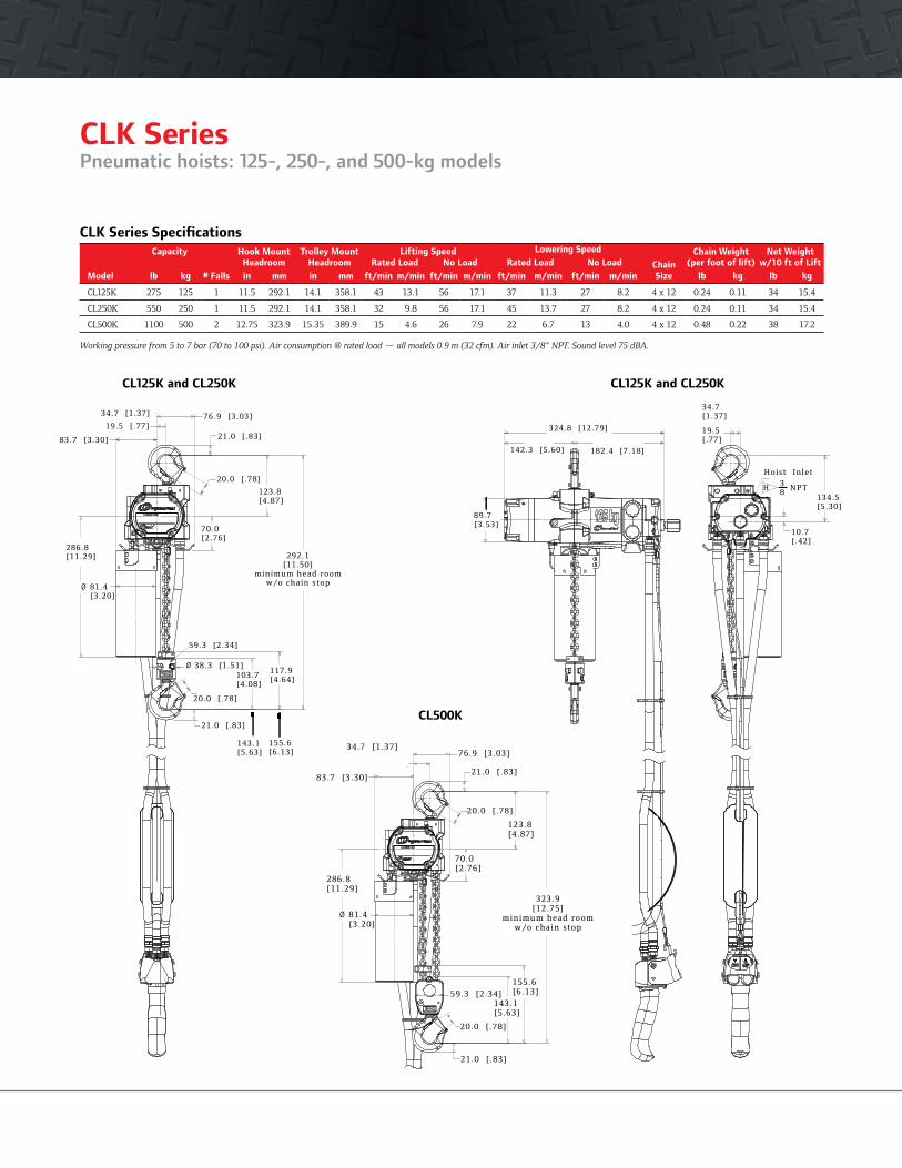
CLK Series Specifications
Model
Capacity
# Falls
Hook MountHeadroom
Trolley MountHeadroom
Lifting Speed Lowering Speed
ChainSize
Chain Weight (per foot of lift)
Net Weightw/10 ft of Lift
kgRated Load No Load Rated Load No Load
lb in mm in mm ft/min m/min ft/min m/min ft/min m/min ft/min m/min lb kg lb kg
CL125K 275 125 1 11.5 292.1 14.1 358.1 43 13.1 56 17.1 37 11.3 27 8.2 4 x 12 0.24 0.11 34 15.4
CL250K 550 250 1 11.5 292.1 14.1 358.1 32 9.8 56 17.1 45 13.7 27 8.2 4 x 12 0.24 0.11 34 15.4
CL500K 1100 500 2 12.75 323.9 15.35 389.9 15 4.6 26 7.9 22 6.7 13 4.0 4 x 12 0.48 0.22 38 17.2
Working pressure from 5 to 7 bar (70 to 100 psi). Air consumption @ rated load — all models 0.9 m (32 cfm). Air inlet 3/8” NPT. Sound level 75 dBA.
CL125K and CL250K
PT Series Hook-on Trolley
Model Capacity
Flange Adjustment
Min. Beam Height
Min. Curve Radius Weight Kit no.
Flange Adjustment Weight
lb metric tons in in in lb (order separate) in lb
STANDARD SERIES
PT005-8 1,100 0.50 2.6 – 8 4 36 19.7 PT005-WFK 8 – 13 5.5
Wheels are cast iron and the universal tread fits either flat or tapered beams.
PT005-8
RT010 Series TrolleyFits Beam Minimum
Trolley Capacity Flange Width Turning RadiusPart Number metric tons in in
RT010 0.25 - 1 2.7 - 6 36
Wheels have universal tread for use on flat or tapered beams.
Filters - Regulators - LubricatorsSize (in) Flow Rate Adj. Pressure Range Bowl Capacity Height x Width
Part No. NPTF scfm psig oz in
TRIO UNITS: FILTERS, REGULATORS, LUBRICATORS
C38341-810 1/2 150 5 – 250 4 6 x 8.7
C38451-810 3/4 200 5 – 250 4 8.6 x 11.1
C38461-810 1 215 5 – 250 4 8.6 x 11.1C38341-810
Quick Exhaust ValvesPart For Use Control Pendent Length Number With Type Style ft
MR-939 All CLK Series Full-flow 3/8” NPT 15 – 40
The first pair of full-flow valves will be installed between 7 and 8 ft from the pendent handle after pendent hose length reaches 16 ft. Any additional valves will equally divide the remaining hose length.
Link Chain Canvas BasketCapacity
Part No. ft
CL250K-749-20 20
CL250K-749-40 40
E-Stop Pendent HandlePart Number Description
45667359 Pendent handle assembly with E-stop function
Cousin to the PT Series trolley, the twin suspension shaft RT Series trolley offers a rigid connection for the CLK Series of air chain hoists. A lug adapter is required for use.
76.9 [3 .03]
21.0 [ .83]19.5 [ .77]
83.7 [3 .30]
20.0 [ .78]
70.0[2 .76]
292.1[11.50]
minimum head roomw/o chain stop
123.8[4 .87]
286.8[11.29]
81.4[3 .20]
117.9[4 .64]103.7
[4 .08]
38.3 [1 .51]
20.0 [ .78]
21.0 [ .83]
34.7 [1 .37]
59.3 [2 .34]
155.6[6 .13]
143.1[5 .63]
19.5[ .77]
Hoist In let
134.5[5 .30]
NPT
10.7[ .42]
H38
182.4 [7 .18]
324.8 [12.79]
142.3 [5 .60]
89.7[3 .53]
34.7[1 .37]
E-Stop Pendent Handle
Link ChainCanvas Basket
76.9 [3 .03]
21.0 [ .83]
20.0 [ .78]
123.8[4 .87]
70.0[2 .76]
323.9[12.75]
minimum head roomw/o chain stop
34.7 [1 .37]
83.7 [3 .30]
286.8[11.29]
81.4[3 .20]
20.0 [ .78]
21.0 [ .83]
59.3 [2 .34]155.6[6 .13]
143.1[5 .63]
CL500K
CL125K and CL250K
CLK SeriesPneumatic hoists: 125-, 250-, and 500-kg models
ingersollrandproducts.com/lifting866-207-6923
Disc brake is non-asbestos and spring-engaged with an air release that offers significant control while minimizing air consumption.
A two-stage differential transmissionmultiplies motor torque and reduces speed. Oil lubrication helps create maximum durability. Gearing components are made from high-strength, heat-treated steel alloy.
Forged five-pocket pocket wheel provides for smooth lifts and enhanced chain life.
Specially designed slack chain opening prevents dangerous cross-linking by guiding chain to the drive wheels.
Upper and lower limit stops prevent dangerous over-travel of the hook in either direction, reducing possible damage to hoist and load.
100% duty cycle multi-vane (6) air motor offers a high-torque and low-maintenance design. Air porting under the vanes creates smooth operation, positive starting, and long life.
Double reeving is used on 500-kilogram units only.
Bottom latch-type swivel hooks meet OSHA requirements and are supported by anti-friction needle type thrust bearings.
Patent-pending fixed ORswivel-top hook creates unrivaled versatility. Unit is shipped with hook in swivel mode but can be easily converted to fixed position with 90-degree increments. Meets OSHArequirements.
High-strength aluminum housing for maximum portability and weather resistance. Strong yet light-weight with a durable powder-coated finish.
Internal muffler reduces sound levels to a best-in-the-industry 75 dBA.
Optional fabric chain container (available at extra cost) helps keep slack chain out of the way.
Full flow pendent for maximum control and enhanced load positioning capabilities.
Standard link load chain is zinc-plated steel DAT grade 80.
Ergonomic pendent handle(shown with optional E-stop) is rugged and durable. Guard covers both levers and can be used with or without gloves. Optional E-stop (available at extra cost) makes this hoist CE-compliant.
CLK SeriesPneumatic hoists: 125-, 250-, and 500-kg models
AccessoriesPneumatic hoists: 125-, 250-, and 500-kg models
CLK Series Specifications
Model
Capacity
# Falls
Hook MountHeadroom
Trolley MountHeadroom
Lifting Speed Lowering Speed
ChainSize
Chain Weight (per foot of lift)
Net Weightw/10 ft of Lift
kgRated Load No Load Rated Load No Load
lb in mm in mm ft/min m/min ft/min m/min ft/min m/min ft/min m/min lb kg lb kg
CL125K 275 125 1 11.5 292.1 14.1 358.1 43 13.1 56 17.1 37 11.3 27 8.2 4 x 12 0.24 0.11 34 15.4
CL250K 550 250 1 11.5 292.1 14.1 358.1 32 9.8 56 17.1 45 13.7 27 8.2 4 x 12 0.24 0.11 34 15.4
CL500K 1100 500 2 12.75 323.9 15.35 389.9 15 4.6 26 7.9 22 6.7 13 4.0 4 x 12 0.48 0.22 38 17.2
Working pressure from 5 to 7 bar (70 to 100 psi). Air consumption @ rated load — all models 0.9 m (32 cfm). Air inlet 3/8” NPT. Sound level 75 dBA.
CL125K and CL250K
PT Series Hook-on Trolley
Model Capacity
Flange Adjustment
Min. Beam Height
Min. Curve Radius Weight Kit no.
Flange Adjustment Weight
lb metric tons in in in lb (order separate) in lb
STANDARD SERIES
PT005-8 1,100 0.50 2.6 – 8 4 36 19.7 PT005-WFK 8 – 13 5.5
Wheels are cast iron and the universal tread fits either flat or tapered beams.
PT005-8
RT010 Series TrolleyFits Beam Minimum
Trolley Capacity Flange Width Turning RadiusPart Number metric tons in in
RT010 0.25 - 1 2.7 - 6 36
Wheels have universal tread for use on flat or tapered beams.
Filters - Regulators - LubricatorsSize (in) Flow Rate Adj. Pressure Range Bowl Capacity Height x Width
Part No. NPTF scfm psig oz in
TRIO UNITS: FILTERS, REGULATORS, LUBRICATORS
C38341-810 1/2 150 5 – 250 4 6 x 8.7
C38451-810 3/4 200 5 – 250 4 8.6 x 11.1
C38461-810 1 215 5 – 250 4 8.6 x 11.1C38341-810
Quick Exhaust ValvesPart For Use Control Pendent Length Number With Type Style ft
MR-939 All CLK Series Full-flow 3/8” NPT 15 – 40
The first pair of full-flow valves will be installed between 7 and 8 ft from the pendent handle after pendent hose length reaches 16 ft. Any additional valves will equally divide the remaining hose length.
Link Chain Canvas BasketCapacity
Part No. ft
CL250K-749-20 20
CL250K-749-40 40
E-Stop Pendent HandlePart Number Description
45667359 Pendent handle assembly with E-stop function
Cousin to the PT Series trolley, the twin suspension shaft RT Series trolley offers a rigid connection for the CLK Series of air chain hoists. A lug adapter is required for use.
76.9 [3 .03]
21.0 [ .83]19.5 [ .77]
83.7 [3 .30]
20.0 [ .78]
70.0[2 .76]
292.1[11.50]
minimum head roomw/o chain stop
123.8[4 .87]
286.8[11.29]
81.4[3 .20]
117.9[4 .64]103.7
[4 .08]
38.3 [1 .51]
20.0 [ .78]
21.0 [ .83]
34.7 [1 .37]
59.3 [2 .34]
155.6[6 .13]
143.1[5 .63]
19.5[ .77]
Hoist In let
134.5[5 .30]
NPT
10.7[ .42]
H38
182.4 [7 .18]
324.8 [12.79]
142.3 [5 .60]
89.7[3 .53]
34.7[1 .37]
E-Stop Pendent Handle
Link ChainCanvas Basket
76.9 [3 .03]
21.0 [ .83]
20.0 [ .78]
123.8[4 .87]
70.0[2 .76]
323.9[12.75]
minimum head roomw/o chain stop
34.7 [1 .37]
83.7 [3 .30]
286.8[11.29]
81.4[3 .20]
20.0 [ .78]
21.0 [ .83]
59.3 [2 .34]155.6[6 .13]
143.1[5 .63]
CL500K
CL125K and CL250K

CLK SeriesPneumatic hoists: 125-, 250-, and 500-kg models
866-207-6923
Disc brake is non-asbestos and spring-engaged with an air release that offers significant control while minimizing air consumption.
A two-stage differential transmissionmultiplies motor torque and reduces speed. Oil lubrication helps create maximum durability. Gearing components are made from high-strength, heat-treated steel alloy.
Forged five-pocket pocket wheel provides for smooth lifts and enhanced chain life.
Specially designed slack chain opening prevents dangerous cross-linking by guiding chain to the drive wheels.
Upper and lower limit stops prevent dangerous over-travel of the hook in either direction, reducing possible damage to hoist and load.
100% duty cycle multi-vane (6) air motor offers a high-torque and low-maintenance design. Air porting under the vanes creates smooth operation, positive starting, and long life.
Double reeving is used on 500-kilogram units only.
Bottom latch-type swivel hooks meet OSHA requirements and are supported by anti-friction needle type thrust bearings.
Patent-pending fixed ORswivel-top hook creates unrivaled versatility. Unit is shipped with hook in swivel mode but can be easily converted to fixed position with 90-degree increments. Meets OSHArequirements.
High-strength aluminum housing for maximum portability and weather resistance. Strong yet light-weight with a durable powder-coated finish.
Internal muffler reduces sound levels to a best-in-the-industry 75 dBA.
Optional fabric chain container (available at extra cost) helps keep slack chain out of the way.
Full flow pendent for maximum control and enhanced load positioning capabilities.
Standard link load chain is zinc-plated steel DAT grade 80.
Ergonomic pendent handle(shown with optional E-stop) is rugged and durable. Guard covers both levers and can be used with or without gloves. Optional E-stop (available at extra cost) makes this hoist CE-compliant.
CLK SeriesPneumatic hoists: 125-, 250-, and 500-kg models
AccessoriesPneumatic hoists: 125-, 250-, and 500-kg models
CLK Series Specifications
Model
Capacity
# Falls
Hook MountHeadroom
Trolley MountHeadroom
Lifting Speed Lowering Speed
ChainSize
Chain Weight (per foot of lift)
Net Weightw/10 ft of Lift
kgRated Load No Load Rated Load No Load
lb in mm in mm ft/min m/min ft/min m/min ft/min m/min ft/min m/min lb kg lb kg
CL125K 275 125 1 11.5 292.1 14.1 358.1 43 13.1 56 17.1 37 11.3 27 8.2 4 x 12 0.24 0.11 34 15.4
CL250K 550 250 1 11.5 292.1 14.1 358.1 32 9.8 56 17.1 45 13.7 27 8.2 4 x 12 0.24 0.11 34 15.4
CL500K 1100 500 2 12.75 323.9 15.35 389.9 15 4.6 26 7.9 22 6.7 13 4.0 4 x 12 0.48 0.22 38 17.2
Working pressure from 5 to 7 bar (70 to 100 psi). Air consumption @ rated load — all models 0.9 m (32 cfm). Air inlet 3/8” NPT. Sound level 75 dBA.
CL125K and CL250K
PT Series Hook-on Trolley
Model Capacity
Flange Adjustment
Min. Beam Height
Min. Curve Radius Weight Kit no.
Flange Adjustment Weight
lb metric tons in in in lb (order separate) in lb
STANDARD SERIES
PT005-8 1,100 0.50 2.6 – 8 4 36 19.7 PT005-WFK 8 – 13 5.5
Wheels are cast iron and the universal tread fits either flat or tapered beams.
PT005-8
RT010 Series TrolleyFits Beam Minimum
Trolley Capacity Flange Width Turning Radius Part Number metric tons in in
RT010 0.25 - 1 2.7 - 6 36
Wheels have universal tread for use on flat or tapered beams.
Filters - Regulators - LubricatorsSize (in) Flow Rate Adj. Pressure Range Bowl Capacity Height x Width
Part No. NPTF scfm psig oz in
TRIO UNITS: FILTERS, REGULATORS, LUBRICATORS
C38341-810 1/2 150 5 – 250 4 6 x 8.7
C38451-810 3/4 200 5 – 250 4 8.6 x 11.1
C38461-810 1 215 5 – 250 4 8.6 x 11.1C38341-810
Quick Exhaust Valves Part For Use Control Pendent Length Number With Type Style ft
MR-939 All CLK Series Full-flow 3/8” NPT 15 – 40
The first pair of full-flow valves will be installed between 7 and 8 ft from the pendent handle after pendent hose length reaches 16 ft. Any additional valves will equally divide the remaining hose length.
Link Chain Canvas BasketCapacity
Part No. ft
CL250K-749-20 20
CL250K-749-40 40
E-Stop Pendent HandlePart Number Description
45667359 Pendent handle assembly with E-stop function
Cousin to the PT Series trolley, the twin suspension shaft RT Series trolley offers a rigid connection for the CLK Series of air chain hoists. A lug adapter is required for use.
76.9 [3 .03]
21.0 [ .83]19.5 [ .77]
83.7 [3 .30]
20.0 [ .78]
70.0[2 .76]
292.1[11.50]
minimum head roomw/o chain stop
123.8[4 .87]
286.8[11.29]
81.4[3 .20]
117.9[4 .64]103.7
[4 .08]
38.3 [1 .51]
20.0 [ .78]
21.0 [ .83]
34.7 [1 .37]
59.3 [2 .34]
155.6[6 .13]
143.1[5 .63]
19.5[ .77]
Hoist In let
134.5[5 .30]
NPT
10.7[ .42]
H38
182.4 [7 .18]
324.8 [12.79]
142.3 [5 .60]
89.7[3 .53]
34.7[1 .37]
E-Stop Pendent Handle
Link ChainCanvas Basket
76.9 [3 .03]
21.0 [ .83]
20.0 [ .78]
123.8[4 .87]
70.0[2 .76]
323.9[12.75]
minimum head roomw/o chain stop
34.7 [1 .37]
83.7 [3 .30]
286.8[11.29]
81.4[3 .20]
20.0 [ .78]
21.0 [ .83]
59.3 [2 .34]155.6[6 .13]
143.1[5 .63]
CL500K
CL125K and CL250K
CLK Series Air Chain Hoist
Ingersoll Rand extends through offices and distributors in cities around the world. Contact the nearest Ingersoll Rand office or write to: Ingersoll Rand, P.O. Box 970 Annandale, NJ 08801 USA.
United States regional sales offices
WARNING: This equipment is not designed for transporting people or lifting loads above people. It is the user’s responsibility to determine the suitability of this product for any particular use and to check compliance with applicable regulations. Before installation, see maintenance and operations manual for additional warnings and precautions.
Call 314-869-7200 for the distributor locations. Visit our website, www.tsoverheadcrane.com.
© 2010 Ingersoll-Rand Company
© 2010 Ingersoll-Rand Company IRITS-0110-003
Ingersoll Rand Industrial Technologies provides products, services and solutions
that enhance our customers’ energy efficiency, productivity and operations. Our
diverse and innovative products range from complete compressed air systems, tools
and pumps to material and fluid handling systems and environmentally friendly
microturbines. We also enhance productivity through solutions created by Club Car®,
the global leader in golf and utility vehicles for businesses and individuals.
Ingersoll Rand, the most trusted name for quality, high-value hoists, introduces the CLK Series, including 125-, 250- and 500-kilogram models.
Industry-leading durability, precision, and flexibility
The CLK Series is the smart choice for:
uDurability that delivers more uptime — With a FEM/ISO mechanism classification of 1Am/M4 (ASME HST-5 rating of A5), CLK Series hoists are duty-rated to go an incredible 800 full-load hours between overhauls.
u Flexibility that lets you get more jobs done — Patent-pending top hook operates with full 360-degree swivel motion or converts quickly to lock in 90-degree increments with no additional parts to buy.
u Lifting speed and precision control for enhanced ease of use — Lifting speed of 43 fpm (13.1m/min) for the 125 kg models and 32 fpm (9.8m/min) for the 250 kg models is the best in its class. Enhanced load “positioning” capabilities and an outstanding combination of motor control and brake release make this hoist ideal for precision applications.
u “Best-in-the-industry” quiet operation enhances safety and decreases operator fatigue —Sound levels of just 75 dBA make CLK Series hoists easy on operators, while also minimizing the overall ambient noise of the work site.
u Highly efficient air motor saves money — For hoists in its class, CLK Series gets the most performance from your compressed air output. The CLK Series consumes only 32 cfm (0.9 m3/min) of air lifting rated load and less then 16 cfm (0.5 m3/min) while lowering load.
For more information on how the CLK Series hoists can generate high return on your equipment investment:
See your local distributor
Call 866-207-6923
Visit ingersollrandproducts.com
Example: CL250K-2C10-C6U
C L 250K – 2 C 10 – C 6 U – E
Suspension
A = Fixed lug (adapts to RT010A trolley)
C = Swivel top hook
DA = Plain rigid trolley
Capacity
125K = 125 kg = 275 lb
250K = 250 kg = 550 lb
500K = 500 kg = 1,100 lb
Lower hook
C = Steel snap hook
HOW TO ORDER
Specify hoist by complete model number code as illustrated below. Specify accessories separately by part number. Note that 0 is a number, not a letter, in model part numbers.
Options
U = Fabric chain container
CE Package
E = Compliance with the European Machinery Directive – will include E-stop pendent control
Pendent Control Hose (ft)
6 = 6 ft
40 ft max. pendent hose length
Lift (ft)
10 = 10 ft
200 ft max. - CL125K & CL250K
100 ft. max. - CL500K
Control
0 = No Pendent
2 = Pendent
Link chaintype
Series
C = Series
Distributed by Tri-State Equipment Company Inc.Email: [email protected]: www.tsoverheadcrane.comPH: 314-869-7200 | FAX: 314-869-7226
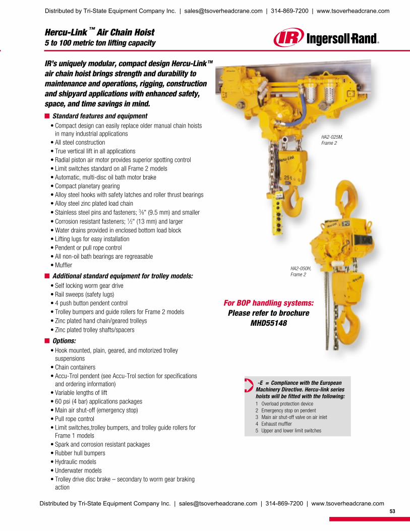
Hercu-Link ™ Air Chain Hoist5 to 100 metric ton lifting capacity
IR’s uniquely modular, compact design Hercu-Link TM
air chain hoist brings strength and durability tomaintenance and operations, rigging, constructionand shipyard applications with enhanced safety,space, and time savings in mind.n Standard features and equipment
• Compact design can easily replace older manual chain hoistsin many industrial applications
• All steel construction• True vertical lift in all applications• Radial piston air motor provides superior spotting control• Limit switches standard on all Frame 2 models• Automatic, multi-disc oil bath motor brake• Compact planetary gearing• Alloy steel hooks with safety latches and roller thrust bearings• Alloy steel zinc plated load chain• Stainless steel pins and fasteners; 3⁄8" (9.5 mm) and smaller• Corrosion resistant fasteners; 1⁄2" (13 mm) and larger• Water drains provided in enclosed bottom load block• Lifting lugs for easy installation• Pendent or pull rope control• All non-oil bath bearings are regreasable• Muffler
n Additional standard equipment for trolley models:• Self locking worm gear drive• Rail sweeps (safety lugs)• 4 push button pendent control• Trolley bumpers and guide rollers for Frame 2 models• Zinc plated hand chain/geared trolleys• Zinc plated trolley shafts/spacers
n Options:• Hook mounted, plain, geared, and motorized trolley
suspensions• Chain containers• Accu-Trol pendent (see Accu-Trol section for specifications
and ordering information)• Variable lengths of lift• 60 psi (4 bar) applications packages• Main air shut-off (emergency stop)• Pull rope control• Limit switches,trolley bumpers, and trolley guide rollers for
Frame 1 models• Spark and corrosion resistant packages• Rubber hull bumpers• Hydraulic models• Underwater models• Trolley drive disc brake – secondary to worm gear braking
action
HA2-050H,Frame 2
HA2-025M,Frame 2
ò -E = Compliance with the EuropeanMachinery Directive. Hercu-link serieshoists will be fitted with the following:1 Overload protection device2 Emergency stop on pendent3 Main air shut-off valve on air inlet4 Exhaust muffler5 Upper and lower limit switches
For BOP handling systems:Please refer to brochure
MHD55148
53
Distributed by Tri-State Equipment Company Inc. | [email protected] | 314-869-7200 | www.tsoverheadcrane.com
Distributed by Tri-State Equipment Company Inc. | [email protected] | 314-869-7200 | www.tsoverheadcrane.com

54
Hercu-Link ™ Air Chain Hoist5 to 100 metric ton lifting capacity
Specifications: performance is based on 105 psi (7 bar) air inlet pressure with motor runningModel no. Capacity Standard lift Hoist lift (1) (2) Hoist lower Hoist Avg. air cons. Chain Std headroom (3) Unit weight Ship weight
tons ft m ft/min m/min ft/min m/min hp cfm m3/min falls in. mm lbs kg lbs kg
Frame 1/hook mounted hoist (16 mm chain)
HA1-005H 5 10 3 10 3 15 4.6 3.8 165 4.7 1 27.63 702 520 236 670 304
HA1-010H 10 10 3 5 1.5 7.5 2.3 3.8 165 4.7 2 35.50 902 610 277 760 345
HA1-015H 15 10 3 3.25 1 5 1.5 3.8 165 4.7 3 41.88 1064 875 398 1125 511
HA1-020H 20 10 3 2.5 .76 3.75 1.1 3.8 165 4.7 4 42.50 1080 975 443 1275 580
Frame 2/hook mounted hoist (22 mm chain)
HA2-012H 12.5 10 3 8 2.4 12 3.7 9.4 280 8 1 38.50 978 965 439 1215 552
HA2-025H 25 10 3 4 1.2 6 1.8 9.4 280 8 2 51.13 1299 1235 561 1685 766
HA2-037H 37.5 10 3 2.5 .76 3.75 1.1 9.4 280 8 3 66.50 1689 2230 1014 2680 1218
HA2-050H 50 10 3 2 .61 3 0.9 9.4 280 8 4 75.06 1907 2955 1343 3330 1514
Frame 3/hook mounted hoist (32 mm chain)
HA3-075H 75 10 3 2.5 0.76 2.5 0.76 25 500 14.3 3 83 2108 7600 3453 8450 3839
HA3-100H 100 10 3 2 0.61 2 0.61 25 500 14.3 4 96 2432 8000 3635 8850 4021
Frame 1/trolley mounted hoist (16 mm chain)
HA1-005M (or V) 5 10 3 10 3 15 4.6 3.8 165 4.7 1 23.56 598 905 411 1055 480
HA1-010M (or V) 10 10 3 5 1.5 7.5 2.3 3.8 165 4.7 2 30.50 775 1105 502 1305 593
HA1-015M (or V) 15 10 3 3.25 1 5 1.5 3.8 165 4.7 3 35.25 895 1315 598 1565 711
HA1-020M (or V) 20 10 3 2.5 .76 3.75 1.1 3.8 165 4.7 4 34.96 878 1425 648 1725 784
Frame 2/trolley mounted hoist (22 mm chain)
HA2-012M (or V) 12.5 10 3 8 2.4 12 3.7 9.4 280 8 1 24.69 627 1415 643 1665 757
HA2-025M (or V) 25 10 3 4 1.2 6 1.8 9.4 280 8 2 40.94 1040 1660 755 2110 959
HA2-037M (or V) 37.5 10 3 2.5 .76 3.75 1.1 9.4 280 8 3 48.94 1243 3700 1682 4150 1886
HA2-050M (or V) 50 10 3 2 .61 3 0.9 9.4 280 8 4 53.00 1346 4665 2120 5440 2473
Frame 3/trolley mounted hoist (32 mm chain)
HA3-075M 75 10 3 2.5 0.76 2.5 0.76 25 500 14.3 3 (4) (4) (4) (4) (4) (4)
HA3-100M 100 10 3 2 0.61 2 0.61 25 500 14.3 4 (4) (4) (4) (4) (4) (4)
(1) Chain bucket dimensions vary per length of lift. Contact technical sales for specific requirements.(2) Lifting speed will be reduced when 4-bar gearing (option Q ) is ordered.(3) Headroom for plain and geared trolleys are the same as motorized trolley.(4) Contact factory for specific trolley configuration.(5) Air Inlet Sizes: Frame 1, 3/4”
Frame 2, 1”Frame 3, 1-1/2”
Hercu-Link Frame 2 operating data at 105 psi/7 bar (dynamic)Series at rated load at half load at no load
Up Down Up Down Up Downfpm m/min fpm m/min fpm m/min fpm m/min fpm m/min fpm m/min
HA2-012H 7 2.1 16 4.9 13 4.0 11.5 3.5 19 5.8 7 2.1
HA2-025H 3.5 1.1 8 2.4 6.5 2.0 5.7 1.7 9.5 2.9 3.5 1.1
HA2-037H 2.3 .07 5.3 1.6 4.3 1.3 3.8 1.2 6.3 1.9 2.3 0.7
HA2-050H 1.7 .05 4 1.2 3.2 1.0 2.9 0.9 4.75 1.4 1.75 0.5
Performance fgures are based on 1-1/4 inch (32 mm) I.D. air hose. Air consumption at no load is 280 cfm (7.84 m3/min); at half load is 215 cfm (6.02 m3/min) and at rated load is150 cfm (4.2 m3/min);
Distributed by Tri-State Equipment Company Inc. | [email protected] | 314-869-7200 | www.tsoverheadcrane.com
55
N
F
F
P
Y
*
*
B
C
M
G H
L
K
A
J
*
Hercu-Link ™ Air Chain Hoist5 to 100 metric ton lifting capacity
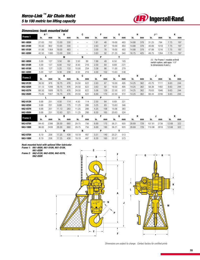
Hook mounted hoist with optional filter-lubricatorFrame 1: HA1-005H, HA1-010H, HA1-O15H,
HA1-020HFrame 2: HA2-012H, HA2-025H, HA2-037H,
HA2-050H
Dimensions: hook mounted hoist
Frame 1A (1) B C F G H J (1) K
in. mm in. mm in. mm in. mm in. mm in. mm in. mm in. mm
HA1-005H 27.63 702 13.00 330 – – 1.81 46 19.00 483 14.88 378 31.25 794 7.75 197
HA1-010H 35.50 902 13.00 330 – – 2.63 67 19.00 483 14.88 378 40.06 1018 7.75 197
HA1-015H 41.88 1064 19.00 483 – – 3.00 76 19.00 483 14.88 378 47.88 1216 7.75 197
HA1-020H 42.50 1080 13.00 330 – – 3.63 92 21.25 540 16.75 425 49.75 1264 7.75 197
L M N P Y
HA1-005H 5.00 127 3.50 89 3.50 89 7.88 48 6.50 165
HA1-010H 5.00 127 6.00 152 8.50 216 2.50 64 8.69 221
HA1-015H 5.00 127 5.25 133 10.00 254 3.38 86 11.00 279
HA1-020H 5.00 127 9.38 238 8.50 216 4.00 102 13.63 3 46
Frame 2A B C F G H J K
in. mm in. mm in. mm in. mm in. mm in. mm in. mm in. mm
HA2-012H 38.50 978 18.75 476 24.50 622 2.63 67 19.50 495 14.25 362 43.75 1111 9.63 244
HA2-025H 51.13 1299 18.75 476 24.50 622 3.63 92 19.50 495 14.25 362 58.38 1482 9.63 244
HA2-037H 66.50 1689 18.75 476 24.50 622 5.06 129 22.50 572 14.25 362 76.63 1946 9.63 244
HA2-050H 75.06 1907 18.75 476 24.50 622 6.69 170 22.50 572 14.25 362 88.44 2246 9.63 244
L M N P Y
HA2-012H 9.88 251 4.50 114 4.50 114 2.50 64 8.69 221
HA2-025H 9.88 251 6.88 175 11.25 286 3.25 83 13.63 346
HA2-037H 9.88 251 11.13 283 11.25 286 4.25 108 15.06 383
HA2-050H 9.88 251 12.63 321 11.25 286 6.50 165 20.63 524
Frame 3A B C F G H J K
in. mm in. mm in. mm in. mm in. mm in. mm in. mm in. mm
HA3-075H 94.43 2398 26.00 660 29.75 756 6.69 170 36.21 920 28.69 729 107.81 2738 12.68 322
HA3-100H 96.00 2438 26.00 660 29.75 756 6.69 190 36.21 920 28.69 729 110.96 2818 12.68 322
L M N P Y
HA3-075H 8.19 208 17.25 438 19.19 487 5.51 140 20.21 513
HA3-100H 8.19 208 17.25 438 19.19 487 6.30 160 22.57 573
(1) For Frame 1 models w/limitswitch option, add appx. 1.5"to dimensions A and J.
Dimensions are subject to change. Contact factory for certified prints
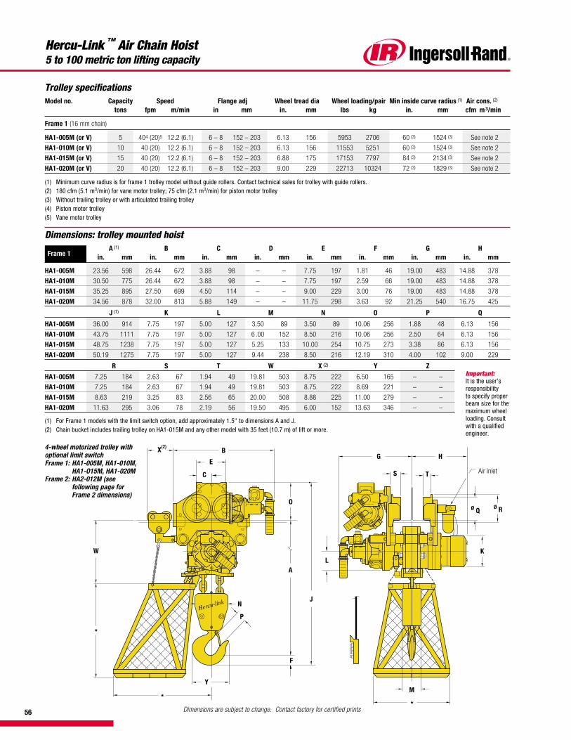
56
Hercu-Link ™ Air Chain Hoist5 to 100 metric ton lifting capacity
Dimensions: trolley mounted hoist
Frame 1A (1) B C D E F G H
in. mm in. mm in. mm in. mm in. mm in. mm in. mm in. mm
HA1-005M 23.56 598 26.44 672 3.88 98 – – 7.75 197 1.81 46 19.00 483 14.88 378
HA1-010M 30.50 775 26.44 672 3.88 98 – – 7.75 197 2.59 66 19.00 483 14.88 378
HA1-015M 35.25 895 27.50 699 4.50 114 – – 9.00 229 3.00 76 19.00 483 14.88 378
HA1-020M 34.56 878 32.00 813 5.88 149 – – 11.75 298 3.63 92 21.25 540 16.75 425
J (1) K L M N O P Q
HA1-005M 36.00 914 7.75 197 5.00 127 3.50 89 3.50 89 10.06 256 1.88 48 6.13 156
HA1-010M 43.75 1111 7.75 197 5.00 127 6 .00 152 8.50 216 10.06 256 2.50 64 6.13 156
HA1-015M 48.75 1238 7.75 197 5.00 127 5.25 133 10.00 254 10.75 273 3.38 86 6.13 156
HA1-020M 50.19 1275 7.75 197 5.00 127 9.44 238 8.50 216 12.19 310 4.00 102 9.00 229
R S T W X (2) Y Z
HA1-005M 7.25 184 2.63 67 1.94 49 19.81 503 8.75 222 6.50 165 – –
HA1-010M 7.25 184 2.63 67 1.94 49 19.81 503 8.75 222 8.69 221 – –
HA1-015M 8.63 219 3.25 83 2.56 65 20.00 508 8.88 225 11.00 279 – –
HA1-020M 11.63 295 3.06 78 2.19 56 19.50 495 6.00 152 13.63 346 – –
(1) For Frame 1 models with the limit switch option, add approximately 1.5" to dimensions A and J.(2) Chain bucket includes trailing trolley on HA1-015M and any other model with 35 feet (10.7 m) of lift or more.
N
P
F
Y
*
*
W
X(2)B
E
C
O
L
M
ø Q
Air inlet
G H
TS
ø R
K
A
J
*
4-wheel motorized trolley withoptional limit switchFrame 1: HA1-005M, HA1-010M,
HA1-O15M, HA1-020MFrame 2: HA2-012M (see
following page forFrame 2 dimensions)
Trolley specificationsModel no. Capacity Speed Flange adj Wheel tread dia Wheel loading/pair Min inside curve radius (1) Air cons. (2)
tons fpm m/min in mm in. mm lbs kg in. mm cfm m 3/min
Frame 1 (16 mm chain)
HA1-005M (or V) 5 404 (20)5 12.2 (6.1) 6 – 8 152 – 203 6.13 156 5953 2706 60 (3) 1524 (3) See note 2
HA1-010M (or V) 10 40 (20) 12.2 (6.1) 6 – 8 152 – 203 6.13 156 11553 5251 60 (3) 1524 (3) See note 2
HA1-015M (or V) 15 40 (20) 12.2 (6.1) 6 – 8 152 – 203 6.88 175 17153 7797 84 (3) 2134 (3) See note 2
HA1-020M (or V) 20 40 (20) 12.2 (6.1) 6 – 8 152 – 203 9.00 229 22713 10324 72 (3) 1829 (3) See note 2
(1) Minimum curve radius is for frame 1 trolley model without guide rollers. Contact technical sales for trolley with guide rollers.(2) 180 cfm (5.1 m3/min) for vane motor trolley; 75 cfm (2.1 m3/min) for piston motor trolley(3) Without trailing trolley or with articulated trailing trolley(4) Piston motor trolley(5) Vane motor trolley
Important:It is the user’sresponsibilityto specify properbeam size for themaximum wheelloading. Consultwith a qualifiedengineer.
Dimensions are subject to change. Contact factory for certified prints
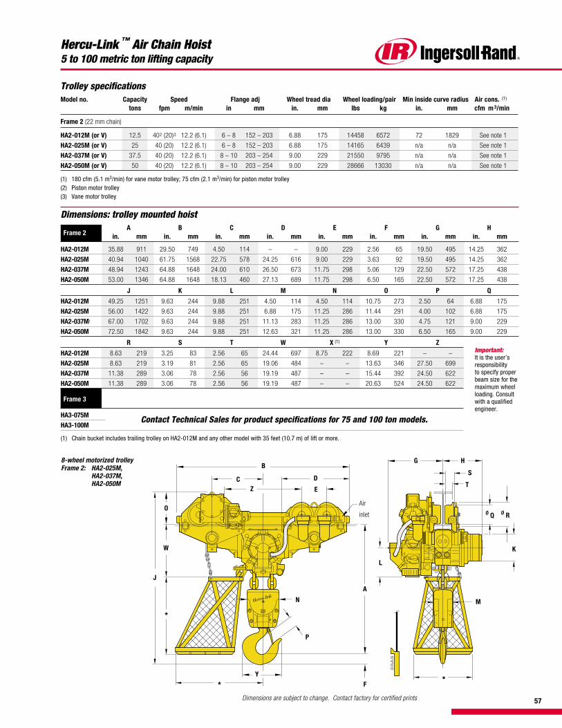
57
Hercu-Link ™ Air Chain Hoist5 to 100 metric ton lifting capacity
Dimensions: trolley mounted hoist
Frame 2A B C D E F G H
in. mm in. mm in. mm in. mm in. mm in. mm in. mm in. mm
HA2-012M 35.88 911 29.50 749 4.50 114 – – 9.00 229 2.56 65 19.50 495 14.25 362
HA2-025M 40.94 1040 61.75 1568 22.75 578 24.25 616 9.00 229 3.63 92 19.50 495 14.25 362
HA2-037M 48.94 1243 64.88 1648 24.00 610 26.50 673 11.75 298 5.06 129 22.50 572 17.25 438
HA2-050M 53.00 1346 64.88 1648 18.13 460 27.13 689 11.75 298 6.50 165 22.50 572 17.25 438
J K L M N O P Q
HA2-012M 49.25 1251 9.63 244 9.88 251 4.50 114 4.50 114 10.75 273 2.50 64 6.88 175
HA2-025M 56.00 1422 9.63 244 9.88 251 6.88 175 11.25 286 11.44 291 4.00 102 6.88 175
HA2-037M) 67.00 1702 9.63 244 9.88 251 11.13 283 11.25 286 13.00 330 4.75 121 9.00 229
HA2-050M 72.50 1842 9.63 244 9.88 251 12.63 321 11.25 286 13.00 330 6.50 165 9.00 229
R S T W X (1) Y Z
HA2-012M 8.63 219 3.25 83 2.56 65 24.44 697 8.75 222 8.69 221 – –
HA2-025M 8.63 219 3.19 81 2.56 65 19.06 484 – – 13.63 346 27.50 699
HA2-037M 11.38 289 3.06 78 2.56 56 19.19 487 – – 15.44 392 24.50 622
HA2-050M 11.38 289 3.06 78 2.56 56 19.19 487 – – 20.63 524 24.50 622
Frame 3
HA3-075M Contact Technical Sales for product specifications for 75 and 100 ton models.HA3-100M
(1) Chain bucket includes trailing trolley on HA2-012M and any other model with 35 feet (10.7 m) of lift or more.
8-wheel motorized trolleyFrame 2: HA2-025M,
HA2-037M,HA2-050M
G H
S
T
ø Q ø R
K
L
M
A
F*
*
B
C D
EZ
O
W
J
N
P
Y
Air
inlet
*
Trolley specificationsModel no. Capacity Speed Flange adj Wheel tread dia Wheel loading/pair Min inside curve radius Air cons. (1)
tons fpm m/min in mm in. mm lbs kg in. mm cfm m 3/min
Frame 2 (22 mm chain)
HA2-012M (or V) 12.5 402 (20)3 12.2 (6.1) 6 – 8 152 – 203 6.88 175 14458 6572 72 1829 See note 1
HA2-025M (or V) 25 40 (20) 12.2 (6.1) 6 – 8 152 – 203 6.88 175 14165 6439 n/a n/a See note 1
HA2-037M (or V) 37.5 40 (20) 12.2 (6.1) 8 – 10 203 – 254 9.00 229 21550 9795 n/a n/a See note 1
HA2-050M (or V) 50 40 (20) 12.2 (6.1) 8 – 10 203 – 254 9.00 229 28666 13030 n/a n/a See note 1
(1) 180 cfm (5.1 m3/min) for vane motor trolley; 75 cfm (2.1 m3/min) for piston motor trolley(2) Piston motor trolley(3) Vane motor trolley
Important:It is the user’sresponsibilityto specify properbeam size for themaximum wheelloading. Consultwith a qualifiedengineer.
Dimensions are subject to change. Contact factory for certified prints
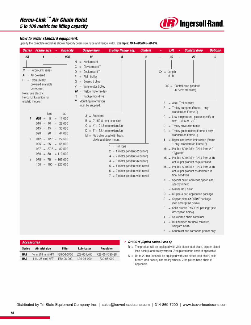
58
Hercu-Link ™ Air Chain Hoist5 to 100 metric ton lifting capacity
How to order standard equipment:Specify the complete model as shown. Specify beam size, type and flange width. Example: HA1-005MA3-30-27L
n S•COR•E (Option codes R and S)R = The product will be equipped with zinc plated load chain, copper plated
load hook(s) and trolley wheels. Zinc plated hand chain if applicable.
S = Up to 20 ton units will be equipped with zinc plated load chain, solidbronze load hook(s) and trolley wheels. Zinc plated hand chain ifapplicable.
A = Standard
B = 2" (50.8 mm) extension
C = 4" (101.6 mm) extension
D = 6" (152.4 mm) extension
M = No trolley used with hook,clevis and deck mount
Control
3
Suspension
MH = Hook mount
C = Clevis mount**
D = Deck mount**
P = Plain trolley
G = Geared trolley
V = Vane motor trolley
M = Piston motor trolley
R = Rack/pinion drive
** Mounting informationmust be supplied.
Series
HA
Frame size
1
Trolley flange adj.
A
H = Hercu-Link series
A = Air powered
H = Hydraulicallypowered availableon request
Note: See ElectricHercu-Link section forelectric models.
Capacity
005
Options
L
tons lbs.
005 = 5 = 11,000
010 = 10 = 22,000
015 = 15 = 33,000
020 = 20 = 44,000
012 = 12.5 = 27,500
025 = 25 = 55,000
037 = 37.5 = 82,500
050 = 50 = 110,000
075 = 75 = 165,000
100 = 100 = 220,000
1
2
3
Lift
30
1 = Pull rope
2 = 1 motor pendent (2 button)
3 = 2 motor pendent (4 button)
4 = 3 motor pendent (6 button)
5 = 1 motor pendent with on/off
6 = 2 motor pendent with on/off
7 = 3 motor pendent with on/off
XX = Lengthof lift
Control drop
27
XX = Control drop pendent(6 ft/2m standard)
-
-
-
-
-
-
A = Accu-Trol pendent
B = Trolley bumpers (Frame 1 only;standard on Frame 2)
C = Low temperature; please specify intext: -10˚ C or -20˚ C
D = Trolley drive disc brake
G = Trolley guide rollers (Frame 1 only;standard on Frame 2)
L = Upper and lower limit switch (Frame1 only; standard on Frame 2)
M1 = Per DIN 50049/En10204 Para 2.2“Typicals”
M2 = Per DIN 50049/En10204 Para 3.1bactual per product as purchased
M3 = Per DIN 50049/En10204 Para 3.1bactual per product as delivered infinal condition
N = Special paint; add code option andspecify in text
P = Marine 812 finish
Q = 60 psi (4 bar) application package
R = Copper plate S•COR•E package(see description below)
S = Solid bronze S•COR•E package (seedescription below)
T = Galvanized chain container
Y = Hull bumper (for hook mountedshipyard hoist)
Z = Sandblast and carbozinc primer only
Accessories
Series Air inlet size Filter Lubricator Regulator
HA1 3⁄4 in. (19 mm) NPT F28-06-SK00 L28-06-LK00 R28-06-F0G0-28HA2 1 in. (25 mm) NPT F30-08-000 L30-08-000 R30-08-G00
Distributed by Tri-State Equipment Company Inc. | [email protected] | 314-869-7200 | www.tsoverheadcrane.com
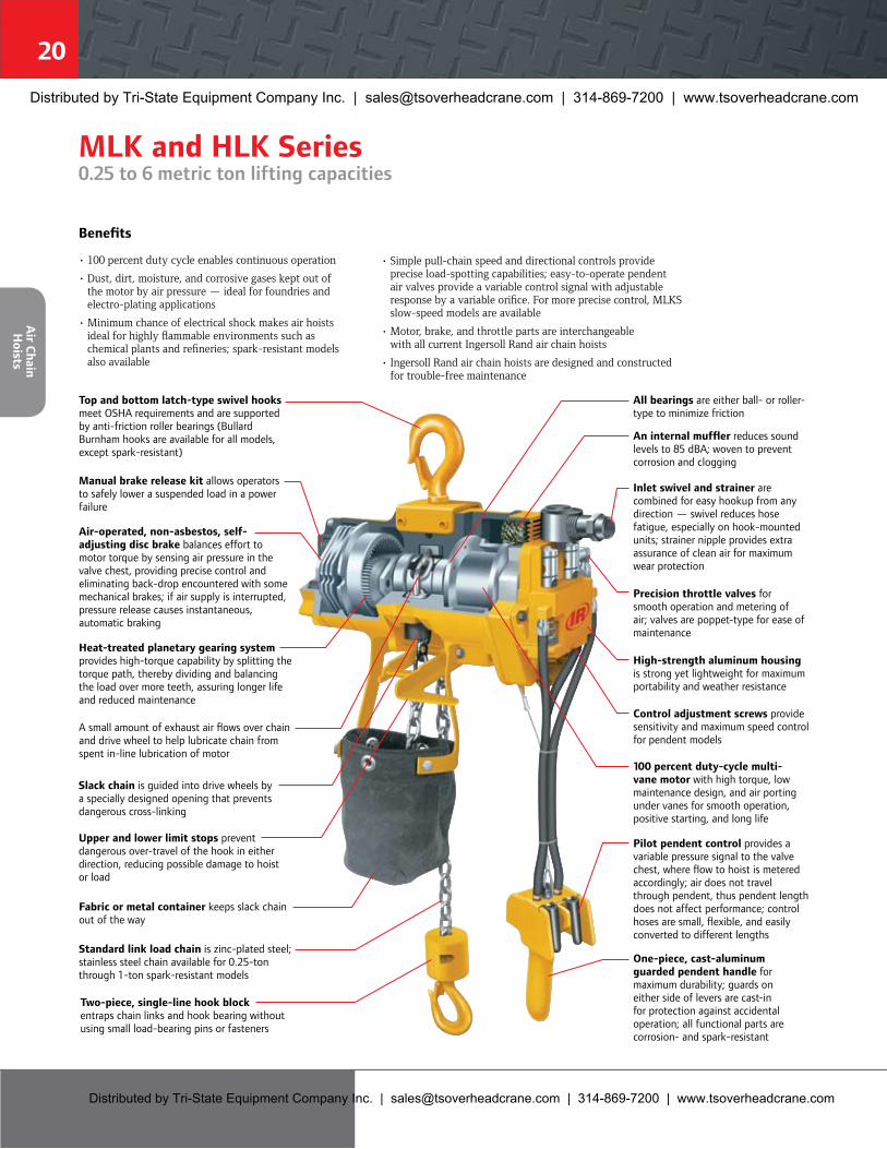
Distributed by Tri-State Equipment Company Inc. | [email protected] | 314-869-7200 | www.tsoverheadcrane.com
Distributed by Tri-State Equipment Company Inc. | [email protected] | 314-869-7200 | www.tsoverheadcrane.com


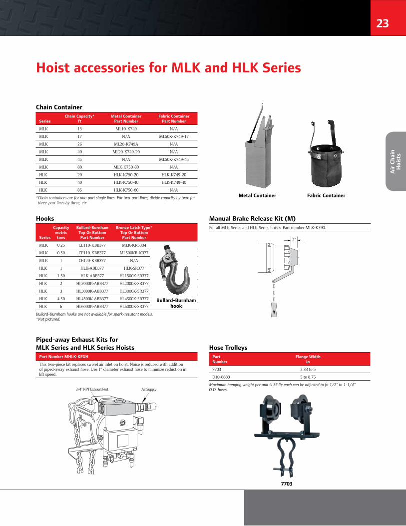
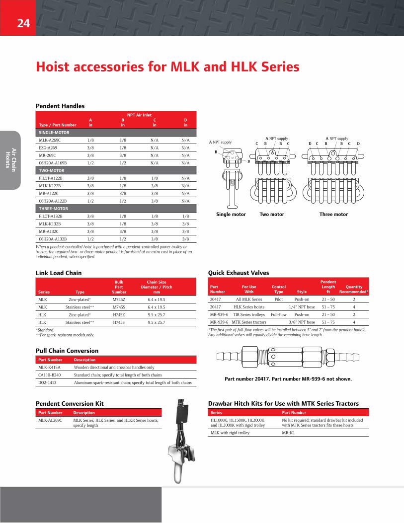
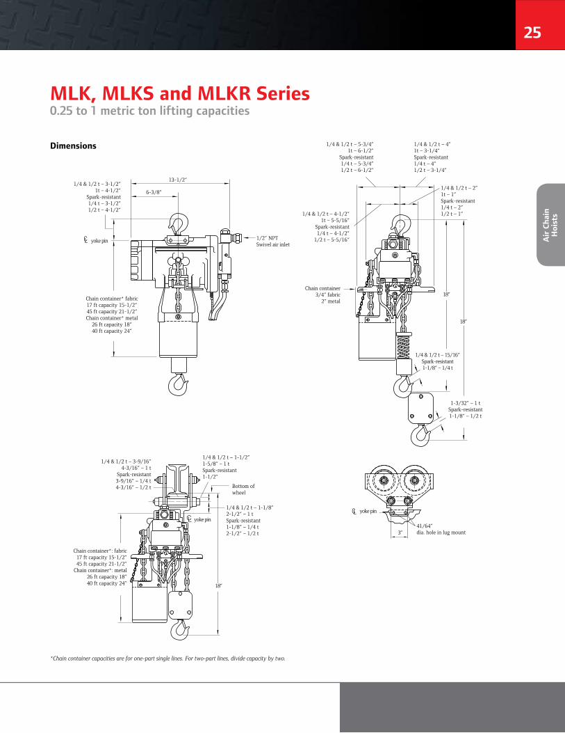
CL
CL
CL


Distributed by Tri-State Equipment Company Inc.Email: [email protected]
Web: www.tsoverheadcrane.comPH: 314-869-7200 | FAX: 314-869-7226
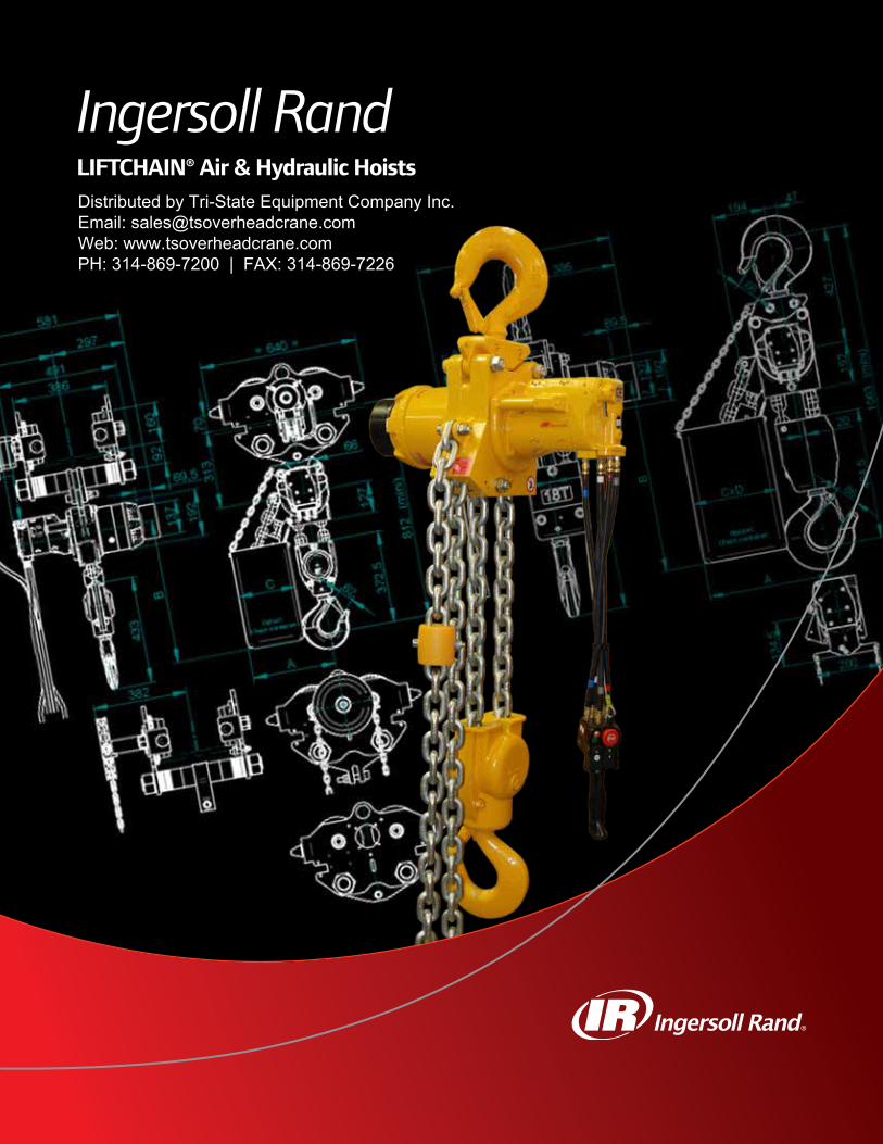
Ingersoll RandLIFTCHAIN® Air & Hydraulic HoistsDistributed by Tri-State Equipment Company Inc.Email: [email protected]: www.tsoverheadcrane.comPH: 314-869-7200 | FAX: 314-869-7226
1
ContentsLIFTCHAIN® Air Chain Hoists .............................................2Available in hook, standard and low headroom trolley mount configurations, these hoists are ideal for hazardous or high duty cycle applications. Experience-proven features and safety enhancements include exclusive air gear motor, automatic fail-safe brakes, corrosion resistant load chain, spark resistant packages, overload protection and E-stops along with CE compliant packages.
LIFTCHAIN® Hydraulic Chain Hoists ...............................13Providing the exceptionally smooth and precise control that hydraulics offer the LCH series of hoists and trolleys are available in hook and standard or low headroom trolley configura-tions. Hydraulic motors and controls are particularly well suited for integration with complex programmable logic control (PLC) systems and other automated applications.
How To Order ...................................................................22Detailed model driver chart to direct you through the creation of the LIFTCHAIN® part number creation
Service & Accessories .......................................................23Ingersoll Rand offers a full line of accessories and service solutions beginning with simple repair and maintenance kits and extending to complete on-site inspections, maintenance, and training provided by factory trained technicians anywhere in the world.
Solutions ..........................................................................32Ingersoll Rand believes solutions begin with the specification of a product or service to meet your specific applications requirements and then continues through the products’ entire lifecycle. We have over 100 years of experience in providing safe and cost effective lifting solutions.
Winch & Hoist Checklist ..................................................33A comprehensive checklist to assist us in providing the best product or service to meet your applications specific requirements.
WARNING: Unless otherwise noted this equipment is not designed for transporting people or lifting loads over people. It is the user’s responsibility to determine the suitability of this product for any particular use and to check compliance with applicable regulations. Before installation, see maintenance and operations manual for additional warnings and precautions.

2
LIFTCHAIN® Air Chain Hoists
Ingersoll Rand has over 40 years of experience in heavy load lifting applications in the most difficult and extreme environments around the world. The new range of LIFTCHAIN® LC2A series hoists incorporates the best of what we have learned over this time.
Featuring a compact, robust and modular design, the LIFTCHAIN® hoists offer a range of capacities from 1.5 to 100 metric tons with a variety of configurations including hook mount or with plain, geared, or motorized trolleys for mounting on jibs or beams.
Experience drives features and options, and four decades of experience means we have plenty of both to choose from; Chain containers, CE approved models, cold weather designs, spark and corrosion resistant versions, 5: 1 design factors, articulating trolleys, custom control systems, and low headroom models; the list goes on.
Whether it’s lifting bags of farm produce or carefully positioning a 100 ton piece of equipment on a North Sea oil platform, we have the hoisting system to get the job done on time, every time, and at cost-effective price.
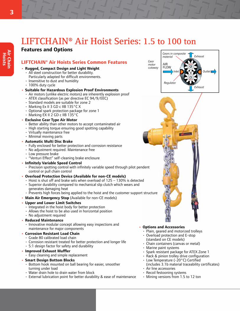
3
LIFTCHAIN® Air Hoist Series: 1.5 to 100 tonFeatures and OptionsA
ir Chain H
oists LIFTCHAIN® Air Hoists Series Common Features• Rugged, Compact Design and Light Weight • All steel construction for better durability. Particularly adapted for difficult environments. • Insensitive to dust and humidity • 100% duty cycle• Suitable for Hazardous Explosion Proof Environments • Air motors (unlike electric motors) are inherently explosion proof • ATEX classification (as per directive EC 94/9/EEC) • Standard models are suitable for zone 2 • Marking Ex II 3 GD c IIB 135°C X • Optional spark protection package for zone 1 • Marking EX II 2 GD c IIB 135°C• Exclusive Gear Type Air Motor • Better ability than other motors to accept contaminated air • High starting torque ensuring good spotting capability • Virtually maintenance free • Minimal moving parts• Automatic Multi Disc Brake • Fully enclosed for better protection and corrosion resistance • No adjustment required. Maintenance free • Low pressure brake • “Venturi Effect” self-cleaning brake enclosure• Infinitely Variable Speed Control • Precision spotting control with infinitely variable speed through pilot pendent control or pull chain control• Overload Protection Device (Available for non-CE models) • Hoist is shut off and brake sets when overload of 125 – 130% is detected • Superior durability compared to mechanical slip clutch which wears and generates damaging heat • Prevents high forces being applied to the hoist and the customer support structure• Main Air Emergency Stop (Available for non-CE models)• Upper and Lower Limit Switches • Integrated in the hoist body for better protection • Allows the hoist to be also used in horizontal position • No adjustment required• Reduced Maintenance • Innovative modular concept allowing easy inspections and maintenance for major components• Corrosion Resistant Load Chain • Grade 80 calibrated load chain • Corrosion resistant treated for better protection and longer life • 5:1 design factor for safety and durability• Improved Exhaust Muffler • Easy cleaning and simple replacement• Smart Design Bottom Blocks • Bottom hook mounted on ball bearing for easier, smoother turning under load • Water drain hole to drain water from block • External lubrication point for better durability & ease of maintenance
Gear motor cutaway
Gears in compositematerial
Regulator
Exhaust
Exhaust
OutletInlet
AIRFLOW
• Options and Accessories • Plain, geared and motorized trolleys • Overload protection and E-stop (standard on CE models) • Chain containers (canvas or metal) • Marine paint systems • Spark resistant package for ATEX Zone 1 • Rack & pinion trolley drive configuration • Low Temperature (-20°C) Certified (includes 3.1b material traceability certificates) • Air line accessories • Recoil festooning systems • Mining versions from 1.5 to 12 ton
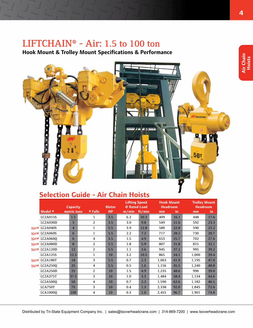
4
Air
Cha
in
Hoi
sts
LIFTCHAIN® - Air: 1.5 to 100 tonHook Mount & Trolley Mount Specifications & Performance
Selection Guide - Air Chain HoistsLifting Speed Hook Mount Trolley Mount
Capacity Motor @ Rated Load Headroom Headroom Model # metric tons # Falls HP m/min ft/min mm in mm inLC2A015S 1.5 1 3.5 6.2 20.3 409 16.1 448 17.6
LC2A030D 3 2 3.5 3.0 9.8 549 21.6 592 23.3
LC2A040S 4 1 5.5 3.9 12.8 580 22.8 590 23.2
LC2A060S 6 1 5.5 2.2 7.2 717 28.2 730 28.7
LC2A060Q 6 4 3.5 1.5 4.9 653 25.7 702 27.6
LC2A080D 8 2 5.5 1.8 5.9 807 31.8 815 32.1
LC2A120D 12 2 5.5 1.1 3.6 945 37.2 995 39.2
LC2A125S 12.5 1 10 3.2 10.5 865 34.1 1,000 39.4
LC2A180T 18 3 5.5 0.7 2.3 1,063 41.9 1,195 47.0
LC2A250Q 25 4 5.5 0.5 1.6 1,156 45.5 1,240 48.8
LC2A250D 25 2 10 1.5 4.9 1,235 48.6 990 39.0
LC2A375T 37.5 3 10 1.0 3.3 1,484 58.4 1,134 44.6
LC2A500Q 50 4 10 0.7 2.3 1,590 62.6 1,182 46.5
LCA750T 75 3 10 0.4 1.3 2,338 92.0 1,845 72.6
LCA1000Q 100 4 10 0.3 1.0 2,455 96.7 1,901 74.8
New
NewNew
NewNewNewNew
Distributed by Tri-State Equipment Company Inc. | [email protected] | 314-869-7200 | www.tsoverheadcrane.com
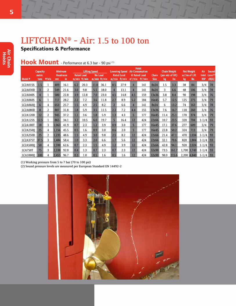
5
Air Chain H
oists
LIFTCHAIN® - Air: 1.5 to 100 tonSpecifications & Performance
Hook Mount - Performance at 6.3 bar - 90 psi (1)
HoistCapacity Minimum Lifting Speed Lowering Speed Air Consumption Chain Weight Net Weight Air Soundmetric Headroom Rated Load No Load Rated Load @ Rated Load Chain (per mtr of lift) w/3m of Lift Inlet Level(2)
Model # tons #Falls mm in m/min ft/min m/min ft/min m/min ft/min m3/min ft3/min Size kg lbs kg lbs BSP dB(A)
LC2A015S 1.5 1 409 16.1 6.2 20.3 11.0 36.1 8.5 27.9 4 141 8x24 1.5 3.3 38 84 3/4 78
LC2A030D 3 2 549 21.6 3.0 9.8 5.5 18.0 4 13.1 4 141 8x24 3 6.6 48 106 3/4 78
LC2A040S 4 1 580 22.8 3.9 12.8 7.0 23.0 4.5 14.8 4.5 159 13x36 3.8 8.4 90 198 3/4 76
LC2A060S 6 1 717 28.2 2.2 7.2 3.6 11.8 2.7 8.9 5.2 184 16x45 5.7 12.5 125 275 3/4 79
LC2A060Q 6 4 653 25.7 1.5 4.9 2.5 8.2 2 6.6 4 141 8x24 6 13.2 74 163 3/4 78
LC2A080D 8 2 807 31.8 1.8 5.9 3.5 11.5 2.2 7.2 4.4 155 13x36 7.6 16.7 118 260 3/4 76
LC2A120D 12 2 945 37.2 1.1 3.6 1.8 5.9 1.3 4.3 5 177 16x45 11.4 25.1 170 374 3/4 79
LC2A125S 12.5 1 865 34.1 3.2 10.5 6.0 19.7 5 16.4 12 424 22x66 10.7 23.5 320 704 1-1/4 93
LC2A180T 18 3 1,063 41.9 0.7 2.3 1.2 3.9 0.9 3.0 5 177 16x45 17.1 37.6 277 609 3/4 79
LC2A250Q 25 4 1,156 45.5 0.5 1.6 0.9 3.0 0.6 2.0 5 177 16x45 22.8 50.2 324 713 3/4 79
LC2A250D 25 2 1,235 48.6 1.5 4.9 3.0 9.8 2.5 8.2 12 424 22x66 21.4 47.1 470 1,034 1-1/4 93
LC2A375T 37.5 3 1,484 58.4 1.0 3.3 2.0 6.6 1.7 5.6 12 424 22x66 32.1 70.6 820 1,804 1-1/4 93
LC2A500Q 50 4 1,590 62.6 0.7 2.3 1.5 4.9 1.2 3.9 12 424 22x66 42.8 94.1 920 2,024 1-1/4 93
LCA750T 75 3 2,338 92.0 0.4 1.3 0.7 2.3 0.7 2.3 12 424 32x90 73.5 161.7 1,700 3,740 1-1/4 93
LCA1000Q 100 4 2,455 96.7 0.3 1.0 0.5 1.6 0.5 1.6 12 424 32x90 98.0 215.6 2,200 4,840 1-1/4 93
(1) Working pressure from 5 to 7 bar (70 to 100 psi)(2) Sound pressure levels are measured per European Standard EN 14492-2

6
(1) For Low Headroom version, see page 11(2) Working pressure from 5 to 7 bar (70 to 100 psi)(3) In Rack & Pinion configuration, the trolley speed is divided by two(*) 200-310 with Option W
Working pressure range = x to y, (1) Hoist and trolley- 3 m of lift and 2 m of control drop. Trolley Air Trolley Minimum Net WeightMinimum Trolley Speed Consumption Flange Curve Air w/3m of
Trolley Capacity Headroom @ Rated Load (3) @ Rated Load Adjustment Radius Inlet Lift Model # Type metric tons mm in m/min ft/min m3/min ft3/min mm in m ft BSP kg lbsLC2A015S Plain 1.5 448 17.6 - - - - 80-200* 3.1-7.9 1 3.3 - 90 198
LC2A015S Geared 1.5 448 17.6 - - - - 80-200* 3.1-7.9 1 3.3 - 92 202
LC2A015S Motor 1.5 448 17.6 17 55.8 1.3 46 80-200* 3.1-7.9 1 3.3 3/4 95 209
LC2A030D Plain 3 592 23.3 - - - - 80-200* 3.1-7.9 2 6.6 - 98 216
LC2A030D Geared 3 592 23.3 - - - - 80-200* 3.1-7.9 2 6.6 - 100 220
LC2A030D Motor 3 592 23.3 17 55.8 1.3 46 80-200* 3.1-7.9 2 6.6 3/4 103 227
LC2A040S Plain 4 590 23.2 - - - - 80-200* 3.1-7.9 2 6.6 - 140 308
LC2A040S Geared 4 590 23.2 - - - - 80-200* 3.1-7.9 2 6.6 - 142 312
LC2A040S Motor 4 590 23.2 15 49.2 1.3 46 80-200* 3.1-7.9 2 6.6 3/4 145 319
LC2A060S Plain 6 730 28.7 - - - - 100-310 3.9-12.2 3 9.8 - 250 550
LC2A060S Geared 6 730 28.7 - - - - 100-310 3.9-12.2 3 9.8 - 257 565
LC2A060S Motor 6 730 28.7 15 49.2 1.3 46 100-310 3.9-12.2 3 9.8 3/4 267 587
LC2A060Q Plain 6 702 27.6 - - - - 100-310 3.9-12.2 3 9.8 - 200 440
LC2A060Q Geared 6 702 27.6 - - - - 100-310 3.9-12.2 3 9.8 - 207 455
LC2A060Q Motor 6 702 27.6 15 49.2 1.3 46 100-310 3.9-12.2 3 9.8 3/4 217 477
LC2A080D Plain 8 815 32.1 - - - - 100-310 3.9-12.2 3 9.8 - 243 535
LC2A080D Geared 8 815 32.1 - - - - 100-310 3.9-12.2 3 9.8 - 250 550
LC2A080D Motor 8 815 32.1 12 39.4 1.3 46 100-310 3.9-12.2 3 9.8 3/4 260 572
LC2A120D Plain 12 995 39.2 - - - - 130-310 5.1-12.2 3 9.8 - 335 737
LC2A120D Geared 12 995 39.2 - - - - 130-310 5.1-12.2 3 9.8 - 343 755
LC2A120D Motor 12 995 39.2 12 39.4 1.9 67 130-310 5.1-12.2 3 9.8 3/4 352 774
LC2A125S Motor 12.5 1,000 39.4 12 39.4 1.9 67 130-310 5.1-12.2 3 9.8 1-1/4 570 1,256
LC2A180T Plain 18 1,195 47.0 - - - - 140-310 5.5-12.2 5 16.4 - 652 1,434
LC2A180T Geared 18 1,195 47.0 - - - - 140-310 5.5-12.2 5 16.4 - 660 1,452
LC2A180T Motor 18 1,195 47.0 15 49.2 1.9 67 140-310 5.5-12.2 5 16.4 3/4 669 1,472
LC2A250Q Plain 25 1,240 48.8 - - - - 140-310 5.5-12.2 5 16.4 - 700 1,540
LC2A250Q Geared 25 1,240 48.8 - - - - 140-310 5.5-12.2 5 16.4 - 708 1,558
LC2A250Q Motor 25 1,240 48.8 12 39.4 1.9 67 140-310 5.5-12.2 5 16.4 3/4 717 1,577
LC2A250D Motor 25 990 39.0 12 39.4 1.9 67 140-310 5.5-12.2 5 16.4 1-1/4 845 1,859
LC2A375T Motor 37.5 1,134 44.6 15 49.2 3.8 134 160-310 6.3-12.2 25 82.0 1-1/4 1,650 3,630
LC2A500Q Motor 50 1,182 46.5 12 39.4 3.8 134 160-310 6.3-12.2 25 82.0 1-1/4 1,950 4,290
LCA750T Motor 75 1,845 72.6 10 32.8 7.6 268 160-310 6.3-12.2 130 426.4 1-1/4 4,500 9,900
LCA1000Q Motor 100 1,901 74.8 10 32.8 7.6 268 160-310 6.3-12.2 130 426.4 1-1/4 4,700 10,340
Trolley Mount - Performance at 6.3 bar - 90 psi (2)
Air
Cha
in
Hoi
sts
LIFTCHAIN® - Air: 1.5 to 100 tonSpecifications & Performance - Standard Headroom (1)

7
Air Chain H
oists
Dimension Drawings - Air: 1.5 to 25 ton (4 falls)Hook Mount
H
J
K
B
E
F
A (min)
C
C
ø
L
D
G
M
A B C D E F G H Hook Mount mm in mm in mm in mm in mm in mm in mm in mm inLC2A015S 409 16.1 112 4.4 27 1.1 173 6.8 90 3.5 146 5.7 30 1.2 425 16.7LC2A030D 549 21.6 112 4.4 35 1.4 202 8.0 90 3.5 257 10.1 37 1.5 425 16.7LC2A040S 580 22.8 183 7.2 35 1.4 264 10.4 127 5.0 190 7.5 37 1.5 606 23.9LC2A060S 717 28.2 233 9.2 43 1.7 350 13.8 139 5.5 228 9.0 50 2.0 630 24.8LC2A060Q 653 25.7 112 4.4 43 1.7 266 10.5 90 3.5 296 11.7 50 2.0 394 15.5LC2A080D 807 31.8 140 5.5 53 2.1 307 12.1 127 5.0 373 14.7 60 2.4 606 23.9LC2A120D 945 37.2 175 6.9 58 2.3 370 14.6 152 6.0 424 16.7 67 2.6 630 24.8LC2A125S 865 34.1 276 10.9 58 2.3 368 14.5 200.5 7.9 296 11.7 67 2.6 816 32.1LC2A180T 1,063 41.9 175 6.9 78 3.1 427 16.8 152 6.0 484 19.1 80 3.1 750 29.5LC2A250Q 1,156 45.5 175 6.9 87 3.4 474 18.7 152 6.0 530 20.9 96 3.8 750 29.5
J K L M Hook Mount mm in mm in mm in mm inLC2A015S 127 5.0 128 5.0 176 6.9 22 0.9LC2A030D 127 5.0 128 5.0 294 11.6 32 1.3LC2A040S 297 11.7 192 7.6 227 8.9 32 1.3LC2A060S 310 12.2 192 7.6 278 10.9 39 1.5LC2A060Q 158 6.2 128 5.0 346 13.6 39 1.5LC2A080D 297 11.7 192 7.6 433 17.0 55 2.2LC2A120D 310 12.2 192 7.6 491 19.3 57 2.2LC2A125S 265 10.4 300 11.8 363 14.3 57 2.2LC2A180T 386 15.2 192 7.6 564 22.2 67 2.6LC2A250Q 367 14.4 192 7.6 626 24.6 85 3.3
See page 27 for chainbucket
dimension information
Dimensions are subject to change, contact Customer Services for certified prints.

8
B C H
D
A
FJ
K
L
G M
E
Dimension Drawings - Air: 25 (double falls) to 100 tonHook Mount
A B C D E F G H J Hook Mount mm in mm in mm in mm in mm in mm in mm in mm in mm inLC2A250D 1,235 48.6 551 21.7 265 10.4 340 13.4 87 3.4 441 17.4 475 18.7 80 3.1 390.5 15.4
LC2A375T 1,484 58.4 605 23.8 373 14.7 390 15.4 103 4.1 441 17.4 475 18.7 125 4.9 406.5 16.0
LC2A500Q 1,590 62.6 632 24.9 346 13.6 440 17.3 118 4.6 441 17.4 475 18.7 140 5.5 415.5 16.4
LCA750T 2,338 92.0 632 24.9 718 28.3 574 22.6 152 6.0 441 17.4 912 35.9 180 7.1 774 30.5
LCA1000Q 2,455 96.7 668 26.3 682 26.9 610 24.0 180 7.1 441 17.4 912 35.9 200 7.9 774 30.5
K L M Hook Mount mm in mm in mm inLC2A250D 572 22.5 94 3.7 836 32.9
LC2A375T 714 28.1 132 5.2 836 32.9
LC2A500Q 763 30.0 150 5.9 836 32.9
LCA750T 1,055 41.5 190 7.5 1,165 45.9
LCA1000Q 1,111 43.7 250 9.8 1,365 53.7
Air
Cha
in
Hoi
sts
See page 27 for chainbucket
dimension information
Dimensions are subject to change, contact Customer Services for certified prints.
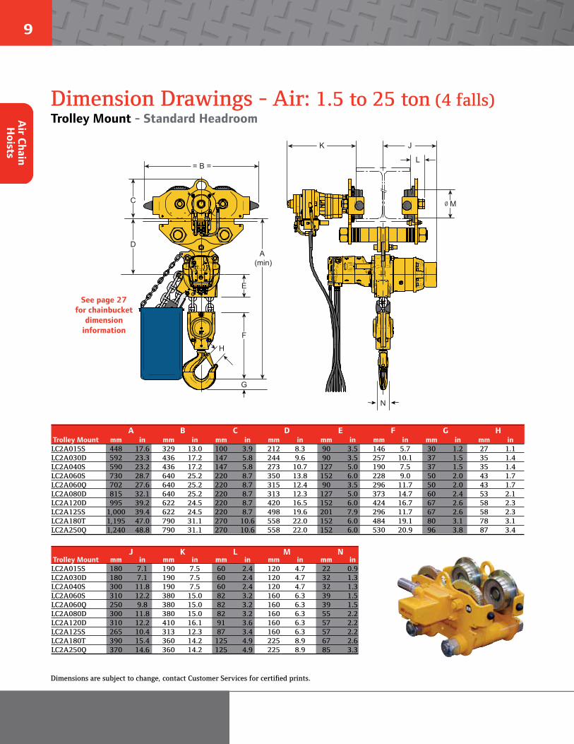
9
Dimension Drawings - Air: 1.5 to 25 ton (4 falls)Trolley Mount - Standard Headroom
H
C
D
E
F
= B =
A (min)
G
JK
L
Mø
N
A B C D E F G H Trolley Mount mm in mm in mm in mm in mm in mm in mm in mm inLC2A015S 448 17.6 329 13.0 100 3.9 212 8.3 90 3.5 146 5.7 30 1.2 27 1.1LC2A030D 592 23.3 436 17.2 147 5.8 244 9.6 90 3.5 257 10.1 37 1.5 35 1.4LC2A040S 590 23.2 436 17.2 147 5.8 273 10.7 127 5.0 190 7.5 37 1.5 35 1.4LC2A060S 730 28.7 640 25.2 220 8.7 350 13.8 152 6.0 228 9.0 50 2.0 43 1.7LC2A060Q 702 27.6 640 25.2 220 8.7 315 12.4 90 3.5 296 11.7 50 2.0 43 1.7LC2A080D 815 32.1 640 25.2 220 8.7 313 12.3 127 5.0 373 14.7 60 2.4 53 2.1LC2A120D 995 39.2 622 24.5 220 8.7 420 16.5 152 6.0 424 16.7 67 2.6 58 2.3LC2A125S 1,000 39.4 622 24.5 220 8.7 498 19.6 201 7.9 296 11.7 67 2.6 58 2.3LC2A180T 1,195 47.0 790 31.1 270 10.6 558 22.0 152 6.0 484 19.1 80 3.1 78 3.1LC2A250Q 1,240 48.8 790 31.1 270 10.6 558 22.0 152 6.0 530 20.9 96 3.8 87 3.4
J K L M N Trolley Mount mm in mm in mm in mm in mm inLC2A015S 180 7.1 190 7.5 60 2.4 120 4.7 22 0.9LC2A030D 180 7.1 190 7.5 60 2.4 120 4.7 32 1.3LC2A040S 300 11.8 190 7.5 60 2.4 120 4.7 32 1.3LC2A060S 310 12.2 380 15.0 82 3.2 160 6.3 39 1.5LC2A060Q 250 9.8 380 15.0 82 3.2 160 6.3 39 1.5LC2A080D 300 11.8 380 15.0 82 3.2 160 6.3 55 2.2LC2A120D 310 12.2 410 16.1 91 3.6 160 6.3 57 2.2LC2A125S 265 10.4 313 12.3 87 3.4 160 6.3 57 2.2LC2A180T 390 15.4 360 14.2 125 4.9 225 8.9 67 2.6LC2A250Q 370 14.6 360 14.2 125 4.9 225 8.9 85 3.3
See page 27 for chainbucket
dimension information
Air Chain H
oists
Dimensions are subject to change, contact Customer Services for certified prints.
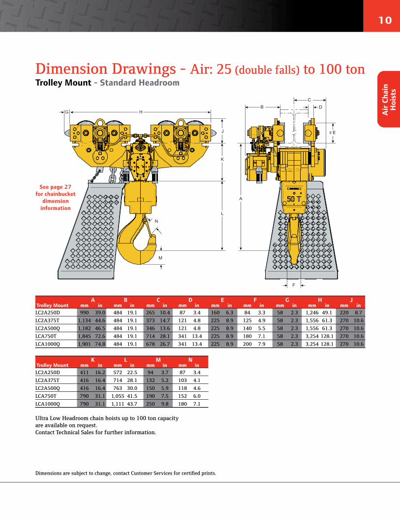
10
Air
Cha
in
Hoi
sts
Dimension Drawings - Air: 25 (double falls) to 100 tonTrolley Mount - Standard Headroom
L
K
M
N
D
ø E
C
H G
J
F
A
B
A B C D E F G H J Trolley Mount mm in mm in mm in mm in mm in mm in mm in mm in mm inLC2A250D 990 39.0 484 19.1 265 10.4 87 3.4 160 6.3 84 3.3 58 2.3 1,246 49.1 220 8.7
LC2A375T 1,134 44.6 484 19.1 373 14.7 121 4.8 225 8.9 125 4.9 58 2.3 1,556 61.3 270 10.6
LC2A500Q 1,182 46.5 484 19.1 346 13.6 121 4.8 225 8.9 140 5.5 58 2.3 1,556 61.3 270 10.6
LCA750T 1,845 72.6 484 19.1 714 28.1 341 13.4 225 8.9 180 7.1 58 2.3 3,254 128.1 270 10.6
LCA1000Q 1,901 74.8 484 19.1 678 26.7 341 13.4 225 8.9 200 7.9 58 2.3 3,254 128.1 270 10.6
K L M N Trolley Mount mm in mm in mm in mm inLC2A250D 411 16.2 572 22.5 94 3.7 87 3.4
LC2A375T 416 16.4 714 28.1 132 5.2 103 4.1
LC2A500Q 416 16.4 763 30.0 150 5.9 118 4.6
LCA750T 790 31.1 1,055 41.5 190 7.5 152 6.0
LCA1000Q 790 31.1 1,111 43.7 250 9.8 180 7.1
See page 27 for chainbucket
dimension information
Ultra Low Headroom chain hoists up to 100 ton capacity are available on request. Contact Technical Sales for further information.
Dimensions are subject to change, contact Customer Services for certified prints.

11
LIFTCHAIN® - Air: 1.5 to 25 tonSpecifications & Performance - Low Headroom
Building rugged and compact hoisting equipment to fit into cramped, confined, and inhospitable spaces is a specialty of Ingersoll Rand.
Our Low and Ultra-Low™ hoisting systems are used in applications where space is at a premium and en-vironments are challenging; offshore oil platforms, underground mining and tunneling, gas processing modules, and shipboard engine rooms.
(1) Working pressure from 5 to 7 bar (70 to 100 psi)(*) 200-310 with Option W
Air Chain H
oists
Working pressure range = x to y, (1) Hoist and trolley- 3 m of lift and 2 m of control drop. Air TrolleyMinimum Trolley Speed Consumption Flange Minimum Air
Trolley Capacity Headroom @ Rated Load @ Rated Load Adjustment Curve Inlet Model # Type metric tons mm in m/min ft/min m3/min ft3/min mm in Radius BSP
LC2A015S Motor 1.5 285 11.2 17 55.8 1.3 46 82-200 3.2-7.9 NA 3/4 LC2A030D Motor 3 396 15.6 17 55.8 1.3 46 80-200* 3.2-7.9 NA 3/4 LC2A040S Motor 4 382 15 15 49.2 1.3 46 80-200* 3.1-7.9 NA 1 LC2A060S Motor 6 443 17.4 12 39.4 1.9 67 100-310 3.9-12.2 NA 1 LC2A060Q Motor 6 695 27.4 15 49.2 1.3 46 100-310 3.9-12.2 NA 3/4 LC2A080D Motor 8 521 20.5 12 39.4 1.3 46 100-310 3.9-12.2 NA 1 LC2A120D Motor 12 638 25.1 12 39.4 1.9 67 140-310 5.5-12.2 10 1 LC2A180T Motor 18 688 27.1 12 39.4 1.9 67 200-310 7.9-12.2 NA 1 LC2A250Q Motor 25 740 29.1 12 39.4 1.9 67 170-310 6.7-12.2 10 1
Low Headroom Motorized Trolley - Performance at 6.3 bar - 90 psi (1)
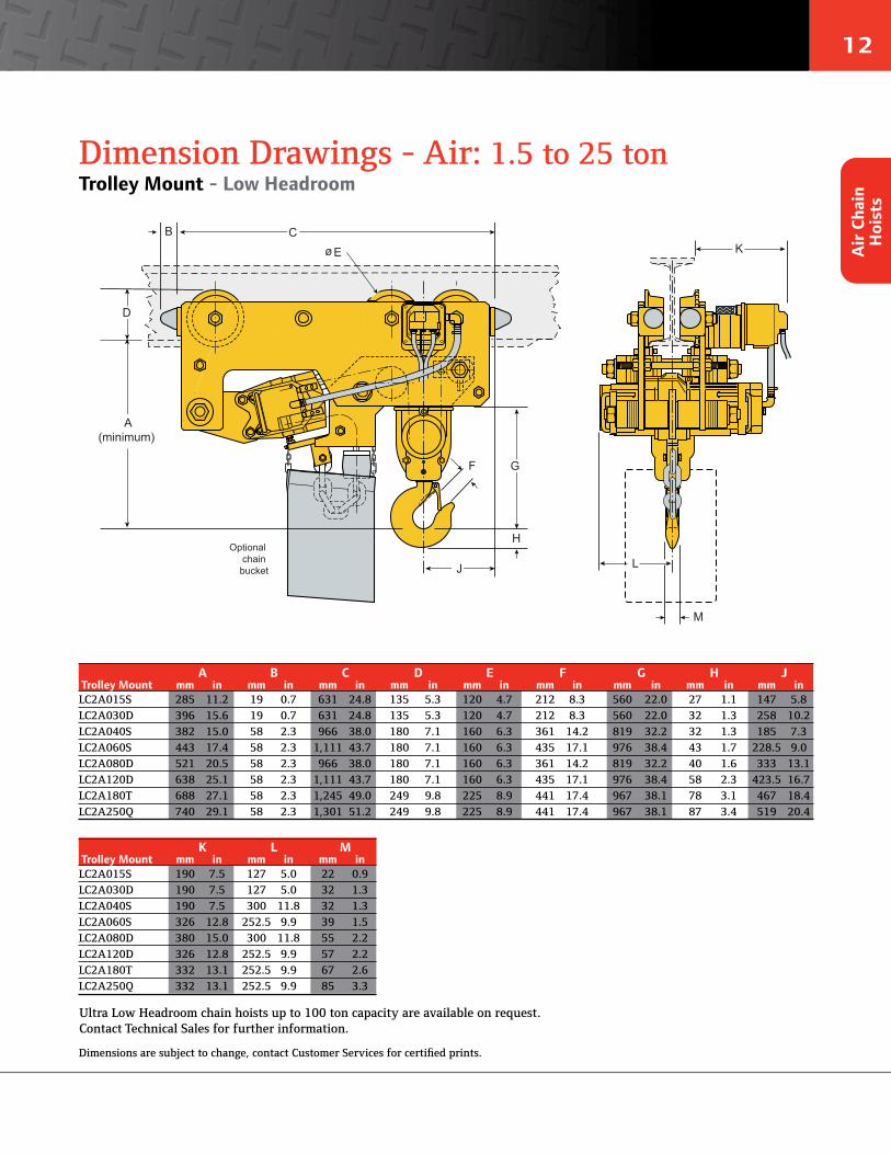
12
Dimension Drawings - Air: 1.5 to 25 tonTrolley Mount - Low Headroom
Optional chain
bucket
C K
J L
M
B
ø E
A(minimum)
D
G
H
F
A B C D E F G H J Trolley Mount mm in mm in mm in mm in mm in mm in mm in mm in mm inLC2A015S 285 11.2 19 0.7 631 24.8 135 5.3 120 4.7 212 8.3 560 22.0 27 1.1 147 5.8LC2A030D 396 15.6 19 0.7 631 24.8 135 5.3 120 4.7 212 8.3 560 22.0 32 1.3 258 10.2LC2A040S 382 15.0 58 2.3 966 38.0 180 7.1 160 6.3 361 14.2 819 32.2 32 1.3 185 7.3LC2A060S 443 17.4 58 2.3 1,111 43.7 180 7.1 160 6.3 435 17.1 976 38.4 43 1.7 228.5 9.0LC2A080D 521 20.5 58 2.3 966 38.0 180 7.1 160 6.3 361 14.2 819 32.2 40 1.6 333 13.1LC2A120D 638 25.1 58 2.3 1,111 43.7 180 7.1 160 6.3 435 17.1 976 38.4 58 2.3 423.5 16.7LC2A180T 688 27.1 58 2.3 1,245 49.0 249 9.8 225 8.9 441 17.4 967 38.1 78 3.1 467 18.4LC2A250Q 740 29.1 58 2.3 1,301 51.2 249 9.8 225 8.9 441 17.4 967 38.1 87 3.4 519 20.4
K L M Trolley Mount mm in mm in mm inLC2A015S 190 7.5 127 5.0 22 0.9LC2A030D 190 7.5 127 5.0 32 1.3LC2A040S 190 7.5 300 11.8 32 1.3LC2A060S 326 12.8 252.5 9.9 39 1.5LC2A080D 380 15.0 300 11.8 55 2.2LC2A120D 326 12.8 252.5 9.9 57 2.2LC2A180T 332 13.1 252.5 9.9 67 2.6LC2A250Q 332 13.1 252.5 9.9 85 3.3
Air
Cha
in
Hoi
sts
Ultra Low Headroom chain hoists up to 100 ton capacity are available on request. Contact Technical Sales for further information.
Dimensions are subject to change, contact Customer Services for certified prints.

13
• The LIFTCHAIN® Hydraulic Chain Hoist series is an innovative alternative to ourair driven chain hoists. Capacities from 6 to 100 metric ton.
• Very low noise level
• Extremely sensitive variable speed control of lifting and travelling motions
• Easy installation and operation
• Lower energy cost
LIFTCHAIN® Hydraulic Chain Hoists
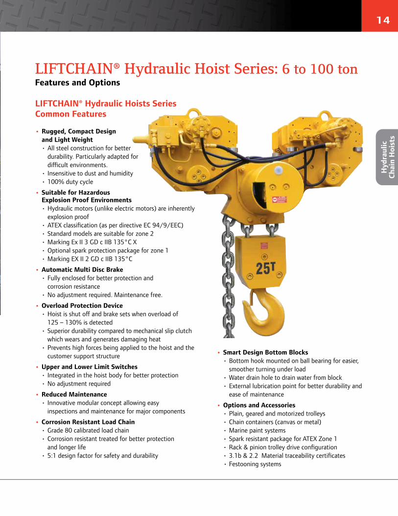
14
LIFTCHAIN® Hydraulic Hoist Series: 6 to 100 tonFeatures and Options
Hyd
raul
ic
Chai
n H
oist
s
• Rugged, Compact Designand Light Weight• All steel construction for better
durability. Particularly adapted fordifficult environments.
• Insensitive to dust and humidity• 100% duty cycle
• Suitable for HazardousExplosion Proof Environments• Hydraulic motors (unlike electric motors) are inherently
explosion proof• ATEX classification (as per directive EC 94/9/EEC)• Standard models are suitable for zone 2• Marking Ex II 3 GD c IIB 135°C X• Optional spark protection package for zone 1• Marking EX II 2 GD c IIB 135°C
• Automatic Multi Disc Brake• Fully enclosed for better protection and
corrosion resistance• No adjustment required. Maintenance free.
• Overload Protection Device• Hoist is shut off and brake sets when overload of
125 – 130% is detected• Superior durability compared to mechanical slip clutch
which wears and generates damaging heat• Prevents high forces being applied to the hoist and the
customer support structure
• Upper and Lower Limit Switches• Integrated in the hoist body for better protection• No adjustment required
• Reduced Maintenance• Innovative modular concept allowing easy
inspections and maintenance for major components
• Corrosion Resistant Load Chain• Grade 80 calibrated load chain• Corrosion resistant treated for better protection
and longer life• 5:1 design factor for safety and durability
• Smart Design Bottom Blocks• Bottom hook mounted on ball bearing for easier,
smoother turning under load• Water drain hole to drain water from block• External lubrication point for better durability and
ease of maintenance
• Options and Accessories• Plain, geared and motorized trolleys• Chain containers (canvas or metal)• Marine paint systems• Spark resistant package for ATEX Zone 1• Rack & pinion trolley drive configuration• 3.1b & 2.2 Material traceability certificates• Festooning systems
LIFTCHAIN® Hydraulic Hoists Series Common Features
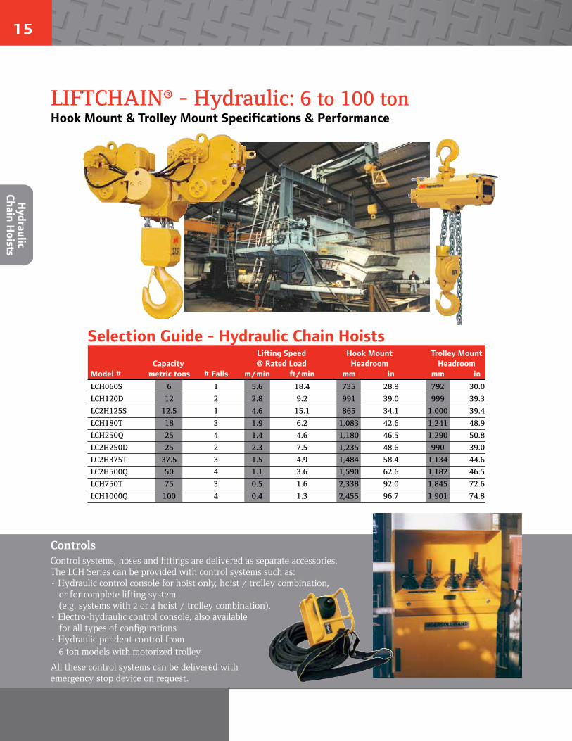
15
LIFTCHAIN® - Hydraulic: 6 to 100 tonHook Mount & Trolley Mount Specifications & Performance
Hydraulic
Chain Hoists
Selection Guide - Hydraulic Chain HoistsLifting Speed Hook Mount Trolley Mount
Capacity @ Rated Load Headroom Headroom Model # metric tons # Falls m/min ft/min mm in mm inLCH060S 6 1 5.6 18.4 735 28.9 792 30.0
LCH120D 12 2 2.8 9.2 991 39.0 999 39.3
LC2H125S 12.5 1 4.6 15.1 865 34.1 1,000 39.4
LCH180T 18 3 1.9 6.2 1,083 42.6 1,241 48.9
LCH250Q 25 4 1.4 4.6 1,180 46.5 1,290 50.8
LC2H250D 25 2 2.3 7.5 1,235 48.6 990 39.0
LC2H375T 37.5 3 1.5 4.9 1,484 58.4 1,134 44.6
LC2H500Q 50 4 1.1 3.6 1,590 62.6 1,182 46.5
LCH750T 75 3 0.5 1.6 2,338 92.0 1,845 72.6
LCH1000Q 100 4 0.4 1.3 2,455 96.7 1,901 74.8
ControlsControl systems, hoses and fittings are delivered as separate accessories. The LCH Series can be provided with control systems such as:• Hydraulic control console for hoist only, hoist / trolley combination,
or for complete lifting system (e.g. systems with 2 or 4 hoist / trolley combination).
• Electro-hydraulic control console, also availablefor all types of configurations
• Hydraulic pendent control from6 ton models with motorized trolley.
All these control systems can be delivered with emergency stop device on request.
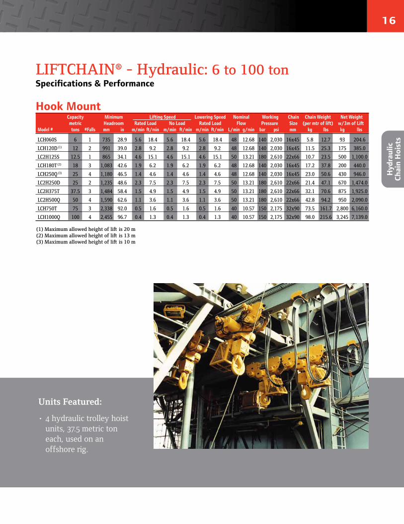
16
Hyd
raul
ic
Chai
n H
oist
s
LIFTCHAIN® - Hydraulic: 6 to 100 tonSpecifications & Performance
Hook MountCapacity Minimum Lifting Speed Lowering Speed Nominal Working Chain Chain Weight Net Weightmetric Headroom Rated Load No Load Rated Load Flow Pressure Size (per mtr of lift) w/3m of Lift
Model # tons #Falls mm in m/min ft/min m/min ft/min m/min ft/min L/min g/min bar psi mm kg lbs kg lbs
LCH060S 6 1 735 28.9 5.6 18.4 5.6 18.4 5.6 18.4 48 12.68 140 2,030 16x45 5.8 12.7 93 204.6
LCH120D (1) 12 2 991 39.0 2.8 9.2 2.8 9.2 2.8 9.2 48 12.68 140 2,030 16x45 11.5 25.3 175 385.0
LC2H125S 12.5 1 865 34.1 4.6 15.1 4.6 15.1 4.6 15.1 50 13.21 180 2,610 22x66 10.7 23.5 500 1,100.0
LCH180T (2) 18 3 1,083 42.6 1.9 6.2 1.9 6.2 1.9 6.2 48 12.68 140 2,030 16x45 17.2 37.8 200 440.0
LCH250Q (3) 25 4 1,180 46.5 1.4 4.6 1.4 4.6 1.4 4.6 48 12.68 140 2,030 16x45 23.0 50.6 430 946.0
LC2H250D 25 2 1,235 48.6 2.3 7.5 2.3 7.5 2.3 7.5 50 13.21 180 2,610 22x66 21.4 47.1 670 1,474.0
LC2H375T 37.5 3 1,484 58.4 1.5 4.9 1.5 4.9 1.5 4.9 50 13.21 180 2,610 22x66 32.1 70.6 875 1,925.0
LC2H500Q 50 4 1,590 62.6 1.1 3.6 1.1 3.6 1.1 3.6 50 13.21 180 2,610 22x66 42.8 94.2 950 2,090.0
LCH750T 75 3 2,338 92.0 0.5 1.6 0.5 1.6 0.5 1.6 40 10.57 150 2,175 32x90 73.5 161.7 2,800 6,160.0
LCH1000Q 100 4 2,455 96.7 0.4 1.3 0.4 1.3 0.4 1.3 40 10.57 150 2,175 32x90 98.0 215.6 3,245 7,139.0
(1) Maximum allowed height of lift is 20 m(2) Maximum allowed height of lift is 13 m(3) Maximum allowed height of lift is 10 m
Units Featured:
• 4 hydraulic trolley hoistunits, 37.5 metric toneach, used on anoffshore rig.
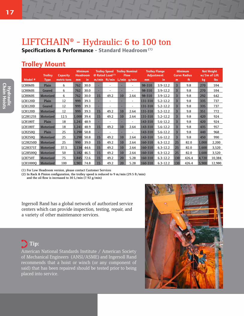
17
LIFTCHAIN® - Hydraulic: 6 to 100 tonSpecifications & Performance - Standard Headroom (1)
Hydraulic
Chain Hoists
Working pressure range = x to y, (1) Hoist and trolley- 3 m of lift and 2 m of control drop. Minimum Trolley Speed Trolley Nominal Trolley Flange Minimum Net WeightTrolley Capacity Headroom @ Rated Load (2) Flow Adjustment Curve Radius w/3m of Lift
Model # Type metric tons mm in m/min ft/min L/min g/min mm in m ft kg lbs
LCH060S Plain 6 762 30.0 - - - - 98-310 3.9-12.2 3 9.8 270 594
LCH060S Geared 6 762 30.0 - - - - 98-310 3.9-12.2 3 9.8 270 594
LCH060S Motorized 6 762 30.0 15 49.2 10 2.64 98-310 3.9-12.2 3 9.8 292 642
LCH120D Plain 12 999 39.3 - - - - 131-310 5.2-12.2 3 9.8 335 737
LCH120D Geared 12 999 39.3 - - - - 131-310 5.2-12.2 3 9.8 335 737
LCH120D Motorized 12 999 39.3 15 49.2 10 2.64 131-310 5.2-12.2 3 9.8 351 772
LC2H125S Motorized 12.5 1,000 39.4 15 49.2 10 2.64 131-310 5.2-12.2 3 9.8 420 924
LCH180T Plain 18 1,241 48.9 - - - - 143-310 5.6-12.2 3 9.8 420 924
LCH180T Motorized 18 1,241 48.9 15 49.2 10 2.64 143-310 5.6-12.2 3 9.8 435 957
LCH250Q Plain 25 1,290 50.8 - - - - 143-310 5.6-12.2 3 9.8 440 968
LCH250Q Motorized 25 1,290 50.8 15 49.2 10 2.64 143-310 5.6-12.2 3 9.8 450 990
LC2H250D Motorized 25 990 39.0 15 49.2 10 2.64 160-310 6.3-12.2 25 82.0 1,000 2,200
LC2H375T Motorized 37.5 1,134 44.6 15 49.2 10 2.64 160-310 6.3-12.2 25 82.0 1,600 3,520
LC2H500Q Motorized 50 1,182 46.5 15 49.2 10 2.64 160-310 6.3-12.2 25 82.0 1,600 3,520
LCH750T Motorized 75 1,845 72.6 15 49.2 20 5.28 160-310 6.3-12.2 130 426.4 4,720 10,384
LCH1000Q Motorized 100 1,901 74.8 15 49.2 20 5.28 160-310 6.3-12.2 130 426.4 5,900 12,980
Trolley Mount
Tip: American National Standards Institute / American Society of Mechanical Engineers (ANSI/ASME) and Ingersoll Rand recommends that a hoist or winch (or any component of said) that has been repaired should be tested prior to being placed into service.
➲
Ingersoll Rand has a global network of authorized service centers which can provide inspection, testing, repair, anda variety of other maintenance services.
(1) For Low Headroom version, please contact Customer Services(2) In Rack & Pinion configuration, the trolley speed is reduced to 9 m/min (29.5 ft/min)
and the oil flow is increased to 30 L/min (7.92 g/min)
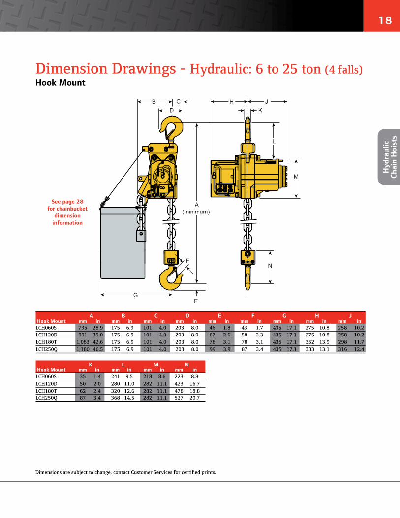
18
B C KD
A(minimum)
M
L
N
G
H J
F
E
Dimension Drawings - Hydraulic: 6 to 25 ton (4 falls)Hook Mount
Hyd
raul
ic
Chai
n H
oist
s
See page 28 for chainbucket
dimension information
A B C D E F G H J Hook Mount mm in mm in mm in mm in mm in mm in mm in mm in mm inLCH060S 735 28.9 175 6.9 101 4.0 203 8.0 46 1.8 43 1.7 435 17.1 275 10.8 258 10.2LCH120D 991 39.0 175 6.9 101 4.0 203 8.0 67 2.6 58 2.3 435 17.1 275 10.8 258 10.2LCH180T 1,083 42.6 175 6.9 101 4.0 203 8.0 78 3.1 78 3.1 435 17.1 352 13.9 298 11.7LCH250Q 1,180 46.5 175 6.9 101 4.0 203 8.0 99 3.9 87 3.4 435 17.1 333 13.1 316 12.4
K L M N Hook Mount mm in mm in mm in mm inLCH060S 35 1.4 241 9.5 218 8.6 223 8.8LCH120D 50 2.0 280 11.0 282 11.1 423 16.7LCH180T 62 2.4 320 12.6 282 11.1 478 18.8LCH250Q 87 3.4 368 14.5 282 11.1 527 20.7
Dimensions are subject to change, contact Customer Services for certified prints.

19
Dimension Drawings - Hydraulic: 12.5 to 100 tonHook Mount
B C
D
G M
F
H
K
L
A
E
J
A B C D E F G H J Hook Mount mm in mm in mm in mm in mm in mm in mm in mm in mm inLC2H125S 865 34.1 446 17.6 265 10.4 222 8.7 58 2.3 273 10.7 475 18.7 57 2.2 391 15.4LC2H250D 1,235 48.6 446 17.6 265 10.4 340 13.4 87 3.4 273 10.7 475 18.7 80 3.1 391 15.4LC2H375T 1,484 58.4 500 19.7 373 14.7 390 15.4 103 4.1 273 10.7 475 18.7 125 4.9 407 16.0LC2H500Q 1,590 62.6 527 20.7 346 13.6 440 17.3 118 4.6 273 10.7 475 18.7 140 5.5 416 16.4LCH750T 2,338 92.0 560 22.0 688 27.1 574 22.6 156 6.1 273 10.7 912 35.9 180 7.1 774 30.5LCH1000Q 2,455 96.7 597 23.5 652 25.7 610 24.0 180 7.1 273 10.7 1,102 43.4 200 7.9 774 30.5
K L M Hook Mount mm in mm in mm inLC2H125S 296 11.7 67 2.6 836 32.9LC2H250D 573 22.6 94 3.7 836 32.9LC2H375T 714 28.1 132 5.2 836 32.9LC2H500Q 763 30.0 150 5.9 836 32.9LCH750T 1,055 41.5 190 7.5 1,165 45.9LCH1000Q 1,111 43.7 250 9.8 1,365 53.7
See page 28 for chainbucket
dimension information
Hydraulic
Chain Hoists
Dimensions are subject to change, contact Customer Services for certified prints.
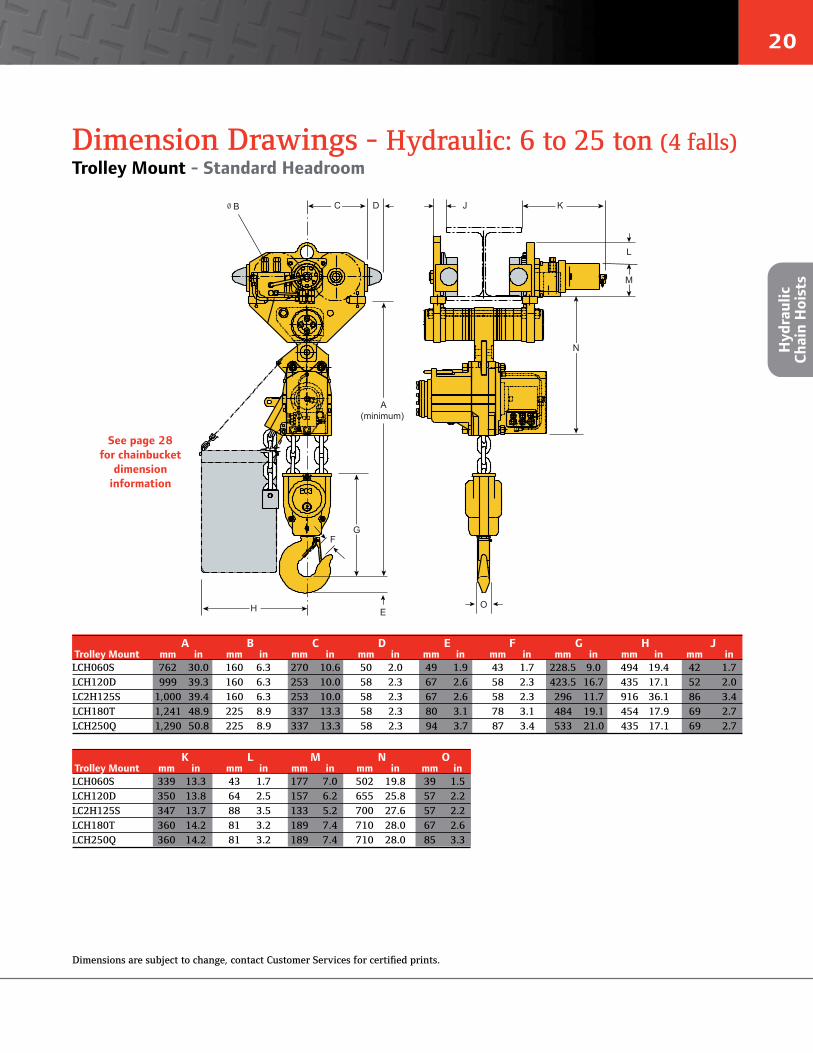
20
Hyd
raul
ic
Chai
n H
oist
s
A(minimum)
E
G
H
F
J KDC
N
M
L
ø B
O
Dimension Drawings - Hydraulic: 6 to 25 ton (4 falls)Trolley Mount - Standard Headroom
K L M N O Trolley Mount mm in mm in mm in mm in mm inLCH060S 339 13.3 43 1.7 177 7.0 502 19.8 39 1.5LCH120D 350 13.8 64 2.5 157 6.2 655 25.8 57 2.2LC2H125S 347 13.7 88 3.5 133 5.2 700 27.6 57 2.2LCH180T 360 14.2 81 3.2 189 7.4 710 28.0 67 2.6LCH250Q 360 14.2 81 3.2 189 7.4 710 28.0 85 3.3
See page 28 for chainbucket
dimension information
A B C D E F G H J Trolley Mount mm in mm in mm in mm in mm in mm in mm in mm in mm inLCH060S 762 30.0 160 6.3 270 10.6 50 2.0 49 1.9 43 1.7 228.5 9.0 494 19.4 42 1.7LCH120D 999 39.3 160 6.3 253 10.0 58 2.3 67 2.6 58 2.3 423.5 16.7 435 17.1 52 2.0LC2H125S 1,000 39.4 160 6.3 253 10.0 58 2.3 67 2.6 58 2.3 296 11.7 916 36.1 86 3.4LCH180T 1,241 48.9 225 8.9 337 13.3 58 2.3 80 3.1 78 3.1 484 19.1 454 17.9 69 2.7LCH250Q 1,290 50.8 225 8.9 337 13.3 58 2.3 94 3.7 87 3.4 533 21.0 435 17.1 69 2.7
Dimensions are subject to change, contact Customer Services for certified prints.

21
Dimension Drawings - Hydraulic: 25 (2 falls) to 100 tonTrolley Mount - Standard Headroom
Hydraulic
Chain Hoists
J
N
M
K
H
P
A
E
ø D
CB
F
O
G
L
A B C D E F G H J Trolley Mount mm in mm in mm in mm in mm in mm in mm in mm in mm inLC2H250D 990 39.0 343 13.5 265 10.4 160 6.3 40 1.6 84 3.3 475 18.7 58 2.3 1,246 49.1LC2H375T 1,134 44.6 372 14.6 373 14.7 225 8.9 40 1.6 125 4.9 475 18.7 58 2.3 1,556 61.3LC2H500Q 1,182 46.5 372 14.6 346 13.6 225 8.9 40 1.6 140 5.5 475 18.7 58 2.3 1,556 61.3LCH750T 1,845 72.6 376 14.8 684 26.9 225 8.9 70 2.8 180 7.1 1,102 43.4 58 2.3 3,254 128.1LCH1000Q 1,901 74.8 376 14.8 652 25.7 225 8.9 70 2.8 200 7.9 1,021 40.2 58 2.3 3,254 128.1
K L M N O P Trolley Mount mm in mm in mm in mm in mm in mm inLC2H250D 220 8.7 411 16.2 572 22.5 94 3.7 87 3.4 836 32.9LC2H375T 270 10.6 416 16.4 714 28.1 132 5.2 103 4.1 836 32.9LC2H500Q 270 10.6 416 16.4 763 30.0 150 5.9 118 4.6 836 32.9LCH750T 270 10.6 790 31.1 1,055 41.5 190 7.5 152 6.0 1,402 55.2LCH1000Q 270 10.6 790 31.1 1,111 43.7 212 8.3 180 7.1 1,366 53.8
See page 28 for chainbucket
dimension information
Dimensions are subject to change, contact Customer Services for certified prints.

22
How To OrderModel identification Codes
How to order standard equipmentSpecify the complete model number as shown. Specify beam size, type and flange width. Note that 0 (zero) is a number, not a letter in model part numbers.Example: LC2A250QIP3RE10M15J12-E
Series LC = LIFTCHAIN®
Series LC2 = LIFTCHAIN®
Series, 2ndgeneration
Power typeA = AirH = Hydraulic
Body type IP = Industrial range, pendent controlIC = Industrial range, pull cordIF = Industrial range,
full flow control (Hydraulic
models only)
Control typeOnly with IC models1 = Pull cordOnly with IP models2 = 1 motor pendent3 = 2 motor pendent (3)
0 = No pendent orno control valve
Height of lift 3M = 3 meter
standardlift
XXM = Specifiedlength inmeters
CE package-E = Compliance
with the European Machinery Directives
Control length0 = no control
hose XX = Specified
length inmeters
Load capacity / falls of chain 015S = 1.5 ton / single fall 030D = 3 ton / two falls 040S = 4 ton / single fall 060S = 6 ton / single fall 060Q = 6 ton / four falls 080D = 8 ton / two falls 120D = 12 ton / two falls 125S = 12.5 ton / single fall 180T = 18 ton / three falls 250D = 25 ton / two falls 250Q = 25 ton / four falls 375T = 37.5 ton / three falls 500Q = 50 ton / four falls 750T = 75 ton / three falls 1000Q = 100 ton / four falls
SuspensionA = Fixed lugC = Swivel top hook
PU (1) = Plain rigid universal trolley (flat or tapered beam / 1.5 to 8 ton) PE (1) = Plain rigid trolley (flat beam / 12 to 25 ton) PN (1) = Plain rigid trolley (tapered beam / 12 to 25 ton) GU (1) = Geared rigid universal trolley (flat or tapered beam / 1.5 to 8 ton) GE (1) = Geared rigid trolley (flat beam / 12 ton only) GN (1) = Geared rigid trolley (tapered beam / 12 ton only) VU (1) (2) = Vane motorized rigid universal trolley (flat or tapered beam /
1.5 to 8 ton) VE (1) (2) = Vane motorized rigid trolley (flat beam / 12 to 50 ton) VN (1) (2) = Vane motorized rigid trolley (tapered beam / 12 to 50 ton)
RU = Gear motorized rigid universal trolley (flat or tapered beam) 6,000 and 8,000 kg
RE = Gear motorized rigid trolley (flat beam) 12 to 100 tonRN = Gear motorized rigid trolley (tapered beam) 12 to 100 ton
LC2 A 250Q IP 3 RE 10M 15 J12 -E
LCA/LC2A and LCH The LIFTCHAIN® air and hydraulic models can be CE marked and fitted as standard with all the safety devices for compliance with the European Machinery Directives 89/392/EEC, 91/368/EEC, 93/44/EEC and 93/68/EEC. In this case, they are delivered with the CE mark and an EC declaration of conformity.
LCA/LC2A and LCH delivered without controlThese models are considered as part machines intended for incorporation into assemblies, therefore they are not CE marked but are deliv-ered with a declaration of incorporation. However they are fitted as standard with safety options to allow their incorporation into systems which have to be in compliance with the CE Directives (89/392/EEC, 91/368/EEC, 93/44/EEC, 93/68/EEC).
How
To
Ord
er
(1) Add “L” for low headroom trolley, e.g. LVU or LRU. (2) Add the letter “R” for rack & pinion configuration (e.g. RER) - on flat beam only. (3) For hydraulic trolley hoists, pendent configuration is joystick-style.
* For protection during shipment and due to the wide range of installation variables the air line accessories are not installed on the units at the factory. All accessories are shipped loose for client installation.
** Option T1 (ATEX Zone 1) includes the following: For the hoist: - Cast iron pendent - Bronze coated bottom hook assy For the trolley: - Solid bronze wheels - Pinion drive in solid bronze or stainless steel - Cast iron pendent
- Bronze coated hand wheel for geared trolley - Brass hand chain guide for geared trolley
Compliance with the European Machinery Directives:
Options A = Standard chain bucket B = Large chain bucket C = Extra large chain bucket
J = Air Line Accessories.* (Air only) Specify J1: Filter,
J2: Lubricator, J3: Regulator or any
numerical combination K = Cast iron pendent
(Air only)L = Low Temperature (-20°C)
Certified (includes 3.1b material traceability certificates)
P = Marine paint 150μ QZ = Offshore paint 290μ
including sandblasting T1 = Spark resistant package
(ATEX zone 1**)

23
Service & AccessoriesService
Inspector and Operator Training
Winch and Hoist Service Made SimpleBy choosing Ingersoll Rand Winch and Hoist equipment you’ve made a critical investment in the performance and life of your op-erations. We recognize this investment and are committed to providing you with a responsive and flexible program for maintaining your equipment and reducing downtime.
Ingersoll Rand can tailor a variety of service options to meet your application’s specific requirements. Please contact us to make an appointment to discuss a customized service plan that best suits your needs.
Installation and Start-Up Assistance
System Inspections
Service &
Accessories
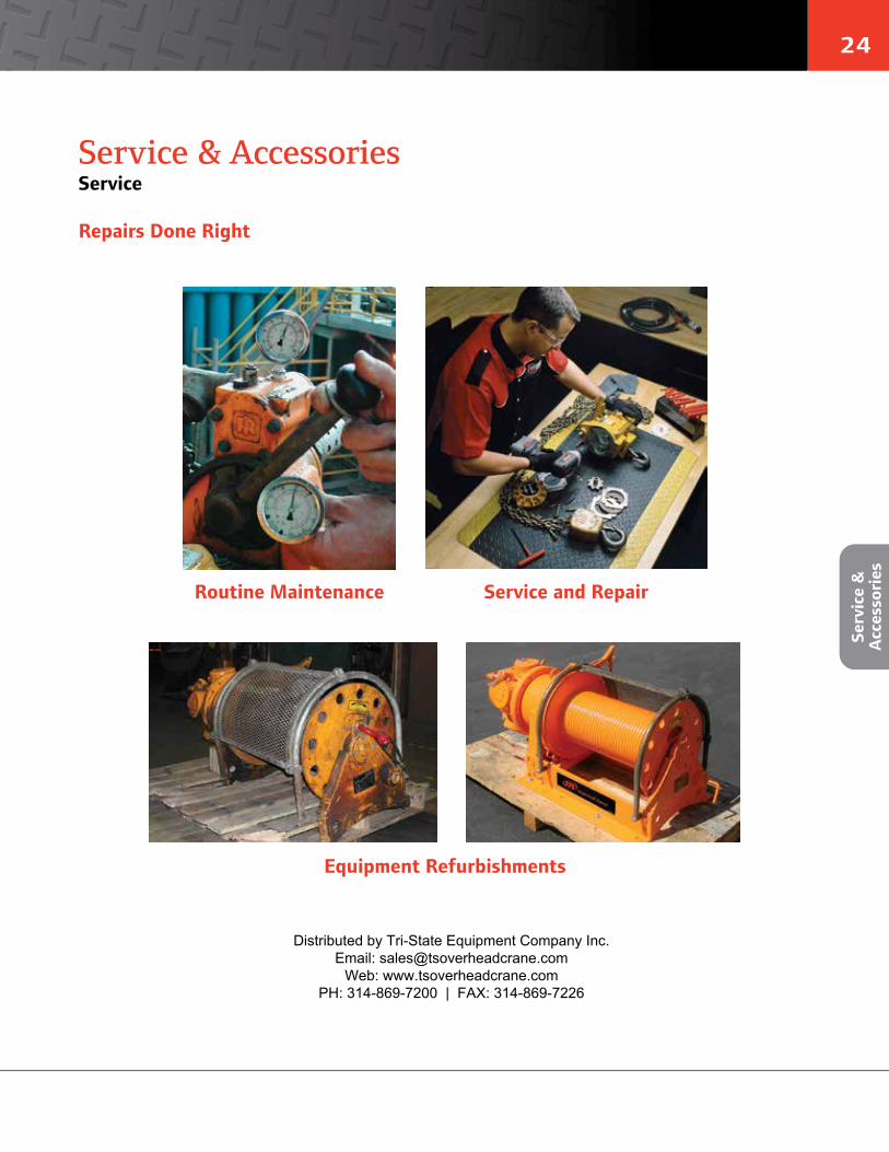
24
Serv
ice
&
Acc
esso
ries
Service & AccessoriesService
Routine Maintenance Service and Repair
Equipment Refurbishments
Repairs Done Right
Distributed by Tri-State Equipment Company Inc.Email: [email protected]
Web: www.tsoverheadcrane.comPH: 314-869-7200 | FAX: 314-869-7226
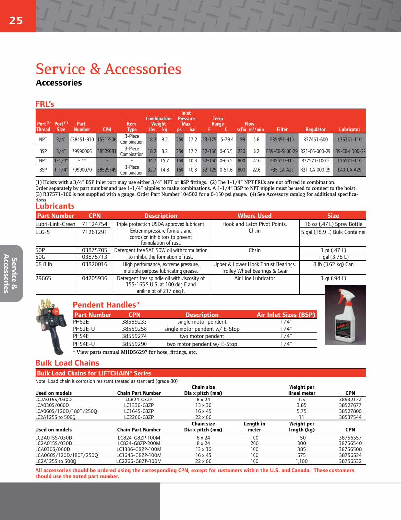
25
Service & AccessoriesAccessories
Service &
Accessories
Part Number CPN Description Air Inlet Sizes (BSP)PHS2E 38559233 single motor pendent 1/4”PHS2E-U 38559258 single motor pendent w/ E-Stop 1/4”PHS4E 38559274 two motor pendent 1/4”PHS4E-U 38559290 two motor pendent w/ E-Stop 1/4”* View parts manual MHD56297 for hose, fittings, etc.
Part Number CPN Description Where Used SizeLubri-Link-Green 71124754 Triple protection USDA approved lubricant. Hook and Latch Pivot Points, 16 oz (.47 L) Spray BottleLLG-5 71261291 Extreme pressure formula and Chain 5 gal (18.9 L) Bulk Container
corrosion inhibitors to prevent formulation of rust.
50P 03875705 Detergent free SAE 50W oil with formulation Chain 1 pt (.47 L) 50G 03875713 to inhibit the formation of rust. 1 gal (3.78 L)68 8 lb 03820016 High performance, extreme pressure, Upper & Lower Hook Thrust Bearings, 8 lb (3.62 kg) Can
multiple purpose lubricating grease. Trolley Wheel Bearings & Gear 29665 04205936 Detergent free spindle oil with viscosity of Air Line Lubricator 1 qt (.94 L)
155-165 S.U.S. at 100 deg F and aniline pt of 217 deg F.
FRL’s
Lubricants
Pendent Handles*
Bulk Load Chains for LIFTCHAIN® SeriesNote: Load chain is corrosion resistant treated as standard (grade 80)
Chain size Weight per Used on models Chain Part Number Dia x pitch (mm) lineal meter CPNLC2A015S/030D LC824-G8ZP 8 x 24 1.5 38532172 LCA030S/060D LC1336-G8ZP 13 x 36 3.85 38527677LCA060S/120D/180T/250Q LC1645-G8ZP 16 x 45 5.75 38527800LC2A125S to 500Q LC2266-G8ZP 22 x 66 11 38537544
Chain size Length in Weight per Used on models Chain Part Number Dia x pitch (mm) meter length (kg) CPN
LC2A015S/030D LC824-G8ZP-100M 8 x 24 100 150 38756557 LC2A015S/030D LC824-G8ZP-200M 8 x 24 200 300 38756540LCA030S/060D LC1336-G8ZP-100M 13 x 36 100 385 38756508LCA060S/120D/180T/250Q LC1645-G8ZP-100M 16 x 45 100 575 38756524LC2A125S to 500Q LC2266-G8ZP-100M 22 x 66 100 1,100 38756532
Bulk Load Chains
(1) Hoists with a 3/4” BSP inlet port may use either 3/4” NPT or BSP fittings. (2) The 1-1/4” NPT FRL’s are not offered in combination. Order separately by part number and use 1-1/4” nipples to make combinations. A 1-1/4” BSP to NPT nipple must be used to connect to the hoist. (3) R37571-100 is not supplied with a gauge. Order Part Number 104502 for a 0-160 psi gauge. (4) See Accessory catalog for additional specifica-tions.
All accessories should be ordered using the corresponding CPN, except for customers within the U.S. and Canada. These customers should use the noted part number.
Inlet Combination Pressure Temp
Port (1) Port (1) Part Item Weight Max Range Flow Thread Size Number CPN Type lbs kg psi bar F C scfm m3/min Filter Regulator Lubricator
NPT 3/4” C38451-810 15317506 3-Piece 18.2 8.2 250 17.2 23-175 -5-79.4 199 5.6 F35451-410 R37451-600 L36351-110 Combination
BSP 3/4” 79990066 38529681 3-Piece 18.2 8.2 250 17.2 32-150 0-65.5 220 6.2 F39-C6-SL00-29 R21-C6-000-29 L39-C6-LD00-29 CombinationNPT 1-1/4” - (2) - - 34.7 15.7 150 10.3 32-150 0-65.5 800 22.6 F35571-410 R37571-100 (3) L36571-110
BSP 1-1/4” 79990070 38529749 3-Piece 32.7 14.8 150 10.3 32-125 0-51.6 800 22.6 F35-CA-A29 R31-CA-000-29 L40-CA-A29 Combination
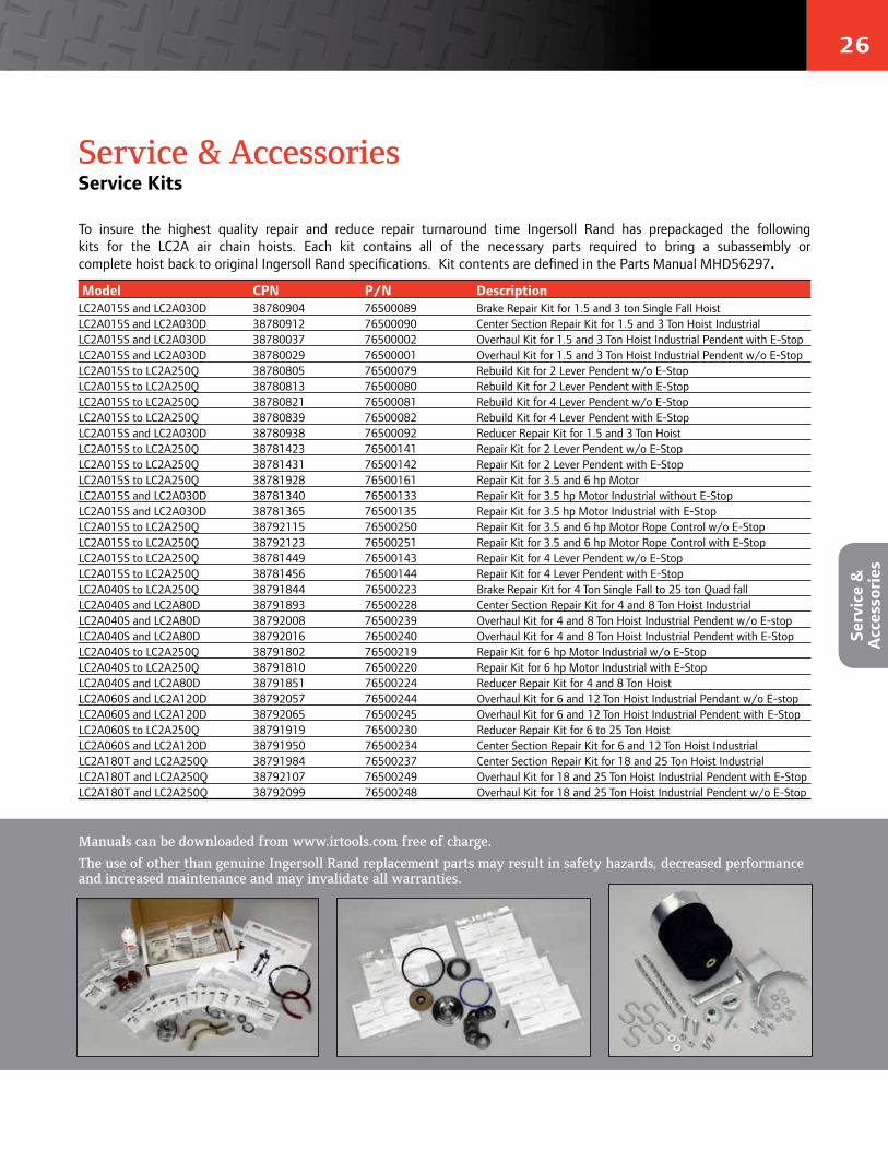
26
Model CPN P/N Description LC2A015S and LC2A030D 38780904 76500089 Brake Repair Kit for 1.5 and 3 ton Single Fall HoistLC2A015S and LC2A030D 38780912 76500090 Center Section Repair Kit for 1.5 and 3 Ton Hoist IndustrialLC2A015S and LC2A030D 38780037 76500002 Overhaul Kit for 1.5 and 3 Ton Hoist Industrial Pendent with E-Stop LC2A015S and LC2A030D 38780029 76500001 Overhaul Kit for 1.5 and 3 Ton Hoist Industrial Pendent w/o E-StopLC2A015S to LC2A250Q 38780805 76500079 Rebuild Kit for 2 Lever Pendent w/o E-StopLC2A015S to LC2A250Q 38780813 76500080 Rebuild Kit for 2 Lever Pendent with E-StopLC2A015S to LC2A250Q 38780821 76500081 Rebuild Kit for 4 Lever Pendent w/o E-StopLC2A015S to LC2A250Q 38780839 76500082 Rebuild Kit for 4 Lever Pendent with E-StopLC2A015S and LC2A030D 38780938 76500092 Reducer Repair Kit for 1.5 and 3 Ton HoistLC2A015S to LC2A250Q 38781423 76500141 Repair Kit for 2 Lever Pendent w/o E-StopLC2A015S to LC2A250Q 38781431 76500142 Repair Kit for 2 Lever Pendent with E-StopLC2A015S to LC2A250Q 38781928 76500161 Repair Kit for 3.5 and 6 hp MotorLC2A015S and LC2A030D 38781340 76500133 Repair Kit for 3.5 hp Motor Industrial without E-StopLC2A015S and LC2A030D 38781365 76500135 Repair Kit for 3.5 hp Motor Industrial with E-StopLC2A015S to LC2A250Q 38792115 76500250 Repair Kit for 3.5 and 6 hp Motor Rope Control w/o E-StopLC2A015S to LC2A250Q 38792123 76500251 Repair Kit for 3.5 and 6 hp Motor Rope Control with E-StopLC2A015S to LC2A250Q 38781449 76500143 Repair Kit for 4 Lever Pendent w/o E-StopLC2A015S to LC2A250Q 38781456 76500144 Repair Kit for 4 Lever Pendent with E-StopLC2A040S to LC2A250Q 38791844 76500223 Brake Repair Kit for 4 Ton Single Fall to 25 ton Quad fallLC2A040S and LC2A80D 38791893 76500228 Center Section Repair Kit for 4 and 8 Ton Hoist IndustrialLC2A040S and LC2A80D 38792008 76500239 Overhaul Kit for 4 and 8 Ton Hoist Industrial Pendent w/o E-stop LC2A040S and LC2A80D 38792016 76500240 Overhaul Kit for 4 and 8 Ton Hoist Industrial Pendent with E-StopLC2A040S to LC2A250Q 38791802 76500219 Repair Kit for 6 hp Motor Industrial w/o E-StopLC2A040S to LC2A250Q 38791810 76500220 Repair Kit for 6 hp Motor Industrial with E-StopLC2A040S and LC2A80D 38791851 76500224 Reducer Repair Kit for 4 and 8 Ton HoistLC2A060S and LC2A120D 38792057 76500244 Overhaul Kit for 6 and 12 Ton Hoist Industrial Pendant w/o E-stopLC2A060S and LC2A120D 38792065 76500245 Overhaul Kit for 6 and 12 Ton Hoist Industrial Pendent with E-Stop LC2A060S to LC2A250Q 38791919 76500230 Reducer Repair Kit for 6 to 25 Ton HoistLC2A060S and LC2A120D 38791950 76500234 Center Section Repair Kit for 6 and 12 Ton Hoist IndustrialLC2A180T and LC2A250Q 38791984 76500237 Center Section Repair Kit for 18 and 25 Ton Hoist IndustrialLC2A180T and LC2A250Q 38792107 76500249 Overhaul Kit for 18 and 25 Ton Hoist Industrial Pendent with E-Stop LC2A180T and LC2A250Q 38792099 76500248 Overhaul Kit for 18 and 25 Ton Hoist Industrial Pendent w/o E-Stop
Service & AccessoriesService Kits
To insure the highest quality repair and reduce repair turnaround time Ingersoll Rand has prepackaged the following kits for the LC2A air chain hoists. Each kit contains all of the necessary parts required to bring a subassembly or complete hoist back to original Ingersoll Rand specifications. Kit contents are defined in the Parts Manual MHD56297.
Manuals can be downloaded from www.irtools.com free of charge.
The use of other than genuine Ingersoll Rand replacement parts may result in safety hazards, decreased performance and increased maintenance and may invalidate all warranties.
Serv
ice
&
Acc
esso
ries
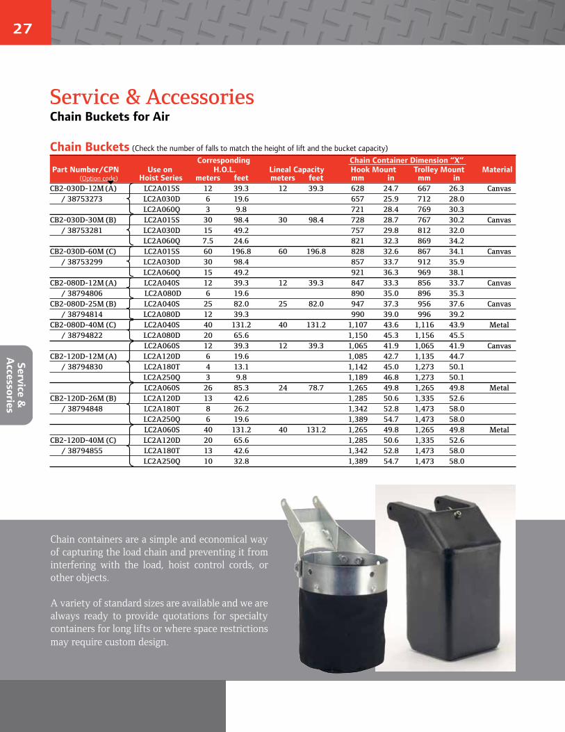
27
Service &
Accessories
Service & AccessoriesChain Buckets for Air
Chain Buckets (Check the number of falls to match the height of lift and the bucket capacity)Corresponding Chain Container Dimension “X”
Part Number/CPN Use on H.O.L. Lineal Capacity Hook Mount Trolley Mount Material (Option code) Hoist Series meters feet meters feet mm in mm in
CB2-030D-12M (A) LC2A015S 12 39.3 12 39.3 628 24.7 667 26.3 Canvas / 38753273 LC2A030D 6 19.6 657 25.9 712 28.0
LC2A060Q 3 9.8 721 28.4 769 30.3CB2-030D-30M (B) LC2A015S 30 98.4 30 98.4 728 28.7 767 30.2 Canvas / 38753281 LC2A030D 15 49.2 757 29.8 812 32.0
LC2A060Q 7.5 24.6 821 32.3 869 34.2CB2-030D-60M (C) LC2A015S 60 196.8 60 196.8 828 32.6 867 34.1 Canvas / 38753299 LC2A030D 30 98.4 857 33.7 912 35.9
LC2A060Q 15 49.2 921 36.3 969 38.1CB2-080D-12M (A) LC2A040S 12 39.3 12 39.3 847 33.3 856 33.7 Canvas
/ 38794806 LC2A080D 6 19.6 890 35.0 896 35.3CB2-080D-25M (B) LC2A040S 25 82.0 25 82.0 947 37.3 956 37.6 Canvas / 38794814 LC2A080D 12 39.3 990 39.0 996 39.2CB2-080D-40M (C) LC2A040S 40 131.2 40 131.2 1,107 43.6 1,116 43.9 Metal / 38794822 LC2A080D 20 65.6 1,150 45.3 1,156 45.5
LC2A060S 12 39.3 12 39.3 1,065 41.9 1,065 41.9 CanvasCB2-120D-12M (A) LC2A120D 6 19.6 1,085 42.7 1,135 44.7 / 38794830 LC2A180T 4 13.1 1,142 45.0 1,273 50.1
LC2A250Q 3 9.8 1,189 46.8 1,273 50.1LC2A060S 26 85.3 24 78.7 1,265 49.8 1,265 49.8 Metal
CB2-120D-26M (B) LC2A120D 13 42.6 1,285 50.6 1,335 52.6 / 38794848 LC2A180T 8 26.2 1,342 52.8 1,473 58.0
LC2A250Q 6 19.6 1,389 54.7 1,473 58.0LC2A060S 40 131.2 40 131.2 1,265 49.8 1,265 49.8 Metal
CB2-120D-40M (C) LC2A120D 20 65.6 1,285 50.6 1,335 52.6 / 38794855 LC2A180T 13 42.6 1,342 52.8 1,473 58.0
LC2A250Q 10 32.8 1,389 54.7 1,473 58.0
Chain containers are a simple and economical way of capturing the load chain and preventing it from interfering with the load, hoist control cords, or other objects.
A variety of standard sizes are available and we are always ready to provide quotations for specialty containers for long lifts or where space restrictions may require custom design.
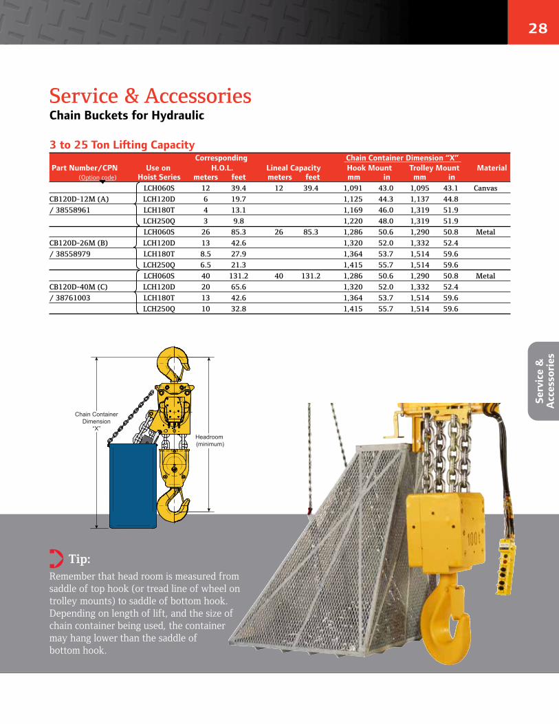
28
Service & AccessoriesChain Buckets for Hydraulic
Serv
ice
&
Acc
esso
ries
3 to 25 Ton Lifting CapacityCorresponding Chain Container Dimension “X”
Part Number/CPN Use on H.O.L. Lineal Capacity Hook Mount Trolley Mount Material (Option code) Hoist Series meters feet meters feet mm in mm in
LCH060S 12 39.4 12 39.4 1,091 43.0 1,095 43.1 Canvas
CB120D-12M (A) LCH120D 6 19.7 1,125 44.3 1,137 44.8
/ 38558961 LCH180T 4 13.1 1,169 46.0 1,319 51.9
LCH250Q 3 9.8 1,220 48.0 1,319 51.9
LCH060S 26 85.3 26 85.3 1,286 50.6 1,290 50.8 Metal
CB120D-26M (B) LCH120D 13 42.6 1,320 52.0 1,332 52.4
/ 38558979 LCH180T 8.5 27.9 1,364 53.7 1,514 59.6
LCH250Q 6.5 21.3 1,415 55.7 1,514 59.6
LCH060S 40 131.2 40 131.2 1,286 50.6 1,290 50.8 Metal
CB120D-40M (C) LCH120D 20 65.6 1,320 52.0 1,332 52.4
/ 38761003 LCH180T 13 42.6 1,364 53.7 1,514 59.6
LCH250Q 10 32.8 1,415 55.7 1,514 59.6
Tip: Remember that head room is measured from saddle of top hook (or tread line of wheel on trolley mounts) to saddle of bottom hook. Depending on length of lift, and the size of chain container being used, the container may hang lower than the saddle of bottom hook.
Headroom (minimum)
Chain ContainerDimension
“X”
➲
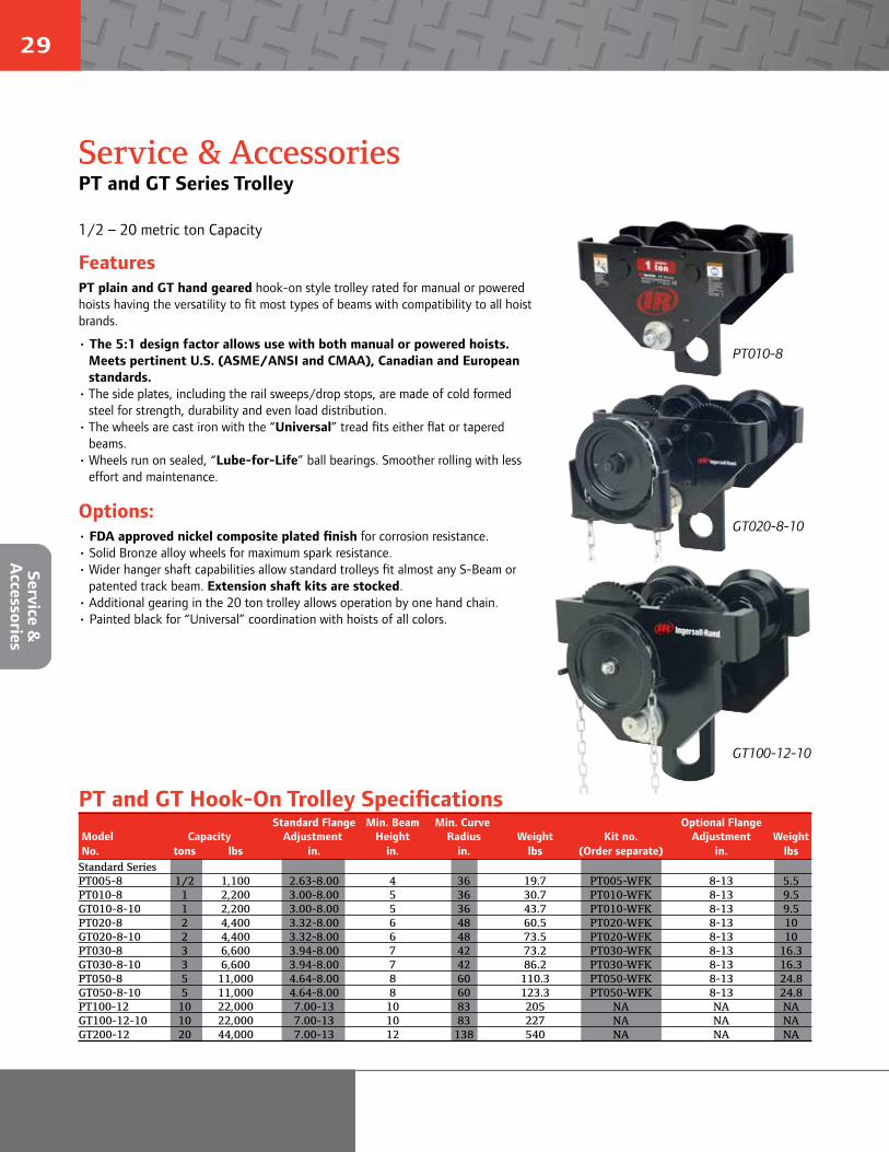
29
Service & AccessoriesPT and GT Series Trolley
FeaturesPT plain and GT hand geared hook-on style trolley rated for manual or powered hoists having the versatility to fit most types of beams with compatibility to all hoist brands.
• The 5:1 design factor allows use with both manual or powered hoists.Meets pertinent U.S. (ASME/ANSI and CMAA), Canadian and Europeanstandards.
• The side plates, including the rail sweeps/drop stops, are made of cold formedsteel for strength, durability and even load distribution.
• The wheels are cast iron with the “Universal” tread fits either flat or taperedbeams.
• Wheels run on sealed, “Lube-for-Life” ball bearings. Smoother rolling with lesseffort and maintenance.
Options:• FDA approved nickel composite plated finish for corrosion resistance.• Solid Bronze alloy wheels for maximum spark resistance.• Wider hanger shaft capabilities allow standard trolleys fit almost any S-Beam or
patented track beam. Extension shaft kits are stocked.• Additional gearing in the 20 ton trolley allows operation by one hand chain.• Painted black for “Universal” coordination with hoists of all colors.
Standard Flange Min. Beam Min. Curve Optional Flange Model Capacity Adjustment Height Radius Weight Kit no. Adjustment Weight No. tons lbs in. in. in. lbs (Order separate) in. lbsStandard SeriesPT005-8 1/2 1,100 2.63-8.00 4 36 19.7 PT005-WFK 8-13 5.5PT010-8 1 2,200 3.00-8.00 5 36 30.7 PT010-WFK 8-13 9.5GT010-8-10 1 2,200 3.00-8.00 5 36 43.7 PT010-WFK 8-13 9.5PT020-8 2 4,400 3.32-8.00 6 48 60.5 PT020-WFK 8-13 10GT020-8-10 2 4,400 3.32-8.00 6 48 73.5 PT020-WFK 8-13 10PT030-8 3 6,600 3.94-8.00 7 42 73.2 PT030-WFK 8-13 16.3GT030-8-10 3 6,600 3.94-8.00 7 42 86.2 PT030-WFK 8-13 16.3PT050-8 5 11,000 4.64-8.00 8 60 110.3 PT050-WFK 8-13 24.8GT050-8-10 5 11,000 4.64-8.00 8 60 123.3 PT050-WFK 8-13 24.8PT100-12 10 22,000 7.00-13 10 83 205 NA NA NAGT100-12-10 10 22,000 7.00-13 10 83 227 NA NA NAGT200-12 20 44,000 7.00-13 12 138 540 NA NA NA
PT and GT Hook-On Trolley Specifications
PT010-8
GT020-8-10
GT100-12-10
1/2 – 20 metric ton Capacity
Service &
Accessories
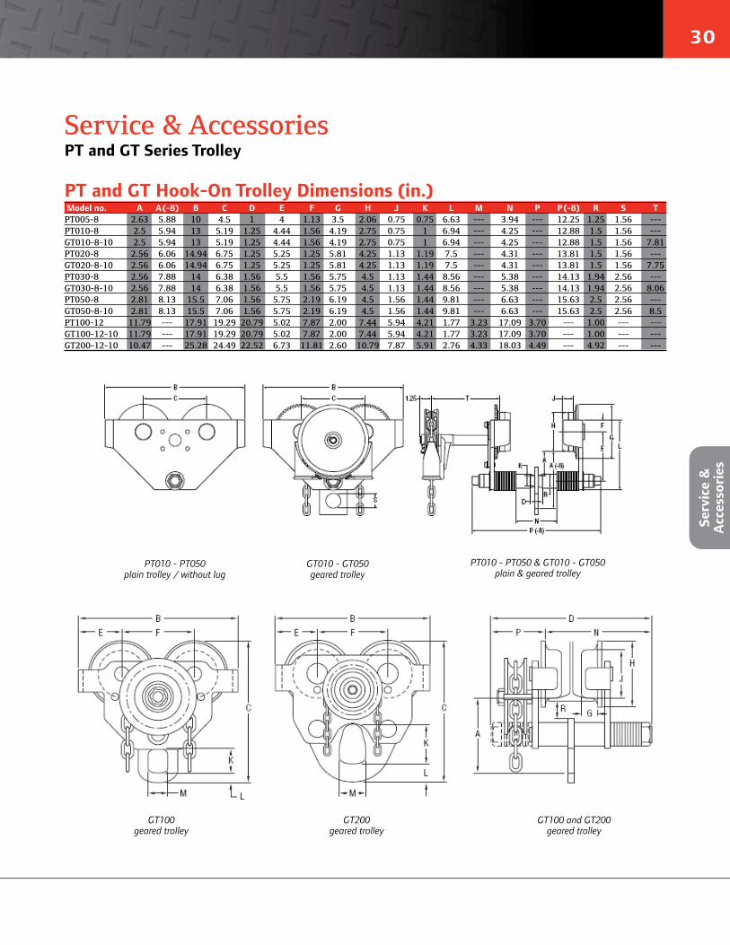
30
Service & AccessoriesPT and GT Series Trolley
Model no. A A (-8) B C D E F G H J K L M N P P (-8) R S TPT005-8 2.63 5.88 10 4.5 1 4 1.13 3.5 2.06 0.75 0.75 6.63 --- 3.94 --- 12.25 1.25 1.56 ---PT010-8 2.5 5.94 13 5.19 1.25 4.44 1.56 4.19 2.75 0.75 1 6.94 --- 4.25 --- 12.88 1.5 1.56 ---GT010-8-10 2.5 5.94 13 5.19 1.25 4.44 1.56 4.19 2.75 0.75 1 6.94 --- 4.25 --- 12.88 1.5 1.56 7.81PT020-8 2.56 6.06 14.94 6.75 1.25 5.25 1.25 5.81 4.25 1.13 1.19 7.5 --- 4.31 --- 13.81 1.5 1.56 ---GT020-8-10 2.56 6.06 14.94 6.75 1.25 5.25 1.25 5.81 4.25 1.13 1.19 7.5 --- 4.31 --- 13.81 1.5 1.56 7.75PT030-8 2.56 7.88 14 6.38 1.56 5.5 1.56 5.75 4.5 1.13 1.44 8.56 --- 5.38 --- 14.13 1.94 2.56 ---GT030-8-10 2.56 7.88 14 6.38 1.56 5.5 1.56 5.75 4.5 1.13 1.44 8.56 --- 5.38 --- 14.13 1.94 2.56 8.06PT050-8 2.81 8.13 15.5 7.06 1.56 5.75 2.19 6.19 4.5 1.56 1.44 9.81 --- 6.63 --- 15.63 2.5 2.56 ---GT050-8-10 2.81 8.13 15.5 7.06 1.56 5.75 2.19 6.19 4.5 1.56 1.44 9.81 --- 6.63 --- 15.63 2.5 2.56 8.5PT100-12 11.79 --- 17.91 19.29 20.79 5.02 7.87 2.00 7.44 5.94 4.21 1.77 3.23 17.09 3.70 --- 1.00 --- ---GT100-12-10 11.79 --- 17.91 19.29 20.79 5.02 7.87 2.00 7.44 5.94 4.21 1.77 3.23 17.09 3.70 --- 1.00 --- ---GT200-12-10 10.47 --- 25.28 24.49 22.52 6.73 11.81 2.60 10.79 7.87 5.91 2.76 4.33 18.03 4.49 --- 4.92 --- ---
PT and GT Hook-On Trolley Dimensions (in.)
PT010 - PT050plain trolley / without lug
GT010 - GT050geared trolley
PT010 - PT050 & GT010 - GT050plain & geared trolley
GT100geared trolley
GT200geared trolley
GT100 and GT200geared trolley
Serv
ice
&
Acc
esso
ries
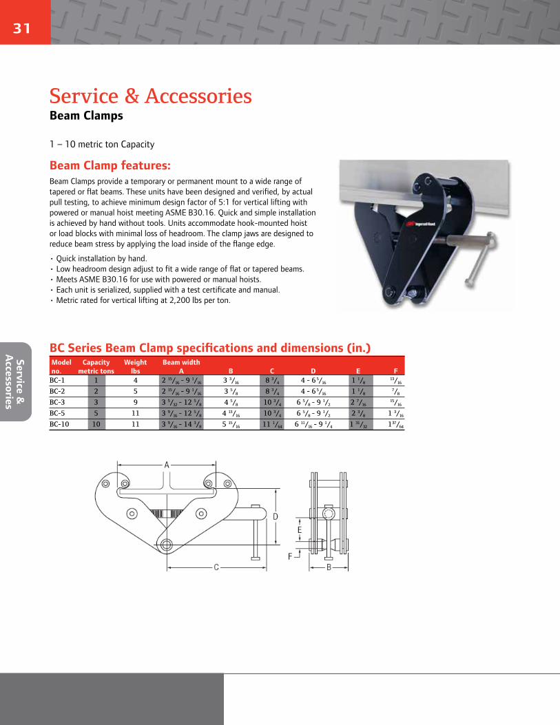
31
Beam Clamp features:Beam Clamps provide a temporary or permanent mount to a wide range of tapered or flat beams. These units have been designed and verified, by actual pull testing, to achieve minimum design factor of 5:1 for vertical lifting with powered or manual hoist meeting ASME B30.16. Quick and simple installation is achieved by hand without tools. Units accommodate hook-mounted hoist or load blocks with minimal loss of headroom. The clamp jaws are designed to reduce beam stress by applying the load inside of the flange edge.
• Quick installation by hand.• Low headroom design adjust to fit a wide range of flat or tapered beams.• Meets ASME B30.16 for use with powered or manual hoists.• Each unit is serialized, supplied with a test certificate and manual.• Metric rated for vertical lifting at 2,200 lbs per ton.
1 – 10 metric ton Capacity
Model Capacity Weight Beam width no. metric tons lbs A B C D E FBC-1 1 4 2 15/16
- 9 1/16 3 3/16 8 3/4 4 - 6 5/16 1 1/8 13/16
BC-2 2 5 2 15/16 - 9 1/16 3 5/8 8 3/4 4 - 6 5/16 1 1/8 7/8
BC-3 3 9 3 5/32 - 12 5/8 4 5/8 10 3/4 6 5/8 - 9 1/2 2 7/16 15/16
BC-5 5 11 3 9/16 - 12 5/8 4 13/16 10 3/4 6 5/8 - 9 1/2 2 3/8 1 3/16
BC-10 10 11 3 9/16 - 14 3/8 5 15/16 11 1/64 6 11/16 - 9 1/4 1 31/32 137/64
BC Series Beam Clamp specifications and dimensions (in.)
Service & AccessoriesBeam Clamps
Service &
Accessories

32
Solu
tion
s
SolutionsSpecial Orders
A significant portion of our business is providing customized solutions for specific applications. We recognize that not all jobs are created equal and that the most cost-effective solutions may not be in an off-the-shelf item. We’ve designed and manufactured winches and hoists for applications as simple as moving bags of lettuce, to as intricate as installing critical payloads on space vehicles.
Clean Room Hoists
Custom Levelwinds
Electric Man Rider™ Winches
Electric Chain Hoists For Explosion Proof Environments Waterfall Winch Systems
ASME NUM1 Critical Load Handling Hoists
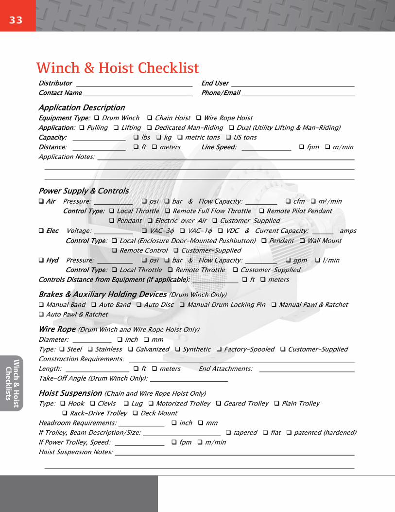
33
Winch & Hoist Checklist
Winch &
Hoist
Checklists
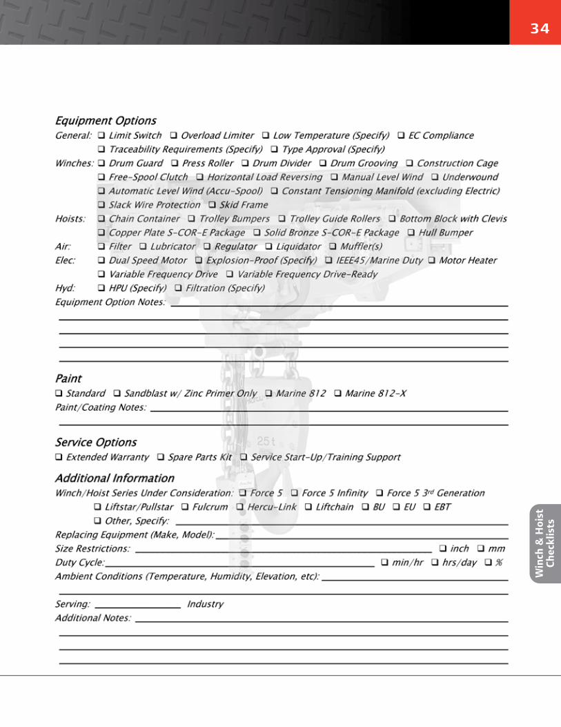
34
Win
ch &
Hoi
st
Chec
klis
ts

© 2014 Ingersoll Rand IRITS-0409-051 Back Cover Revision / 02212014
Ingersoll Rand (NYSE:IR) advances the quality of life by creating and sustaining safe, comfortable and efficient environments. Our people and our family of brands—including Club Car®, Ingersoll Rand®, Thermo King® and Trane® —work together to enhance the quality and comfort of air in homes and buildings; transport and protect food and perishables; secure homes and commercial properties; and increase industrial productivity and efficiency. Ingersoll Rand products range from complete compressed air systems, tools and pumps to material handling systems. The diverse and innovative products, services and solutions enhance our customers’ energy efficiency, productivity and operations. We are a $14 billion global business committed to a world of sustainable progress and enduring results. For more information, visit ingersollrand.com.
Ingersoll Rand, IR and the IR logo are trademarks of Ingersoll Rand, its subsidiaries and/or affiliates. All other trademarks are the property of their respective owners.
WARNING: This equipment is not designed for transporting people or lifting loads above people. It is the user’s responsibility to determine the suitability of this product for any particular use and to check compliance with applicable regulations. Before installation, see maintenance and operations manual for additional warnings and precautions
Nothing contained on these pages is intended to extend any warranty or representation, expressed or implied, regarding the product described herein. Any such warranties or other terms and conditions of sale of products shall be in accordance with Ingersoll Rand’s standard terms and conditions of sale for such products, which are available upon request.
Product improvement is a continuing goal at Ingersoll Rand. Designs and specifications are subject to change without notice or obligation.
Distributed by Tri-State Equipment Company Inc.Email: [email protected]
Web: www.tsoverheadcrane.comPH: 314-869-7200 | FAX: 314-869-7226