borehole geology and hydrothermal alteration of … · orkustofnun, grensasvegur 9, reports 2015...
TRANSCRIPT
Orkustofnun, Grensasvegur 9, Reports 2015 IS-108 Reykjavik, Iceland Number 15
277
BOREHOLE GEOLOGY AND HYDROTHERMAL ALTERATION OF WELL HE-58, HELLISHEIDI GEOTHERMAL FIELD, SW-ICELAND
Hamda Hassan Wais Ministry of Energy in charge of Natural Resources
Cite Ministerielle, P.O. Box 10010, Djibouti REPUBLIC OF DJIBOUTI [email protected]
ABSTRACT
Well HE-58 is located in the Hellisheidi high temperature field within the Hengill geothermal area in SW-Iceland. This directional well was drilled to a total depth of 2531 m. An analysis of the uppermost 1200 m is presented in this report. Binocular microscope, petrographic microscope, XRD-analysis, a fluid inclusion analysis and geophysical logs were used to gather data which are published and interpreted in the paper. Following binocular and petrographic analyses, it can be concluded that the lithology of well HE-58 mostly comprises hyaloclastite units. The rock types within these hyaloclastite units are: pillow basalts, basaltic breccia, and basaltic tuff. There are also basaltic intrusions at depths of 1050-1060 m and 1142-1148 m. Four feeder zones were identified using temperature, neutron and caliper logs. These zones show an association with circulation losses and lithological boundaries in the upper levels but occur in relation to a basaltic intrusion at depth. Four alteration zones were identified in this well: a zone of no alteration at 0-100 m depth; a zeolite-smectite zone (<200°C) from 200 to 450 m; a chlorite zone (230-250°C) from 450 to 760 m and a chlorite-epidote zone (250-280°C) from 760 to 1200 m. Fluid inclusion studies show a wide range of homogenization temperature which range from 220-386.7°C. The homogenization temperature appears to be in equilibrium with the alteration mineralogy. However, it was not possible to compare the alteration with the formation temperature, because the well was still heating up at the time of the study.
1. INTRODUCTION 1.1 Purpose of the study
The purpose of this study report is to explore the subsurface geology of a geothermal field using data obtained by drilling. Drill cuttings, rig data and geophysical logs were used to study the lithology,

Hamda Hassan Wais 278 Report 15
hydrothermal alteration, and the location of aquifers. Well HE-58 in the Hellisheidi geothermal field was chosen to serve these objectives, but this well is the latest make up well for the Hellisheidi power plant. The main objective of this study is to evaluate the geothermal conditions in the system based on the lithology, hydrothermal mineralization, deposition of alteration minerals in veins and vesicles, and finally the location of aquifers to evaluate permeability and the success of the well. This geological study is mainly based on data available during drilling. 1.2 Geology of Iceland Iceland is geologically a young country. It lies astride one of Earth’s major diverging fault lines, the Mid-Atlantic ridge. This is the boundary between the North American and Eurasian tectonic plates. The two plates are moving apart at a rate of about 2 cm per year (Saemundsson, 1979). Iceland is an anomalous part of the ridge where deep mantle material wells up and creates a hot spot of unusually excessive volcanic productivity. This makes Iceland one of the few places on Earth where one can see an active spreading ridge above sea level. As a result of its location, Iceland is one of the most tectonically active places on Earth, resulting in a large number of volcanoes and hot springs. The volcanic succession of Iceland can be divided into four zones based on the age of the rocks (Figure 1): the upper Tertiary flood basalt formation which is older than 3,1 M.y., the Upper Pliocene and Lower Pleistocene (grey basalt) formation, which are between 0.7 and 3.1 M.y., the Upper Pleistocene (hyaloclastite) formation which is younger, and Postglacial lavas which formed during the last 13.000 years (Saemundsson,1979).
The Iceland Geothermal systems (Figure 1) are divided into two groups, high temperature fields (volcanic geothermal systems) and low-temperature fields (non-volcanic systems). The high temperature fields are located in the active zone of volcanism and rifting and temperatures exceed 200°C at 1000 m depth. The low-temperature fields are widely distributed in Quaternary and Tertiary formations and have lower temperatures (150°C at 1000 m depth) (Fridleifsson, 1979).
FIGURE 1: Geological map of Iceland (Jóhannesson and Saemundsson, 1999)

Report 15 279 Hamda Hassan Wais
1.3 Hengill high-temperature geothermal area The high temperature geothermal area associated with the Hengill central volcano is located in the volcanic rift zone in SW Iceland, approximately 40 km east of Reykjavik. It is located on a triple junction between the southern part of the Western Volcanic Zone, the eastern part of the Reykjanes Peninsula and the South Iceland Seismic Zone and is composed of a complex of fissure swarms and volcanoes (Figure 1). Three fields have been developed within the greater Hengill area: 1) Nesjavellir where a 120 MW power plant is currently in operation, 2) Hellisheidi where a 303 MW power plant is currently in operation, and 3) Hveragerdi, where the geothermal resource is utilized directly by the local community (Björnsson et al., 2003; Franzson et al., 2005). Hellisheidi is one of the geothermal areas within the Hengill system, located in the southern part. The Hellisheidi power plant, situated in the south western part of the Hengill area, was commissioned in 2006. The production capacity of the plant is 303 MWe using a water-steam mixture from 34 wells in the area (Gunnarsson, 2011). 1.3.1 Geology and tectonics of the Hengill area Hengill central volcano (Figure 2) is mainly built up of sub-glacial hyaloclastite formations. Interglacial subaerial lavas erupting within the volcano flowed down the flanks of the volcano and accumulated in
FIGURE 2: Location map of the Hengill volcanic complex (from Pendon, 2006)

Hamda Hassan Wais 280 Report 15
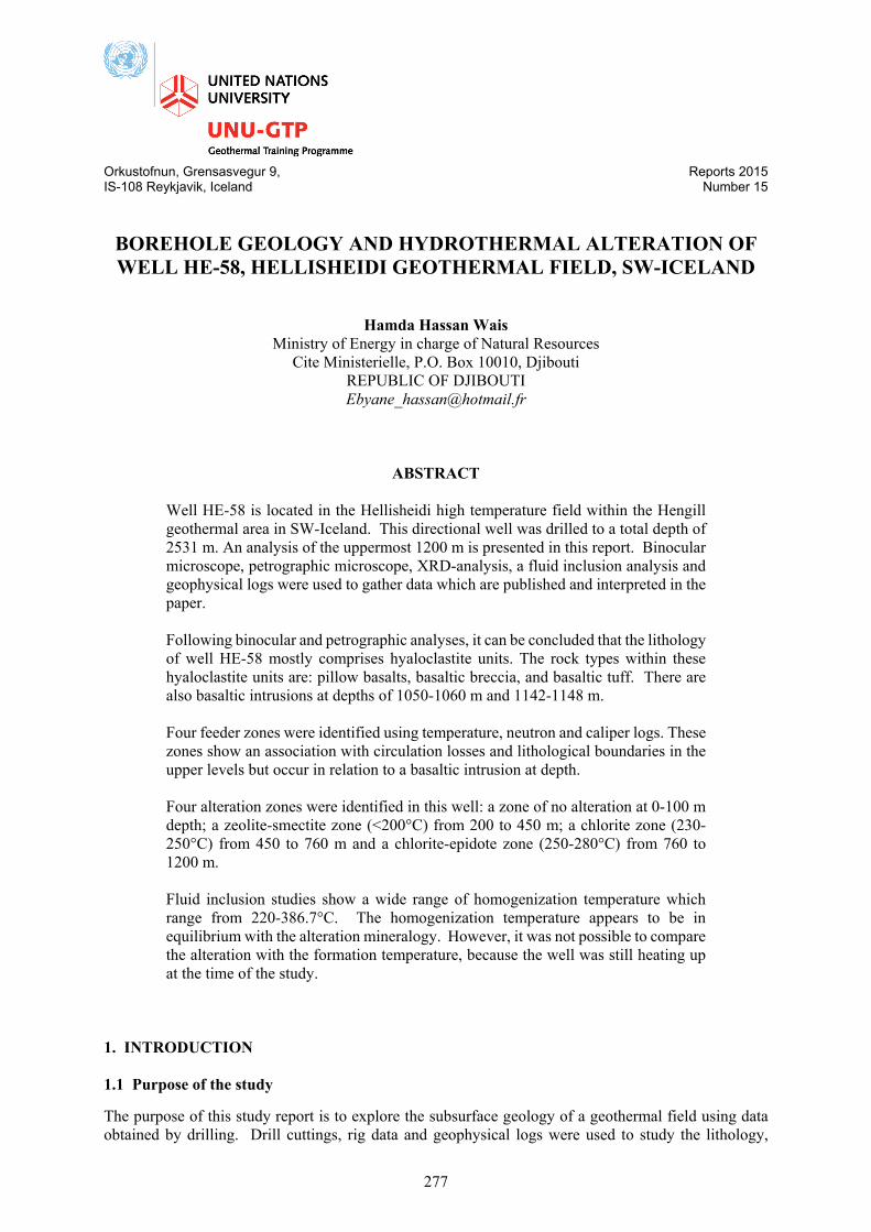
the surrounding lowlands. The age of the volcano has been assessed at around 400,000 years (Franzson et al., 2005). The Hengill volcanic area is commonly divided into three volcanic systems; the youngest and most active one is Mt. Hengill system itself, located in the west of the area within the axial rift zone. The second youngest is the Hrómundartindur system, further to the east, which is much smaller in distribution. The third one, the Hveragerdi system, furthest to the east (Figure 2), is now extinct and was considerably eroded in Pleistocene time. The oldest rocks, about 0.8 my old from the Matuyama epoch, are located in the lowlands southeast of the town of Hveragerdi, and the youngest are the Holocene lava flows from the fissure swarm cutting the Hengill volcano in the west. The Hrómundartindur system also includes an early Holocene lava flow from the Tjarnarhnúkur volcanic cone, extending into western Ölkelduháls (Saemundsson, 1967). An age of about 0.4 million years is proposed for the Hengill central volcano which puts a lower age limit on the geothermal system (Franzson et al., 2005). Tectonically, Hengill is the easternmost of a series of four closely spaced basaltic fissure systems that cut diagonally across the Reykjanes Peninsula. It is traversed by a graben about 10 km broad which runs NE-SW parallel to the hyaloclastite ridges. This graben is part of a greater structure which accompanies the Reykjanes-Langjökull volcanic zone. The western part of the Hengill area is split up by numerous sub parallel normal faults. These constitute a 5 km broad inner graben of intense faulting and fissure volcanism. During Postglacial time, six fissure eruptions occurred within this graben, four south of and two north of the mountain (Franzson et al., 2010). Faults and major fractures strike mostly NE-SW and are most conspicuous in the east and west, marking the boundaries of the fault and fissure zones of the volcano. Postglacial volcanism includes three fissure eruptions of ages 9000, 5000 and 2000 years. The two younger NE-SW volcanic fissures are believed to provide an inflow of colder water towards the reservoir of the main geothermal system (Franzson et al., 2005). 1.4 Geophysical studies in the Hengill area Extensive resistivity surveys have been conducted in the Hengill region, including the Hellisheidi geothermal field, such as Schlumberger and TEM resistivity measurements (Björnsson et al., 1986; Árnason and Magnússon, 2001). Aeromagnetic and gravity surveys have, furthermore, been done in the Hengill geothermal area, including Hellisheidi (Björnsson et al., 1986). The DC resistivity surveys delineated a 110 km2 low-resistivity area at 200 m b.s.l., and the magnetic survey showed a negative and transverse magnetic anomaly coherent with the most thermally active grounds. Recent transient electro-magnetic soundings (TEM) have led to a revision of the resistivity map (Figure 3). A correlation exists between resistivity anomalies and alteration of the rocks. Low resistivity is connected with the smectite-zeolite zone (forming at temperature between 50 and 200°C). Below the low resistivity, there is a core of high resistivity as Figure 3 shows. This high-resistivity core is related to the chlorite-epidote zone located under a chlorite zone, indicating alteration temperature of more than 240°C (Árnason et al., 2000). 1.5. Hellisheidi high temperature field The Hellisheidi geothermal field is located in the southern part of the Hengill area, approximately 20 km southwest of the Nesjavellir high-temperature field (Figure 2). The present well field in Hellisheidi covers around 12 km². The first exploration well was drilled in 1985 at Kolvidarhóll (KhG-1) at the western boundary of the field. A total of 58 production or exploration wells and 17 reinjection wells have been drilled in the Hellisheidi area. Production plans for the Hellisheidi power plant aimed at a capacity of 300 MWe electrical generation and 400 MWt thermal energy production. Two steam turbines (45 MWe each; 90 MWe total) have been online since December 2006 and a 33 MWe back-
Report 15 281 Hamda Hassan Wais
pressure turbine since 2007. The plant’s purpose is to meet increasing demand for electricity and hot water for space heating in the industrial and domestic sectors of the greater Reykjavík area (Elmi, 2008). 2. BOREHOLE GEOLOGY OF WELL HE-58 2.1 Drilling of well HE-58 Well HE-58 is located east of the Hellisheidi power plant (Figure 4). It shares the same drill pad as HE-41, HE-42 and HE-45. The well was directionally drilled towards WNW, just north of the HE-45 well path. The intention was to reach an upflow zone connected to the NE-SW striking faults of the Hengill graben (Gunnarsdóttir et al., 2015). The well’s coordinates (ISN93) are as follows:
X=383860,83 Y=394396,07 Z= 352 m a.s.
FIGURE 3: Resistivity at 600 m b.s.l. High resistivity cores are shown with red, crossed lines. Surface geothermal springs as red dots. Surface fissures and faults as blue lines. Green lines are fissures and faults defined by earthquake locations and yellow lines are post glacial (< 12 ka)
fissures (Árnason, 2007; Árnason and Magnússon, 2001)

Hamda Hassan Wais 282 Report 15
There were four sections of drilling (Figure 5), pre-drilling with the drill rig Nasi (Ræktunarsamband Flóa og Skeida), and 1st to 3rd sections with the drill rig Thor (Iceland Drilling Ltd.). All drill depths in this report refer to Thor’s rig floor which is at 9.0 m above ground. Pre-drilling with 23" drill bit to 98,2 m started on the 9th of July 2015 and ended the next day. 22½" surface casing was run in to 89 m. Thor’s work on the 1st section began the 25th of July 2015 with the last preparations of the rig. The run in of a 21" drill bit began shortly after midnight and drilling commenced just before noon on the 26th of July. Drilling continued for two days until 289 m were reached. No circulation losses occurred during drilling. Temperature and caliper logs were finished on the 29th after a period of water circulation and pulling out of the drill string. Following the logging an 18⅝" anchor casing was run in to 267.6 m and then cemented on the 30th of July. When the cement had set the top of the casing was cut on the 1st of August, marking the end of the 1st section. The second section of the well was drilled from 289 m with a 17½" drill bit with a motor and MWD equipment. Directional drilling commenced at 304 m intending to reach 30° inclination and 290° direction in the second section. Because of the close proximity of other wells on the drill pad, care needed to be taken with the directional drilling. No circulation losses occurred during the drilling of this section. On the 5th of August drilling was stopped at 769 m. Temperature and caliper logs were then performed but on the way up the caliper logging tool got stuck and was eventually lost. Casing with a 13⅜" production casing was finished on the 8th of August followed by cementing. The third section of the well started on August 11th when a drill bit was run in for grinding of the cement and the caliper logging tool that was lost in the hole. The next day a drillstring with motor, MWD and a 12¼” drill bit was run in. Drilling was smooth until at 1550 m where the torque was beginning to get higher. It was decided to change the drill bit and the next day drilling with a new bit started again. At 2115 m the inclination of the well was getting too low and it was decided to pull out and change the assembly of the drill string as well as the drill bit. Drilling then continued until 2500 m but the well was extended by 31 m because of a feed zone close to the bottom. Drilling stopped on the 29th of August and was followed by geophysical logging, running in of a 9⅝" slotted liner and injectivity tests. The last workday of well HE-58 was the 4th of September.
FIGURE 4: Location of HE-58 and red line shows the proposed well path of HE-58

Report 15 283 Hamda Hassan Wais
2.2 Methodology and analytical techniques The samples for this research project were acquired during the drilling of HE-58. Samples were collected at 2 m intervals and a preliminary analysis using binocular microscope was executed at the drill site. The main objective was to identify the lithology, alteration of primary minerals, temperature dependent alteration minerals, fractures and foreign materials present in the cuttings (e.g. metal shreds from casing, drill pipes or drill bit). This allows for the design of the preliminary stratigraphy, the estimated alteration temperature and fracturing, which are all useful geotechnical aspects for the drilling and necessary for siting the depths of casings. Subsequently the samples were taken to the ISOR labs in Reykjavik and analysed in greater detail.
FIGURE 5: Drilling progress of well HE-58 and logging carried out during the drilling

Hamda Hassan Wais 284 Report 15
Four principle methods were used in the study of the drill cuttings. These were binocular analysis and petrographic analysis to determine the rock type, texture, alteration mineralogy, alteration sequences and possible feed-zones. XRD techniques were used to identify the clay chemistry and fluid inclusions to study the alteration history further. 2.2.1 Binocular microscope analysis Binocular analysis of drill cuttings was done at the time of drilling with the use of a binocular microscope (Olympus SZX12). The samples were washed with tap water to eliminate impurities and dust in order to improve the visibility. The noted properties of the cuttings were, for example, the colour of the rock, grain size, texture, vein fillings if present, alteration mineralogy and degree of alteration. From these observations, the rock types and their properties were identified. Diluted HCl was used to identify the presence of calcite. Samples of interest were selected for XRD analysis and calcite and quartz grains were observed for fluid inclusion geothermometry analysis. 2.2.2 Petrographic microscope analysis The petrographic microscope is a useful tool for the analysis and study of drill cuttings in a thin section. The thin sections were analysed using a Leitz Wetzler petrographic microscope at the ISOR laboratories. The objective was to confirm the rock types previously determined by the binocular microscope as well as the alteration minerals and other minerals that were possibly overlooked before. In addition, the petrographic analysis was aimed at determining the paragenetic sequence of the alteration minerals as observed in veins and vesicle filling. 2.2.3 X-Ray diffractometer analysis The X-ray diffractometer (XRD) is mainly used in geothermal research to identify different types of clays, and some alteration minerals like zeolites and amphiboles, in a given hydrothermal system. Clays are used to determine the boundaries between alteration zones and give an indication of the alteration temperature of the well. To perform the XRD analysis a Bruker AXS, D8 Focus Diffractometer was used. Samples were selected among the various stratigraphic units and then prepared for analysis, which involved dissolving the clays from the drill cuttings. Samples were then run in the XRD machine, subsequently glycolated samples were run and finally clay samples that had been heated to 550°C. All the peaks for the different runs were recorded and subsequently analysed using specialized computer software. Results of the XRD analyses are summarized in Table 1 in Appendix 1 along with some raw data results. 2.2.4 Fluid inclusion analysis Among the different methods of analyses performed in borehole geology studies of a well, is the analysis of fluid inclusions where fluid trapped in vacuoles inside mineral grains during growth or recrystallization are analysed. In particular minerals of calcite and quartz are used for these studies. The trapped fluids give an approximate temperature from the time of the fluid being trapped in the mineral grain. The crystal is heated until the fluid inclusion reaches the homogenization temperature (Th). In this study the crystals were under the petrographic microscope on a Linkam THSMG 94 stage at the University of Iceland. The results are compared to the alteration mineralogy giving important information on the thermal history of the geothermal system. In the case of well HE-58 temperature logs available in this study did not give accurate information about the formation temperature as not enough time had passed for the heating up of the well. 2.3 Stratigraphy In this study, the upper 1200 m of well HE-58 were analysed showing that the lithology consists mostly of hyaloclastite formations; some crystalline basaltic lava flows and a few intrusions were also

Report 15 285 Hamda Hassan Wais
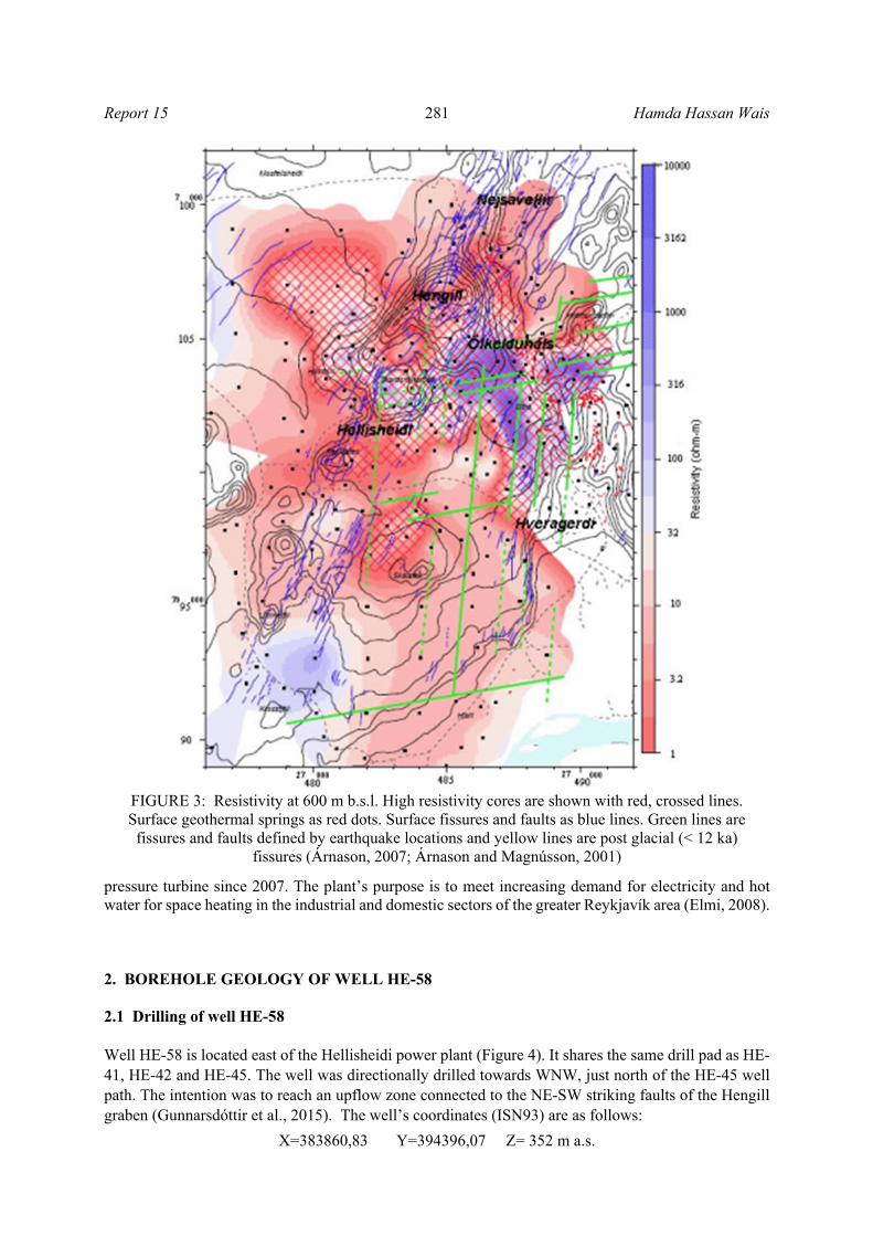
encountered. The hyaloclastite formations contain different types of rocks such as basaltic tuff, basaltic breccia and pillow basalts (glassy basalt). Approximately 550 samples were analysed using binoculars and 15 thin sections were analysed using a petrographic microscope. The lithology, geophysical loggings, some alteration minerals and temperature logs are found in Figures 6. 0 – 100 m: Cuttings were not available during this study. 100 – 152 m: Basalt breccia. Light grey to reddish, fine-grained basaltic breccia with occasional olivine, pyroxene and plagioclase crystals. Tuff lenses were seen, mostly brown palagonite. Fresh glass patches were frequently seen within the palagonite. 152 - 158 m: No cuttings due to mistakes in sampling. 158 – 258 m: Basalt breccia. Basaltic breccia, serrated and aphanitic texture. The fine- to medium-grained olivine tholeiite is mixed with slightly oxidized tuff. Crystalline fragments are slightly plagioclase and olivine phyric. Zeolites, such as mesolite and thomosonite are found at 198 m and 204 m respectively and scolecite and stilbite at 214 m and 220 m. 258 – 270 m: Glassy basalt. Mixture of grey, fine-grained basalt fragments and black glass materials. Vesicular basalt with olivine and plagioclase. The formation is not oxidized. Amorphous silica and zeolites occur. 270 – 288 m: No cuttings due to mistakes in sampling. 288 – 328 m: Glassy basalt. Pillow basalt. Plagioclase porphyritic and rather vesicular rock. Clay is noted in some of the vesicles in the glass. 328 – 354 m: Glassy basalt. Same formation as above but increasing amount of glass. Amorphous silica and clay occurs. 354 – 372 m: No cuttings due to mistakes in sampling. 372 – 398 m: Glassy basalt. Dark grey, fine- to medium-grained rock with increasing amount of glass, perhaps pillow breccia in some samples. Same alteration as before. Clay and amorphous silica occurs but zeolites are absent. 398 – 418 m: Basalt breccia. The same formation but now classified as basaltic breccia. Calcite and pyrite occur in small quantities. 418 – 660 m: Basalt tuff. Partly greenish tuff. Quartz is seen in the fractures at the depth of 430 m and crystalline quartz (rocks crystal) is found at 446 m. This unit is somewhat fractured below 450 m depth. 660 – 684 m: Basalt breccia. Dark-grey to greenish, highly altered basalt breccia, mixed with light-brown to greenish basalt tuff. The rock contains plagioclase and olivine tholeiite crystals. Wairakite occurs at a depth of 670 m. 684 – 716 m: Glassy basalt. Fine-grained olivine tholeiite basalt fragments and altered glass. Epidote occurs at 714 m along with prehnite. 716 – 726 m: No cuttings. 726 – 770 m: Glassy basalt. This sequence is moderately to highly altered. Calcite and pyrite are very common in this sequence, and quartz was identified at all depths. Veins and vesicles are filled with various unidentified minerals as they were too small.
Hamda Hassan Wais 286 Report 15
FIGURE 6: Simplified lithology and geophysical logs of well HE-58

Report 15 287 Hamda Hassan Wais
770 – 802 m: Basalt tuff. Light grey to greenish highly altered tuffs, with some dark basalt fragments. The rock is basaltic tuff with white precipitates of calcite and no oxidation. Chlorite, quartz, and chalcopyrite occur. 802 – 818 m: Basalt breccia. Light grey pillow breccia, a mixture of tuff and more crystallized olivine tholeiite. Epidote, quartz and chlorite occur at this depth. 818 – 880 m: Basalt tuff. Tuff and tuff rich breccia, cuttings are extremely fine. Coarse- and medium-grained clay, quartz, calcite and chalcopyrite are always present but epidote only occasionally. The formation is homogeneous. 880 – 894 m: No cuttings. 894 – 900 m: Basalt tuff. Light grey to greenish tuffs, with dark basalt fragments, highly altered. Same formation as above. Quartz and chalcopyrite fairly common. 900 – 910 m: Basalt breccia. Tuff rich breccia, with light grey basaltic fragments, brown tuff and calcite precipitates. Highly altered, intermediate oxidation with sub-ophitic to intergranular textures. 910 – 928 m: Basalt tuff. Same tuff formation with high alteration, mixed tuffs and breccia. Cuttings are very fine. 928 – 938 m: Glassy basalt. Pillow lava/pillow breccia. Not porous but highly altered. The rock is glassy basalt, but pillow breccia in places. Epidote, quartz and prehnite occur regularly. 938 – 946 m: Basalt tuff. Highly altered whitish tuff. The abundance of calcite increases as well as the overall alteration of the rock. 946 – 962 m: Basalt breccia. Tuff rich breccia. The tuff is highly altered, whitish and poorly bound together. A 950 m there is a sudden increase in calcite and pyrite, indicating permeability. 962 – 992 m: Basalt breccia. Tuff rich breccia, grey to greenish highly altered basalt breccia mixed with light-brown or greenish basalt tuff. Considerable increase in calcite but the amount decreases again below 980 m. 992 – 1006 m: Basalt tuff. The rock is basaltic tuff, white and highly altered. The main alteration minerals are quartz and calcite along with epidote. 1006 – 1012 m: Glassy basalt. Hypo crystalline or very finely crystallised basalt, porous and highly altered. 1012 – 1022 m: Basalt breccia. Tuff rich breccia, highly altered. Same alteration mineralogy as before although alteration minerals are very few. 1022 – 1030 m: Basalt tuff. Whitish brown tuff mixed with darker altered, fine-grained crystallized basalt. 1030 – 1046 m: Glassy basalt. Altered pillow basalt. Epidote becomes more apparent and more crystalline. Some sedimentary grains are seen. 1046 – 1050 m: Basalt tuff. White highly altered and dense tuff.
Hamda Hassan Wais 288 Report 15
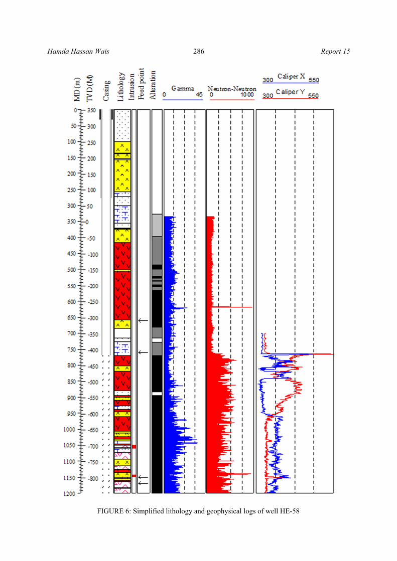
1050 – 1058 m: Fine- to medium-grained basalt. Finely crystallized basalt, possibly an intrusion, quite dense and less altered than the hyaloclastite formation above and below. Clay, calcite and pyrite are seen in vesicles. 1058 – 1072 m: Glassy basalt. Porous and very altered pillow basalt, fine grained and mixed with highly altered tuff and hypocrystalline basalt. 1072 – 1092 m: Fine-grained basalt. Fine-grained partially altered basalt. Probably a lava flow. Alteration is reduced but the alteration minerals are found in larger crystals, indicating that vesicles in this formation are larger than in the hyaloclastite formation above. 1092 – 1114 m: Basalt breccia. Tuff-rich breccia. White and very altered. Increasing amount of alteration minerals, particularly calcite. 1114 – 1126 m: Fine-grained basalt. Dense fine-grained basalt, highly altered. Most likely a lava flow. Epidote, quartz, chlorite, and calcite are the most prominent alteration minerals. 1126 – 1136 m: Basalt tuff. Highly altered, white and somewhat vesicular tuff. 1136 – 1150 m: Basalt breccia. The same formation, but with higher amount of hypocrystalline grains. 1150 – 1154 m: Fine- to medium-grained basalt. Dark, fine- to medium-grained and compact basalt, possibly an intrusion. 1160 – 1162 m: Basalt tuff. White, very altered tuff lens with high amount of alteration minerals. Wollastonite occurs at 1150 m, suggesting an alteration temperature of 260°C. The amount of calcite is reduced. 1162 – 1200 m: Fine- to medium-grained basalt. Basalt lava flow with high alteration. Potentially plagioclase phyric. Nicely crystallized alteration minerals such as epidote, quartz, calcite and prehnite are seen. 2.3.1 Intrusions An intrusion is a magma body that solidifies below the surface. They generally have relatively coarse textures compared to the host rock as the magma cools slowly to give time for crystal growth (Franzson et al., 2010). However, thin dykes may crystalize quicker resulting in fine- to medium-grained rocks. Intrusive rocks are characterized by their massive character and low alteration compared to the country rock. Indeed, two possible intrusions were identified in the uppermost 1200 m of well HE-58 (Figure 6) and these are described below:
- Intrusive unit I (1050-1058 m): This intrusion is fine to medium grained, dark grey, quite dense and much less altered than the country rock;
- Intrusive unit II (1150-1158 m): Fine- to medium-grained basaltic intrusion. The rock is light grey in colour, and characterized by plagioclase phenocrysts.
2.4 Hydrothermal alteration Hydrothermal alteration is when a change in the textural, mineralogical, and chemical composition of the host rocks occurs, caused by the action of hydrothermal fluids, steam and/or gas (Henley and Ellis, 1983). The primary minerals are replaced by secondary minerals as a result of change in the physio-chemical conditions affecting the rock. These physio-chemical changes are mainly variations in temperature, pressure, or chemical conditions. The hydrothermal minerals are geothermometers that can
Report 15 289 Hamda Hassan Wais
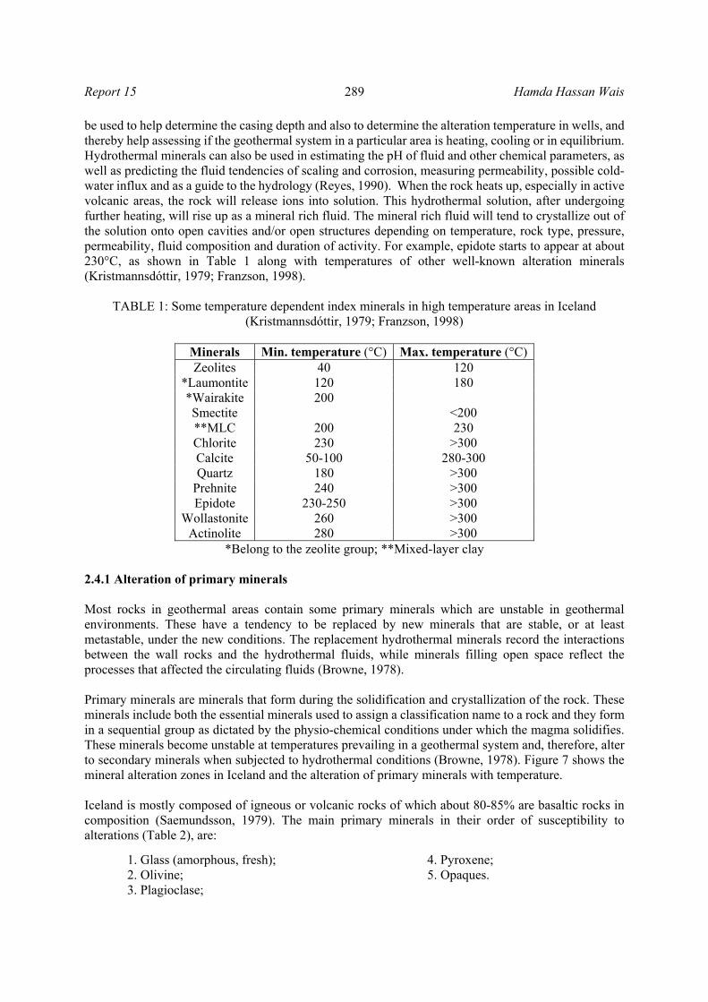
be used to help determine the casing depth and also to determine the alteration temperature in wells, and thereby help assessing if the geothermal system in a particular area is heating, cooling or in equilibrium. Hydrothermal minerals can also be used in estimating the pH of fluid and other chemical parameters, as well as predicting the fluid tendencies of scaling and corrosion, measuring permeability, possible cold-water influx and as a guide to the hydrology (Reyes, 1990). When the rock heats up, especially in active volcanic areas, the rock will release ions into solution. This hydrothermal solution, after undergoing further heating, will rise up as a mineral rich fluid. The mineral rich fluid will tend to crystallize out of the solution onto open cavities and/or open structures depending on temperature, rock type, pressure, permeability, fluid composition and duration of activity. For example, epidote starts to appear at about 230°C, as shown in Table 1 along with temperatures of other well-known alteration minerals (Kristmannsdóttir, 1979; Franzson, 1998).
TABLE 1: Some temperature dependent index minerals in high temperature areas in Iceland (Kristmannsdóttir, 1979; Franzson, 1998)
Minerals Min. temperature (°C) Max. temperature (°C) Zeolites 40 120
*Laumontite 120 180 *Wairakite 200 Smectite <200 **MLC 200 230 Chlorite 230 >300 Calcite 50-100 280-300 Quartz 180 >300
Prehnite 240 >300 Epidote 230-250 >300
Wollastonite 260 >300 Actinolite 280 >300
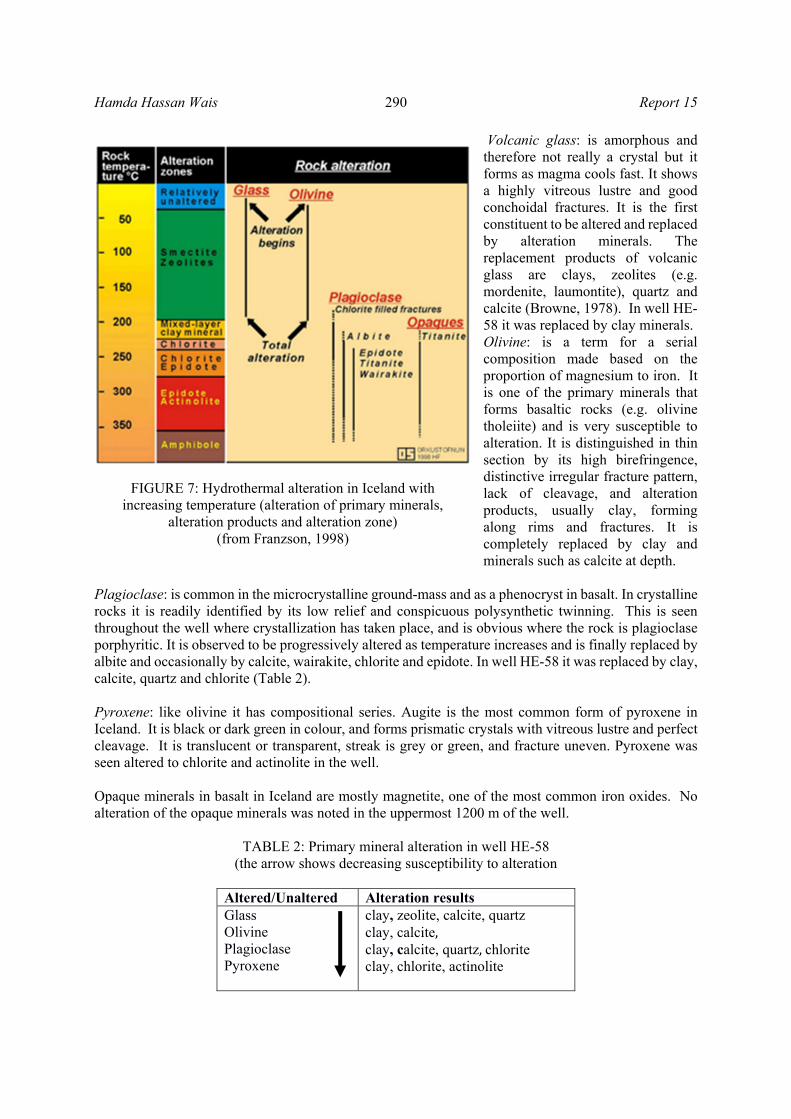
*Belong to the zeolite group; **Mixed-layer clay 2.4.1 Alteration of primary minerals Most rocks in geothermal areas contain some primary minerals which are unstable in geothermal environments. These have a tendency to be replaced by new minerals that are stable, or at least metastable, under the new conditions. The replacement hydrothermal minerals record the interactions between the wall rocks and the hydrothermal fluids, while minerals filling open space reflect the processes that affected the circulating fluids (Browne, 1978). Primary minerals are minerals that form during the solidification and crystallization of the rock. These minerals include both the essential minerals used to assign a classification name to a rock and they form in a sequential group as dictated by the physio-chemical conditions under which the magma solidifies. These minerals become unstable at temperatures prevailing in a geothermal system and, therefore, alter to secondary minerals when subjected to hydrothermal conditions (Browne, 1978). Figure 7 shows the mineral alteration zones in Iceland and the alteration of primary minerals with temperature. Iceland is mostly composed of igneous or volcanic rocks of which about 80-85% are basaltic rocks in composition (Saemundsson, 1979). The main primary minerals in their order of susceptibility to alterations (Table 2), are:
1. Glass (amorphous, fresh); 4. Pyroxene; 2. Olivine; 5. Opaques. 3. Plagioclase;
Hamda Hassan Wais 290 Report 15
Volcanic glass: is amorphous and therefore not really a crystal but it forms as magma cools fast. It shows a highly vitreous lustre and good conchoidal fractures. It is the first constituent to be altered and replaced by alteration minerals. The replacement products of volcanic glass are clays, zeolites (e.g. mordenite, laumontite), quartz and calcite (Browne, 1978). In well HE-58 it was replaced by clay minerals. Olivine: is a term for a serial composition made based on the proportion of magnesium to iron. It is one of the primary minerals that forms basaltic rocks (e.g. olivine tholeiite) and is very susceptible to alteration. It is distinguished in thin section by its high birefringence, distinctive irregular fracture pattern, lack of cleavage, and alteration products, usually clay, forming along rims and fractures. It is completely replaced by clay and minerals such as calcite at depth.
Plagioclase: is common in the microcrystalline ground-mass and as a phenocryst in basalt. In crystalline rocks it is readily identified by its low relief and conspicuous polysynthetic twinning. This is seen throughout the well where crystallization has taken place, and is obvious where the rock is plagioclase porphyritic. It is observed to be progressively altered as temperature increases and is finally replaced by albite and occasionally by calcite, wairakite, chlorite and epidote. In well HE-58 it was replaced by clay, calcite, quartz and chlorite (Table 2). Pyroxene: like olivine it has compositional series. Augite is the most common form of pyroxene in Iceland. It is black or dark green in colour, and forms prismatic crystals with vitreous lustre and perfect cleavage. It is translucent or transparent, streak is grey or green, and fracture uneven. Pyroxene was seen altered to chlorite and actinolite in the well. Opaque minerals in basalt in Iceland are mostly magnetite, one of the most common iron oxides. No alteration of the opaque minerals was noted in the uppermost 1200 m of the well.
TABLE 2: Primary mineral alteration in well HE-58 (the arrow shows decreasing susceptibility to alteration
Altered/Unaltered Alteration results Glass Olivine Plagioclase Pyroxene
clay, zeolite, calcite, quartz clay, calcite, clay, calcite, quartz,chlorite clay, chlorite, actinolite
FIGURE 7: Hydrothermal alteration in Iceland with increasing temperature (alteration of primary minerals,
alteration products and alteration zone) (from Franzson, 1998)

Report 15 291 Hamda Hassan Wais
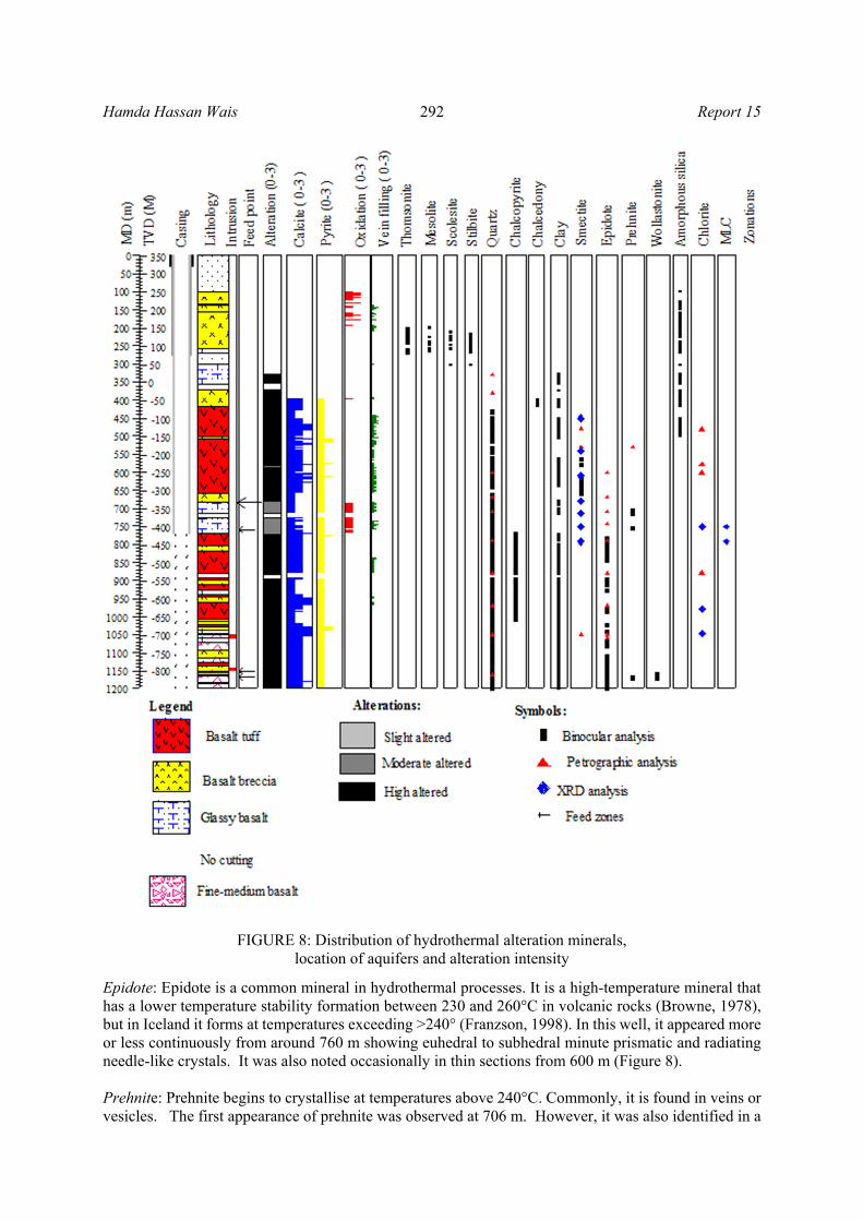
2.4.2 Distribution of alteration minerals Hydrothermal minerals are formed as a result of the alteration of primary minerals. Hydrothermal alteration depends on many factors or parameter such as temperature, permeability, fluid chemistry, rock type, pressure and rock structure (Kristmannsdóttir, 1978; Reyes, 1990; Browne, 1978; Malapitan, 1995). In well HE-58, different hydrothermal minerals were observed, but the most common minerals in the upper 1200 m were calcite, pyrite, zeolites, chalcedony, chalcopyrite, epidote, quartz, clay, prehnite, chlorite and wollastonite. A geothermal system is always associated with H2S and CO2, which contribute to the forming of calcite and pyrite. A description of the alteration minerals along with their occurrence in the well is described below and their distribution is shown in Figure 8: Calcite. It is one of the most abundant and widely distributed secondary minerals in the well, appearing from 398 m and seen all the way to the bottom of the 1200 m section of the well. It is frequently seen in the pores of hyaloclastite units and lava flows, but less in the more compact intrusions. Calcite either occurs as a replacement of primary minerals or as a direct depositional mineral. Hydrochloric acid was used to identify it in the cuttings. Pyrite. Some pyrite is seen in most samples below ca. 400 m in the well but never abundant. It occurs as precipitation in veins, vesicule and chalcopyrite. Chalcedony. Chalcedony is one of the varieties of silica polymorphs that have temperature equilibrium of less than 180°C (Fournier, 1985). It occurs at around 400 m in well HE-58. In thin sections, it can be seen as a thin-layered lining in vesicles. All of the minerals below are associated with certain temperatures in geothermal systems in Iceland and can be used to identify the thermal evolution of the system: Zeolites: are hydrous secondary minerals (sodium calcium aluminium silicates). Zeolites are generally white or colourless, but sometimes yellow by minor impurities. Zeolites both occur as precipitations in vesicles as well as replacing glass and sometimes plagioclase. In nature, zeolites are temperature dependent which can help in determining the temperature at a given depth in geothermal systems. In well HE-58 zeolites appear at 198 m and can be found down to 302 m. The different types of zeolites in well HE-58 are described below:
Mesolite: It was found with binocular microscope at depths of 198 m, 226 m, 242 m, 256 m, 260 m and 264 m. It is characterised by fibrous radiating clusters. Mesolite is finer and fainter in colour when compared to scolecite in a petrographic microscope. It forms at approximately 70°C; Thomsonite: This member of the zeolite family was observed in the binocular microscope at 204 m, 212 m, 218 m, 228 m, 232 m, 240 m, 262 m, and 268 m. It has radiating, elongated and slightly flattened crystal habit. Thomsonite crystallises at around 40°C; Scolecite: It was found with binocular microscope at 210 m, 214 m, 222-226 m, 230 m, 234 m, 246-248 m, 258-260 m, and with the last appearance at 302 m. Scolecite precipitates between 70 and 120°C; Stilbite: Under the microscope, stilbite is characteristically radial and with fan-like aggregates, and shows good cleavage. Stilbite was found at these depth intervals 216-236 m, and 248-270 m and is indicative of the temperature range 90-120°C.
Quartz: It is a white, transparent mineral. Quartz was first seen at a depth of about 430 m and continued to the bottom of the well. It was also noted in thin sections at 380 m and 600 m (Figure 8). Quartz forms at temperature above 180°C.
Hamda Hassan Wais 292 Report 15
Epidote: Epidote is a common mineral in hydrothermal processes. It is a high-temperature mineral that has a lower temperature stability formation between 230 and 260°C in volcanic rocks (Browne, 1978), but in Iceland it forms at temperatures exceeding >240° (Franzson, 1998). In this well, it appeared more or less continuously from around 760 m showing euhedral to subhedral minute prismatic and radiating needle-like crystals. It was also noted occasionally in thin sections from 600 m (Figure 8). Prehnite: Prehnite begins to crystallise at temperatures above 240°C. Commonly, it is found in veins or vesicles. The first appearance of prehnite was observed at 706 m. However, it was also identified in a
FIGURE 8: Distribution of hydrothermal alteration minerals, location of aquifers and alteration intensity
Report 15 293 Hamda Hassan Wais
thin section at 530 m. Normally, prehnite occurs along with epidote and other high temperature minerals and as a part of simple to complex mineral assemblages. Wollastonite: a hairy-like high-temperature mineral, first appearance was at the interval depth of 1160-1170 m. In the thin sections, wollastonite seemed to crystallise after epidote. The upper boundary of wollastonite indicates a temperature of around 260°C. Clay minerals: The clay minerals are the most voluminous alteration minerals. Their formation involves the chemical reactions and physical movement of hydrothermal fluids and, in many cases, there is a zonal arrangement of the clay minerals around the source of alteration, depending on the parent rock and the nature of the hydrothermal solutions (Gebrehiwot, 2010). The composition, structure and morphology of clay minerals depend on a number of environmental parameters – temperature, fluid composition/amount, pH, etc. (Njue, 2010). Clay minerals are alteration products of basaltic glass, olivine, plagioclase, and partly pyroxene, as well as vesicle fillings. Smectite, mixed-layer clays and chlorite comprise the different types of clays in the well:
Smectite is a low-temperature clay formed by the alteration of glass and ferromagnesian primary minerals such as olivine, commonly replacing them completely (Lugaizi, 2011). Smectite has a brownish colour and is found in patches or as thin coatings in altered rocks. In well HE-58 it was first found at 450 m depth (XRD). Under the petrographic microscope, smectite is fine grained with a dark-brownish colour. Mixed-layer clays: Mixed-layer clay (MLC) minerals are intermediate products of pure end-members of clays (Sradon, 1999) most commonly forming interlayers of smectite and chlorite in Icelandic rocks. MLC was identified in two XRD samples at 752 m and 792 m (Figure 8). Chlorite: The presence of chlorite indicates temperatures above 230°C (Franzson, 1998). Under the petrographic microscope, the mineral appears light-green and non-pleochroic in plane polarized light; under crossed polars it is greyish. Chlorite was identified in thin sections from 480 m and with XRD analysis from 752 m (Figure 8).
2.4.3 Alteration zones Many hydrothermal minerals in Iceland are highly temperature dependent and definite mineralogical changes are seen to take place with increasing temperature (Kristmannsdóttir and Tómasson, 1978; Malapitan, 1995). In the Icelandic geothermal setting, low-temperature zeolites and amorphous silica form below 120°C, chalcedony below 180°C, quartz above 180°C, wairakite above 200°C, epidote above 230-250°C and garnet and amphibole above 280°C (Kristmannsdóttir, 1979; Saemundsson and Gunnlaugsson, 2002; Franzson, 1998). Clay minerals such as smectite crystallize below 200°C, mixed-layer clays at 200-230°C, and chlorite above 230°C (Kristmannsdóttir, 1977). Based on binocular, petrographic and XRD analysis, four alteration zones were distinguished in HE-58 (Figure 9). The zones were revealed by considering the distribution of secondary minerals as well as the abundance of certain minerals. Alteration zones in well HE-58 are: Unaltered zone (0-200 m): This zone is composed of fresh rocks with almost no signature of alteration or precipitation of secondary minerals other than cold groundwater minerals. The zone is signified by low-temperature minerals from 0 to 50°C. Zeolite-smectite (200-450 m): Low-temperature alteration zone which is characterized by the presence of zeolites and low-temperature clays (smectite). The upper boundary of this zone is represented by the first appearance of zeolites at 200 m. The zeolites present as secondary minerals in this zone are commonly thomsonite/mesolite, stilbite and scolecite. Smectite indicates temperature less than 200°C and is first found in XRD analysis at around 450 m.

Hamda Hassan Wais 294 Report 15
Chlorite zone (450-760 m): Chlorite is a high-temperature clay mineral which signifies temperature above 230°C and its first appearance marks the top boundary of this zone (Browne, 1978; Franzson, 1987). Chlorite is first identified in thin section at around 480 m but XRD analysis shows chlorite at around 752 m. Chlorite-epidote zone (760-1200 m): This alteration zone is composed of high temperature secondary minerals such quartz, epidote and chlorite. Mixed-layer clay is also identified in XRD analysis at the same depth as chlorite appears in XRD. Wollastonite appears at around 1160 m (260°C). The characteristic temperature range of this zone in Iceland is about 250-280°C. The upper boundary of this zone was determined from the depth where epidote became common.
FIGURE 9: Alteration minerals and alteration zones of well HE-58

Report 15 295 Hamda Hassan Wais
3. AQUIFERS Aquifers are typically water-saturated regions in the subsurface which produce quantities of water to a well. The movement of subsurface water is controlled by the type of rock formations, the characteristics of its permeability and porosity, the temperature and pressure of the subsurface environment, natural recharge, and the hydraulic gradient. The presence of structural formations such as faults, fractures, and joints, lithological contacts, clasts and fragmented matrixes, and paleosols are positive indications of geothermal feed zones (Reyes, 2000). Pillow basalts have higher effective permeability than any other rock type encountered by drilling in Icelandic geothermal areas (Fridleifsson, 1978). Loss of circulation may vary from minor or weak lossesto total circulation losses that are characterized by highly permeable formations. In the geothermal settings of Iceland, the highest permeable zones intercepted are associated with dykes and faults (Arnórsson, 1995; Pendon, 2006). In well HE-58, the permeable zones were identified by temperature and geophysical logs (caliper, neutron and gamma logs), increasing alteration minerals (e.g. calcite and pyrite), and circulation losses. Four possible permeable zones were identified at 660 m, 750 m, 1050 m, and 1150 m and they are described below:
Aquifer 1: This feed zone, at around 660 m, was identified by a temperature increase in logs from the 30th of August and 16th of September (Figure 10), located in a tuff and breccia formation. Aquifer 2: This feed zone is at around 760 m, identified by an increase in temperature and a high peak in the caliper log (Figures 10 and 6). At 770 m (uncorrected depth) there is a lithological contact between glassy basalt and a tuff formation, both rich in calcite and pyrite. Aquifer 3: This aquifer is at 1050 m indicated by a small increase in temperature, slight peak in the caliper log and a high peak in the gamma ray log as well (Figures 10 and 6). At 1050-1058 m there is a possible intrusion present and there is an increase in both calcite and epidote around that depth. Aquifer 4: This permeable zone is located at approximately 1150 m in highly altered basaltic breccia, but also rather close to a possible intrusion at 1150-1154 m. The aquifer was seen by an increase in the temperature log from the 3rd of September (Figure 10) and high peak in the caliper log and neutron log (Figure 6). At this depth there is an increase in calcite and epidote and at 1160 m (uncorrected depth) there is significant alteration and abundant wollastonite.
FIGURE 10: Temperature logs from HE-58 while injecting 25 l/s (green), injecting 15 l/s during injectivity test (red) and following stimulation
(black) showing the location of permeable zones
Hamda Hassan Wais 296 Report 15
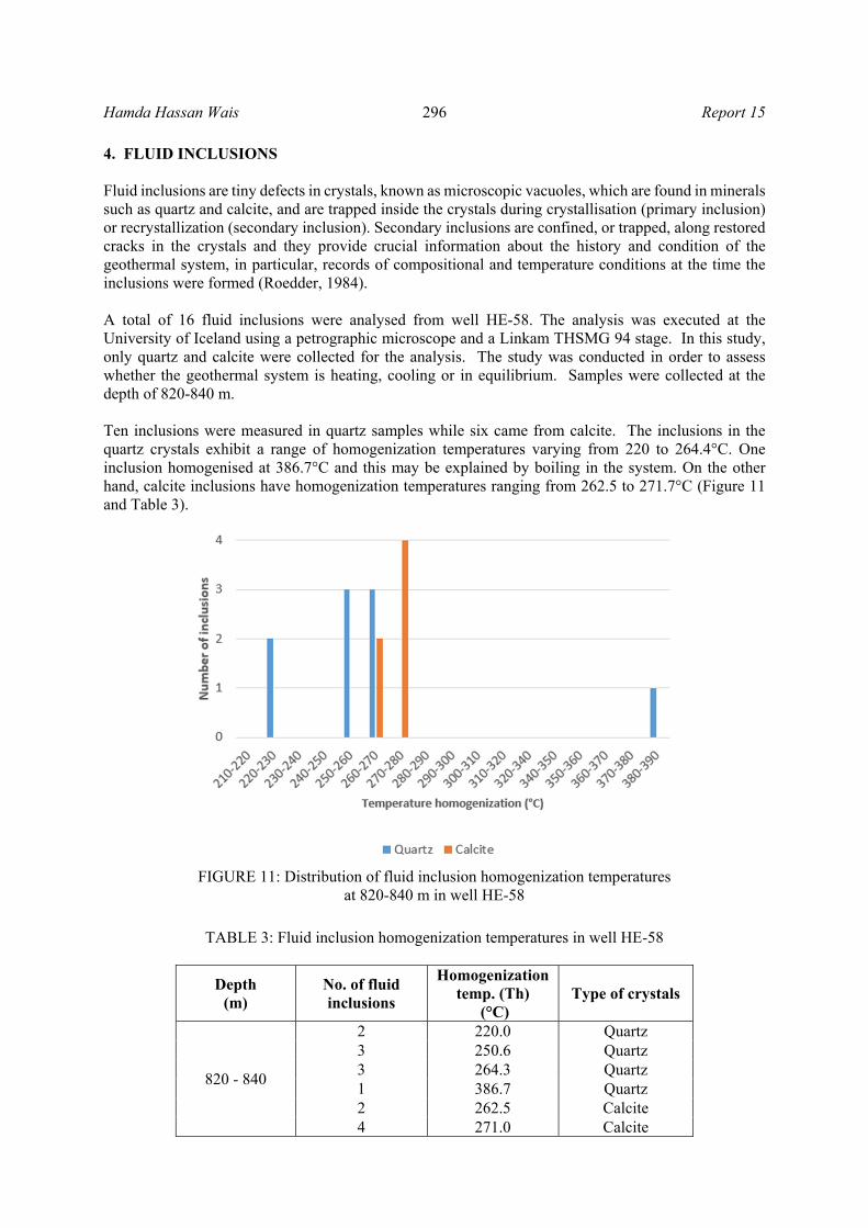
4. FLUID INCLUSIONS Fluid inclusions are tiny defects in crystals, known as microscopic vacuoles, which are found in minerals such as quartz and calcite, and are trapped inside the crystals during crystallisation (primary inclusion) or recrystallization (secondary inclusion). Secondary inclusions are confined, or trapped, along restored cracks in the crystals and they provide crucial information about the history and condition of the geothermal system, in particular, records of compositional and temperature conditions at the time the inclusions were formed (Roedder, 1984). A total of 16 fluid inclusions were analysed from well HE-58. The analysis was executed at the University of Iceland using a petrographic microscope and a Linkam THSMG 94 stage. In this study, only quartz and calcite were collected for the analysis. The study was conducted in order to assess whether the geothermal system is heating, cooling or in equilibrium. Samples were collected at the depth of 820-840 m. Ten inclusions were measured in quartz samples while six came from calcite. The inclusions in the quartz crystals exhibit a range of homogenization temperatures varying from 220 to 264.4°C. One inclusion homogenised at 386.7°C and this may be explained by boiling in the system. On the other hand, calcite inclusions have homogenization temperatures ranging from 262.5 to 271.7°C (Figure 11 and Table 3).
TABLE 3: Fluid inclusion homogenization temperatures in well HE-58
Depth (m)
No. of fluid inclusions
Homogenization temp. (Th)
(°C) Type of crystals
820 - 840
2 220.0 Quartz 3 250.6 Quartz 3 264.3 Quartz 1 386.7 Quartz 2 262.5 Calcite 4 271.0 Calcite
FIGURE 11: Distribution of fluid inclusion homogenization temperatures at 820-840 m in well HE-58
Report 15 297 Hamda Hassan Wais
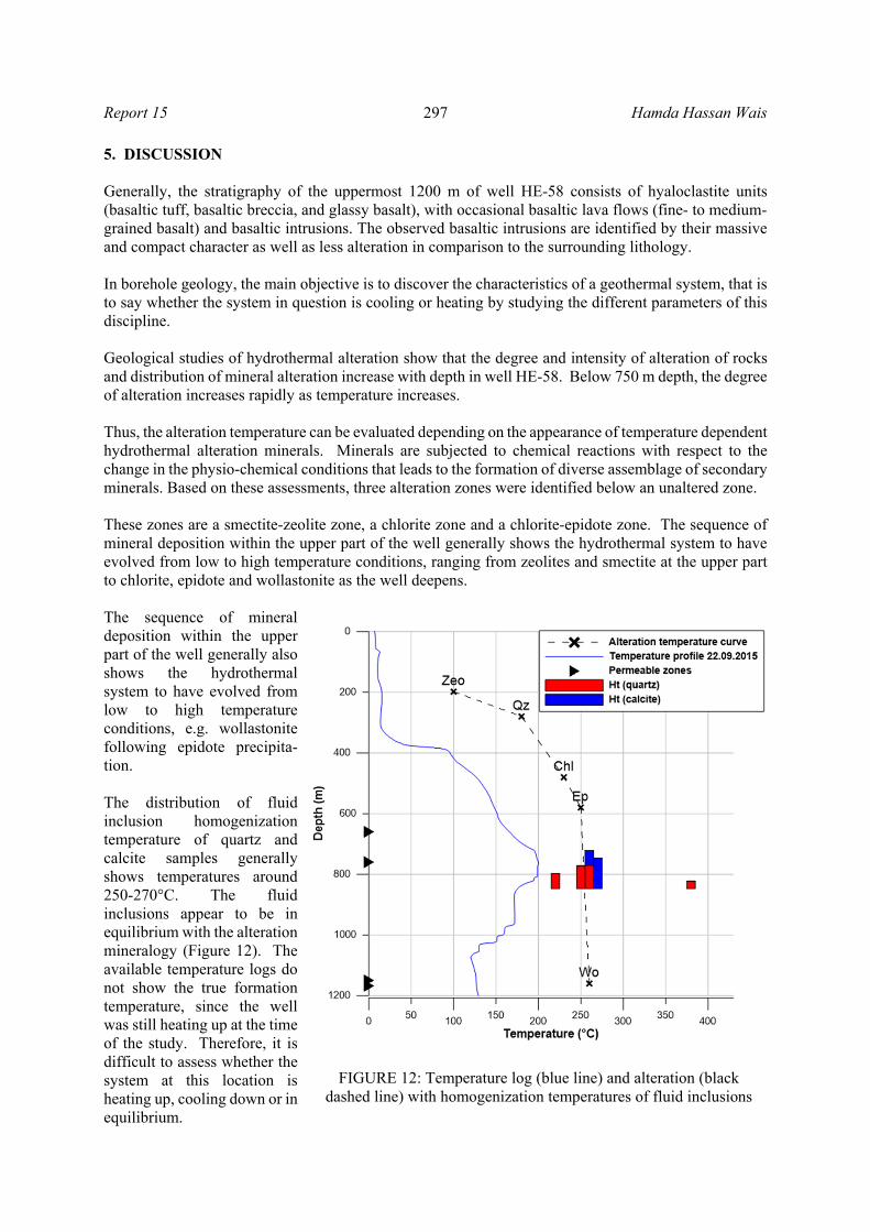
5. DISCUSSION Generally, the stratigraphy of the uppermost 1200 m of well HE-58 consists of hyaloclastite units (basaltic tuff, basaltic breccia, and glassy basalt), with occasional basaltic lava flows (fine- to medium-grained basalt) and basaltic intrusions. The observed basaltic intrusions are identified by their massive and compact character as well as less alteration in comparison to the surrounding lithology. In borehole geology, the main objective is to discover the characteristics of a geothermal system, that is to say whether the system in question is cooling or heating by studying the different parameters of this discipline. Geological studies of hydrothermal alteration show that the degree and intensity of alteration of rocks and distribution of mineral alteration increase with depth in well HE-58. Below 750 m depth, the degree of alteration increases rapidly as temperature increases. Thus, the alteration temperature can be evaluated depending on the appearance of temperature dependent hydrothermal alteration minerals. Minerals are subjected to chemical reactions with respect to the change in the physio-chemical conditions that leads to the formation of diverse assemblage of secondary minerals. Based on these assessments, three alteration zones were identified below an unaltered zone. These zones are a smectite-zeolite zone, a chlorite zone and a chlorite-epidote zone. The sequence of mineral deposition within the upper part of the well generally shows the hydrothermal system to have evolved from low to high temperature conditions, ranging from zeolites and smectite at the upper part to chlorite, epidote and wollastonite as the well deepens. The sequence of mineral deposition within the upper part of the well generally also shows the hydrothermal system to have evolved from low to high temperature conditions, e.g. wollastonite following epidote precipita-tion. The distribution of fluid inclusion homogenization temperature of quartz and calcite samples generally shows temperatures around 250-270°C. The fluid inclusions appear to be in equilibrium with the alteration mineralogy (Figure 12). The available temperature logs do not show the true formation temperature, since the well was still heating up at the time of the study. Therefore, it is difficult to assess whether the system at this location is heating up, cooling down or in equilibrium.
FIGURE 12: Temperature log (blue line) and alteration (black dashed line) with homogenization temperatures of fluid inclusions

Hamda Hassan Wais 298 Report 15
6. CONCLUSIONS The following conclusions can be deduced from the geological study of well HE- 58:
The stratigraphy of the first 1200 m of well HE-58 consist of hyaloclastite formation (basaltic breccia, basaltic tuff and glassy basaltic), some crystalline basaltic lava flow (fine- to medium-grained basalt), and a couple of possible basaltic intrusions.
Alteration mineral distribution shows a general tendency to gradual increasing alteration with depth where low-temperature minerals such as zeolites, are gradually replaced by moderate temperature minerals such as quartz, which are quickly followed by high temperature mineral assemblages such as chlorite, prehnite, epidote and wollastonite.
According to the distribution of alteration minerals, four alteration zone were identified and arranged according to the first appearance of key index minerals. Unaltered zone (<50°C), a zeolite-smectite zone (<200°C), a chlorite zone (230-250°C) and a chlorite-epidote zone (250-280°C).
Based on the geophysical logs and the intensity of alteration, four permeable zones were distinguished, located at 660 m, 760 m, 1050 m and 1150 m.
Fluid inclusion temperature at 820-840 m is generally between 250 and 270°C. When compared to the prevailing alteration temperature at that depth, we can deduce that the fluid inclusions appear to be in equilibrium with the alteration mineralogy. Comparison with the formation temperature was not possible as the well was still heating up at the time of this study.
ACKNOWLEDGEMENTS I wish to express my sincere gratitude to the Government of Iceland and the United Nations University (UNU), for granting me a fellowship to undertake specialized training at the UNU-Geothermal Training Programme. Indeed, the success and final outcome of this project required a lot of guidance and assistance from many people and I am extremely fortunate to have gotten this for the completion of my project. That I have done this is only due to such guidance and assistance and I will not forget to thank them. Special thanks to the UNU-GTP Director, Dr. Lúdvík S. Georgsson for awarding me the opportunity to study in Iceland; many thanks to Mr. Ingimar Gudni Haraldsson, Ms. Málfrídur Ómarsdóttir, Mr. Markús A.G. Wilde, Ms. Thórhildur Ísberg and Ms. María Gudjónsdóttir for their support and help in the programme. My heartfelt and sincere thanks also go to my supervisor, Dr. Björn S. Hardarson and my second supervisor Ms. Helga Margrét Helgadóttir, for their excellent supervision, their cordial helpfulness, valuable advice and encouragement during the entire project period. I would like to thank all the lecturers and the staff members at Orkustofnun and ISOR for the knowledge, assistance and valuable comments given to us during the lecture sessions. I also thank the dear UNU Fellows of 2015 for their unbelievable friendship and cooperation during our training time, especially my brothers and gentlemen geologists. My very sincere gratitude goes to my wonderful amazing family, sisters, brothers and friends, especially my lovely mom, my beloved auntie and the first man in my life my dad for their encouragement and motivation. Above all, I praise God, the almighty for providing me with this opportunity and granting me the capability to proceed successfully.

Report 15 299 Hamda Hassan Wais
REFERENCES Árnason, K., Karlsdóttir, R., Eysteinsson, H., Flóvenz, Ó.G., and Gudlaugsson, S.Th., 2000: The resistivity structure of high-temperature geothermal systems in Iceland. Proceedings of the World Geothermal Congress 2000, Kyushu-Tohoku, Japan, 923-928. Árnason, K., and Magnússon, I.Th., 2001: Geothermal activity in the Hengill area. Results from resistivity mapping. Orkustofnun, Reykjavik, report, OS-2001/091 (in Icelandic with English abstract), 250 pp. Arnórsson, S., 1995: Geothermal systems in Iceland; structures and conceptual models; I, high temperature areas. Geothermics, 24, 561-602. Björnsson, A., Hersir, G.P., and Björnsson, G., 1986: The Hengill high-temperature area SW-Iceland: Regional geophysical survey. Geothermal Resources Council, Trans., 10, 205-210. Björnsson, G., Hjartarson, A., Bödvarsson, G.S., and Steingrímsson, B., 2003: Development of a 3-D geothermal reservoir model for the Greater Hengil volcano in SW-Iceland. Proceedings of TOUGH Symposium 2003, Lawrence Berkeley Laboratory, Berkeley, California, USA, 11 pp. Browne, P.R.L., 1978: Hydrothermal alteration in active geothermal fields. Annual Reviews of Earth and Planetary Science, 6, 229-250. Elmi H., D., 2008: Geothermal resource assessment through well testing and production response. University of Iceland, MSc thesis, UNU-GTP, report 1, 73 pp. Franzson, H., 1987: The Eldvörp high-temperature area, SW Iceland. Geothermal geology of the first exploration well. Proceedings of the 9th New Zealand Geothermal Workshop, Auckland, NZ, 179-185. Franzson, H., 1998: Reservoir geology of the Nesjavellir high-temperature field in SW-Iceland. Proceedings of the 19th Annual PNOC-EDC Geothermal Conference, Manila, 13-20. Franzson, H., Árnason, K., Saemundsson, K., Steingrímsson B., and Gunnlaugsson E., 2010: The Hengill geothermal system, conceptual model and thermal evolution. Proceedings of the World Geothermal Congress 2010, Bali, Indonesia, 9 pp. Franzson, H., Kristjánsson, B.R., Gunnarsson, G., Björnsson, G., Hjartarson, A., Steingrímsson, B., Gunnlaugsson, E., and Gíslason G., 2005: The Hengill Hellisheidi geothermal field. Development of a conceptual geothermal model. Proceedings World Geothermal Congress 2005, Antalya, Turkey, CD, 7 pp. Fridleifsson, I.B, 1978: Applied volcanology in geothermal exploration in Iceland. Pageoph, 117, 242- 252. Fridleifsson, I.B., 1979: Geothermal activity in Iceland. Jökull, 29, 47-56. Gebrehiwot Mesfin, K., 2010: Subsurface geology, hydrothermal alteration and geothermal model of northern Skardsmýrarfjall, Hellisheidi geothermal field. University of Iceland, MSc thesis, UNU-GTP, report 5, 65 pp Gunnarsson, G., 2011: A story of success and failures, mastering reinjection in the Hellisheidi field,SW-Iceland. Proceedings of the 36th Workshop on Geothermal Reservoir Engineering, Stanford University, Stanford, Ca, 8 pp.

Hamda Hassan Wais 300 Report 15
Gunnarsdóttir, S.H., Tryggvason, H. and Hardarson, B.S., 2015: Pre-drilling, 1st and 2nd sections: Drilling for surface casing to 98 m, safety casing to 289 m and production casing to 769 m depth. ÍSOR - Iceland GeoSurvey, report ÍSOR-2015/044 (in Icelandic). Henley, R.W. and Ellis, A.J. 1983: Geothermal systems ancient and modern: a geochemical review. Earth Science and Reviews, 19, 1-50. Kristmannsdóttir, H., and Tómasson, J., 1978: Zeolite zones in geothermal areas in Iceland. In: Sand, L.B., and Mumpton (eds.), Natural zeolites, occurrence, properties, use. Pergamon Press Ltd., 277- 284. Kristmannsdóttir, H., 1977: Types of clay minerals in altered basaltic rocks, Reykjanes, Iceland (in Icelandic). Jökull, 26, 3-39. Kristmannsdóttir, H., 1979: Alteration of basaltic rocks by hydrothermal activity at 100-300°C. In: Mortland, M.M., and Farmer, V.C. (editors). International Clay Conference 1978. Elsevier Scientific Publishing Co., Amsterdam, 359-367. Malapitan, R.T., 1995: Borehole geology and hydrothermal alteration of well KR-9, Krýsuvík, SWIceland. Report 8 in: Geothermal Training in Iceland 1995. UNU-GTP, Iceland, 185-206. Njue, M.L.M., 2010: Borehole geology and hydrothermal mineralisation of well HE-27, Hellisheidi geothermal field, SW-Iceland. Report 24 in: Geothermal training in Iceland 2010. UNU-GTP, Iceland, 463-492. Lugaizi. I., 2011: Borehole geology and hydrothermal mineralisation of well HE-32, Hellisheidi geothermal field, SW-Iceland. Report 20 in: Geothermal training in Iceland 2011. UNU-GTP, Iceland, 417-465. Pendon, R.R., 2006: Borehole geology and hydrothermal mineralisation of well HE-22, Ölkelduháls field, Hengill area, SW-Iceland. Report 17 in: Geothermal training in Iceland 2006. UNU-GTP, Iceland, 357-390. Reyes, A.G., 1990: Petrology of Philippine geothermal systems and the application of alteration mineralogy to their assessment. J. Volc. Geoth. Res., 43, 279-309. Reyes, A.G., 2000: Petrology and mineral alteration in hydrothermal systems: from diagenesis to volcanic catastrophes. UNU-GTP, Iceland, report 18-1998, 77 pp. Roedder, E., 1984: Fluid inclusions. Mineralogical Society of America, Washington, DC, Reviews in Mineralogy, 12, 646 pp Saemundsson, K., and Gunnlaugsson, E., 2002: Icelandic rocks and minerals. Edda and Media Publishing, Reykjavík, Iceland, 233 pp. Saemundsson, K., 1979: Outline of the geology of Iceland. Jökull, 29, 7-28. Saemundsson, K., 1967: Vulkanismus und Tektonik des Hengill-Gebietes in Sudwest-Island. Acta Nat. Isl., II-7 (in German), 195 pp. Sradon, J., 1999: Nature of mixed-layer clays and mechanisms of their formation and alteration. Annu. Rev. Earth Planet. Sci., 27, 19-53.
Report 15 301 Hamda Hassan Wais
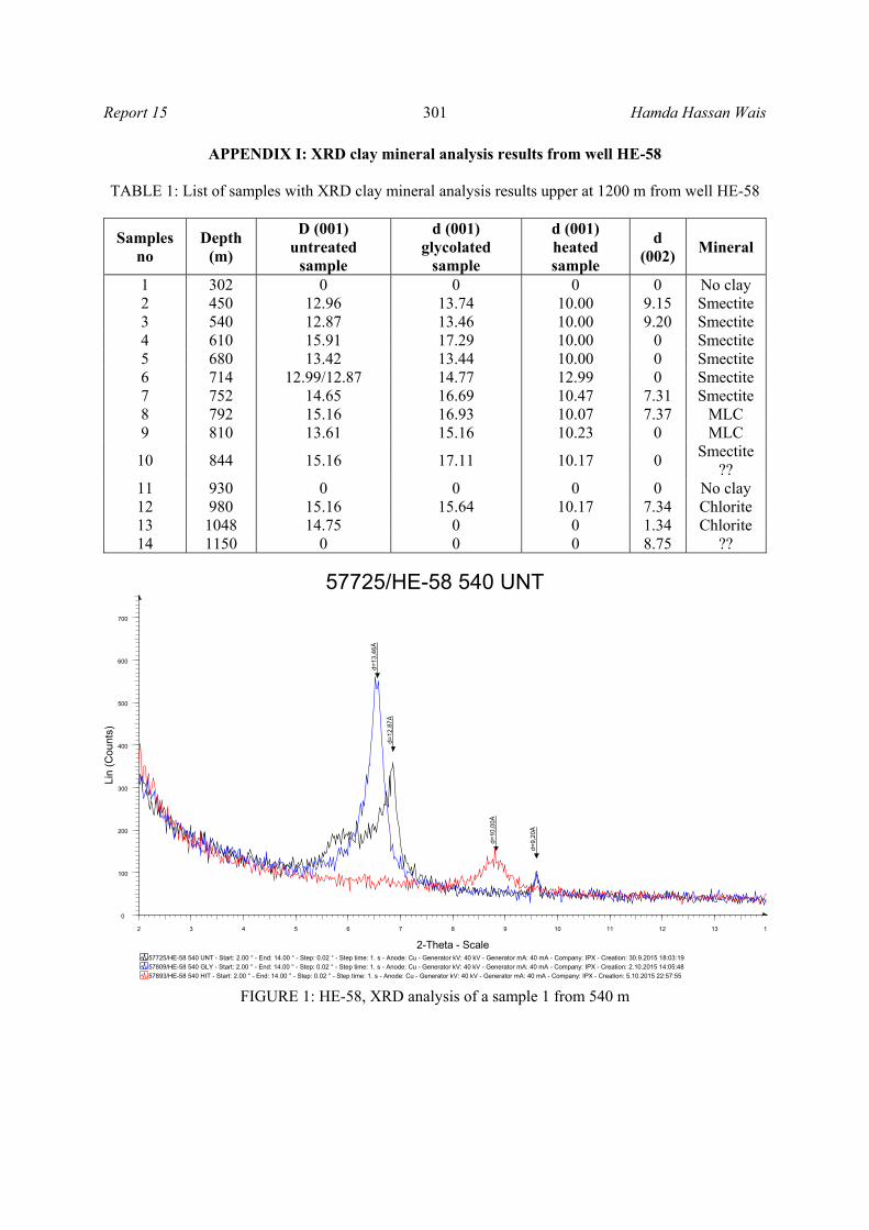
APPENDIX I: XRD clay mineral analysis results from well HE-58 TABLE 1: List of samples with XRD clay mineral analysis results upper at 1200 m from well HE-58
Samples no
Depth (m)
D (001) untreated
sample
d (001) glycolated
sample
d (001) heated sample
d (002)
Mineral
1 302 0 0 0 0 No clay 2 450 12.96 13.74 10.00 9.15 Smectite 3 540 12.87 13.46 10.00 9.20 Smectite 4 610 15.91 17.29 10.00 0 Smectite 5 680 13.42 13.44 10.00 0 Smectite 6 714 12.99/12.87 14.77 12.99 0 Smectite 7 752 14.65 16.69 10.47 7.31 Smectite 8 792 15.16 16.93 10.07 7.37 MLC 9 810 13.61 15.16 10.23 0 MLC
10 844 15.16 17.11 10.17 0 Smectite
?? 11 930 0 0 0 0 No clay 12 980 15.16 15.64 10.17 7.34 Chlorite 13 1048 14.75 0 0 1.34 Chlorite 14 1150 0 0 0 8.75 ??
FIGURE 1: HE-58, XRD analysis of a sample 1 from 540 m
57725/HE-58 540 UNT
57893/HE-58 540 HIT - Start: 2.00 ° - End: 14.00 ° - Step: 0.02 ° - Step time: 1. s - Anode: Cu - Generator kV: 40 kV - Generator mA: 40 mA - Company: IPX - Creation: 5.10.2015 22:57:55
57809/HE-58 540 GLY - Start: 2.00 ° - End: 14.00 ° - Step: 0.02 ° - Step time: 1. s - Anode: Cu - Generator kV: 40 kV - Generator mA: 40 mA - Company: IPX - Creation: 2.10.2015 14:05:48
57725/HE-58 540 UNT - Start: 2.00 ° - End: 14.00 ° - Step: 0.02 ° - Step time: 1. s - Anode: Cu - Generator kV: 40 kV - Generator mA: 40 mA - Company: IPX - Creation: 30.9.2015 18:03:19
Lin
(C
ount
s)
0
100
200
300
400
500
600
700
2-Theta - Scale
2 3 4 5 6 7 8 9 10 11 12 13 1
d=10
,00Å
d=1
2,87
Å
d=13
,46Å
d=9,
20Å

Hamda Hassan Wais 302 Report 15
FIGURE 2: HE-58, XRD analysis from 752 m
FIGURE 3: HE-58, XRD analysis from 980 m
57729/HE-58 752 UNT
57897/HE-58 752 HIT - Start: 2.00 ° - End: 14.00 ° - Step: 0.02 ° - Step time: 1. s - Anode: Cu - Generator kV: 40 kV - Generator mA: 40 mA - Company: IPX - Creation: 5.10.2015 23:40:15
57813/HE-58 752 GLY - Start: 2.00 ° - End: 14.00 ° - Step: 0.02 ° - Step time: 1. s - Anode: Cu - Generator kV: 40 kV - Generator mA: 40 mA - Company: IPX - Creation: 2.10.2015 14:48:06
57729/HE-58 752 UNT - Start: 2.00 ° - End: 14.00 ° - Step: 0.02 ° - Step time: 1. s - Anode: Cu - Generator kV: 40 kV - Generator mA: 40 mA - Company: IPX - Creation: 30.9.2015 18:45:37
Lin
(C
ount
s)
0
100
200
300
400
500
600
700
800
2-Theta - Scale
2 3 4 5 6 7 8 9 10 11 12 13 1
d=
10,
08Å
d=
12,
47Å
d=12
,99Å
d=
30,8
0Å
d=
7,3
1Å
d=31
,92Å
d=15
,32Å
d=
16,
69Å
d=
14,
65Å
57734/HE-58 980 UNT
57902/HE-58 980 HIT - Start: 2.00 ° - End: 14.00 ° - Step: 0.02 ° - Step time: 1. s - Anode: Cu - Generator kV: 40 kV - Generator mA: 40 mA - Company: IPX - Creation: 6.10.2015 10:14:31
57818/HE-58 980 GLY - Start: 2.00 ° - End: 14.00 ° - Step: 0.02 ° - Step time: 1. s - Anode: Cu - Generator kV: 40 kV - Generator mA: 40 mA - Company: IPX - Creation: 2.10.2015 15:44:39
57734/HE-58 980 UNT - Start: 2.00 ° - End: 14.00 ° - Step: 0.02 ° - Step time: 1. s - Anode: Cu - Generator kV: 40 kV - Generator mA: 40 mA - Company: IPX - Creation: 30.9.2015 21:13:19
Lin
(C
ount
s)
0
100
200
300
400
500
2-Theta - Scale
2 3 4 5 6 7 8 9 10 11 12 13 1
d=1
5,16
Å
d=
15,
64Å
d=10
,17Å
d=7,
32Å
d=32
,74Å