boriding medium carbon steels - marmara...
TRANSCRIPT

T. C. MARMARA UNIVERSITY
FACULTY OF ENGINEERING
AN INVESTIGATION OF BORIDING OF MEDIUM CARBON STEELS
MEHMET ALİ YORULMAZ (MATERIAL SCIENCE AND ENGINEERING)
THESIS FOR THE DEGREE OF UNDERGRADUATE
IN MATERIALS SCIENCE AND ENGINEERING PROGRAMME
SUPERVISOR Prof. Dr. İ. ERSAN KALAFATOĞLU
İSTANBUL, 2007
An Investigation of Boriding of Medium Carbon Steels
By Mehmet Ali YORULMAZ
520020200
Submitted in partial fulfilment of the requirements for MSE 498 Senior Project in Materials Science and Engineering
Marmara University Faculty of Engineering
28.06.2007

i
ACKNOWLEDGEMENTS I would like to thank to Prof. Dr. İ. Ersan KALAFATOĞLU, for his
supervision and support during the course of this research. My special
thanks go to Research Assistant Özgür ÇINAR for helping me both
within and out of the laboratory. I also thank Asil Çelik Sanayi ve Tic.
A.Ş. for providing me the steel specimens which are used in the
experiment. Finally I wish to express my thanks to the Marmara
University Faculty of Engineering.
ii
ABSTRACT AN INVESTIOGATION OF BORIDING OF MEDIUM CARBON STEELS
Surface hardening a process which includes a wide variety of
techniques is used to improve the wear resistance of parts without affecting the softer, tough interior of the part. This combination of hard surface and resistance and breakage upon impact is useful in parts such as a cam or ring gear that must have a very hard surface to resist wear, along with a tough interior to resist the impact that occurs during operation.
There are two distinctly different approaches to the various methods for surface hardening;
The first group of surface hardening methods includes the use of thin films, coatings, or weld overlays (hard-facings). Films, coatings, and overlays generally become less cost effective as production quantities increase, especially when the entire surface of work pieces must be hardened.
The second group of methods on surface hardening is further divided into diffusion methods and selective hardening methods. Diffusion methods modify the chemical composition of the surface with hardening species such as carbon, nitrogen, or boron.
Boriding is a thermo-diffusion surface hardening process in which boron atoms are diffused into the surface of a work-piece to form borides with based materials. Thermo-chemical diffusion treatments are widely used for improving the friction and wear characteristics of steels unders sliding conditions. Borided steel surfaces can provide excellent resistance against adhesive, abresive and corrosive wear. However, despite their high hardness and wear resistance, their friction coefficients are relatively high against steel and other engineering alloys.
Borided steel has a higher surface hardness than carburized and/or nitrided steel that has been used wear resistant materials. Thermal diffusion treatments of boron compounds used to form iron borides require process temperatures of 700-1000oC. During the experiment we have performed liquid boriding onto the 1040 steel. Metallographic and Hardness testing process are applied before and after the boridng process.

iii
CONTENTS ACKNOWLEDGEMENTS ....................................................................i ABSTRACT ......................................................................................... ii CONTENTS........................................................................................ iii LIST OF FIGURES..............................................................................v LIST OF TABLES ...............................................................................vi PART 1. INTRODUCTION ................................................................. 1 PART 2. MECHANISMS OF STRENGTHENING IN METALS .......... 2 2.1. STRENGTHENING BY GRAIN SIZE REDUCTION ...........................2 2.2. SOLID SOLUTION STRENGTHENING....................................... 4 2.3. STRAIN HARDENING ............................................................. 4 2.4. PRECIPITATION HARDENING ................................................. 6 2.5. CASE HARDENING ................................................................ 7 2.5.1. SELECTIVE HARDENING METHODS................................ 8 2.5.1.1. FLAME HARDENING .............................................. 8 2.5.1.2. INDUCTION HARDENING ....................................... 9 2.5.1.3. LASER BEAM HARDENING..................................... 9 2.5.1.4. ELECTRON BEAM HARDENING .............................. 9 2.5.2 DIFFUSION METHODS .................................................. 10 2.5.2.1. CARBURISING .................................................... 10 2.5.2.2. NITRIDING.......................................................... 13 2.5.2.2.1. GAS NITRIDING .......................................... 15 2.5.2.2.2. PACK NITRIDING................................................15 2.5.2.2.3. PLASMA NITRIDING .................................... 16 2.5.2.3. BORIDING .......................................................... 17 2.5.2.3.1. PACK BORIDING......................................... 25 2.5.2.3.2. PASTE BORIDING ....................................... 27 2.5.2.3.3. GAS BORIDING........................................... 28 2.5.2.3.4. FLUDIZED BED BORIDING........................... 29 2.5.2.3.5. LIQUID (SALT BATH) BORIDING ................... 30 2.5.2.3.5.1. ELECTROLESS LIQUID BORIDING ...... 30 2.5.2.3.5.2. ELECTROLYTIC LIQUID BORIDING ..... 31 2.5.2.3.6. PLASMA BORIDING..................................... 32

iv
PART 3. SCOPE OF EXPERIMENTAL WORK ............................... 34 3.1. WORKPIECE PREPERATION ................................................. 34 3.2. BORIDING AGENT PREPERATION......................................... 35 3.3. HEAT TREATMENT (BORIDING ......................................................37 3.4. MEASUREMENTS AFTER BORIDING ..................................... 38 PART 4. RESULTS .......................................................................... 40 PART 5. DISCUSSIONS AND EVALUATIONS ............................... 46 PART 6. REFERENCES .................................................................. 48

v
LIST OF FIGURES
Figure 2.1.1: The motion of dislocation as it encounters a grain boundary...............3
Figure 2.3.1: The influence of cold work on the stress-strain behavior….................5 Figure 2.5.2.3.1: Effect of steel composition on the morphology and thickness of the
boride layer………………………………………………….21
Figure 2.5.2.3.2: Separation of two-phase boride layer on a low-carbon steel…….23 Figure 2.5.2.3.1.1: Diagram of the packing of a single geometrical part in a pack
boriding box………………………………………………….26 Figure 2.5.2.3.1.2: Effect of pack boriding temperature and time on the boride layer
thickness in a low-carbon steel……………………………….27
Figure 2.5.2.3.4.1: Diagram of a fluidized bed for boriding………………………..29
Figure 2.5.2.3.6.1: Layout of plasma boronizing facility………....………………..32
Figure 3.1.1: Dimensions of test specimen……………………………………….34
Figure 3.2.1: TGA vs Temperature of borax……………………………………...36
Figure 3.2.2: Photograph of Nabertherm furnace………....……………………...37
Figure 3.3.1: Dimensions of the Stainless steel box……………………………...38
Figure 3.4.1: Instron Hardness Measurement Device…………………………….39
Figure 4.1: Microstructures before boriding process. a) 200x, b)500x, c)800x…….40 Figure 4.2: Microstructures of boriding layer at 200x for different temperatures.
a) 850 °C, b) 900 °C, c) 950 °C.....…………………………………..41 Figure 4.3: Microstructures of boriding layer at 800x for different temperatures.
a) 850 °C, b) 900 °C, c) 950 °C……………………………….……..42 Figure 4.4: Crystalline structures of boring layer for different temperatures.
a) 10000x at 850°C, b) 5000x at 900°C, c) 5000x at 950°C…………..43 Figure 4.5: The distribution of results according to the temperature and process
condition…………………………………………………………....45

vi
LIST OF TABLES
Table 2.5.1: Engineering methods for surface hardening of steels.........................7
Table 2.5.2.3.1 : General chemical properties of boron......................................17
Table 2.5.2.3.2: Some commercial boron minerals............................................17
Table 2.5.2.3.3: Products from minerals..........................................................18
Table 2.5.2.3.4: Application areas of boron and their affects...............................19 Table 2.5.2.3.5 : Melting point and microhardness of different boride phases formed
during boriding of different substrate materials with 100 g and 200 g
load...................................................................................20
Table 3.1.1: Chemical Analysis of 1040 Plain Carbon Steel................................34
Table 3.1.2: Used devices during the metallographic processes..........................35
Table 3.2.1: Temperature and Time distribution of borax pentahydrate.................35
Table 3.2.2: Used devices during the boriding agent preperation.........................36
Table 3.3.1: Temperature and Time distribution of boriding.................................37
Table 3.4.1: Used devices during the measurements after boriding......................38
Table 4.1: Chemical analysis of boriding layer at 900°C and 950°C.....................44
Table 4.2: Data obtained from the measurements.............................................44

1
PART 1. INTRODUCTION Mechanical performances vary according to the mass and the surface
properties of material. During the usage of the material the interactions are occured
on the surface. With the surface processes the material’s hardness, ductility, fatigue
resistance, and wear resistance are improved.
Our country has a big partition of the boron minerals ore around the world.
This advantage should be used to improve the surface properties of materials by
apllying boriding. The usage areas of boron minerals in metallurgical processes are
given below;
• Slag former during the steel production,
• Alloyin element for steels,
• Surface hardener for steels.
The boriding is a thermo-diffusion surface hardening process in which boron
atoms are diffused into the surface of a work-piece to form borides with based
materials. Thermo-chemical diffusion treatments are widely used for improving the
friction and wear characteristics of steels unders sliding conditions. Borided steel
surfaces can provide excellent resistance against adhesive, abresive and corrosive
wear. However, despite their high hardness and wear resistance, their friction
coefficients are relatively high against steel and other engineering alloys. [1]
The aim of this senior project is to investigate and understand the effect of the
boronizing to the low carbon steels for surface hardening. Firstly, I am going to give
general information about the mechanisms of strengthening in metals and types of
boriding process that are performed on steels.

2
PART 2. MECHANISMS OF STRENGTHENING IN METALS
Important to understanding of strengthening mechanisms is the relation
between dislocation motion and mechanical behavior of metals. Because
macroscopic plastic deformation corresponds to the motion of large numbers of
dislocations, the ability of metal to plastically deform depends on the ability of
dislocations to move. In contrast, the more unconstained the dislocation motion, the
greater is the facility with which a metal may deform, and the softer and weaker it
becomes. Virtually all strengthening techniques rely on this simple principle:
restricting or hindering dislocation motion renders a material harder and stronger. [2]
Strengthening mechanisms are varied at 5 main ways;
• Strengthening by grain size reduction,
• Solud solution strengthening,
• Strain hardening,
• Precipitation hardening,
• Case hardening.
2.1. STRENGTHENING BY GRAIN SIZE REDUCTION
The size of the grains, or average grain diameter, in a polycrystalline metal
influences the mechanical properties. Adjacent grains normally have different
crystallographic orientations and, of course, a common grain boundary, as indicated
in Figure 2.1.1 . During plastic deformation, slip or dislocation motion must take place
across this common boundary-say, from grain A to grain B in Figure 2.1.1. The grain
boundary acts as a barrier to dislocation motion for two reasons:
1. Since the two grains are of different orientations, a dislocation passing
into grain B will have to change its direction of motion; this becomes more
difficult as the crystallographic misorientation increases.
2. The atomic disorder within a grain boundary region will result in a
discontinuity of slip planes from one grain into the other.

3
It should be mentioned that, for high-angle grain boundaries, it may not be the
case that dislocations traverse grain boundaries during deformation; rather, a stress
concentration ahead of a slip plane in one grain may activate sources of new
dislocations in an adjacent grain.
Figure 2.1.1: The motion of dislocation as it encounters a grain boundary.
A fine-grained material (one that has small grains) is harder and stronger than
one that is coarse grained, since the former has a greater total grain boundary area
to impede dislocation motion. For many materials, the yield strength σy varies with
grain size according to
2/1−+= dk yoy σσ Eq:2.1.1
In this expressian, termed the Hall-Petch equation, d is the average grain
diameter, and σy and ky are constants for a particular material. Note that Equation
7.5 is not valid for both very large grain and extremely fine grain polycrystalline
materials. [2]
Grain A Grain B

4
2.2. SOLID SOLUTION STRENGTHENING
Solid solution strengthening is a type of alloying that can be used to improve
the strength of a pure metal. Atoms of one element are added to a crystalline lattice
comprised of atoms of another. The alloying element will diffuse into the matrix,
forming a "solid solution". In most binary systems, when alloyed above a certain
concentration, a second phase will form and the material will enjoy the benefits of
precipitation strengthening.
Depending on the size of the alloying element, a substitutional solid solution or
an interstitial solid solution can form.
In a substitutional solid solution, solute atoms replace solvent atoms in their
lattice positions. Based on the Hume-Rathery Rule, solvent and solute atoms must
differ in atomic size by less than 5% in order to form this type of solution. Because
both elements exist in the same crystalline lattice, both elements in their pure form
must be of the same crystal structure. Examples of substitutional solid solutions
include the Cu-Ni and the Ag-Au binary systems.
When the solute atom is much smaller than the solvent atoms, an interstitial
solid solution forms. This typically occurs when the solute atoms are less than half as
small as the solvent atoms. Elements commonly used to form interstitial solid
solutions include H, N, C, and O. [3]
2.3. STRAIN HARDENING
Strain hardening is the phenomenon whereby a ductile metal becomes harder
and stronger as it is plasticaIly deformed. Sometimes it is also caIled work hardening,
or, because the temperature at which deformation takes place is "cold" relative to
the absolute melting temperature of the metal, cold working. Most metals strain
harden at room temperature.

5
It is sametimes convenient to express the degree of plastic deformation as
percent cold work rather than as strain. Percent cold work (% CW) is defined as;
100% xAo
AdAoCW ⎟⎠⎞
⎜⎝⎛ −
= Eq. 2.3.1
where Aa is the original area of the cross section that experiences deformation, and
Ad is the area af ter deformation.
The influence of cold work on the stress-strain behavior of a steel is vividly
portrayed in Figure 2.3.1.
Figure 2.3.1: The influence of cold work on the stress-strain behavior.
The strain-hardening phenomenon is explained on the basis of dislocation-
dislocation strain field interactions. The dislocation density in a metal increases with
deformation or cold work, due to dislocation multiplication or the formation of new
dislocations. Consequently, the average distance of separation between dislocations
decreases-the dislocations are positioned closer together. On the average,
dislocation-dislocation strain interactions are repulsive. The net result is that the
motion of a dislocation is hindered by the presence of other dislocations. As the
dislocation density increases, this resistance to dislocation motion by other
dislocations becomes more pronounced. Thus, the imposed stress necessary to
deform a metal increases with increasing cold work.
Strain hardening is often utilized commercially to enhance the mechanical
properties of metals during fabrication procedures. The effects of strain hardening
may be removed by an annealing heat treatment. [2]
Stress

6
2.4. PRECIPITATION HARDENING
Precipitation hardening, also called age hardening or dispersion hardening, is
a heat treatment technique used to strengthen malleable materials, especially non-
ferrous alloys including most structural alloys of aluminium and titanium. It relies on
changes in solid solubility with temperature to produce fine particles of an impurity
phase, which impede the movement of dislocations, or defects in a crystal's lattice.
Since dislocations are often the dominant carriers of plasticity (deformations of a
material under stress), this serves to harden the material. The impurities, in fact, play
the same role as matrix substances in composite materials. Just as the formation of
ice in air can produce clouds, snow, or hail, depending upon the thermal history of a
given portion of the atmosphere, precipitation in solids can produce many different
sizes of particles, which have radically different properties. Unlike ordinary tempering,
alloys must be kept at elevated temperature for hours to allow precipitation to take
place. This time delay is called aging.
Nucleation occurs at a relatively high temperature (often just below the
solubility limit) so that the kinetic barrier of surface energy can be more easily
overcome and the maximum number of precipitate particles can form. These particles
are then allowed to grow at lower temperature in a process called aging. This is
carried out under conditions of low solubility so that thermodynamics drive a greater
total volume of precipitate formation.
Diffusion's exponential dependence upon temperature makes precipitation
strengthening, like all heat treatments, a fairly delicate process. Too little diffusion
(under aging), and the particles will be too small to impede dislocations effectively;
too much (over aging), and they will be too few and far between to interact with the
majority of dislocations.
Precipitation strengthening is possible if the line of solid solubility slopes
strongly toward the center of a phase diagram. While a large volume of precipitate
particles is desirable, little enough of the alloying element should be added that it
remains easily soluble at some reasonable annealing temperature.

7
Elements used for precipitation strengthening of typical aluminium and
titanium alloys make up about 10% of their composition. While binary alloys are more
easily understood as an academic exercise, commercial alloys often use three
components for precipitation strengthening, in compositions such as Al(Mg, Cu) and
Ti(Al, V). A large number of other constituents may be unintentional, but benign, or
may be added for other purposes such as grain refinement or corrosion resistance.
[4]
2.5. CASE HARDENING Surface hardening a process which includes a wide variety of techniques is
used to improve the wear resistance of parts without affecting the softer, tough
interior of the part. This combination of hard surface and resistance and breakage
upon impact is useful in parts such as a cam or ring gear that must have a very hard
surface to resist wear, along with a tough interior to resist the impact that occurs
during operation. Further, the surface hardening of steels has an advantage over
through hardening because less expensive low-carbon and medium-carbon steels
can be surface hardened without the problems of distortion and cracking associated
with the through hardening of thick sections. [5]
There are two distinctly different approaches to the various methods for
surface hardening (Table 2.5.1): diffusion methods, selective hardening methods.
Table 2.5.1: Engineering methods for surface hardening of steels.
Diffusion Methods Selective Hardening Methods
Carburizing Flame Hardening
Nitriding Induction Hardening
Boriding Laser Hardening
Electron Beam Hardening

8
2.5.1. SELECTIVE HARDENING METHODS Selective hardening methods are defined as no change in surface
composition. The processes are classifed according to the heating source and these
are ;
1. Flame hardening
2. Induction hardening
3. Laser beam hardening
4. Electron beam hardening
The obvious requirement for these processes is that the original composition
must have sufficient carbon and hardenibility to achieve the required hardness at the
surface. Medium carbon steels are usually suited for these processes.
In addition to increased wear resistance the surface hardening also induces
residual compressive stresses that result in improved bending and torsional strength
as well as fatigue properties. [6]
These processes are applied because of one or more of the following reasons:
• Parts to be heat treated are so large as to make conventional furnace
heating and quenching impractical and uneconomical,
• Only a small segment, section or area of the part needs to be heat
treated,
• Better dimensional accuracy of a heat treated part,
• Overall cost saving by using inexpensive steels to have the wear
properties of alloyed steels.
2.5.1.1. FLAME HARDENING A high intensity oxy-acetylene flame is applied to the selective region. The
temperature is raised high enough to be in the region of Austenite transformation.
The "right" temperature is determined by the operator based on experience by
9
watching the color of the steel. The overall heat transfer is limited by the torch and
thus the interior never reaches the high temperature. The heated region is quenched
to achieve the desired hardness. Tempering can be done to eliminate brittleness. The
depth of hardening can be increased by increasing the heating time.[7]
2.5.1.2. INDUCTION HARDENING In Induction hardening, the steel part is placed inside a electrical coil which
has alternating current through it. This energizes the steel part and heats it up.
Depending on the frequency and amperage, the rate of heating as well as the depth
of heating can be controlled. Hence, this is well suited for surface heat treatment. The
details of heat treatment are similar to flame hardening.[7]
2.5.1.3. LASER BEAM HARDENING Laser beam hardening is another variation of flame hardening. A phosphate
coating is applied over the steel to facilitate absorption of the laser energy. The
selected areas of the part are exposed to laser energy. This causes the selected
areas to heat. By varying the power of the laser, the depth of heat absorption can be
controlled. The parts are then quenched and tempered. This process is very precise
in applying heat selectively to the areas that need to be heat-treated. Further, this
process can be run at high speeds, produces very little distortion.[7]
2.5.1.4. ELECTRON BEAM HARDENING Electron Beam Hardening is similar to laser beam hardening. The heat source
is a beam of high-energy electrons. The beam is manipulated using electromagnetic
coils. The process can be highly automated, but needs to be performed under
vacuum conditions since the electron beams dissipate easily in air. As in laser beam
hardening, the surface can be hardened very precisely both in depth and in
location.[7]

10
2.5.2 DIFFUSION METHODS 2.5.2.1. CARBURISING
Carburizing is the addition of carbon to the surface of low-carbon steels at
temperatures generally between 850 and 950°C (1560 and 1740°F), at which
austenite, with its high solubility for carbon, is the stable crystal structure. Hardening
is accomplished when the high-carbon surface layer is quenched to form martensite
so that a high-carbon martensitic case with good wear and fatigue resistance is
superimposed on a tough, low-carbon steel core.
Case hardness of carburized steels is primarily a function of carbon content.
When the carbon content of the steel exceeds about 0.50% additional carbon has no
effect on hardness but does enhance hardenability. Carbon in excess of 0.50% may
not be dissolved, which would thus require temperatures high enough to ensure
carbon-austenite solid solution.
Carburizing steels for case hardening usually have base-carbon contents of
about 0.2%, with the carbon content of the carburized layer generally being
controlled at between 0.8 and 1% C. However, surface carbon is often limited to
0.9% because too high a carbon content can result in retained austenite and brittle
martensite.
Most steels that are carburized are killed steels (deoxidized by the addition of
aluminum), which maintain fine grain sizes to temperatures of about 1040°C. Steels
made to coarse grain practices can be carburized if a double quench provides grain
refinement. Double quenching usually consists of a direct quench and then a
requench from a lower temperature.
First, in a case-hardened steel, the hardenability of both case and core must
be considered. Because of the difference in carbon content, case and core have
quite different hardenabilities, and this difference is much greater for some steels
than for others.

11
Moreover, the two regions have different in-service functions to perform. Until
the introduction of lean alloy steels such as the 86xx series, with and without boron,
there was little need to be concerned about case hardenability because the alloy
content combined with the high carbon content always provided adequate
hardenability. This is still generally true when the steels are direct quenched from
carburizing, so that the carbon and alloying elements are in solution in the case
austenite. In parts that are reheated for hardening and in heavy-sectioned parts,
however, both case and core hardenability requirements should be carefully
evaluated.
The relationship between the thermal gradient and the carbon gradient during
quenching of a carburized part can make a measurable difference in the case depth
as measured by hardness. That is, an increase in base hardenability can produce a
higher proportion of martensite for a given carbon level, yielding an increased
measured case depth. Therefore, a shallower carbon profile and shorter carburizing
time could be used to attain the desired result in a properly chosen steel.
While the basic principle of carburizing has remained unchanged since
carburizing was first employed, the method used to introduce the carbon into the
steel has been a matter of continuous evolution. There are five methods;
• Gas carburizing
• Vacuum carburizing
• Plasma carburizing
• Salt bath carburizing
• Pack carburizing
These methods introduce carbon by the use of gas (atmospheric-gas, plasma,
and vacuum carburizing), liquids (salt bath carburizing), or solid compounds (pack
carburizing). All of these methods have limitations and advantages, but gas
carburizing is used most often for large-scale production because it can be accurately
controlled and involves a minimum of special handling.

12
Vacuum carbunzing and plasma carburizing have found applications because
of the absence of oxygen in the furnace atmosphere. Salt bath and pack carburizing
arc still done occasionally, but have little commercial importance today.
Process characteristics of the above-mentioned carburizing methods fall into
two general groups:
• Conventional methods, which introduce carbon by gas atmospheres, salt
baths or charcoal packs
• Plasma methods, which impinge positive carbon ions on the surface of a
steel part (the cathode)
The main difference between conventional and plasma methods is the
reduced carburizing times achieved in plasma-assisted methods. The quickly
attained surface saturation also results in faster diffusion kinetics. Furthermore,
plasma carburizing produces very uniform case depths, even in parts with irregular
surfaces.
With the conventional methods, carburization always takes place by means of
a gaseous phase of carbon monoxide; however, each method also involves different
reaction and surface kinetics, producing different case-hardening results.
In general, with conventional methods, carbon monoxide breaks down at the
steel surface:
2CO ↔ CO2 + C Eq. 2.5.2.1.1
The liberated carbon is readily dissolved by the austenite phase and diffuses
into the body of the steel. For some process methods (gas and pack carburizing), the
carbon dioxide produced may react with the carbon atmosphere or pack charcoal to
produce new carbon monoxide by the reverse reaction.
Carburizing is most frequently performed between 850 and 950°C (1550 and
1750°F), but sometimes higher temperatures are used to reduce cycle times and/or
produce deeper depths of the high-carbon surface layer.[8]

13
A comprehensive model of gas carburization must include algorithms that describe:
• Carbon diffusion
• Kinetics of the surface reaction
• Kinetics of the reaction between endogas and enriching gas
• Purging (for batch processes)
• The atmosphere control system.
2.5.2.2. NITRIDING
Nitriding is a surface-hardening heat treatment that introduces nitrogen into
the surface of steel at a temperature range (500 to 550°C, or 930 to 1020°F), while it
is in the ferrite condition. Thus, nitriding is similar to carburizing in that surface
composition is altered, but different in that nitrogen is added into ferrite instead of
austenite. Because nitriding does not involve heating into the austenite phase field
and a subsequent quench to form martensite, nitriding can be accomplished with a
minimum of distortion and with excellent dimensional control.
The mechanism of nitriding is generally known, but the specific reactions that
occur in different steels and with different nitriding media are not always known.
Nitrogen has partial solubility in iron. It can form a solid solution with ferrite at
nitrogen contents up to about 6%. At about 6% N, a compound called gamma prime
(γ’), with a composition of Fe4N is formed.
At nitrogen contents greater than 8%, the equilibrium reaction product is ε
compound, Fe3N. Nitrided cases are stratified. The outermost surface can be all γ’
and if this is the case, it is referred to as the white layer. Such a surface layer is
undesirable: it is very hard profiles but is so brittle that it may spall in use. Usually it is
removed; special nitriding processes are used to reduce this layer or make it less
brittle. The ε zone of the case is hardened by the formation of the Fe3N compound,
and below this layer there is some solid solution strengthening from the nitrogen in
solid solution.

14
The reasons which we prefer nitriding are;
• To obtain high surface hardness
• To increase wear resistance
• To improve fatigue life
• To improve corrosion resistance (except for stainless steels)
• To obtain a surface that is resistant to the softening effect of heat at
temperatures up to the nitriding temperature
Nitrided steels are generally medium-carbon (quenched and tempered) steels
that contain strong nitride-forming elements such as aluminum, chromium, vanadium,
and molybdenum.
Of the alloying elements commonly used in commercial steels, aluminum,
chromium, vanadium, tungsten and molybdenum are beneficial in nitriding because
they form nitrides that are stable at nitriding temperatures. Molybdenum in addition to
its contribution as a nitride former also reduces the risk of embrittlement at nitriding
temperatures. Other alloying elements such as nickel, copper, silicon and
manganese have little, if any, effect on nitriding characteristics.
The following steels can be gas nitrided for specific applications:
1. Aluminum-containing low-alloy steels
2. Medium-carbon, chromium-containing low-alloy steels of the 4100, 4300,
5100, 6100, 8600, 8700 and 9800 series
3. Hot-work die steels containing 5% chromium such as HI1, HI2, and HI3
4. Low-carbon, chromium-containing low-alloy steels of the 3300, 8600, and
9300 series
5. Air-hardening tool steels such as A-2, A-6, D-2, D-3 and S-7
6. High-speed tool steels such as M-2 and M-4
7. Nitronic stainless steels such as 30, 40, 50, and 60
8. Ferritic and martensitic stainless steels of the 400 and 500 series
9. Austenitic stainless steels of the 200 and 300 series
10. Precipitation-hardening stainless steels such as 13-8 PH, 15-5 PH, 17-4
PH, 17-7 PH, A-286, AM350 and AM355.

15
There are three types of nitriding process;
1. Gas Nitriding
2. Pack Nitriding
3. Plasma Nitriding
2.5.2.2.1. Gas Nitriding
Gas nitriding is a case-hardening process whereby nitrogen is introduced into
the surface of a solid ferrous alloy by holding the metal at a suitable temperature in
contact with a nitrogenous gas, usually ammonia. Quenching is not required for the
production of a hard case. The nitriding temperature for all steels is between 495 and
565°C.
Because of the absence of a quenching requirement with attendant volume
changes, and the comparatively low temperatures employed in this process, nitriding
of steels produces less distortion and deformation than either carburizing or
conventional hardening. Some growth occurs as a result of nitriding but volumetric
changes are relatively small.
2.5.2.2.2. Pack Nitriding
Pack nitriding is a process analogous to pack carburizing. It employs certain
nitrogen-bearing organic compounds as a source of nitrogen. Upon heating, the
compounds used in the process form reaction products that are relatively stable at
temperatures up to 570°C.
Slow decomposition of the reaction products at the nitriding temperature
provides a source of nitrogen. Nitriding times of 2 to 16 h can be employed. Pans are
packed in glass ceramic or aluminum containers with the nitriding compound, which
is often dispersed in an inert packing media.

16
2.5.2.2.3. Plasma Nitriding
Ion nitriding is an extension of conventional nitriding processes using plasma-
discharge physics. In vacuum, high-voltage electrical energy is used to form a
plasma, through which nitrogen ions are accelerated to impinge on the workpiece.
This ion bombardment heats the workpiece, cleans the surface, and provides active
nitrogen.
Metallurgically versatile, the process provides excellent dimensional control
and retention of surface finish. Ion nitriding can be conducted at temperatures lower
than those conventionally employed. Control of white-layer composition and
thickness enhances fatigue properties. The span of ion-nitriding applications includes
conventional ammonia- gas nitriding, short-cycle nitriding in salt bath or gas, and the
nitriding of stainless steels.[9]

17
2.5.2.3. BORIDING Before talking about boriding we have to know the elemnt boron and boron
minerals and their application areas.
Boron is a hard, brittle semi_metallic element. Thypical properties of boron are
given below table 2.5.2.3.1.
Table 2.5.2.3.1 : General chemical properties of boron.
Chemical symbol B
Atomic number 5
Atomic weight 10.81
Melting temperature 2348 K
Boiling temperature 4273 K
Boron does not occur in nature as free element, crude borax occurs in nature
as a mineral with associated clay and other impurities.There are over 200 naturally
occuring boron containing minerals but the most commercially important and
frequently traded minerals (salts, known as borates) are tincal colemanite, ulexite
and kernite. Some commercial boron minerals are given below at table 2.5.2.3.2;
Table 2.5.2.3.2: Some commercial boron minerals.
Tincal Na2B4O7.10H2O
Kernite Na2B4O7.4H2O
Colemanite Ca2B6O11.5H2O
Ulexite NaCaB5O9.8H2O
Datolite Ca2B2O5.Si2O5.H2O
Hydroborocite CaMgB6O11.6H2O
18
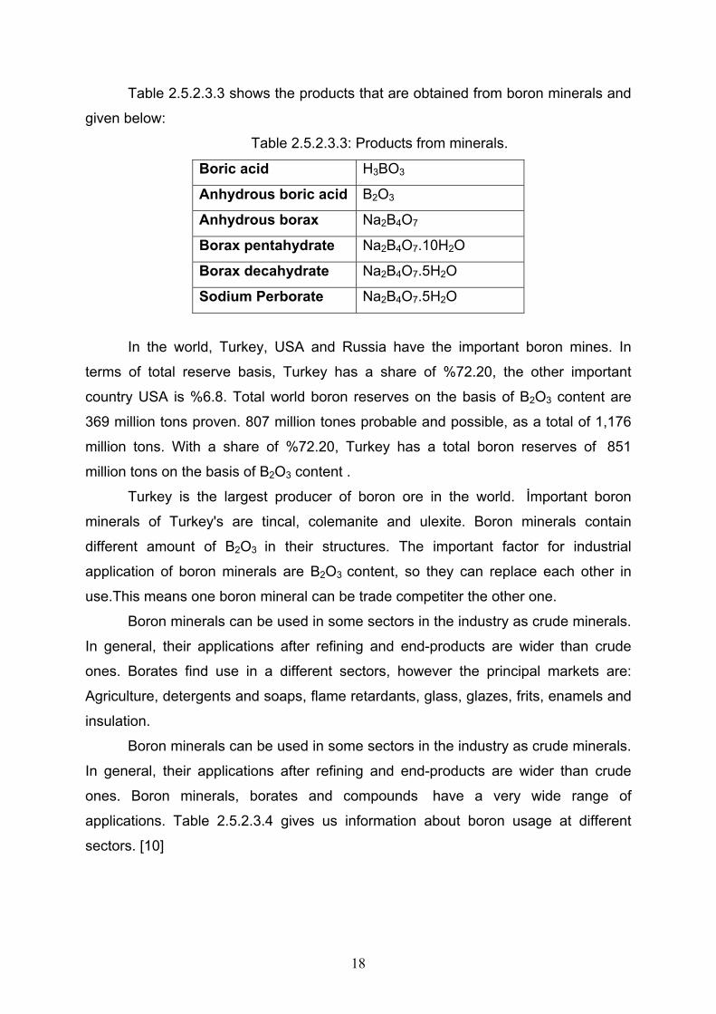
Table 2.5.2.3.3 shows the products that are obtained from boron minerals and
given below:
Table 2.5.2.3.3: Products from minerals.
Boric acid H3BO3
Anhydrous boric acid B2O3
Anhydrous borax Na2B4O7
Borax pentahydrate Na2B4O7.10H2O
Borax decahydrate Na2B4O7.5H2O
Sodium Perborate Na2B4O7.5H2O
In the world, Turkey, USA and Russia have the important boron mines. In
terms of total reserve basis, Turkey has a share of %72.20, the other important
country USA is %6.8. Total world boron reserves on the basis of B2O3 content are
369 million tons proven. 807 million tones probable and possible, as a total of 1,176
million tons. With a share of %72.20, Turkey has a total boron reserves of 851
million tons on the basis of B2O3 content .
Turkey is the largest producer of boron ore in the world. İmportant boron
minerals of Turkey's are tincal, colemanite and ulexite. Boron minerals contain
different amount of B2O3 in their structures. The important factor for industrial
application of boron minerals are B2O3 content, so they can replace each other in
use.This means one boron mineral can be trade competiter the other one.
Boron minerals can be used in some sectors in the industry as crude minerals.
In general, their applications after refining and end-products are wider than crude
ones. Borates find use in a different sectors, however the principal markets are:
Agriculture, detergents and soaps, flame retardants, glass, glazes, frits, enamels and
insulation.
Boron minerals can be used in some sectors in the industry as crude minerals.
In general, their applications after refining and end-products are wider than crude
ones. Boron minerals, borates and compounds have a very wide range of
applications. Table 2.5.2.3.4 gives us information about boron usage at different
sectors. [10]

19
Table 2.5.2.3.4: Application areas of boron and their affects.
Application Area Functions
Agriculture Essential micronutrient for all plant
Act as pH buffer
Soften the Washing water
Enhance the solubility of other ingredients
Act as a gentle but powerful bleaching agent
Detergents and Soaps
Anti-bacterial properties eliminate micro
organisms
Provide good fluxing properties Ceramic Glazes and Enamel Frits
Provide a good base for dissolving colouring
agents
Reduce the temperature at which fibres are
formed
Improve the durability of the glass fibres
Reduce the viscositry of the molten glass
Insulation Fibreglass
Increase the biosolubility of the glass fibres
Prevent and control the spread of bacteria
Inhibit corrosion
Timber Preservation
Act as flame retardant
Enhance the performance of alumina trihydrate Flame Retardants
Effective as flame retardants
Absorb thermal neutrons
Used to control nuclear reaction
Nuclear Power Stations
Used in nuclear shielding
Neutralize fatty acid
Act as emulsifiers in certain creams
Cosmetics and Medicine
Give mild antiseptic properties
Used as cover fluxes Metallurgy
Dissolve and remove un wanted metal oxides as
slag
Others(Glass,magnets, utomobile
airbags, photography, fuels…)

20
Boriding, or boronizing, is a thermo-chemical surface hardening process that
can be applied to a wide variety of ferrous, nonferrous, and cermet materials. The
process involves heating well-cleaned material in the range of 700 to 1000 °C (1300
to 1830 °F), preferably for 1 to 12 h, in contact with a boronaceous solid powder
(boronizing compound), paste, liquid, or gaseous medium. Other developments in
thermochemical boriding include gas boriding techniques such as plasma boriding
and fluidized bed boriding. There is a current trend toward the use of multi
component boriding.
During boriding, the diffusion and subsequent absorption of boron atoms into
the metallic lattice of the component surface form interstitial boron compounds. The
resulting layer may consist of either a single-phase boride or a polyphase boride
layer. The morphology as seen at Figure 2.5.2.3.1, growth, and phase composition of
the boride layer can be influenced by the alloying elements in the base material. The
microhardness of the borided layer also depends strongly on the composition and
structure of the boride layer and the composition of the base material are given at
table 2.5.2.3.5.
Table 2.5.2.3.5 : Melting point and microhardness of different boride phases formed
during boriding of different substrate materials with 100 g and 200 g load.

21
Figure 2.5.2.3.1:Effect of steel composition on the morphology and thickness of the
boride layer.
Advantages of boriding include:
• One basic advantage is that boride layers have extremely high hardness
values (between 1450 and 5000 HV) with high melting points of the
constituent phases.
• The hardness of boride layers produced on carbon steels is much greater
than that produced by any other conventional surface (hardening)
treatments
• The combination of a high surface hardness and a low surface coefficient
of friction of the borided layer also makes a significant contribution in
combating the main wear mechanisms: adhesion, tribooxidation, abrasion,
and surface fatigue. This fact has enabled the mold makers to substitute
easier-to-machine steels for the base metal and to stil obtain wear
resistance and antigalling properties superior to those of the original
material.
• Hardness of the boride layer can be retained at higher temperatures than,
for example, that of nitrided cases
• A wide variety of steels, including through-hardenable steels, are
compatible with the processes.
• Boriding, which can considerably enhance the corrosion-erosion resistance
of ferrous materials in nonoxidizing dilute acids and alkali media, is
increasingly used to this advantage in many industrial applications.

22
• Borided surfaces have moderate oxidation resistance (up to 850 °C, or
1550 °F) and are quite resistant to attack by molten metals.
• Borided parts have an increased fatigue life and service performance
under oxidizing and corrosive environments.
Disadvantages of boronizing treatments are:
• The techniques are inflexible and rather labor intensive, making the process
less cost effective than other thermochemical surface hardening treatments
such as gas carburizing and plasma nitriding. Both gas carburizing and
plasma nitriding have the advantage over boronizing because those two
processes are flexible systems, offer reduced operating and maintenance
costs, require shorter processing times, and are relatively easy to operate. It
is, therefore, suited to engineering components that need high hardness and
outstanding wear and corrosion resistance of the boride layers, and/or where
cheaper labor is available.
• The growth (that is, the increase in volume) resulting from boronizing is 5 to
25% of the layer thickness (for example, a 25 µm layer would have a growth of
1.25 to 6.25 µm); its magnitude depends on the base material composition but
remains consistent for a given combination of material and treatment cycle.
However, it can be predicted for a given part geometry and boronizing
treatment. For treatment of precision parts, where little stock removal is
permitted, an allowance of ~20 to 25% dimensional increase of the final boride
layer thickness must be provided.
• Partial removal of the boride layer for closer tolerance requirements is made
possible only by a subsequent diamond lapping because conventional
grinding causes fracture of the layer. Thus, precise boronizing is mostly
practiced for components with a large cross-sectional area.
• Boriding of most steels provides a marginal increase, if any, in the bending
fatigue endurance limit, although some improvement in the corrosion-fatigue
strength has been noticed. In general, the rolling contact fatigue properties of
borided alloy steel parts are very poor compared to carburized and nitrided
steels at high contact loads (2000 N, or 450 lbf). This is why boronizing

23
treatments of gears are limited to those screw designs where transverse
loading of gear teeth is minimized.
• There is frequently a need to harden and temper the tool after boriding which
requires a vacuum or inert atmosphere to preserve the integrity of the boride
layer.
Unlike carburizing treatment on ferrous materials, where there is a gradual
decrease in composition from the carbon-rich surface to the substrate, the boriding of
ferrous materials results in the formation of either a single-phase or double-phase
layer of borides with definite compositions. The single-phase boride layer consists of
Fe2B, while the double-phase layer consists of an outer dark-etching phase of FeB
and an inner bright-etching phase of Fe2B. The formation of either a single or double
phase depends on the availability of boron.
The formation of a single Fe2B phase (with a sawtooth morphology due to
preferred diffusion direction) is more desirable than a double-phase layer with FeB.
The boron-rich FeB phase is considered undesirable because FeB is more brittle
than the iron subboride Fe2B layer. Also, because FeB and Fe2B are formed under
tensile and compressive residual stresses, respectively, crack formation is often
observed at or in the neighborhood of the FeB/Fe2B interface of a double-phase
layer. These cracks may lead to flaking and spalling when a mechanical strain is
applied or even separation as seen at Figure 2.5.2.3.2 when a component is
undergoing a thermal and/or mechanical shock. Therefore, the boron-rich FeB phase
should be avoided or minimized in the boride layer.
Figure 2.5.2.3.2: Separation of two-phase boride layer on a low-carbon steel.

24
It has also been reported that the tribological properties depend on the
microstructure of the boride layer. The dual-phase FeB-Fe2B layers are not inferior to
those of monophase Fe2B layers, provided that the porous surface zone directly
beneath the surface is removed. Alternatively, a thinner layer is favored because of
less development of brittle and porous surface-zone formation and flaking.
Typical properties of the FeB phase are:
• Microhardness of about 19 to 21 GPa (2.7 × 10⁶ to 3.0 × 10⁶ psi)
• Modulus of elasticity of 590 GPa (85 × 106 psi)
• Density of 6.75 g/cm3 (0.244 lb/in.3)
• Thermal expansion coefficient of 23 ppm/°C (13 ppm/°F) between 200 and
600 °C (400 and 1100 °F)
• Composition with 16.23 wt% boron
• Orthorhombic crystal structure with 4 iron and 4 boron atoms per unit cell
• Lattice parameters: a = 4.053 Ǻ , b = 5.495Ǻ , and c = 2.946 Ǻ
The formation of single-phase Fe2B layers with a sawtooth morphology is
desirable in the boriding of ferrous materials. A single Fe2B phase can be obtained
from a double FeB-Fe2B phase by a subsequent vacuum or salt bath treatment for
several hours above 800 °C (1470 °F), which may be followed by oil quenching to
increase substrate properties.
Typical properties of Fe2B are:
• Microhardness of about 18 to 20 GPa (2.6 × 10⁶ to 2.9 × 10⁶ psi)
• Modulus of elasticity of 285 to 295 GPa (41 × 106 to 43 × 106 psi)
• Thermal expansion coefficient of 7.65 ppm/°C (4.25 ppm/°F) and 9.2
ppm/°C (5.1 ppm/°F) in the range of 200 to 600 °C (400 to 1100 °F) and
100 to 800 °C (200 to 1500 °F), respectively (Ref 6 and 17)
• Density of 7.43 g/cm3 (0.268 lb/in.3)
• Composition with 8.83 wt% boron
• Body-centered tetragonal structure with 12 atoms per unit cell
• Lattice parameters: a = 5.078 Ǻ and c = 4.249 Ǻ

25
There are six types of boriding process available in industry which are ;
1. Pack Boriding
2. Paste Boriding
3. Gas Boriding
4. Fludized Bed Boriding
5. Liquid (salt bath) Boriding
6. Plasma Boriding
2.5.2.3.1. Pack Boriding Pack boriding is the most widely used boriding process because of its relative
ease of handling, safety, and the possibility of changing the composition of the
powder mix, the need for limited equipment, and the resultant economic Savings. The
process involves packing the annealed, cleaned, smooth parts in a boriding powder
mixture contained in a 3 to 5 mm (0.1 to 0.2 in.) thick, heat-resistant steel box so that
surfaces to be borided are covered with an approximately 10 to 20 mm (0.4 to 0.8 in.)
thick layer. Many different boriding compounds have been used for pack boriding.
They include solid boron-yielding substances, diluents, and activators.
The common boron-yielding substances are boron carbide (B4C), ferroboron,
and amorphous boron; the last two have greater boron potential, provide a thicker
layer, and are more expensive than B4C. Silicon carbide (SiC) and alumina (Al2O3)
serve as diluents, and they do not take part in the reaction. However, SIC controls
the amount of boron and prevents caking of the boronizing agent. NaBF4, KBF4,
(NH4)3BF4, NH4Cl, Na2CO3, BaF2, and Na2B4O7 are the boriding activators. There are
special proprietary brands of boriding compounds, such as different grades of
Ekabor, available on the market that can be used with confidence.
Typical compositions of commercial solid boriding powder mixtures are:
• 5% B4C, 90% SiC, 5% KBF4
• 50% B4C, 45% SiC, 5% KBF4
• 85% B4C, 15% Na2CO3
• 95% B4C, 5% Na2B4O7

26
• 84% B4C, 16% Na2B4O7
• Amorphous boron (containing 95 to 97% B)
• 95% amorphous boron, 5% KBF4
The parts conforming to the shape of the container are packed at Figure
2.5.2.3.1.1, covered with a lid, which rests inside the container and is weighted with
an iron slug or stone to ensure an even trickling of the boriding agent during the
boriding treatment. It is then heated to the boriding temperature in an electrically
heated box or pit furnace with open or covered heating coils or a muffle furnace for a
specified time. The container should not exceed 60% of the furnace chamber volume.
In principle, boriding should be accomplished in such a way that high internal
stresses are relieved, which in turn, eliminates cracks or spalling. With the packing
process, the powder may be reused by blending with 20 to 50 wt% of fresh powder
mixture. In this case, the powder should be discarded after 5 or 6 cycles.
Figure 2.5.2.3.1.1: Diagram of the packing of a single geometrical part in a pack
boriding box.

27
The thickness of the boride layer depends on the substrate material being
processed, boron potential of the boronizing compound , boronizing temperature, and
time as seen at Figure 2.5.2.3.1.2. In ferrous materials, the heating rate especially
between 700 °C (1300 °F) and the boriding temperature (800 to 1000 °C, or 1470 to
1830 °F) should be high in order to minimize the formation of FeB.
Figure 2.5.2.3.1.2: Effect of pack boriding temperature and time on the boride layer
thickness in a low-carbon steel.
2.5.2.3.2. Paste Boriding Paste boriding is used commercially when pack boronizing is difficult, more
expensive, or time consuming. In this process, a paste of 45% B4C (grain size 200 to
240 µm) and 55% cryolite (Na3AlF6, flux additive), or conventional boronizing powder
mixture (B4C-SiC-KBF4) in a good binding agent (such as nitrocellulose dissolved in
butyl acetate, aqueous solution of methyl cellulose, or hydrolyzed ethyl silicate) is
repeatedly applied at intervals over the entire or selected portion of parts until a layer
about 1 to 2 mm (0.04 to 0.08 in.) thick is obtained. Subsequently, the ferrous

28
materials are heated at 900 °C for 4 h inductively or in a conventional furnace to 800
to 1000 °C for 5 h. In this process, a protective atmosphere (for example, argon,
cracked NH3, or N2) is necessary. A layer in excess of 50 µm thickness may be
obtained after inductively or resistively heating to 1000 °C for 20 min. This process is
of special interest for large components or for those requiring partial boriding.
2.5.2.3.3. Gas Boriding Gas boriding may be accomplished with:
• Diborane (B2H6)-H2 mixture
• Boron halide-H2/or (75:25 N2-H2) gas mixture
• Organic boron compounds such as (CH3)3B and (C2H5)3B.
Boronizing with B2H6-H2 mixture is not commercially viable due to the high
toxic and explosive nature of diborane. When organic boron compounds are used,
carbide and boride layers form simultaneously. Because BBr3 is expensive and is
difficult to handle (with violent reactions with water), and because BF3 requires high
reduction temperature (due to its greater stability) and produces HF fumes, BCl3
remains the attractive choice for gas boriding.
When parts are gas borided in a dilute (1:15) BCl3-H2 gas mixture at a
temperature of 700 to 950 °C and a pressure up to 67 kPa (0.67 bar), a boride layer
120 to 150 µm thick is reported to be produced at 920 °C (1690 °F) in 2 h. Recent
work has suggested the use of 75:25 N2-H2 gas mixture instead of H2 gas for its beter
performance because of the production of boride layers with minimum FeB content.
The latter phase can be easily eliminated during the subsequent diffusion treatment
before hardening. This process can be applied to titanium and its alloys as well.

29
2.5.2.3.4. Fludized Bed Boriding A recent innovation is boriding in fluidized beds which is shown at Figure
2.5.2.3.4.1, which involves bed material of coarse-grained silicon carbide particles, a
special boriding powder such as Ekabor WB, and an oxygen-free gas such as N2-H2
mixture. When electricity is used as the heat source, the bed serves as a faster heat-
transfer medium. This is usually equipped with quench and tempering furnaces.
Figure 2.5.2.3.4.1: Diagram of a fluidized bed for boriding.
This process offers such advantages as:
• High rates of heating and flow, as well as direct withdrawal of the parts,
provide shorter operating cycle times (that is, rapid boronizing).
• Temperature uniformity with low capital cost and flexibility is ensured.
• A fluidized furnace is very tight because of upward pressure of the gas.
• This process produces reproducibility, close tolerances, and a very uniform
finish on mass-produced parts.

30
• This process can be adaptable to continuous production and can lend itself to
automation as the parts are charged and withdrawn intermittently.
• Quenching (and subsequent tempering) of the parts directly after this
treatment is possible.
• Low operating cost (due to reduced processing time and energy consumption)
for mass production of boronized parts.
An important disadvantage lies in the continuous flushing of the boriding agent
within the retort by the inert gas. The exhaust gases containing enriched fluorine
compounds must be cleaned absolutely, for example, in an absorber filled with dry
CaCO3 chips to avoid environmental problems.
2.5.2.3.5. Liquid (salt bath) Boriding Liquid boriding is grouped into two types;
1. Electroless
2. Electrolytic
These processes have several disadvantages:
• Removal of excess salt and unreacted boron is essential after the
treatment; this step may prove to be expensive and time consuming.
• To achieve boronizing reproducibility, bath viscosity is not allowed to
increase. This is done by recharging with salt, which involves high
maintenance costs.
• In some situations protection from corrosive fumes may be required.
2.5.2.3.5.1. Electroless Liquid Boriding Electroless salt bath boriding of ferrous materials is carried out in a borax-
based melt at about 900 to 950 °C (1650 to 1750 °F), to which about 30 wt% B4C is
added. The boronizing action can be further improved by replacing up to 20 wt% B4C
with ferroaluminum because it is a more effective reductant. However, superior

31
results have been found by using a salt bath mixture containing 55% borax, 40 to
50% ferroboron, and 4 to 5% ferroaluminum. It has also been shown that 75:25
KBF4-KF salt bath can be used at temperature below 670 °C (1240 °F) for boronizing
nickel alloys, and at higher temperatures for ferrous alloys, to develop the desired
boride layer thickness.
2.5.2.3.5.2. Electrolytic Liquid Boriding
In this process, the ferrous part acting as the cathode and a graphite anode
are immersed in the electrolytic molten borax at 940 °C (1720 °F) for 4 h using a
current density of about 0.15 A/cm2 . The parts are then air cooled. In general, the
parts are rotated during the treatment to obtain a uniform layer. A high current density
produces a thin coating on low-alloy steels in a short time. For high-alloy steels of
greater thickness, lower current densities are required for a longer time.
In the fused state tetraborate decomposes into boric acid and nascent oxygen.
B4O7 + 2e = 2B2O3 + O Eq. 2.5.2.3.5.2.1
Simultaneously, sodium ions, after being neutralized in the vicinity of cathode,
react with boric acid to liberate boron.
6 Na + B2O3 = 3 Na2O + 2B Eq. 2.5.2.3.5.2.2
In this manner, a high boriding potential is established near the cathode
region. Other satisfactory electrolytic salt bath compositions include:
• KBF4-LiF-NaF-KF mixture for parts to be treated at 600 to 900 °C (1100 to
1650 °F).
• 20KF-30NaF-50LiF-0.7BF2 mixture (by mole %) at 800 to 900 °C (1470 to
1650 °F) in 90N2-10H2 atmosphere
• 9:1 (KF-LiF)-KBF4 mixture under argon atmosphere.
• KBF4-NaCl mixture at 650 °C (1200 °F).
• 90(30LiF + 70KF)-10KBF4 mixture at 700 to 850 °C (1300 to 1560 °F)
• 80Na2B4O7-20NaCl at 800 to 900 °C (1470 to 1650 °F).

32
2.5.2.3.6. Plasma Boriding Both mixtures of B2H6-H2 and BCl3-H2-Ar may be used successfully in plasma
boronizing. However, the former gas mixture can be applied to produce boride layer
on various steels at relatively low temperatures such as 600 °C (1100 °F), which is
impossible with a pack or liquid boronizing process. It has been claimed that plasma
boriding in a mixture of BCl3-H2-Ar gases shows good features such as better control
of BCl3 concentration, reduction of the discharge voltage, and higher microhardness
of the boride films. Figure 2.5.2.3.6.1 shows a schematic layout of a plasma boriding
facility.
Figure 2.5.2.3.6.1: Layout of plasma boronizing facility.
The dual-phase layer is characterized by visible porosity, occasionally
associated with a black boron deposit. This porosity, however, can be minimized by
increasing the BCl3 concentration. Boride layers up to 200 µm in thickness can be
produced in steels after 6 h treatment at a temperature of 700 to 850 °C (1300 to
1560 °F) and a pressure of 270 to 800 Pa (2 to 6 torr).

33
Advantages of this process are:
• Control of composition and depth of the borided layer
• Increased boron potential compared to conventional pack boronizing
• Finer plasma-treated boride layers
• Reduction in temperature and duration of treatment
• Elimination of high-temperature furnaces and their accessories
• Savings in energy and gas consumption
The only disadvantage of the process is the extreme toxicity of the
atmosphere employed. As a result, this process has not gained commercial
acceptance. To avoid the above shortcoming, boriding from paste (containing a
mixture of 60% amorphous boron and 40% liquid borax) in a glow discharge at the
impregnating temperature has been recently developed, which is found to greatly
increase the ormation of the surface boride layer.[11]

34
PART 3. SCOPE OF EXPERIMENTAL WORK This part consists of four section which are ;
1. Workpiece Preperation
2. Boriding Agent Preperation
3. Heat Treatment (Boriding)
4. Measurements After Boriding
3.1. WORKPIECE PREPERATION The steel specimen was obtained from Asil Çelik San. Ve Tic. A.Ş. and the
chemical composition is given below at table 3.1.1.
Table 3.1.1: Chemical Analysis of 1040 Plain Carbon Steel.
C % Si % Mn % P % S % Fe %
0.41 0.23 0.74 0.008 0.002 Retained
The specimens are prepared to use in the boriding process. For different
temperature treatment totally six specimen are used. Their dimensions are given
below at Figure 3.1.1.
Figure 3.1.1: Dimensions of test specimen
Before boriding process surface treatments are applied to obtain a smooth
surface. Then the metallographic processes which are cutting, grinding, polishing and
etching are applied to take photograps of microstructures. For the metallographic
processes the devices used are given below table 3.1.2.
40 mm
15 mm
4 mm
Ǿ 5 mm

35
Table 3.1.2: Used devices during the metallographic processes.
Device’s name Function
Struers Discotom-5 Cutting
Struers Pronto Pres-10 Bakalite Coating
Struers Labopol-21 Grinding
Struers Dap-7 Diamond Polishing
Olympus B061 Optical Microscopy Photographing
3.2. BORIDING AGENT PREPERATION
During the liquid boroding process we use water free borax and Ferro-Silicon.
The compositions of boridig agent are 70% wt Borax and 30% wt Fe-Si. To obtain
water free borax we use Borax pentahydrate (Na2B4O7.10H2O). The crystalline water
of Borax pentahydrate should be removed as much as possible against overflow of
liquid mixture during the boriding heat treatment process. Because the borax can
damage the refractory lining of the inerside of the furnace. For that process the
temperature changes and time distributions are given at table 3.2.1
Table 3.2.1: Temperature and Time distribution of borax pentahydrate.
Temperature Interval (˚C) Time (min.)
20 -150 20
150 – 150 60
150 – 250 20
250 – 250 60
250 – 600 60
600 – 600 120
600 - 20 60
After calcination we take a TGA analysis for our water free borax. The graph
has formed as seen at Figure 3.2.1. It tells us there is a bit crystalline water inside of
borax. That can be happen because of the trapping air moisture during handling.

36
Figure 3.2.1: TGA vs Temperature of borax.
Other part of the boriding agent is Fe-Si. The preperation of ferro silicon
consists of only crushing. Because of the coarse particles we need to get fine ferro
silicon. So the powder mixture can be more homogeneous when we use fine
particles. The devices for this part are given at table 3.2.2. The furnace which is
shown at Figure 3.2.2, is also used during the boriding process.
Table 3.2.2: Used devices during the boriding agent preperation.
Device’s name Function
Nabertherm Supertherm HT 40/17 Heating
Fritsch Jaw Crusher Crushing
Precisa XB 320 Max. Weighting
Netzsch STA 409 CD DTA/TGA

37
Figure 3.2.2: Photograph of Nabertherm furnace.
3.3. HEAT TREATMENT (BORIDING)
The prepared powder mixture has poured into the stainless steel box which is
shown at Figure 3.3.1 rather than graphite laddle. First boriding agent is put in then
the two specimen is put and finally boriding agent is put again. We use two specimen
for each test because of precaution. All the system is set in the furnace and the
boriding procedure is started. The heating time and temperatures are given at table
3.3.1.
Table 3.3.1: Temperature and Time distribution of boriding.
# of Boriding Temperature Interval (˚C) Time (hour)
20 -850 1 1
850 – 850 6
20 -900 1.25 2
900 – 900 6
20 -950 1.5 3
950 – 950 6

38
Figure 3.3.1: Dimensions of the Stainless steel box.
After heat treatment about six hours the specimen should be taken out
stainless steel box because solidification of liquid borax is rapid and the viscosity of
the liquid increases with dicreasing temperature. Then the specimens are normalized
in air.
3.4. MEASUREMENTS AFTER BORIDING After boriding the specimens are applied metallographic processes to take
microstructural photos again. Then they are examined by SEM. Finally hardness
values are obtained for all specimens with the Instron Hardness device which is
shown at Figure 3.4.1 and the equipments which are used at that step are given table
3.4.1.
Table 3.4.1: Used devices during the measurements after boriding.
Device’s name Function
Instron Wolpert Testor 930/250 Hardness
Joel Low Vacuum SEM
70 mm
70 mm
70 mm

39
Figure 3.4.1: Instron Hardness Measurement Device.

40
PART 4. RESULTS During the experimental steps we obtained some results which we will talk in
that part. The steps should be as same as the part 3. The metallographic
photographs before boriding and after boriding are seen at Figure 4.1, 4.2, 4.3.
Figure 4.1: Microstructures before boriding process. a) 200x, b)500x, c)800x.
41
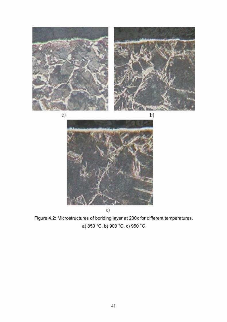
Figure 4.2: Microstructures of boriding layer at 200x for different temperatures.
a) 850 °C, b) 900 °C, c) 950 °C

42
Figure 4.3: Microstructures of boriding layer at 800x for different temperatures.
a) 850 °C, b) 900 °C, c) 950 °C.

43
The next process after metallography SEM is used to get photos of crystalline
structure of boriding layer. Figure 4.4. shows the SEM photos and table 4.1. gives the
chemical analysis of the boriding layer.
Figure 4.4: Crystalline structures of boring layer for different temperatures.
a) 10000x at 850°C, b) 5000x at 900°C, c) 5000x at 950°C.

44
Table 4.1: Chemical analysis of boriding layer at 900°C and 950°C.
Boriding Temperature B% C% Na% Fe% Total%
900°C 24.21 52.63 5.83 17.34 100.00
950°C 28.34 58.16 7.12 6.38 100.00
Final part of the measurements are hardness tests at above and below of
borided layer and surface of initial state. Micro hardness values are obtained with
using Instron hardness device as I told before. The dwell time for testing is 10
seconds and testing load is 30 kg. The results are given at table 4.2 and figure 4.5
shows the distributon.
Table 4.2: Data obtained from the measurements.
Initial surface Below the boriding layer Borided Layer
20 °C 850 °C 900 °C 950 °C 850 °C 900 °C 950 °C
201 HV 222 HV 241 HV 242 HV 228 HV 251 HV 264 HV
205 HV 223 HV 244 HV 248 HV 230 HV 253 HV 265 HV
205 HV 223 HV 244 HV 249 HV 247 HV 255 HV 266 HV
206 HV 225 HV 246 HV 251 HV 249 HV 258 HV 270 HV
207 HV 225 HV 249 HV 254 HV 258 HV 261 HV 275 HV
Avg:204 Avg:223 Avg:244 Avg:248.8 Avg:242,4 Avg:255,6 Avg:268

45
200
210
220
230
240
250
260
270
280
1 2 3
# of Test
Har
dnes
s (H
V)
850900950
Figure 4.5: The distribution of results according to the temperature and process
condition.
Initial Surface
Below Boriding Layer
Borided Layer
46
PART 5. DISCUSSIONS AND EVALUATIONS
In this part we will discuss about the results which we obtained and mentioned
at part 4. Before boriding process we have took photos to understand the specimen’s
microstructure. As seen at Figure 4.1 the microstructure consist of mainly ferrite and
pearlite. At 800x the pearlite lamellas are easily seen near the ferrite matrix.
After boriding process we can observe the boriding layer and the diffusion
zones as shown at Figure 4.2 and 4.3. Because of the normalizing in air after the
heat treatment, the microstructure becames ferrite matrix and pearlite lamellas.
Although we increase the temperature at the austenite region that does not affect the
microstructure because of the normilizing process. At Figure 4.3 the microstructures
and the boriding layer are shown obviously. Boriding layer consists of two regions
which are FeB and Fe2B. The upper and the brighter part is the FeB layer. The
darker part which is in sawtooth shape is the Fe2B. As I mentioned before at part
2.5.2.3. Fe2B layer is more desirable than the FeB. In our experiment The process
temperature like 850°C and 900°C affects the formation of the layer characteristics.
Another reasen we an talk about the formation of FeB layer can be the boriding agent
source during the experiment. The minority of the source can be affect that result.
The Figure 4.4. shows us the boriding layers at greater magnifications. The
layer thickness directly affects the hardness because of the diffusion rules. The data
are given at table 4.2. According to this table the micro hardness values increases
with increasing temperature. The initial specimen’s hardness values are the lowest
ones. Below the boriding layer the hardness values takes second because this part is
also heat treated. That means the microstructure may be same as initials state but
the hardness increases because of the removal of the residual stresses.
The plot is constructed with using table 4.2. and there is an obvious increase
with respect to increasing temperature. Hardness values of boriding layer and the
place just below the boriding layer varies.
47
According to the later investigations about boriding process about the wear
resistance gives interesting results. During the compressional forcess the boriding
layer preserves its form but the longitudional loadings such as cutting of the cross
sectional area that damages the boriding layer.
We can clearly say that the boriding process can be easily applied for
industrial applications except the conditions which I talk above. One disadvantage of
liquid boriding is the difficulty of handling during the removal from the furnace.
Because in liquid state it can be easily shaken and splashed on to the researcher.

48
PART 6. REFERENCES
1. Şaduman Şen, Cuma Bindal, “The Wear Behaviour of Borided AISI 4140
Steel” ,10th Int metallurgy and Materials Congress, P. 793, 2000.
2. William D.Callister,Jr, “Materials Science and Engineering”, 6th Edition, Wiley
Incorporation, Dislocations and strengthening mechanisms, pp 174-180, New
Jersey, 2003.
3. Wikipedia entry on Solid Solution Strengthening, website;
http://en.wikipedia.org/wiki/Solid_solution_strengthening
4. Wikipedia entry on Precipitation Hardening, website;
http://en.wikipedia.org/wiki/Precipitation_strengthening
5. Kay-to-steel entry on Surface Hardenings on Steels, website;
http://www.key-to-steel.com/Articles/Art113.htm
6. Pat L. Mangonon, “The Principles of Materials Selection For Engineering
Design”, 1st Edition, Prentice-Hall Incorporation, Thermal Processes, pp 134-
139, 223-227, 331-332, 374-380, New Jersey, 1999.
7. Efunda entry on Hardening Heat Treatment Processes, website;
http://www.efunda.com/processes/heat_treat/hardening/selective.cfm
8. Kay-to-steel entry on Carburizing, website;
http://www.key-to-steel.com/Articles/Art114.htm
9. Kay-to-steel entry on Nitriding, website;
http://www.key-to-steel.com/Articles/Art117.htm
10. Etimaden entry on Properties of Boron, website;
http://www.etimaden.gov.tr
11. “ASM Handbook Volume 4 Heat Treatment”, 9th Edition, The Materials
Information Company, Boriding of Steels, pp 978-984, 988-994, USA, 1991.