bosch ip video data security guidebook educational paper is written to assist integrators to harden...
TRANSCRIPT

3 February 2016
Bosch IP Video and Data Security Guidebook
Bosch Security Systems | Video Systems
How to improve Data Security What needs to be considered to safeguard video data

2 | Bosch Security Systems | Video Systems
©2016 Bosch Security Systems PN | 01 | 2015.02
Table of contents
Table of contents .................................................................................................................................................................... 2
Introduction ............................................................................................................................................................................. 3
Bosch IP video devices .......................................................................................................................................................... 3
Assigning IP addresses .......................................................................................................................................................... 4
Managing DHCP: ................................................................................................................................................................ 6
User accounts and passwords ............................................................................................................................................... 7
Applying passwords ............................................................................................................................................................ 7
Device web page: ............................................................................................................................................................ 8
Configuration Manager: ................................................................................................................................................... 9
DIVAR IP 2000 / 5000: .................................................................................................................................................. 10
Bosch Video Management System (BVMS) and DIVAR IP 3000 / 7000: ...................................................................... 11
Hardening device access ..................................................................................................................................................... 13
General network port usage and video transmission: ....................................................................................................... 13
HTTP, HTTPS, and video port usage: ........................................................................................................................... 14
Video software and port selection: ................................................................................................................................ 15
Telnet Access: ............................................................................................................................................................... 16
Cloud-based Services: .................................................................................................................................................. 17
RTSP (Real Time Streaming Protocol): ......................................................................................................................... 18
UPnP (Universal Plug and Play): ................................................................................................................................... 19
Multicasting: .................................................................................................................................................................. 20
IPv4 filtering:.................................................................................................................................................................. 21
Secure time basis: ......................................................................................................................................................... 22
802.1x protected networks: ........................................................................................................................................... 23
Extensible Authentication Protocol - Transport Layer Security ...................................................................................... 23
Creating trust with certificates .............................................................................................................................................. 24
Secured in a safe .............................................................................................................................................................. 24
TLS/SSL certificates: ..................................................................................................................................................... 25
Device web page: .......................................................................................................................................................... 25
Configuration Manager: ................................................................................................................................................. 26
Video Authentication ............................................................................................................................................................. 27
Authors ................................................................................................................................................................................. 28

3 | Bosch Security Systems | Video Systems
©2016 Bosch Security Systems PN | 01 | 2015.02
Introduction
While every organization in today’s environment may have cyber security procedures and policies in place,
standards may vary from organization to organization based on many factors such as size, region, and
industry.
In February 2014, The National Institute of Standards and Technology (NIST) introduced the Cyber Security
Framework. This framework is based on Executive Order 13636 and was created utilizing existing standards,
guidelines, and best practices. It is specifically designed to reduce cyber risks to critical infrastructures and
their network attached devices and data. This framework is designed to help organizations understand both
external and internal cyber security risks and is applicable to any size organization categorized from Tier 1
(Partial) to Tier 4 (Adaptive).
This educational paper is written to assist integrators to harden Bosch IP video products to better adhere to
their customer’s existing network security policies and procedures.
This guide will cover:
Critical information on the features and fundamentals of Bosch IP video devices
Specific features that can be modified or disabled
Specific features that can be activated and utilized
Best practices as they pertain to video systems and security
This guide will primarily focus on utilizing Bosch Configuration Manager to perform the configurations
discussed. In most cases all configurations can be performed utilizing Bosch Video Management System
Configuration Client, Bosch Configuration Manager, and the built in web interface of a video device.
Bosch IP video devices
IP video products are becoming commonplace in today’s network environment, and as with any IP device
placed on a network, IT administrators and security managers have a right to know the full extent of a device’s
feature set and capabilities.
When dealing with Bosch IP video devices your first line of protection are the devices themselves. Bosch
encoders and cameras are manufactured in a controlled and secure environment that is continually audited.
Devices can only be written to via a valid firmware upload, which is specific to hardware series and chipset.
Most Bosch IP video devices come with an onboard security chip that provides functionality similar to crypto
SmartCards and the so called “Trusted Platform Module”, or short TPM. This chip acts like a safe for critical
data, protecting certificates, keys, licenses, etc. against unauthorized access even when the camera is
physically opened to gain access.
Bosch IP video devices have been subjected to more than thirty thousand (30,000) vulnerability and
penetration tests performed by independent security vendors. Thus far, there have been no successful
cyberattacks on a properly secured device.

4 | Bosch Security Systems | Video Systems
©2016 Bosch Security Systems PN | 01 | 2015.02
Assigning IP addresses
All Bosch IP video devices currently come in a factory default state ready to accept a DHCP IP address. If no
DHCP server is available in the active network on which a device is deployed, the device will automatically
apply the default IP address 192.168.0.1. There are several tools that can be used to perform IP Address
assignment to Bosch IP video devices, including:
IP Helper
Bosch Configuration Manager
Bosch Video Management System Configuration Client
Bosch Video Management System Configuration Wizard
All software tools provide the option of assigning a single static
IPv4 address, as well as a range of IPv4 addresses to multiple
devices simultaneously. This includes subnet mask and default
gateway addressing.
All IPv4 addresses and subnet mask values need to be entered
in the so-called “dot-decimal notation”.
Subnetting is the act of borrowing bits from the
host portion of an IP address in order to break a
large network into several smaller networks. The
more bits you borrow, the more networks you
can create, but each network will support fewer
host addresses.
Since 1993, the Internet Engineering Task Force (IETF) introduced a new concept of allocating IPv4 address
blocks in a more flexible way than used in the former “classful network” addressing architecture. The new
method is called “Classless Inter-Domain Routing” (CIDR) and also used with IPv6 addresses.
Example: Bosch Configuration Manager
Data security hint no. 1
One of the first steps in limiting the possibilities of internal cyberattacks on a network,
executed by unauthorized locally attached network devices, is to limit available unused
IP addresses. This is done by using IPAM, or IP Address Management, in conjunction
with subnetting the IP address range that will be used.

5 | Bosch Security Systems | Video Systems
©2016 Bosch Security Systems PN | 01 | 2015.02
IPv4 classful networks are designated as Classes A, B and C, with 8, 16 and 24 network number bits
respectively, and Class D which is used for multicast addressing.
For larger networks the next bigger network Class B might be needed, or an appropriate CIDR block defined.
Taking into account the calculated number of 342 IP addresses, we at minimum need a B Class IP address
scheme to accommodate that many IP addresses. Using the default B Class subnet mask of 255.255.0.0
allows for 65,534 available IP addresses to be used within the network.
Alternatively, the network can be planned using a CIDR block with 23 bits used as prefix, providing an address
space of 512 addresses respectively 510 hosts.
By breaking a large network into smaller pieces, by simply subnetting, or specifying a CIDR block, you can
reduce this risk.
Example:
Prior to deploying your video security network, you perform a simple calculation of how many IP devices
will be needed on the network, to include room for future growth:
20 Video Workstations
1 Central Server
1 VRM Server
15 iSCSI Storage Arrays
305 IP cameras
Total = 342 IP addresses needed
Example:
For an easy to understand example, we will use a C Class address scenario. The default subnet mask of
a C Class address is 255.255.255.0. Technically, no subnetting has been done to this mask, so the
entire last octet is available for valid host addressing. As we borrow bits from the host address, we have
the following possible mask options in the last octet:
.128, .192, .224, .240, .248, and .252.
If utilizing the 255.255.255.240 subnet mask (4 bits) we are creating 16 smaller networks that support 14
host addresses per subnet.
Subnet ID 0:
host address range 192.168.1.1 to 192.168.1.14. Broadcast address 192.168.1.15
Subnet ID 16:
host address range 192.168.1.17 to 192.168.1.30. Broadcast address 192.168.1.31
Subnet IDs: 32, 64, 96, etc.

6 | Bosch Security Systems | Video Systems
©2016 Bosch Security Systems PN | 01 | 2015.02
Managing DHCP:
IPAM can utilize DHCP as a powerful tool in the control and
usage of IP addresses in your environment. DHCP can be
configured to utilize a specific scope of IP addresses. It can
also be configured to exclude a range of addresses as well.
If utilizing DHCP, it would be best, when deploying video
devices, to configure non-expiring address reservations
based on the MAC address of each device.
Example:
Default Subnetted
IP address range 172.16.0.0 - 172.16.255.255 172.16.8.0 - 172.16.9.255
Subnet mask 255.255.0.0 255.255.254.0
CIDR notation 172.16.0.0/16 172.16.8.0/23
Number of subnets 1 128
Number of hosts 65,534 510
Excess addresses 65,192 168
Data security hint no. 2
Even before using IP Address Management to track the usage of IP addresses, a network
management best practice is to limit access to the network through port security on edge
switches, e.g. only a specific MAC address can access through a specific port.
7 | Bosch Security Systems | Video Systems
©2016 Bosch Security Systems PN | 01 | 2015.02
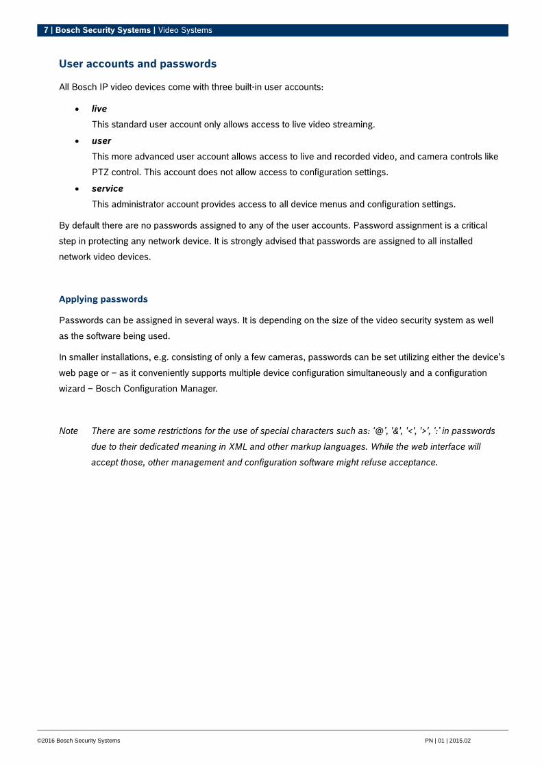
User accounts and passwords
All Bosch IP video devices come with three built-in user accounts:
live
This standard user account only allows access to live video streaming.
user
This more advanced user account allows access to live and recorded video, and camera controls like
PTZ control. This account does not allow access to configuration settings.
service
This administrator account provides access to all device menus and configuration settings.
By default there are no passwords assigned to any of the user accounts. Password assignment is a critical
step in protecting any network device. It is strongly advised that passwords are assigned to all installed
network video devices.
Applying passwords
Passwords can be assigned in several ways. It is depending on the size of the video security system as well
as the software being used.
In smaller installations, e.g. consisting of only a few cameras, passwords can be set utilizing either the device’s
web page or – as it conveniently supports multiple device configuration simultaneously and a configuration
wizard – Bosch Configuration Manager.
Note There are some restrictions for the use of special characters such as: ‘@’, '&', '<', '>', ‘:’ in passwords
due to their dedicated meaning in XML and other markup languages. While the web interface will
accept those, other management and configuration software might refuse acceptance.
8 | Bosch Security Systems | Video Systems
©2016 Bosch Security Systems PN | 01 | 2015.02
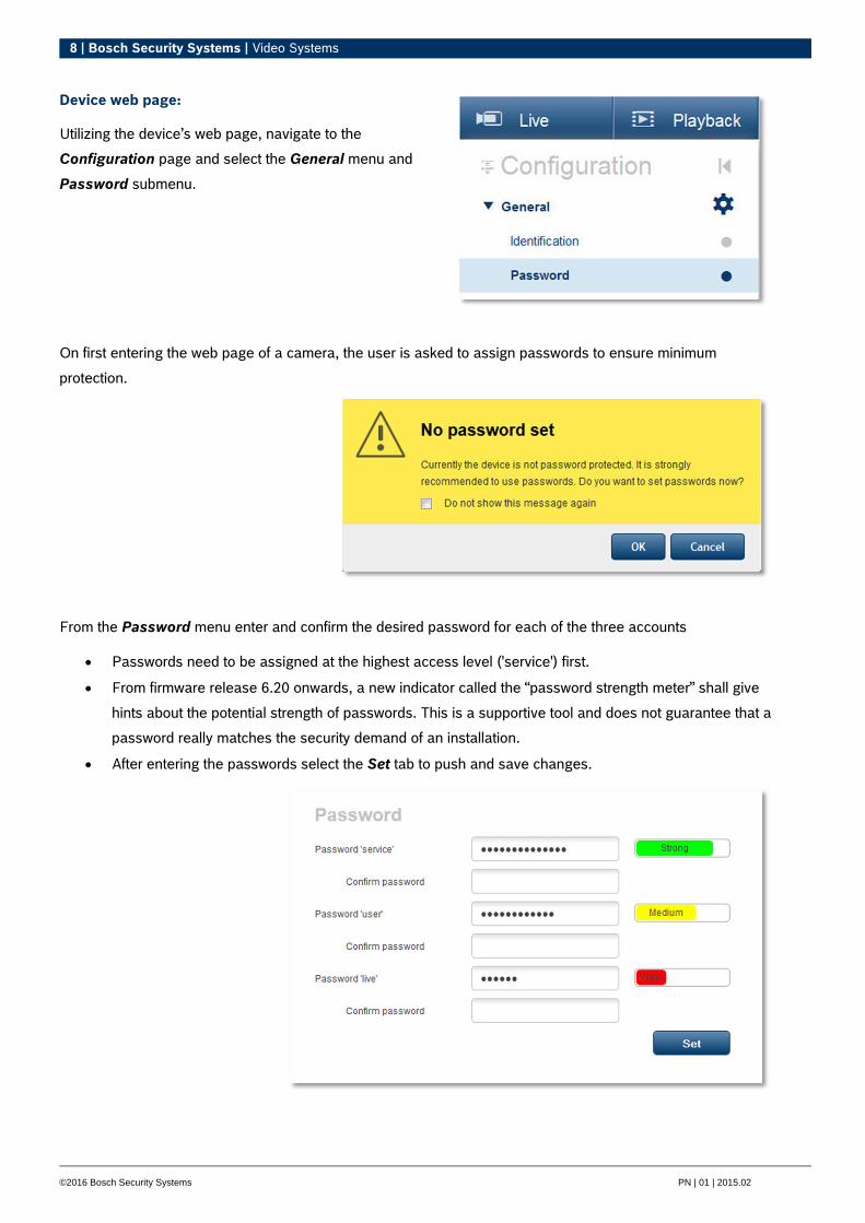
Device web page:
Utilizing the device’s web page, navigate to the
Configuration page and select the General menu and
Password submenu.
On first entering the web page of a camera, the user is asked to assign passwords to ensure minimum
protection.
From the Password menu enter and confirm the desired password for each of the three accounts
Passwords need to be assigned at the highest access level ('service') first.
From firmware release 6.20 onwards, a new indicator called the “password strength meter” shall give
hints about the potential strength of passwords. This is a supportive tool and does not guarantee that a
password really matches the security demand of an installation.
After entering the passwords select the Set tab to push and save changes.
9 | Bosch Security Systems | Video Systems
©2016 Bosch Security Systems PN | 01 | 2015.02
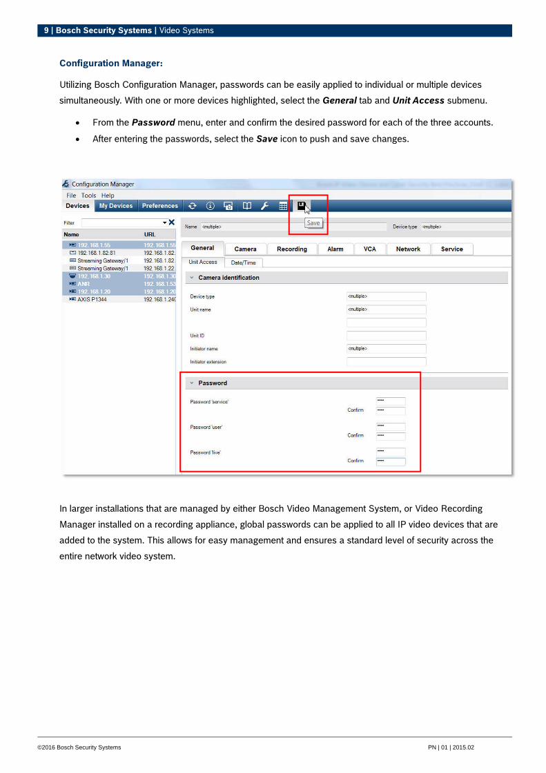
Configuration Manager:
Utilizing Bosch Configuration Manager, passwords can be easily applied to individual or multiple devices
simultaneously. With one or more devices highlighted, select the General tab and Unit Access submenu.
From the Password menu, enter and confirm the desired password for each of the three accounts.
After entering the passwords, select the Save icon to push and save changes.
In larger installations that are managed by either Bosch Video Management System, or Video Recording
Manager installed on a recording appliance, global passwords can be applied to all IP video devices that are
added to the system. This allows for easy management and ensures a standard level of security across the
entire network video system.

10 | Bosch Security Systems | Video Systems
©2016 Bosch Security Systems PN | 01 | 2015.02
DIVAR IP 2000 / 5000:
The DIVAR IP recording appliance is equipped with an easy to use Configuration wizard. The assignment of
a system-wide administrator password is mandatory when configuring the system. This password is assigned
to the service account of all IP video cameras added to the system. The ability to add a user account
password is also provided in the wizard, but implementation is not mandatory.
The password strength indicator is using a similar algorithm as when using the web page.

11 | Bosch Security Systems | Video Systems
©2016 Bosch Security Systems PN | 01 | 2015.02
Bosch Video Management System (BVMS) and DIVAR IP 3000 / 7000:
BVMS version 5.0 and higher provides the ability to implement global passwords on all devices in a video
system of up to 2000 IP cameras. This feature can be accessed either via the BVMS configuration wizard
when working with DIVAR IP 3000 or 7000 recording appliances, or though BVMS configuration client on any
system.
To access the global passwords menu in BVMS configuration client:
Select the Hardware menu at the top of the application.
Select the Protect Devices with Default Password… sub menu.
Enter a Global default password and select Enforce password protection on activation.
After saving and activating system changes, the password entered will be applied to the live, user, and
service accounts of all devices, including the administrator account of Video Recording Manager.
Note If the devices already have existing passwords set in any of the accounts, they will not be overwritten.
E.g. if password is set for service but not for live and user, global password will only be configured for
live and user accounts.
12 | Bosch Security Systems | Video Systems
©2016 Bosch Security Systems PN | 01 | 2015.02
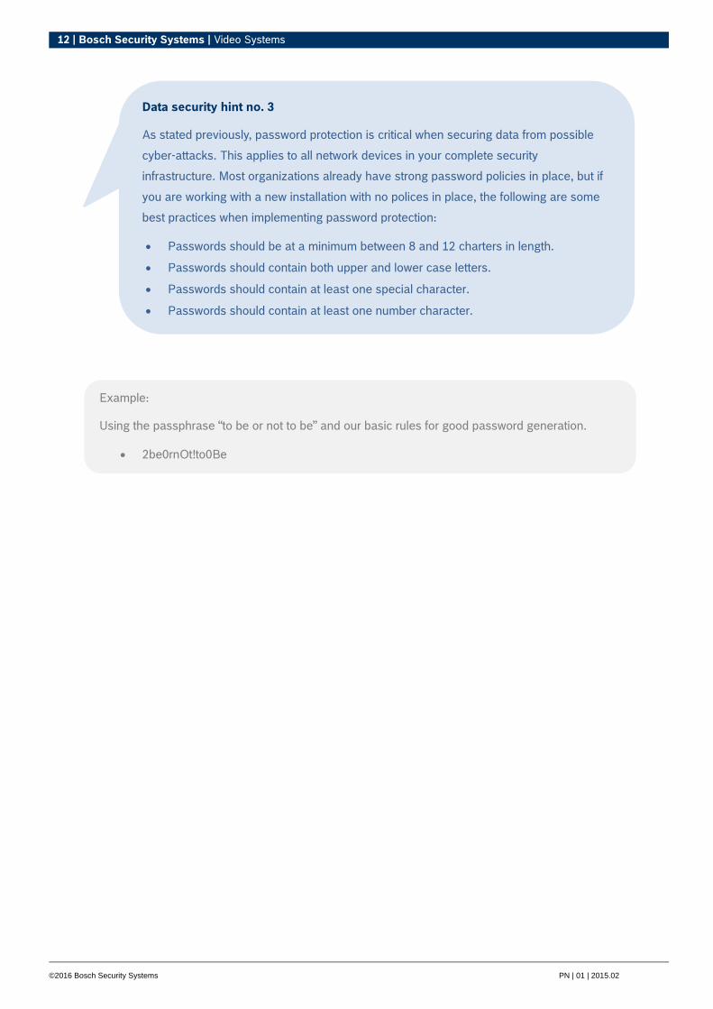
Data security hint no. 3
As stated previously, password protection is critical when securing data from possible
cyber-attacks. This applies to all network devices in your complete security
infrastructure. Most organizations already have strong password policies in place, but if
you are working with a new installation with no polices in place, the following are some
best practices when implementing password protection:
Passwords should be at a minimum between 8 and 12 charters in length.
Passwords should contain both upper and lower case letters.
Passwords should contain at least one special character.
Passwords should contain at least one number character.
Example:
Using the passphrase “to be or not to be” and our basic rules for good password generation.
2be0rnOt!to0Be
13 | Bosch Security Systems | Video Systems
©2016 Bosch Security Systems PN | 01 | 2015.02
Hardening device access
All Bosch IP video devices come with built-in multi-purpose web pages. The device-specific web pages
support both live and playback video functions, as well as some specific configuration settings that may not be
accessible via a video management system. The built-in user accounts act as the access to the different
sections of the dedicated web pages. While the web page access cannot be completely disabled via the web
page itself – the Configuration Manager could be used for –, there are several methods to cloak the presence
of the device, restrict access, and manage video port usage.
General network port usage and video transmission:
All Bosch IP video devices utilize Remote Control Protocol Plus (RCP+) for detection, control, and
communications. RCP+ is a proprietary Bosch protocol and uses specific static ports to detect and
communicate with Bosch IP video devices – 1756, 1757, and 1758. When working with Bosch Video
Management System, or another 3rd-party vendor video management system that has integrated Bosch IP
video devices via the Bosch Video SDK, the listed ports must be accessible on the network for the IP video
devices to function correctly.
Video can be streamed from the devices in several ways: UDP (Dynamic), HTTP (80), or HTTPS (443).
HTTP and HTTPS port utilization can be modified as discussed in this section of the guide. Prior to making any
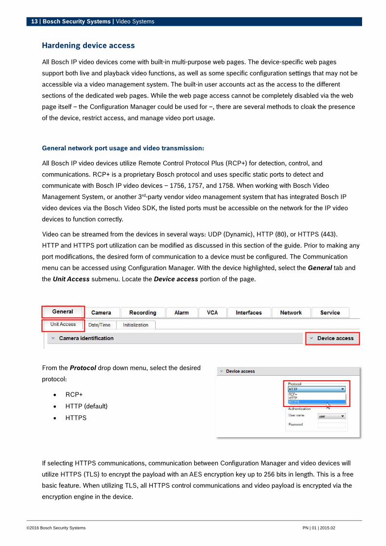
port modifications, the desired form of communication to a device must be configured. The Communication
menu can be accessed using Configuration Manager. With the device highlighted, select the General tab and
the Unit Access submenu. Locate the Device access portion of the page.
From the Protocol drop down menu, select the desired
protocol:
RCP+
HTTP (default)
HTTPS
If selecting HTTPS communications, communication between Configuration Manager and video devices will
utilize HTTPS (TLS) to encrypt the payload with an AES encryption key up to 256 bits in length. This is a free
basic feature. When utilizing TLS, all HTTPS control communications and video payload is encrypted via the
encryption engine in the device.
14 | Bosch Security Systems | Video Systems
©2016 Bosch Security Systems PN | 01 | 2015.02
Note: The encryption is specifically for the "transmission path". After video is received by either a software or
hardware decoder, the stream is permanently decrypted.
HTTP, HTTPS, and video port usage:
HTTP and HTTPS port usage on all devices can be altered or turned off. Encrypted communication can be
enforced by disabling RCP+ port as well as the HTTP port, forcing all communication to use encryption.
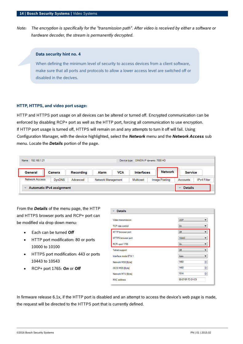
If HTTP port usage is turned off, HTTPS will remain on and any attempts to turn it off will fail. Using
Configuration Manager, with the device highlighted, select the Network menu and the Network Access sub
menu. Locate the Details portion of the page.
From the Details of the menu page, the HTTP
and HTTPS browser ports and RCP+ port can
be modified via drop down menu:
Each can be turned Off
HTTP port modification: 80 or ports
10000 to 10100
HTTPS port modification: 443 or ports
10443 to 10543
RCP+ port 1765: On or Off
In firmware release 6.1x, if the HTTP port is disabled and an attempt to access the device’s web page is made,
the request will be directed to the HTTPS port that is currently defined.
Data security hint no. 4
When defining the minimum level of security to access devices from a client software,
make sure that all ports and protocols to allow a lower access level are switched off or
disabled in the decives.
15 | Bosch Security Systems | Video Systems
©2016 Bosch Security Systems PN | 01 | 2015.02
The redirect feature is omitted in firmware release 6.20 and higher. If the HTTP port is disabled and the
HTTPS port has been modified to utilize a port other than 443, accessing the web pages can only be
accomplished by navigating to the devices IP address plus the assigned port.
Video software and port selection:
Adjusting these settings will also affect what port is utilized for video transmission when using video
management software in your LAN. If all IP video devices are set to HTTP port 10000, as an example, and the
Bosch Video Management System operator client is configured for “TCP tunneling”, then all video
transmissions on the network will be made across HTTP port 10000.
Example:
https://192.168.1.21:10443. Any attempts to connect to the default address will fail.
Data security hint no. 5
Depending on the deployment scenario and security goals of the installation, best practices can
vary. Disabling and redirecting port usage of either HTTP or HTTPS has its benefits. Changing
the port of either protocol can help avoid supplying information to network tools such as NMAP
(Network Mapper, free security scanner). Applications like NMAP are typically used as
reconnaissance tools to identify weaknesses in any device on a network. This technique
combined with strong password implementation adds to the overall security of the system.
16 | Bosch Security Systems | Video Systems
©2016 Bosch Security Systems PN | 01 | 2015.02
Telnet Access:
Telnet is an application layer protocol that provides communication to devices via a virtual terminal session for
maintenance and troubleshooting purposes. All Bosch IP video devices are Telnet capable, and by default
Telnet support is turned on in firmware releases up to 6.1x. From firmware release 6.20 onwards, the Telnet
port is disabled by default.
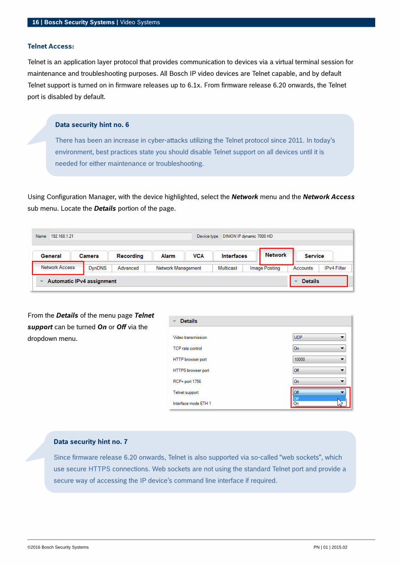
Using Configuration Manager, with the device highlighted, select the Network menu and the Network Access
sub menu. Locate the Details portion of the page.
From the Details of the menu page Telnet
support can be turned On or Off via the
dropdown menu.
Data security hint no. 7
Since firmware release 6.20 onwards, Telnet is also supported via so-called “web sockets”, which
use secure HTTPS connections. Web sockets are not using the standard Telnet port and provide a
secure way of accessing the IP device’s command line interface if required.
Data security hint no. 6
There has been an increase in cyber-attacks utilizing the Telnet protocol since 2011. In today’s
environment, best practices state you should disable Telnet support on all devices until it is
needed for either maintenance or troubleshooting.

17 | Bosch Security Systems | Video Systems
©2016 Bosch Security Systems PN | 01 | 2015.02
Cloud-based Services:
All Bosch IP video devices have the ability to communicate with Bosch Cloud-based services. Depending on
the region of deployment, this allows an IP video devices to forward alarms and other data to a central station.
There are three modes of operation for Cloud-based services:
On:
The video device will constantly poll the Cloud Server.
Auto (default):
The video devices will attempt to poll the Cloud Server a few times, and if unsuccessful, it will cease
attempting to reach the cloud server.
Off:
No polling is performed.
Cloud-based services can be easily turned off using Configuration Manager. With the device highlighted, select
the Network menu and the Advanced sub menu. Locate the Cloud-based services portion of the page.
From the menu drop down, select Off
Data Security hint no. 8
If you are utilizing Cloud-based services from Bosch, keep the default configuration.
In all other cases switch Cloud-based services mode to Off.
18 | Bosch Security Systems | Video Systems
©2016 Bosch Security Systems PN | 01 | 2015.02
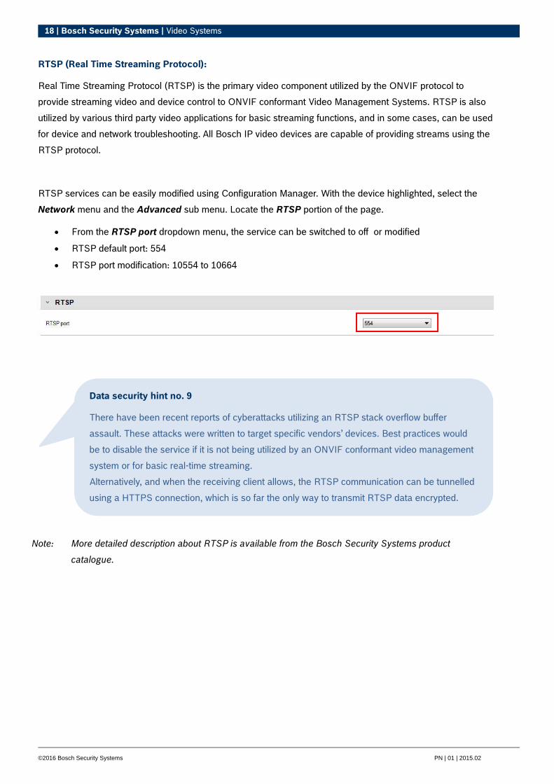
RTSP (Real Time Streaming Protocol):
Real Time Streaming Protocol (RTSP) is the primary video component utilized by the ONVIF protocol to
provide streaming video and device control to ONVIF conformant Video Management Systems. RTSP is also
utilized by various third party video applications for basic streaming functions, and in some cases, can be used
for device and network troubleshooting. All Bosch IP video devices are capable of providing streams using the
RTSP protocol.
RTSP services can be easily modified using Configuration Manager. With the device highlighted, select the
Network menu and the Advanced sub menu. Locate the RTSP portion of the page.
From the RTSP port dropdown menu, the service can be switched to off or modified
RTSP default port: 554
RTSP port modification: 10554 to 10664
Note: More detailed description about RTSP is available from the Bosch Security Systems product
catalogue.
Data security hint no. 9
There have been recent reports of cyberattacks utilizing an RTSP stack overflow buffer
assault. These attacks were written to target specific vendors’ devices. Best practices would
be to disable the service if it is not being utilized by an ONVIF conformant video management
system or for basic real-time streaming.
Alternatively, and when the receiving client allows, the RTSP communication can be tunnelled
using a HTTPS connection, which is so far the only way to transmit RTSP data encrypted.
19 | Bosch Security Systems | Video Systems
©2016 Bosch Security Systems PN | 01 | 2015.02
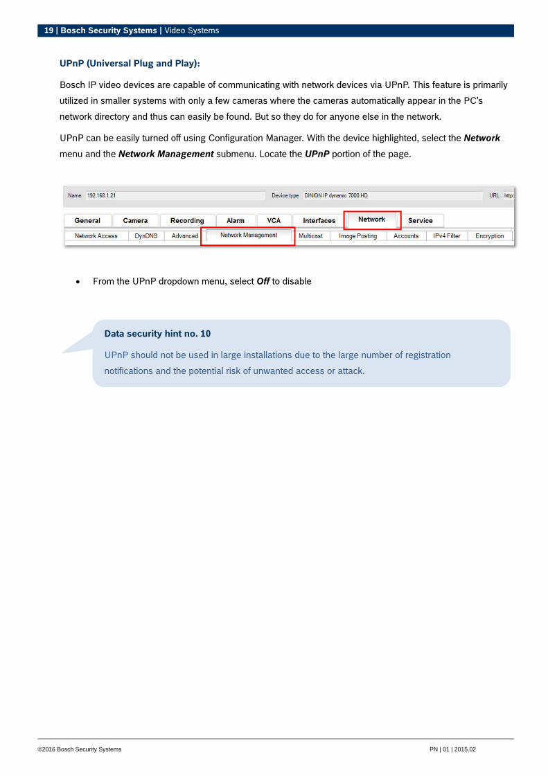
UPnP (Universal Plug and Play):
Bosch IP video devices are capable of communicating with network devices via UPnP. This feature is primarily
utilized in smaller systems with only a few cameras where the cameras automatically appear in the PC’s
network directory and thus can easily be found. But so they do for anyone else in the network.
UPnP can be easily turned off using Configuration Manager. With the device highlighted, select the Network
menu and the Network Management submenu. Locate the UPnP portion of the page.
From the UPnP dropdown menu, select Off to disable
Data security hint no. 10
UPnP should not be used in large installations due to the large number of registration
notifications and the potential risk of unwanted access or attack.

20 | Bosch Security Systems | Video Systems
©2016 Bosch Security Systems PN | 01 | 2015.02
Multicasting:
All Bosch IP video devices are capable of providing both “Multicast on Demand” or “Multicast Streaming”
video. Where unicast video transmissions are destination based, multicast is source based and this can
introduce security issues at the network level, including: group access control, group center trust, and router
trust. While router configuration is beyond the scope of this guide, there is a security solution that can be
implemented from the IP video device itself.
TTL (time-to-live) scoping defines where and how far multicast traffic is allowed to flow within a network, each
hop decreasing TTL by one. When configuring IP video devices for multicast usage, the packet TTL of the
device can be modified. Using Configuration Manager, with the device highlighted, select the Network menu
and the Multicast submenu. Locate the Multicast TTL portion of the page. Adjust the Packet TTL submenu
using the following TTL values and Scoping Limits:
TTL Value 0 = Restricted to local host
TTL Value 1 = Restricted to same subnet
TTL Value 15 = Restricted to same site
TTL Value 64 (Default) = Restricted to same region
TTL Value 127 = Worldwide
TTL Value 191 = Worldwide with limited bandwidth
TTL Value 255 = Unrestricted
Data security hint no. 11
When dealing with video surveillance data, a best practice would be to set your TTL settings to 15, restricted to same site. Or better, if you know the exact maximum number of hops, use this a TTL value.

21 | Bosch Security Systems | Video Systems
©2016 Bosch Security Systems PN | 01 | 2015.02
IPv4 filtering:
You can restrict access to any Bosch IP video device via a feature called IPv4 filtering. IPv4 filtering utilizes the
basic fundamentals of “subnetting” to define up to two allowable IP address ranges. Once defined, it denies
access from any IP address not within the defined parameters. Using Configuration Manager, with the device
highlighted, select the Network menu and the IPv4 Filter submenu.
Note: To successfully configure this feature, you must have basic understanding of subnetting or have
access to a subnet calculator. Entering incorrect values into this setting can restrict access to the
device itself and a factory default reset may need to be performed to regain access.
When adding a filter rule, you will make two entries:
A base IP address that falls within the subnet rule you create.
o The base IP address specifies which subnet you are allowing and it must fall within the
desired range.
A subnet mask that defines the IP addresses that the encoder will accept communications from.
In the example below, we entered an “IP address 1” of 192.168.1.20 and a “Mask 1” of 255.255.255.240.
This setting will restrict access from devices that fall within the defined IP range of 192.168.1.16 to .31.
While utilizing the IPv4 Filter feature devices will be able to be scanned via RCP+, but access to configuration
settings and video is not possible via clients that fall outside the allowed IP address range. This includes web
browser access. The IP video device itself does not need to be located in the allowed address range.
22 | Bosch Security Systems | Video Systems
©2016 Bosch Security Systems PN | 01 | 2015.02
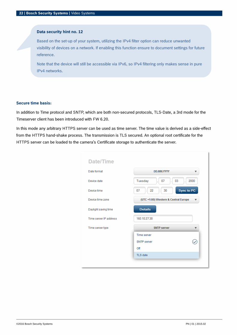
Secure time basis:
In addition to Time protocol and SNTP, which are both non-secured protocols, TLS-Date, a 3rd mode for the
Timeserver client has been introduced with FW 6.20.
In this mode any arbitrary HTTPS server can be used as time server. The time value is derived as a side-effect
from the HTTPS hand-shake process. The transmission is TLS secured. An optional root certificate for the
HTTPS server can be loaded to the camera’s Certificate storage to authenticate the server.
Data security hint no. 12
Based on the set-up of your system, utilizing the IPv4 filter option can reduce unwanted
visibility of devices on a network. If enabling this function ensure to document settings for future
reference.
Note that the device will still be accessible via IPv6, so IPv4 filtering only makes sense in pure
IPv4 networks.
23 | Bosch Security Systems | Video Systems
©2016 Bosch Security Systems PN | 01 | 2015.02
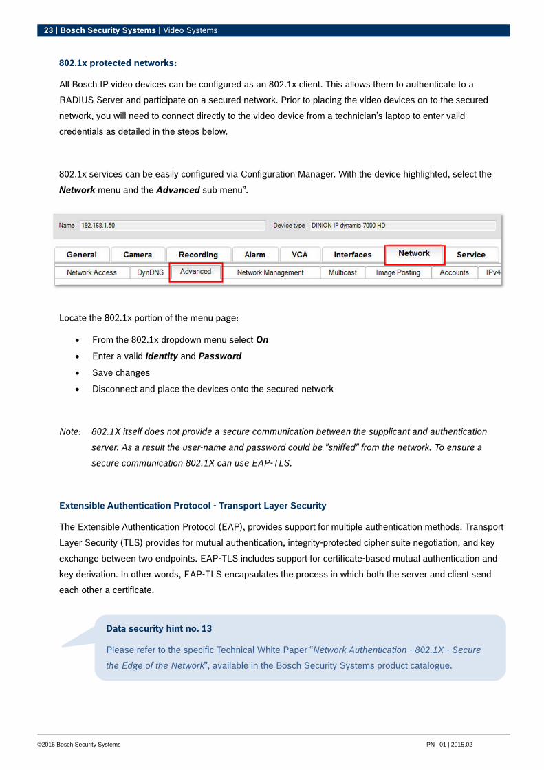
802.1x protected networks:
All Bosch IP video devices can be configured as an 802.1x client. This allows them to authenticate to a
RADIUS Server and participate on a secured network. Prior to placing the video devices on to the secured
network, you will need to connect directly to the video device from a technician’s laptop to enter valid
credentials as detailed in the steps below.
802.1x services can be easily configured via Configuration Manager. With the device highlighted, select the
Network menu and the Advanced sub menu”.
Locate the 802.1x portion of the menu page:
From the 802.1x dropdown menu select On
Enter a valid Identity and Password
Save changes
Disconnect and place the devices onto the secured network
Note: 802.1X itself does not provide a secure communication between the supplicant and authentication
server. As a result the user-name and password could be "sniffed" from the network. To ensure a
secure communication 802.1X can use EAP-TLS.
Extensible Authentication Protocol - Transport Layer Security
The Extensible Authentication Protocol (EAP), provides support for multiple authentication methods. Transport
Layer Security (TLS) provides for mutual authentication, integrity-protected cipher suite negotiation, and key
exchange between two endpoints. EAP-TLS includes support for certificate-based mutual authentication and
key derivation. In other words, EAP-TLS encapsulates the process in which both the server and client send
each other a certificate.
Data security hint no. 13
Please refer to the specific Technical White Paper “Network Authentication - 802.1X - Secure
the Edge of the Network”, available in the Bosch Security Systems product catalogue.
24 | Bosch Security Systems | Video Systems
©2016 Bosch Security Systems PN | 01 | 2015.02
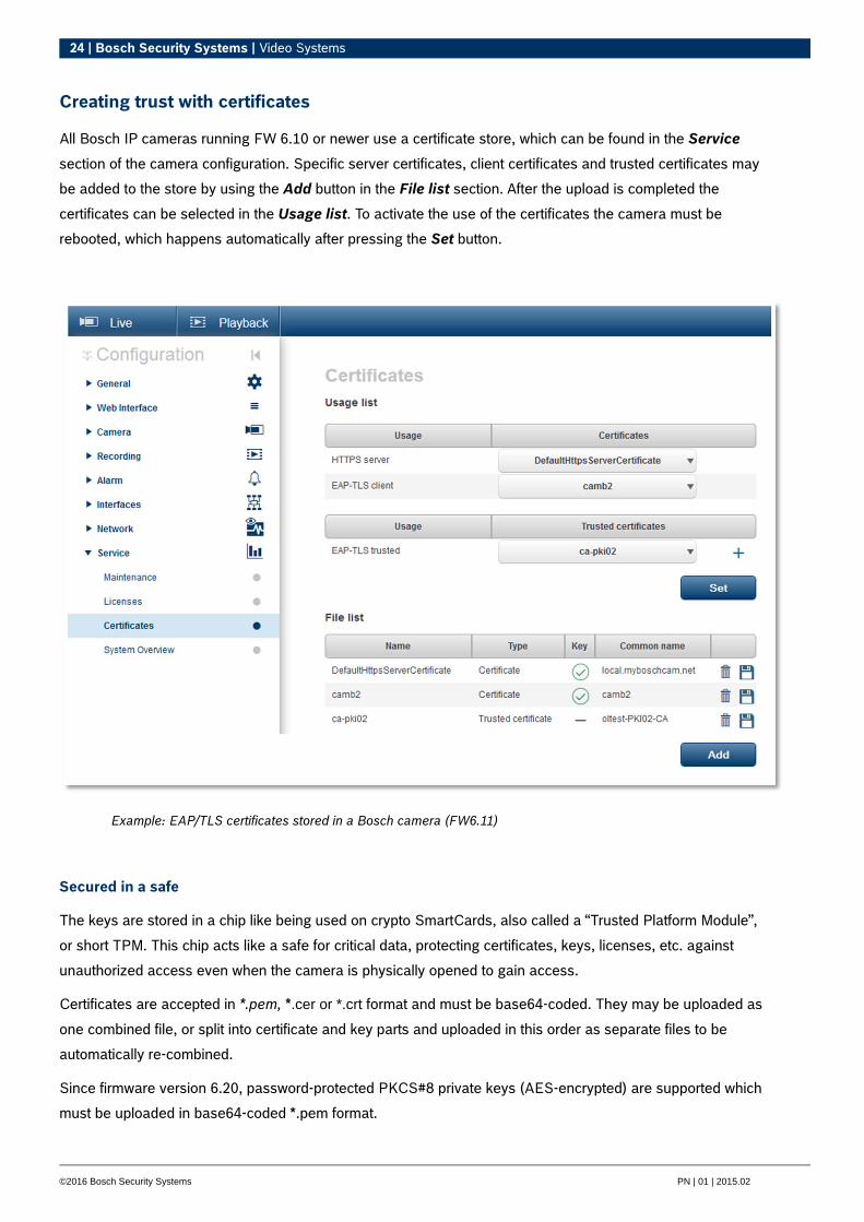
Creating trust with certificates
All Bosch IP cameras running FW 6.10 or newer use a certificate store, which can be found in the Service
section of the camera configuration. Specific server certificates, client certificates and trusted certificates may
be added to the store by using the Add button in the File list section. After the upload is completed the
certificates can be selected in the Usage list. To activate the use of the certificates the camera must be
rebooted, which happens automatically after pressing the Set button.
Example: EAP/TLS certificates stored in a Bosch camera (FW6.11)
Secured in a safe
The keys are stored in a chip like being used on crypto SmartCards, also called a “Trusted Platform Module”,
or short TPM. This chip acts like a safe for critical data, protecting certificates, keys, licenses, etc. against
unauthorized access even when the camera is physically opened to gain access.
Certificates are accepted in *.pem, *.cer or *.crt format and must be base64-coded. They may be uploaded as
one combined file, or split into certificate and key parts and uploaded in this order as separate files to be
automatically re-combined.
Since firmware version 6.20, password-protected PKCS#8 private keys (AES-encrypted) are supported which
must be uploaded in base64-coded *.pem format.

25 | Bosch Security Systems | Video Systems
©2016 Bosch Security Systems PN | 01 | 2015.02
TLS/SSL certificates:
All Bosch video devices running firmware up to FW 6.1x come with a preinstalled TLS/SSL certificate and
private key which is being used for HTTPS connections automatically. The default certificate and key is meant
for testing purposes only, as all devices come with the same defaults.
Since FW 6.20, device-specific certificates are automatically created when needed for HTTPS connections,
allowing unique authentication, and new device-specific certificates can also be created manually.
If devices are deployed in an environment where extra steps are required to validate the identity of each
individual IP video device, new certificates and private keys can be created and loaded to the video devices
themselves. New certificates can be obtained from a Certificate Authority (CA), or they can be created with an
OpenSSL Toolkit.
Device web page:
Certificates can be loaded via a video device’s web page.
To access the Certificates menu navigate to the device’s
Configuration page:
Select the Service submenu
Select the Certificates submenu
From the Certificates page (example FW 6.20) new certificates can be added and deleted, and their usage
can be defined.
26 | Bosch Security Systems | Video Systems
©2016 Bosch Security Systems PN | 01 | 2015.02
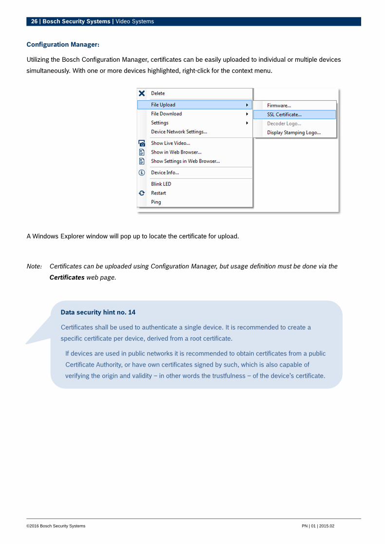
Configuration Manager:
Utilizing the Bosch Configuration Manager, certificates can be easily uploaded to individual or multiple devices
simultaneously. With one or more devices highlighted, right-click for the context menu.
A Windows Explorer window will pop up to locate the certificate for upload.
Note: Certificates can be uploaded using Configuration Manager, but usage definition must be done via the
Certificates web page.
Data security hint no. 14
Certificates shall be used to authenticate a single device. It is recommended to create a
specific certificate per device, derived from a root certificate.
If devices are used in public networks it is recommended to obtain certificates from a public
Certificate Authority, or have own certificates signed by such, which is also capable of
verifying the origin and validity – in other words the trustfulness – of the device’s certificate.
27 | Bosch Security Systems | Video Systems
©2016 Bosch Security Systems PN | 01 | 2015.02
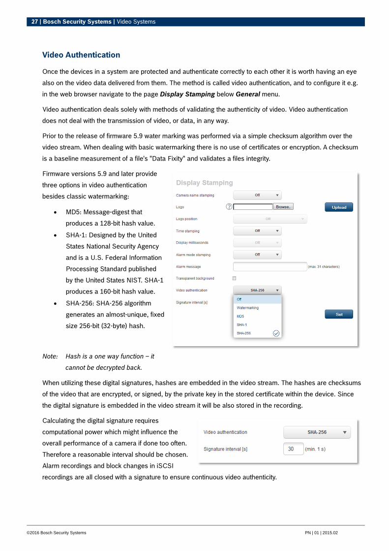
Video Authentication
Once the devices in a system are protected and authenticate correctly to each other it is worth having an eye
also on the video data delivered from them. The method is called video authentication, and to configure it e.g.
in the web browser navigate to the page Display Stamping below General menu.
Video authentication deals solely with methods of validating the authenticity of video. Video authentication
does not deal with the transmission of video, or data, in any way.
Prior to the release of firmware 5.9 water marking was performed via a simple checksum algorithm over the
video stream. When dealing with basic watermarking there is no use of certificates or encryption. A checksum
is a baseline measurement of a file's "Data Fixity" and validates a files integrity.
Firmware versions 5.9 and later provide
three options in video authentication
besides classic watermarking:
MD5: Message-digest that
produces a 128-bit hash value.
SHA-1: Designed by the United
States National Security Agency
and is a U.S. Federal Information
Processing Standard published
by the United States NIST. SHA-1
produces a 160-bit hash value.
SHA-256: SHA-256 algorithm
generates an almost-unique, fixed
size 256-bit (32-byte) hash.
Note: Hash is a one way function – it
cannot be decrypted back.
When utilizing these digital signatures, hashes are embedded in the video stream. The hashes are checksums
of the video that are encrypted, or signed, by the private key in the stored certificate within the device. Since
the digital signature is embedded in the video stream it will be also stored in the recording.
Calculating the digital signature requires
computational power which might influence the
overall performance of a camera if done too often.
Therefore a reasonable interval should be chosen.
Alarm recordings and block changes in iSCSI
recordings are all closed with a signature to ensure continuous video authenticity.

28 | Bosch Security Systems | Video Systems
©2016 Bosch Security Systems PN | 01 | 2015.02
Authors
David W. Brent, Technical Information Engineer IT Systems (ST/STS2-AM)
Konrad Simon, Product Manager IP Video (ST-VS/MKP1)
Bosch Sicherheitssysteme GmbH
Robert-Bosch-Ring 5
85630 Grasbrunn
Germany
www.boschsecurity.com
© Bosch Sicherheitssysteme GmbH, 2016