bosch video management system · bosch video management system 5 table of contents | en bosch...
TRANSCRIPT

Bosch Video Management System
en Configuration Manual


Bosch Video Management System Table of contents | en 3
Bosch Sicherheitssysteme GmbH Configuration Manual 2017.10 | V 1 | Bosch VMS Viewer ConfigurationClient
Table of contents1 Using the Help 81.1 Finding information 81.2 Printing the Help 92 Introduction 103 System overview 113.1 Hardware requirements 113.2 Software requirements 113.3 License requirements 114 Concepts 124.1 Bosch VMS Viewer 124.2 Unmanaged site 134.2.1 Structure of CSV file for importing unmanaged sites 144.3 Viewing modes of a panoramic camera 154.3.1 360° panoramic camera - floor- or ceiling mounted 154.3.2 180° panoramic camera - floor- or ceiling mounted 174.3.3 360° panoramic camera - wall mounted 184.3.4 180° panoramic camera - wall mounted 194.3.5 Cropped view on a panoramic camera 204.4 SSH Tunneling 215 Getting started 225.1 Installing Bosch VMS Viewer 225.2 Starting Bosch VMS Viewer Configuration Client 225.3 Registration and self-licensing 235.4 Preparing devices 285.5 Configuring the language of Configuration Client 285.6 Configuring the language of Operator Client 295.7 Scanning for devices 295.8 Configuring the mounting position of a panoramic camera 336 Adding an unmanaged site 346.1 Importing unmanaged sites 346.2 Configuring the time zone 357 Managing VRM storage 367.1 Scanning for VRM devices 367.2 Adding a Primary VRM manually 378 Managing encoders / decoders 388.1 Adding an encoder to a VRM pool 388.2 Moving an encoder to another pool 398.3 Adding a live only encoder 398.4 Adding a local storage encoder 408.5 Configuring an encoder / decoder 418.6 Updating the device capabilities 428.7 Configuring failover recording mode on an encoder 428.8 Configuring multiple encoders / decoders 438.9 Changing the password of an encoder / decoder 448.10 Providing the destination password for a decoder 448.11 Encrypting live video 458.12 Managing the verification of authenticity 468.12.1 Configuring the authentication 46

4 en | Table of contents Bosch Video Management System
2017.10 | V 1 | Bosch VMS Viewer ConfigurationClient
Configuration Manual Bosch Sicherheitssysteme GmbH
8.12.2 Downloading a certificate 468.12.3 Installing a certificate on a workstation 479 Managing various devices 489.1 Configuring the integration of a DVR 489.2 Adding a monitor wall 4910 Configuring the Logical Tree 5010.1 Configuring the Logical Tree 5010.2 Adding a device to the Logical Tree 5010.3 Removing a tree item 5010.4 Managing pre-configured camera sequences 5110.5 Adding a camera sequence 5210.6 Adding a folder 5211 Configuring cameras and recording settings 5311.1 Configuring PTZ port settings 5311.2 Configuring PTZ camera settings 5412 Configuring users, permissions and Enterprise Access 5512.1 Creating a user 5512.2 Creating a group or account 5612.3 Creating a dual authorization group 5712.4 Configuring LDAP settings 5812.5 Associating an LDAP group 5812.6 Configuring operating permissions 5912.7 Configuring permissions for Logical Tree 5912.8 Configuring camera permissions 6013 Managing configuration data 6113.1 Activating the working configuration 6113.2 Activating a configuration 6213.3 Exporting configuration data 6213.4 Importing configuration data 6313.5 Checking the status of your encoders/decoders 6414 Global Configuration Client windows 6514.1 Activation Manager dialog box 6514.2 Activate Configuration dialog box 6514.3 License Manager dialog box 6614.4 License Activation dialog box 6614.5 Options dialog box 6714.6 License Investigator dialog box 6715 Devices page 6815.1 Initial Device Scan dialog box 6815.2 DVR (Digital Video Recorder) page 6815.2.1 Add DVR dialog box 6915.2.2 Settings tab 6915.2.3 Cameras tab 6915.2.4 Inputs tab 6915.2.5 Relays tab 6915.3 Workstation page 6915.3.1 Settings page 7015.4 Decoders page 7115.4.1 Add Encoder / Add Decoder dialog box 72

Bosch Video Management System Table of contents | en 5
Bosch Sicherheitssysteme GmbH Configuration Manual 2017.10 | V 1 | Bosch VMS Viewer ConfigurationClient
15.4.2 Edit Encoder / Edit Decoder dialog box 7215.4.3 Enter password dialog box 7415.5 Monitor Wall page 7515.5.1 Add Monitor Wall dialog box 7615.6 Bosch VMS Scan Wizard 7715.7 VRM Devices page 7815.7.1 Add VRM dialog box 7815.8 Live Only page 7915.9 Local Storage page 7915.10 Unmanaged Sites page 7915.10.1 Add Unmanaged Site dialog box 8015.10.2 Unmanaged Site page 8015.10.3 Add Unmanaged Network Device dialog box 8015.10.4 Unmanaged Network Device page 8116 Bosch Encoder / Decoder page 8216.1 Enter password dialog box 8316.2 Unit Access page 8316.2.1 Identification / Camera identification 8316.2.2 Camera name 8416.2.3 Version information 8416.3 Date/Time page 8416.4 Installer / Initialization menu 8516.4.1 Application variant 8516.4.2 Base frame rate 8516.4.3 Camera LED 8516.4.4 Mirror image 8516.4.5 Flip image 8516.4.6 Menu button 8516.4.7 Heater 8516.4.8 Reboot device 8516.4.9 Factory defaults 8516.4.10 Lens Wizard 8516.5 Privacy Masks page 8516.6 Recording Management page 8616.7 Recording preferences page 8616.8 Video Input page 8716.9 Picture settings - Scene mode 8816.9.1 Current mode 8816.9.2 Mode ID 8816.9.3 Copy mode to 8816.9.4 Restore Mode Defaults 8816.9.5 Scene mode factory defaults 8816.9.6 Scene mode factory defaults 8916.9.7 Scene mode factory defaults 8916.10 Picture settings - Color 9016.10.1 White balance 9016.10.2 White balance 9116.10.3 White balance 9116.10.4 White balance 92

6 en | Table of contents Bosch Video Management System
2017.10 | V 1 | Bosch VMS Viewer ConfigurationClient
Configuration Manual Bosch Sicherheitssysteme GmbH
16.11 Picture settings - ALC 9216.11.1 ALC mode 9216.11.2 ALC level 9216.11.3 Saturation (av-pk) 9316.11.4 Exposure/frame rate 9316.11.5 Day/night 9316.12 Encoder Regions page 9416.13 Camera page 9416.13.1 ALC 9616.13.2 Scene mode 9716.13.3 Scene Mode Scheduler 9716.13.4 WDR 9816.13.5 Sharpness level 9816.13.6 Backlight Compensation 9816.13.7 Contrast enhancement 9816.13.8 Intelligent DNR 9816.14 Lens page 9816.14.1 Focus 9816.14.2 Iris 9916.14.3 Zoom 9916.15 PTZ page 9916.16 Prepositions and Tours page 10016.17 Sectors page 10016.18 Misc page 10116.19 Logs page 10116.20 Audio page 10116.21 Relay page 10116.22 Periphery page 10216.22.1 COM1 10216.23 VCA page 10316.23.1 Motion detector (MOTION+ only) 10416.23.2 Select Area dialog box 10516.23.3 Tamper detection 10516.24 Network Access page 10716.24.1 JPEG posting 10816.24.2 FTP server 10816.25 DynDNS 10916.25.1 Enable DynDNS 10916.25.2 Provider 10916.25.3 Host name 10916.25.4 User name 10916.25.5 Password 10916.25.6 Force registration now 10916.25.7 Status 10916.26 Network Management 11016.26.1 SNMP 11016.26.2 UPnP 11016.26.3 Quality of Service 11016.27 Advanced page 110

Bosch Video Management System Table of contents | en 7
Bosch Sicherheitssysteme GmbH Configuration Manual 2017.10 | V 1 | Bosch VMS Viewer ConfigurationClient
16.27.1 SNMP 11016.27.2 802.1x 11116.27.3 RTSP 11116.27.4 UPnP 11116.27.5 TCP metadata input 11116.28 Multicast page 11116.29 Accounts 11216.30 IP v4 Filter 11316.31 Licenses page 11316.32 Certificates page 11316.33 Maintenance page 11416.34 Decoder page 11416.34.1 Decoder profile 11416.34.2 Monitor display 11417 Structure page 11617.1 Sequence Builder dialog box 11717.2 Add Sequence dialog box 11817.3 Add Sequence Step dialog box 11818 Cameras and Recording page 11918.1 Cameras page 11918.2 PTZ/ROI Settings dialog box 12219 User Groups page 12319.1 New User Group/Enterprise User Group/Enterprise Account dialog box 12419.2 User Group Properties page 12519.3 User Properties page 12619.4 Admin Group 12719.5 Add New Dual Authorization Group dialog box 12719.6 Logon Pair Properties page 12819.7 Select User Groups dialog box 12819.8 Camera Permissions page 12919.9 Copy User Group Permissions dialog box 13019.10 LDAP Server Settings dialog box 13019.11 Logical Tree page 13319.12 Operator Features page 13319.13 User Interface page 134
Glossary 136Index 141

8 en | Using the Help Bosch Video Management System
2017.10 | V 1 | Bosch VMS Viewer ConfigurationClient
Configuration Manual Bosch Sicherheitssysteme GmbH
1 Using the HelpNotice!This document describes some functions that are not available for Bosch VMS Viewer.
To find out more about how to do something in Bosch VMS, access the online Help using anyof the following methods.To use the Contents, Index, or Search:4 On the Help menu, click Help. Use the buttons and links to navigate.
To get help on a window or dialog:
4 On the toolbar, click .
OR4 Press F1 for help on any program window or dialog.
1.1 Finding information You can find information in the Help in several ways.To find information in the Online Help:1. On the Help menu, click Help.2. If the left-hand pane is not visible, click the Show button.3. In the Help window, do the following:
Click: To:
Contents Display the table of contents for the Online Help. Click each book todisplay pages that link to topics, and click each page to display thecorresponding topic in the right-hand pane.
Index Search for specific words or phrases or select from a list of indexkeywords. Double-click the keyword to display the corresponding topicin the right-hand pane.
Search Locate words or phrases within the content of your topics. Type theword or phrase in the text field, press ENTER, and select the topic youwant from the list of topics.
Texts of the user interface are marked bold.4 The arrow invites you to click on the underlined text or to click an item in the application.
Related Topics4 Click to display a topic with information on the application window you currently use.
This topic provides information on the application window controls.
Caution!Medium risk (without safety alert symbol): Indicates a potentially hazardous situation.If not avoided, this may result in property damage or risk of damage to the unit.Cautionary messages should be heeded to help you avoid data loss or damaging the system.
Notice!This symbol indicates information or a company policy that relates directly or indirectly to thesafety of personnel or protection of property.

Bosch Video Management System Using the Help | en 9
Bosch Sicherheitssysteme GmbH Configuration Manual 2017.10 | V 1 | Bosch VMS Viewer ConfigurationClient
1.2 Printing the HelpWhile using the Online Help, you can print topics and information right from the browserwindow.To print a Help topic:1. Right-click in the right pane and select Print.
The Print dialog box opens.2. Click Print. The topic is printed to the specified printer.

10 en | Introduction Bosch Video Management System
2017.10 | V 1 | Bosch VMS Viewer ConfigurationClient
Configuration Manual Bosch Sicherheitssysteme GmbH
2 IntroductionThe Bosch VMS Viewer is an IP video security application for live viewing and playback videoof Bosch network attached cameras and recorders. The software package consists of anOperator Client for live viewing and playback of video and a Configuration Client. The BoschVMS Viewer supports the current Bosch IP video product portfolio as well as legacy Boschvideo devices.
Click the link to access the Open Source Software licenses used by Bosch VMS Viewer:http://www.boschsecurity.com/oss.
1 Menu bar
2 Toolbar
3 Instant playback control
4 Performance meter
5 Controls for Image panes
6 Image window
7 PTZ Control window
8 Logical Tree window
9 Favorites Tree window
10 Bookmarks window

Bosch Video Management System System overview | en 11
Bosch Sicherheitssysteme GmbH Configuration Manual 2017.10 | V 1 | Bosch VMS Viewer ConfigurationClient
3 System overviewNotice!This document describes some functions that are not available for Bosch VMS Viewer.
Refer to the Release Notes of the current Bosch VMS version for supported versions offirmware and hardware and other important information.See data sheets on Bosch workstations and servers for information on computers whereBosch VMS can be installed.The Bosch VMS software modules can optionally be installed on one PC.
3.1 Hardware requirementsSee the data sheet for Bosch VMS. Data sheets for platform PCs are also available.
3.2 Software requirementsViewer cannot be installed where any other Bosch VMS component is installed.
3.3 License requirementsSee the data sheet for Bosch VMS for the available licenses.

12 en | Concepts Bosch Video Management System
2017.10 | V 1 | Bosch VMS Viewer ConfigurationClient
Configuration Manual Bosch Sicherheitssysteme GmbH
4 ConceptsThis chapter provides background information on selected issues.
Notice!This document describes some functions that are not available for Bosch VMS Viewer.
4.1 Bosch VMS ViewerBosch VMS Viewer is a free of charge variant of Bosch VMS.The Bosch VMS Viewer system is an all in one Bosch VMS solution for small to mediuminstallations and gives the user of Bosch VMS Viewer Operator Client access to live andrecorded video data. Compared to a Bosch VMS system, Bosch VMS Viewer system supportsonly a subset of the Bosch VMS features and devices. The software is designed for the basicvideo surveillance operations, like live viewing, playback video, search in recorded video andexport of video data.Bosch VMS Viewer consists of a Bosch VMS Operator Client and Bosch VMSConfiguration Client. Both applications show a reduced feature set compared to the twoapplications in Bosch VMS.Bosch VMS Viewer Configuration Client is used to add devices to the system, to define theorder of the device and to setup users and user preferences.
Device ConfigurationFollowing device are supported:– BRS / Dibos– Digital Video Recorders– Monitor / decoders (only digital monitor walls)– VRM devices– Live only and local storage cameras– unmanaged sitesBosch VMS Viewer does not overwrite the configuration of the devices, the devices are addedwith existing configuration to Bosch VMS Viewer. If supported by devices, the configuration ofthe device can be changed with Bosch VMS Viewer.
Structure of Logical TreeCameras, inputs and relays can be structured in the Maps and Structure page of Bosch VMSViewer. Devices can be grouped in folders and the order of devices can be configured.
User groupsIn the user group settings, users can be configured, that are allowed to access Bosch VMSViewer. Depending on the user group settings, users have different rights in Bosch VMSViewer Operator Client.
Supported featuresBosch VMS Viewer Operator Client supports the following features:Live viewing:– PTZ cameras– Favorites– Sequences– Instant replay– Save and print images– Select stream

Bosch Video Management System Concepts | en 13
Bosch Sicherheitssysteme GmbH Configuration Manual 2017.10 | V 1 | Bosch VMS Viewer ConfigurationClient
– BookmarksPlayback video:– Smart Motion search– Forensic Search– Save and print images– Export of video data– Bookmarks
4.2 Unmanaged siteOperator ClientThe user of Operator Client of system A can connect to another system B. System B is called
unmanaged site, indicated by . The user can for example perform the following tasks onthe video network devices of system B:– Display live and playback.– Export video.– Delete video.– Protect and unprotect video.– Create and print a snapshot.The user of Operator Client can switch the time zone if an unmanaged site is configured to belocated in another time zone.
Configuration ClientIn the Device Tree of Configuration Client of Bosch VMS A, you can add the network devices ofsystem B to an unmanaged site item.You can add the following device types as system B:– DVR / DIVAR AN– Bosch VMS / DIVAR IP 3000/7000– IP cameras / encoders from BoschYou can add an unmanaged site to the Logical Tree multiple times, for example to foldersconfigured as maps.If port mapping is enabled in the remote access settings of system B then the public networkaddress can also be used in the settings of the unmanaged network device configured insystem A.You can configure the time zone of an unmanaged site. This is useful when a user ofOperator Client wants to access an unmanaged site using a computer with Operator Clientlocated in another time zone than this unmanaged site.
Credentials for an unmanaged siteWhen adding a network device to an unmanaged site, you must type in the IP address andselect the correct device type of this network device. It is optional to enter credentials for thisnetwork device. IP address and the credentials are not checked from withinConfiguration Client.When the user of Operator Client connects to an unmanaged site, the credentials that wereentered in Configuration Client, are used for logon to the network devices of this unmanagedsite if available. If no credentials are available in the configuration, the credentials of thecurrent Operator Client logon are automatically used.
Security considerationsWhen a user of Operator Client in system A accesses system B via unmanaged site access,keep the following security related considerations in mind:

14 en | Concepts Bosch Video Management System
2017.10 | V 1 | Bosch VMS Viewer ConfigurationClient
Configuration Manual Bosch Sicherheitssysteme GmbH
– All user actions on cameras of system B performed in system A, are not logged on boththe systems.
– Operator Client of system A does not enforce the operating permissions configured insystem B.
– Operator Client of system A enforces the device permissions configured in system B.– If an administrator of system A knows a valid user account of system B, system B cannot
prevent system A from connecting to system B as an unmanaged network device.
Limitations– Bookmarks can be saved and used, but are not persistent after the Operator Client has
been restarted.
See also– Adding an unmanaged site, page 34
4.2.1 Structure of CSV file for importing unmanaged sitesYou can prepare a CSV file for importing unmanaged sites in Bosch VMS.The list separator that is configured in the Regional Settings of your Operating System, is usedas separator for the CSV file.The computer where you edit the CSV file must have the same regional settings as thecomputer running Configuration Client.To change the list separator (Windows 7 as an example):4 Click Start > Control Panel > Region and Language > Additional Settings > In the List
separator: list, select the desired character.The definition headline in the CSV file at line 4 is mandatory.All information above the definition headline is ignored during import.The definition headline defines the mapping of the columns to the unmanaged sites inBosch VMS.Possible values are listed in the following table.
Column title Description
Site Creates an unmanaged site. This is only allowed to appearonce per line.
ConnectionString Creates a device by connecting to the specified URI.
User The user name for authentication. This field can be empty.
Password The password for authentication. This field can be empty.
TimeZone The time zone of the Configuration Client computer. This fieldcan be empty. If you leave this field empty or omit it, the timezone of the Configuration Client computer is used.Please write down the exact string that you find here:
Main window > Devices > Right-click > AddUnmanaged Network Device command > Add UnmanagedNetwork Device dialog box > list
Below the definition headline, each line represents one device.

Bosch Video Management System Concepts | en 15
Bosch Sicherheitssysteme GmbH Configuration Manual 2017.10 | V 1 | Bosch VMS Viewer ConfigurationClient
See also– Importing unmanaged sites, page 34
4.3 Viewing modes of a panoramic cameraThis chapter illustrates the viewing modes of a panoramic camera which are available inBosch VMS.The following viewing modes are available:– Circle view– Panorama view– Cropped viewPanorama and cropped view modes are created by the dewarping process in Bosch VMS. Edgedewarping is not used.The administrator must configure the mounting position of a panoramic camera inConfiguration Client.You can resize the Image pane of a camera as required. The Image pane ratio is not restrictedto the 4:3 or 16:9 aspect ratio.
See also– Configuring the mounting position of a panoramic camera, page 33
4.3.1 360° panoramic camera - floor- or ceiling mountedThe following figure illustrates the dewarping of a 360° camera which is floor- or ceilingmounted.

16 en | Concepts Bosch Video Management System
2017.10 | V 1 | Bosch VMS Viewer ConfigurationClient
Configuration Manual Bosch Sicherheitssysteme GmbH
1 Full circle image 3 Dewarping
2 Snipping line (operator can change itsposition when not zoomed in)
4 Panorama view

Bosch Video Management System Concepts | en 17
Bosch Sicherheitssysteme GmbH Configuration Manual 2017.10 | V 1 | Bosch VMS Viewer ConfigurationClient
4.3.2 180° panoramic camera - floor- or ceiling mountedThe following figure illustrates the dewarping of a 180° camera which is floor- or ceilingmounted.
1 Full circle image 3 Dewarping
2 Snipping line (operator can change itsposition when not zoomed in)
4 Panorama view

18 en | Concepts Bosch Video Management System
2017.10 | V 1 | Bosch VMS Viewer ConfigurationClient
Configuration Manual Bosch Sicherheitssysteme GmbH
4.3.3 360° panoramic camera - wall mountedThe following figure illustrates the dewarping of a 360° camera which is wall mounted.
1 Full circle image 3 Panorama view
2 Dewarping

Bosch Video Management System Concepts | en 19
Bosch Sicherheitssysteme GmbH Configuration Manual 2017.10 | V 1 | Bosch VMS Viewer ConfigurationClient
4.3.4 180° panoramic camera - wall mountedThe following figure illustrates the dewarping of a 180° camera which is wall mounted.
1 Full circle image 3 Panorama view
2 Dewarping

20 en | Concepts Bosch Video Management System
2017.10 | V 1 | Bosch VMS Viewer ConfigurationClient
Configuration Manual Bosch Sicherheitssysteme GmbH
4.3.5 Cropped view on a panoramic cameraThe following example figure illustrates the cropping of a 360° camera which is floor- or ceilingmounted.The rectilinear section used for cropping is fixed. You can change the section in the croppedImage pane using the available PTZ controls.
1 Full circle image 4 Panorama view
2 Snipping line (operator can change itsposition when not zoomed in)
5 Cropping
3 Dewarping 6 Cropped Image pane

Bosch Video Management System Concepts | en 21
Bosch Sicherheitssysteme GmbH Configuration Manual 2017.10 | V 1 | Bosch VMS Viewer ConfigurationClient
4.4 SSH TunnelingBosch VMS provides remote connectivity utilizing Secure Shell (SSH) tunneling.SSH tunneling constructs an encrypted tunnel established by an SSH protocol/socketconnection. This encrypted tunnel can provide transport to both encrypted and un-encryptedtraffic. The Bosch SSH implementation also utilizes Omni-Path protocol, which is a highperformance low latency communications protocol developed by Intel.
Technical aspects and restrictions– SSH tunneling utilizes port 5322. This port cannot be modified.– The SSH Service must be installed on the same server as the Bosch VMS Management
Server.– User accounts must have a configured password. User accounts without a password
cannot log on utilizing a SSH connection.– Configuration Client cannot connect remotely via SSH. Configuration Client connection
must be done via port mapping.– Operator Client checks connection with SSH service every 15 seconds. If the connection
is interrupted, Operator Client retests the connection every minute.
Port mapping4 Configure one port forwarding for the Bosch VMS Management Server to utilize port 5322
for both internal and external connections.This is the only port mapping entry that you need to make for the entire system.Bosch VMS port mapping is not required.
Encrypted communicationAfter the connection is established via a SSH tunnel, all communications between theBosch VMS Management Server and a remote client are encrypted.

22 en | Getting started Bosch Video Management System
2017.10 | V 1 | Bosch VMS Viewer ConfigurationClient
Configuration Manual Bosch Sicherheitssysteme GmbH
5 Getting startedThis chapter provides information on how to get started with Bosch VMS Viewer.
5.1 Installing Bosch VMS Viewer
Notice!Installing Bosch VMS Viewer is only allowed on computers, where no other Bosch VMScomponent is installed.
To install Bosch VMS Viewer:1. Start the Bosch VMS Viewer Setup with a double click on the Setup icon. The Bosch VMS
Viewer InstallShield Wizard is displayed.2. Click Install to install Microsoft .NET Framework 4.6 Full.3. On the Welcome screen click Next to continue.4. Accept End User License Agreement and click Next to continue.5. Select the desired installation folder and click Next to continue.
Note: It is not recommended to change the default folder.6. Click Install to start the installation. Bosch VMS Viewer Installation Wizard installs all
components and shows a progress bar.7. Click Finish to finish the installation.8. Reboot workstation after the installation is finished.
5.2 Starting Bosch VMS Viewer Configuration ClientTo start Bosch VMS Viewer Configuration Client:1. From the Start menu, select Programs > Bosch VMS Viewer > Configuration Client or
double click the Configuration Client icon.
The Login window of the Bosch VMS Configuration Client is displayed:
2. Fill in the following fields:
Bosch Video Management System Getting started | en 23
Bosch Sicherheitssysteme GmbH Configuration Manual 2017.10 | V 1 | Bosch VMS Viewer ConfigurationClient
– User Name: type your user name.When you start the application for the first time, enter Admin as user name, nopassword is required.
– Password: type your password.– Connection: select Bosch VMS Viewer to log on to Bosch VMS Viewer.
Note: In the Connection: list, by default the local Bosch VMS Viewer is selected. Select New to add the IP address of a Bosch VMS Management Server and log ondirectly to a Bosch VMS Management Server.
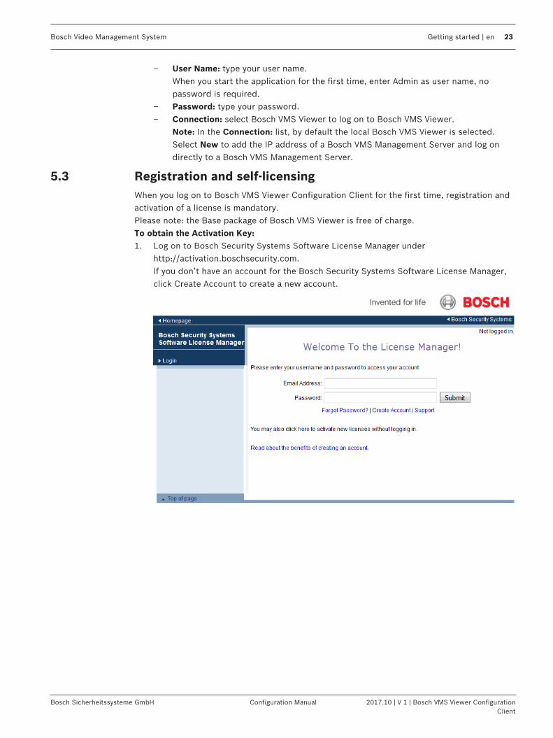
5.3 Registration and self-licensingWhen you log on to Bosch VMS Viewer Configuration Client for the first time, registration andactivation of a license is mandatory.Please note: the Base package of Bosch VMS Viewer is free of charge.To obtain the Activation Key:1. Log on to Bosch Security Systems Software License Manager under
http://activation.boschsecurity.com.If you don’t have an account for the Bosch Security Systems Software License Manager,click Create Account to create a new account.

24 en | Getting started Bosch Video Management System
2017.10 | V 1 | Bosch VMS Viewer ConfigurationClient
Configuration Manual Bosch Sicherheitssysteme GmbH
2. Click Create Demo Licenses.
3. In the list of demo licenses, click Submit to create a Bosch VMS Viewer demo license.4. In the License Activation dialog box, enter the computer signature of your Bosch VMS
Viewer and fill in all mandatory fields.
To retrieve the computer signature:1. Open License Manager (During first log on the License Manager dialog box opens
automatically. To manually open the License Manager dialog box, in the Bosch VMSViewer Configuration Client click Tools and then click License Manager...).
2. In the License Manager dialog box, select the Bosch VMS Viewer package.

Bosch Video Management System Getting started | en 25
Bosch Sicherheitssysteme GmbH Configuration Manual 2017.10 | V 1 | Bosch VMS Viewer ConfigurationClient
3. Click Activate.
4. The License Activation dialog box is displayed.

26 en | Getting started Bosch Video Management System
2017.10 | V 1 | Bosch VMS Viewer ConfigurationClient
Configuration Manual Bosch Sicherheitssysteme GmbH
5. Copy the computer signature.
Notice!The computer signature is used for licensing. This computer signature can change afterexchanging hardware on the computer. When the computer signature is changed, the licensefor the system becomes invalid.To avoid licensing problems, finish the hardware and software configuration before yougenerate the computer signature. Make sure your computer is connected to the networkbefore obtaining the computer signature. The following hardware changes can make the system license invalid:Exchanging the network interface card.Adding a VMWare or VPN virtual network interface.Adding or activating a WLAN network interface
To create the Activation Key:1. In Bosch Security Systems Software License Manager, in the Computer Signature field,
paste the computer signature and fill in all mandatory fields.
2. Click Submit to generate the free of charge license.

Bosch Video Management System Getting started | en 27
Bosch Sicherheitssysteme GmbH Configuration Manual 2017.10 | V 1 | Bosch VMS Viewer ConfigurationClient
3. The License Activation window is displayed:
4. Copy the activation key.

28 en | Getting started Bosch Video Management System
2017.10 | V 1 | Bosch VMS Viewer ConfigurationClient
Configuration Manual Bosch Sicherheitssysteme GmbH
To activate your system:1. In the License Activation dialog box, paste the License Activation Key.
2. Click Activate.
5.4 Preparing devicesBosch video devices that shall be added to a Bosch VMS Viewer must have an assigned fixedIP address and need to be preconfigured. To assign an IP address to the device, use thedevice configuration webpage or use Bosch tools to assign IP addresses. Recording relevantsettings have to be done on the recorders via device configuration tools or device web pages.For device specific configuration, please refer to the configuration or user manual of thedesired device.
5.5 Configuring the language of Configuration ClientYou configure the language of your Configuration Client independently of the language of yourWindows installation.
To configure the language:1. On the Settings menu, click Options....
The Options dialog box is displayed.2. In the Language list, select the desired language.
If you select the System language entry, the language of your Windows installation isused.
3. Click OK.The language is switched after the next restart of the application.

Bosch Video Management System Getting started | en 29
Bosch Sicherheitssysteme GmbH Configuration Manual 2017.10 | V 1 | Bosch VMS Viewer ConfigurationClient
5.6 Configuring the language of Operator ClientYou configure the language of your Operator Client independently of the language of yourWindows installation and of your Configuration Client. This step is performed in theConfiguration Client.
To configure the language:
1. Click User Groups > . Click the User Group Properties tab. Click the OperatingPermissions tab.
2. In the Language list, select the desired language.
3. Click to save the settings.
4. Click to activate the configuration. Restart Operator Client.
5.7 Scanning for devices
Main window > DevicesYou can scan for the following devices to add them with the help of the Bosch VMS ScanWizard dialog box:– VRM devices– Encoders– Live only encoders– Live only ONVIF encoders– Local storage encoders– Decoders– Video Streaming Gateway (VSG) devices– DVR devices– VIDOS NVRs
See also– To add VRM devices via scan:, page 29– To add encoders via scan:, page 30– To add Bosch live only devices via scan:, page 30– To add ONVIF live only devices via scan:, page 31– To add local storage encoders via scan:, page 31– To add VSG devices via scan:, page 32– To add DVR devices via scan:, page 32
To add VRM devices via scan:
1. Right-click and click Scan for VRM Devices.The Bosch VMS Scan Wizard dialog box is displayed.
2. Select the desired check boxes for the devices that you want to add.3. In the Role list, select the desired role.
It depends on the current type of the VRM device which new role you can select.If you select Mirrored or Failover, the next configuration step is additionally required.

30 en | Getting started Bosch Video Management System
2017.10 | V 1 | Bosch VMS Viewer ConfigurationClient
Configuration Manual Bosch Sicherheitssysteme GmbH
4. Click Next >>. The Authenticate Devices dialog box of the wizard is displayed.
5. Type in the password for each device that is protected by a password.Password check is performed automatically, when you do not enter a further character inthe password field for a few seconds or you click outside the password field.If the passwords of all devices are identical, you can enter it in the first Password field.Then right-click this field and click Copy cell to column.
In the Status column, the successful logons are indicated with .
The failed logons are indicated with 6. Click Finish.
The device is added to your Bosch VMS.
To add encoders via scan:
1. Right-click and click Scan for Encoders.The Bosch VMS Scan Wizard dialog box is displayed.
2. Select the required encoders, select the desired VRM pool and click Assign to assignthem to the VRM pool.
3. Click Next >>. The Authenticate Devices dialog box of the wizard is displayed.
4. Type in the password for each device that is protected by a password.Password check is performed automatically, when you do not enter a further character inthe password field for a few seconds or you click outside the password field.If the passwords of all devices are identical, you can enter it in the first Password field.Then right-click this field and click Copy cell to column.
In the Status column, the successful logons are indicated with .
The failed logons are indicated with
indicates that the device requires an initial password.To set the initial password, enter it in the Password field.
The status changes to .Repeat this step for all devices that require an initial password.Note: As long as you have not set the initial password for all devices in the list thatrequire an initial password, you cannot continue.
5. Click Finish. The device is added to your Bosch VMS.
To add Bosch live only devices via scan:
1. Right-click and click Scan for Live Only Encoders.The Bosch VMS Scan Wizard dialog box is displayed.
2. Select the desired check boxes for the devices that you want to add.3. Click Next >>.
The Authenticate Devices dialog box of the wizard is displayed.

Bosch Video Management System Getting started | en 31
Bosch Sicherheitssysteme GmbH Configuration Manual 2017.10 | V 1 | Bosch VMS Viewer ConfigurationClient
4. Type in the password for each device that is protected by a password.Password check is performed automatically, when you do not enter a further character inthe password field for a few seconds or you click outside the password field.If the passwords of all devices are identical, you can enter it in the first Password field.Then right-click this field and click Copy cell to column.
In the Status column, the successful logons are indicated with .
The failed logons are indicated with
indicates that the device requires an initial password.To set the initial password, enter it in the Password field.
The status changes to .Repeat this step for all devices that require an initial password.Note: As long as you have not set the initial password for all devices in the list thatrequire an initial password, you cannot continue.
5. Click Finish. The device is added to your Bosch VMS.
To add ONVIF live only devices via scan:
1. Right-click and click Scan for Live Only ONVIF Encoders. The Bosch VMS Scan Wizard dialog box is displayed.
2. Select the desired check boxes for the devices that you want to add.3. Click Next >>.
The Authenticate Devices dialog box of the wizard is displayed.4. Type in the password for each device that is protected by a password.
Password check is performed automatically, when you do not enter a further character inthe password field for a few seconds or you click outside the password field.If the passwords of all devices are identical, you can enter it in the first Password field.Then right-click this field and click Copy cell to column.
In the Status column, the successful logons are indicated with .
The failed logons are indicated with 5. Click Finish.
The device is added to your Bosch VMS.
To add local storage encoders via scan:
1. Right-click and click Scan for Local Storage Encoders.The Bosch VMS Scan Wizard dialog box is displayed.
2. Select the desired check boxes for the devices that you want to add.3. Click Next >>.
The Authenticate Devices dialog box of the wizard is displayed.4. Type in the password for each device that is protected by a password.
Password check is performed automatically, when you do not enter a further character inthe password field for a few seconds or you click outside the password field.If the passwords of all devices are identical, you can enter it in the first Password field.Then right-click this field and click Copy cell to column.

32 en | Getting started Bosch Video Management System
2017.10 | V 1 | Bosch VMS Viewer ConfigurationClient
Configuration Manual Bosch Sicherheitssysteme GmbH
In the Status column, the successful logons are indicated with .
The failed logons are indicated with
indicates that the device requires an initial password.To set the initial password, enter it in the Password field.
The status changes to .Repeat this step for all devices that require an initial password.Note: As long as you have not set the initial password for all devices in the list thatrequire an initial password, you cannot continue.
5. Click Finish. The device is added to your Bosch VMS.
To add VSG devices via scan:
1. Right-click and click Scan for Video Streaming Gateways.The Bosch VMS Scan Wizard dialog box is displayed.
2. Select the required VSG devices, select the desired VRM pool and click Assign to assignthem to the VRM pool.
3. Click Next >>. The Authenticate Devices dialog box of the wizard is displayed.
4. Type in the password for each device that is protected by a password.Password check is performed automatically, when you do not enter a further character inthe password field for a few seconds or you click outside the password field.If the passwords of all devices are identical, you can enter it in the first Password field.Then right-click this field and click Copy cell to column.
In the Status column, the successful logons are indicated with .
The failed logons are indicated with 5. Click Finish.
The device is added to your Bosch VMS.
To add DVR devices via scan:
1. Right-click and click Scan for DVR Devices.The Bosch VMS Scan Wizard dialog box is displayed.
2. Select the desired check boxes for the devices that you want to add.3. Click Next >>.
The Authenticate Devices dialog box of the wizard is displayed.4. Type in the password for each device that is protected by a password.
Password check is performed automatically, when you do not enter a further character inthe password field for a few seconds or you click outside the password field.If the passwords of all devices are identical, you can enter it in the first Password field.Then right-click this field and click Copy cell to column.
In the Status column, the successful logons are indicated with .
The failed logons are indicated with

Bosch Video Management System Getting started | en 33
Bosch Sicherheitssysteme GmbH Configuration Manual 2017.10 | V 1 | Bosch VMS Viewer ConfigurationClient
5. Click Finish. The device is added to your Bosch VMS.
See also– To add local storage encoders via scan:, page 31– To add VSG devices via scan:, page 32– Bosch VMS Scan Wizard, page 77
5.8 Configuring the mounting position of a panoramic camera
Main window > Devices > Expand > Expand > > or
Main window > Devices > > or
Main window > Devices > >
To configure:1. Click Main Settings > Initialization.2. In the Calibration field, set the mounting position.
See also– Viewing modes of a panoramic camera, page 15

34 en | Adding an unmanaged site Bosch Video Management System
2017.10 | V 1 | Bosch VMS Viewer ConfigurationClient
Configuration Manual Bosch Sicherheitssysteme GmbH
6 Adding an unmanaged site
Main window > Devices > You can add a video network device to the Unmanaged Sites item of the Device Tree.It is assumed that all unmanaged network devices of an unmanaged site are located in thesame time zone.
To create:
1. Right-click and then click Add Unmanaged Site.The Add Unmanaged Site dialog box is displayed.
2. Type in a site name and a description.3. In the Time zone list, select the appropriate entry.4. Click OK.
A new unmanaged site is added to the system.5. Right-click this item and then click Add Unmanaged Network Device.
The Add Unmanaged Network Device dialog is displayed.6. Select the desired device type.7. Type in a valid IP address and credentials for this device.8. Click OK.
You can now add this unmanaged site to the Logical Tree.Please note that only the site is visible in the Logical Tree but not the network devicesbelonging to this site.
Notice!This document describes some functions that are not available for Bosch VMS Viewer.
See also– Add Unmanaged Network Device dialog box , page 80– Unmanaged Sites page, page 79– Unmanaged site, page 13
6.1 Importing unmanaged sites
Main window > Devices > You can import a CSV file containing a configuration of a DVR or another Bosch VMS that youwant to import in your Bosch VMS as an unmanaged site.
To import:
1. Right-click and then click Import Unmanaged Sites.2. Click the desired file and click Open.
One or more new unmanaged site is added to the system.You can now add these unmanaged sites to the Logical Tree.Note: If an error occurs and the file cannot be imported, an error message informs youaccordingly.

Bosch Video Management System Adding an unmanaged site | en 35
Bosch Sicherheitssysteme GmbH Configuration Manual 2017.10 | V 1 | Bosch VMS Viewer ConfigurationClient
See also– Structure of CSV file for importing unmanaged sites , page 14
6.2 Configuring the time zone
Main window > Devices > Expand > You can configure the time zone of an unmanaged site. This is useful when a user ofOperator Client wants to access an unmanaged site using a computer with Operator Clientlocated in another time zone than this unmanaged site.
To configure the time zone:4 In the Time zone list, select the appropriate entry.
See also– Unmanaged Sites page, page 79

36 en | Managing VRM storage Bosch Video Management System
2017.10 | V 1 | Bosch VMS Viewer ConfigurationClient
Configuration Manual Bosch Sicherheitssysteme GmbH
7 Managing VRM storage
Main window > Devices > This chapter provides information on how to configure the VRM storage in your system.
1. Click to save the settings.
2. Click to undo the last setting.
3. Click to activate the configuration.
Notice!This document describes some functions that are not available for Bosch VMS Viewer.
7.1 Scanning for VRM devices
Main window > Devices > In your network, you need a VRM service running on a computer, and an iSCSI device.
Caution!When you add an iSCSI device with no targets and LUNs configured, start a defaultconfiguration and add the IQN of each encoder to this iSCSI device.When you add an iSCSI device with targets and LUNs pre-configured, add the IQN of eachencoder to this iSCSI device.See Configuring an iSCSI device for details.
The system supports you with a scan for devices.
To add VRM devices via scan:
1. Right-click and click Scan for VRM Devices.The Bosch VMS Scan Wizard dialog box is displayed.
2. Select the desired check boxes for the devices that you want to add.3. In the Role list, select the desired role.
It depends on the current type of the VRM device which new role you can select.If you select Mirrored or Failover, the next configuration step is additionally required.
4. Click Next >.5. In the Master VRM list, select the Master VRM for the selected Mirrored or Failover VRM.6. Click Next >>.
The Authenticate Devices dialog box of the wizard is displayed.7. Type in the password for each device that is protected by a password.
Password check is performed automatically, when you do not enter a further character inthe password field for a few seconds or you click outside the password field.If the passwords of all devices are identical, you can enter it in the first Password field.

Bosch Video Management System Managing VRM storage | en 37
Bosch Sicherheitssysteme GmbH Configuration Manual 2017.10 | V 1 | Bosch VMS Viewer ConfigurationClient
Then right-click this field and click Copy cell to column.
In the Status column, the successful logons are indicated with .
The failed logons are indicated with 8. Click Finish.
The device is added to your Bosch VMS.
See also– Bosch VMS Scan Wizard, page 77– VRM Devices page, page 78
7.2 Adding a Primary VRM manually
Main window > Devices > Right-click > Click Add VRM > Add VRM dialog boxYou can add a Primary VRM device manually if you know the IP address and password.
To add a Primary VRM device:1. Make the required settings for your VRM device.2. In the Type list, select the Primary entry.3. Click OK.The VRM device is added.
See also– Add VRM dialog box, page 78

38 en | Managing encoders / decoders Bosch Video Management System
2017.10 | V 1 | Bosch VMS Viewer ConfigurationClient
Configuration Manual Bosch Sicherheitssysteme GmbH
8 Managing encoders / decoders
Main window > DevicesThis chapter provides information on how to configure the devices in your system.This chapter provides information on how to configure the encoders and decoders in yoursystem.
1. Click to save the settings.
2. Click to undo the last setting.
3. Click to activate the configuration.
Notice!This document describes some functions that are not available for Bosch VMS Viewer.
8.1 Adding an encoder to a VRM pool
Main window > Devices > Expand > Expand > The system supports you with a scan for devices.
To add encoders via scan:
1. Right-click and click Scan for Encoders.The Bosch VMS Scan Wizard dialog box is displayed.
2. Select the required encoders, select the desired VRM pool and click Assign to assignthem to the VRM pool.
3. Click Next >>. The Authenticate Devices dialog box of the wizard is displayed.
4. Type in the password for each device that is protected by a password.Password check is performed automatically, when you do not enter a further character inthe password field for a few seconds or you click outside the password field.If the passwords of all devices are identical, you can enter it in the first Password field.Then right-click this field and click Copy cell to column.
In the Status column, the successful logons are indicated with .
The failed logons are indicated with
indicates that the device requires an initial password.To set the initial password, enter it in the Password field.
The status changes to .

Bosch Video Management System Managing encoders / decoders | en 39
Bosch Sicherheitssysteme GmbH Configuration Manual 2017.10 | V 1 | Bosch VMS Viewer ConfigurationClient
Repeat this step for all devices that require an initial password.Note: As long as you have not set the initial password for all devices in the list thatrequire an initial password, you cannot continue.
5. Click Finish. The device is added to your Bosch VMS.
See also– Bosch VMS Scan Wizard, page 77
8.2 Moving an encoder to another pool
Main window > Devices > Expand > Expand > > You move a device from one pool to another within the same VRM device without anyrecording loss.
To move:
1. Right-click and click Change Pool ....The Change pool dialog box is displayed.
2. In the New Pool: list, select the desired pool.3. Click OK.
The device is moved to the selected pool.
8.3 Adding a live only encoder
Main window > Devices > The system supports you with a scan for devices.
To add Bosch live only devices via scan:
1. Right-click and click Scan for Live Only Encoders.The Bosch VMS Scan Wizard dialog box is displayed.
2. Select the desired check boxes for the devices that you want to add.3. Click Next >>.
The Authenticate Devices dialog box of the wizard is displayed.4. Type in the password for each device that is protected by a password.
Password check is performed automatically, when you do not enter a further character inthe password field for a few seconds or you click outside the password field.If the passwords of all devices are identical, you can enter it in the first Password field.Then right-click this field and click Copy cell to column.
In the Status column, the successful logons are indicated with .
The failed logons are indicated with
indicates that the device requires an initial password.To set the initial password, enter it in the Password field.
The status changes to .

40 en | Managing encoders / decoders Bosch Video Management System
2017.10 | V 1 | Bosch VMS Viewer ConfigurationClient
Configuration Manual Bosch Sicherheitssysteme GmbH
Repeat this step for all devices that require an initial password.Note: As long as you have not set the initial password for all devices in the list thatrequire an initial password, you cannot continue.
5. Click Finish. The device is added to your Bosch VMS.
To add ONVIF live only devices via scan:
1. Right-click and click Scan for Live Only ONVIF Encoders. The Bosch VMS Scan Wizard dialog box is displayed.
2. Select the desired check boxes for the devices that you want to add.3. Click Next >>.
The Authenticate Devices dialog box of the wizard is displayed.4. Type in the password for each device that is protected by a password.
Password check is performed automatically, when you do not enter a further character inthe password field for a few seconds or you click outside the password field.If the passwords of all devices are identical, you can enter it in the first Password field.Then right-click this field and click Copy cell to column.
In the Status column, the successful logons are indicated with .
The failed logons are indicated with 5. Click Finish.
The device is added to your Bosch VMS.
See also– Bosch VMS Scan Wizard, page 77– Live Only page, page 79
8.4 Adding a local storage encoder
Main window > Devices > The system supports you with a scan for devices.
To add local storage encoders via scan:
1. Right-click and click Scan for Local Storage Encoders.The Bosch VMS Scan Wizard dialog box is displayed.
2. Select the desired check boxes for the devices that you want to add.3. Click Next >>.
The Authenticate Devices dialog box of the wizard is displayed.4. Type in the password for each device that is protected by a password.
Password check is performed automatically, when you do not enter a further character inthe password field for a few seconds or you click outside the password field.If the passwords of all devices are identical, you can enter it in the first Password field.Then right-click this field and click Copy cell to column.
In the Status column, the successful logons are indicated with .
The failed logons are indicated with

Bosch Video Management System Managing encoders / decoders | en 41
Bosch Sicherheitssysteme GmbH Configuration Manual 2017.10 | V 1 | Bosch VMS Viewer ConfigurationClient
indicates that the device requires an initial password.To set the initial password, enter it in the Password field.
The status changes to .Repeat this step for all devices that require an initial password.Note: As long as you have not set the initial password for all devices in the list thatrequire an initial password, you cannot continue.
5. Click Finish. The device is added to your Bosch VMS.
See also– Bosch VMS Scan Wizard, page 77– Local Storage page, page 79
8.5 Configuring an encoder / decoderTo configure an encoder:
Main window > Devices > Expand > Expand > > or
Main window > Devices > Expand > Expand > Expand > or
Main window > Devices > > or
Main window > Devices > >
To configure a decoder:
Main window > Devices > Expand > Expand >
See the Online Help for the pages for details.
Notice!IP devices can be connected that do not have all configuration pages that are described here.
See also– Bosch Encoder / Decoder page, page 82

42 en | Managing encoders / decoders Bosch Video Management System
2017.10 | V 1 | Bosch VMS Viewer ConfigurationClient
Configuration Manual Bosch Sicherheitssysteme GmbH
8.6 Updating the device capabilities
Main window > Devices > Expand > Expand > Expand > Right-click
> Click Edit Encoder > Edit Encoder dialog boxor
Main window > Devices > Expand > Right-click > Click Edit Encoder >Edit Encoder dialog boxor
Main window > Devices > Expand > Right-click > Click Edit Encoder >Edit Encoder dialog boxor
Main window > Devices > Expand > Expand > Right-click > ClickEdit Encoder > Edit Encoder dialog boxor
Main window > Devices > Expand > Expand > Right-click > ClickEdit Decoder > Edit Decoder dialog boxAfter an upgrade of the device, you can update its device capabilities. A message text informsyou whether the retrieved device capabilities match the device capabilities stored inBosch VMS.
To update:1. Click OK.
A message box is displayed with the following text: If you apply the device capabilities, the recording settings and the event settings forthis device may change. Check these settings for this device.
2. Click OK.The device capabilities are updated.
See also– Edit Encoder / Edit Decoder dialog box, page 72
8.7 Configuring failover recording mode on an encoder
Main window > Devices > Expand > Expand > > Prerequisites: On the Pool page, in the Recording preferences mode list, select Failover. IfAutomatic is selected, the settings are performed automatically and cannot be configured.

Bosch Video Management System Managing encoders / decoders | en 43
Bosch Sicherheitssysteme GmbH Configuration Manual 2017.10 | V 1 | Bosch VMS Viewer ConfigurationClient
If you want to use a secondary target for both automatic or failover mode: On the Pool page,in the Secondary target usage list, select On.It is recommended to configure at least 2 iSCSI devices for failover mode.To configure:1. Click Advanced Settings.2. Click Recording Preferences.3. Under Primary target, select the entry for the required target. All storage systems
entered under Storage Systems will be shown in the list.4. Under Secondary target, select the entry for the required target. All storage systems
entered under Storage Systems are displayed in the list.The changes are active immediately. An activation is not required.
Related Topics– Configuring automatic recording mode on a pool
8.8 Configuring multiple encoders / decodersMain windowYou can modify the following properties of multiple encoders and decoders at once:– Display names– IP addresses– Firmware versions
Notice!Changing the IP address of an IP device can make it unreachable.
To configure multiple IP addresses:1. On the Hardware menu, click IP Device Configuration.... The IP Device Configuration
dialog box is displayed.2. Select the required devices. You can select multiple devices by pressing the CTRL- or the
SHIFT-key.3. Right-click the selected devices and click Set IP Addresses.... The Set IP Addresses
dialog box is displayed.4. In the Start with: field, type the first IP address.5. Click Calculate. In the End with: field, the last IP address of the range for the selected
devices is displayed.6. Click OK.7. In the IP Device Configuration... dialog box, click Apply.
The new IP addresses are updated in the selected devices.
To configure multiple display names:1. On the Hardware menu, click IP Device Configuration.... The IP Device Configuration
dialog box is displayed.2. Select the required devices. Multiple selection is possible by pressing the SHIFT key.3. Right-click the selected devices and click Set Display Names... The Set Display Names
dialog box is displayed.4. In the Start with: field, type the first string.5. Click Calculate. In the End with: field, the last string of the range for the selected devices
is displayed.6. Click OK.

44 en | Managing encoders / decoders Bosch Video Management System
2017.10 | V 1 | Bosch VMS Viewer ConfigurationClient
Configuration Manual Bosch Sicherheitssysteme GmbH
7. In the IP Device Configuration... dialog box, click Apply.The calculated names are updated in the selected devices.
To update firmware for multiple devices:1. On the Hardware menu, click IP Device Configuration.... The IP Device Configuration
dialog box is displayed.2. Select the required devices.3. Click Update Firmware.4. Select the file containing the update.5. Click OK.
8.9 Changing the password of an encoder / decoder
Main window > Devices > Expand > Expand > >
Main window > Devices > Expand > Expand >
Main window > Devices > Expand > Expand > Expand >
Main window > Devices > >
Main window > Devices > > Define and change a separate password for each level. Enter the password (19 charactersmaximum; no special characters) for the selected level.
To change the password:
1. Right-click and click Change password....The Enter password dialog box is displayed.
2. In the Enter user name list, select the desired user for which you want to change thepassword.
3. In the Enter password for user field, type in the new password.4. Click OK.P The password is changed immediately on the device.
See also– Enter password dialog box, page 74
8.10 Providing the destination password for a decoder
Main window > Devices > Expand > Right-click > Click Add Decoder >Add Decoder dialog box

Bosch Video Management System Managing encoders / decoders | en 45
Bosch Sicherheitssysteme GmbH Configuration Manual 2017.10 | V 1 | Bosch VMS Viewer ConfigurationClient
To enable the access of a password protected encoder to a decoder, you must enter thepassword of the user authorization level of the encoder as the destination password in thedecoder.
To provide:1. In the Enter user name list, select destination password.2. In the Enter password for user field, type in the new password.3. Click OK.P The password is changed immediately on the device.
See also– Enter password dialog box, page 74
8.11 Encrypting live video
Main window > Devices > Expand > Expand > Right-click > ClickEdit Encoder > Edit Encoder dialog box
Main window > Devices > Right-click > Click Edit Encoder > Edit Encoderdialog box
Main window > Devices > Right-click > Click Edit Encoder > Edit Encoderdialog boxYou can activate the encryption of live video transferred from an encoder to the followingdevices if HTTPS port 443 is configured on the encoder:– Operator Client computer– Management Server computer– Configuration Client computer– VRM computer– Decoder
Note:When activated, the user of Operator Client cannot switch a stream to UDP and to UDPmulticast.When activated, ANR does not work for the affected device.When activated, encoder replay does not work on encoders with firmware earlier than 6.30.
To activate:1. Click to enable Secure connection (encryption).2. Click OK.
Encryption is enabled for this encoder.
See also– Network Access page, page 107– Edit Encoder / Edit Decoder dialog box, page 72

46 en | Managing encoders / decoders Bosch Video Management System
2017.10 | V 1 | Bosch VMS Viewer ConfigurationClient
Configuration Manual Bosch Sicherheitssysteme GmbH
8.12 Managing the verification of authenticityFor activating the verification of authenticity on an encoder, you must perform the followingsteps:– Configure the authentication on the encoder.– Download a certificate from the encoder.– Install this encoder certificate on the workstation used for authenticity verification.
8.12.1 Configuring the authentication
Main window > Devices > Expand > Expand > Expand > or
Main window > Devices > Expand > You can activate the verification of authenticity on an encoder.
To configure:1. Click Camera, and then click Video Input.2. In the Video authentication list, select SHA-256.3. In the Signature intervals list, select the desired value.
A small value increases the security, a large value reduces the load for the encoder.
4. Click .
See also– Video Input page, page 87
8.12.2 Downloading a certificate
Main window > Devices > Expand > Expand > Expand > or
Main window > Devices > Expand > You can download a certificate from an encoder.
To download:1. Click Service, and then click Certificates.2. Select the desired certificate and click the Save icon.
3. Select the appropriate directory for saving the certificate file.4. Rename the file extension of the certificate file to *.cer.
You can now install this certificate on the workstation where you want to verify authenticity.

Bosch Video Management System Managing encoders / decoders | en 47
Bosch Sicherheitssysteme GmbH Configuration Manual 2017.10 | V 1 | Bosch VMS Viewer ConfigurationClient
8.12.3 Installing a certificate on a workstationYou can install the certificate that you have downloaded from an encoder, on a workstationwhere you want to perform authenticity verification.1. On the workstation, start Microsoft Management Console.
2. Add the Certificates snap-in on this computer with the Computer account option
selected.3. Expand Certificates (Local computer), expand Trusted Root Certification
Authorities.
4. Right-click Certificates, point to All Tasks and then and click Import….
The Certificate Import Wizard is displayed.
The Local Machine option is preselected and cannot be changed.
5. Click Next.
6. Select the certificate file that you have downloaded from the encoder.7. Click Next.
8. Leave the settings unchanged and click Next.
9. Leave the settings unchanged and click Finish.
48 en | Managing various devices Bosch Video Management System
2017.10 | V 1 | Bosch VMS Viewer ConfigurationClient
Configuration Manual Bosch Sicherheitssysteme GmbH
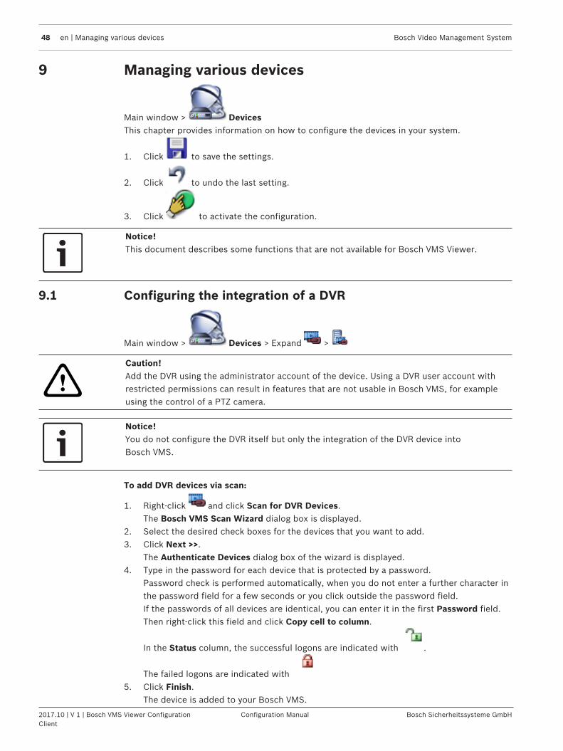
9 Managing various devices
Main window > DevicesThis chapter provides information on how to configure the devices in your system.
1. Click to save the settings.
2. Click to undo the last setting.
3. Click to activate the configuration.
Notice!This document describes some functions that are not available for Bosch VMS Viewer.
9.1 Configuring the integration of a DVR
Main window > Devices > Expand >
!
Caution!Add the DVR using the administrator account of the device. Using a DVR user account withrestricted permissions can result in features that are not usable in Bosch VMS, for exampleusing the control of a PTZ camera.
Notice!You do not configure the DVR itself but only the integration of the DVR device intoBosch VMS.
To add DVR devices via scan:
1. Right-click and click Scan for DVR Devices.The Bosch VMS Scan Wizard dialog box is displayed.
2. Select the desired check boxes for the devices that you want to add.3. Click Next >>.
The Authenticate Devices dialog box of the wizard is displayed.4. Type in the password for each device that is protected by a password.
Password check is performed automatically, when you do not enter a further character inthe password field for a few seconds or you click outside the password field.If the passwords of all devices are identical, you can enter it in the first Password field.Then right-click this field and click Copy cell to column.
In the Status column, the successful logons are indicated with .
The failed logons are indicated with 5. Click Finish.
The device is added to your Bosch VMS.

Bosch Video Management System Managing various devices | en 49
Bosch Sicherheitssysteme GmbH Configuration Manual 2017.10 | V 1 | Bosch VMS Viewer ConfigurationClient
To remove an item:1. Click the Settings tab, the Cameras tab, the Inputs tab, or the Relays tab.2. Right-click an item and click Remove. The item is removed.
Notice!To restore a removed item, right-click the DVR device and click Rescan DVR Device.
To rename a DVR device:1. Right-click a DVR device and click Rename.2. Type the new name for the item.
See also– Bosch VMS Scan Wizard, page 77– DVR (Digital Video Recorder) page, page 68
9.2 Adding a monitor wall
Main window > Devices > Right-click > Click Add Monitor Wall.After having added the monitor wall, the user of Operator Client can control this monitor wall.The user can change the monitor layout and assign encoders to monitors.To add:1. Select the desired decoder.2. If required, enter the maximum number of cameras and configure thumbnails.
3. Click .
4. Click Maps and Structure.5. Drag the monitor wall to the Logical Tree.6. If required, configure the access to the monitor wall with corresponding user group
permissions.
See also– Add Monitor Wall dialog box, page 76

50 en | Configuring the Logical Tree Bosch Video Management System
2017.10 | V 1 | Bosch VMS Viewer ConfigurationClient
Configuration Manual Bosch Sicherheitssysteme GmbH
10 Configuring the Logical TreeThis chapter provides information on how to configure the Logical Tree and how to manageresource files such as maps.
Notice!If you move a group of devices in the Logical Tree, these devices loose their permissionsettings. You must set the permissions in the User Groups page again.
1. Click to save the settings.
2. Click to undo the last setting.
3. Click to activate the configuration.
Notice!This document describes some functions that are not available for Bosch VMS Viewer.
See also– Sequence Builder dialog box, page 117– Add Sequence dialog box, page 118– Add Sequence Step dialog box, page 118
10.1 Configuring the Logical Tree
See also– Structure page, page 116
10.2 Adding a device to the Logical Tree
Main window > Maps and StructureTo add a device:4 Drag an item from the Device Tree to the required location in the Logical Tree.
You can drag a complete node with all sub-items from the Device Tree to the Logical Tree.You can select multiple devices by pressing the CTRL- or the SHIFT-key.
See also– Structure page, page 116
10.3 Removing a tree item
Main window > Maps and Structure

Bosch Video Management System Configuring the Logical Tree | en 51
Bosch Sicherheitssysteme GmbH Configuration Manual 2017.10 | V 1 | Bosch VMS Viewer ConfigurationClient
To remove a tree item from the Logical Tree:4 Right-click an item in the Logical Tree and click Remove. If the selected item has sub-
items, a message box is displayed. Click OK to confirm. The item is removed. When you remove an item from a map folder of the Logical Tree, it is also removed fromthe map.
See also– Structure page, page 116
10.4 Managing pre-configured camera sequences
Main window > Maps and StructureYou can perform the following tasks for managing camera sequences:– Create a camera sequence– Add a step with a new dwell time to an existing camera sequence– Remove a step from camera sequence– Delete a camera sequence
Notice!When the configuration is changed and activated, a camera sequence (pre-configured orautomatic) usually is continued after restart of the Operator Client.But in the following cases the sequence is not continued:A monitor where the sequence is configured to be displayed has been removed.The mode of a monitor (single/quad view) where the sequence is configured to be displayedhas been changed.The logical number of a monitor where the sequence is configured to be displayed ischanged.
Notice!After each of the following tasks:
Click to save the settings.
To create a camera sequence:1. In the Logical Tree, select a folder where you want to create the camera sequence.
2. Click .The Sequence Builder dialog box is displayed.
3. In the Sequence Builder dialog box, click .The Add Sequence dialog box is displayed.
4. Enter the appropriate values.For detailed information on the various fields, see the Online Help for the appropriateapplication window.4 Click OK.
A new camera sequence is added.To add a step with a new dwell time to a camera sequence:1. Select the desired camera sequence.

52 en | Configuring the Logical Tree Bosch Video Management System
2017.10 | V 1 | Bosch VMS Viewer ConfigurationClient
Configuration Manual Bosch Sicherheitssysteme GmbH
2. Click Add Step.The Add Sequence Step dialog box is displayed.
3. Make the appropriate settings.4. Click OK.
A new step is added to the camera sequence.To remove a step from a camera sequence:4 Right-click the desired camera sequence and click Remove Step.
The step with the highest number is removed.To delete a camera sequence:1. Select the desired camera sequence.
2. Click . The selected camera sequence is removed.
See also– Sequence Builder dialog box, page 117– Add Sequence dialog box, page 118– Add Sequence Step dialog box, page 118
10.5 Adding a camera sequence
Main window > Maps and StructureYou add a camera sequence to the root directory or to a folder of the Logical Tree.To add a camera sequence:1. In the Logical Tree, select a folder where you want to add the new camera sequence.
2. Click . The Sequence Builder dialog box is displayed.3. In the list, select a camera sequence.
4. Click Add to Logical Tree. A new is added under the selected folder.
See also– Sequence Builder dialog box, page 117
10.6 Adding a folder
Main window > Maps and StructureTo add a folder:1. Select a folder where you want to add the new folder.
2. Click . A new folder is added under the selected folder.
3. Click to rename the folder.4. Type the new name and press ENTER.
See also– Structure page, page 116

Bosch Video Management System Configuring cameras and recording settings | en 53
Bosch Sicherheitssysteme GmbH Configuration Manual 2017.10 | V 1 | Bosch VMS Viewer ConfigurationClient
11 Configuring cameras and recording settingsNotice!This document describes some functions that are not available for Bosch VMS Viewer.
Main window > Cameras and RecordingThis chapter provides information on how to configure the cameras in your Bosch VMS.You configure various camera properties and the recording settings.
1. Click to save the settings.
2. Click to undo the last setting.
3. Click to activate the configuration.
See also– Cameras page, page 119– PTZ/ROI Settings dialog box, page 122– COM1, page 102
11.1 Configuring PTZ port settings
Main window > Devices > Expand > Expand > Expand > >Interfaces tab > Periphery tabor
Main window > Devices > Expand > Expand > > Interfaces tab >Periphery tabor
Main window > Devices > > > Interfaces tab > Periphery tabYou can only configure port settings for an encoder where the control of the camera isavailable and activated.When the encoder or PTZ camera is exchanged, the port settings are not retained. You mustagain configure them.After a firmware update check the port settings.To configure the port settings of an encoder:4 Make the appropriate settings.
The settings are valid immediately after saving. You do not have to activate theconfiguration.
For detailed information on the various fields, see the Online Help for the appropriateapplication window.

54 en | Configuring cameras and recording settings Bosch Video Management System
2017.10 | V 1 | Bosch VMS Viewer ConfigurationClient
Configuration Manual Bosch Sicherheitssysteme GmbH
See also– Periphery page, page 102
11.2 Configuring PTZ camera settings
Main window > Cameras and Recording > First configure the port settings of your PTZ camera before you can configure the PTZ camerasettings. Otherwise the PTZ control is not working in this dialog box.You can remove menu items of the context menu displayed on a PTZ camera hot spot on amap.
To configure the control of a camera:1. In the Camera Table, select the required encoder.
2. To activate the control of a camera: In the column, select the check box.
3. Click the button.The dialog box for configuring PTZ settings is displayed.
4. Remove the prepositions that you do not want to be displayed as context menu items ona map.
5. Make the appropriate settings.6. Click OK.For detailed information on the various fields, follow the link to the appropriate applicationwindow below.
See also– PTZ/ROI Settings dialog box, page 122– Configuring PTZ port settings, page 53

Bosch Video Management System Configuring users, permissions and Enterprise Access | en 55
Bosch Sicherheitssysteme GmbH Configuration Manual 2017.10 | V 1 | Bosch VMS Viewer ConfigurationClient
12 Configuring users, permissions and Enterprise Access
Main window > User GroupsThis chapter provides information on how to configure user groups, Enterprise User Groupsand Enterprise Access. You make all settings per user group and not per user. A user can onlybe the member of one user group or Enterprise User Group.You cannot change the settings of a default user group.This user group has access to all the devices of the Full Logical Tree and is assigned theAlways schedule.For accessing the Windows user groups of a domain, LDAP user groups are used.
Notice!Enterprise User Groups and Enterprise Access are not available for Bosch VMS Viewer.
1. Click to save the settings.
2. Click to undo the last setting.
3. Click to activate the configuration.
Notice!This document describes some functions that are not available for Bosch VMS Viewer.
See also– New User Group/Enterprise User Group/Enterprise Account dialog box, page 124– User Group Properties page, page 125– User Properties page, page 126– Add New Dual Authorization Group dialog box, page 127– Logon Pair Properties page, page 128– Select User Groups dialog box, page 128– Camera Permissions page, page 129– Copy User Group Permissions dialog box, page 130– LDAP Server Settings dialog box, page 130– Logical Tree page, page 133– Operator Features page, page 133– User Interface page, page 134
12.1 Creating a user
Main window > User Groups > User Groups tabor

56 en | Configuring users, permissions and Enterprise Access Bosch Video Management System
2017.10 | V 1 | Bosch VMS Viewer ConfigurationClient
Configuration Manual Bosch Sicherheitssysteme GmbH
Main window > User Groups > Enterprise User Group tab
Notice!Enterprise User Groups and Enterprise Access are not available for Bosch VMS Viewer.
You create a user as a new member of an existing user group or Enterprise User Group.
Notice!A user who wants to operate a Bosch IntuiKey keyboard connected to a decoder, must have anumber-only user name and password. The user name can have maximum 3 numbers; thepassword can have maximum 6 numbers.
To create a user:
1. Select a group and click .A new user is added to the User Groups tree.
2. Right-click the new user and click Rename.3. Enter the desired name and press ENTER.4. On the User Properties page, enter the user name and the password.
See also– User Groups page, page 123
12.2 Creating a group or account
Main window > User Groups
Notice!Enterprise User Groups and Enterprise Access are not available for Bosch VMS Viewer.
You can create a standard user group, an Enterprise User Group or an Enterprise Account.For adapting the user group permissions to your requirements, create a new user group andchange its settings.
To create a group or account:1. Click the desired tab for the group or account that you want to add:
- User Groups- Enterprise User Group - Enterprise Access
2. Click .The appropriate dialog box is displayed.
3. Type in the name and a description.4. For an Enterprise Account enter a password and confirm this password.

Bosch Video Management System Configuring users, permissions and Enterprise Access | en 57
Bosch Sicherheitssysteme GmbH Configuration Manual 2017.10 | V 1 | Bosch VMS Viewer ConfigurationClient
5. Click OK.A new group or account is added to the corresponding tree.
For detailed information on the various fields, see the Online Help for the appropriateapplication window.
See also– User Group Properties page, page 125– New User Group/Enterprise User Group/Enterprise Account dialog box, page 124– Add New Dual Authorization Group dialog box, page 127
12.3 Creating a dual authorization group
Main window > User Groups > User Groups tab > > New Dual AuthorizationGroup dialog boxor
Main window > User Groups > Enterprise User Group tab > > New EnterpriseDual Authorization Group dialog box
Notice!Enterprise User Groups and Enterprise Access are not available for Bosch VMS Viewer.
You select two groups. The members of these groups are the members of the new dualauthorization group.You can configure dual authorization for user groups and for Enterprise User Groups.
To create:1. Type in a name and description.
2. Click .The appropriate dialog box is displayed.
3. Select a group in each list.It is possible to select the same group in the second list.
4. For each group, select Force dual authorization if required.When this check box is selected, each user of the first group can only log on togetherwith a user of the second group.When this check box is cleared, each user of the first group can log on alone but he onlyhas the access rights of his group.
Related Topics– Logon Pair Properties page, page 128– Add New Dual Authorization Group dialog box, page 127– Select User Groups dialog box, page 128

58 en | Configuring users, permissions and Enterprise Access Bosch Video Management System
2017.10 | V 1 | Bosch VMS Viewer ConfigurationClient
Configuration Manual Bosch Sicherheitssysteme GmbH
12.4 Configuring LDAP settings
Main window > User Groups > User Groups tab > > Operating Permissionstabor
Main window > User Groups > Enterprise User Group tab > > OperatingPermissions tab
Notice!Enterprise User Groups and Enterprise Access are not available for Bosch VMS Viewer.
Caution!Do not assign an LDAP group to different Bosch VMS user groups. This can result in notintended permissions for these users.
Notice!Type the search paths accurately. Wrong paths can make the search on an LDAP server veryslow.
You configure LDAP groups in standard user groups or Enterprise User Groups.
To configure LDAP settings:1. Click the User Group Properties tab.2. In the LDAP Properties field, make the appropriate settings.For detailed information on the various fields, see the Online Help for the appropriateapplication window.
12.5 Associating an LDAP group
Main window > User Groups > User Groups tab > > Operating Permissionstabor
Main window > User Groups > Enterprise User Group tab > > OperatingPermissions tabYou associate an LDAP group with a Bosch VMS user group to give the users of this LDAPgroup access to the Operator Client. The users of the LDAP group have the access rights ofthe user group where you configure the LDAP group.You probably need the help of the IT administrator who is responsible for the LDAP server.You configure LDAP groups in standard user groups or Enterprise User Groups.
To associate an LDAP group:1. Click the User Group Properties tab.

Bosch Video Management System Configuring users, permissions and Enterprise Access | en 59
Bosch Sicherheitssysteme GmbH Configuration Manual 2017.10 | V 1 | Bosch VMS Viewer ConfigurationClient
2. In the LDAP Properties field, click Settings.The LDAP Server Settings dialog box is displayed.
3. Enter the settings of your LDAP server and click OK.For detailed information on the various fields, see the Online Help for the appropriateapplication window.4 In the LDAP groups list, double-click an LDAP group.
This LDAP group is entered in the Associated LDAP group field.
12.6 Configuring operating permissions
Main window > User Groups > User Groups tab > > Operating Permissionstabor
Main window > User Groups > Enterprise User Group tab > > OperatingPermissions tab
Notice!Enterprise User Groups and Enterprise Access are not available for Bosch VMS Viewer.
You can configure operating permissions like Logbook access or user interface settings.You cannot change these settings for a default user group.You configure operating permissions in standard user groups or Enterprise User Groups.To configure operating permissions:1. Click the Operator Features tab.2. Select or clear the check boxes as appropriate.For detailed information on the various fields, see the Online Help for the appropriateapplication window.
See also– User Group Properties page, page 125– User Interface page, page 134– Operator Features page, page 133
12.7 Configuring permissions for Logical Tree
Main window > User Groups > User Groups tab > Device Permissions tabor
Main window > User Groups > Enterprise Access tab > Device Permissions tab

60 en | Configuring users, permissions and Enterprise Access Bosch Video Management System
2017.10 | V 1 | Bosch VMS Viewer ConfigurationClient
Configuration Manual Bosch Sicherheitssysteme GmbH
Notice!Enterprise User Groups and Enterprise Access are not available for Bosch VMS Viewer.
You can set the permissions for all devices of the Logical Tree independently.In an Enterprise System, these permissions are valid for the access of Enterprise User Groupusers to the devices of a local Management Server, controlled by Enterprise Accounts.After you have moved permitted devices to a folder that is not permitted for this user group,you must set the permissions for the folder to grant access to its devices.You cannot change these settings for a default user group.You configure device permissions in standard user groups or Enterprise Accounts.To configure permissions:1. In the User Groups tree, select a user group or account.2. Click the Logical Tree tab.3. Select or clear the check boxes as appropriate.
Selecting an item below a node, automatically selects the node.Selecting a node, automatically selects all items below.
For detailed information on the various fields, see the Online Help for the appropriateapplication window.
12.8 Configuring camera permissions
Main window > User Groups > User Groups tab > Device Permissions tabor
Main window > User Groups > Enterprise Access tab > Device Permissions tab
Notice!Enterprise User Groups and Enterprise Access are not available for Bosch VMS Viewer.
You can configure various permissions for cameras, e.g. PTZ control.You cannot change these settings for a default user group.You configure camera permissions in standard user groups or Enterprise Accounts.To configure camera permissions:1. In the User Groups tree, select a user group or account.2. Click the Camera Permissions tab.3. Select or clear the check boxes as appropriate.For detailed information on the various fields, see the Online Help for the appropriateapplication window.

Bosch Video Management System Managing configuration data | en 61
Bosch Sicherheitssysteme GmbH Configuration Manual 2017.10 | V 1 | Bosch VMS Viewer ConfigurationClient
13 Managing configuration dataMain windowYou must activate the current configuration to make it valid for the Management Server andOperator Client. The system reminds you to activate when exiting the Configuration Client.Every activated configuration is saved with the date and with a description if required.At every point in time you can restore a recently activated configuration. All configurationssaved in the meantime get lost.You can export the current configuration in a configuration file and import this file later. Thisrestores the exported configuration. All configurations saved in the meantime get lost.
1. Click to save the settings.
2. Click to undo the last setting.
3. Click to activate the configuration.
Notice!This document describes some functions that are not available for Bosch VMS Viewer.
13.1 Activating the working configurationMain windowYou activate the currently working configuration. The Operator Client uses the activatedconfiguration after the next start if the user accepted it. If the activation is enforced, all openinstances of the Operator Client in the network exit and start again. The user of eachOperator Client instance usually does not have to log on again.You can configure a delayed activation time. If you configure a delayed activation time, theworking configuration is not activated at once but at the time configured. If you configureanother activation time later (delayed or not does not matter), this time is active now. Thefirst configured activation time is removed.When you exit the Configuration Client the system reminds you to activate the current workingcopy of the configuration.You cannot activate a configuration that contains a device without password protection.
Notice!If the activation is enforced, each instance of Operator Client restarts when the configurationis activated. Avoid unnecessary activations. Perform activations preferably in the night orduring time periods with low activities.
Notice!If your system contains devices that are not protected by a password, you must secure thesedevices before you can activate. You can deactivate this password enforcement.

62 en | Managing configuration data Bosch Video Management System
2017.10 | V 1 | Bosch VMS Viewer ConfigurationClient
Configuration Manual Bosch Sicherheitssysteme GmbH
To activate the currently working configuration:
1. Click .The Activate Configuration dialog box is displayed. If your configuration contains devices that are not protected by a password, you cannotactivate. In this case the Protect Devices with Default Password... dialog box isdisplayed.Follow the instructions in this dialog box and click Apply.The Activate Configuration dialog box is displayed again.
2. If appropriate, enter a delayed activation time. By default, the present point in time isconfigured as activation time. If you do not change the delayed activation time, theactivation is performed immediately.If appropriate, click to check Force activation for all Operator Clients.
3. Type a description and click OK.The current configuration is activated.Each Operator Client workstation is instantly restarted, if connected to the network andthe activation is enforced. If a workstation is not connected, it is restarted as soon it isconnected again.If you configured a delayed activation time, the configuration will be activated later.
See also– Activate Configuration dialog box, page 65
13.2 Activating a configurationMain windowYou can activate a previous version of the configuration that you have saved earlier.To activate a configuration:1. On the System menu, click Activation Manager....
The Activation Manager dialog box is displayed.2. In the list, select the configuration you want to activate.3. Click Activate.
A message box is displayed.4. Click OK.
The Activate Configuration dialog box is displayed.5. If appropriate, click to check Force activation for all Operator Clients. Each
Operator Client workstation is automatically restarted to activate the new configuration.The user cannot refuse the new configuration.If Force activation for all Operator Clients is not checked, on each Operator Clientworkstation a dialog box appears for some seconds. The user can refuse or accept thenew configuration. The dialog box is closed after a few seconds without user interaction.In this case the new configuration is not accepted.
See also– Activate Configuration dialog box, page 65– Activation Manager dialog box, page 65
13.3 Exporting configuration dataMain window

Bosch Video Management System Managing configuration data | en 63
Bosch Sicherheitssysteme GmbH Configuration Manual 2017.10 | V 1 | Bosch VMS Viewer ConfigurationClient
You can export the device configuration data of Bosch VMS in a .zip file. This .zip file containsthe database file (Export.bvms) and the user data (.dat file).
You can use these files for restoring a system configuration that has been exported before onthe same (Enterprise) Management Server or for importing it on another (Enterprise)Management Server. The user data file cannot be imported but you can use it to manuallyrestore the user configuration.
To export configuration data:1. On the System menu, click Export Configuration....
The Export Configuration File dialog box is displayed.
Note: If your current working copy configuration is not activated ( is active), youexport this working copy and not the activated configuration.
2. Click Save.3. Enter a filename.
The current configuration is exported. A .zip file with database and user data is created.
See also– Importing configuration data, page 63
13.4 Importing configuration dataMain windowThe following use cases are covered:– Importing a configuration that has been exported (backup has been performed) before on
the same server– Importing a configuration template that has been prepared and exported on another
server– Importing the configuration of an earlier Bosch VMS version.You can only import a configuration if the latest changes of the current working copy are savedand activated.For importing the configuration data you need the appropriate password.You cannot import user data.
To import the configuration:1. On the System menu, click Import Configuration....
The Import Configuration File dialog box is displayed.2. Select the desired file for import and click Open.
The Import Configuration... dialog box is displayed.3. Enter the appropriate password and click OK.
The Configuration Client is restarted. You must logon again.The imported configuration is not activated but editable in Configuration Client.
Notice!If you want to continue editing the configuration that has been activated for yourManagement Server, perform a rollback in the Activate Configuration dialog box.
See also– Exporting configuration data, page 62

64 en | Managing configuration data Bosch Video Management System
2017.10 | V 1 | Bosch VMS Viewer ConfigurationClient
Configuration Manual Bosch Sicherheitssysteme GmbH
13.5 Checking the status of your encoders/decodersMain window > Hardware menu > Device Monitor... command > Device Monitor dialog boxYou can check the status of all activated encoders/decoders in the Device Tree.

Bosch Video Management System Global Configuration Client windows | en 65
Bosch Sicherheitssysteme GmbH Configuration Manual 2017.10 | V 1 | Bosch VMS Viewer ConfigurationClient
14 Global Configuration Client windowsThis chapter contains information on some basic application windows available in Bosch VMSConfiguration Client.
Notice!This document describes some functions that are not available for Bosch VMS Viewer.
14.1 Activation Manager dialog boxMain window > System menu > Activation Manager... commandAllows you to activate the current configuration or to rollback to a previous configuration.
ActivateClick to display the Activate Configuration dialog box.
See also– Activating the working configuration, page 61– Activating a configuration, page 62
14.2 Activate Configuration dialog box
Main window > Allows you to type a description for the working copy of the configuration to be activated.

66 en | Global Configuration Client windows Bosch Video Management System
2017.10 | V 1 | Bosch VMS Viewer ConfigurationClient
Configuration Manual Bosch Sicherheitssysteme GmbH
Set Delayed Activation timeClick to select a delayed activation time.
Force activation for all Operator ClientsIf checked, each Operator Client workstation is automatically restarted to activate the newconfiguration. The user cannot refuse the new configuration.If not checked, on each Operator Client workstation a dialog box appears for some seconds.The user can refuse or accept the new configuration. The dialog box is closed after a fewseconds without user interaction. In this case the new configuration is not accepted.
Configure RRAS service before ActivationOnly available if you have enabled the Enable Port Mapping option in the Remote AccessSettings dialog box.If checked, the RRAS Configuration dialog box is displayed before activation is performed.
See also– Activating the working configuration, page 61
14.3 License Manager dialog boxMain window > Tools menu > License Manager... commandAllows you to license the Bosch VMS package that you have ordered and to upgrade withadditional features.
Base PackagesDisplays the available base packages.
Type NumberDisplays the Commercial Type Number (CTN) of the selected package, feature or expansion.
StatusDisplays the licensing status if applicable.
Optional FeaturesDisplays the available features.
ExpansionDisplays the available expansions and their count. To change the count point right from acheck box and click the up or down arrow.
ActivateClick to display the License Activation dialog box.
Import Bundle InfoClick to import an XML file containing a Bundle Information that you received from Bosch.
Add New PackageClick to display a dialog box for selecting a new license file.
14.4 License Activation dialog boxMain window > Tools menu > License Manager... command > License Manager dialog box >Activate buttonAllows you to license the Bosch VMS packages that you have ordered and to upgrade withadditional packages.For obtaining the License Activation Key you must contact the Bosch Activation Center andspecify the desired package and the computer signature of the Management Server.Additionally you need the Authorization Number. This number is included in your software box.

Bosch Video Management System Global Configuration Client windows | en 67
Bosch Sicherheitssysteme GmbH Configuration Manual 2017.10 | V 1 | Bosch VMS Viewer ConfigurationClient
License Activation Key:Allows you to type the License Activation Key received from the Bosch Activation Center.
14.5 Options dialog boxMain window > Settings menu > Options... command
LanguageAllows you to configure the language of your Configuration Client. If you select Systemlanguage the language of your Windows installation is used.This setting is enabled after restarting Configuration Client.
Enforce automatic logoff of Configuration Client after this time of inactivityAllows you to configure the automatic logoff of Configuration Client. Configuration Client willlog off after the configured time period.Changes in the configuration pages of the following devices in the Devices page are not savedautomatically and are lost after inactivity logoff:– Encoders– Decoders– VRM devices– iSCSI devices– VSG devicesAll other pending configuration changes are saved automatically.Note: Changes in dialog boxes that were not confirmed by clicking OK, are not saved.
Allow multiple logons with the same user nameAllows you to configure that a user of Bosch VMS SDK, Bosch VMS Web Client, Bosch VMSMobile App, or Operator Client can perform multiple synchronous logons with the same username.
14.6 License Investigator dialog boxMain window > Tools menu > License Inspector... command > License Inspector dialog boxYou can check whether the number of installed Bosch VMS licenses exceeds the number ofpurchased licenses.

68 en | Devices page Bosch Video Management System
2017.10 | V 1 | Bosch VMS Viewer ConfigurationClient
Configuration Manual Bosch Sicherheitssysteme GmbH
15 Devices pageNotice!This document describes some functions that are not available for Bosch VMS Viewer.
Main window > DevicesDisplays the Device Tree and the configuration pages.The count of items below an entry is displayed in square brackets.Allows you to configure the available devices, such as mobile video services, ONVIF encoders,Bosch Video Streaming Gateway devices, encoders, decoders, VRMs, local storage encoders,analog matrices, or peripheral devices like ATM / POS bridges.Note:Devices are represented in a tree and grouped by the physical network structure and thedevice categories.Video sources like encoders are grouped under VRMs. Digital video recorders such as DiBosare listed separately.
IP Device ConfigurationClick to display the IP Device Configuration dialog box.
Type in a string and press the ENTER key to filter thedisplayed items. Only items containing the string and their corresponding parent items (onlyin trees) are displayed. The count of filtered items and the total count of items is provided. An
active filter is indicated by . Enclose strings with double quotes to find them exactly, forexample "Camera 1" exactly filters the cameras with this name, not camera 201.
To cancel filtering, click .4 Click a tree item to display the corresponding page.
15.1 Initial Device Scan dialog boxMain window > Hardware menu > Initial Device Scan... commandDisplays the devices which have duplicate IP addresses or a default IP address (192.168.0.1).Allows you to change such IP addresses and subnet masks.You must enter the correct subnet mask before changing an IP address.
15.2 DVR (Digital Video Recorder) page
Main window > Devices > > Displays the property pages of a selected DVR.Allows you to integrate a DVR into your system.4 Click a tab to display the corresponding property page.
Notice!You do not configure the DVR itself but only the integration of the DVR device intoBosch VMS.

Bosch Video Management System Devices page | en 69
Bosch Sicherheitssysteme GmbH Configuration Manual 2017.10 | V 1 | Bosch VMS Viewer ConfigurationClient
!
Caution!Add the DVR using the administrator account of the device. Using a DVR user account withrestricted permissions can result in features that are not usable in Bosch VMS, for exampleusing the control of a PTZ camera.
See also– Configuring the integration of a DVR, page 48
15.2.1 Add DVR dialog box
Main window > Devices > Expand > > Add DVR RecorderAllows you to manually add a DVR device.
Network address:Type the DNS name or the IP address of your DVR.
User name:Type the user name for connecting to the DVR.
Password:Type the password for connecting to the DVR.
Click below to get step-by-step instructions:– Adding a device
15.2.2 Settings tab
Main window > Devices > > > Settings tabDisplays the network settings of the DVR connected to your system. Allows you to change thesettings if required.
15.2.3 Cameras tab
Main window > Devices > > > Cameras tabDisplays all video channels of the DVR as cameras. Allows you to remove cameras.A video input that is disabled in a DVR device is displayed as an active camera in Bosch VMSbecause earlier recordings could exist for this input.
15.2.4 Inputs tab
Main window > Devices > > > Inputs tabDisplays all inputs of the DVR.Allows you to remove items.
15.2.5 Relays tab
Main window > Devices > > > Relays tabDisplays all relays of the DVR. Allows you to remove items.
15.3 Workstation page
Main window > Devices > Expand > Allows you to configure the following settings for a workstation:

70 en | Devices page Bosch Video Management System
2017.10 | V 1 | Bosch VMS Viewer ConfigurationClient
Configuration Manual Bosch Sicherheitssysteme GmbH
– Add a CCTV keyboard connected to a Bosch Video Management System workstation.– Assign a Command Script that is executed on startup of the workstation.– Select the default stream for live display.– Enable Forensic Search.– Assign analog monitor groups to a workstation.A workstation must have the Operator Client software installed.
To add a Bosch IntuiKey keyboard that is connected to a decoder, expand , click .
To assign an analog monitor group, configure such a group in > > .
15.3.1 Settings page
Main window > Devices > Expand > > Settings tabAllows you to configure a script that is executed when the Operator Client on the workstationis started.Allows you to configure TCP or UDP as transmission protocol used for all cameras that aredisplayed in Live Mode on your workstation.Allows you to configure which stream of an IP device is used for live display.Allows you to enable Forensic Search for this workstation.And you can configure the keyboard that is connected to this workstation.
Network address:Type the DNS name or the IP address of your workstation.
Startup script:Select the desired script that you want to be started when the workstation’s Operator Clientis started. You create or import such a script on the Events page.
Default camera protocol:Select the default transmission protocol used for all cameras that are assigned to the LogicalTree of this workstation.
Override settings from "Cameras and Recording" pageSelect the check box to enable selecting the desired stream for live view.Note: For DVR devices which offer more than 1 stream (for example DIVAR AN 3000/5000),the Live stream setting from this DVR is also changed here. Live stream settings for DVRdevices are not available on the Cameras and Recording page.
Live StreamSelect the desired stream for live view.When you select Image pane size optimized, the resolution of each displayed camera isautomatically adjusted to the size of the Image pane depending on the resolution of the usedmonitor. This is useful for displaying multiple cameras with a large resolution, for example 4Kultra HD cameras. Only cameras with streams whose resolution can be configuredindependently, can adjust the resolution to the Image pane. The user of Operator Client canchange the stream selection for each camera individually.
Use transcoded stream instead, if availableSelect the check box to enable the usage of a transcoded stream if available. This transcodedstream is used instead of the selected stream for live view.For a transcoded stream being available in Bosch VMS, either MVS must be installed or yourVRM computer offers a built-in hardware transcoder.

Bosch Video Management System Devices page | en 71
Bosch Sicherheitssysteme GmbH Configuration Manual 2017.10 | V 1 | Bosch VMS Viewer ConfigurationClient
When a camera is displayed in Live Mode then the default stream set for the workstation isused. If the camera has no stream 2 or the transcoding service (SW and HW) is not availablethen stream 1 will be used even though another setting is configured in the workstationsettings.
Enable Forensic SearchClick to enable Forensic Search for this workstation.
Use direct playback from storageSelect the check box to send the video stream directly from the storage device to thisworkstation. Now the stream is not sent via VRM. The workstation still needs connection tothe VRM to ensure correct playback.
Retrieve live video from Video Streaming Gateway instead of cameraDisplays the list of Video Streaming Gateway devices. Select the desired entries to enable thetransmission of video data via low bandwidth segments between the video source and thisworkstation.
Keyboard type:Select the type of the keyboard that is connected to your workstation.
PortSelect the COM port that is used to connect your keyboard.
Baudrate:Select the maximum rate, in bits per second (bps), that you want data to be transmittedthrough this port. Usually, this is set to the maximum rate supported by the computer ordevice you are communicating with.
Data bits:Displays the number of data bits you want to use for each character that is transmitted andreceived.
Stop bits:Displays the time between each character being transmitted (where time is measured in bits).
Parity:Displays the type of error checking you want to use for the selected port.
Port type:Displays the connection type that is used to connect the Bosch IntuiKey keyboard with theworkstation.
15.4 Decoders page
Main window > Devices > Expand > Allows you to add and configure decoders.See Bosch Encoder / Decoder page, page 82 for details.
Notice!If you want to use decoders in your system, make sure that all encoders use the samepassword for the user authorization level.
See also– Scanning for devices, page 29

72 en | Devices page Bosch Video Management System
2017.10 | V 1 | Bosch VMS Viewer ConfigurationClient
Configuration Manual Bosch Sicherheitssysteme GmbH
15.4.1 Add Encoder / Add Decoder dialog box
Main window > Devices > Expand > Expand > Right-click > ClickAdd Encoder > Add Encoder dialog boxor
Main window > Devices > Right-click > Click Add Encoder > Add Encoderdialog boxor
Main window > Devices > Right-click > Click Add Encoder > Add Encoderdialog boxor
Main window > Devices > Expand > Expand > Right-click > ClickAdd Encoder > Add Encoder dialog boxor
Main window > Devices > Expand > Right-click > Click Add Decoder >Add Encoder dialog boxAllows you to add an encoder or decoder manually. This is especially useful when you want toadd any Video IP device from Bosch (only for VRM).
IP address:Type in a valid IP address.
Encoder type: / Decoder type:For a device with known device type, select the appropriate entry. It is not necessary that thedevice is available in the network.If you want to add any Video IP device from Bosch, select <Auto Detect>. The device must beavailable in the network.
15.4.2 Edit Encoder / Edit Decoder dialog box
Main window > Devices > Expand > Expand > Expand > Right-click
> Click Edit Encoder > Edit Encoder dialog boxor
Main window > Devices > Expand > Right-click > Click Edit Encoder >Edit Encoder dialog boxor

Bosch Video Management System Devices page | en 73
Bosch Sicherheitssysteme GmbH Configuration Manual 2017.10 | V 1 | Bosch VMS Viewer ConfigurationClient
Main window > Devices > Expand > Right-click > Click Edit Encoder >Edit Encoder dialog boxor
Main window > Devices > Expand > Expand > Right-click > ClickEdit Encoder > Edit Encoder dialog boxor
Main window > Devices > Expand > Expand > Right-click > ClickEdit Decoder > Edit Decoder dialog box

74 en | Devices page Bosch Video Management System
2017.10 | V 1 | Bosch VMS Viewer ConfigurationClient
Configuration Manual Bosch Sicherheitssysteme GmbH
Allows you to check and update the device capabilities of a device. On opening this dialog boxthe device is connected. The password is checked and the device capabilities of this deviceare compared with the device capabilities stored in Bosch VMS.
NameDisplays the device name. When you add a Video IP device from Bosch, the device name isgenerated. If required change the entry.
Network address:Type in the network address of the device.
User nameDisplays the user name used for authenticating at the device.
PasswordType in the valid password for authenticating at the device.
Show passwordClick to enable that the entered password is displayed. Be careful that nobody can spy outthis password.
AuthenticateClick to authenticate at the device with the credentials entered above.
Secure connection (encryption)You can activate the encryption of live video transferred from an encoder to the followingdevices if HTTPS port 443 is configured on the encoder:– Operator Client computer– Management Server computer– Configuration Client computer– VRM computer– Decoder
Note:When activated, the user of Operator Client cannot switch a stream to UDP and to UDPmulticast.When activated, ANR does not work for the affected device.When activated, encoder replay does not work on encoders with firmware earlier than 6.30.
Device CapabilitiesYou can sort the displayed device capabilities per category or alphabetically.A message text informs you whether the detected device capabilities match the current devicecapabilities. Click OK to apply the changes of the device capabilities after an upgrade of the device.
See also– Encrypting live video, page 45– Updating the device capabilities, page 42
15.4.3 Enter password dialog box
Main window > Devices > Expand > Expand > > Right-click >Change password... command

Bosch Video Management System Devices page | en 75
Bosch Sicherheitssysteme GmbH Configuration Manual 2017.10 | V 1 | Bosch VMS Viewer ConfigurationClient
Main window > Devices > Expand > Right-click > Change password... >Enter password dialog box
Main window > Devices > Expand > Expand > Expand > Right-click
> Change password... command
Main window > Devices > > Right-click > Change password... command
Main window > Devices > > Right-click > Change password... commandA password prevents unauthorized access to the device. You can use different authorizationlevels to limit access.Proper password protection is only guaranteed when all higher authorization levels are alsoprotected with a password. Therefore, you must always start from the highest authorizationlevel when assigning passwords.You can define and change a password for each authorization level if you are logged into the“service” user account.The device has three authorization levels: service, user, and live.– service is the highest authorization level. Entering the correct password gives access to
all the functions and allows all configuration settings to be changed.– user is the middle authorization level. At this level you can operate the device, play back
recordings, and also control camera, for example, but you cannot change theconfiguration.
– live is the lowest authorization level. At this level you can only view the live video imageand switch between the different live image displays.
For a decoder the following authorization level replaces the live authorization level:– destination password (only available for decoders)
Used for access to an encoder.
See also– Changing the password of an encoder / decoder, page 44– Providing the destination password for a decoder, page 44
15.5 Monitor Wall page
Main window > Devices > Allows you to add a monitor wall application. This application allows for controlling themonitor wall hardware from within Operator Client. No server is involved in controlling themonitor wall. This ensures that the user of Operator Client is always able to control themonitor wall even if the Management Server is offline.
NameType in a display name for your monitor wall.

76 en | Devices page Bosch Video Management System
2017.10 | V 1 | Bosch VMS Viewer ConfigurationClient
Configuration Manual Bosch Sicherheitssysteme GmbH
MonitorSelect a monitor that is connected to a decoder.If you add a decoder that has 2 monitors connected, you must display the Edit Decoder dialogbox of the decoder and update the device capabilities of this decoder. For each monitor add afurther monitor wall.
Maximum number of cameras to connectType in the maximum number of cameras that are allowed to be displayed in the monitor wall.If you leave the field empty, the operator can display as many cameras as Image panes on themonitor wall layout are available.
Enable thumbnailsClick to check if you want to display a snapshot in Operator Client for each monitor. Thissnapshot is regularly updated.
Initial sequenceSelect a camera sequence for initial display on the monitor wall when the operator starts thismonitor wall.
Notice!When you delete a sequence in the Sequence Builder dialog box, this sequence isautomatically removed from the Initial sequence list of a monitor wall if configured there.
See also– Sequence Builder dialog box, page 117– Adding a monitor wall, page 49– Adding a monitor wall, page 49
15.5.1 Add Monitor Wall dialog box
Main window > Devices > Right-click > Click Add Monitor Wall.Add the required decoder to your Bosch VMS before you add the monitor wall.
NameType in a display name for your monitor wall.
MonitorSelect a monitor that is connected to a decoder.If you add a decoder that has 2 monitors connected, you must display the Edit Decoder dialogbox of the decoder and update the device capabilities of this decoder. For each monitor add afurther monitor wall.
Maximum number of cameras to connectType in the maximum number of cameras that are allowed to be displayed in the monitor wall.If you leave the field empty, the operator can display as many cameras as Image panes on themonitor wall layout are available.
Enable thumbnailsClick to check if you want to display a snapshot in Operator Client for each monitor. Thissnapshot is regularly updated.
Initial sequenceSelect a camera sequence for initial display on the monitor wall when the operator starts thismonitor wall.

Bosch Video Management System Devices page | en 77
Bosch Sicherheitssysteme GmbH Configuration Manual 2017.10 | V 1 | Bosch VMS Viewer ConfigurationClient
See also– Adding a monitor wall, page 49
15.6 Bosch VMS Scan Wizard
Main window > Devices > Expand > Right-click > Click Scan forEncoders > Bosch VMS Scan Wizard dialog box
Main window > Devices > Expand > Right-click > Click Scan for VideoStreaming Gateways > Bosch VMS Scan Wizard dialog box
Main window > Devices > Right-click > Click Scan for Live Only Encoders>Bosch VMS Scan Wizard dialog box
Main window > Devices > Right-click > Click Scan for Local Storage Encoders> Bosch VMS Scan Wizard dialog boxThis dialog box allows you to scan for available devices in your network, configure them andadd them to your system in one process.
UseClick to select a device for adding to the system.
Type (not available for VSG devices)Displays the type of the device.
Display NameDisplays the device name that was entered in the Device Tree.
Network AddressDisplays the IP address of the device.
User NameDisplays the user name that is configured on the device.
PasswordType in the password for authenticating with this device.
StatusDisplays the status of authentication.
: Succeeded
: Failed
Main window > Devices > Right-click > Click Scan for VRM Devices> BoschVMS Scan Wizard dialog box

78 en | Devices page Bosch Video Management System
2017.10 | V 1 | Bosch VMS Viewer ConfigurationClient
Configuration Manual Bosch Sicherheitssysteme GmbH
Notice!For configuring a Secondary VRM you must first install the appropriate software on thedesired computer. Run Setup.exe and select Secondary VRM.
Master VRMIn the list, select the desired entry.
User NameDisplays the user name that is configured on the VRM device.You can type in another user name if required.
See also– Scanning for VRM devices, page 36– Adding an encoder to a VRM pool, page 38– Adding a live only encoder, page 39– Adding a local storage encoder, page 40– Scanning for devices, page 29
15.7 VRM Devices page
Main window > Devices > Expand > Allows you to add and configure VRM devices. A VRM device needs at least an encoder, aniSCSI device, and a LUN assigned to the iSCSI device, and a storage pool. See the ReleaseNotes and the data sheet for current firmware versions.
15.7.1 Add VRM dialog box
Main window > Devices > Right-click > Click Add VRM > Add VRM dialog boxAllows you to add a VRM device. You can select the type of the device and enter thecredentials.You can effectively assign a Failover VRM to a Master VRM only when both are online and aresuccessfully authenticated. The passwords are then synchronized.
NameType in a display name for the device.
Network address / portType in the IP address of your device.
TypeSelect the desired device type.
User nameType in the user name for authentication.
PasswordType in the password for authentication.
Show passwordClick to enable that the password is visible.
TestClick to check whether the device is connected and authentication is successful.

Bosch Video Management System Devices page | en 79
Bosch Sicherheitssysteme GmbH Configuration Manual 2017.10 | V 1 | Bosch VMS Viewer ConfigurationClient
PropertiesIf required, change the port numbers for the HTTP port and for the HTTPS port. This is onlypossible when you add or edit a VRM that is not connected. If the VRM is connected, thevalues are retrieved and you cannot change them.The Master VRM table row shows the selected device if applicable.
See also– Adding a Primary VRM manually, page 37
15.8 Live Only page
Main window > Devices > Expand > Allows you to add and configure encoders used for live only. You can add Bosch encoders andONVIF network video transmitters.
See also– Adding a live only encoder, page 39– Scanning for devices, page 29– Bosch Encoder / Decoder page, page 82
15.9 Local Storage page
Main window > Devices > Expand > Allows you to add and configure encoders with local storage.
See also– Adding a local storage encoder, page 40– Bosch Encoder / Decoder page, page 82– Scanning for devices, page 29
15.10 Unmanaged Sites page
Main window > Devices > Expand Allows you to add or remove Unmanaged Sites items. Unmanaged site items containunmanaged network devices.
See also– Unmanaged site, page 13– Adding an unmanaged site, page 34– Importing unmanaged sites, page 34– Configuring the time zone, page 35

80 en | Devices page Bosch Video Management System
2017.10 | V 1 | Bosch VMS Viewer ConfigurationClient
Configuration Manual Bosch Sicherheitssysteme GmbH
15.10.1 Add Unmanaged Site dialog box
Main window > Devices > Expand > Right-click Add Unmanaged NetworkDevice command > Add Unmanaged Network Device dialog boxYou can add a video network device to the Unmanaged Sites item of the Device Tree.It is assumed that all unmanaged network devices of an unmanaged site are located in thesame time zone.
Site nameDisplays the name of the site that was entered during creation of this item.
DescriptionType in a description for this site.
Time zoneSelect the appropriate time zone for this unmanaged site.
15.10.2 Unmanaged Site page
Main window > Devices > Expand > You can add a video network device to the Unmanaged Sites item of the Device Tree.It is assumed that all unmanaged network devices of an unmanaged site are located in thesame time zone.
Site nameDisplays the name of the site that was entered during creation of this item.
DescriptionType in a description for this site.
Time zoneSelect the appropriate time zone for this unmanaged site.
15.10.3 Add Unmanaged Network Device dialog box
Main window > Devices > Right-click > Add Unmanaged Site command > AddUnmanaged Site dialog boxYou can add a video network device to the Unmanaged Sites item of the Device Tree.It is assumed that all unmanaged network devices of an unmanaged site are located in thesame time zone.
Device type:Select the entry that is applicable for this device.Available entries:– DIVAR AN / DVR– DIVAR IP 3000/7000 / Bosch VMS– Bosch IP camera / encoder
Network address:Type in an IP address.Note: If you use a SSH connection, enter the address in the following format:ssh://IP or servername:5322

Bosch Video Management System Devices page | en 81
Bosch Sicherheitssysteme GmbH Configuration Manual 2017.10 | V 1 | Bosch VMS Viewer ConfigurationClient
User name:Type in the valid user name for this network device if available. See Unmanaged site, page 13for details.
Password:Type in the valid password if available. See Unmanaged site, page 13 for details on usercredentials.
See also– Adding an unmanaged site, page 34– Unmanaged site, page 13
15.10.4 Unmanaged Network Device page
Main window > Devices > Expand > Expand > You can add a video network device to the Unmanaged Sites item of the Device Tree.It is assumed that all unmanaged network devices of an unmanaged site are located in thesame time zone.
Device type:Select the entry that is applicable for this device.Available entries:– DIVAR AN / DVR– DIVAR IP 3000/7000 / Bosch VMS– Bosch IP camera / encoder
Network address:Type in an IP address.Note: If you use a SSH connection, enter the address in the following format:ssh://IP or servername:5322
User name:Type in the valid user name for this network device if available. See Unmanaged site, page 13for details.
Password:Type in the valid password if available. See Unmanaged site, page 13 for details on usercredentials.

82 en | Bosch Encoder / Decoder page Bosch Video Management System
2017.10 | V 1 | Bosch VMS Viewer ConfigurationClient
Configuration Manual Bosch Sicherheitssysteme GmbH
16 Bosch Encoder / Decoder pageThe count of items below an entry is displayed in square brackets.
To configure an encoder / decoder:
Main window > Devices > Expand > Expand > Expand > or
Main window > Devices > Expand > Expand > Expand > or
Main window > Devices > Expand > or
Main window > Devices > Expand >
Main window > Devices > Expand > Expand > Most of the settings on the encoder / decoder pages are active immediately after you click
. If you click another tab without clicking and changes have occurred, twocorresponding message boxes are displayed. Confirm them both if you want to save.To change the passwords of an encoder right-click the device icon and click Changepassword....To display the device in a Web browser right-click the device icon and click Show Webpage inBrowser.
Note:Depending on the selected encoder or camera, not all pages described here are available foreach device. The wording used here for describing the field labels can deviate from yoursoftware.4 Click a tab to display the corresponding property page.
Notice!This document describes some functions that are not available for Bosch VMS Viewer.
See also– Scanning for devices, page 29– Configuring an encoder / decoder, page 41

Bosch Video Management System Bosch Encoder / Decoder page | en 83
Bosch Sicherheitssysteme GmbH Configuration Manual 2017.10 | V 1 | Bosch VMS Viewer ConfigurationClient
16.1 Enter password dialog box
Main window > Devices > Expand > Expand > > Right-click >Change password... command
Main window > Devices > Expand > Right-click > Change password... >Enter password dialog box
Main window > Devices > Expand > Expand > Expand > Right-click
> Change password... command
Main window > Devices > > Right-click > Change password... command
Main window > Devices > > Right-click > Change password... commandA password prevents unauthorized access to the device. You can use different authorizationlevels to limit access.Proper password protection is only guaranteed when all higher authorization levels are alsoprotected with a password. Therefore, you must always start from the highest authorizationlevel when assigning passwords.You can define and change a password for each authorization level if you are logged into the“service” user account.The device has three authorization levels: service, user, and live.– service is the highest authorization level. Entering the correct password gives access to
all the functions and allows all configuration settings to be changed.– user is the middle authorization level. At this level you can operate the device, play back
recordings, and also control camera, for example, but you cannot change theconfiguration.
– live is the lowest authorization level. At this level you can only view the live video imageand switch between the different live image displays.
For a decoder the following authorization level replaces the live authorization level:– destination password (only available for decoders)
Used for access to an encoder.
See also– Changing the password of an encoder / decoder, page 44– Providing the destination password for a decoder, page 44
16.2 Unit Access page
16.2.1 Identification / Camera identificationDevice nameType the name of the device.

84 en | Bosch Encoder / Decoder page Bosch Video Management System
2017.10 | V 1 | Bosch VMS Viewer ConfigurationClient
Configuration Manual Bosch Sicherheitssysteme GmbH
The name simplifies the management of multiple devices in large systems. The name is usedfor identification of a device. Use a name that makes it as easy as possible to identify itslocation.Do not use any special characters in the name. Special characters are not supported and maycause problems, e.g. with playback.
Click to update the name in the Device Tree.Each device should be assigned a unique identifier that can be entered here as an additionalmeans of identification.
Initiator nameDisplays the iSCSI initiator name. The initiator name is automatically displayed after aconnection is established.
Initiator extensionType your own text to make the unit easier to identify in large iSCSI systems. This text isadded to the initiator name, separated from it by a full stop.
16.2.2 Camera nameCameraType the name of the camera. Ensure that Camera 1 is allocated to Video Input 1, Camera 2 toVideo Input 2, etc.The camera name facilitates the identification of the remote camera location, for example incase of an alarm. Use a name that makes it as easy as possible to identify the location.Do not use any special characters in the name. Special characters are not supported and maycause problems, for example the play back of recordings. The settings on this page apply to allcamera inputs.
Click to update the name in the Device Tree.
16.2.3 Version informationHardware versionDisplays the version of the hardware.
Firmware versionDisplays the version of the firmware.
16.3 Date/Time pageDevice date format Device date Device timeIf there are multiple devices operating in your system or network, it is important tosynchronize their internal clocks. For example, it is only possible to identify and correctlyevaluate simultaneous recordings when all devices are operating on the same time.
1. Enter the current date. Since the device time is controlled by the internal clock, it is notnecessary to enter the day of the week – it is added automatically.
2. Enter the current time or click Sync to PC to apply the system time from your computerto the device.
Note:It is important that the date/time is correct for recording. An incorrect date/time setting couldprevent correct recording.

Bosch Video Management System Bosch Encoder / Decoder page | en 85
Bosch Sicherheitssysteme GmbH Configuration Manual 2017.10 | V 1 | Bosch VMS Viewer ConfigurationClient
Device time zoneSelect the time zone in which the system is located.Daylight saving timeSet by Bosch VMS Management Server.
Time server IP addressSet by Bosch VMS Management Server.
Time server typeSet by Bosch VMS Management Server. Default setting is SNTP.
16.4 Installer / Initialization menu
16.4.1 Application variantThe camera has a choice of application variants that set up the camera for optimumperformance in a specific environment. Select the application variant best suited to yourinstallation.The application variant must be selected before any other changes are made, as the camerareboots automatically and resets the factory defaults when the application variant is changed.
16.4.2 Base frame rateSelect the base frame rate for the camera.Note: Shutter times, frame rates, and the analog output (if present) are affected by this value.
16.4.3 Camera LEDDisable the Camera LED on the camera to switch it off.
16.4.4 Mirror imageSelect On to output a mirror image of the camera picture.
16.4.5 Flip imageSelect On to output an upside down camera image.
16.4.6 Menu buttonSelect Disabled to prevent access to the install wizard via the menu button on the cameraitself.
16.4.7 HeaterSelect Auto to let the camera determine when the heater should be switched on.
16.4.8 Reboot device
16.4.9 Factory defaultsClick Defaults to restore the factory defaults for the camera. A confirmation screen appears.Allow several seconds for the camera to optimize the picture after a reset.
16.4.10 Lens WizardClick Lens Wizard... to open a separate window which can be used to focus the camera lens(not for all cameras).
16.5 Privacy Masks pagePrivacy masking is used to block a specific area of a scene from being viewed. Four privacymask areas can be defined. The activated masked areas are filled with the selected pattern inlive view.

86 en | Bosch Encoder / Decoder page Bosch Video Management System
2017.10 | V 1 | Bosch VMS Viewer ConfigurationClient
Configuration Manual Bosch Sicherheitssysteme GmbH
1. Select the pattern to be used for all masks.2. Check the box of the mask you wish to activate.3. Use the mouse to define the area for each of the masks.
Notice!Draw the mask at 50% optical zoom or less for improved masking performance.Draw the mask 10% larger than the object to ensure that the mask completely covers theobject as the camera zooms in and out.
Active masksTo activate a mask, select the appropriate check box.
Privacy masksSelect the privacy mask number. The preview window displays a gray rectangle in the scene.
EnabledSelect the check box to activate the privacy mask. After saving, the content inside the privacymask is no longer visible in the preview. This area is blocked out from being viewing andrecording.
PatternPattern of the privacy mask.
Preview windowIf necessary, change the size of the privacy mask area and move it to the position you want.
16.6 Recording Management page
Active recordings are indicated by .Point to the icon. Detailed information about the active recordings are displayed.
Recordings manually managedThe recordings are managed locally on this encoder. All relevant settings must be carried outmanually. The encoder / IP camera acts as a live only device. It is not be removed from VRMautomatically.
Recording 1 managed by VRMThe recordings of this encoder are managed by the VRM system.
Dual VRMRecording 2 of this encoder is managed by a secondary VRM.
iSCSI Media tabClick to display the available iSCSI storage connected to this encoder.
Local Media tabClick to display the available local storage on this encoder.
AddClick to add a storage device to the list of managed storage media.
RemoveClick to remove a storage device from the list of managed storage media.
16.7 Recording preferences pageThe Recording preferences page is displayed for each encoder. This page only appears if adevice is assigned to a VRM system.

Bosch Video Management System Bosch Encoder / Decoder page | en 87
Bosch Sicherheitssysteme GmbH Configuration Manual 2017.10 | V 1 | Bosch VMS Viewer ConfigurationClient
Primary targetOnly visible if the Recording preferences mode list on the Pool page is set to Failover.Select the entry for the required target.
Secondary targetOnly visible if the Recording preferences mode list on the Pool page is set to Failover and ifthe Secondary target usage list is set to On.Select the entry for the required target for configuring failover mode.
16.8 Video Input pageCamera name stampingThis field sets the position of the camera name overlay. It can be displayed at the Top, at theBottom, or at a position of your choice that you can then specify using the Custom option. Orit can be set to Off for no overlay information.1. Select the desired option from the list.2. If you select the Custom option, additional fields are displayed where you can specify the
exact position (Position (XY)).3. In the Position (XY) fields, enter the values for the desired position.
LogoClick Choose File to select a file. Heed the restrictions for file format, logo size, and colordepth. Click Upload to load the file to the camera.If no logo is selected, Configuration displays the message, “No file chosen.”
Logo positionSelect the position for the logo on the OSD: To the left of the name, To the right of thename, or Logo only.Select Off (the default value) to disable logo positioning.
Time stampingThis field sets the position of the time overlay. It can be displayed at the Top, at the Bottom orat a position of your choice that you can then specify using the Custom option. Or it can beset to Off for no overlay information.1. Select the desired option from the list.2. If you select the Custom option, additional fields are displayed where you can specify the
exact position (Position (XY)).3. In the Position (XY) fields, enter the values for the desired position.If necessary, display milliseconds for Time stamping. This information can be useful forrecorded video images; however, it does increase the processor's computing time. Select Offif displaying milliseconds is not needed.
Alarm mode stampingSelect On to display a text message overlay in the image in the event of an alarm. It can bedisplayed at a position of your choice that you can then specify using the Custom option. Or itcan be set to Off for no overlay information.1. Select the desired option from the list.2. If you select the Custom option, additional fields are displayed where you can specify the
exact position (Position (XY)).3. In the Position (XY) fields, enter the values for the desired position.
Alarm messageEnter the message to be displayed in the image in the event of an alarm. The maximum textlength is 31 characters.Check this box to make transparent the stamp background on the image.

88 en | Bosch Encoder / Decoder page Bosch Video Management System
2017.10 | V 1 | Bosch VMS Viewer ConfigurationClient
Configuration Manual Bosch Sicherheitssysteme GmbH
Camera OSDSelect On to momentarily display camera response information, such as Digital Zoom, Irisopen/close, and Focus near/far overlays in the image. Select Off to display no information.1. Select the desired option from the list.2. Specify the exact position (Position (XY)).3. In the Position (XY) fields, enter the values for the desired position.
Title OSDOSD titles can be displayed at a position of your choice.Select On to display sector or pre-position title overlays continuously in the image. Select Momentary to display sector or pre-position title overlays for a few seconds.1. Select the desired option from the list.2. Specify the exact position (Position (XY)).3. In the Position (XY) fields, enter the values for the desired position.Select Off to deactivate the display of overlay information.Video authenticationSelect from the Video authentication drop-down box a method for verifying the integrity ofthe video.If you select Watermarking, all images are marked with an icon. The icon indicates if thesequence (live or saved) has been manipulated.If you want to add a digital signature to the transmitted video images to ensure their integrity,select one of the cryptographic algorithms for this signature.
Signature interval [s]For certain Video authentication modes, enter the interval (in seconds) between insertions ofthe digital signature.
See also– Managing the verification of authenticity, page 46
16.9 Picture settings - Scene modeA scene mode is a collection of image parameters that are set in the camera when thatparticular mode is selected (installer menu settings are excluded). Several pre-defined modesare available for typical scenarios. After a mode has been selected, additional changes can bemade through the user interface.
16.9.1 Current modeSelect the mode you wish to use from the drop-down menu.
16.9.2 Mode IDThe name of the selected mode is displayed.
16.9.3 Copy mode toSelect the mode from the drop-down menu to which you wish to copy the active mode.
16.9.4 Restore Mode DefaultsClick Restore Mode Defaults to restore the factory default modes. Confirm you decision.
16.9.5 Scene mode factory defaultsOutdoorThis mode covers most situations. It should be used in applications where the lighting changesfrom day to night. It takes into account sun highlights and street (sodium vapor) lighting.

Bosch Video Management System Bosch Encoder / Decoder page | en 89
Bosch Sicherheitssysteme GmbH Configuration Manual 2017.10 | V 1 | Bosch VMS Viewer ConfigurationClient
MotionThis mode is used for monitoring the traffic movement on roads or parking lots. It can also beused for industrial applications where fast moving objects are to be monitored. Motionartifacts are minimized. This mode should be optimized for a sharp and detailed picture incolor and black/white mode.
Low lightThis mode is optimized for sufficient details at low light. It requires more bandwidth and canintroduce motion judder.
BLCThis mode is optimized for scenes with people moving in front of a bright background.
IndoorThis mode is similar to the outdoor mode but it avoids the limitations imposed by the sun orstreet lighting.
VibrantThis mode has enhanced contrast, sharpness and saturation.
16.9.6 Scene mode factory defaultsOutdoorThis mode covers most situations. It should be used in applications where the lighting changesfrom day to night. It takes into account sun highlights and street (sodium vapor) lighting.
MotionThis mode is used for monitoring the traffic movement on roads or parking lots. It can also beused for industrial applications where fast moving objects are to be monitored. Motionartifacts are minimized. This mode should be optimized for a sharp and detailed picture incolor and black/white mode.
Low lightThis mode is optimized for sufficient details at low light. It requires more bandwidth and canintroduce motion judder.
IndoorThis mode is similar to the outdoor mode but it avoids the limitations imposed by the sun orstreet lighting.
VibrantThis mode has enhanced contrast, sharpness and saturation.
16.9.7 Scene mode factory defaultsIndoorThis mode is similar to the outdoor mode but it avoids the limitations imposed by the sun orstreet lighting.
OutdoorThis mode covers most situations. It should be used in applications where the lighting changesfrom day to night. It takes into account sun highlights and street (sodium vapor) lighting.
Low lightThis mode is optimized for sufficient details at low light. It requires more bandwidth and canintroduce motion judder.
Night-optimizedThis mode is optimized for sufficient details at low light. It requires more bandwidth and canintroduce motion judder.

90 en | Bosch Encoder / Decoder page Bosch Video Management System
2017.10 | V 1 | Bosch VMS Viewer ConfigurationClient
Configuration Manual Bosch Sicherheitssysteme GmbH
Low bit rateThis mode reduces the bitrate for installations with restricted network bandwidth and storage.
BLCThis mode is optimized for scenes with people moving in front of a bright background.
VibrantThis mode has enhanced contrast, sharpness and saturation.
Sports and gamingThis mode is for high-speed capture, and improved color rendition and sharpness.
MotionThis mode is used for monitoring the traffic movement on roads or parking lots. It can also beused for industrial applications where fast moving objects are to be monitored. Motionartifacts are minimized. This mode should be optimized for a sharp and detailed picture incolor and black/white mode.
TrafficThis mode is used for monitoring the traffic movement on roads or parking lots. It can also beused for industrial applications where fast moving objects are to be monitored. Motionartifacts are minimized. This mode should be optimized for a sharp and detailed picture incolor and black/white.
RetailThis mode has improved color rendition and sharpness with reduced bandwidth requirements.
16.10 Picture settings - ColorContrast (0...255)Adjust the contrast with the slider from 0 to 255.
Saturation (0...255)Adjust the color saturation with the slider from 0 to 255.
Brightness (0...255)Adjust the brightness with the slider from 0 to 255.
16.10.1 White balance– Indoor: Allows the camera to continually adjust for optimal color reproduction in an
indoor environment.– Outdoor: Allows the camera to continually adjust for optimal color reproduction in an
outdoor environment.– In Manual mode the Red, Green, and Blue gain can be manually set to a desired position.
HoldClick Hold to put ATW on hold and save the current color settings. The mode changes tomanual.
R-gainIn Manual white balance mode, adjust the red gain slider to offset the factory white pointalignment (reducing red introduces more cyan).
G-gainIn Manual white balance mode, adjust the green gain slider to offset the factory white pointalignment (reducing green introduces more magenta).
B-gainIn Manual white balance mode, adjust the blue gain slider to offset the factory white pointalignment (reducing blue introduces more yellow).

Bosch Video Management System Bosch Encoder / Decoder page | en 91
Bosch Sicherheitssysteme GmbH Configuration Manual 2017.10 | V 1 | Bosch VMS Viewer ConfigurationClient
Note:It is only necessary to change the white point offset for special scene conditions.
DefaultClick Default to set all video values to their factory setting.
16.10.2 White balance– Basic auto mode allows the camera to continually adjust for optimal color reproduction
using an average reflectance method. This is useful for indoor light sources and forcolored LED light illumination.
– Standard auto mode allows the camera to continually adjust for optimal colorreproduction in an environment with natural light sources.
– Sodium vapor auto mode allows the camera to continually adjust for optimal colorreproduction in an environment with sodium vapor light sources (street lighting).
– In Manual mode the Red, Green, and Blue gain can be manually set to a desired position.
HoldClick Hold to put ATW on hold and save the current color settings. The mode changes tomanual.
R-gainIn Manual white balance mode, adjust the red gain slider to offset the factory white pointalignment (reducing red introduces more cyan).
G-gainIn Manual white balance mode, adjust the green gain slider to offset the factory white pointalignment (reducing green introduces more magenta).
B-gainIn Manual white balance mode, adjust the blue gain slider to offset the factory white pointalignment (reducing blue introduces more yellow).
Note:It is only necessary to change the white point offset for special scene conditions.
DefaultClick Default to set all video values to their factory setting.
16.10.3 White balance– Standard auto mode allows the camera to continually adjust for optimal color
reproduction in an outdoor environment.– In Manual mode the Red, Green, and Blue gain can be manually set to a desired position.
HoldClick Hold to put ATW on hold and save the current color settings. The mode changes tomanual.
R-gainIn Manual white balance mode, adjust the red gain slider to offset the factory white pointalignment (reducing red introduces more cyan).
G-gainIn Manual white balance mode, adjust the green gain slider to offset the factory white pointalignment (reducing green introduces more magenta).
B-gainIn Manual white balance mode, adjust the blue gain slider to offset the factory white pointalignment (reducing blue introduces more yellow).

92 en | Bosch Encoder / Decoder page Bosch Video Management System
2017.10 | V 1 | Bosch VMS Viewer ConfigurationClient
Configuration Manual Bosch Sicherheitssysteme GmbH
Note:It is only necessary to change the white point offset for special scene conditions.
DefaultClick Default to set all video values to their factory setting.
16.10.4 White balance– Basic auto mode allows the camera to continually adjust for optimal color reproduction
using an average reflectance method. This is useful for indoor light sources and forcolored LED light illumination.
– Standard auto mode allows the camera to continually adjust for optimal colorreproduction in an environment with natural light sources.
– Sodium vapor auto mode allows the camera to continually adjust for optimal colorreproduction in an environment with sodium vapor light sources (street lighting).
– Dominant color auto mode takes into account any dominant color in the image (forexample, the green of a football pitch or of a gaming table) and uses this information toobtain a well balanced color reproduction.
– In Manual mode the Red, Green, and Blue gain can be manually set to a desired position.
HoldClick Hold to put ATW on hold and save the current color settings. The mode changes tomanual.
RGB-weighted white balanceIn an auto mode, RGB-weighted white balance can be switched On or Off. When On,additional fine tuning of the automatic color reproduction can be made with the R, G and Bweight sliders.
R-gainIn Manual white balance mode, adjust the red gain slider to offset the factory white pointalignment (reducing red introduces more cyan).
G-gainIn Manual white balance mode, adjust the green gain slider to offset the factory white pointalignment (reducing green introduces more magenta).
B-gainIn Manual white balance mode, adjust the blue gain slider to offset the factory white pointalignment (reducing blue introduces more yellow).
Note:It is only necessary to change the white point offset for special scene conditions.
DefaultClick Default to set all video values to their factory setting.
16.11 Picture settings - ALC
16.11.1 ALC modeSelect the mode for automatic light-level control:– Fluorescent 50 Hz– Fluorescent 60 Hz– Outdoor
16.11.2 ALC levelAdjust the video output level (-15 to 0 to +15).

Bosch Video Management System Bosch Encoder / Decoder page | en 93
Bosch Sicherheitssysteme GmbH Configuration Manual 2017.10 | V 1 | Bosch VMS Viewer ConfigurationClient
Select the range within which the ALC will operate. A positive value is more useful for low-light conditions; a negative value is more useful for very bright conditions.
16.11.3 Saturation (av-pk)The saturation (av-pk) slider configures the ALC level so that it controls mainly on sceneaverage level (slider position -15) or on scene peak level (slider position +15). Scene peaklevel is useful for capturing images that contain car headlights.
16.11.4 Exposure/frame rateAutomatic exposureSelect to let the camera automatically set the optimum shutter speed. The camera tries tomaintain the selected shutter speed as long as the light level of the scene permits.4 Select the minimum frame rate for automatic exposure. (The values available depend on
the value set for the Base frame rate in the Installer Menu.)
Fixed exposureSelect to set a fixed shutter speed.4 Select the shutter speed for fixed exposure. (The values available depend on the value set
for the ALC mode.)4 Select a default shutter speed. The default shutter improves the motion performance in
auto exposure mode.
16.11.5 Day/nightAuto - the camera switches the IR cut-off filter on and off depending on the scene illuminationlevel.Monochrome - the IR cut-off filter is removed, giving full IR sensitivity.Color - the camera always produces a color signal regardless of light levels.
Switch levelSet the video level at which the camera in Auto mode switches to monochrome operation (-15to 0 to +15).A low (negative) value means that the camera switches to monochrome at a lower light level. Ahigh (positive) value means that the camera switches to monochrome at a higher light level.
Note:To ensure stability when using IR illuminators, use the alarm interface for reliable Day/Nightswitching.
Switch levelSet the video level at which the camera in Auto mode switches to monochrome operation (-15to 0 to +15).A low (negative) value means that the camera switches to monochrome at a lower light level. Ahigh (positive) value means that the camera switches to monochrome at a higher light level.
IR function(only for cameras with built-in IR illuminators)Select the control setting for IR illumination:– Auto: the camera automatically switches the IR illumination.– On: the IR illumination is always on.– Off: the IR illumination is always off.
Intensity levelSet the intensity of the IR beam (0 to 30).

94 en | Bosch Encoder / Decoder page Bosch Video Management System
2017.10 | V 1 | Bosch VMS Viewer ConfigurationClient
Configuration Manual Bosch Sicherheitssysteme GmbH
Day-to-night switchoverAdjust the slider to set the video level at which the camera in Auto mode switches from colorto monochrome operation (-15 to +15).A low (negative) value means that the camera switches to monochrome at a lower light level. Ahigh (positive) value means that the camera switches to monochrome at a higher light level.
Night-to-day switchoverAdjust the slider to set the video level at which the camera in Auto mode switches frommonochrome to color operation (-15 to +15).A low (negative) value means that the camera switches to color at a lower light level. A high(positive) value means that the camera switches to color at a higher light level.(The actual switch-over point might change automatically to avoid instable switching.)
Note:To ensure stability when using IR illuminators, use the alarm interface for reliable Day/Nightswitching.
16.12 Encoder Regions page1. Select one of the eight available regions from the drop-down box.2. Use the mouse to define the area for that region by dragging the center or sides of the
shaded window.3. Select the encoder quality to be used for the defined area.
(Object and background quality levels are defined on the Expert Settings section of theEncoder Profile page.)
4. If required, select another region and repeat steps 2 and 3.5. Click Set to apply the region settings.
Preview
Click to open a viewing window where a 1:1 live image and the bit rate for the regionsettings can be previewed.
16.13 Camera pageAE-response speedSelect the speed of the response of auto exposure. Options are Super slow, Slow, Medium(default), Fast.
Backlight compensationOptimizes the video level for the selected area of the image. Parts outside this area may beunderexposed or overexposed. Select On to optimize the video level for the central area of theimage. The default setting is Off.
Blue GainThe blue gain adjustment offsets the factory white point alignment (reducing blue introducesmore yellow). It is only necessary to change the white point offset for special sceneconditions.
Color hueThe degree of color in the video image (HD only). Values range from -14° to 14°; the default is8°.
Fixed GainUse the slide to select the desired number for fixed gain. The default is 2.
Bosch Video Management System Bosch Encoder / Decoder page | en 95
Bosch Sicherheitssysteme GmbH Configuration Manual 2017.10 | V 1 | Bosch VMS Viewer ConfigurationClient
Gain controlAdjusts the automatic gain control (AGC). Automatically sets the gain to the lowest possiblevalue needed to maintain a good picture.– AGC (default): electronically brightens dark scenes, which may cause graininess in low
light scenes.– Fixed: no enhancement. This setting disables the Max. Gain Level option.
If you select this option, the camera makes the following changes automatically:– Night Mode: switches to Color– Auto Iris: switches to Constant
High sensitivityAdjusts the level of intensity or lux within the image. Select from Off or On.
Maximum Gain LevelControls the maximum value the gain can have during AGC operation. To set the maximumgain level, choose from:– Normal– Medium– High (default)
Night modeSelects night mode (B/W) to enhance lighting in low light scenes. Select from the followingoptions:– Monochrome: Forces the camera to stay in Nigh Mode and transmit monochrome images.– Color: The camera does not switch to Night Mode regardless of ambient light conditions.– Auto (default): The camera switches out of Night Mode after the ambient light level
reaches a pre-defined threshold.
Night mode thresholdAdjusts the level of light at which the camera automatically switches out of night mode (B/W)operation. Select a value between 10 and 55 (in increments of 5; default 30). The lower thevalue, the earlier the camera will switch to color mode.
Noise ReductionTurns on the 2D and 3D noise reduction feature.
Red GainThe red gain adjustment offsets the factory white point alignment (reducing red introducesmore cyan).
SaturationThe percentage of light or color in the video image. Values range from 60% to 200%; thedefault is 110%.
SharpnessAdjusts the sharpness of the picture. To set the sharpness, use the slider to select a number.The default is 12.
Current mode
ShutterAdjusts the electronic shutter speed (AES). Controls the time period for which light isgathered by the collecting device. The default setting is 1/60 second for NTSC and 1/50 forPAL cameras. The range of settings is from 1/1 to 1/10000.
Shutter Mode– Fixed: The shutter mode is fixed to a selectable shutter speed.

96 en | Bosch Encoder / Decoder page Bosch Video Management System
2017.10 | V 1 | Bosch VMS Viewer ConfigurationClient
Configuration Manual Bosch Sicherheitssysteme GmbH
– Automatic exposure: increases camera sensitivity by increasing the integration time onthe camera. This is accomplished by integrating the signal from a number of consecutivevideo frames to reduce signal noise.If you select this option, the camera disables Shutter automatically.
StabilizationThis feature is ideal for cameras mounted on a pole or mast, or on another location thatshakes frequently.Select On to activate the video stabilization feature (if available on your camera) that reducescamera shake in both the vertical and horizontal axis. The camera compensates for themovement of the image by up to 2% of the image size.Select Auto to activate the feature automatically when the camera detects vibration.Select Off to deactivate the feature.Note: This feature is not available on 20x models.
White BalanceAdjusts the color settings to maintain the quality of the white areas of the image.
16.13.1 ALCALC modeSelect the mode for automatic light-level control:– Fluorescent 50 Hz– Fluorescent 60 Hz– OutdoorALC levelAdjust the video output level (-15 to 0 to +15).Select the range within which the ALC will operate. A positive value is more useful for low-light conditions; a negative value is more useful for very bright conditions.The saturation (av-pk) slider configures the ALC level so that it controls mainly on sceneaverage level (slider position -15) or on scene peak level (slider position +15). Scene peaklevel is useful for capturing images that contain car headlights.Exposure
Automatic exposureSelect to let the camera automatically set the optimum shutter speed. The camera tries tomaintain the selected shutter speed as long as the light level of the scene permits.4 Select the minimum frame rate for automatic exposure. (The values available depend on
the value set for the Base frame rate in the Installer Menu.)
Fixed exposureSelect to set a fixed shutter speed.4 Select the shutter speed for fixed exposure. (The values available depend on the value set
for the ALC mode.)4 Select a default shutter speed. The default shutter improves the motion performance in
auto exposure mode.Day/nightAuto - the camera switches the IR cut-off filter on and off depending on the scene illuminationlevel.Monochrome - the IR cut-off filter is removed, giving full IR sensitivity.Color - the camera always produces a color signal regardless of light levels.
Note:To ensure stability when using IR illuminators, use the alarm interface for reliable Day/Nightswitching.
Bosch Video Management System Bosch Encoder / Decoder page | en 97
Bosch Sicherheitssysteme GmbH Configuration Manual 2017.10 | V 1 | Bosch VMS Viewer ConfigurationClient
Night-to-day switchoverAdjust the slider to set the video level at which the camera in Auto mode switches frommonochrome to color operation (-15 to +15).A low (negative) value means that the camera switches to color at a lower light level. A high(positive) value means that the camera switches to color at a higher light level.(The actual switch-over point might change automatically to avoid instable switching.)
Day-to-night switchoverAdjust the slider to set the video level at which the camera in Auto mode switches from colorto monochrome operation (-15 to +15).A low (negative) value means that the camera switches to monochrome at a lower light level. Ahigh (positive) value means that the camera switches to monochrome at a higher light level.
IR function(only for cameras with built-in IR illuminators)Select the control setting for IR illumination:– Auto: the camera automatically switches the IR illumination.– On: the IR illumination is always on.– Off: the IR illumination is always off.
Intensity levelSet the intensity of the IR beam (0 to 30).
16.13.2 Scene modeA scene mode is a collection of image parameters that are set in the camera when thatparticular mode is selected (installer menu settings are excluded). Several pre-defined modesare available for typical scenarios. After a mode has been selected, additional changes can bemade through the user interface.Current modeSelect the mode you wish to use from the drop-down menu.Mode IDThe name of the selected mode is displayed.
16.13.3 Scene Mode SchedulerThe scene mode scheduler is used to determine which scene mode should be used during theday and which scene mode should be used during the night.1. Select the mode you wish to use during the day from Marked range drop-down box.2. Select the mode you wish to use during the night from Unmarked range drop-down box.3. Use the two slider buttons to set the Time ranges.
OutdoorThis mode covers most situations. It should be used in applications where the lighting changesfrom day to night. It takes into account sun highlights and street (sodium vapor) lighting.
VibrantThis mode has enhanced contrast, sharpness and saturation.
MotionThis mode is used for monitoring the traffic movement on roads or parking lots. It can also beused for industrial applications where fast moving objects are to be monitored. Motionartifacts are minimized. This mode should be optimized for a sharp and detailed picture incolor and black/white mode.

98 en | Bosch Encoder / Decoder page Bosch Video Management System
2017.10 | V 1 | Bosch VMS Viewer ConfigurationClient
Configuration Manual Bosch Sicherheitssysteme GmbH
Low lightThis mode is optimized for sufficient details at low light. It requires more bandwidth and canintroduce motion judder.
IndoorThis mode is similar to the outdoor mode but it avoids the limitations imposed by the sun orstreet lighting.
BLCThis mode is optimized for scenes with people moving in front of a bright background.
16.13.4 WDRSelect Auto for automatic Wide Dynamic Range (WDR); select Off to disable WDR.
Note:WDR can only be active if Auto exposure is selected, and there is a match between the baseframe rate selected in the installer menu and the ALC fluorescent mode frequency. If there is aconflict, a pop-up window will suggest a solution and adjust the appropriate settings.
16.13.5 Sharpness levelThe slider adjusts the sharpness level between -15 and +15. Zero position of the slidercorresponds to the factory default level.A low (negative) value makes the picture less sharp. Increasing sharpness brings out moredetail. Extra sharpness can enhance the details of license plates, facial features and the edgesof certain surfaces but can increase bandwidth requirements.
16.13.6 Backlight CompensationSelect Off to switch off backlight compensation.Select On to capture details in high-contrast and extremely bright-dark conditions.Select to capture object detail in scenes with people moving in front of a bright background
16.13.7 Contrast enhancementSelect On to increase the contrast in low contrast conditions.
16.13.8 Intelligent DNRSelect On to activate intelligent Dynamic Noise Reduction (DNR) which reduces noise basedon motion and light levels.
Temporal noise filteringAdjusts the Temporal noise filtering level between -15 and +15. The higher the value, themore noise filtering.
Spatial noise filteringAdjusts the Spatial noise filtering level between -15 and +15. The higher the value, the morenoise filtering.
16.14 Lens page
16.14.1 FocusAutofocusContinuously adjusts the lens automatically to the correct focus for the sharpest picture.– One push (default): Activates the Auto Focus feature after the camera stops moving.
Once focused, Auto Focus is inactive until the camera is moved again.– Auto focus: Auto Focus is always active.

Bosch Video Management System Bosch Encoder / Decoder page | en 99
Bosch Sicherheitssysteme GmbH Configuration Manual 2017.10 | V 1 | Bosch VMS Viewer ConfigurationClient
– Manual: Auto Focus is inactive.
Focus polarity– Normal (default): Focus controls operate normally.– Reverse: Focus controls are reversed.
Focus speedControls how fast the Auto focus will readjust when the focus becomes blurred.
16.14.2 IrisAuto irisAutomatically adjusts the lens to allow the correct illumination of the camera sensor. This typeof lens is recommended for use when there are low light or changing light conditions.– Constant (default): Camera constantly adjusts to varying light conditions.
If you select this option, for example the AutoDome Junior HD makes the followingchanges automatically:– Gain control: switches to AGC– Shutter mode: switches to Normal
– Manual: Camera must be manually adjusted to compensate for varying light conditions.
Iris polarityCapability to reverse the operation of the iris button on the controller.– Normal (default): Iris controls operate normally.– Reverse: Iris controls are reversed.
Auto iris levelIncreases or decreases brightness according to the amount of light. Type a value between 1and 15, inclusive. The default setting is 8.
Iris speedControls how fast the Iris will adjust the opening according to the illumination of the scene.Type a value between 1 and 10, inclusive. The default setting is 5.
16.14.3 ZoomMaximum zoom speedControls the zoom speed. Default setting: Fast
Zoom polarityCapability to reverse the operation of the zoom button on the controller.– Normal (default): Zoom controls operate normally.– Reverse: Zoom controls are reversed.
Digital zoomDigital zoom is a method of decreasing (narrowing) the apparent angle of view of a digitalvideo image. It is accomplished electronically, without any adjustment of the camera's optics,and no optical resolution is gained in the process.– Off (default): Enables the Digital Zoom feature.– On: Disables the Digital Zoom feature.
16.15 PTZ pageAuto pan speedContinuously pans the camera at a speed between right and left limit settings. Type a valuebetween 1 and 60 (expressed in degrees), inclusive. The default setting is 30.

100 en | Bosch Encoder / Decoder page Bosch Video Management System
2017.10 | V 1 | Bosch VMS Viewer ConfigurationClient
Configuration Manual Bosch Sicherheitssysteme GmbH
InactivitySelects the time period the dome must be not controlled until the inactivity event will beexecuted.– Off (default): Camera remains on a current scene indefinitely.– Scene 1: Camera returns to Preset 1.– Previous Aux: Camera returns to the previous activity.
Inactivity periodDetermines the behavior of the dome when the control for dome is inactive. Select a timeperiod from the pull-down list (3 sec. - 10 min.). The default setting is 2 minutes.
Auto pivotThe Auto Pivot tilts the camera through the vertical position as the camera is rotated tomaintain the correct orientation of the image.Set the Auto Pivot to On (default) to automatically rotate the camera 180º when following asubject traveling directly beneath the camera. To disable this feature, click Off.
Freeze frameSelect On (default) to freeze the image while the camera moves to a predetermined sceneposition.
Tilt up limitClick Set, to set the upper tilt limit of the camera.
Tilt limitsClick Reset to clear the upper tilt limit.
16.16 Prepositions and Tours pageAllows you to define the individual scenes and a preposition tour comprised of the definedscenes.
To add scenes:
Click .
To delete scenes:
Select the scene, then click .
To overwrite (save) scenes:
Click .
To view scenes:
Select the scene, then click .
Include in standard tour (marked with *)Select the check box if the scene should be part of the preposition tour. The asterisk (*) onthe left of the scene name indicates this.
16.17 Sectors pageSectorThe pan capability (for example for the AutoDome Junior HD camera) is 360° and is dividedinto eight equal sectors. This allows you to apply a title for each sector and to designate anysectors as a Blanked Sector.To define a title for sectors:1. Place the pointer in the input box to the right of the sector number.2. Type a title for the sector, up to 20 characters long.3. To blank the sector, click the check box to the right of the sector title.

Bosch Video Management System Bosch Encoder / Decoder page | en 101
Bosch Sicherheitssysteme GmbH Configuration Manual 2017.10 | V 1 | Bosch VMS Viewer ConfigurationClient
16.18 Misc pageAddressAllows the appropriate device to be operated via the numerical address in the control system.Type a number between 0000 and 9999, inclusive, to identify the camera.
16.19 Logs pageThis page allows you to display and to save log files.
DownloadClick to obtain the log file information. The log files are displayed in the overview.
SaveClick to save the log files.
16.20 Audio pageThis function allows you to set the gain of the audio signals to suit your specific requirements.The current video image is shown in the small window next to the slide controls to help youcheck the selected audio source and improve assignments. Your changes are effectiveimmediately.The numbering of the audio inputs follows the labeling on the device and the assignment tothe respective video inputs. The assignment cannot be changed for Web browser connections.
AudioThe audio signals are sent in a separate data stream parallel to the video data, and so increasethe network load. The audio data are encoded according to G.711 and require an additionalbandwidth of approximately 80 kbps for each connection.– On: Transmits audio data.– Off: No transmission of audio data.
Line In 1 - Line In 4
Enter the value of the gain of the audio signal. Make sure that the display of the slider remains green.
Line Out
Enter the value of the gain. Make sure that the display of the slider remains green.
Microphone (MIC)Enter the value of the gain for the microphone.
Line Out/Speaker (SPK)Enter the value of the gain of the line and the loudspeaker.
Recording formatSelect a format for audio recording.G.711: default value.L16: Select L16 if you want better audio quality with higher sampling rates. This requiresapproximately eight times the G.711 bandwidth.
16.21 Relay pageThis function allows you to configure the switching behavior of the relay outputs.You can configure the switching behavior of the relay outputs. For each relay, you can specifyan open switch relay (normally closed contact) or a closed switch relay (normally opencontact).

102 en | Bosch Encoder / Decoder page Bosch Video Management System
2017.10 | V 1 | Bosch VMS Viewer ConfigurationClient
Configuration Manual Bosch Sicherheitssysteme GmbH
You can also specify whether an output should operate as a bistable or monostable relay. Inbistable mode, the triggered state of the relay is maintained. In monostable mode, you can setthe time after which the relay returns to the idle state.You can select different events that automatically activate an output. It is possible, forexample, to turn on a floodlight by triggering a motion alarm and then turning the light offagain when the alarm has stopped.
Idle stateSelect Open if you want the relay to operate as an NO contact, or select Closed if the relay isto operate as an NC contact.
Operating modeSelect an operating mode for the relay.For example, if you want an alarm-activated lamp to stay on after the alarm ends, select theBistable entry. If you wish an alarm-activated siren to sound for ten seconds, select the 10 sentry.
Relay followsIf required, select a specific event that will trigger the relay. The following events are possibletriggers:Off: Relay is not triggered by eventsConnection: Trigger whenever a connection is madeVideo alarm: Trigger by interruption of the video signal at the corresponding inputMotion alarm: Trigger by motion alarm at the corresponding input, as configured on the VCApage.Local input: Trigger by the corresponding external alarm inputRemote input: Trigger by remote station's corresponding switching contact (only if aconnection exists)
Note:The numbers in the lists of selectable events relate to the corresponding connections on thedevice, Video alarm 1, for example to the Video In 1 connection.
Trigger outputClick the relay button to trigger the relay manually (for example, for testing purposes or toactivate a door opener).The relay button displays the state of each relay.Red: Relay is activated.Blue: Relay is not activated.
16.22 Periphery page
16.22.1 COM1This function allows you to configure the serial interface parameters according to yourrequirements.If the device is working in multicast mode, the first remote location to establish a videoconnection to the device is also assigned the transparent data connection. However, afterabout 15 seconds of inactivity the data connection is automatically terminated and anotherremote location can exchange transparent data with the device.
Serial port functionSelect a controllable device from the list. Select Transparent data to transmit transparent datavia the serial port. Select Terminal to operate the device from a terminal.After selecting a device, the remaining parameters in the window are set automatically andshould not be changed.

Bosch Video Management System Bosch Encoder / Decoder page | en 103
Bosch Sicherheitssysteme GmbH Configuration Manual 2017.10 | V 1 | Bosch VMS Viewer ConfigurationClient
Baud rate (bps)Select the value for the transmission rate.
Stop bitsSelect the number of stop bits per character.
Parity checkSelect the type of parity check.
Interface modeSelect the protocol for the serial interface.
16.23 VCA pageThe device contains an integrated Video Content Analysis (VCA), which can detect and analyzechanges in the signal using image processing algorithms. Such changes are triggered bymotion in the camera's field of view.If there is not enough computing power, priority is given to live images and recordings. Thiscan lead to impairment of the VCA system. Observe the processor load and optimize thesettings of the device or the VCA settings, if necessary.You can configure profiles with different VCA configurations. You can save profiles on yourcomputer's hard drive and load saved profiles from there. This can be useful if you want totest a number of different configurations. Save a functioning configuration and test newsettings. You can use the saved configuration to restore the original settings at any time.4 Select a VCA profile and change the settings if necessary.
To rename the VCA profile:
4 Click . The Edit dialog box is displayed. Type the new name, and then click OK.
Alarm statusDisplays the current alarm state to check the effects of your settings immediately.
Aggregation time [s]Set an aggregation time of between 0 and 20 seconds. The aggregation time always startswhen an alarm event occurs. It extends the alarm event by the value set. This prevents alarmevents that occur in quick succession from triggering several alarms and successive events in arapid sequence. No further alarm is triggered during the aggregation time.The post-alarm time set for alarm recordings only starts once the aggregation time hasexpired.
Analysis typeSelect the required analysis type from the drop-down menu. Different analysis types offervarying levels of control over alarm rules, object filters and tracking modes.Refer to the VCA documentation for more information on using these.
Motion detectorSee Motion detector (MOTION+ only), page 104.Motion detection is available for the Motion+ analysis type. For the detector to function, thefollowing conditions must be met:– Analysis must be activated.– At least one sensor field must be activated.– The individual parameters must be configured to suit the operating environment and the
desired responses.– The sensitivity must be set to a value greater than zero.

104 en | Bosch Encoder / Decoder page Bosch Video Management System
2017.10 | V 1 | Bosch VMS Viewer ConfigurationClient
Configuration Manual Bosch Sicherheitssysteme GmbH
Note:Reflections of light (from glass surfaces, etc.), lights switching on and off, or changes in thelight level caused by cloud movement on a sunny day can trigger unintended responses fromthe motion detector and generate false alarms. Run a series of tests at different times of theday and night to ensure that the video sensor is operating as intended. For indoorsurveillance, ensure constant lighting of the areas during the day and at night.
Tamper detectionSee Tamper detection, page 105
Load...Click to load a saved profile. The Open dialog box is displayed. Select the filename of theprofile you want to load, and then click OK.
Save...Click to save the profile settings to another file. The Save dialog box is displayed. Type thefilename, select the folder where to save the file, and then click OK.
DefaultClick to return all settings to their default values.
16.23.1 Motion detector (MOTION+ only)Motion detectorFor the detector to function, the following conditions must be met:– Analysis must be activated.– At least one sensor field must be activated.– The individual parameters must be configured to suit the operating environment and the
desired responses.– The sensitivity must be set to a value greater than zero.
!
Caution!Reflections of light (off glass surfaces, etc.), switching lights on or off or changes in the lightlevel caused by cloud movement on a sunny day can trigger unintended responses from themotion detector and generate false alarms. Run a series of tests at different times of the dayand night to ensure that the video sensor is operating as intended.For indoor surveillance, ensure constant lighting of the areas during the day and at night.
Debounce time 1 sThe debounce time prevents very brief alarm events from triggering individual alarms. If theDebounce time 1 s option is activated, an alarm event must last at least 1 second to trigger analarm.
Selecting the areaSelect the areas of the image to be monitored by the motion detector. The video image issubdivided into square sensor fields. Activate or deactivate each of these fields individually. Toexclude particular regions of the camera's field of view from monitoring due to continuousmovement (by a tree in the wind, for example), the relevant fields can be deactivated.1. Click Mask... to configure the sensor fields. A new window opens.2. If necessary, click Clear All first to clear the current selection (fields marked red).3. Left-click the fields to be activated. Activated fields are marked red.4. If necessary, click Select All to select the entire video- frame for monitoring.5. Right-click any fields to deactivate.6. Click OK to save the configuration.

Bosch Video Management System Bosch Encoder / Decoder page | en 105
Bosch Sicherheitssysteme GmbH Configuration Manual 2017.10 | V 1 | Bosch VMS Viewer ConfigurationClient
7. Click the close button (X) in the window title bar to close the window without saving thechanges.
SensitivitySensitivity is available for the Motion+ analysis type. The basic sensitivity of the motiondetector can be adjusted for the environmental conditions to which the camera is subject. Thesensor reacts to variations in the brightness of the video image. The darker the observationarea, the higher the value that must be selected.
Minimum object sizeSpecify the number of sensor fields that a moving object must cover to generate an alarm.This setting prevents objects that are too small from triggering an alarm. A minimum value of 4is recommended. This value corresponds to four sensor fields.
16.23.2 Select Area dialog boxThis dialog box displays the camera image. Within this window you can activate the areas ofthe image to be monitored.
To activate an area:In the camera image, drag over the area you want to activate. Activated areas are markedyellow.
To deactivate an area:In the camera image, press the SHIFT key and click the area you want to deactivate.
To obtain commands in the window:To see the commands for activating or deactivating the areas, right-click anywhere in thewindow. The following commands are available:– Undo
Undoes the last command.– Set All
Activates the entire camera image.– Clear All
Deactivates the entire camera image.– Tool
Defines the shape of the mouse pointer.– Settings
Displays the Editor Settings dialog box. In this dialog box you can change the sensitivityand the minimum object size.
16.23.3 Tamper detectionYou can detect tampering of cameras and video cables by means of various options. Run aseries of tests at different times of the day and night to ensure that the video sensor isoperating as intended.The options for tamper detection can only be set for fixed cameras. Dome cameras or othermotorized cameras cannot be protected in this manner as the movement of the camera itselfcauses changes in the video image that are too great.
Scene too brightActivate this function if tampering associated with exposure to extreme light (for instance,shining a flashlight directly on the objective) should trigger an alarm. The average brightnessof the scene provides a basis for recognition.

106 en | Bosch Encoder / Decoder page Bosch Video Management System
2017.10 | V 1 | Bosch VMS Viewer ConfigurationClient
Configuration Manual Bosch Sicherheitssysteme GmbH
Global change (slider)Set how large the global change in the video image must be for an alarm to be triggered. Thissetting is independent of the sensor fields selected under Mask.... Set a high value if fewersensor fields need to change to trigger an alarm. With a low value, it is necessary for changesto occur simultaneously in a large number of sensor fields to trigger an alarm. This optionallows detection, independently of motion alarms, manipulation of the orientation or locationof a camera resulting from turning the camera mount bracket, for example.
Scene too darkActivate this function if tampering associated with covering the objective (for instance, byspraying paint on it) should trigger an alarm. The average brightness of the scene provides abasis for recognition.
Scene too noisyActivate this function if tampering associated with EMC interference (noisy scene as the resultof a strong interference signal in the vicinity of the video lines) should trigger an alarm.
Reference checkSave a reference image that can be continuously compared with the current video image. Ifthe current video image in the marked areas differs from the reference image, an alarm istriggered. This detects tampering that would otherwise not be detected, for example, if thecamera is turned.1. Click Reference to save the currently visible video image as a reference.2. Click Mask... and select the areas in the reference image that are to be monitored.3. Check the box Reference check to activate the on-going check. The stored reference
image is displayed in black and white below the current video image, and the selectedareas are marked in yellow.
4. Select the Disappearing edges or Appearing edges option to specify the reference checkonce again.
Trigger delay [s]Set delayed alarm triggering here. The alarm is only triggered after a set time interval inseconds has elapsed and then only if the triggering condition still exists. If the originalcondition has been restored before this time interval elapses, the alarm is not triggered. Thisavoids false alarms triggered by short-term changes, for example, cleaning activities in thedirect field of vision of the camera.
SensitivityThe basic sensitivity of the tamper detection can be adjusted for the environmental conditionsto which the camera is subject. The algorithm reacts to the differences between the referenceimage and the current video image. The darker the observation area, the higher the value thatmust be selected.
Appearing edgesSelect this option if the selected area of the reference image includes a largely homogenoussurface. If structures appear in this area, then an alarm is triggered.
Disappearing edgesThe area selected in the reference image should contain a prominent structure. If thisstructure is concealed or moved, the reference check triggers an alarm. If the selected area istoo homogenous, so that concealing and moving the structure would not trigger an alarm, thenan alarm is triggered immediately to indicate the inadequate reference image.
See also– Select Area dialog box, page 105

Bosch Video Management System Bosch Encoder / Decoder page | en 107
Bosch Sicherheitssysteme GmbH Configuration Manual 2017.10 | V 1 | Bosch VMS Viewer ConfigurationClient
16.24 Network Access pageThe settings on this page are used to integrate the device into an existing network.
DHCPIf the network has a DHCP server for the dynamic assignment of IP addresses, select On or Onplus Link-Local to automatically accept the DHCP-assigned IP address.If no DHCP server is available select On plus Link-Local to automatically assign a Link-Local(Auto-IP) address.For certain applications, the DHCP server must support the fixed assignment between IPaddress and MAC address, and must be appropriately set up so that, once an IP address isassigned, it is retained each time the system is rebooted.
Subnet maskEnter the appropriate subnet mask for the set IP address.
Gateway addressFor the device to establish a connection to a remote location in a different subnet, enter the IPaddress of the gateway here. Otherwise, this field can remain empty (0.0.0.0).
Prefix lengthEnter the appropriate prefix length for the set IP address.
DNS server addressThe device is easier to access if it is listed on a DNS server. For example, to establish anInternet connection to the camera, it is sufficient to enter the name given to the device on theDNS server as a URL in the browser. Enter the DNS server's IP address. Servers are supportedfor secure and dynamic DNS.
Video transmissionIf the device is used behind a firewall, TCP (Port 80) should be selected as the transmissionprotocol. For use in a local network, choose UDP.Multicast operation is only possible with the UDP protocol. The TCP protocol does notsupport multicast connections.
TCP rate controlActivate this option If you want to allow Adaptive Bit Rate encoding.
HTTP browser portSelect a different HTTP browser port from the list if required. The default HTTP port is 80. Tolimit connection to HTTPS, deactivate the HTTP port. To do this, activate the Off option.
HTTPS browser portTo limit browser access to encrypted connections, choose an HTTPS port from the list. Thestandard HTTPS port is 443. Select the Off option to deactivate HTTPS ports and limitconnections to unencrypted ports.The camera uses the TLS 1.0 protocol. Ensure that the browser has been configured tosupport this protocol. Also ensure that Java application support is activated (in the Java Plug-in Control Panel of the Windows Control Panel).To limit connections to SSL encryption, set the Off option in the HTTP browser port, the RCP+port, and Telnet support. This deactivates all unencrypted connections allowing connectionson the HTTPS port only.Configure and activate encryption for media data (video, audio, metadata) on the Encryptionpage.

108 en | Bosch Encoder / Decoder page Bosch Video Management System
2017.10 | V 1 | Bosch VMS Viewer ConfigurationClient
Configuration Manual Bosch Sicherheitssysteme GmbH
HSTSSelect On to use the web security policy HTTP Strict Transport Security (HSTS) to providesecure connections.
RCP+ port 1756Activating RCP+ port 1756 allows unencrypted connections on this port. To allow onlyencrypted connections, set the Off option to deactivate the port.
Telnet supportActivating Telnet support allows unencrypted connections on this port. To allow onlyencrypted connections, set the Off option to deactivate telnet support, making telnetconnections impossible.Interface mode ETH 1 - Interface mode ETH 2 - Interface mode ETH 3If necessary, select the Ethernet link type for interface ETH. Depending on the deviceconnected, it may be necessary to select a special operation type.
Network MSS [Byte]Set the maximum segment size for the IP packet's user data here. This gives the option toadjust the size of the data packets to the network environment and to optimize datatransmission. In UDP mode, comply with the MTU value set below.
iSCSI MSS [Byte]Enter the Maximum Segment Size (MSS) for a connection to the iSCSI system.The maximum segment size for a connection to the iSCSI system can be higher than for theother data traffic via the network. The size depends on the network structure. A higher value isonly useful if the iSCSI system is located in the same subnet as the device.
MAC addressDisplays the MAC address.
16.24.1 JPEG postingThis function allows you to save individual JPEG images on an FTP server at specific intervals.Then, retrieve these images at a later date to reconstruct alarm events, if required.
Image sizeSelect the resolution for the JPEG images.
File nameSelect how file names are created for the individual images that are transmitted.– Overwrite
The same file name is always used. An existing file is overwritten by the current file.– Increment
A number from 000 to 255 is added to the file name and automatically incremented by 1.When the number reaches 255, the number starts again from 000.
– Date/time suffixThe date and time are automatically added to the file name. Ensure that the date andtime of the device are always set correctly. For example, the file snap011008_114530.jpgwas stored on October 1, 2008 at 11.45 and 30 seconds.
Posting interval (s; 0 = Off)Enter the interval in seconds at which the images is sent to an FTP server. Enter zero for noimages to be sent.
16.24.2 FTP serverFTP server IP addressType the IP address of the FTP server on which to save the JPEG images.

Bosch Video Management System Bosch Encoder / Decoder page | en 109
Bosch Sicherheitssysteme GmbH Configuration Manual 2017.10 | V 1 | Bosch VMS Viewer ConfigurationClient
FTP server loginType your login name for the FTP server.
FTP server passwordType the password for the FTP server.
Path on FTP serverType the exact path where to save the images on the FTP server.
Post JPEG from cameraSelect the check box to activate the camera input for the JPEG image. The numbering followsthe labeling of the video inputs on the device.
Max. bit rateYou can limit the bit rate for FTP posting.
16.25 DynDNS
16.25.1 Enable DynDNSA dynamic Domain Name Service (DNS) allows you to select the unit via the Internet using ahost name, without having to know the current IP address of the unit. You can enable thisservice here. To do this, you must have an account with one of the dynamic DNS providers andyou must register the required host name for the unit on that site.
Note:For information about the service, registration process and available host names refer to theprovider.
16.25.2 ProviderSelect your dynamic DNS Provider from the drop-down list.
16.25.3 Host nameEnter the host name registered for the unit.
16.25.4 User nameEnter the user name you registered.
16.25.5 PasswordEnter the password you registered.
16.25.6 Force registration nowForce the registration by transferring the IP address to the DynDNS server. Entries that changefrequently are not provided in the Domain Name System. It is a good idea to force theregistration when setting up the device for the first time. Only use this function whennecessary and no more than once a day, to avoid the possibility of being blocked by theservice provider. To transfer the IP address of the device, click the Register button.
16.25.7 StatusThe status of the DynDNS function is displayed here for information purposes; these settingscannot be changed.

110 en | Bosch Encoder / Decoder page Bosch Video Management System
2017.10 | V 1 | Bosch VMS Viewer ConfigurationClient
Configuration Manual Bosch Sicherheitssysteme GmbH
16.26 Network Management
16.26.1 SNMPThe camera supports the SNMP V1 (Simple Network Management Protocol) for managing andmonitoring network components, and can send SNMP messages (traps) to IP addresses. Itsupports SNMP MIB II in the unified code.If On is selected for the SNMP parameter and a SNMP host address is not entered, the devicedoes not send the traps automatically and will only reply to SNMP requests. If one or twoSNMP host addresses are entered, SNMP traps are sent automatically. Select Off todeactivate the SNMP function.
SNMP host addressesTo send SNMP traps automatically, enter the IP address of one or two target devices here.
SNMP trapsTo choose which traps are sent:1. Click Select. A dialog box appears.2. Click the check boxes of the appropriate traps.3. Click Set to close the window and send all of the checked traps.
16.26.2 UPnPSelect On to activate UPnP communication. Select Off to deactivate it.When the Universal Plug-and-Play (UPnP) function is activated, the unit responds to requestsfrom the network and is automatically registered on the requesting computers as a newnetwork device. This function should not be used in large installations due to the large numberof registration notifications.
Note:To use the UPnP function on a Windows computer, both the Universal Plug-and-Play DeviceHost and the SSDP Discovery Service must be activated.
16.26.3 Quality of ServiceThe priority of the different data channels can be set by defining the DiffServ Code Point(DSCP). Enter a number between 0 and 252 as a multiple of four. For alarm video you can seta higher priority than for regular video and you can define a Post Alarm Time over which thispriority is maintained.
16.27 Advanced page
16.27.1 SNMPThe device supports the SNMP V2 (Simple Network Management Protocol) for managing andmonitoring network components, and can send SNMP messages (traps) to IP addresses. Thedevice supports SNMP MIB II in the unified code.
SNMPSelect On to activate the SNMP function.
1. SNMP host address / 2. SNMP host addressType the IP addresses of one or two target units. The device (for example encoder, camera)sends SNMP traps automatically to the target units.If you do not enter IP addresses, the device only replies to SNMP requests and does not sendSNMP traps to the target units.
SNMP trapsAllows you to select which traps the device sends to the target units. To do this, click Select.

Bosch Video Management System Bosch Encoder / Decoder page | en 111
Bosch Sicherheitssysteme GmbH Configuration Manual 2017.10 | V 1 | Bosch VMS Viewer ConfigurationClient
The SNMP traps dialog box is displayed.
SNMP traps dialog boxSelect the check boxes of the appropriate traps, and then click OK.
16.27.2 802.1xIEEE 802.1x allows you to communicate with the device if a RADIUS server is used in anetwork.
AuthenticationSelect On to activate 802.1x.
IdentityType the user name that the RADIUS server uses for identifying the device.
PasswordType the password that the RADIUS server uses for identifying the device.
16.27.3 RTSPRTSP portIf necessary, select a different port for the exchange of the RTSP data. The default port is 554.Off disables the RTSP function.
16.27.4 UPnPYou can activate the universal plug and play function (UPnP). When activated the camerareacts on requests from the network and will be registered automatically as a new networkdevice on the inquiring computers. The access to the camera is then possible using theWindows file explorer, and without knowledge of the camera’s IP address.
Note:In order to use the UPnP function on a computer with Windows XP or Windows Vista, theUniversal Plug and Play Device Host and the SSDP Discovery services must be activated.
16.27.5 TCP metadata inputThis feature allows a device to receive data from an external TCP sender, for example an ATMor POS device, and store it as metadata.
TCP portSelect the port for TCP communication. Select Off to deactivate the TCP metadata function.
Sender IP addressType the IP address of the TCP metadata sender here.
16.28 Multicast pageIn addition to a 1:1 connection between an encoder and a single receiver (unicast), the deviceenables multiple receivers to receive the video signal from an encoder simultaneously.The device either duplicates the data stream itself and then distributes it to multiple receivers(Multi-unicast) or it sends a single data stream to the network, where the data stream issimultaneously distributed to multiple receivers in a defined group (Multicast). You can enter adedicated multicast address and port for each stream.The prerequisite for multicast operation is a multicast-capable network that uses the UDP andIGMP protocols. Other group management protocols are not supported. The TCP protocoldoes not support multicast connections.

112 en | Bosch Encoder / Decoder page Bosch Video Management System
2017.10 | V 1 | Bosch VMS Viewer ConfigurationClient
Configuration Manual Bosch Sicherheitssysteme GmbH
A special IP address (class D address) must be configured for multicast operation in amulticast-enabled network. The network must support group IP addresses and the InternetGroup Management Protocol (IGMP V2). The address range is from 225.0.0.0 to239.255.255.255. The multicast address can be the same for multiple streams. However, it isthen necessary to use a different port in each case so that multiple data streams are not sentsimultaneously using the same port and the same multicast address.Note: The settings must be done for each encoder (video input) and for each streamindividually. The numbering follows the labeling of the video inputs on the device.
EnableTo enable simultaneous data reception on several receivers you need to activate the multicastfunction. To do this, select the check box. Then enter the multicast address.
Multicast AddressEnter a valid multicast address for each stream from the relevant encoder (video input) to beoperated in multicast mode (duplication of the data streams in the network).With the setting 0.0.0.0 the encoder for the relevant stream operates in multi-unicast mode(copying of data streams in the device). The device supports multi-unicast connections for upto five simultaneously connected receivers.Note: Duplication of data places a heavy demand on the device and can lead to impairment ofthe image quality under certain circumstances.
PortAssign a different port to each data stream if there are simultaneous data streams at the samemulticast address.Enter the port address of the required stream here.
StreamingSelect the check box to activate multicast streaming mode for the relevant stream. The deviceeven streams multicast data if no connection is active.For normal multicast operation, streaming is typically not required.
Packet TTL (only for Dinion IP, Gen4 and FlexiDome)Enter a value to specify how long the multicast data packets are active on the network. Ifmulticast is to be run via a router, the value must be greater than 1.
16.29 AccountsFour separate accounts can be defined for posting and recording export.
TypeSelect either FTP or Dropbox for the account type.Before using a Dropbox account ensure that the time settings of the device have beencorrectly synchronized.
Account nameEnter an account name to be shown as the target name.
FTP server IP addressFor an FTP server, enter the IP address.
FTP server loginEnter your login name for the account server.
FTP server passwordEnter the password that gives access to the account server. Click Check to confirm that it iscorrect.

Bosch Video Management System Bosch Encoder / Decoder page | en 113
Bosch Sicherheitssysteme GmbH Configuration Manual 2017.10 | V 1 | Bosch VMS Viewer ConfigurationClient
Path on FTP serverEnter an exact path to post the images on the account server. Click Browse... to browse to therequired path.
Maximum bit rateEnter the maximum bit rate in kbps that will be allowed when communicating with theaccount.
16.30 IP v4 Filter
To restrict the range of IP addresses within which you can actively connect to the device, fill-inan IP address and mask. Two ranges can be defined.4 Click Set and confirm to restrict access.
If either of these ranges are set, no IP V6 addresses are allowed to actively connect to thedevice.
The device itself may initiate a connection (for example, to send an alarm) outside the definedranges if it is configured to do so.
16.31 Licenses pageYou can enter the activation key to release additional functions or software modules.
Notice!The activation key cannot be deactivated again and is not transferable to other units.
16.32 Certificates pageHow to get here: Configuration window > expand System > click CertificatesThis page displays all available and used certificates. You can also create and upload newcertificates and delete certificates that are no longer needed.
Usage listDisplays all applications and their certificates that are used in the system. Trusted certificatesare .displayed separately.
Usage columnDisplays the application were certificates are needed.
Certificates/Trusted certificates columnFrom the list, select the certificate that belongs to the application in the Usage column.
SetClick to save your actions.
File listDisplays all certificates that are available in the system.
Name columnDisplays the file name of the certificate.
Type columnDisplays the type of the certificate.
Key columnDisplays that a key is available for the certificate.

114 en | Bosch Encoder / Decoder page Bosch Video Management System
2017.10 | V 1 | Bosch VMS Viewer ConfigurationClient
Configuration Manual Bosch Sicherheitssysteme GmbH
Common name columnDisplays the common name you must enter in case of generating a signing request to create anew certificate.
icon (Delete)Click to delete the selected certificate.
icon (Download)Click to download the certificate file.
AddClick to upload existing certificates or to generate a signing request to obtain new certificates.
16.33 Maintenance pageUpdate serverThe address of the firmware update server appears in the address box.
16.34 Decoder page
16.34.1 Decoder profileAllows you to set the various options for the display of video images on an analog monitor orVGA monitor.
Monitor nameType the name of the monitor. The monitor name facilitates the identification of the remotemonitor location. Use a name that makes it as easy as possible to identify the location.
Click to update the name in the Device Tree.
StandardSelect the video output signal of the monitor you are using. Eight pre-configured settings forthe VGA monitors are available in addition to the PAL and NTSC options for analog videomonitors.
Caution!Selecting a VGA setting with values outside the technical specification of the monitor canresult in severe damage to the monitor. Refer to the technical documentation of the monitoryou are using.
Window layoutSelect the default image layout for the monitor.
VGA screen sizeType the aspect ratio of the screen (for example 4 x 3) or the physical size of the screen inmillimeters. The device uses this information to accurately scale the video image fordistortion-free display.
16.34.2 Monitor displayThe device recognizes transmission interruptions and displays a warning on the monitor.
Display transmission disturbanceSelect On to display a warning in case of transmission interruption.
Disturbance sensitivityMove the slider to adjust the level of the interruption that triggers the warning.
Bosch Video Management System Bosch Encoder / Decoder page | en 115
Bosch Sicherheitssysteme GmbH Configuration Manual 2017.10 | V 1 | Bosch VMS Viewer ConfigurationClient
Disturbance notification textType the text of the warning the monitor displays when connection is lost. The maximum textlength is 31 characters.
Delete decoder logoClick to delete the logo that has been configured on the Web page of the decoder.

116 en | Structure page Bosch Video Management System
2017.10 | V 1 | Bosch VMS Viewer ConfigurationClient
Configuration Manual Bosch Sicherheitssysteme GmbH
17 Structure pageThe count of items below an entry is displayed in square brackets.
Main window > Maps and StructurePermissions can get lost. If you move a group of devices, these devices loose their permissionsettings. You must set the permissions on the User Groups page again.Displays the Device Tree, the Logical Tree, and the map window.Allows you to introduce a structure for all the devices in your Bosch VMS. Your structure isdisplayed in the Logical Tree.Allows you to perform the following tasks:– Configuring the Full Logical Tree– Managing resource files, assigning them to nodes– Creating hot spots on a map– Creating a malfunction relayResource files can be:– Site map files– Document files– Web files– Audio files– Command Scripts– Camera sequence filesHot spots can be:– Cameras– Inputs– Relays– Command Scripts– Sequences– Links to other maps
Displays a dialog box for managing resource files.
Displays a dialog box for adding or managing Command Scripts to the Logical Tree.
Displays a dialog box for adding or editing a camera sequence file.
Creates a folder in the Logical Tree.
Displays a dialog box for adding map resource files.
Displays a dialog box for adding a document file (HTML, HTM, TXT, URL, MHT).
Displays a dialog box for adding a link to an external application.
Displays a dialog box for adding a malfunction relay.
: Device was added to the Logical Tree.

Bosch Video Management System Structure page | en 117
Bosch Sicherheitssysteme GmbH Configuration Manual 2017.10 | V 1 | Bosch VMS Viewer ConfigurationClient
Type in a string and press the ENTER key to filter thedisplayed items. Only items containing the string and their corresponding parent items (onlyin trees) are displayed. The count of filtered items and the total count of items is provided. An
active filter is indicated by . Enclose strings with double quotes to find them exactly, forexample "Camera 1" exactly filters the cameras with this name, not camera 201.
To cancel filtering, click .
Notice!This document describes some functions that are not available for Bosch VMS Viewer.
17.1 Sequence Builder dialog box
Main window > Maps and Structure > Allows you to manage camera sequences.
Click to display the Add Sequence dialog box.
Click to rename a camera sequence.
Click to remove the selected camera sequence.
Notice!When you delete a sequence in the Sequence Builder dialog box, this sequence isautomatically removed from the Initial sequence list of a monitor wall if configured there.
Add StepClick to display the Add Sequence Step dialog box.
Remove StepClick to remove selected steps.
StepDisplays the number of the step. All cameras of a particular step have the same dwell time.
DwellAllows you to change the dwell time (seconds).
Camera NumberClick a cell to select a camera via its logical number.
CameraClick a cell to select a camera via its name.
Camera FunctionClick a cell to change the function of the camera in this row.
DataType the time for the duration of the selected camera function. To configure this, you musthave selected an entry in the Camera column and an entry in the Camera Function column.

118 en | Structure page Bosch Video Management System
2017.10 | V 1 | Bosch VMS Viewer ConfigurationClient
Configuration Manual Bosch Sicherheitssysteme GmbH
Data UnitSelect the unit for the selected time, for example seconds. To configure this, you must haveselected an entry in the Camera column and an entry in the Camera Function column.
Add to Logical TreeClick to add the selected camera sequence to the Logical Tree and to close the dialog box.
See also– Monitor Wall page, page 75– Managing pre-configured camera sequences, page 51
17.2 Add Sequence dialog box
Main window > Maps and Structure > > Sequence Builder dialog box > Allows you to configure the properties of a camera sequence.
Sequence name:Type an appropriate name for the new camera sequence.
Logical number:For using with a Bosch IntuiKey keyboard, enter a logical number for the sequence.
Dwell time:Enter the appropriate dwell time.
Cameras per step:Enter the number of cameras in each step.
Steps:Enter the appropriate number of steps.
See also– Managing pre-configured camera sequences, page 51
17.3 Add Sequence Step dialog box
Main window > Maps and Structure > > Add Step buttonAllows you to add a step with a new dwell time to an existing camera sequence.
Dwell time:Enter the appropriate dwell time.
See also– Managing pre-configured camera sequences, page 51

Bosch Video Management System Cameras and Recording page | en 119
Bosch Sicherheitssysteme GmbH Configuration Manual 2017.10 | V 1 | Bosch VMS Viewer ConfigurationClient
18 Cameras and Recording pageNotice!This document describes some functions that are not available for Bosch VMS Viewer.
Main window > Cameras and RecordingDisplays the Camera Table page or a Recording Table page.Allows you to configure camera properties and recording settings.Allows you to filter the cameras that are displayed according to their type.
Click to copy recording settings from one Recording Schedule to another.
Click to display the Stream Quality Settings dialog box.
Click to display the Scheduled Recording Settings dialog box.
Click to display the dialog box for configuring a selected PTZ camera.
Displays all available cameras regardless of their storage device.
Click to change the Camera Table according to the selected storage device.
Displays the corresponding Camera Table. No recording settingsare available because these cameras are not recorded in Bosch VMS.
Type in a string and press the ENTER key to filter thedisplayed items. Only items containing the string and their corresponding parent items (onlyin trees) are displayed. The count of filtered items and the total count of items is provided. An
active filter is indicated by . Enclose strings with double quotes to find them exactly, forexample "Camera 1" exactly filters the cameras with this name, not camera 201.
To cancel filtering, click .
18.1 Cameras page
Main window > Cameras and Recording > Click an icon to change the Cameras page
according to the desired storage device, for example Displays various information on the cameras available in your Bosch VMS.Allows you to change the following camera properties:– Camera name– Assignment of an audio source– Logical number– PTZ control, if available– Live quality (VRM and Live / Local Storage)

120 en | Cameras and Recording page Bosch Video Management System
2017.10 | V 1 | Bosch VMS Viewer ConfigurationClient
Configuration Manual Bosch Sicherheitssysteme GmbH
– Recording settings profile– Minimum and maximum storage time– Region of Interest (ROI)– Automated Network Replenishment– Dual Recording4 Click a column title to sort the table by this column.
Camera - EncoderDisplays the device type.
Camera - CameraDisplays the name of the camera.
Camera - Network AddressDisplays the IP address of the camera.
Camera - LocationDisplays the location of the camera. If the camera is not assigned to a Logical Tree yet,Unassigned Location is displayed.
Camera - PlatformDisplays the platform name of this encoder.
Camera - Device FamilyDisplays the name of the device family to which the selected camera belongs.
Camera - NumberClick a cell to edit the logical number that the camera received automatically when it wasdetected. If you enter an already used number, a corresponding error message is displayed.The logical number is "free" again when the camera is removed.
AudioClick a cell to assign an audio source to the camera.If an alarm occurs with low priority and with a camera that has audio configured, this audiosignal is played even when an alarm with higher priority is currently being displayed. But thisis only true, if the high priority alarm has no audio configured.
Stream 1 - Codec / Stream 2 - Codec (only VRM and Local Storage)Click a cell to select the desired codec for encoding the stream.
Stream 1 - Quality / Stream 2 - QualitySelect the desired quality of the stream used for live or recording. You configure qualitysettings in the Stream Quality Settings dialog box.
Live Video - Stream (only VRM and Live Only and Local Storage)Click a cell to select the stream for a VRM or a local storage / live only encoder.
Live Video - Profile (only available for ONVIF cameras)Click a cell to browse for the available live profile tokens of this ONVIF camera.If you select the <Automatic> entry, the stream with the highest quality is automatically used.
Live Video - ROIClick to enable Region of Interest (ROI). This is only possible if in the Quality column theH.264 MP SD ROI or H.265 MP SD ROI item is selected for stream 2 and stream 2 is assignedto Live Video.Note: If stream 1 is used for Live for a specific workstation then the Operator Client runningon this workstation cannot enable ROI for this camera.
is automatically enabled in the table.

Bosch Video Management System Cameras and Recording page | en 121
Bosch Sicherheitssysteme GmbH Configuration Manual 2017.10 | V 1 | Bosch VMS Viewer ConfigurationClient
Recording - SettingClick a cell to select the required recording setting. You configure the available recordingsettings in the Scheduled Recording Settings dialog box.
Recording - Profile (only available for ONVIF cameras)Click a cell to browse for the available recording profile tokens of this ONVIF camera. Selectthe desired entry.
Recording - ANRSelect a check box to enable the ANR function. You can only enable this function, if theencoder has an appropriate firmware version and an appropriate device type.
Recording - Max Pre-Alarm DurationDisplays the calculated maximum pre-alarm duration for this camera. This value can help youin calculating the required storage capacity of the local storage medium.
Notice!If a Mirrored VRM is already configured for an encoder, you cannot change any settings forthis encoder in the Secondary Recording columns.
Secondary Recording - Setting (only available if a Secondary VRM is configured)Click a cell to assign a scheduled recording setting to the dual recording of this encoder.Depending on your configuration it can happen that the configured stream quality forsecondary recording is not valid. The stream quality configured for primary recording is thenused instead.
Secondary Recording - Profile (only available for ONVIF cameras)Click a cell to browse for available recording profile tokens of this ONVIF camera.
(Only visible when you click All)Select a check box to activate PTZ control.
Note:For port settings refer to COM1, page 102.
Port (Only visible when you click All)Click a cell to specify which encoder serial port is used for PTZ control. For a PTZ cameraconnected to a Bosch Allegiant system, you can select Allegiant. For such a camera you do notneed to use a trunk line.
Protocol (Only visible when you click All)Click a cell to select the appropriate protocol for the PTZ control.
PTZ Address (Only visible when you click All)Type the address number for the PTZ control.
Recording - Storage Min Time [days] Secondary Recording - Storage Min Time [days] (only VRM and Local Storage)Click a cell to edit the minimum number of days that video data from this camera is retained.Recordings younger than this number of days are not deleted automatically.
Recording - Storage Max Time [days] Secondary Recording - Storage Max Time [days] (only VRM and Local Storage)Click a cell to edit the maximum number of days that video data from this camera is retained.Only recordings older than this number of days are deleted automatically. 0 = unlimited.

122 en | Cameras and Recording page Bosch Video Management System
2017.10 | V 1 | Bosch VMS Viewer ConfigurationClient
Configuration Manual Bosch Sicherheitssysteme GmbH
See also– Configuring PTZ camera settings, page 54– Configuring PTZ port settings, page 53
18.2 PTZ/ROI Settings dialog box
Main window > Cameras and Recording > > Select a PTZ camera > Allows you to configure a PTZ camera or a ROI camera.For a ROI camera no auxiliary commands are available.
Note:First configure the port settings of your PTZ camera before you can configure the PTZ camerasettings. Otherwise the PTZ control is not working in this dialog box.
Click to move the camera to the predefined position or to execute the command.
Click to save the predefined position or command.
Click to rename the predefined position or command.
Click to remove the predefined position or command.
Predefined Positions tabClick to display the table with the predefined positions.
NrDisplays the number of the predefined position.
NameClick a cell to edit the name of the predefined position.
Aux Commands tab (only for PTZ cameras)Click to display the table with the auxiliary commands.
NrDisplays the number of the auxiliary command.
NameClick a cell to edit the name of the command.
CodeClick a cell to edit the command´s code.
See also– Configuring PTZ port settings, page 53– Configuring PTZ camera settings, page 54

Bosch Video Management System User Groups page | en 123
Bosch Sicherheitssysteme GmbH Configuration Manual 2017.10 | V 1 | Bosch VMS Viewer ConfigurationClient
19 User Groups pageNotice!This document describes some functions that are not available for Bosch VMS Viewer.
Main window > User GroupsAllows you to configure user groups, Enterprise User Groups and Enterprise Access.The following user group is available by default:– Admin Group (with one Admin user).
User Groups tabClick to display the pages available for configuring the rights of the standard user group.
Enterprise User Group tab (only available with valid Enterprise license)Click to display the pages available for configuring the permissions of an Enterprise UserGroup.
Enterprise Access tab (only available with valid Enterprise license)Click to display the pages available for adding and configuring Enterprise Access.
User/user group options
Click to delete a selected entry.
Click to add a new group or account.
Click to add a new user to the selected user group. Change the default user name ifdesired.
Click to add a new dual authorization group.
Click to add a new logon pair for dual authorization.
Displays a dialog box for copying permissions from a selected user group to anotheruser group.
Click to display the pages available for configuring the permissions of this group.
Click to display the page available for configuring the properties of this user.
Click to display the page available for configuring the properties of this logon pair.
Click to display the pages available for configuring the permissions of this dualauthorization group.
Activating user name changes and password changes
Click to activate password changes.

124 en | User Groups page Bosch Video Management System
2017.10 | V 1 | Bosch VMS Viewer ConfigurationClient
Configuration Manual Bosch Sicherheitssysteme GmbH
Click to activate user name changes.
Notice!User name changes and password changes are reverted after a configuration rollback.
Notice!Enterprise User Groups and Enterprise Access are not available for Bosch VMS Viewer.
Permissions on a single Management ServerFor managing the access to one of the Management Servers, use the standard user group. Youconfigure all permissions on this Management Server in this user group.You can configure dual authorization user groups for standard user groups and for EnterpriseUser Groups.
Type in a string and press the ENTER key to filter thedisplayed items. Only items containing the string and their corresponding parent items (onlyin trees) are displayed. The count of filtered items and the total count of items is provided. An
active filter is indicated by . Enclose strings with double quotes to find them exactly, forexample "Camera 1" exactly filters the cameras with this name, not camera 201.
To cancel filtering, click .
19.1 New User Group/Enterprise User Group/Enterprise Accountdialog box
Main window > User Groups > User Groups tab > or
Main window > User Groups > Enterprise User Group tab > or
Main window > User Groups > Enterprise Access tab >
Notice!Enterprise User Groups and Enterprise Access are not available for Bosch VMS Viewer.
Allows you to create a standard user group, an Enterprise User Group or an EnterpriseAccount.

Bosch Video Management System User Groups page | en 125
Bosch Sicherheitssysteme GmbH Configuration Manual 2017.10 | V 1 | Bosch VMS Viewer ConfigurationClient
The Enterprise User Groups tab is only available if the appropriate license is available and if
one or more Management Server computers are configured in Devices > EnterpriseSystem > Server List / Address Book.
NameType in a name for the group or account.
DescriptionType in a description for the group or account.
For Enterprise Accounts:
PasswordType in a password.
Confirm passwordEnter the new password again.
See also– Creating a group or account, page 56
19.2 User Group Properties page
Main window > User Groups > User Groups tab > > Operating Permissions tab> User Group Properties tabor
Main window > User Groups > Enterprise User Group tab > > OperatingPermissions tab > User Group Properties tab
Notice!Enterprise User Groups and Enterprise Access are not available for Bosch VMS Viewer.
Allows you to configure the following settings for the selected user group:– Logon schedule– Association of an LDAP user group
Description:Type an informative description for the user group.
LanguageSelect the language of the Operator Client.
Associated LDAP groupType the name of the LDAP user group that you want to use for your system.You can also double-click an item in the LDAP groups list.
SettingsClick to display the LDAP Server Settings dialog box.

126 en | User Groups page Bosch Video Management System
2017.10 | V 1 | Bosch VMS Viewer ConfigurationClient
Configuration Manual Bosch Sicherheitssysteme GmbH
Associate GroupClick to associate the selected LDAP group with this user group.
Clear GroupClick to clear the Associated LDAP group field. The association of the LDAP group to theBosch VMS user group is removed.
See also– Configuring LDAP settings, page 58– Associating an LDAP group, page 58
19.3 User Properties page
Main window > User Groups > User Groups tab >
Notice!Enterprise User Groups and Enterprise Access are not available for Bosch VMS Viewer.
If you change the password for a user or delete a user while this user is logged on, this usercan still continue working with Operator Client after password change or deletion. If afterpassword change or deletion the connection to Management Server is interrupted (forexample after activating the configuration), the user cannot automatically reconnect to theManagement Server again without logoff/logon at Operator Client.Allows you to configure a new user in a standard user group or in an Enterprise User Group.
Full nameType the full name of the user.
Description:Type an informative description for the user.
Strong password policySelect the check box to enable the system to check for a secure password.The following rules apply:– Minimum 8 characters.– At least one upper-case letter (A through Z).– At least one number (0 through 9).– At least one special character (for example: ! $ # %).– Previous password must not be used.
Enter new passwordType the password for the new user.
Confirm password:Type the new password again.
ApplyClick to apply the settings.
Click to activate the password.

Bosch Video Management System User Groups page | en 127
Bosch Sicherheitssysteme GmbH Configuration Manual 2017.10 | V 1 | Bosch VMS Viewer ConfigurationClient
19.4 Admin Group
Main window > User Groups > User Groups tab Admin GroupAllows you to add new admin users to the Admin Group, to rename admin users and toremove them from the Admin Group.
To add a new admin user to the Admin Group:
1. Click or right-click the Admin Group and click New User.A new admin user is added to the Admin Group.
2. On the User Properties page, enter the user name and the password.
3. Click to activate the password.
To rename an admin user:1. Right-click the desired admin user and click Rename.2. Enter the desired name and press ENTER.
3. Click to activate the user name changes.
To remove an admin user from the Admin Group:4 Right-click the desired admin user and click Remove.
The admin user is removed from the Admin Group.Note:You can remove an admin user from the Admin Group only if other admin users exist.If there is a single admin user in the Admin group it can not be removed.
19.5 Add New Dual Authorization Group dialog box
Main window > User Groups > User Groups tab > or
Main window > User Groups > Enterprise User Group tab >
Notice!Enterprise User Groups and Enterprise Access are not available for Bosch VMS Viewer.
Allows to create a dual authorization for a standard user group or for an Enterprise UserGroup.For Enterprise Access, a dual authorization is not available.
Name:Type in a name for the group.

128 en | User Groups page Bosch Video Management System
2017.10 | V 1 | Bosch VMS Viewer ConfigurationClient
Configuration Manual Bosch Sicherheitssysteme GmbH
Description:Type in description for the group.
See also– Creating a dual authorization group, page 57
19.6 Logon Pair Properties page
Main window > User Groups > User Groups tab > New Dual Authorization
Group > or
Main window > User Groups > Enterprise User Group tab > New Enterprise
Dual Authorization Group >
Notice!Enterprise User Groups and Enterprise Access are not available for Bosch VMS Viewer.
Allows you to modify a pair of user groups to a dual authorization group. The users of the firstuser group are the users that must log on in the first dialog box for logging on, the users of thesecond user group confirm the logon.
Select Logon PairIn each list, select a user group.
Force dual authorizationSelect the check box to force each user to log on only together with a user of the second usergroup.
See also– Creating a dual authorization group, page 57
19.7 Select User Groups dialog box
Main window > User Groups > User Groups tab > New Dual Authorization
Group > Allows you to add a pair of user groups to a dual authorization group. The users of the firstuser group are the users that must log on in the first dialog box for logging on, the users of thesecond user group confirm the logon.
Select Logon PairIn each list, select a user group.

Bosch Video Management System User Groups page | en 129
Bosch Sicherheitssysteme GmbH Configuration Manual 2017.10 | V 1 | Bosch VMS Viewer ConfigurationClient
Force dual authorizationSelect the check box to force each user to log on only together with a user of the second usergroup.
Notice!Enterprise User Groups and Enterprise Access are not available for Bosch VMS Viewer.
See also– Creating a dual authorization group, page 57
19.8 Camera Permissions page
Main window > User Groups > User Groups tab > > Device Permissions tab >Camera Permissions tabor
Main window > User Groups > Enterprise Access tab > > Device Permissionstab > Camera Permissions tab
Notice!Enterprise User Groups and Enterprise Access are not available for Bosch VMS Viewer.
Allows you to configure the access rights for the features of a selected camera or cameragroup for the selected user group.If new components are added, camera permissions must be configured afterwards.You can recall the access to a camera on the Camera page.
CameraDisplays the camera name as configured on the Cameras and Recording page.
LocationDisplays the location of the camera as configured on the Maps and Structure page.
AccessSelect a check box to allow access to this camera.
Live VideoSelect a check box to allow using live video.
Live AudioSelect a check box to allow using live audio.
Playback VideoSelect a check box to allow using playback video.You can select or clear this check box only when playback is enabled on the OperatorFeatures page.
Playback AudioSelect a check box to allow using playback audio.

130 en | User Groups page Bosch Video Management System
2017.10 | V 1 | Bosch VMS Viewer ConfigurationClient
Configuration Manual Bosch Sicherheitssysteme GmbH
You can select or clear this check box only when playback is enabled on the OperatorFeatures page.
ExportSelect a check box to allow exporting video data.You can select or clear this check box only when the export of video data is enabled on theOperator Features page.
PTZ/ROISelect a check box to allow using the PTZ control or the ROI of this camera.You can select or clear this check box only when the PTZ control or ROI of this camera isenabled on the Operator Features page. Additionally you must configure PTZ or ROI in theCamera Table.
AuxSelect a check box to allow executing auxiliary commands.You can select or clear this check box only when the PTZ control of a camera is enabled on theOperator Features page.
Set PresetsSelect a check box to allow the user to set prepositions of this PTZ camera.You can also set prepositions for the Region of Interest feature, if enabled and authorized.You can select or clear this check box only when the PTZ control of a camera is enabled on theOperator Features page.
See also– Configuring camera permissions, page 60
19.9 Copy User Group Permissions dialog box
Main window > User Groups > User Groups tab > > or
Main window > User Groups > Enterprise User Group tab > > Allows you to select user group permissions to be copied to selected user groups.
Copy from:Displays the selected user group. Its permissions are to be copied to another user group.
Settings to CopySelect a check box to select the desired user group permissions for copying.
Copy to:Select a check box to specify the user group where to copy the selected user grouppermissions to.
19.10 LDAP Server Settings dialog box
Main window > User Groups > User Groups tab > > Operating Permissionstab > User Group Properties tab > Settings buttonor

Bosch Video Management System User Groups page | en 131
Bosch Sicherheitssysteme GmbH Configuration Manual 2017.10 | V 1 | Bosch VMS Viewer ConfigurationClient
Main window > User Groups > Enterprise User Group tab > > OperatingPermissions tab > User Group Properties tab > Settings buttonYou enter the LDAP server settings that are configured outside of Bosch VMS. You will needthe assistance of your IT administrator who set up the LDAP server for the following entries.All fields are mandatory except the fields in the Test User / User Group group box.
LDAP Server Settings
LDAP Server:Type the name of the LDAP server.
PortType the port number of the LDAP server (default unencrypted: 389, encrypted: 636)
Secure connectionSelect the check box to activate encrypted data transmission.

132 en | User Groups page Bosch Video Management System
2017.10 | V 1 | Bosch VMS Viewer ConfigurationClient
Configuration Manual Bosch Sicherheitssysteme GmbH
LDAP basis for user:Type the unique name (DN = distinguished name) of the LDAP path in which you can searchfor a user. Example for a DN of the LDAPbasis:CN=Users,DC=Security,DC=MyCompany,DC=com
Filter for user:Select a filter used to search for a unique user name. Examples are predefined. Replace%username% with the actual user name.
LDAP basis for group:Type the unique name of the LDAP path in which you can search for groups.Example for a DN of the LDAP basis: CN=Users,DC=Security,DC=MyCompany,DC=com
Filter for group member search:Select a filter used to search for a group member.Examples are predefined. Replace %usernameDN% with the actual user name and his DN.
Proxy User
User name (DN):Type the unique name of the proxy user. This user is required to allow the users of thisBosch VMS user group to access the LDAP server.
Password:Type the proxy user password.
TestClick to test whether the proxy user has access to the LDAP server.
Test User / User GroupThe entries in this group box are not saved after clicking OK. They only serve for testing.
User name:Type the name of a test user. Omit the DN.
Password:Type the test user password.
Test UserClick to test whether the combination of user name and password is correct.
Group (DN):Type the unique group name with which the user is associated.
Test GroupClick to test the association of the user with the group.
Group search filter:Do not leave this field empty. If there is no entry, you cannot assign an LDAP group to aBosch VMS user group.Select a filter to find a user group.Examples are predefined.
See also– Configuring LDAP settings, page 58

Bosch Video Management System User Groups page | en 133
Bosch Sicherheitssysteme GmbH Configuration Manual 2017.10 | V 1 | Bosch VMS Viewer ConfigurationClient
19.11 Logical Tree page
Main window > User Groups > User Groups tab > > Device Permissions tab >Logical Tree tabor
Main window > User Groups > Enterprise Access tab > > Device Permissionstab > Logical Tree tab
Notice!Enterprise User Groups and Enterprise Access are not available for Bosch VMS Viewer.
Allows you to configure the Logical Tree for each user group.
CameraSelect a check box to give the users of the selected user group access to the correspondingdevices.You can recall the access to a camera on the Camera Permissions page.
See also– Configuring permissions for Logical Tree, page 59
19.12 Operator Features page
Main window > User Groups > User Groups tab > > Operating Permissions tab> Operator Features tabor
Main window > User Groups > Enterprise User Group tab > > OperatingPermissions tab > Operator Features tab
Notice!Enterprise User Groups and Enterprise Access are not available for Bosch VMS Viewer.
Allows you to configure various permissions for the selected user group.
PTZ control of dome camerasSelect the check box to allow the control of a camera.Control Priorities page: In the Control Priorities field, you can set the priority for acquiringthe control of a camera.
Print and save videoSelect the check box to allow printing and saving video data.

134 en | User Groups page Bosch Video Management System
2017.10 | V 1 | Bosch VMS Viewer ConfigurationClient
Configuration Manual Bosch Sicherheitssysteme GmbH
PlaybackSelect the check box to allow various playback features.
Export videoSelect the check box to allow exporting video data.
Export MOV / ASF videoSelect the check box to allow exporting video data in ASF and MOV format.
Protect videoSelect the check box to allow protecting video data.
Unprotect videoSelect the check box to allow both protecting and unprotecting video data.
Delete videoSelect the check box to allow deleting video data.
Close Operator ClientSelect the check box to allow closing the Operator Client.
Minimize Operator ClientSelect the check box to allow minimizing the Operator Client.
Audio IntercomSelect the check box to allow the user to speak on the loudspeakers of an encoder with audio-in and audio-out function.
See also– Configuring operating permissions, page 59
19.13 User Interface pageAllows you to configure the user interface of 4 monitors used by Operator Client.
Control MonitorSelect the control monitor which displays Live Mode only.
Monitor 1 - 4In the corresponding list, select the required entry.The following entries are available:– Live only Image window– Map and document window– Two map and document windows– Fullscreen Live Image window– Quad Live Image window
Image panes aspect ratioFor each monitor select the required aspect ratio for the initial startup of Operator Client. Use16:9 for HD cameras.
Save settings when shutting downSelect the check box to activate that the system remembers the last state of the user interfacewhen the user logs off from the Operator Client. If the check box is not selected, theOperator Client starts always with the configured user interface.
Restore DefaultClick to restore the default settings of this page.
Load Custom LayoutClick to import an XML file with user interface settings.

Bosch Video Management System User Groups page | en 135
Bosch Sicherheitssysteme GmbH Configuration Manual 2017.10 | V 1 | Bosch VMS Viewer ConfigurationClient
Unload Custom LayoutClick to display a dialog box for unloading imported interface settings.

136 en | Glossary Bosch Video Management System
2017.10 | V 1 | Bosch VMS Viewer ConfigurationClient
Configuration Manual Bosch Sicherheitssysteme GmbH
Glossary802.1x
The IEEE 802.1x standard provides a generalmethod for authentication and authorization inIEEE-802 networks. Authentication is carried outvia the authenticator, which checks thetransmitted authentication information using anauthentication server (see RADIUS server) andapproves or denies access to the offered services(LAN, VLAN or WLAN) accordingly.
alarm
Event that is configured to create an alarm. This isa particular situation (motion detected, doorbellrung, signal lost, etc.) that requires immediateattention. An alarm can display live video,playback video, an action plan, a web page, or amap.
analog monitor group
A set of analog monitors connected to decoders.The analog monitor group can be used for alarmprocessing in a given physical area. For example,an installation with three physically separatedcontrol rooms might have three monitor groups.The monitors in an analog monitor group arelogically configured into rows and columns andcan be set to full-screen or quad view.
ANR
Automated Network Replenishment. Integratedprocess that copies missing video data from avideo transceiver to the network video recorderafter a network failure. The copied video dataexactly fills the gap that occurred after thenetwork failure. Hence the transceiver needs anykind of local storage. The recording capacity onthis local storage is calculated with the followingformula: (network bandwidth x estimated networkdowntime + safety margin) x (1 + 1/backupspeed). The resulting recording capacity isrequired because the continuous recording mustcontinue during the copy process.
ASF
Advanced Systems Format; Microsoft Windowsmedia audio and video format.
ATM
Automatic Teller Machine
Command Script
Macro, that the administrator can program tobuild an automatic action like positioning a PTZcamera or send E-mails. For that functionalityBosch Video Management System provides aspecific set of commands. Command Scripts aredivided into Client Scripts and Server Scripts.Client Scripts are used on client workstations toexecute certain tasks that can run on a clientworkstation. Server Scripts are executedautomatically by an event that was triggered in thesystem. They get arguments provided by the eventlike date and time. A Command Script can consistof several scriptlets. You can create a CommandScript using the following scripting languages: C#,VB.Net. Command Scripts are executed inresponse to events or alarms automaticallyaccording to a schedule (Server Scripts only),manually from the Logical Tree, or manually fromicons or on maps.
decoder
Changes a digital stream to an analog stream, e.g.,to display digital video on a analog monitor.
Device Tree
Hierarchical list of all the available devices in thesystem.
dewarping
The use of software to convert a circular imagefrom a fisheye lens with radial distortion to arectilinear image for normal viewing (dewarping isthe correction of distortion).
DNS
Domain Name System. A DNS server converts aURL (www.myDevice.com, for example) into an IPaddress on networks that use the TCP/IPprotocol.
dual authorization
Security policy that requires two different users tolog on to the Operator Client. Both the users mustbe member of a normal Bosch Video ManagementSystem user group. This user group (or these usergroups if the users are members of different usergroups) must be part of a dual authorizationgroup. A dual authorization group has its ownaccess rights within Bosch Video Management

Bosch Video Management System Glossary | en 137
Bosch Sicherheitssysteme GmbH Configuration Manual 2017.10 | V 1 | Bosch VMS Viewer ConfigurationClient
System. This dual authorization group should havemore access rights than the normal user groupthat the user belongs to. Example: User A ismember of a user group called Group A. User B ismember of Group B. Additionally a dualauthorization group is configured with Group Aand Group B as members. For the users of GroupA, dual authorization is optional, for users ofGroup B it is mandatory. When user A logs on, asecond dialog box for confirming the logon isdisplayed. In this dialog box, a second user canlog on if he is available. If not, user A can continueand start the Operator Client. He then has onlythe access rights of Group A. When user B logson, again a second dialog box for logging on isdisplayed. In this dialog box, a second user mustlog on. If not, user B cannot start the OperatorClient.
DVR
Digital Video Recorder
dwell time
Preset amount of time a camera is displayed in anImage window until the next camera is displayedduring a camera sequence.
Edge dewarping
Dewarping performed in the camera itself.
Encoder
Changes an analog stream to a digital stream, e.g.,to integrate analog cameras in a digital system likeBosch Video Management System. Some encoderscan have a local storage like a flash card, a USBhard disk, or they can store their video data oniSCSI devices. IP cameras have an encoder builtin.
Enterprise Access
Enterprise Access is a feature of Bosch VMSwhich consists of one or more EnterpriseAccounts. Each Enterprise Account containsdevice permissions to devices of a particularManagement Server.
Enterprise Account
Enterprise Account is an authorization thatenables a user of Operator Client to connect tothe devices of a Management Server being part ofan Enterprise System. In an Enterprise Account,all permissions for the devices of thisManagement Server are configured. Operator
Client can simultaneously connect to allManagement Server computers that are part ofthis Enterprise System. This access is eithercontrolled by the membership to an EnterpriseUser Group, and is controlled by the devicepermissions configured in the Enterprise Accountfor this Management Server.
Enterprise User Group
Enterprise User Group is a user group that isconfigured on an Enterprise Management Server.Enterprise User Group defines the users that areauthorized to access multiple Management Servercomputers simultaneously. Defines the operatingpermissions available for these users.
Failover VRM
Software in the Bosch VMS environment. Takesover the task of the assigned Primary VRM orSecondary VRM in case of failure.
Hot spot
Mouse sensitive icon on a map. Hot spots areconfigured in Configuration Client. Hot spots canbe for example cameras, relays, inputs. Theoperator uses it for localizing and selecting adevice in a building. If configured, hot spots candisplay a blinking background color when aspecific state event occurs.
Image pane
Used for displaying live and recorded video of asingle camera, a map, or an HTML file.
IQN
iSCSI Qualified Name. The initiator name in IQNformat is used for provisioning addresses for bothiSCSI initiators and targets. With IQN mappingyou create an initiator group that controls theaccess to the LUNs on an iSCSI target and youwrite the initiator names of each encoder and theVRM into this initiator group. Only the deviceswhose initiator names are added to an initiatorgroup are permitted to access a LUN. See LUNand see iSCSI.
iSCSI
Internet Small Computer System Interface.Protocol that manages storage via a TCP/IPnetwork. iSCSI enables access to stored datafrom everywhere in the network. Especially withthe advent of Gigabit Ethernet, it has becomeaffordable to attach iSCSI storage servers simply

138 en | Glossary Bosch Video Management System
2017.10 | V 1 | Bosch VMS Viewer ConfigurationClient
Configuration Manual Bosch Sicherheitssysteme GmbH
as remote hard disks to a computer network. IniSCSI terminology, the server providing storageresources is called an iSCSI target, while theclient connecting to the server and accessing theresources of the server is called iSCSI initiator.
LDAP
Lightweight Directory Access Protocol. Networkprotocol running over TCP / IP that allowsaccessing directories. A directory can be forexample a list of user groups and their accessrights. Bosch Video Management System uses it toget access to the same user groups as MSWindows or another enterprise user managementsystem.
Live Mode
Logbook
Container for logging all events in Bosch VideoManagement System.
Logical number
Logical numbers are unique IDs assigned to eachdevice in the system for ease of reference. Logicalnumbers are only unique within a particular devicetype. Typical use of logical numbers are CommandScripts.
Logical Tree
Tree with a customized structure of all thedevices. The Logical Tree is used in the OperatorClient to select cameras and other devices. In theConfiguration Client, the "Full Logical Tree" isconfigured (on the Maps and Structure page) andtailored for each user group (on the User Groupspage).
LUN
Logical Unit Number. Used in the iSCSIenvironment to address an individual disk drive ora virtual partition (volume). The partition is part ofa RAID disk array (the iSCSI target).
MOV
File extension of the default video format used byQuickTime Player from Apple.
MSS
Maximum Segment Size. The largest amount ofdata, specified in bytes, that a computer orcommunications device can handle in a single,unfragmented piece.
Multicast
Communication between a single transceiver andmultiple receivers on a network by distribution ofa single data stream on the network to a numberof receivers in a defined group. Requirement formulticast operation is a multicast compliantnetwork with implementation of the UDP protocoland the IGMP protocol.
ONVIF
Open Network Video Interface Forum. Globalstandard for network video products. ONVIFconformant devices are able to exchange livevideo, audio, metadata, and control informationand ensure that they are automatically discoveredand connected to network applications such asvideo management systems.
Panoramic camera
Camera with a 360° or 180° view angle.
Port
1) On computer and telecommunication devices, aport (noun) is generally a specific place for beingphysically connected to some other device,usually with a socket and plug of some kind.Typically, a personal computer is provided withone or more serial ports and usually one parallelport. 2) In programming, a port (noun) is a "logicalconnection place" and specifically, using theInternet protocol, TCP/IP, the way a clientprogram specifies a particular server program on acomputer in a network. Higher-level applicationsthat use TCP/IP such as the Web protocol,Hypertext Transfer Protocol, have ports withpreassigned numbers. These are known as "well-known ports" that have been assigned by theInternet Assigned Numbers Authority (IANA).Other application processes are given portnumbers dynamically for each connection. When aservice (server program) initially is started, it issaid to bind to its designated port number. As anyclient program wants to use that server, it alsomust request to bind to the designated portnumber. Port numbers are from 0 to 65535. Ports1 to 1023 are reserved for use by certainprivileged services. For the HTTP service, port 80is defined as a default and it does not have to bespecified in the Uniform Resource Locator (URL).

Bosch Video Management System Glossary | en 139
Bosch Sicherheitssysteme GmbH Configuration Manual 2017.10 | V 1 | Bosch VMS Viewer ConfigurationClient
POS
Point of sale.
PTZ camera
Camera with pan, tilt, and zoom function.
RADIUS server
Remote Authentication Dial-In User Service: aclient/server protocol for the authentication,authorization and accounting of users with dial-upconnections on a computer network. RADIUS isthe de-facto standard for central authentication ofdial-up connections via Modem, ISDN, VPN,Wireless LAN (see 802.1x) and DSL.
Recording Schedule
Used for scheduling recording and for schedulingsome events like starting backup or limiting logon. Recording Schedules cannot have gaps oroverlaps. It also determines the video recordingquality.
ROI
Region of Interest. Intended use of ROI is to savebandwidth when zooming into a section of thecamera image with a fixed HD camera. Thissection behaves like a PTZ camera.
RTSP
Real Time Streaming Protocol. A network protocolwhich allows to control the continuoustransmission of audio-visual data or software overIP-based networks.
SNMP
Simple Network Management Protocol. IP basedprotocol that allows to get information fromnetworking devices (GET), to set parameters onnetwork devices (SET) and to be notified aboutcertain events (EVENT).
SNTP
Simple Network Time Protocol is a simplifiedversion of NTP (see NTP). SNTP can be used whenthe ultimate performance of the full NTPimplementation described in RFC 1305 is notneeded or justified. SNTP version 4 is described inRFC 2030 (see RFC).
TCP/IP
Transmission Control Protocol / Internet Protocol.Also known as Internet protocol suite. Set ofcommunication protocols used to transmit dataover an IP network.
UDP
User Datagram Protocol. A connection lessprotocol used to exchange data over an IPnetwork. UDP is more efficient than TCP for videotransmission because of lower overhead.
unmanaged site
Item of the Device Tree in Bosch VMS that cancontain video network devices like Digital VideoRecorders. These devices are not managed by theManagement Server of your system. The user ofOperator Client can connect to the devices of anunmanaged site on demand.
User group
User groups are used to define common userattributes, such as permissions, privileges andPTZ priority. By becoming a member of a group, auser automatically inherits all the attributes of thegroup.
Video Streaming Gateway (VSG)
Virtual device that allows integrating Boschcameras, ONVIF cameras, JPEG cameras, RTSPencoders.
VIDOS NVR
VIDOS Network Video Recorder. Software thatstores the audio and video data of IP encoders ona RAID 5 disk array or any other storage medium.VIDOS NVR provides functions for playback andretrieval of the recorded video. You can integratecameras in your Bosch Video Management Systemthat are connected to a VIDOS NVR computer.
VRM
Video Recording Manager. Software package inBosch Video Management System which managesstoring video (MPEG-4 SH++, H.264 and H.265)with audio data and metadata on iSCSI devices inthe network. VRM maintains a database containingthe recording source information and a list ofassociated iSCSI drives. VRM is realized as aservice running on a computer in the Bosch VideoManagement System network. VRM does not storevideo data itself but distributes storage capacitieson iSCSI devices to the encoders, while handlingload balancing between multiple iSCSI devices.VRM streams playback from iSCSI to OperatorClients.

140 en | Glossary Bosch Video Management System
2017.10 | V 1 | Bosch VMS Viewer ConfigurationClient
Configuration Manual Bosch Sicherheitssysteme GmbH
Workstation
In the Bosch VMS environment: A dedicatedcomputer where Operator Client is installed. Thiscomputer is configured as a workstation inConfiguration Client to enable specific functions.

Bosch Video Management System Index | en 141
Bosch Sicherheitssysteme GmbH Configuration Manual 2017.10 | V 1 | Bosch VMS Viewer ConfigurationClient
IndexAaccessing the Help 8activate 61
previous configuration 62activation 64
configuration 61delayed 61, 65
Activation key 66, 113Adaptive Bit Rate 107add BVIP encoder 72, 74add encoder 30, 38add unmanaged site 34, 35, 79, 80add VRM 29, 36AE-response speed 94alarm 87alarm message 87Allegiant
PTZ camera 121ANR 121ASF 134Audio Intercom functionality 134Authorization Number 66automatic logoff 67automatic relogon 61automatic restart 61
Bbacklight compensation 94Bosch IntuiKey keyboard 70Bosch Video Management System
Online Help 8BVIP decoder 42BVIP device
password 44, 82Web page 82
BVIP encoder 42add 72
BVIP encoder:add 74
Ccamera round 116camera round 51, 118camera sequence 116camera sequence 51, 118change IP address 43change network address 43change password 44, 82, 126Changes in light level 104Command Script 116
Commercial Type Number 66configuration data
export 63
Ddata sheet 11decoder:destination password 45default IP address 68default password 61default stream 70, 120delayed activation 61, 65delete user 126destination password 45device capabilities
update 42device identification 84device monitor 64device name 84Device Tree 68, 116Devices pane 116devices without password protection 61dome camera 54, 122dual authorization 128dual streaming 70duplicate IP addresses 68
Eempty password 61encoder
add 30, 38Web page 82
encoder:failover recording mode 42encoding on NVRs 68export
ASF 134configuration data 63
Ffailover recording mode
encoder 42False alarms 104filtering 68, 117, 119, 124finding
devices 68, 117, 119, 124information in the Help 8
Forensic Search 70, 71
Ggain control 95global default password 61

142 en | Index Bosch Video Management System
2017.10 | V 1 | Bosch VMS Viewer ConfigurationClient
Configuration Manual Bosch Sicherheitssysteme GmbH
Hhelp 8, 9hot spots 116HTML files 116
Iidentification 84inactivity 67Initiator extension 84Initiator name 84Intercom functionality 134IP address
change 43duplicates 68
iSCSI storage pool 78
KKBD Universal XF keyboard 70
Llanguage
Configuration Client 67Operator Client 125
Licenses 113log file information 101Logical Tree 50
MManagement Server 11maps 116move device 39multi-select 50
Nnetwork address
change 43new DiBos devices 48, 69night mode 95no password 61noise reduction 95NVR 11
Ooffline 126online application Help 8ONVIF Media profile 120Operator Client 50
Ppanoramic camera
viewing modes 15password 44, 82password change 44, 82, 126password missing 61
permissions 50, 116pool
move device 39pooling 78previous configuration 62Primary VRM 37printing the Help 9PTZ camera 54, 122
Allegiant 121push-to-talk 134
RRecording preferences 86Recording Table 119Reflections of light 104Region of Interest 120, 130Release Notes 11remove prepositions 54remove user 126ROI 120, 130
Sscan
across subnets 67encoders 77in subnets 67live only encoders 77local storage encoders 77
scan for conflicting IP addresses 68sequence 118Server Network 34, 35, 79, 80, 81sharpness 95shutter 95status 64stream 120system requirements 11
Ttime 87time zone 13, 80
UUHD cameras 70update
device capabilities 42user
delete 126remove 126
VVCA 103verify authenticity 46

Bosch Video Management System Index | en 143
Bosch Sicherheitssysteme GmbH Configuration Manual 2017.10 | V 1 | Bosch VMS Viewer ConfigurationClient
viewing modes of panoramic camera 15VRM
add 29, 36Primary 37
VRM storage pool 78

144 en | Index Bosch Video Management System
2017.10 | V 1 | Bosch VMS Viewer ConfigurationClient
Configuration Manual Bosch Sicherheitssysteme GmbH


Bosch Sicherheitssysteme GmbHRobert-Bosch-Ring 585630 GrasbrunnGermanywww.boschsecurity.com© Bosch Sicherheitssysteme GmbH, 2017