bottom-up approach to system development - umd isrbaras/publications/... · web viewestablished...
TRANSCRIPT


ABSTRACT
Title of Thesis: SYNTHESIS OF SYSTEM ARCHITECTURE FROM
REUSABLE COMPONENT SPECIFICATION
Degree Candidate: Vimal Mayank
Degree and Year: Master of Science, 2003
Thesis directed by: Associate Professor Mark A. AustinInstitute for Systems Research
Established procedures for engineering system development begin with a top-
down decomposition process, followed by a bottom-up synthesis (or
implementation) of the system itself. Pressure to raise quality, reduce
development time, and lower costs through increased component reuse are
driving the need for formal approaches to synthesis of system architectures
from reusable components. This work illustrates a framework of facilitating
the bottom-up approach to system development; it identifies problems and
provides solutions to improve the top-down approach to system synthesis.
This work investigates the use of Semantic Web technologies (i.e., XML,
RDF and Ontologies) for representation and storage of system requirements
and UML diagrams. A prototype tool for reasoning with system architectures
using ontologies and automated processing of requirements is developed.

SYNTHESIS OF SYSTEM ARCHITECTURE FROM
REUSABLE COMPONENT SPECIFICATION
by
Vimal Mayank
Thesis submitted to the Faculty of the Graduate School of theUniversity of Maryland, College Park in partial fulfillment
of the requirements for the degree ofMaster of Science
2003
Advisory Committee:
Associate Professor Mark A. Austin, ChairProfessor John S. BarasAssociate Professor Linda C. Schmidt


ACKNOWLEDGEMENTS
I take this opportunity to thank my advisor Dr. Mark Austin, to infuse and entrust
me with this work, and keep me motivated throughout with his tireless guidance,
and great insight, making it a reality. A very special thanks to my co-advisor Dr.
John Baras, who shared his vision and knowledge in this field inside and outside
classroom, provided future directions and possibilities to this work and allowing
me to be a part of the SEIL group of bright and motivated researchers. Thanks are
due to Dr. Linda Schmidt for serving on my dissertation advisory committee, her
time to read the thesis and going out of her way to make adjustments as per my
scheduling constraints.
I would like to thank David F. Everett and Tom Phillips for taking time out of their
busy schedules to share the current problems in this field, and providing guidance
and direction to this work. It was fascinating to learn about the industrial pers-
pective, and the current practices. Financial support for this research was provided
by the NASA-GPM and NSF-CRCD agreements, and is gratefully acknowledged.
A very special thanks to Natasha Kositsyna for all the work and support she
provided during the course. The implementation of all the concepts and
functionality of the tools are interwoven into the Paladin toolkit, a brainchild of
Natasha’s and Dr. Austin’s perspective. We work great as a team. Finally I would
like to thank all the SEIL staff namely, Althia Kirlew, Jean Lafonta and Trevor
Vaughan, for providing all your support in every possible way.
ii

TABLE OF CONTENTS
List Of Figures……………………………………….………………..v
1.....Introduction.....................................................................................1
1.1 Motivation.................................................................................................11.2 Top-Down Decomposition and Bottom-Up Synthesis of Systems...........21.3 Present-Day Systems Engineering Tools..................................................41.4 Problem Statement....................................................................................71.5 Systems Engineering and Semantic Web.................................................81.6 Organization of Thesis............................................................................11
2.....Requirement Representation and Management............................14
2.1 Organization of Requirements................................................................152.2 Requirements Allocation and Flow Down..............................................152.3 Graph Representation of Requirements..................................................162.4 Requirement Template Structure............................................................192.5 XML Representation of Requirements...................................................212.6 Requirement Traceability and Controlled Visualization........................242.7 RDQL Approach to Retrieve Nodes and Links......................................25
3.....Synthesis and Management of System-Level Architectures.........29
3.1 Visualization of System Level Architecture...........................................303.2 Storing Visual Properties of System Objects (XML).............................313.3 RDF Approach to Store Objects Connectivity........................................323.4 System Views and Sub-System Diagrams..............................................353.5 Merging of Discipline Specific System Views.......................................37
4.....Bottom-up Approach to System Development.............................40
4.1 Component Specification Library...........................................................404.2 Schema to Store the Component Specification.......................................434.3 Requirements Validation against the Component Specification............44
5.....Development of a Home Theater System.....................................46
5.1 Problem Statement..................................................................................465.2 System Structure.....................................................................................465.3 System Requirements..............................................................................475.4 Requirement Template Structure............................................................505.5 Requirements Traceability and Controlled Visualization.......................515.6 Merging Two Requirement Trees...........................................................535.7 Collapsing Requirement Tree with Duplications....................................55
iii

5.8 Components Library...............................................................................565.9 Low-Level Validation of Requirements.................................................57
6.....Architecture Validation using Facts and Rules.............................58
6.1 Schematic Model Checking Procedure...................................................586.2 Class Relationships in Port Jack Ontology.............................................606.3 Equivalent DAML Representation of the Ontology...............................616.4 Conversion of DAML Representation to Jess Facts...............................656.5 Addition of Rules and Execution of Rete Algorithm..............................66
7.....Conclusions and Future Work.......................................................68
7.1 Conclusions.............................................................................................687.2 Future Work............................................................................................69
Appendix-A XML Representation of the Home Theater Structure.....72
Appendix-B RDF Representation of the Requirement Structure........78
Appendix-C Requirements Property XML File...................................81
Appendix-D DAML Representation of the Cable-Port Ontology.......86
Appendix-E Jess Data Input for the Cable-Port Ontology...................88
REFERENCES....................................................................................95
iv

LIST OF FIGURES
Figure 1.1: Top-down decomposition and bottom-up synthesis coupled to reuse the objects / sub-systems...............................................................................3
Figure 1.2: Team Development of Engineering System...........................................4
Figure 1.3: Key concerns in the team development of systems................................8
Figure 1.4: Technical Maturity of the Semantic Web Layer Cake.........................10
Figure 1.5: Scope of Work......................................................................................11
Figure 2.1: V-Model of System Development........................................................14
Figure 2.2: Flow down of Requirements in the V-Model of System Development...............................................................................................................16
Figure 2.3: Many-to-Many Relationships in Layers of Requirements...................17
Figure 2.4: Tree Representation of Requirements in SLATE.................................18
Figure 2.5: Internal Representation of Requirements.............................................22
Figure 2.6: Extraction and Visualization of "Complying" and "Defining" Requirements in a Requirement Neighborhood....................................26
Figure 2.7: Equivalent RDF Model........................................................................27
Figure 3.1: System Architectures: Collections of Modules, Connections, and Rules for System Assembly............................................................................30
Figure 3.2: RDF Graph of the Data Model.............................................................35
Figure 3.3: Integration of Application Specific Viewpoint of Engineering Systems...............................................................................................................38
Figure 4.1: Elements of Object (or Component) - Specification Pair.....................41
Figure 4.2: Synthesis of System Architectures Supported by Product Descriptions on Web..................................................................................................43
Figure 5.1: System Structure of the Home-Theater System...................................47
Figure 5.2: Requirements Document Structure......................................................50
Figure 5.3: Requirement Template Input Dialog....................................................51
v

Figure 5.4: Complying Requirements (1-Level) w.r.to REQ.2.3...........................52
Figure 5.5: Defining Requirements (1-Level) w.r.to REQ.2.3...............................52
Figure 5.6: Complying and Defining Requirements (1-Level) w.r.to REQ.2.3.....53
Figure 5.7: Two Different Requirement Hierarchies Prior to Merging Operation. 54
Figure 5.8: Requirements Graph after the Merging Operation...............................54
Figure 5.9: Requirements Tree Prior to Collapsing Operation...............................55
Figure 5.10: Requirements Graph After Collapsing Operation..............................56
Figure 5.11: Error Dialog thrown during Leaf Requirement Validation against Object Specification..............................................................................57
Figure 6.1: Overall Schema for Ontology-Enabled Model Checking....................59
Figure 6.2: Class Relationship in the Port-Jack Ontology......................................61
Figure 6.3: A Screenshot of Protégé GUI Illustrating Class Properties of AudioInJack..........................................................................................62
Figure 6.4: A Screenshot of Protege GUI Illustrating Slot Properties of converts_to...............................................................................................................63
Figure 6.5: Screenshot of the Exported Ontology Documentation in HTML........64
Figure 6.6: Equivalent RDF Graph of the Port-Jack Ontology..............................65
Figure 7.1: Pathway from Use Cases to Scenarios and High-Level Requirements71
vi

1 Introduction
The design and implementation of modern systems in today’s world usually
requires complex systems engineering processes. Complexity and variation in
systems engineering processes occurs because the field of systems engineering is
still young (c.f., the traditional engineering disciplines). There is not a standard
process to which every company or person adheres. Rather, different people and
different companies have their own vision and unique way of addressing the
problems in systems engineering development.
In an effort to keep the complexity of system development in check, the Unified
Modeling Language (UML) [1] and object-oriented system development standards
have emerged. These techniques have features to help engineers organize their
thoughts and ideas on the basic building blocks of the system design [2]. To date,
however, these techniques have been predominant only in the software
development process. For the system-level development of real world physical
systems, composed of hardware and software, new problems and challenges are
introduced. As we will soon see, a variety of systems engineering tools exist in the
market to address this problem, but they have their own share of limitations in
terms of capabilities and concepts.
1.1 Motivation
This work is motivated, in part, by the need to develop methodologies and tools
for the synthesis, management, and visualization of system-level architecture
1
likely to be found in the NASA Global Precipitation Measurement (GPM) project
[3]. Briefly, NASA’s GPM project is “one of the next generation of systematic
measurement missions that will measure global precipitation, a key climate factor,
with improved temporal resolution and spatial coverage” [3]. The implementation
of NASA GPM is a multi-national effort involving at least five countries and
multiple languages. The system design and implementation will occur through
2018.
Present-day systems engineering methodologies and tools are not designed to
handle projects of this scope and variation. Hence, the immediate purpose of this
study is to understand the key issues in this area, and to propose solution strategies
for implementing systems engineering products and processes on the Web.
1.2 Top-Down Decomposition and Bottom-Up Synthesis of
Systems
A quick look at the entire systems engineering process indicates that a possible
pathway of the system development entails the following steps:
1. Customer needs statement initiates the systems engineering process for
developing a product or process;
2. This statement is then converted to use cases, goals and scenarios and
activity diagrams;
3. A consistent and complete requirements document is developed;
4. Design alternatives, composed of system structure and system behavior,
are then envisaged
2

5. These alternative designs lead to a trade-off analysis which results into a
final system design
6. Validation and verification are carried out to prove that the final system
design is in fact consistent with customer need statement
These six steps are inter-related and involve the iteration between each step as the
final system evolves.
Figure 1.1: Top-down decomposition and bottom-up synthesis coupled to reuse the objects / sub-systems
Figure 1.1 shows elements of a top-down/breadth first development
(decomposition) followed by a bottom-up implementation procedure
(composition). In the later half of the system design process, a key design decision
is: should we custom build new components or buy or reuse them. Bottom-up
synthesis of engineering systems from reusable components is a key enabler of
3
enhanced business productivity (i.e., shorter time-to-market with fewer errors) and
increased return on investment (ROI). This approach to “systems integration”
(Figure 1.2) has become a key and most profitable engineering practice.
Figure 1.2: Team Development of Engineering System
1.3 Present-Day Systems Engineering Tools
A discussion initiated with some of the leading systems engineering practitioners
in the industry indicated that they use different tools to achieve different steps in
the system life cycle development. A look across the entire gamut of the software
4

tools available in the market indicates that there are predominantly three kinds of
tools available:
1. Diagramming tools such as Visio [4] or Rational Rose [5]. These tools
provide systems engineers with the means to draw various UML diagrams
such as the system structure and behavior diagrams.
2. Requirement Management tools such as Slate [6] and DOORS [7]. These
tools document the requirements, manage the changes, provide traceability
between various levels of requirements and enable a limited scope of
verification.
3. Trade-off and simulation tools such as CPLEX [8], Matlab [9] and Arena
[10]. These tools provide mathematical capability to evaluate the system
objective, simulate the behavior and provide an optimal solution.
There is no standard link between the tools, which forces the engineers to translate
the output obtained from one method to a suitable input for another tool. This task
can be intimidating for a large system, and in addition a scope of inconsistency
between the tools cannot be ruled out here. With the above information we are
now ready to analyze some of the problems faced by the System Engineers:
1. There is major problem of integration between the tools. The tools are
used in different scopes as per the need basis.
2. Tools do not enforce a particular approach of system development
paradigm (i.e., they are process neutral). This strategy of software
development maximizes the pool of potential customers.
5

3. Requirements are represented as textual descriptions. This in essence
means there are no underlying semantics to each requirement.
4. Requirement documents are represented as trees. But often requirements
can comply and define within the same level of requirement abstraction
hierarchy, meaning that graphs are needed to represent the many-to-many
relationships among requirements.
5. The system engineering process is a confluence of top-down and bottom-
up approaches of system development. Although a top-down development
is promoted, there exists a need for a tool to support the bottom-up
development process.
6. The concept of validation and verification is still missing largely. Though
tools do have a provision for defining how a particular requirement will be
tested and some of the related attributes, it is not enough.
Present-day requirements management tools claim to be process independent.
However the following statements are true:
1. They provide the best support for top-down development where the focus
is on requirements representation, traceability, allocation of requirements
to system abstraction blocks, and recently, step-by-step execution of
system models.
2. Computational support for the bottom-up synthesis from components is
poor. This problem is more difficult.
6
The lack of “inference services” in the work breakdown structure impacts the
systems engineering process is several ways. Current tools are incapable of
analyzing requirements for completeness or consistency. Search mechanisms are
limited to keywords, which can be limiting for custom jargon in multidisciplinary
and multilingual project.
1.4 Problem Statement
The purpose of this work is to develop methodologies and tools for the synthesis,
management and visualization of system level architectures. This work also
emphasizes the bottom-up approach of system development and addresses some of
the issues in the systems engineering tool support for the top-down development
approach as mentioned above in the previous section.
Today’s industry requires that teams of experts from multiple disciplines / domains
work together on the solution of complex problems (e.g., integrated product teams
(IPTs)). These teams may be geographically dispersed and mobile. We need to
maintain a shared view of the project objectives and at the same time focus on
specific tasks.
Methodologies for the team development of system-level architectures follow the
pathway of activities shown in Figure 1.3. They need to support the following
activities:
Partition of the design problem into several levels of abstraction and
viewpoints suitable for concurrent development by design teams.
7

Synthesis of good design alternatives from modular components
Integration of the design team efforts into a working system.
Evaluation mechanisms that provide a designer with a critical feedback on
the feasibility of system architecture, and make suggestions for design concept
enhancement.
Figure 1.3: Key concerns in the team development of systems
(Source: Discussions with David F. Everett, NASA Goddard)
Tools to support the implementation of these methodologies will be based on four
essential elements: models, languages, ordered step-by-step procedures for
defining tasks, and guidance for completing the methods [11].
1.5 Systems Engineering and the Semantic Web
Semantic web is the Internet of the future where the content on the web pages will
have defined semantics, which could be interpreted by the agents looking for
particular information in a consistent fashion. “On the Semantic Web target
8

audiences are machines rather than humans [12].” The semantic layer consists of
complex sub layers like:
Conceptual Models – RDF [13] and RDF schema comes into this
classification where the features include cardinality, restriction, aggregation
etc.
Domain Models – Dealing with ontology [14], where relationships
between the objects are defined at higher level of abstraction.
Languages – Use of formal language framework such as SQL, first order
logic etc to manipulate the information content obtained from the domain and
conceptual models.
9

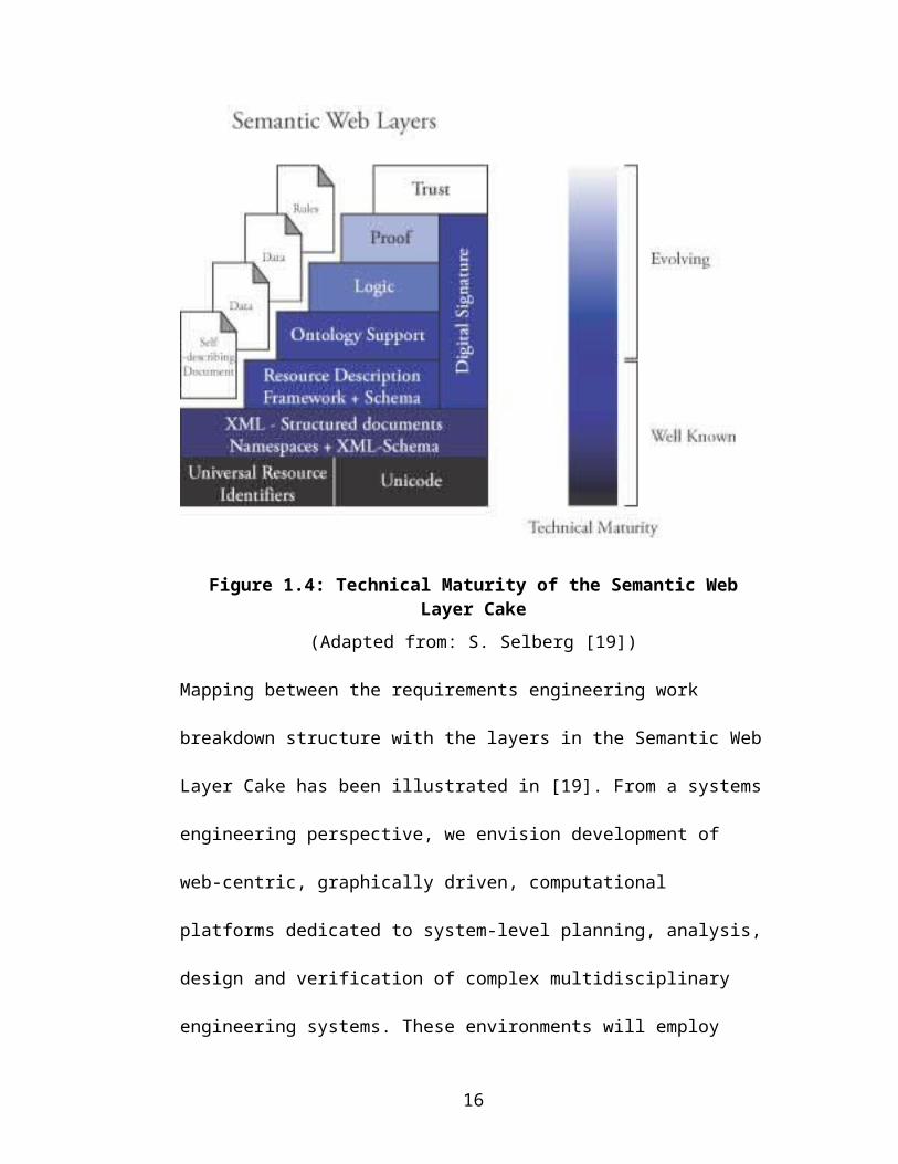
Today’s web is designed for presentation of content to humans – humans are
expected to interpret and understand the meaning of the content. The Semantic
Web is an extension of the current web [15], [16]. It aims to give information well
defined meaning, thereby creating a pathway for machine-to-machine
communication and automated services based on descriptions of semantics. The
web layer cake that realizes this vision is shown in Figure 1.4. With the support of
ontologies [17], [18] that describe a particular problem domain, software agents
will provide automated services by navigating the sea of DAML/OWL documents
and perform logical reasoning on behalf of a user. While each agent will probably
have a very limited scope, armies of simple agents will use the Semantic Web
infrastructure to communicate and collectively achieve more complex tasks (c.f.,
armies of ants).
10

Figure 1.4: Technical Maturity of the Semantic Web Layer Cake
(Adapted from: S. Selberg [19])
Mapping between the requirements engineering work breakdown structure with
the layers in the Semantic Web Layer Cake has been illustrated in [19]. From a
systems engineering perspective, we envision development of web-centric,
graphically driven, computational platforms dedicated to system-level planning,
analysis, design and verification of complex multidisciplinary engineering
systems. These environments will employ semantics descriptions of application
domains, and use ontology to enable communication (or mappings) among
multiple disciplines (e.g., to the engineering team members, to marketing, to
management, and to customers). By delegating formal and precise and repetitive
activities to computers, engineers will be provided with more time to focus on the
creative aspects of engineering systems development.
11

1.6 Organization of Thesis
Figure 1.5: Scope of Work
Figure 1.5 illustrates the scope of this work. Paladin is a software prototype to
support the UML diagrams. The scope of this work involves add different
functions to improve the systems engineering process. Currently the Paladin GUI
supports exporting and importing of various UML diagrams constituting system
structure and behavior and the associated requirements in form of RDF and XML
schema as will be explained in Chapters 2 and 3. Currently, semantics are only
associated with system structure and a simple validation on the basis of these
semantics is attempted. Except for specified XML and RDF scheme to store
12

system behavior diagrams, analysis of associated semantics lie outside the scope of
this work.
Chapter 2 outlines the requirements representation and management and provides
a formal framework to specify the XML / RDF schema and template structure to
store the requirements. With this formal representation, an approach for controlled
visualization of requirements hierarchy-using RDQL is outlined. Various other
features like collapsing of the requirements tree with duplicates and merging of
requirements trees are explained on the basis of the underneath RDF structure of
the requirement document.
Chapter 3 deals with the synthesis of system structure and issues like multiple
viewpoints of the system architecture, merging of two sub-systems etc. An XML
schema to store the visual properties of the object is specified and a RDF model is
developed to store the connectivity information between the objects. This model is
further used to split and merge the system viewpoints.
Chapter 4 deals with bottom-up synthesis of system development from the
reusable components specifications. Object specifications are translated into an
XML schema, which is used to validate the requirements mapped to that particular
component.
13

Chapter 5 provides a working example of design of a home theater system to
illustrate all the concepts and features outlined in Chapters 2, 3 & 4.
A Port – Jack ontology is developed in Chapter 6 to introduce the concept of
reasoning and ontology within system development. Class relationships and the
domain restrictions between the Port and Jack specify what kind of connections is
permitted. This fact base is translated to Jess input and rules are added on the basis
of the instances created in Paladin GUI to ask questions about the validity of
system architecture.
Finally conclusions of the current work and future directions are provided in
Chapter 7.
14

2 Requirement Representation and Management
The basic building block of object-oriented system development is assessment of
customer needs in the form of goals and scenarios, followed by their conversion
into high-level requirements (see Figure 2.6). Requirements define what the
stakeholders – owners, users, and customers – expect from a new system.
Satisfying the needs of all stakeholders may be far from trivial – their demands on
the system may be many, and in some cases, conflicting in nature. So in order to
achieve a proper system design it becomes absolutely essential to have a formal
structural framework in place to manage and enforce project requirements that are
consistent and unambiguous.
Figure 2.6: V-Model of System Development
(Adapted from Hull et al. [20])
15

2.1 Organization of Requirements
Requirements are arranged to support separation of concerns and top-down
decomposition and development of systems. This structure of the requirement
document translates into requirements arranged in hierarchies with the stakeholder
requirements dictating the needs of the overall system (e.g., functional
requirements, interface requirements). Often these requirements are termed as the
Level 0 requirements or the mission statements of the system.
A common practice is to import requirements into systems engineering tools by
parsing a textual document, such as a Microsoft Word [21] document. Many
system engineers find this conversion pathway from Word to a systems
engineering tool convenient. The key limitation of this approach is that
requirements lack semantics and therefore they are largely abstract in nature and
may not be quantifiable. It is the job of the systems engineer to break down these
higher-level requirements into lower-level requirements suitable for quantitative
evaluation.
2.2 Requirements Allocation and Flow Down
Requirement allocation involves the breaking of single attribute value into parts
and assigning values to subordinate values. For example,the overall system budget
is a constrained resource that is divided and allocated to components making up
the system structure. Thus requirements allocation (or flow down) is the process of
16

allocating a set of unique requirements to one or more subsystems or components
(Figure 2.7).
Higher-level requirements are made more granular by refining them and breaking
them down at various levels. The goal of this process is to keep on defining the
complying requirements till we reach a state wherein a particular requirement
could be assigned to a single component. Typically different teams / persons are
responsible for various layers of requirements. So once all the requirements
mapped to a particular component are identified, a team can be assigned to design
that particular component.
Figure 2.7: Flow down of Requirements in the V-Model of System Development
(Adapted from Hull et al. [20])
2.3 Graph Representation of Requirements
Present-day systems engineering tools such as SLATE represent the complying
and defining requirements in a tree structure with respect to the requirement of
17

interest. This model works well if requirements comply / define from a single
source. In the real world problems as the requirements are classified and broken
down in more granular components, they trace across the same level. This happens
because requirements are tightly interdependent with each other across the same
level of abstraction.
This leads to the fact that within the same level one requirement may comply or
define the other requirements. A partial requirement document with requirements
arranged in layers is shown in Figure 2.8. Here requirement C in layer 2 defines
requirement E in layer 3. Conversely, requirement E complies with requirement C.
Figure 2.8: Many-to-Many Relationships in Layers of Requirements
A complying relationship from the top-level requirement in SLATE yields a tree
structure similar to Figure 2.9. As seen there are repetitions of the node GPM
18

Microwave Imager under the Sampling Requirement. This happens because of the
inherent concept of representing the requirement documents as trees. Extracting
requirements from a Word document, which are arranged in paragraphs in the
form of a hierarchy, can be a rationale behind this. But once the requirement
document is extracted, links are modified as the requirements evolve. This renders
the underlying structure of the requirement document as a graph instead of a tree.
This tree representation of the requirement leads to the duplication of the leaf
nodes in a partial view of the requirement document.
Figure 2.9: Tree Representation of Requirements in SLATE
(Source: David F. Everett, NASA Goddard)
19
2.4 Requirement Template Structure
As pointed out by Hull et al. [20], in writing a requirements document, two aspects
have to be carefully balanced:
1. The need to make the requirements document readable.
2. The need to make the set of requirements processable.
While requirements written in a text editor can be readable and facilitates pathway
to import into a systems-engineering tool, a fundamental limitation is the lack of
semantics associated with each requirement. In an effort to mitigate these
limitations, the concept of boilerplates has been proposed by Hull et al. in [20].
Boilerplates define placeholders or tag that can be filled in by the user to make
consistent requirement statements. Boilerplates enable classification and reuse of
requirements across several projects.
In this work, the concept of boilerplates is interpreted as templates. Templates
provide users placeholders, so that they can provide input to those placeholders.
By gathering the values from the placeholders consistent requirement statements
can be generated automatically. Templates are provided for the requirements
relevant in the context of the system structure diagram as a first step. In the system
structure perspective, almost all the requirements can be written in a primitive
format i.e. <attribute, relation, and value>. For example a weight requirement on a
particular component may state that the mass of the component shall not exceed 10
lbs. This in essence translates to <Mass <= 10>
20

Template Definitions
There is one another clear advantage of using the templates in the system structure
context. As we will soon see, we can use this information to support the bottom-up
system development. The following templates have been specified with respect to
the system structure:
1. The <specification> of <object> shall not exceed <value> <units>
2. The <specification> of <object> shall be less than <value> <units>
3. The <specification> of <object> shall be at least <value> <units>
4. The <specification> of <object> shall be greater than <value> <units>
5. The <specification> of <object> shall lie within <lesser value> and
<higher value> units
6. The <specification> of <object> shall be <value (numeric)> <units>
7. The <specification> of <object> shall be <value (alphanumeric)>
<units>
8. The <originating port> of <object> shall connect to <destination port> at
the other end.
Since it is not possible to represent the entire requirements document (For example
behavior requirements, or the higher-level requirements that are abstract and often
non-quantifiable) on the basis of the above templates, template 0 is reserved to
represent these requirements. Requirements at the lowest level in the hierarchy
(leaf requirements) are mapped to individual components in the system structure.
These requirements are in turn grouped on the basis of the components to which
they are mapped and assigned to either teams or to sub-contractors for the final
21

design of the component. Most of these requirements are checked against the
existing component specifications (possibly among a pool of available choices for
that component to promote reuse), before the designer comes up with a final
component that matches the requirements mapped to it. It is especially important
to specify these component-level requirements in the form of templates described
above to promote reuse and the bottom-up synthesis of the system. Templates add
semantics to the individual requirements and in turn can be processed to check the
specifications of the components against them. This results in saving considerable
amount of time and increase in productivity. This practice of checking
requirements against component specification is still manual and as the system
grows more complex, it quickly adds up the number of checks to be performed. A
complete working example with graphical user interface to show the complete
working of templates and specifying inputs will be illustrated in Chapter 4.
2.5 XML Representation of Requirements
Depending upon various project needs, requirements have different attributes
associated with them. For example some of the attributes might be verification
method, description of requirement, creator, priority and rationale etc. These
attributes are customizable depending on the particular vision of documenting a set
of requirements. The extensible markup language (XML) [22] can be used to store
the attributes and their values. Then either a XSLT [23] transform can be used to
transform the XML format of the requirement to generate the requirement
documentation or a Java [24] parser such as Xerces [25] could be written to extract
the value of the attributes and display them in the graphical user interface.
22

Internal Representation of System Requirements
In this software prototype implementation, systems requirement document is
stored as three separate files (see Figure 2.10).
1. Visual properties of the requirements that include the way they are drawn
on the Paladin GUI screen are stored in an XML document. Detail of the
associated XML schema is similar to the XML representation of the system
structure and discussed in detail in Section 3.2.
2. Properties of the individual requirements are encoded in another XML
schema as discussed next.
3. The connectivity information among various requirement objects is stored
in a RDF file, discussed in Section 2.7.
Figure 2.10: Internal Representation of Requirements
XML Tag Set for Representation of Requirements
To start with we consider following attributes of a particular requirement:
23
1. Unique identifier
2. A descriptive name of the requirement
3. Rationale
4. Verification Strategy
5. Comment
6. Creation / Last modified date
7. Description of the Requirement (Text), and
8. Template on which the requirement is based (As defined in the section 2.4)
Example 1: Based on the above information, a sample requirement encoding in
XML might be as follows:
- <Requirement ID="REQ.2.2"> <Name Value="Wall mountability" /> <Rationale Value="Space saving need" /> <Verification Value="Experimental" /> <Comment Value="Detailed agreement between the
cutomer and builder" /> <REVISION Value="Mon Jun 16 14:00:55 EDT 2003" /> <MAPPED_TO Value="TV" /> <Template NO="0" /> <Description Value="The display should be able to be
mounted on the wall" /> </Requirement>
As can be seen above, this XML encoding is based on the generic template 0,
because the requirement is an abstract higher-level requirement.
Example 2: Another requirement example based on second template looks like as
follows:
- <Requirement ID="REQ.3.2"> <Name Value="Cost of TV" /> <Rationale Value="Splitting of overall Cost of the
System" /> <Verification Value="Analytical" /> <Comment Value="Component Level Requirement" /> <REVISION Value="Mon Jun 16 14:00:55 EDT 2003" />
24

<MAPPED_TO Value="TV" /> <Template NO="2" OBJECT="TV" SPECIFICATION="Cost"
SPECLINK="tv1.xml" VALUE1="5000" UNITS="USD" /> <Description Value="Cost of the TV shall be less than
5000 USD" /> </Requirement>
2.6 Requirement Traceability and Controlled Visualization
“In the requirement engineering context, traceability is about understanding how
high-level requirements – objectives, goals, aims, aspirations, expectations, needs
– are transformed into low-level requirements. It is therefore primarily concerned
with the relationships between layers of information [20].”
Requirement traceability is the process of defining and identifying relationships
between two requirements connected to each other at a higher and lower level
respectively. This relationship is termed as the complying and defining
relationship between the two requirements. A requirement at the higher level is
termed as the defining requirement for a requirement it points to at the lower level.
The lower level requirement is in turn named as the complying requirement. For
example, in Figure 2.11 REQ.3.5 is the complying requirement of REQ.2.1 that, in
turn becomes the defining requirement. Requirements can comply and define
within same level as explained in the Figure 2.8. Requirement documents are huge
in nature and with hundreds of requirements in place, often crossing across levels;
it becomes very difficult to comprehend the structure of the requirement
document. Some of the current generation system engineering tools like SLATE
address this problem by representing requirements in a tree hierarchy (See Figure
2.9). The large size of the requirements document drives the need for visualizing a
25

part of it. The underlying graph nature of the requirements leads to duplication of
leaf nodes when viewed as trees. Also there is no mechanism by which the end
user can specify the direction from a particular requirement node and the number
of levels of interest.
Selective Visualization
In this work we propose the concept of a selective visualization of either the
requirements document or the system architecture. By means of selective
visualization we will provide users with the option of selecting a particular node in
the requirement document or the system structure, and ask the question if he / she
want to see the complying or defining or both type of requirements emanating
from that particular node (Figure 2.11). Furthermore, an option of specifying the
number of levels is provided to account for the fact that requirement hierarchies
can be very deep and nested. This selective visualization provides a particular local
viewpoint of the document. Users are provided the flexibility to make any
changes, including addition and deletion of links, which could be merged with
overall document to reflect the changes. The implementation approach to selective
visualization is presented in Section 2.7. A working example and a screenshot of
this feature is illustrated in Chapter 5.
2.7 RDQL Approach to Retrieve Nodes and Links
RDQL [26] is a query language designed for RDF in Jena [27] models. A meta-
model specified in RDF consists of nodes (which could be either literals or
26

resources) and directed edges. RDQL provides a way of specifying a graph pattern
that is matched against the graph structure to yield a set of matches.
In this framework we have requirements (nodes in the RDF meta-model) that are
connected by directed edges specifying the relationship of complying and defining
requirements. When following an edge, the originating node of the link specifies a
defining requirement and the terminating node defines a complying requirement.
Figure 2.11: Extraction and Visualization of "Complying" and "Defining" Requirements in a Requirement Neighborhood
The upper half of Figure 2.11 shows a graph of requirements organized into four
layers. Complying and defining relationships are interleaved among the
requirements. We want to see a controlled visualization of the complying and
defining requirements with respect to REQ.2.1. Expected results are shown for the
27

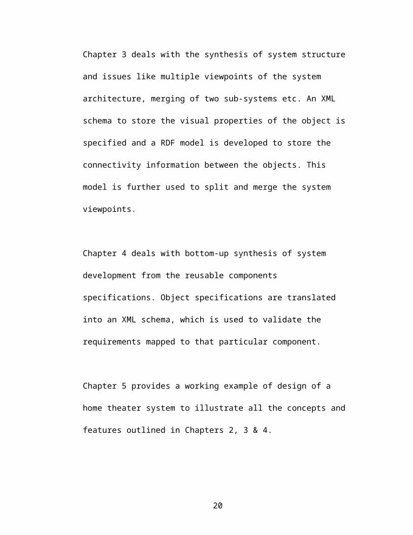
required query at the bottom in Figure 2.11. The equivalent RDF model for the
entire requirement document is illustrated in Figure 2.12.
Figure 2.12: Equivalent RDF Model
RDQL works by executing the string queries, which are passed to a query engine.
The query engine looks at the structure of the query and pattern of the query is
matched against all the triplets in the RDF file on which the query is running. It
returns an iterator of the result set which can be inspected to retrieve the desired
result.
Query for Complying requirements One Level Down
Query string to see the complying requirement is as follows:
String queryString = "SELECT ?X "+
"WHERE(<http://somewhere/"+currentElement+">,
<http://www.w3.org/2001/vcard-rdf/3.0#Given>, ?X)";
28

The Current element is REQ.2.1 from which we want to see the complying
requirements. ?X represents a clause which returns the resources satisfying the
given property.
Query for Defining requirements One Level Up
Query string to see the defining requirement is as follows:
String queryStringLevelUp = "SELECT ?X "+
"WHERE(?X,
<http://www.w3.org/2001/vcard-rdf/3.0#Given>,<http://so
mewhere/"+currentElement+">)";
Query for both Complying and Defining requirements around one level
Query string to see both complying and defining requirements around one level is
obtained by a combination of above two queries executed together.
Multiple level queries can be recursively executed on all the obtained results till it
reaches the number of level or a leaf requirement, whichever occurs earlier. For a
complete working example and screenshots of this utility please refer to Chapter 5.
29

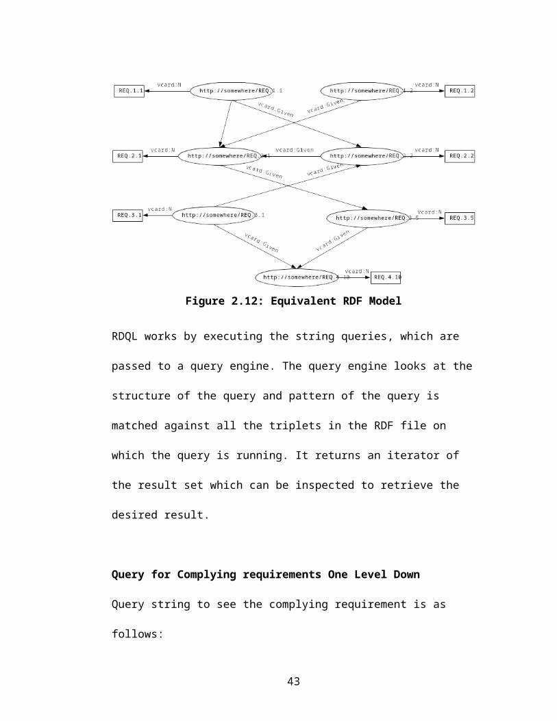
3 Synthesis and Management of System-Level Architectures
As engineering systems become progressively more complex and multi-
disciplinary, so does the need for a formal basis for describing and analyzing the
architectural designs. Hence, our starting point assumes system architectures are
defined by collections of components (having well-defined interfaces and
functionality) and connections (describing the permissible interactions among
components).
A simple example is illustrated in the Figure 3.13, where we have a system
structure composed of two nodes and one edge. For the problem domain of
electronic component assembly, these nodes can be candidate ports and the edge
can be a defining cable, which is trying to connect these two ports. A key
challenge addressed by this work is trying to understand how properties and
functionality associated with the modules and connections can be used to construct
rules that can guide and improve the synthesis of architectural designs. In Figure
3.13 for example, how can we ascertain that the cable is the right kind of cable and
its jacks are compatible with the ports? How do we define rules that can guide
synthesis of the system structure? We will study this problem by investigating a
hierarchy of progressively complicated system models using:
A formal language framework to model simple architectural connections
Architectural connections guided by real time rule checking
30

To identify appropriate “primitives” for collections of system components and
their enabling connectivity, and appropriate rule checking, a case study of a simple
home theater system is illustrated in Chapter 5.
Figure 3.13: System Architectures: Collections of Modules, Connections, and Rules for System Assembly
3.1 Visualization of System Level Architecture
For the design of complex engineering system, an essential requirement for
effective visual communication is the ability to present many kinds of information
in a wide variety of graphical forms. The implementation of appropriate graphical
presentation programs or modules depends heavily on the data handled by the
visualization system and the purpose of the presentation. While the presentation of
numeric, business and scientific data has been studied extensively [28], much less
work has been completed on appropriate models of the visualization of large and
complex system architectures. The purpose of this work is to take the initial steps
towards closing that gap.
In this work we view diagrams of system architectures as a language, in the sense
that the architecture elements (e.g., nodes, edges and attachments) are connected
31

and arranged under certain rules. The visualization process will be regarded as a
translation (or visual mappings) from textual languages (i.e. XML/RDF markup)
into two and three-dimensional visual languages composed of graphical objects,
connection relationships, and geometric relationships. Various well-established
strategies and algorithms for graphical layout and presentation can then be used to
generate diagrams of the system architecture. The generation of aesthetically
pleasing diagrams from the XML/RDF markup currently lies outside the scope of
this work though.
3.2 Storing Visual Properties of System Objects (XML)
Every system object drawn in the graphical user interface has visual properties like
dimension, color, associated hyperlinks, ID and so forth. An XML schema, such as
the one outlined below, is proposed to store the properties of the system objects.
<?xml version="1.0" encoding="UTF-8" ?> - <Project>
- <Graph start="true">- <Object ID="4337267591854790877" shape="PORT_PANEL"
type="47"> <Dimension>44 24 162 129</Dimension>
</Object>- <Object ID="7733796259543882762" shape="CABLE"
type="46"> <Dimension>156 70 374 70</Dimension> <Link fromID="5897562330078363886" toID="-
930171862495999138" /> </Object></Graph>
</Project>
32

Every object has a unique ID reference, a type, such as CABLE or
PORT_PANEL, and a graphical dimension. For the objects such as a cable of type
edge, a LINK reference stores the ID’s of the connecting system objects. This
information is stored in a file database to facilitate the importing and exporting of
the system structure diagrams for later use. A Java parser constructs a DOM
(Document Object Model) [29] tree in the memory, and exports and imports the
XML document into the file system. We anticipate that over time objects will be
added to the GUI. The XML file database will increase in size to accommodate the
expanded capability.
3.3 RDF Approach to Store Objects Connectivity
The Resource Description Framework (RDF) defines a standard for specifying
relationships between objects and classes in a general and simple way. An RDF
statement contains triplets’ viz. subject, predicate and object. Within the semantic
web layer cake, the RDF layer lies above the XML layer. It provides semantics to
the encoded metadata and resolves the circular references, which is an inherent
problem of the hierarchical structure of XML.
In the graphical user interface, it is easy to store the visual properties of the objects
drawn on the screen in a XML file as outlined in Section 3.2. This works fine in
the circumstance where we wish to only parse the XML file and retrieve
information from it either sequentially (using a SAX parser [30]) or randomly
(using a DOM Parser). But it does not provide a very clear picture of the objects
and their connectivity with other objects in the system structure. Generally
33

speaking, a UML diagram drawn in the user interface consists of nodes and edges.
Not only can RDF represent these topological relationships in a natural way, but
also APIs for parsing RDF documents provide powerful graph manipulation
techniques such as intersection and union operations. An implementation approach
to merge two different discipline specific viewpoints is mentioned in Section 3.5.
The need for RDF and XML models
One would like to ask a natural question here? Why would you like to have two
models (RDF&XML) for storing the same type of information? While RDF is a
powerful tool for manipulating the metadata it has its own problems. We are
primarily using the RDF representation to manipulate the diagrams, as per the
user’s requirement. RDF facilitates union, intersection and other graph operations
in an easy manner. XML API’s provides no such capability. But RDF has the
problem of poorly defined semantics, and so we must use the XML APIs to have a
document with meaningful and customizable tags that can be used to extract
information.
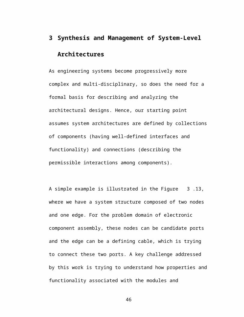
Example RDF Schema to Store a Node and an Edge
Refer to Figure 3.13 for a schematic UML document consisting of two nodes and
one edge. A simple RDF schema to store the connectivity properties are specified
as below:
<rdf:RDF xmlns:rdf='http://www.w3.org/1999/02/22-rdf-syntax-ns#' xmlns:vcard='http://www.w3.org/2001/vcard-rdf/3.0#' >
34

<rdf:Description rdf:about='http://somewhere/A'> <vcard:N>A</vcard:N> <vcard:Given rdf:resource='http://somewhere/B'/> </rdf:Description>
<rdf:Description rdf:about='http://somewhere/B'> <vcard:N>B</vcard:N> </rdf:Description></rdf:RDF>
The first block of code defines XML namespaces that are utilized by the RDF
statements (namespaces take care of name conflicts and enable shorthand notations
for URIs). The xmlns:rdf namespace is the default RDF schema recommended by
W3C. The xmlns:vcard is a simple RDF schema for properties about a person.
This comes prepackaged with the vocabulary of the RDF API. For simple RDF
models vcard schema can be utilized but as the model gets more complex, one
needs to write his or her own schema and associated RDF API. Next two blocks
contain statements about two objects A and B in the system structure. Their labels
are stored through vcard:N property, and the connection between the A and B is
stored by vcard:Given property. Again these two choices are made among a list of
available properties in the vcard schema, which closely resembles the purpose for
which it is used. Above schema of specifying the RDF structure contains following
three triplets obtained from [31] in (subject, predicate, object) format:
1. (http://somewhere/A http://www.w3.org/vcard-rdf/3.0#N “A”)
2. (http://somewhere/A http://www.w3.org/vcard-rdf/3.0#Given
http://somewhere/B)
3. (http://somewhere/B http://www.w3.org/vcard-rdf/3.0#N “B”)
35

The equivalent RDF graph representation is shown in Figure 3.14.
Figure 3.14: RDF Graph of the Data Model
3.4 System Views and Sub-System Diagrams
Today, development of a complex system entails interaction among multiple
disciplines. In the NASA GPM project (the motivating case study application for
this project), system development involves interaction among mechanical, thermal,
aerospace, electrical, computer and communication engineers etc. With such
diversity in the systems development, UML diagrams drawn for the system
structure and behavior quickly grow in size and complexity, and it becomes almost
impossible to comprehend the system in its entirety. Currently, there are two
approaches to addressing this problem:
1. Everybody works on the same big centralized file of the system
architecture with restricted and classified access assigned to each person
interacting with the systems engineering tool. A configuration management
36

tool working in the background keeps track of the changes made, and
provides users with the feedback about the traces of the changes made in
the system diagrams.
2. Engineers come with their own sub-system views, which need to be
merged together in order to form a complete working system.
Both approaches have their strengths and weaknesses. The problem with the first
approach is there is a scope of inconsistency, because a person specifying a
particular design of the architecture will provide data based on the status of the
system at that time. Any changes done to the assumption may remain undiscovered
till a later point of time. Such inconsistencies detected later in the system life cycle
development are proved to be very expensive, and difficult to correct [32].
The second approach avoids the inconsistency problem associated with the first
approach. This occurs because responsibility of systems engineer to integrate the
system from different sources will ensure that every engineer is working from a
consistent set of assumptions. In a paradigm of team-based system development,
each person is working towards the system goals and objectives and is aware of a
set of interfaces and facilities it is exposed to. A system engineer validates such
assumptions at the time of integration. The problem to identify here is the criteria
of integration? Moving from a sub-system view to complete system by merging
these views and then breaking the entire system again into sub-system views
37

requires an iterative process. Present-day systems engineering tools lack such
functionality.
In practice, the solution to promote development by teams in various areas of
expertise lies in merging the two approaches. User specified the disciplines for
each architectural element in the UML diagram that can be stored as XML tags in
the visual properties of the objects. These tags can then be used to split the entire
system diagram into discipline specific system diagrams. The RDQL approach
specified for extracting the part of requirement tree outlined in Section 2.7 can
then be used to selectively visualize and separate a discipline specific view. A
preliminary approach for merging discipline specific modules is discussed next.
3.5 Merging of Discipline Specific System Views
The merging of system diagrams from different domains is associated with
different questions and challenges that need to be answered (See Figure 3.15). We
need to answer what types of rules are associated with merging of two different
system architecture diagram obtained from two different sources. How the invalid
parameters or invalid connections are identified? On what matching condition we
should ascertain that two objects in different system architecture are one and the
same thing, and therefore should be represented as one in the entire system view.
A preliminary step is taken to achieve such merging by taking into consideration
two things:
38

Figure 3.15: Integration of Application Specific Viewpoint of Engineering Systems
1. System objects, which have the same label (e.g., identifying name) in two
different system views are considered as the same system objects and
therefore merged together. An RDF approach to merging the two systems
works really well here. The way the RDF formulation is done in this work,
it points to same URI’s corresponding to system objects having the same
label. This in turn ensures that when the two diagrams are merged together,
those two system objects represent the same entity in the overall system
diagram.
39

2. An ontology approach is defined to specify the rules, which will govern the
system synthesis from the individual components. As a starting point, we
define the ontology containing the ports and jacks and the relationships and
rules of synthesis between them. These rules then guide the system
synthesis. For details refer to Chapter 6. Since ontology can be extended to
incorporate more facts and rules, this step will guide the assumption
conditions, to tell us under which circumstances two objects can be
considered as one and the same.
40

4 Bottom-up Approach to System Development
Bottom-up design (or synthesis) starts with low-level modules and subsystems and
tries to combine them into higher-level entities. The main advantage of bottom-up
design is its use of systems that have already been designed and tested (e.g.
standard electrical components).
Here are some of the salient points worth noting in this context:
1. Reusable components reduce development costs and shorten the time-to-
market.
2. As high-level requirements are decomposed into lower-level requirements,
and models of system behavior and system structure, designers would like
to “look down” into the “product library” to see what components are
available
3. The key question, which arises here: “How do we describe the reusable
component and its capabilities?”
4.1 Component Specification Library
A classical problem in the bottom-up development of system architecture is to
identify the components from the available components library, which if deployed
will meet the requirements of the system. The number and the type of
specifications attached to a particular component can quickly grow as the
component becomes more complex and encompasses more features (Figure 4.16).
Earlier component specifications used to be stored in printed media and with the
41

emergence of the web, now are kept online on the supplying vendors’ websites.
Usually these specifications are stored in portable document format , which can be
downloaded from the websites and printed out by the consumer for further manual
processing.
Figure 4.16: Elements of Object (or Component) - Specification Pair
The problem with such an approach is that it does not support the very concept of
reusability of components across different system architectures, which is a key
42

benefit of the bottom-up approach of system development. This happens because
the portable document format in which the component specifications are stored
lack the semantics associated with that particular component. So it’s the job of the
systems engineer or designer of a particular component to ensure that the
component meets all its requirements. Currently they do so by matching the
specification against all the requirements one by one. This can be a Herculean task.
To take a very simple example, consider a component having 20 specifications
attached to it. There are 50 such components from different vendors, which you
can use in the systems architecture. There are 20 leaf requirements mapped
directly to this component, which it must satisfy. So in the extreme case scenario a
person must check 20,000 cases to see which components could be reused. In real
life case often to avoid this problem, engineers recourse to an easy way out.
Instead of choosing from 50 components they choose from only 5 components.
Unfortunately, this leads to a very narrow design, and may lead to the final system
design, which is not optimized with respect to the component specifications.
The example illustrated above is a very simple scenario. Practically, it is of interest
to know what all requirements are constraining and the design margins associated
with the choice of each particular component. What happens if you relax or
constrain a particular leaf requirement on a component? Which components do
pass / fail the checks? These issues quickly increase the number of checks to be
performed with respect to a single component.
43

4.2 Schema to Store the Component Specification
A big question naturally arises with the above discussion. If a portable document
format for storing the component specification does not associate any semantics to
it, then what form is appropriate? With the advent of the Semantic Web, one of the
possible answers lies in the designing a XML schema specification for the each of
the components by their vendors (Figure 4.17). We would like to create an
interactive design environment where the specifications for components are found
on the web.
Figure 4.17: Synthesis of System Architectures Supported by Product Descriptions on Web
In this work we propose a very simple XML schema for storing each of the
individual component attributes such as one given below:
<Size Value=”32” Units=”inches” />
A more detailed discussion and a more complete example will be illustrated in the
Home Theater development chapter. The above illustration simply specifies that
44

the size of a particular component is 32 inches. This information can be extracted
easily using a Java-XML parser and can be used to make useful inferences out of it
as explained next.
4.3 Requirements Validation against the Component
Specification
Requirements validation is all about checking a particular requirement to see if we
are defining the right requirement and whether it is achievable by the means of the
current technology. There are two aspects of the requirement validation:
We have defined the requirement in a consistent format. By consistent
format we mean the requirement is quantifiable and has a logical meaning.
Current systems engineering tools do not support such a methodology. Once the
requirements are defined on the basis of a template we can say with certainty
that the requirements meet the basic criteria of quantification and non-complex
nature.
Once the proper requirement is in place, the next question is whether that
requirement can be achieved by the means of the available processes /
components. This is very easy to explain in the light of the COTS (commercial
off the shelf) components. If you decided a leaf level requirement, which says
that, I want to have a RAM module, which is greater than 2GB. It’s not
achievable. So that requirement is not valid and it needs to be relaxed. Similar
concept can be extended to processes. In an era when micro level precision was
not obtainable in the machining of a component, it is useless to specify a leaf
45

level requirement, which mandates that level of tolerance on a machined
component.
This second aspect of the requirement validation is manual currently. Once we
have the component specification library schema files, and the requirements
schema we can run a program to check the requirements against the available
component specifications to determine whether a requirement is valid or not. If it
is not, then what are the particular reasons for stating such a reason. It will also aid
in the decision making process of building a component versus buying a
component.
46
5 Development of a Home Theater System
5.1 Problem Statement
Our long-term research and development objective is methodologies and tools for
the combined top-down decomposition and bottom-up synthesis and evaluation of
systems that are likely to be deployed in NASA’s Global Precipitation
Measurement (NASA GPM) project. As a first step, we are trying to understand
the issues and develop prototype tools that will complement present-day
commercial system engineering tools by studying the synthesis and evaluation of a
home theater system.
5.2 System Structure
Putting together the components that build up the entire system architecture is not
a small task as explained in the previous chapters. Here we take up the design of a
home-theater system as an example, which essentially outlines the entire approach
of this bottom-up development process, but in a familiar domain, understandable
by a common person.
The system structure of a home theater system is illustrated in Figure 5.18. The
GUI portrays the essential components assembly, complete with Port and Cable
specification. A system object such as a TV is portrayed as a Port Panel consisting
of several Audio and Video ports. Cables connect two ports. At this point user has
the freedom to use any cable to connect a pair of ports.
47

Figure 5.18: System Structure of the Home-Theater System
(Source: GUI developed by Natasha Kositsyna)
The equivalent XML schema to store the visual properties of the objects is
illustrated in Appendix-A.
5.3 System Requirements
Even a simple system such a home theater can have a large number of
requirements. For the purpose of illustration, we specify a small subset here with
requirements arranged in hierarchies. Customer needs lies at the top of the
hierarchy (Level 1). Requirements flow down to next higher-levels and they
become more specific. At the bottom of this hierarchy are the requirements that we
48

can assign to individual components. In practice, when this level is attained, a
design team is made responsible for designing that particular component and
therefore owns the requirements associated with the component.
Level 1 Requirements – Preliminary Agreement between Customer and
Builder
REQ.1.1: I need to assemble a good home theater system from the market.
REQ.1.2: The total cost must be less than or equal to USD 8000.
Level 2 Requirements – Detailed Agreement between customer and Builder
REQ.2.1: The home theater shall have a large display screen.
REQ.2.2: The display should be able to be mounted on the wall.
REQ.2.3: The system shall have a high fidelity audio system.
REQ.2.4: All components will be bought from the market.
REQ.2.5: Components of the systems shall be connected to each other.
As mentioned earlier, requirements at each subsequent level are more refined.
Also, we need to establish the complying and defining requirements relationships
at this stage. As illustrated in Figure 5.19, REQ.1.1 is a defining requirement for
all level two requirements, because all the requirements essentially defines, what is
“good” for the customer (REQ.2.1 thru REQ.2.3 & REQ.2.5) and the fact that user
wants to assemble the system from the components bought from “market”
(REQ.2.4). The cost requirement (REQ.1.2) is a defining requirement for REQ.2.1
thru REQ.2.3 because the user is constrained by the budget and so he cannot buy
49
whatever is the best in the market. As mentioned in section 2.3, requirements can
comply and define at the same level, REQ.2.1 thru REQ.2.3 are complying
requirements of REQ.2.4 because the components need to be bought from the
market. For example, in the era of mono aural audio signals, a high-fidelity system
can’t mean a surround sound system because such systems were unavailable in the
market.
Level 3 Requirements – Component Requirements
REQ.3.1: Size of the TV shall be at least 32 inches.
REQ.3.2: Thickness of the TV shall not be greater than 6 inches.
REQ.3.3: Cost of the TV shall be less than 5000 USD.
REQ.3.4: Cost of the Amplifier shall be less than 600 USD.
REQ.3.5: Output of the speaker shall lie within 200 watts and 350 watts.
REQ.3.6: The AudioOut Port of TV shall connect to AudioIn port of Amplifier.
REQ.3.7: The AudioOut Port of VCR shall connect to AudioIn Port of Amplifier.
REQ.3.8: The AudioOut Port of DVD shall connect to AudioIn Port of Amplifier.
REQ.3.9: The VideoOut Port of VCR shall connect to VideoIn Port of TV.
REQ.3.10: The AudioOut Port of Amplifier shall connect to AudioIn Port of
Speakers.
Relationships between the requirements at this level can be reasoned in a similar
way. For example, REQ.3.6 through REQ.3.10 is the complying interface
requirements of REQ.2.5. It has to be kept in mind that the relationship between
50

two requirements is not unique and it depends on the perspective of the engineer
designing the system. These links and relationships keep on changing as the
system design evolves. The requirements document is illustrated in Figure 5.19.
Figure 5.19: Requirements Document Structure
The RDF representation of the above requirement hierarchy is illustrated in
Appendix-B.
5.4 Requirement Template Structure
As discussed in Section 2.4 quantifiable component-level requirements can be
represented using templates to provide a formal structure to the requirement input.
Figure 5.20 illustrates the process of attaining REQ.3.1 input, which says Size of
TV shall be at least 32 inches. Other attributes of the requirements like Name,
Rationale, Description and Revision are also illustrated. The user input is
translated to a requirement XML property file illustrated in Appendix-C.
51

Figure 5.20: Requirement Template Input Dialog
5.5 Requirements Traceability and Controlled Visualization
As we can see the requirements hierarchy shown in Figure 5.19 reflect a complex
requirement structure, with requirements linking each other within and across
levels. Requirement traceability is illustrated in Figure 5.21, Figure 5.22 and
Figure 5.23. It provides screenshots of complying, defining and both type of
relationships based on the user input of root element (REQ.2.3) and number of
levels (1) in the traceability options dialog (shown along).
52

Figure 5.21: Complying Requirements (1-Level) w.r.to REQ.2.3
Figure 5.22: Defining Requirements (1-Level) w.r.to REQ.2.3
53

Figure 5.23: Complying and Defining Requirements (1-Level) w.r.to REQ.2.3
5.6 Merging Two Requirement Trees
Requirement trees or system structure diagrams consist of nodes and edges.
Consideration of mobile and geographically separated integrated product teams
may lead to separate development of parts of the system. These discipline specific
viewpoints need to be stitched together to see the complete system architecture and
requirements graph. Figure 5.24 represents two requirement hierarchies obtained
from two different sources. These need to be merged together on the basis of the
common objects (as a first step, the merging criterion is the label identifying
common objects) via a merge operation to yield Figure 5.25.
54

Figure 5.24: Two Different Requirement Hierarchies Prior to Merging Operation
Figure 5.25: Requirements Graph after the Merging Operation
55

5.7 Collapsing Requirement Tree with Duplications
Section 2.3 specifies the underlying graph structure of requirements, which when
represented as tree yields duplicate nodes Figure 2.9. Since in this work, a RDF
approach is followed to specify the relationships between the nodes and edges, a
collapse operation can be performed on trees with duplicate nodes to bring out the
underlying graph structure. This functionality is especially useful in bigger project
contexts (such as NASA-GPM) having hundreds of requirements. Figure 5.26 and
Figure 5.27 represent the requirements structure before and after the collapsing
operations respectively.
Figure 5.26: Requirements Tree Prior to Collapsing Operation
56

Figure 5.27: Requirements Graph After Collapsing Operation
5.8 Components Library
The specifications of the components are stored in an XML database comprised of
individual components and their associated specifications lists. Component level
requirements (Level 3 in this case) are checked against the specifications to
validate the usability of a particular component to be used in the system structure.
In the present example a very simple schema for storing the specification of a
particular TV is shown as below:
<?xml version="1.0" encoding="UTF-8" ?> <!-- Specification of the TV --> <Object Name="TV"> <Size Value="27" Unit="inches" /> <Brand Value="Sony" />
57
<Cost Value="1400" Units="USD" /> <Type Value="Plasma" /> <Mass Value="50" Unit="lbs" /> <Thickness Value=”5” Unit=”inches” /> </Object>
This is by no means the complete specification. This serves to illustrate the schema
and includes a few specifications. As outlined in the Chapter 4 this schema file
will be stored on vendor web sites and will be downloaded on the fly. Better still
there could be domain ontology with the relevant properties which could be
utilized by a reasoning engine such as Jess to come up with a quick answer to the
requirement validation query.
5.9 Low-Level Validation of Requirements
When we see the above specification file and compare this particular instance of a
TV with the requirements we specified, we see that this TV clears the
requirements on the cost and thickness, but fails on the screen size. In the toolkit
when we invoke the command to check the requirements against the specification
file we get a dialog box (see Figure 5.28), signaling user to take corrective action.
Figure 5.28: Error Dialog thrown during Leaf Requirement Validation against Object Specification
58

6 Architecture Validation using Facts and Rules
The use of ontology provides a very powerful way to describe objects and their
relationships to other objects. Ontology is “a set of knowledge terms, including the
vocabulary, the semantic interconnections, and some simple rules of inference and
logic for some particular topic [17], [18].”
While the exact picture of ontology is unclear, the problems ontology needs to
overcome are agreed upon. They are to facilitate communication among people,
among machines, and between humans and machines. To do this, ontology needs
to describe a formal conceptualization within a particular domain, which does
three things:
1. Provides a semantic representation of each entity and its relationships to
other entities;
2. Provides constraints and rules that permit reasoning within the ontology;
3. Describes behavior associated with stated or inferred facts.
6.1 Schematic Model Checking Procedure
59

In this work, we propose to develop a Port Jack Ontology to describe the
relationships between the port and jack connectivity in the system architecture.
This ontology describes the constraining relationship between the ports and jacks
and specifies what type of connections is allowed in the form of domain
restrictions. We start with an Ontology having only an audio cable and the
associated ports. The pathway of this ontology development and validation of
system architecture is illustrated in Figure 6.29.
Figure 6.29: Overall Schema for Ontology-Enabled Model Checking
60

In the above schematic, there are two parallel paths namely Ontology development
and its integration with the Paladin GUI to achieve model checking. Classes and
the constraining relationships in the form of domain restrictions are defined on the
right hand side. This Ontology in turn is used to validate the system architecture
developed in the Paladin GUI and the steps are shown on the left hand side of the
diagram. The Paladin GUI generates the instances of classes defined in the
ontology along with the connectivity between the ports and the jacks in form of
constraints as specified by the user. The constraints defined by the user and the
constraints defined in the ontology need to be true simultaneously to conclude that
system architecture is consistent with ontology definitions.
In the real world, the right hand side of the above schematic will come from the
manufacturers who will define the ontologies for their product lines and store them
on their respective web sites. These ontologies will be imported at the time of
system architecture validation into the GUI dynamically and will determine if it is
consistent with the manufacturer intentions of using that particular component. All
the above steps in the schematic are discussed in detail next.
6.2 Class Relationships in Port Jack Ontology
DAML+OIL (Darpa Agent Markup Language) [14] and the OWL (Web Ontology
Language) [33] are two different syntaxes with which one can create ontology.
DAML+OIL is built on the top of RDF but provides much richer semantics and
schema. For the purpose of illustration we will take a simple example here. In this
example we have only one cable and associated ports and their definitions stored
61

in the ontology. This cable is a typical Audio cable containing two jacks namely
Audio Out jack and Audio In jack. The corresponding ports are the Audio Out
Ports and the Audio In Ports. The definition of the cable includes what type of port
and jack connections are allowed and what type of jacks a cable can have at its two
ends. Figure 6.30 illustrates the class definitions and the relations between the
instances as defined in the Ontology.
Figure 6.30: Class Relationship in the Port-Jack Ontology
The converts_to relationship signifies the fact that an audio cable has two different
types of audio ports at two ends. Enforcing the rule in a logic engine, which will
validate the connection of the cable as explained later, can enforce this. The point
to note here is that Ontologies are not unique in the sense that it depends largely on
the creator’s perspective. Various classes and the relationships can be defined in
many ways. For example one might think to make a certain thing attribute of the
class instead of making it a different class. Another person might think in a
different way.
6.3 Equivalent DAML Representation of the Ontology
Once the class and the various relationships are thought upon we need to create an
equivalent DAML representation of the same. There are two ways to achieve this:
62

The DAML representation can be hard coded in a text file by writing the
classes and their relationships manually.
With the evolution of ontology there are many graphical user interfaces
that have evolved to avoid the approach outlined in the first method. These
graphical user interfaces take in the classes and their relationships and then
generate the DAML or other representation as needed.
Figure 6.31: A Screenshot of Protégé GUI Illustrating Class Properties of AudioInJack
We will take this second approach as the first approach is not very intuitive and
often results into the definition of the ontology, which is not consistent. The tool
we have used for defining the Ontology is Protégé [34] developed in Stanford
University with a plugin to generate the DAML file from SRI [35]. Figure 6.31
63

and Figure 6.32 provide snap shots of the tool in action to define the class
AudioOutJack and the slot converts_to. A slot in Protégé maps to domain
restriction in DAML. For a description and examples on domain restriction, slots
and the subclass relationship the reader is referred to [36].
Figure 6.32: A Screenshot of Protege GUI Illustrating Slot Properties of converts_to
The Ontology created using this software can be exported in the HTML format,
which can be browsed (Figure 6.33) in a web browser such as Netscape [37]. It
facilitates the documenting of the Ontology, as the class relationships and the
properties associated with each are stored in the HTML format suitable for
browsing.
64
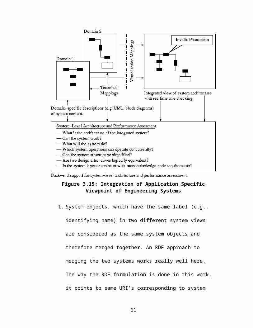
The DAML plugin used along with Protégé generates the DAML file (Appendix-
D) corresponding to this Ontology. A small snippet of the DAML generated is as
follows:
<daml_oil:Class rdf:ID="AudioOutJack"> <rdfs:subClassOf> <daml_oil:Restriction> <daml_oil:toClass rdf:resource="#AudioInJack"/> <daml_oil:onProperty rdf:resource="#converts_to"/> </daml_oil:Restriction> </rdfs:subClassOf> <rdfs:subClassOf rdf:resource="#Jack"/></daml_oil:Class>
Figure 6.33: Screenshot of the Exported Ontology Documentation in HTML
An equivalent graphical representation as obtained from the W3C RDF Validation
service [31] is illustrated in Figure 6.34.
65

Line 1 specifies that AudioOutJack belongs to class schema of daml_oil. Line 2-7
specifies that the coverts_to property of an instance of AudioOutJack should have
an instance of AudioInJack as a value. Line 8 enforces the subclass relationship
between the AudioOutJack and the Jack. It means that an instance of
AudioOutJack is also an instance of a Jack
Figure 6.34: Equivalent RDF Graph of the Port-Jack Ontology
6.4 Conversion of DAML Representation to Jess Facts
The instances of the classes defined in the Ontology are created in our graphical
user interface. We can use the above Ontology to check the validity of a particular
cable and port connection defined by the user in the structure diagram of the
system. To do this we need to use a rule engine such as Jess [38] to convert the
66
Ontology definitions and relations into a series of assertions or known facts. This
is achieved by using the DAMLJessKB [39] converter developed at Drexel
University [40]. It defines a set of Java API’s and packages, which takes the
DAML representation of the ontology as input. It streams the underlying DAML
model into a series of triples and converts it to Jess assertions. A particular
assertion in Jess language looks like:
assert ((PropertyValue http://www.w3.org/1999/02/22-rdf-syntax-ns#typehttp://www.isr.umd.edu/~vmayank/SimpleOntology.daml#Porthttp://www.daml.org/2001/03/daml+oil#Class))
6.5 Addition of Rules and Execution of Rete Algorithm
Rules are then generated using the Java API of DAMLJessKB to enforce the
ontology relationships. An example rule to enforce a jack and a port connection
looks like:
(defrule allowed-jacka-porta-config(PropertyValuehttp://www.w3.org/1999/02/22-rdf-syntax-ns#type?anonhttp://www.daml.org/2001/03/daml+oil#Restriction)
(PropertyValuehttp://www.daml.org/2001/03/daml+oil#toClass?anonfile:/D:/forte/j2sdk1.4.1/jre/lib/ext/SimpleOntology.daml#JackA)
(PropertyValuehttp://www.daml.org/2001/03/daml+oil#onProperty?anonfile:/D:/forte/j2sdk1.4.1/jre/lib/ext/SimpleOntology.daml#connects_to)
(PropertyValuehttp://www.w3.org/2000/01/rdf-schema#subClassOffile:/D:/forte/j2sdk1.4.1/jre/lib/ext/SimpleOntology.daml#PortA?anon)=>(printout t "Jack A consistent with Port A as per ontology definition" crlf)) ; end defrule construct
67
Jack A and port A instances are generated programmatically from the GUI as per
the user input and fed into this defrule construct of Jess. For a complete listing of
the Jess facts and the generated rules refers to Appendix-E.
This DAMLJessKB API invokes the core Rete [41] algorithm of Jess to evoke the
set of rules against the known facts and checks the specified instances. After
execution it determines whether the Jacks and Ports are connected properly as per
the Ontology definitions or not. It illustrates reasons for the non-conforming
architecture.
68

7 Conclusions and Future Work
7.1 Conclusions
Large and complex multi-disciplinary systems development approach is moving
towards bottom-up development paradigm. With vendors specializing in particular
products, this approach emphasizes reuse of components and outsourcing
wherever possible. The need to address and facilitate such development has been
attempted in this work. We see overall system development as a confluence of top-
down and bottom-up approach. An analysis of present-day techniques to develop
systems starting from abstract concepts and refining them (top-down) has been
presented. In this process we identified the problem faced by the current systems
engineers and provide a solution to some of them in the form of a software
prototype Paladin.
With the evolution of semantic web technologies, computing paradigm is shifting
towards utilization of web-based contents with associated semantics. A primitive
step is taken to analyze the ontology based computing and its relation to validate
the systems architecture. RDF and XML based computing infrastructure have been
employed extensively to create and query the database and analyze the
connectivity relationships between the objects. This approach has leveraged the
graph operations and simplified it to answer some of problems associated with
controlled visualization and discipline specific system viewpoints.
69
7.2 Future Work
This work opens up a whole new domain of areas that could be worked upon in
order for the development of a complete Systems Engineering tool to aid the
current practices in the field. Some of the relevant work (but not limited to) in this
context is illustrated next.
1. A key idea in this XML encoding is to make the requirements document
compatible with the AP233 [42], [43], [44] standard of data exchange.
AP233 is under development for providing a method of data interchange
between various tools such as SLATE, DOORS, Rational Requisite PRO,
and CORE [45] etc so that these tools can understand the data represented
in other tools. With the basic infrastructure already in place, the XML
encoding of requirements can be readily converted to make it consistent
with the AP233 format once it is fully developed and adapted by various
vendors. This capability will enhance the ability of the tools to import data
from other tools and represent it in our GUI.
2. As the semantic web drives the storage of the component specification onto
the web, there will be a pressing need for a specification builder GUI,
which will be used to provide the necessary data input and export it into a
standard component specification schema agreed upon the world wide
community of the product vendors.
3. Once the requirements are elicited correctly from the use cases and
scenarios, the next step is to generate the system architecture alternatives
and do the trade-off and optimization. A limited capability of importing
70

various components manually from the components library is already in
place. It will be beneficial to have a framework that will allow the user to
analyze the entire database of components and provide the designer with
the critical feedback on the design margins based on the imported
components specification. A framework for integrating the presented
graphical user interface with optimization tools such as CPLEX needs to
carry out linear and non-linear optimization to generate the tradeoff surface
and inferior solutions.
4. Present work is based solely on the requirements representation, system
structure and mapping between them. Although a framework for building
and exporting the behavior diagram of the system (such as state charts,
functional flow block diagrams), the semantics associated with them is still
missing. This tool could be integrated with simulation tools such as Arena
and finite state automata to carry out simulations and verification of the
system.
5. A simple Jack and Port ontology is presented as part of this work to
analyze the connection between components and check the feasibility of
the system architecture. This ontology can be extended to define the entire
domain of the graphical user interface to make it more intelligent and will
not allow users to make the mistakes.
71

6. Use cases are the building blocks of the system architecture as they provide
subtle hints for the candidate system objects. The process of generating the
system design involves iterative translation from the use cases to scenarios
to requirements to system architecture (see Figure 7.35). These all
processes need to be consistent. There is a need for a tool, which will allow
users to generate the activity diagrams automatically based on the
description of use cases. An initiative along this direction has already been
taken [46].
Figure 7.35: Pathway from Use Cases to Scenarios and High-Level Requirements
7. Last but not the least, the visualization of systems architecture needs to be
polished, as the diagrams should look aesthetically pleasant. An integration
of graph drawing algorithms [47], [48], [49] with possible import of
packages from existing sources [50], [51], [52] could be integrated into the
tool to provide the automatic graph layout as per the specified algorithm.
72

Appendix-A XML Representation of the Home Theater
Structure
This data file represents the schema for storing the visual properties of the objects /
requirements created in the Paladin toolkit. Some of the Visual information, which
is needed to redraw the component on the screen, includes its dimension, type of
the object, its ID and separate graphs in a particular view. These all information is
stored in a hierarchy of corresponding tags inside the object.
<?xml version="1.0" encoding="UTF-8" ?> - <Project>- <Graph start="true">- <Object ID="4337267591854790877"
shape="PORT_PANEL" type="47"> <Dimension>44 24 162 129</Dimension>
</Object>- <Object ID="7733796259543882762" shape="CABLE"
type="46"> <Dimension>156 70 374 70</Dimension> <Link fromID="5897562330078363886" toID="-
930171862495999138" /> </Object>- <Object ID="-4227801706294106407" shape="CABLE"
type="46"> <Dimension>257 211 131 126</Dimension> <Link fromID="-2400144836664991188" toID="-
357089398145097484" /> </Object>- <Object ID="-212117402712482581" shape="CABLE"
type="46"> <Dimension>342 277 462 277</Dimension> <Link fromID="-3941780722503364518" toID="-
349280628884105229" /> </Object>- <Object ID="6823559814550310809" shape="CABLE"
type="46"> <Dimension>213 282 171 349</Dimension> <Link fromID="9127970985135915536"
toID="5040508452007293263" /> </Object>- <Object ID="-5116623924643214452"
shape="PORT_PANEL" type="47"> <Dimension>458 246 556 313</Dimension>
73

</Object>- <Object ID="6425550699874130311" shape="CABLE"
type="46"> <Dimension>419 103 321 212</Dimension> <Link fromID="-8041419687310972460"
toID="8674520345213607480" /> </Object>- <Object ID="9179454190841196613" shape="CABLE"
type="46"> <Dimension>100 126 100 348</Dimension> <Link fromID="7619911316542097551"
toID="1945471842619664061" /> </Object>- <Object ID="-5505813272925557232"
shape="PORT_PANEL" type="47"> <Dimension>212 213 346 327</Dimension>
</Object>- <Object ID="-3941780722503364518" shape="PORT"
type="48"> <Dimension>332 267 352 287</Dimension> <Link toID="-5505813272925557232" />
</Object>- <Object ID="-349280628884105229" shape="PORT"
type="48"> <Dimension>452 267 472 287</Dimension> <Link toID="-5116623924643214452" />
</Object>- <Object ID="5040508452007293263" shape="PORT"
type="48"> <Dimension>161 339 181 359</Dimension> <Link toID="-6056953104219719173" />
</Object>- <Object ID="9127970985135915536" shape="PORT"
type="48"> <Dimension>203 272 223 292</Dimension> <Link toID="-5505813272925557232" />
</Object>- <Object ID="-8631530153037221977" shape="PORT"
type="48"> <Dimension>272 317 292 337</Dimension> <Link toID="-5505813272925557232" />
</Object>- <Object ID="1945471842619664061" shape="PORT"
type="48"> <Dimension>90 338 110 358</Dimension> <Link toID="-6056953104219719173" />
</Object>- <Object ID="-930171862495999138" shape="PORT"
type="48"> <Dimension>364 60 384 80</Dimension> <Link toID="-6397728818364024033" />
</Object>
74

- <Object ID="-8041419687310972460" shape="PORT" type="48">
<Dimension>409 93 429 113</Dimension> <Link toID="-6397728818364024033" />
</Object>- <Object ID="-2400144836664991188" shape="PORT"
type="48"> <Dimension>247 201 267 221</Dimension> <Link toID="-5505813272925557232" />
</Object>- <Object ID="8674520345213607480" shape="PORT"
type="48"> <Dimension>311 202 331 222</Dimension> <Link toID="-5505813272925557232" />
</Object>- <Object ID="-357089398145097484" shape="PORT"
type="48"> <Dimension>121 116 141 136</Dimension> <Link toID="4337267591854790877" />
</Object>- <Object ID="7619911316542097551" shape="PORT"
type="48"> <Text>A</Text> <Dimension>90 116 110 136</Dimension> <Link toID="4337267591854790877" />
</Object>- <Object ID="5897562330078363886" shape="PORT"
type="48"> <Dimension>146 60 166 80</Dimension> <Link toID="4337267591854790877" />
</Object>- <Object ID="5888226028590857221" shape="LABEL"
type="40"> <Text>TV</Text> <Dimension>91 46 111 68</Dimension> <Link toID="4337267591854790877" />
</Object>- <Object ID="-3464995602672494238" shape="LABEL"
type="40"> <Text>Home<nl>Theater<nl>Amp</Text> <Dimension>260 254 308 308</Dimension> <Link toID="-5505813272925557232" />
</Object>- <Object ID="5766306240200143317" shape="LABEL"
type="40"> <Text>DVD</Text> <Dimension>97 364 128 386</Dimension> <Link toID="-6056953104219719173" />
</Object>- <Object ID="-1125144154021993343" shape="LABEL"
type="40"> <Text>Speaker 2</Text> <Dimension>482 268 544 290</Dimension>
75

<Link toID="-5116623924643214452" /> </Object>- <Object ID="-2548812202442281956" shape="LABEL"
type="40"> <Text>Audio Out</Text> <Dimension>352 289 411 311</Dimension> <Link toID="-3941780722503364518" />
</Object>- <Object ID="-8080414068675241044" shape="LABEL"
type="40"> <Text>Audio In</Text> <Dimension>404 242 454 264</Dimension> <Link toID="-349280628884105229" />
</Object>- <Object ID="5307719630104561260" shape="LABEL"
type="40"> <Text>Speaker 1</Text> <Dimension>264 436 326 458</Dimension> <Link toID="-7075534318685230158" />
</Object>- <Object ID="-7072323418332330746" shape="LABEL"
type="40"> <Text>Video In</Text> <Dimension>32 135 82 157</Dimension> <Link toID="7619911316542097551" />
</Object>- <Object ID="1702425072755131235" shape="LABEL"
type="40"> <Text>Audio In</Text> <Dimension>157 247 207 269</Dimension> <Link toID="9127970985135915536" />
</Object>- <Object ID="-8447650783263509459" shape="LABEL"
type="40"> <Text>Audio Out</Text> <Dimension>170 120 229 142</Dimension> <Link toID="-357089398145097484" />
</Object>- <Object ID="-566334250751855220" shape="CABLE"
type="46"> <Dimension>282 327 282 420</Dimension> <Link fromID="-8631530153037221977" toID="-
8831546525121722840" /> </Object>- <Object ID="-8831546525121722840" shape="PORT"
type="48"> <Dimension>272 410 292 430</Dimension> <Link toID="-7075534318685230158" />
</Object>- <Object ID="-6397728818364024033"
shape="PORT_PANEL" type="47"> <Dimension>373 45 522 105</Dimension>
</Object>
76

- <Object ID="-6056953104219719173" shape="PORT_PANEL" type="47">
<Dimension>55 347 205 393</Dimension> </Object>- <Object ID="-3960374134036905440" shape="LABEL"
type="40"> <Text>Audio Out</Text> <Dimension>120 305 179 327</Dimension> <Link toID="5040508452007293263" />
</Object>- <Object ID="4268930084446139984" shape="LABEL"
type="40"> <Text>Video Out</Text> <Dimension>32 305 91 327</Dimension> <Link toID="1945471842619664061" />
</Object>- <Object ID="7722487328336319391" shape="LABEL"
type="40"> <Text>Audio In</Text> <Dimension>239 169 289 191</Dimension> <Link toID="-2400144836664991188" />
</Object>- <Object ID="-4131231084681303988" shape="LABEL"
type="40"> <Text>Video In</Text> <Dimension>173 37 223 59</Dimension> <Link toID="5897562330078363886" />
</Object>- <Object ID="-8708940313658193746" shape="LABEL"
type="40"> <Text>Video Out</Text> <Dimension>305 81 364 103</Dimension> <Link toID="-930171862495999138" />
</Object>- <Object ID="-1380059460790430106" shape="LABEL"
type="40"> <Text>Audio In</Text> <Dimension>350 200 400 222</Dimension> <Link toID="8674520345213607480" />
</Object>- <Object ID="600277411624340355" shape="LABEL"
type="40"> <Text>VCR</Text> <Dimension>445 65 476 87</Dimension> <Link toID="-6397728818364024033" />
</Object>- <Object ID="-5640294704235571447" shape="LABEL"
type="40"> <Text>Audio Out</Text> <Dimension>428 120 487 142</Dimension> <Link toID="-8041419687310972460" />
</Object>
77

- <Object ID="-7075534318685230158" shape="PORT_PANEL" type="47">
<Dimension>251 417 344 476</Dimension> </Object>- <Object ID="2386762432953440281" shape="LABEL"
type="40"> <Text>Audio Out</Text> <Dimension>302 332 361 354</Dimension> <Link toID="-8631530153037221977" />
</Object>- <Object ID="648612592363060694" shape="LABEL"
type="40"> <Text>Audio In</Text> <Dimension>302 386 352 408</Dimension> <Link toID="-8831546525121722840" />
</Object> </Graph>
</Project>
78

Appendix-B RDF Representation of the Requirement
Structure
This data file outlines a schema to store the connectivity information of the
requirement objects created in the Paladin toolkit in the RDF. All requirements
correspond to a resource, which have their ID’s as the Name attribute, and
connectivity to other requirement objects are specified through the VCARD:Given
property.
<rdf:RDF xmlns:rdf='http://www.w3.org/1999/02/22-rdf-syntax-ns#' xmlns:vcard='http://www.w3.org/2001/vcard-rdf/3.0#' >
<rdf:Description rdf:about='http://somewhere/REQ.3.1'> <vcard:N>REQ.3.1</vcard:N> </rdf:Description>
<rdf:Description rdf:about='http://somewhere/REQ.3.5'> <vcard:N>REQ.3.5</vcard:N> </rdf:Description>
<rdf:Description rdf:about='http://somewhere/REQ.3.9'> <vcard:N>REQ.3.9</vcard:N> </rdf:Description>
<rdf:Description rdf:about='http://somewhere/REQ.2.5'> <vcard:N>REQ.2.5</vcard:N> <vcard:Given rdf:resource='http://somewhere/REQ.3.6'/> <vcard:Given rdf:resource='http://somewhere/REQ.3.7'/> <vcard:Given rdf:resource='http://somewhere/REQ.3.8'/> <vcard:Given rdf:resource='http://somewhere/REQ.3.9'/> <vcard:Given rdf:resource='http://somewhere/REQ.3.10'/> </rdf:Description>
<rdf:Description rdf:about='http://somewhere/REQ.3.6'> <vcard:N>REQ.3.6</vcard:N> </rdf:Description>
<rdf:Description rdf:about='http://somewhere/REQ.2.2'> <vcard:N>REQ.2.2</vcard:N> <vcard:Given rdf:resource='http://somewhere/REQ.3.2'/> <vcard:Given rdf:resource='http://somewhere/REQ.3.3'/> </rdf:Description>
<rdf:Description rdf:about='http://somewhere/REQ.3.10'>
79

<vcard:N>REQ.3.10</vcard:N> </rdf:Description>
<rdf:Description rdf:about='http://somewhere/REQ.3.3'> <vcard:N>REQ.3.3</vcard:N> <vcard:Given rdf:resource='http://somewhere/REQ.3.2'/> </rdf:Description>
<rdf:Description rdf:about='http://somewhere/REQ.1.1'> <vcard:N>REQ.1.1</vcard:N> <vcard:Given rdf:resource='http://somewhere/REQ.2.1'/> <vcard:Given rdf:resource='http://somewhere/REQ.2.2'/> <vcard:Given rdf:resource='http://somewhere/REQ.2.5'/> <vcard:Given rdf:resource='http://somewhere/REQ.2.3'/> <vcard:Given rdf:resource='http://somewhere/REQ.2.4'/> </rdf:Description>
<rdf:Description rdf:about='http://somewhere/REQ.2.1'> <vcard:N>REQ.2.1</vcard:N> <vcard:Given rdf:resource='http://somewhere/REQ.3.1'/> <vcard:Given rdf:resource='http://somewhere/REQ.3.2'/> <vcard:Given rdf:resource='http://somewhere/REQ.3.3'/> </rdf:Description>
<rdf:Description rdf:about='http://somewhere/REQ.2.4'> <vcard:N>REQ.2.4</vcard:N> <vcard:Given rdf:resource='http://somewhere/REQ.2.3'/> <vcard:Given rdf:resource='http://somewhere/REQ.2.2'/> <vcard:Given rdf:resource='http://somewhere/REQ.2.1'/> </rdf:Description>
<rdf:Description rdf:about='http://somewhere/REQ.3.7'> <vcard:N>REQ.3.7</vcard:N> </rdf:Description> <rdf:Description rdf:about='http://somewhere/REQ.3.2'> <vcard:N>REQ.3.2</vcard:N> </rdf:Description>
<rdf:Description rdf:about='http://somewhere/REQ.1.2'> <vcard:N>REQ.1.2</vcard:N> <vcard:Given rdf:resource='http://somewhere/REQ.2.1'/> <vcard:Given rdf:resource='http://somewhere/REQ.2.2'/> <vcard:Given rdf:resource='http://somewhere/REQ.2.3'/> <vcard:Given rdf:resource='http://somewhere/REQ.2.4'/> </rdf:Description>
<rdf:Description rdf:about='http://somewhere/REQ.3.4'> <vcard:N>REQ.3.4</vcard:N> <vcard:Given rdf:resource='http://somewhere/REQ.3.5'/> </rdf:Description>
<rdf:Description rdf:about='http://somewhere/REQ.2.3'> <vcard:N>REQ.2.3</vcard:N> <vcard:Given rdf:resource='http://somewhere/REQ.3.4'/> <vcard:Given rdf:resource='http://somewhere/REQ.3.5'/> </rdf:Description>
80

<rdf:Description rdf:about='http://somewhere/REQ.3.8'> <vcard:N>REQ.3.8</vcard:N> </rdf:Description></rdf:RDF>
81

Appendix-C Requirements Property XML File
This XML schema stores the properties of the individual requirements.
<?xml version="1.0" encoding="UTF-8" ?> - <Project file="HomeTheater.xml">- <Requirement ID="REQ.1.1"> <Name Value="Overall System Requirement" /> <Rationale Value="System Objective" /> <Verification Value="Experimental" /> <Comment Value="Preliminary Agreement between
customer and builder" /> <REVISION Value="Mon Jun 16 14:00:55 EDT 2003" /> <MAPPED_TO Value="Home Theater Amplifier" /> <Template NO="0" /> <Description Value="I need to assemble a good home
theater system from the market" /> </Requirement>- <Requirement ID="REQ.1.2"> <Name Value="Overall Cost Requirement" /> <Rationale Value="Cost limit to be imposed on the
components" /> <Verification Value="Analytical" /> <Comment Value="Preliminary agreement between
customer and builder" /> <REVISION Value="Mon Jun 16 14:00:55 EDT 2003" /> <MAPPED_TO Value="Home Theater Amplifier" /> <Template NO="0" /> <Description Value="The total cost must be less than or
equal to 8000 USD" /> </Requirement>- <Requirement ID="REQ.2.1"> <Name Value="Display Requirement" /> <Rationale Value="Need to watch movies on large
screen" /> <Verification Value="Demonstration" /> <Comment Value="Detailed agreement beween the
customer and builder" /> <REVISION Value="Mon Jun 16 14:00:55 EDT 2003" /> <MAPPED_TO Value="TV" /> <Template NO="0" /> <Description Value="The Home Theater shall have a
large display screen" /> </Requirement>- <Requirement ID="REQ.2.2"> <Name Value="Wall mountability" /> <Rationale Value="Space saving need" /> <Verification Value="Experimental" /> <Comment Value="Detailed agreement between the
cutomer and builder" />
82
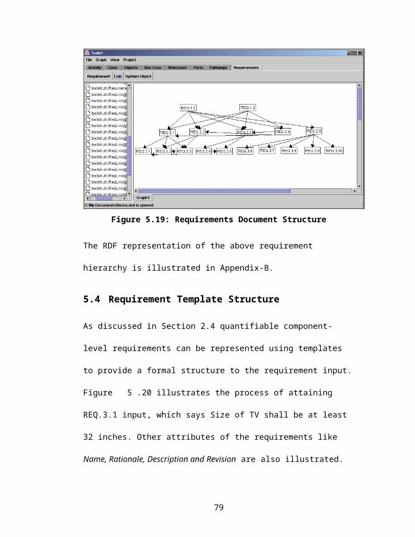
<REVISION Value="Mon Jun 16 14:00:55 EDT 2003" /> <MAPPED_TO Value="TV" /> <Template NO="0" /> <Description Value="The display should be able to be
mounted on the wall" /> </Requirement>- <Requirement ID="REQ.2.3"> <Name Value="High fidelity sound" /> <Rationale Value="Theater experience needs surround
sound capabilities" /> <Verification Value="Demonstration" /> <Comment Value="Detailed agreement between the
customer and the builder" /> <REVISION Value="Mon Jun 16 14:00:55 EDT 2003" /> <MAPPED_TO Value="Speaker" /> <Template NO="0" /> <Description Value="The system shall have a high
fidelity audio system" /> </Requirement>- <Requirement ID="REQ.2.4"> <Name Value="COTS Requirement" /> <Rationale Value="User should be able to go to market
and buy components" /> <Verification Value="Experimental" /> <Comment Value="Detailed agreement between the
customer and the builder" /> <REVISION Value="Mon Jun 16 14:00:55 EDT 2003" /> <MAPPED_TO Value="Home Theater Amplifier" /> <Template NO="0" /> <Description Value="All components will be bought from
the market" /> </Requirement>- <Requirement ID="REQ.2.5"> <Name Value="Connectivity Requirement" /> <Rationale Value="If user buys something from the
market he should be able to connect things together" />
<Verification Value="Demonstration" /> <Comment Value="Detailed agreement between the
customer and the builder" /> <REVISION Value="Mon Jun 16 14:00:55 EDT 2003" /> <MAPPED_TO Value="Home Theater Amplifier" /> <Template NO="0" /> <Description Value="Components of the system shall be
connected to each other" /> </Requirement>- <Requirement ID="REQ.3.1"> <Name Value="Size Requirement on TV" /> <Rationale Value="User definition of Large Display" /> <Verification Value="Demonstration" /> <Comment Value="Component Level Requirement" /> <REVISION Value="Mon Jun 16 14:00:55 EDT 2003" /> <MAPPED_TO Value="TV" />
83

<Template NO="3" OBJECT="TV" SPECIFICATION="Size" SPECLINK="tv1.xml" VALUE1="32" UNITS="inches" />
<Description Value="Size of the TV shall be atleast 32 inches" />
</Requirement>- <Requirement ID="REQ.3.2"> <Name Value="Thickness of TV" /> <Rationale Value="Comes from Wall mountable display
screen" /> <Verification Value="Demonstration" /> <Comment Value="Component Level Requirement" /> <REVISION Value="Mon Jun 16 14:00:55 EDT 2003" /> <MAPPED_TO Value="TV" /> <Template NO="1" OBJECT="TV"
SPECIFICATION="Thickness" SPECLINK="tv1.xml" VALUE1="6" UNITS="inches" />
<Description Value="Thickness of the TV shall not exceed 6 inches" />
</Requirement>- <Requirement ID="REQ.3.2"> <Name Value="Cost of TV" /> <Rationale Value="Splitting of overall Cost of the
System" /> <Verification Value="Analytical" /> <Comment Value="Component Level Requirement" /> <REVISION Value="Mon Jun 16 14:00:55 EDT 2003" /> <MAPPED_TO Value="TV" /> <Template NO="2" OBJECT="TV" SPECIFICATION="Cost"
SPECLINK="tv1.xml" VALUE1="5000" UNITS="USD" /> <Description Value="Cost of the TV shall be less than
5000 USD" /> </Requirement>- <Requirement ID="REQ.3.4"> <Name Value="Cost of the amplifier" /> <Rationale Value="Splitting of overall cost of the
system" /> <Verification Value="Analytical" /> <Comment Value="Component Level Requirement" /> <REVISION Value="Mon Jun 16 14:00:55 EDT 2003" /> <MAPPED_TO Value="Amplifier" /> <Template NO="0" /> <Description Value="Cost of the Amplifier shall be less
than 600 USD" /> </Requirement>- <Requirement ID="REQ.3.5"> <Name Value="Output of the speakers" /> <Rationale Value="Definition of high fidelity sound
system" /> <Verification Value="Demonstration" /> <Comment Value="Component Level Requirement" /> <REVISION Value="Mon Jun 16 14:00:55 EDT 2003" /> <MAPPED_TO Value="Speaker" />
84

<Template NO="5" OBJECT="Speaker" SPECIFICATION="Output" SPECLINK="speaker1.xml" VALUE1="200" VALUE2="350" UNIS="WATTS" />
<Description Value="Output of the Speaker shall lie within 200 watts and 350 watts" />
</Requirement>- <Requirement ID="REQ.3.6"> <Name Value="Audio Connectivity of TV" /> <Rationale Value="Sending sound output to the
amplifier" /> <Verification Value="Demonstration" /> <Comment Value="Component Level Requirement" /> <REVISION Value="Mon Jun 16 14:00:55 EDT 2003" /> <MAPPED_TO Value="n/a" /> <Template NO="8" PORT1="AudioOut" OBJECT1="TV"
PORT2="AudioIn" OBJECT2="Amplifier" /> <Description Value="The AudioOut port of TV shall
connect to AudioIn Port of Amplifier" /> </Requirement>- <Requirement ID="REQ.3.7"> <Name Value="Audio Connectivity of VCR" /> <Rationale Value="Sending sound output to the
amplifier" /> <Verification Value="Demonstration" /> <Comment Value="Component Level Requirement" /> <REVISION Value="Mon Jun 16 14:00:55 EDT 2003" /> <MAPPED_TO Value="n/a" /> <Template NO="8" PORT1="AudioOut" OBJECT1="VCR"
PORT2="AudioIn" OBJECT2="Amplifier" /> <Description Value="The AudioOut port of VCR shall
connect to AudioIn Port of Amplifier" /> </Requirement>- <Requirement ID="REQ.3.8"> <Name Value="Audio Connectivity of DVD Player" /> <Rationale Value="Sending sound output to the
amplifier" /> <Verification Value="Demonstration" /> <Comment Value="Component Level Requirement" /> <REVISION Value="Mon Jun 16 14:00:55 EDT 2003" /> <MAPPED_TO Value="n/a" /> <Template NO="8" PORT1="AudioOut" OBJECT1="DVD"
PORT2="AudioIn" OBJECT2="Amplifier" /> <Description Value="The AudioOut port of DVD shall
connect to AudioIn Port of Amplifier" /> </Requirement>- <Requirement ID="REQ.3.9"> <Name Value="Video Connectivity of VCR" /> <Rationale Value="Sending Video Feed to Television" /> <Verification Value="Demonstration" /> <Comment Value="Component Level Requirement" /> <REVISION Value="Mon Jun 16 14:00:55 EDT 2003" /> <MAPPED_TO Value="n/a" />
85

<Template NO="8" PORT1="VideoOut" OBJECT1="VCR" PORT2="VideoIn" OBJECT2="TV" />
<Description Value="The VideoOut port of VCR shall connect to VideoIn Port of TV" />
</Requirement>- <Requirement ID="REQ.3.10"> <Name Value="Audio Connectivity of Amplifier" /> <Rationale Value="Sending sound output to the
speakers" /> <Verification Value="Demonstration" /> <Comment Value="Component Level Requirement" /> <REVISION Value="Mon Jun 16 14:00:55 EDT 2003" /> <MAPPED_TO Value="n/a" /> <Template NO="8" PORT1="AudioOut"
OBJECT1="Amplifier" PORT2="AudioIn" OBJECT2="Speaker" />
<Description Value="The AudioOut port of Amplifier shall connect to AudioIn Port of Speaker" />
</Requirement> </Project>
86

Appendix-D DAML Representation of the Cable-Port
Ontology
This is the Ontology exported by the Protégé environment using a DAML plugin.
This ontology contains information about a simple cable, its end jacks and the
associated ports. It defines domain restriction on the allowed Jack and Ports
connection through properties converts_to and connects_to.
<rdf:RDF xmlns:rdf ="http://www.w3.org/1999/02/22-rdf-syntax-ns#" xmlns:daml_oil ="http://www.daml.org/2001/03/daml+oil#" xmlns:ontology="http://www.isr.umd.edu/~vmayank#" xmlns:rdfs ="http://www.w3.org/2000/01/rdf-schema#" xmlns ="http://www.isr.umd.edu/~vmayank/ontology#" >
<daml_oil:Class rdf:ID="Port"> </daml_oil:Class> <daml_oil:Class rdf:ID="AudioOutJack"> <rdfs:subClassOf> <daml_oil:Restriction> <daml_oil:toClass rdf:resource="#AudioInJack"/> <daml_oil:onProperty rdf:resource="#converts_to"/> </daml_oil:Restriction> </rdfs:subClassOf> <rdfs:subClassOf rdf:resource="#Jack"/></daml_oil:Class> <daml_oil:ObjectProperty rdf:ID="converts_to"> <daml_oil:domain rdf:resource="#Jack"/> <daml_oil:range rdf:resource="#Jack"/></daml_oil:ObjectProperty> <daml_oil:Class rdf:ID="Jack"> </daml_oil:Class><daml_oil:Class rdf:ID="AudioInPort"> <rdfs:subClassOf> <daml_oil:Restriction> <daml_oil:toClass rdf:resource="#AudioInJack"/> <daml_oil:onProperty rdf:resource="#connects_to"/> </daml_oil:Restriction> </rdfs:subClassOf> <rdfs:subClassOf rdf:resource="#Port"/></daml_oil:Class>
87

<daml_oil:ObjectProperty rdf:ID="connects_to"> <daml_oil:range rdf:resource="#Jack"/> <daml_oil:domain rdf:resource="#Port"/></daml_oil:ObjectProperty> <daml_oil:Class rdf:ID="AudioOutPort"> <rdfs:subClassOf> <daml_oil:Restriction> <daml_oil:toClass rdf:resource="#AudioOutJack"/> <daml_oil:onProperty rdf:resource="#connects_to"/> </daml_oil:Restriction> </rdfs:subClassOf> <rdfs:subClassOf rdf:resource="#Port"/></daml_oil:Class> <daml_oil:Ontology rdf:ID=""> </daml_oil:Ontology> <daml_oil:Class rdf:ID="AudioInJack"> <rdfs:subClassOf> <daml_oil:Restriction> <daml_oil:toClass rdf:resource="#AudioOutJack"/> <daml_oil:onProperty rdf:resource="#converts_to"/> </daml_oil:Restriction> </rdfs:subClassOf> <rdfs:subClassOf rdf:resource="#Jack"/></daml_oil:Class> </rdf:RDF>
88
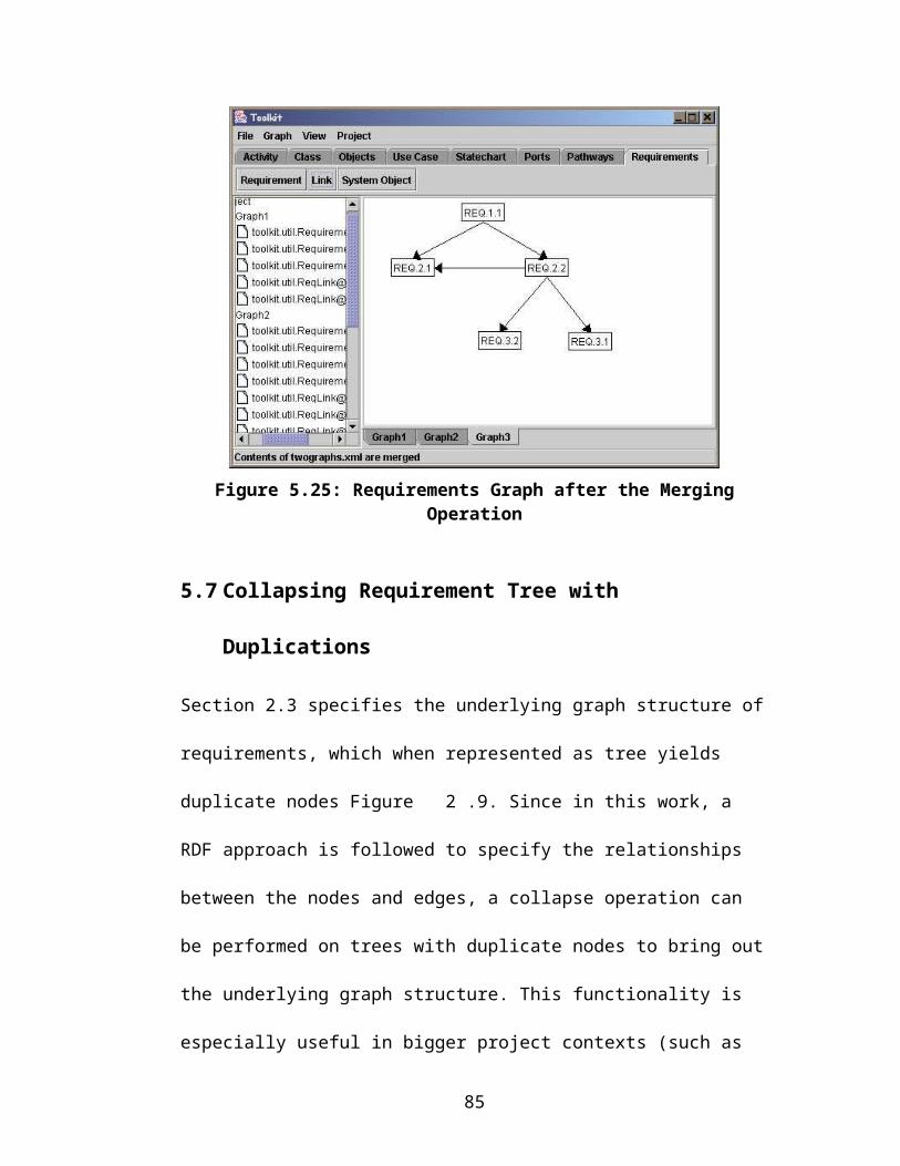
Appendix-E Jess Data Input for the Cable-Port Ontology
Here is the Jess input file, which is generated using the DAMLJessKB plugin to
covert the Ontology into a set of facts (collection of RDF triplets prefixed by the
PropertyValue key), and a set of rules, generated from the instances created in the
GUI. When Rete algorithm is run on the provided set of facts, it checks the cable
configuration and comes out with an assertion whether the cable jacks and
associated ports are consistent as per the ontology definitions or not, and produces
an output informing the results.
;; ====================================================;; ************** Define Initial Facts ****************;; ====================================================(deffacts iniial-condition-from-ontology
(PropertyValue http://www.w3.org/1999/02/22-rdf-syntax-ns#typehttp://www.isr.umd.edu/~vmayank/SimpleOntology.daml#Porthttp://www.daml.org/2001/03/daml+oil#Class)
(PropertyValue http://www.w3.org/1999/02/22-rdf-syntax-ns#typehttp://www.isr.umd.edu/~vmayank/SimpleOntology.daml#AudioOutJackhttp://www.daml.org/2001/03/daml+oil#Class)
(PropertyValue http://www.w3.org/1999/02/22-rdf-syntax-ns#typehttp://www.isr.umd.edu/~vmayank/SimpleOntology.daml#anon2http://www.daml.org/2001/03/daml+oil#Restriction)
(PropertyValue http://www.daml.org/2001/03/daml+oil#toClasshttp://www.isr.umd.edu/~vmayank/SimpleOntology.daml#anon2http://www.isr.umd.edu/~vmayank/SimpleOntology.daml#AudioInJack)
(PropertyValue http://www.daml.org/2001/03/daml+oil#onPropertyhttp://www.isr.umd.edu/~vmayank/SimpleOntology.daml#anon2http://www.isr.umd.edu/~vmayank/SimpleOntology.daml#converts_to)
(PropertyValue http://www.w3.org/2000/01/rdf-schema#subClassOfhttp://www.isr.umd.edu/~vmayank/SimpleOntology.daml#AudioOutJackhttp://www.isr.umd.edu/~vmayank/SimpleOntology.daml#anon2)
(PropertyValue http://www.w3.org/2000/01/rdf-schema#subClassOfhttp://www.isr.umd.edu/~vmayank/SimpleOntology.daml#AudioOutJackhttp://www.isr.umd.edu/~vmayank/SimpleOntology.daml#Jack)
(PropertyValue http://www.w3.org/1999/02/22-rdf-syntax-ns#type
89

http://www.isr.umd.edu/~vmayank/SimpleOntology.daml#converts_tohttp://www.daml.org/2001/03/daml+oil#ObjectProperty)
(PropertyValue http://www.daml.org/2001/03/daml+oil#domainhttp://www.isr.umd.edu/~vmayank/SimpleOntology.daml#converts_tohttp://www.isr.umd.edu/~vmayank/SimpleOntology.daml#Jack)
(PropertyValue http://www.daml.org/2001/03/daml+oil#rangehttp://www.isr.umd.edu/~vmayank/SimpleOntology.daml#converts_tohttp://www.isr.umd.edu/~vmayank/SimpleOntology.daml#Jack)
(PropertyValue http://www.w3.org/1999/02/22-rdf-syntax-ns#typehttp://www.isr.umd.edu/~vmayank/SimpleOntology.daml#Jackhttp://www.daml.org/2001/03/daml+oil#Class)
(PropertyValue http://www.w3.org/1999/02/22-rdf-syntax-ns#typehttp://www.isr.umd.edu/~vmayank/SimpleOntology.daml#AudioInPorthttp://www.daml.org/2001/03/daml+oil#Class)
(PropertyValue http://www.w3.org/1999/02/22-rdf-syntax-ns#typehttp://www.isr.umd.edu/~vmayank/SimpleOntology.daml#anon11http://www.daml.org/2001/03/daml+oil#Restriction)
(PropertyValue http://www.daml.org/2001/03/daml+oil#toClasshttp://www.isr.umd.edu/~vmayank/SimpleOntology.daml#anon11http://www.isr.umd.edu/~vmayank/SimpleOntology.daml#AudioInJack)
(PropertyValue http://www.daml.org/2001/03/daml+oil#onPropertyhttp://www.isr.umd.edu/~vmayank/SimpleOntology.daml#anon11http://www.isr.umd.edu/~vmayank/SimpleOntology.daml#connects_to)
(PropertyValue http://www.w3.org/2000/01/rdf-schema#subClassOfhttp://www.isr.umd.edu/~vmayank/SimpleOntology.daml#AudioInPorthttp://www.isr.umd.edu/~vmayank/SimpleOntology.daml#anon11)
(PropertyValue http://www.w3.org/2000/01/rdf-schema#subClassOfhttp://www.isr.umd.edu/~vmayank/SimpleOntology.daml#AudioInPorthttp://www.isr.umd.edu/~vmayank/SimpleOntology.daml#Port)
(PropertyValue http://www.w3.org/1999/02/22-rdf-syntax-ns#typehttp://www.isr.umd.edu/~vmayank/SimpleOntology.daml#connects_tohttp://www.daml.org/2001/03/daml+oil#ObjectProperty)
(PropertyValue http://www.daml.org/2001/03/daml+oil#rangehttp://www.isr.umd.edu/~vmayank/SimpleOntology.daml#connects_tohttp://www.isr.umd.edu/~vmayank/SimpleOntology.daml#Jack)
(PropertyValue http://www.daml.org/2001/03/daml+oil#domainhttp://www.isr.umd.edu/~vmayank/SimpleOntology.daml#connects_tohttp://www.isr.umd.edu/~vmayank/SimpleOntology.daml#Port)
(PropertyValue http://www.w3.org/1999/02/22-rdf-syntax-ns#typehttp://www.isr.umd.edu/~vmayank/SimpleOntology.daml#AudioOutPorthttp://www.daml.org/2001/03/daml+oil#Class)
(PropertyValue http://www.w3.org/1999/02/22-rdf-syntax-ns#typehttp://www.isr.umd.edu/~vmayank/SimpleOntology.daml#anon19
90
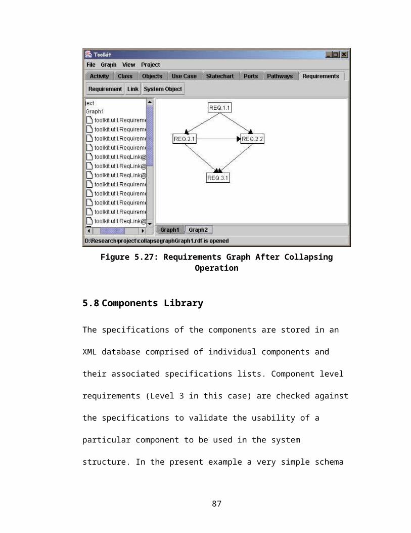
http://www.daml.org/2001/03/daml+oil#Restriction)
(PropertyValue http://www.daml.org/2001/03/daml+oil#toClasshttp://www.isr.umd.edu/~vmayank/SimpleOntology.daml#anon19http://www.isr.umd.edu/~vmayank/SimpleOntology.daml#AudioOutJack)
(PropertyValue http://www.daml.org/2001/03/daml+oil#onPropertyhttp://www.isr.umd.edu/~vmayank/SimpleOntology.daml#anon19http://www.isr.umd.edu/~vmayank/SimpleOntology.daml#connects_to)
(PropertyValue http://www.w3.org/2000/01/rdf-schema#subClassOfhttp://www.isr.umd.edu/~vmayank/SimpleOntology.daml#AudioOutPorthttp://www.isr.umd.edu/~vmayank/SimpleOntology.daml#anon19)
(PropertyValue http://www.w3.org/2000/01/rdf-schema#subClassOfhttp://www.isr.umd.edu/~vmayank/SimpleOntology.daml#AudioOutPorthttp://www.isr.umd.edu/~vmayank/SimpleOntology.daml#Port)
(PropertyValue http://www.w3.org/1999/02/22-rdf-syntax-ns#typehttp://www.isr.umd.edu/~vmayank/SimpleOntology.daml#AudioInJackhttp://www.daml.org/2001/03/daml+oil#Class)
(PropertyValue http://www.w3.org/1999/02/22-rdf-syntax-ns#typehttp://www.isr.umd.edu/~vmayank/SimpleOntology.daml#anon24http://www.daml.org/2001/03/daml+oil#Restriction)
(PropertyValue http://www.daml.org/2001/03/daml+oil#toClasshttp://www.isr.umd.edu/~vmayank/SimpleOntology.daml#anon24http://www.isr.umd.edu/~vmayank/SimpleOntology.daml#AudioOutJack)
(PropertyValue http://www.daml.org/2001/03/daml+oil#onPropertyhttp://www.isr.umd.edu/~vmayank/SimpleOntology.daml#anon24http://www.isr.umd.edu/~vmayank/SimpleOntology.daml#converts_to)
(PropertyValue http://www.w3.org/2000/01/rdf-schema#subClassOfhttp://www.isr.umd.edu/~vmayank/SimpleOntology.daml#AudioInJackhttp://www.isr.umd.edu/~vmayank/SimpleOntology.daml#anon24)
(PropertyValue http://www.w3.org/2000/01/rdf-schema#subClassOfhttp://www.isr.umd.edu/~vmayank/SimpleOntology.daml#AudioInJackhttp://www.isr.umd.edu/~vmayank/SimpleOntology.daml#Jack)
(PropertyValue http://www.w3.org/1999/02/22-rdf-syntax-ns#typehttp://www.isr.umd.edu/~vmayank/SimpleOntology.damlhttp://www.daml.org/2001/03/daml+oil#Ontology))
;; ====================================================;; ************* Reset the known facts ****************;; ====================================================(reset)
;; ====================================================;; Rule 1: This rule if fired accounts for the fact ;; that the cable has correct jacks at its two ends and ;; produces such an output;; ====================================================
91

(defrule allowed-jack-config(PropertyValue http://www.daml.org/2001/03/daml+oil#toClass?anon;; ====================================================;; This Jack A instance is generated programmatically ;; using the Java API;; =========+==========================================http://www.isr.umd.edu/~vmayank/SimpleOntology.daml#AudioOutJack)
(PropertyValue http://www.daml.org/2001/03/daml+oil#onProperty?anon http://www.isr.umd.edu/~vmayank/SimpleOntology.daml#converts_to)
(PropertyValue http://www.w3.org/2000/01/rdf-schema#subClassOf;; ====================================================;; This Jack B instance is generated programmatically ;; using the Java API;; =========+==========================================http://www.isr.umd.edu/~vmayank/SimpleOntology.daml#AudioInJack?anon)
(PropertyValue http://www.w3.org/1999/02/22-rdf-syntax-ns#type?anon http://www.daml.org/2001/03/daml+oil#Restriction)=>(printout t "Cable jacks are consistent with ontology definition" crlf)
) ;; end defrule construct
;; ====================================================;; Rule 2: This rule if fired accounts for the fact ;; that the cable does not have correct jacks at its ;; two ends as per the Ontology definition and produces ;; such an Output;; ====================================================(defrule not-allowed-jack-config(not (and (PropertyValue http://www.daml.org/2001/03/daml+oil#toClass?anon;; ====================================================;; This Jack A instance is generated programmatically ;; using the Java API;; =========+==========================================http://www.isr.umd.edu/~vmayank/SimpleOntology.daml#AudioOutJack)
(PropertyValue http://www.daml.org/2001/03/daml+oil#onProperty?anon http://www.isr.umd.edu/~vmayank/SimpleOntology.daml#converts_to)
(PropertyValue http://www.w3.org/2000/01/rdf-schema#subClassOf;; ====================================================;; This Jack B instance is generated programmatically ;; using the Java API;; =========+==========================================http://www.isr.umd.edu/~vmayank/SimpleOntology.daml#AudioInJack?anon)
92

(PropertyValue http://www.w3.org/1999/02/22-rdf-syntax-ns#type?anon http://www.daml.org/2001/03/daml+oil#Restriction)))=>(printout t "Cable jacks not consistent with ontology definition" crlf)) ; end defrule construct
;; ====================================================;; Rule 3: This rule if fired accounts for the fact ;; that the Jack A is properly Connected to Port A as ;; per the Ontology definition;; ====================================================(defrule allowed-jacka-porta-config(PropertyValue http://www.w3.org/1999/02/22-rdf-syntax-ns#type?anon http://www.daml.org/2001/03/daml+oil#Restriction)
(PropertyValue http://www.daml.org/2001/03/daml+oil#toClass?anon;; ====================================================;; This Jack A instance is generated programmatically ;; using the Java API;; =========+==========================================http://www.isr.umd.edu/~vmayank/SimpleOntology.daml#AudioOutJack)
(PropertyValue http://www.daml.org/2001/03/daml+oil#onProperty?anon http://www.isr.umd.edu/~vmayank/SimpleOntology.daml#connects_to)
(PropertyValue http://www.w3.org/2000/01/rdf-schema#subClassOf;; ====================================================;; This Port A instance is generated programmatically ;; using the Java API;; =========+==========================================http://www.isr.umd.edu/~vmayank/SimpleOntology.daml#AudioOutPort?anon)=>(printout t "Jack A consistent with Port A as per ontology definition" crlf)) ;; end defrule construct
;; ====================================================;; Rule 4: This rule if fired accounts for the fact ;; that the Jack A is not properly Connected to Port A ;; as per the Ontology definition and produces the ;; error message;; ====================================================(defrule not-allowed-jacka-porta-config(not (and(PropertyValue http://www.w3.org/1999/02/22-rdf-syntax-ns#type?anon http://www.daml.org/2001/03/daml+oil#Restriction)
(PropertyValue http://www.daml.org/2001/03/daml+oil#toClass?anon;; ====================================================;; This Jack A instance is generated programmatically ;; using the Java API
93

;; =========+==========================================http://www.isr.umd.edu/~vmayank/SimpleOntology.daml#AudioOutJack)
(PropertyValue http://www.daml.org/2001/03/daml+oil#onProperty?anon http://www.isr.umd.edu/~vmayank/SimpleOntology.daml#connects_to)
(PropertyValuehttp://www.w3.org/2000/01/rdf-schema#subClassOf;; ====================================================;; This Port A instance is generated programmatically ;; using the Java API;; =========+==========================================http://www.isr.umd.edu/~vmayank/SimpleOntology.daml#AudioOutPort?anon)))=>(printout t crlf "Jack A not consistent with Port A as per ontology definition" crlf)(printout t "If you are sure that cable is compatible with the port try reversing the cable" crlf)) ;; end defrule construct
;; ====================================================;; Rule 5: This rule if fired accounts for the fact ;; that the Jack B is properly Connected to Port B as ;; per the Ontology definition and produces a message;; ====================================================(defrule allowed-jackb-portb-config(PropertyValue http://www.w3.org/1999/02/22-rdf-syntax-ns#type?anon http://www.daml.org/2001/03/daml+oil#Restriction)
(PropertyValue http://www.daml.org/2001/03/daml+oil#toClass?anon;; ====================================================;; This Jack B instance is generated programmatically ;; using the Java API;; =========+==========================================http://www.isr.umd.edu/~vmayank/SimpleOntology.daml#AudioInJack)
(PropertyValue http://www.daml.org/2001/03/daml+oil#onProperty?anon http://www.isr.umd.edu/~vmayank/SimpleOntology.daml#connects_to)
(PropertyValue http://www.w3.org/2000/01/rdf-schema#subClassOf;; ====================================================;; This Port B instance is generated programmatically ;; using the Java API;; =========+==========================================http://www.isr.umd.edu/~vmayank/SimpleOntology.daml#AudioInPort?anon)=>(printout t "Jack B consistent with Port B as per ontology definition" crlf)) ;; end defrule construct
;; ====================================================
94

;; Rule 6: This rule if fired accounts for the fact ;; that the Jack B is not properly Connected to Port B ;; as per the Ontology definition and produces an error ;; message;; ====================================================(defrule not-allowed-jackb-portb-config(not (and(PropertyValue http://www.w3.org/1999/02/22-rdf-syntax-ns#type?anon http://www.daml.org/2001/03/daml+oil#Restriction)
(PropertyValue http://www.daml.org/2001/03/daml+oil#toClass?anon;; ====================================================;; This Jack B instance is generated programmatically ;; using the Java API;; =========+==========================================http://www.isr.umd.edu/~vmayank/SimpleOntology.daml#AudioInJack)
(PropertyValue http://www.daml.org/2001/03/daml+oil#onProperty?anon http://www.isr.umd.edu/~vmayank/SimpleOntology.daml#connects_to)
(PropertyValue http://www.w3.org/2000/01/rdf-schema#subClassOf;; ====================================================;; This Port B instance is generated programmatically ;; using the Java API;; =========+==========================================http://www.isr.umd.edu/~vmayank/SimpleOntology.daml#AudioInPort?anon)))=>(printout t crlf "Jack B not consistent with Port B as per ontology definition" crlf)(printout t "If you are sure that cable is compatible with the port try reversing the cable" crlf)) ;; end defrule construct
;; run the Rete on the above facts and rules(run)
95
REFERENCES
[1] Unified Modeling Language (UML). (2003, Aug.). [Online]. Available: http://www.omg.org/uml
[2] H. Lykins. S. Friedenthal. and A. Meilich. (2001, Oct.).Adapting UML for an Object Oriented Systems Engineering Method (OOSEM). Presented at 2001 Incose Chesapeake Chapter Meeting. [Online]. Available: http://www.incose.org/chesapek/meetings/Adapting_UML_for_an_OOSEM.doc
[3] J. Adams. (2003, Apr). Global Precipitation Measurement [Online]. Available: http://gpm.gsfc.nasa.gov/index.html
[4] Microsoft Visio. (2003, July). [Online]. Available: http://www.microsoft.com/office/visio/
[5] Rational Rose. (2003, July). [Online]. Available: http://www.rational.com/ products/rose/
[6] EDS Slate. (2003, July). [Online]. Available: http://www.eds.com/products/ plm/teamcenter/slate/
[7] Telelogic Doors. (2003, July). [Online]. Available: http://www.telelogic.com/products/doorsers/doors/
[8] Ilog Cplex. (2003, July). [Online]. Available: http://www.cplex.com
[9] Mathworks Matlab. (2003, July). [Online]. Available: http://www.mathworks.com/products/matlab/
[10] Arena. (2003, July). [Online]. Available: http://www.arenasimulation.com/
[11] K. Kronlog, Method Integration: Concepts and Case Studies. John-Wiley and Sons, 1993
[12] S. Melnik. and S. Decker. (2000, Sep). A Layered Approach to Information Modeling and Interoperability on the Web. Presented at Proc. ECDL'00 Workshop on the Semantic Web, Lisbon, Portugal. [Online] Available: http://www-db.stanford.edu/~melnik/pub/sw00
[13] W3C Resource Description Framework (RDF). (2003, July). [Online]. Available: http://www.w3.org/RDF
[14] Darpa Agent Markup Language (DAML). (2003, July). [Online]. Available: http://www.daml.org
96

[15] T. Berners-Lee, J. Hendler, and O.Lassila, “The Semantic Web,” Scientific American, pp 35-43, May. 2001.
[16] J. Hendler, “Agents and the Semantic Web,” IEEE Intelligent Systems, vol. 16(2), pp. 30-37, Mar. /Apr. 2001.
[17] D. Fensel, F. van Harmele, I. Horrocks, D. L. McGuinness, and P. F. Patel-Schneider, “OIL: An Ontology Infrastructure for the Semantic Web,” IEEE Intelligent Systems, vol. 16(2), pp. 38-45, Mar. /Apr. 2001.
[18] M. Gruniger and J. Lee, “Ontology Applications and Design,” Communications of the ACM, vol. 45(2), pp. 39-41, Feb. 2002.
[19] S. A. Selberg. and M. A. Austin. (2003, Apr.). Requirements Engineering and the Semantic Web. ISR. University of Maryland. College Park. MD. [Online]. Available: http://techreports.isr.umd.edu/TechReports/ISR/2003/ TR_2003-20/TR_2003-20.phtml
[20] M. E. C. Hull, K. Jackson, and A. J. J. Dick, Requirements Engineering. Springer 2002
[21] Microsoft Word. (2003, July). [Online]. Available: http://www.microsoft.com/office/word
[22] W3C Extensible Markup Language (XML). (2003, July). [Online]. Available: http://www.w3.org/XML/
[23] W3C Extensible Stylesheet Language Family (XSLT). (2003, July). [Online]. Available: http://www.w3.org/Style/XSL
[24] Sun Microsystems Java. (2003, July). [Online]. Available: http://java.sun.com
[25] The Apache XML Project Xerces. (2003, July). [Online]. Available: http://xml.apache.org
[26] Hewlett-Packard RDQL – RDF Data Query Language. (2003, July). [Online]. Available: http://www.hpl.hp.com/semweb/rdql.htm
[27] Hewlett-Packard Jena – A Java API for RDF. (2003, Apr.). [Online]. Available: http://www.hpl.hp.com/semweb/
[28] T. Kamada and S. Kawai, “A General Framework for Visualizing Abstract Objects an Relations,” ACM Transaction on Graphics, vol. 10(1), pp. 1-39, Jan. 1991.
[29] W3C DOM – Document Object Model. (2003, July). [Online]. Available: http://www.w3.org/DOM/
97

[30] D. Megginson. Simple API for XML (SAX). (2003, July). [Online]. Available: http://www.saxproject.org
[31] W3C RDF Validation Service. (2003, July). [Online]. Available: http://www.w3.org/RDF/Validator
[32] M. A. Austin and B. A. Frankpitt, “Systems Engineering Principles,” class notes for ENSE 621 and ENPM 641, University of Maryland, College Park, MD, Fall 2001
[33] W3C Web Ontology Language (OWL). (2003, July). [Online]. Available: http://www.w3.org/TR/owl-ref/
[34] Stanford Medical Informatics Protégé Ontology Editor and Knowledge Acquisition System. (2003, June). [Online]. Available: http://protege.stanford.edu
[35] SRI International DAML+OIL Plugin for Protégé 2000. (2003, July). [Online]. Available: http://www.ai.sri.com/daml/DAML+OIL-plugin/ index.htm
[36] Annotated DAML+OIL Ontology Markup. (2001, Mar.). [Online]. Available: http://www.daml.org/2001/03/daml+oil-walkthru.html
[37] Netscape. (2003, July). [Online]. Available: http://www.netscape.com
[38] Sandia National Laboratories Jess – The Expert System Shell for the Java Platform. (2003, July). [Online]. Available: http://herzberg.ca.sandia.gov/ jess/
[39] Drexel University DAMLJessKB. (2003, June). [Online]. Available: http://edge.mcs.drexel.edu/assemblies/software/damljesskb/damljesskb.html
[40] J. Kopena and W. C. Regli, “DAMLJessKB: A Tool for Reasoning with the Semantic Web,” IEEE Intelligent Systems, vol. 18(3), pp. 74-77, May / June 2003.
[41] C. L. Forgy, “Rete: A Fast Algorithm for the Many Pattern/ Many Object Pattern Match Problem,” Artificial Intelligence, vol. 19, pp. 17-37, 1982
[42] H. P. Frisch. AP 233 Systems Engineering (2003, May). [Online] Available: http://step.jpl.nasa.gov/AP233/
[43] D. Oliver, “AP233 – INCOSE Status Report,” in Incose Insight, vol. 5(3), Oct. 2002.
98
[44] D. Muller. Requirements Engineering Knowledge Management based on STEP AP233. (2003, July). [Online]. Available: http://www.sgi.co.kr/ solutions/catia/download/immersive/step2000_seminor/step_ap233.pdf
[45] Vitech Corp CORE. (2003, July). [Online]. Available: http://www.vitechcorp.com/productline.html
[46] M. A. Austin. Summer Systems Engineering Project. (2003, July). [Online]. Available: http://www.isr.umd.edu/~austin/summer-se-project.html
[47] P. Eades and R. Tamassia, “Algorithms for Drawing Graphs: An Annotated Bibliography,” Department of Computer Science, Brown University, Providence, RI Tech. Rep. CS-89-09, Feb. 1989.
[48] R. Tamassaia, G. Battista, and C. Batini, “Automatic Graph Drawing and Readability of Diagrams,” IEEE Transactions on Systems, Machines and Cybernetics, vol. 18(1), pp. 61-79, Jan. 1988.
[49] I. Herman, “Graph Visualization and Navigation in Information Visualization: A Survey,” IEEE Transactions on Visualization and Computer Graphics, vol. 6(1), pp. 24-43, Jan.-Mar. 2000.
[50] Jgraph. (2003, July). [Online]. Available: http://jgraph.sourceforge.net
[51] C. Mccreary. Drawing Graphs with VGJ, Department of Computer Science and Software Engineering. (1998, Apr.). [Online]. Available: http://www.eng.auburn.edu/department/cse/research/graph_drawing/graph_drawing.html
[52] ILOG Views Graph Layout. (2003, July). [Online]. Available: http://www.ilog.com/products/views/graphlayout/
99