br-ov-b hauck b-f-g-h-k bracket coupling kit installation
TRANSCRIPT

SCC Inc. Installation Instructions
Document No. CPBK-9300 February 20, 2019
SCC Inc.
BR-OV-B…
Product Description
A BR-OV-B… bracket / coupling kit reliably mounts any Hauck B, F, G, H, or K oil valve to a
Siemens SQM… actuator.
Components Supplied
Figure 1 shows the components supplied with a BR-OV-B… bracket / coupling kit:
Figure 1: Components Supplied with a BR-OV-B… Bracket / Coupling Kit
1. Shaft coupling
2. (4) hex standoffs
3. Actuator mounting bracket
4. (2) valve mounting brackets
5. (4) 1/4”-20 x 3/4” flat socket head cap
screws
6. (4) 1/4”-20 x 1” hex head cap screws
7. (4) 1/4” internal tooth lock washers
8. (2) or (4) M5 x 12mm thread-forming screws
9. M8 x 18mm hex head cap screw (BR-OV-B-4-
1 or BR-OV-B-7-2 for SQM5… actuator only)
10. M8 split lock washer (BR-OV-B-4-1 or BR-OV-
B-7-2 for SQM5… actuator only)
* Component varies depending on the BR-OV-B… bracket / coupling kit. Image shown in
Figure 1 may not be representative of actual component.

Installation Instructions BR Series
Document No. CPBK-9300
Page 2 SCC Inc.
Recommended Installation Tools
The following tools are recommended for installing the BR-OV-B… bracket / coupling kit:
• Crescent wrench
• 7/16” open-end wrench
• File
• Purple Loctite
• 5/32” hex key
• 8mm socket with 6” ratchet extension
(1/4” drive)
• 1/4” drive ratchet
• 13mm wrench
• 8mm wrench
• 1/4” hex key
Installation Procedure
1. Using a crescent wrench, remove the acorn nut and washer from the top of the valve
stem. The cap and washer can be discarded.
Figure 2: Acorn Nut and Washer Removal
2. Using the 7/16” wrench and crescent wrench, remove the four long screws that extend
through the valve body with nuts on the bottom side of the valve. These screws are
highlighted in red in Figure 3 below. Keep the screws, flat washers, lock washers, and
hex nuts for the next step.
B and F Valves G and K Valves H Valves
Figure 3: Valve Screw Removal
Remove acorn
nut and washer
BR Series Installation Instructions
Document No. CPBK-9300
SCC Inc. Page 3
Installation Procedure (continued)
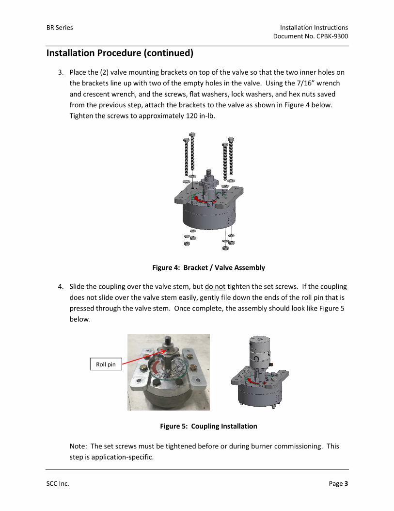
3. Place the (2) valve mounting brackets on top of the valve so that the two inner holes on
the brackets line up with two of the empty holes in the valve. Using the 7/16” wrench
and crescent wrench, and the screws, flat washers, lock washers, and hex nuts saved
from the previous step, attach the brackets to the valve as shown in Figure 4 below.
Tighten the screws to approximately 120 in-lb.
Figure 4: Bracket / Valve Assembly
4. Slide the coupling over the valve stem, but do not tighten the set screws. If the coupling
does not slide over the valve stem easily, gently file down the ends of the roll pin that is
pressed through the valve stem. Once complete, the assembly should look like Figure 5
below.
Figure 5: Coupling Installation
Note: The set screws must be tightened before or during burner commissioning. This
step is application-specific.
Roll pin
Installation Instructions BR Series
Document No. CPBK-9300
Page 4 SCC Inc.
Installation Procedure (continued)
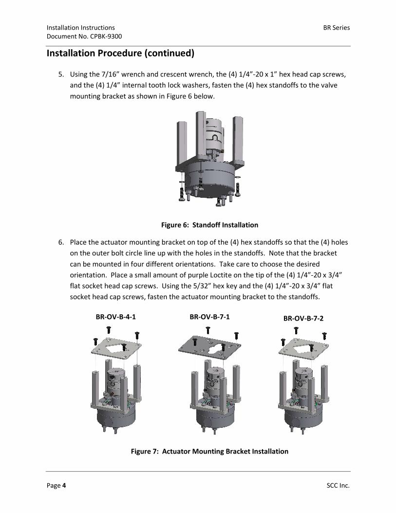
5. Using the 7/16” wrench and crescent wrench, the (4) 1/4”-20 x 1” hex head cap screws,
and the (4) 1/4” internal tooth lock washers, fasten the (4) hex standoffs to the valve
mounting bracket as shown in Figure 6 below.
Figure 6: Standoff Installation
6. Place the actuator mounting bracket on top of the (4) hex standoffs so that the (4) holes
on the outer bolt circle line up with the holes in the standoffs. Note that the bracket
can be mounted in four different orientations. Take care to choose the desired
orientation. Place a small amount of purple Loctite on the tip of the (4) 1/4”-20 x 3/4”
flat socket head cap screws. Using the 5/32” hex key and the (4) 1/4”-20 x 3/4” flat
socket head cap screws, fasten the actuator mounting bracket to the standoffs.
BR-OV-B-4-1
BR-OV-B-7-1
BR-OV-B-7-2
Figure 7: Actuator Mounting Bracket Installation
BR Series Installation Instructions
Document No. CPBK-9300
SCC Inc. Your feedback is important to us. If you have Document No. CPBK-9300 1250 Lunt Avenue comments about this document, please send them Country of Origin: US
Elk Grove Village, IL 60007 to [email protected] Page 5
U.S.A.
Installation Procedure (continued)
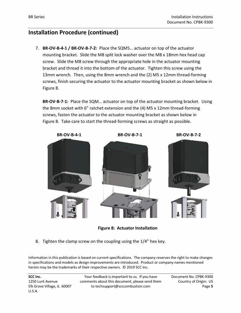
7. BR-OV-B-4-1 / BR-OV-B-7-2: Place the SQM5… actuator on top of the actuator
mounting bracket. Slide the M8 split lock washer over the M8 x 18mm hex head cap
screw. Slide the M8 screw through the appropriate hole in the actuator mounting
bracket and thread it into the bottom of the actuator. Tighten this screw using the
13mm wrench. Then, using the 8mm wrench and the (2) M5 x 12mm thread-forming
screws, finish securing the actuator to the actuator mounting bracket as shown below in
Figure 8.
BR-OV-B-7-1: Place the SQM… actuator on top of the actuator mounting bracket. Using
the 8mm socket with 6” ratchet extension and the (4) M5 x 12mm thread-forming
screws, fasten the actuator to the actuator mounting bracket as shown below in
Figure 8. Take care to start the thread-forming screws as straight as possible.
BR-OV-B-4-1 BR-OV-B-7-1 BR-OV-B-7-2
Figure 8: Actuator Installation
8. Tighten the clamp screw on the coupling using the 1/4” hex key.
Information in this publication is based on current specifications. The company reserves the right to make changes
in specifications and models as design improvements are introduced. Product or company names mentioned
herein may be the trademarks of their respective owners. © 2019 SCC Inc.