brampton animal services 475 chrysler …...city of brampton brampton animal services 475 chrysler...
TRANSCRIPT

CITY OF BRAMPTON
BRAMPTON ANIMAL SERVICES
475 CHRYSLER DRIVE
POWER SERVICE, GENERATOR REPLACEMENT AND EQUIPMENT
UPGRADES
APRIL 2019
SUBMITTED BY:
Phone: 905 274-7556 Fax: 905 274-5382 2902 S. Sheridan Way, Ste. 300, Oakville, ON. L6J 7L6
www.moon-matz.com

CITY OF BRAMPTON 00000 BRAMPTON ANIMAL SERVICES CONTENTS 475 CHRYSLER DRIVE, BRAMPTON Page 1
DIVISION 01 – GENERAL Section 01005 – General Requirements Section 01330 – Submittal Requirements Section 01450 – Quality Control Section 01610 – Basic Product Requirements Section 01740 – Cleaning Section 01770 – Project Closeout DIVISION 02 – SITE WORK Section 02316 – Excavation Section 02323 – Backfilling DIVISION 03 – CONCRETE Section 03100 – Concrete Formwork and Falsework Section 03200 – Concrete Reinforcement Section 03300 – Cast-in-place Concrete DIVISION 15 – MECHANICAL Section 15010 – Basic Mechanical Requirements Section 15050 – Basic Mechanical Materials and Methods Section 15060 – Pipes, Hangers and Supports Section 15075 – Mechanical Identification Section 15730 – HVAC Equipment Section 15800 – Walk-In Freezer Section 15990 – Start-Up and Performance Testing Section 15995 – Commissioning DIVISION 16 – ELECTRICAL Section 16010 – Electrical General Provisions Section 16100 – Electrical Basic Materials and Methods Section 16175 – Underground Distribution Section 16230 – Power Generation – Natural Gas Section 16231 – Installation of Natural Gas Generator Section 16232 – Temporary Diesel Power Generation Section 16400 – Electrical Distribution System Section 16500 – Lighting Equipment Section 16700 – Fire Alarm System Section 16950 – Commissioning and Field Quality Control APPENDIX A - City of Brampton standard detail L110 Temporary Tree Protection Fencing
CITY OF BRAMPTON 00000 BRAMPTON ANIMAL SERVICES CONTENTS 475 CHRYSLER DRIVE, BRAMPTON Page 2
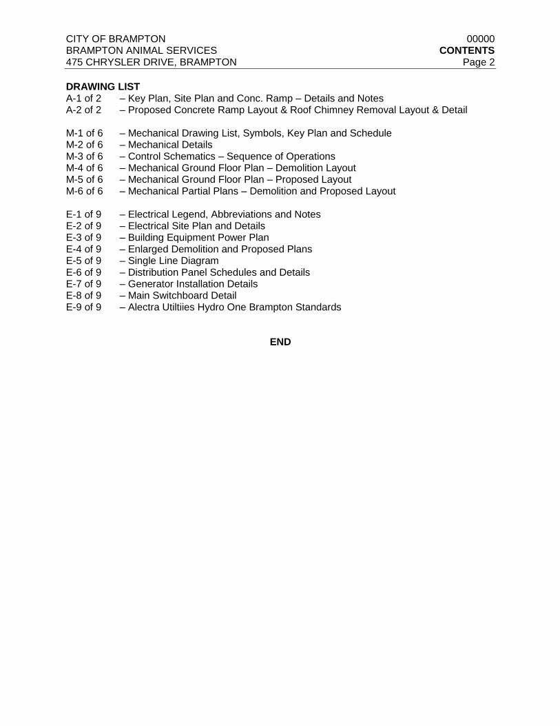
DRAWING LIST A-1 of 2 – Key Plan, Site Plan and Conc. Ramp – Details and Notes A-2 of 2 – Proposed Concrete Ramp Layout & Roof Chimney Removal Layout & Detail M-1 of 6 – Mechanical Drawing List, Symbols, Key Plan and Schedule M-2 of 6 – Mechanical Details M-3 of 6 – Control Schematics – Sequence of Operations M-4 of 6 – Mechanical Ground Floor Plan – Demolition Layout M-5 of 6 – Mechanical Ground Floor Plan – Proposed Layout M-6 of 6 – Mechanical Partial Plans – Demolition and Proposed Layout E-1 of 9 – Electrical Legend, Abbreviations and Notes E-2 of 9 – Electrical Site Plan and Details E-3 of 9 – Building Equipment Power Plan E-4 of 9 – Enlarged Demolition and Proposed Plans E-5 of 9 – Single Line Diagram E-6 of 9 – Distribution Panel Schedules and Details E-7 of 9 – Generator Installation Details E-8 of 9 – Main Switchboard Detail E-9 of 9 – Alectra Utiltiies Hydro One Brampton Standards
END

CITY OF BRAMPTON SECTION 01005 BRAMPTON ANIMAL SERVICES GENERAL REQUIREMENTS 475 CHRYSLER DRIVE, BRAMPTON Page 1
1.0 GENERAL
1.1 RELATED REQUIREMENTS
1.1.1 General Conditions
1.1.2 Ontario Building Code (OBC) current edition, including all amendments up to bid closing
date.
1.1.3 Province of Ontario Occupational Health and Safety Act and Regulations for
Construction Sites: All work shall be in accordance with the latest edition of the Province
Of Ontario Occupational Health and Safety Act and Regulations for Construction
Projects.
1.2 PROJECT COORDINATION
1.2.1 Co-ordinate progress of the Work, progress schedules, submittals, use of site, temporary
utilities and construction facilities.
1.2.2 Co-ordinate the work of all trades so work proceeds as planned and equipment functions
properly.
1.3 CUTTING AND PATCHING
1.3.1 Submit written request in advance of cutting or alteration which affects:
.1 Structural integrity of any element of the Project.
.2 Integrity of weather exposed or moisture resistant elements.
.3 Efficiency, maintenance, or safety of any operational element.
.4 Visual qualities of sight exposed elements.
.5 Work of Owner or separate contractor.
1.4 INSPECTION
1.4.1 Inspect existing conditions, including elements subject to damage or movement during
cutting and patching.
1.4.2 After uncovering, inspect conditions affecting performance of work.
1.4.3 Beginning of cutting or patching means acceptance of existing conditions.
1.5 EXECUTION
1.5.1 Perform cutting, fitting, patching and repairs to complete the Work.
1.5.2 Remove and replace defective and non-conforming work.
1.5.3 Provide openings in non-structural elements of Work for penetrations of mechanical and
electrical work.
1.5.4 Perform work to avoid damage to other work. Co-ordinate between all trades.
1.5.5 Prepare surfaces to receive patching and finishing.

CITY OF BRAMPTON SECTION 01005 BRAMPTON ANIMAL SERVICES GENERAL REQUIREMENTS 475 CHRYSLER DRIVE, BRAMPTON Page 2
1.5.6 Employ original installer to perform cutting and patching for weather-exposed and
moisture-resistant elements, and sight-exposed surfaces.
1.5.7 Cut rigid materials using power saw or core drill. Pneumatic or impact tools not allowed.
1.5.8 Restore work with new products in accordance with Contract Documents.
1.5.9 Fit work airtight to pipes, sleeves, ducts, conduit, and other penetrations through
surfaces.
1.5.10 At penetration of fire-rated wall, ceiling, or floor construction, completely seal voids with
fire rated material full thickness of the construction element.
1.5.11 Refinish surfaces to match adjacent finishes; for continuous surfaces refinish to nearest
intersection; for an assembly, refinish entire unit.
1.6 PROJECT MEETINGS
1.6.1 Contractor to Schedule and administer project progress meetings throughout the
progress of the work.
1.6.2 Distribute written notice of each meeting 4 days in advance of meeting date to
Consultant and Owner’s representatives.
1.6.3 Space will be provided on site for meetings. The Contractor to make arrangements for
meetings.
1.6.4 Record the minutes. Include significant proceedings and decisions. Identify the "Action
By" parties.
1.6.5 Reproduce and distribute copies of minutes within 3 days after each meeting and
transmit to meeting participants and affected parties not in attendance.
1.7 RECORD DRAWINGS
1.7.1 On completion of Work and prior to final inspection, submit record documents to
Consultant. Refer to section 01770 – Closeout Documents, for submission format.
1.8 SCHEDULES
1.8.1 Submit the following schedules
.1 Construction Progress Schedule.
.2 Submittal Schedule for Shop Drawings, Product Data and Samples.
1.9 SCHEDULE FORMAT
1.9.1 Prepare schedule in the form of a horizontal bar chart.
1.9.2 Provide a separate bar for each trade or operation.
1.9.3 Provide horizontal time scale identifying the first work day of each week.
1.9.4 Format for listings: The chronological order of the start of each item of work.

CITY OF BRAMPTON SECTION 01005 BRAMPTON ANIMAL SERVICES GENERAL REQUIREMENTS 475 CHRYSLER DRIVE, BRAMPTON Page 3
1.10 SCHEDULE SUBMISSION
1.10.1 Submit initial schedules within 7 days after award of Contract.
1.10.2 Submit 2 opaque reproduction, plus 2 copies to be retained by the Consultant.
1.10.3 Consultant will review schedule and return reviewed copy within 5 days after receipt.
1.10.4 Resubmit finalized schedule within 7 days after return of reviewed copy.
1.11 CONSTRUCTION FACILITIES AND TEMPORARY CONTROLS
1.11.1 Provide construction facilities and temporary controls in order to execute the work
expeditiously.
1.11.2 Remove from site all such work after use.
1.12 DUST TIGHT SCREENS
1.12.1 Provide dust tight screens or partitions to localize dust generating activities, and for the
protection of workers, finished areas of Work and the public.
1.12.2 Maintain and relocate protection until such Work is complete.
1.13 SITE STORAGE AND LOADING
1.13.1 Confine the Work and the operations of employees to limits indicated by the Contract
Documents. Do not unreasonably encumber the premises with Products.
1.13.2 Do not load or permit to be loaded any part of the Work with a weight or force that will
endanger the Work.
1.14 SANITARY FACILITIES
1.14.1 Existing facilities as designated may be used during the construction period.
1.15 WATER SUPPLY
1.15.1 The Owner will provide a continuous supply of potable water for construction use.
1.16 CONCEALMENT
1.16.1 In finished areas, conceal pipes, ducts and wiring in floors, walls and ceilings, except
where indicated otherwise.
1.16.2 Before installation, inform the Consultant if there is a contradictory situation. Install as
directed by Consultant.
1.17 FINAL DOCUMENTS
1.17.1 Collect reviewed submittals and assemble documents executed by Subcontractors,
suppliers, and manufacturers.
1.17.2 Submit material prior to final Application for Payment.
1.17.3 Submit operation and maintenance data, record (as-built) drawings.
1.17.4 Provide warranties fully executed and notarized.

CITY OF BRAMPTON SECTION 01005 BRAMPTON ANIMAL SERVICES GENERAL REQUIREMENTS 475 CHRYSLER DRIVE, BRAMPTON Page 4
1.17.5 Submit a final statement of accounting giving total adjusted Contract Price, previous
payments, and monies remaining due.
1.17.6 Consultant will issue a final change order reflecting approved adjustments to Contract
Price not previously made.
END OF SECTION

CITY OF BRAMPTON SECTION 01330 BRAMPTON ANIMAL SERVICES SUBMITTAL REQUIREMENTS 475 CHRYSLER DRIVE, BRAMPTON Page 1
1.0 GENERAL
1.1 SECTION INCLUDES
1.1.1 Administrative
1.1.2 Shop drawings and product data.
1.1.3 Samples.
1.1.4 Operating and Maintenance Manuals
1.2 ADMINISTRATIVE
1.2.1 Submit after contract award submittals within ten (10) business days of receipt of
submittal information and in an orderly sequence so as to not cause delay in Work.
Failure to submit in ample time is not considered sufficient reason for an extension of
project completion schedule and no claim for extension by reason of such default will be
allowed.
1.2.2 Work affected by submittal shall not proceed until review is complete.
1.2.3 Present shop drawings, product data, samples and mock-ups in both Imperial and SI
Metric units.
1.2.4 Where items or information ARE not produced in SI Metric units, converted values are
acceptable.
1.2.5 Review submittals prior to submission to Consultant. This review represents that
necessary requirements have been determined and verified or will be, and that each
submittal has been checked and coordinated with requirements of Work and Contract
Documents. Submittals not stamped, signed, dated and identified as a specific project
will be returned without being examined and shall be considered rejected.
1.2.6 Notify Consultant, in writing at time of submission, identifying deviations from
requirements of Contract Documents stating reasons for deviations.
1.2.7 Verify field measurements and affected adjacent Work is coordinated.
1.2.8 Contractor’s responsibility for errors and omissions in submission is not relieved by
Consultant’s review of submittals.
1.2.9 Contractor’s responsibility for deviations in submission from requirements of Contract
Documents is not relieved by Consultant review.
1.2.10 Keep one (1) reviewed copy of each submission on site.
1.2.11 All payment submittals (i.e progress draws) are to be complete with valid copies of
Statutory Declaration and WSIB and sent to the consultant for approval. Consultant to
send payment submittal along with consultant’s payment certificate to Owner’s
Representative.
1.3 SHOP DRAWING AND PRODUCT DATA
1.3.1 The term “shop drawings” means drawings, diagrams, illustrations, schedules,
performance charts, specification sheets, equipment selection sheets, brochures and

CITY OF BRAMPTON SECTION 01330 BRAMPTON ANIMAL SERVICES SUBMITTAL REQUIREMENTS 475 CHRYSLER DRIVE, BRAMPTON Page 2
other data which are to be provided by Contractor to illustrate details of a portion of
Work.
1.3.2 Indicated materials, methods of construction and attachment or anchorage, erection
diagrams, connections, explanatory notes and other information necessary for
completion of work. Where article or equipment attach or connect to other articles or
equipment, indicate that such items will be supplied and installed. Indicate cross
reference to design drawings and specifications.
1.3.3 Allow ten working days for Consultant’s review of each submission.
1.3.4 Adjustments made on shop drawings by Consultant are not intended to change Contract
Price. If adjustments affect value of Work, state such in writing to Consultant prior to
proceeding with work.
1.3.5 Make changes in shop drawings as Consultant may require, consistent with Contract
Documents. When resubmitting, notify Consultant in writing of any revision other than
those requested.
1.3.6 Accompany submissions with transmittal letter, in duplicate, containing:
.1 Date.
.2 Project title and number.
.3 Contractors name and address.
.4 Identification and quantity of each shop drawing, product data and sample.
.5 Other pertinent data.
1.3.7 Submission shall include:
.1 Date and revision dates
.2 Project title and number.
.3 Name and address of :
.1 Subcontractor.
.2 Supplier.
.3 Manufacturer.
.4 Contractor’s stamp, signed by Contractors authorized representative certifying
approval of submissions, verification of field measurements and compliance with
Contract Documents.
.5 Details of appropriate portions of Work as applicable:
.1 Fabrication.
.2 Layout,
.3 Setting or erection details

CITY OF BRAMPTON SECTION 01330 BRAMPTON ANIMAL SERVICES SUBMITTAL REQUIREMENTS 475 CHRYSLER DRIVE, BRAMPTON Page 3
.4 Capacities.
.5 Performance characteristics.
.6 Standards.
.7 Relationship to adjacent work.
1.3.8 After Consultant's review, distribute copies.
1.3.9 Submit one electronic copy of shop drawings for each requirement requested in
specification Sections and as consultant may reasonably request.
1.3.10 Submit one electronic copy of product data sheets or brochures for requirements
requested in specification Sections and as requested by Consultant where shop
drawings will not be prepared due to standardized manufacture of product.
1.3.11 Delete information not applicable to project.
1.3.12 Supplement standard information to provide details applicable to project.
1.3.13 If upon review by Consultant, no errors or omissions are discovered or if only minor
corrections are made, copies will be returned and fabrication and installation of Work
may proceed. If shop drawings are rejected, noted copy will be returned and
resubmission of corrected shop drawings, through same procedure indicated above,
must be performed before fabrication and installation of Work may proceed.
1.4 SAMPLES
1.4.1 Submit for review, samples in duplicate as requested in respective specification
sections.
1.4.2 Deliver samples prepaid to site.
1.5 OPERATING AND MAINTENANCE MANUALS
1.5.1 Two weeks prior to Substantial Performance of the Work, submit to the Consultant digital
copies of the operating and maintenance manuals. Refer to section 01770 – Project
Closeout for requirements.
1.5.2 After receiving comments from Consultant, produce three (3) hard copies of operating
and maintenance manuals in three-ring binders and three (3) digital copies addressing
all Consultant comments that include warranties and all other materials reviewed by the
Consultant. Deliver all copies of the manuals to the Owner’s Representative.
1.5.3 Manuals to contain operational information on equipment, cleaning, filter and lubrication
schedules, wiring diagrams, schematic diagrams, control sequences, overhaul and
adjustment schedules and similar maintenance information. Provide separate tabbed
section for Contractor and equipment warranties (file directory folder for digital copies).
Provide separate tabbed section for equipment start-up reports (file directory folder for
digital copies).
1.5.4 Bind contents in a three-ring, D ring style hard covered, plastic jacketed binder.
Organize contents into applicable categories of work, parallel to specifications Sections.

CITY OF BRAMPTON SECTION 01330 BRAMPTON ANIMAL SERVICES SUBMITTAL REQUIREMENTS 475 CHRYSLER DRIVE, BRAMPTON Page 4
END OF SECTION

CITY OF BRAMPTON SECTION 01450 BRAMPTON ANIMAL SERVICES QUALITY CONTROL 475 CHRYSLER DRIVE, BRAMPTON Page 1
1.0 GENERAL
1.1 SECTION INCLUDES
1.1.1 Inspection and testing, administrative and enforcement requirements.
1.2 RELATED SECTIONS
1.2.1 Section 01330 - Submittal Requirements.
1.3 INSPECTION
1.3.1 Allow Consultant access to Work. If part of Work is in preparation at locations other than
Place of Work, allow access to such Work whenever it is in progress.
1.3.2 Give timely notice requesting inspection if Work is designated for special tests,
inspections or approvals by Consultants.
1.3.3 Consultant may order any part of Work to be examined if Work is suspected to be not in
accordance with Contract Documents. If, upon examination such work is found not in
accordance with Contract Documents, correct such Work and pay cost of examination
and correction.
1.3.4 If the Contractor covers of permits to be covered Work that has been designated for
special tests, inspections or approvals before such is made, uncover such work, have
the inspections or tests satisfactorily completed and make good such Work.
1.4 INDEPENDENT INSPECTION AGENCIES
1.4.1 Independent Inspection/Testing Agencies will be engaged by Consultant for purpose of
inspecting and/or testing portions of Work. Cost of such services will be borne by
Consultant.
1.4.2 Provide equipment required for executing inspection and testing by appointed agencies.
1.4.3 Employment of inspection/testing agencies does not relax responsibility to perform Work
in accordance with Contract Documents.
1.4.4 If defects are revealed during inspection and/or testing, appointed agency will request
additional inspection and/or testing to ascertain full degree of defect. Correct defect and
irregularities as advised by Consultant at no cost to Consultant. Pay costs for retesting
and re-inspection.
1.5 ACCESS TO WORK
1.5.1 Allow inspection/testing agencies access to Work, off site manufacturing and fabrication
plants.
1.5.2 Co-operate to provide reasonable facilities for such access.

CITY OF BRAMPTON SECTION 01450 BRAMPTON ANIMAL SERVICES QUALITY CONTROL 475 CHRYSLER DRIVE, BRAMPTON Page 2
1.6 PROCEDURES
1.6.1 Notify appropriate agency and Consultant in advance of requirement for tests, in order
that attendance arrangements can be made.
1.6.2 Submit after RFQ award samples and/or materials required for testing, as specifically
requested in specifications. Submit within ten (10) business days of receipt of material
and in an orderly sequence so as not to cause delay in Work.
END OF SECTION
CITY OF BRAMPTON SECTION 01610 BRAMPTON ANIMAL SERVICES BASIC PRODUCT REQUIREMENTS 475 CHRYSLER DRIVE, BRAMPTON Page 1
1.0 GENERAL
1.1 SECTION INCLUDES
1.1.1 Product quality, availability, storage, handling, protection, and transportation.
1.1.2 Manufacturer’s instructions.
1.1.3 Quality of Work, coordination and fastenings.
1.1.4 Existing facilities.
1.2 RELATED SECTIONS
1.2.1 Section 01450 - Quality Control.
1.3 REFERENCE STANDARDS
1.3.1 Within text of specifications, reference may be made to various reference standards.
1.3.2 Conform to these standards, in whole or in part as specifically requested in
specifications.
1.3.3 If there is question as to whether any product or system is in conformance with
applicable standards, Consultant reserves right to have such products or systems tested
to prove or disprove conformance.
1.3.4 The cost for such testing will be borne by Consultant in event of conformance with
Contract Documents or by Contractor in event of non-conformance.
1.3.5 Conform to latest date of issue of referenced standards in effect on date of submission
of Bids, except where specific date or issue is specifically noted.
1.4 QUALITY
1.4.1 All products shall be CSA-approved or ULC-approved and labeled as such.
1.4.2 All products shall be CSA-approved or ULC-approved for the application for which they
are to be installed and labeled as such.
1.4.3 Products shall be labeled with seals of the Electrical Safety Authority (ESA), Technical
Standards and Safety Authority (TSSA) or other authorities having jurisdiction as
required by the relevant authorities having jurisdiction.
1.4.4 Products, materials, equipment and articles (referred to as products throughout
specifications) incorporated in Work shall be new, not damaged or defective, and of best
quality (compatible with specifications) for purpose intended. If requested, furnish
evidence as to type, source and quality of Products provided.
1.4.5 Defective products, whenever identified prior to completion of Work, will be rejected,
regardless of previous inspections. Inspection does not relieve responsibility, but is
precaution against oversight or error. Remove and replace defective products at own
expense and be responsible for delays and expenses caused by rejection.
1.4.6 Should any dispute arise as to quality or fitness of products, decision rests strictly with
Consultant based upon requirements of Contract Documents.
CITY OF BRAMPTON SECTION 01610 BRAMPTON ANIMAL SERVICES BASIC PRODUCT REQUIREMENTS 475 CHRYSLER DRIVE, BRAMPTON Page 2
1.4.7 Unless otherwise indicated in specifications, maintain uniformity of manufacture for any
particular or like item through out building.
1.4.8 Permanent labels, trademarks and nameplates on products are not acceptable in
prominent locations, except where required for operating instructions.
1.5 AVAILABILITY
1.5.1 Immediately upon signing Contract, review product delivery requirements and anticipate
foreseeable supply delays for any items. If delays in supply of products are foreseeable,
notify Consultant of such, in order that substitutions or other remedial action may be
authorized in ample time to prevent delay in performance of Work.
1.5.2 In event of failure to notify Consultant at commencement of Work and should it
subsequently appear that Work may be delayed for such reason, Consultant reserves
right to substitute more readily available products of similar character, at no increase in
Contract Price or Contract Time.
1.6 STORAGE, HANDLING AND PROTECTION
1.6.1 Handle and store products in manner to prevent damage, adulteration, deterioration and
soiling and in accordance with manufacturer’s instructions when applicable.
1.6.2 Store packaged or bundled products in original and undamaged condition with
manufacturer’s seal and labels intact. Do not remove from packaging or bundling until
required in Work.
1.6.3 No loose products or equipment shall be stored on the roof under any circumstances.
Include all costs to provide storage container of products and equipment at location on
site agreeable to Owner.
1.6.4 Store products subject to damage from weather in weatherproof enclosures.
1.6.5 Remove and replace damaged products at own expense and to satisfaction of
Consultant.
1.6.6 Touch-up damaged factory finished surfaces to Consultant’s satisfaction. Use touch-up
materials to match original. Do not paint over name plates.
1.7 TRANSPORTATION
1.7.1 Pay costs of transportation of products required for performance of Work.
1.8 MANUFACTURER’S INSTRUCTIONS
1.8.1 Unless otherwise indicated in specifications, install or erect products in accordance with
manufacturer’s instructions. Do not rely on labels or enclosures provided with products.
Obtain written instructions directly from manufacturers.
1.8.2 Notify Consultant in writing, of conflicts between specifications and manufacturer’s
instructions, so that Consultant may establish course of action.
1.8.3 Improper installation or erection of products, due to failure in complying with these
requirements, authorizes Consultant to require removal and re-installation at no increase
in Contract Price or Contract Time.

CITY OF BRAMPTON SECTION 01610 BRAMPTON ANIMAL SERVICES BASIC PRODUCT REQUIREMENTS 475 CHRYSLER DRIVE, BRAMPTON Page 3
1.9 QUALITY OF WORK
1.9.1 Ensure Quality of Work is of highest standard, executed by workers experienced and
skilled in the respective duties for which they are employed. Immediately notify
Consultant if required Work is such as to make it impractical to produce required results.
1.9.2 Do not employ anyone unskilled in their required duties. Consultant reserves right to
require dismissal from site, workers deemed incompetent or careless.
1.9.3 Decisions as to standard or fitness of Quality of Work in cases of dispute rest solely with
Consultant, whose decision is final.
1.10 CO-ORDINANCE
1.10.1 Ensure co-operation of workers in laying out Work. Maintain efficient and continuous
supervision.
1.11 REMEDIAL WORK
1.11.1 Perform remedial work required to repair or replace parts or portions of Work identified
as defective or unacceptable. Coordinate adjacent affected Work as required.
1.11.2 Perform remedial work by specialists familiar with materials affected. Perform in a
manner to neither damage nor put at risk any portion of Work.
1.12 FASTENINGS
1.12.1 Provide metal fastenings and accessories in same texture, colour and finish as adjacent
materials, unless indicated otherwise.
1.12.2 Prevent electrolytic action between dissimilar metals and materials.
1.12.3 Use non-corrosive hot dip galvanized steel fasteners and anchors for securing exterior
work, unless stainless steel or other material is specifically requested in affected
specification Section.
1.12.4 Space anchors within individual load limit or shear capacity and ensure they provide
positive permanent anchorage. Wood, or any other organic material plugs are not
acceptable.
1.12.5 Keep exposed fastenings to a minimum, space evenly and install neatly.
1.12.6 Fastenings which cause spalling or cracking of material to which anchorage is made are
not acceptable.
1.13 PROTECTION OF WORK IN PROGRESS
1.13.1 Adequately protect Work completed or in progress. Work damaged or defaced due to
failure in providing such protection is to be removed and replaced, or repaired, as
directed by Consultant, at no increase in Contract Price or Contractc Time.
1.13.2 Prevent overloading of any part of building. Do not cut, drill or sleeve any load bearing
structural member, unless specifically indicated without written approval of Consultant.
END OF SECTION
CITY OF BRAMPTON SECTION 01740 BRAMPTON ANIMAL SERVICES CLEANING 475 CHRYSLER DRIVE, BRAMPTON Page 1
1.0 GENERAL
1.1 SECTION INCLUDES
1.1.1 Progressive cleaning.
1.1.2 Final cleaning.
1.2 PROJECT CLEANLINESS
1.2.1 Maintain Work in tidy condition, free from accumulation of waste products and debris.
1.2.2 Remove waste materials from site at regularly scheduled times or dispose of as directed
by Consultant. Do not burn waste materials on site.
1.2.3 Remove equipment and product on roof not fastened to roof and dispose of.
1.2.4 Make arrangements with and obtain permits from authorities having jurisdiction for
disposal of waste and debris.
1.2.5 Provide on-site dump containers for collection of waste materials and debris.
1.2.6 Remove waste material and debris from site and deposit in waste container at the end of
each working day.
1.2.7 Dispose of waste materials and debris off site in an environmentally responsible manner
in accordance with applicable regulations at a waste site designated for the material
which will be disposed of there.
1.2.8 Building must be kept dust free. Contractor will be charged costs for any additional
cleaning required as decided by the Owner.
1.2.9 Clean interior areas prior to start of finish work, and maintain areas free of dust and
other contaminants during finishing operations.
1.2.10 Store volatile waste in covered metal containers, and remove from premises at end of
each working day.
1.2.11 Provide adequate ventilation during use of volatile or noxious substances. Use of
building ventilation systems is not permitted for this purpose.
1.2.12 Use only cleaning materials recommended by manufacturer of surface to be cleaned,
and as recommended by cleaning material manufacturer.
1.2.13 Schedule cleaning operations so that resulting dust, debris and other contaminants will
not fall on wet, newly painted surfaces nor contaminate building systems.
1.3 FINAL CLEANING
1.3.1 When Work is Substantially Performed, remove surplus products, tools, construction
machinery and equipment not required for performance of remaining Work.
1.3.2 Remove waste products and debris other than that caused by others, and leave Work
clean and suitable for occupancy.
1.3.3 Prior to final review, remove surplus products, tools, construction machinery and
equipment.
CITY OF BRAMPTON SECTION 01740 BRAMPTON ANIMAL SERVICES CLEANING 475 CHRYSLER DRIVE, BRAMPTON Page 2
1.3.4 Remove waste products and debris.
1.3.5 Remove waste materials from site at regularly scheduled times or dispose of as directed
by Consultant.
1.3.6 Make arrangements with and obtain permits from authorities having jurisdiction for
disposal of waste and debris.
1.3.7 Clean and polish glass, hardware, baked enamel finishes. Replace broken, scratched or
disfigured glass.
1.3.8 Remove stains, spots, marks and dirt from decorative work, electrical and mechanical
fixtures, furniture, fitments, walls, and floors.
1.3.9 Inspect finishes, fitments and equipment and ensure specified workmanship and
operation.
END OF SECTION

CITY OF BRAMPTON SECTION 01770 BRAMPTON ANIMAL SERVICES PROJECT CLOSEOUT 475 CHRYSLER DRIVE, BRAMPTON Page 1
1.0 GENERAL
1.1 REFERENCE STANDARD
1.1.1 Comply with provisions of OAA, OGCA Document No. 100, "Take-Over Procedures",
latest edition, except as modified in these Specifications.
1.2 OPERATING AND MAINTENANCE MANUALS
1.2.1 Provide operation and maintenance manuals.
1.2.2 Provide operating and maintenance data, prepared on 8 1/2" X 11" sheets in printed or
typewritten form and also the digital files on a USB.
1.2.3 Provide the following material as applicable to work of this Contract in hard copy and
digital form on USB:
.1 Complete list of products used in the work showing product name, part number or
code and manufacturer for each listing; follow specification format. Provide the
specification sheets of the equipment.
.2 Final copies of brochures and cut sheets of all equipment with Consultant shop
drawing review comment sheet and review stamps visible.
.3 Operating and maintenance instructions for all equipment.
.4 Wiring diagrams.
.5 Controls schematics.
.6 Operation sequences.
.7 Extended warranties.
.8 Certificates of Inspection from the Inspection Branch of the Electrical Safety
Authority of Ontario
.9 Other data required elsewhere in Contract Documents or deemed necessary by
Consultant.
1.3 EXTENDED WARRANTIES
1.3.1 Definition: Warranty = guarantee.
1.3.2 Submission Requirements:
.1 Submit extended warranties as part of "Operating and Maintenance Manuals".
.2 Each warranty must show:
.1 Name and address of Project
.2 Name of the Owner
.3 Section Number and Title

CITY OF BRAMPTON SECTION 01770 BRAMPTON ANIMAL SERVICES PROJECT CLOSEOUT 475 CHRYSLER DRIVE, BRAMPTON Page 2
.4 Start and end date of the warranty and a specific written policy on how
deficiencies will be handled by the warrantor complete with response times
and lead times for parts
.3 All extended warranties must be presented under Contractor's letterhead, seal
and signature and must bear similar wording to that specified in Contract
Documents.
.4 Submit manufacturers' Product warranties.
1.4 RECORD DRAWINGS
1.4.1 Prior to Substantial Performance obtain a CAD file of all Contract Drawings from
Consultant and transfer changes, revisions, deletions and additions made throughout the
execution of the Work, from the set of prints kept on site to the CAD file.
1.4.2 Clearly and prominently mark each drawing "RECORD DRAWING prepared by
___________ ________________________ (name of Contractor).
1.5 CERTIFICATES OF COMPLIANCE
1.5.1 Submit Certificates of Compliance, prior to the application for Substantial Performance,
for each of the following items:
.1 Products for which Material Safety Data Sheets have been submitted and
accepted.
.2 Other Work / Products identified in the Contract Documents as requiring a
Certificate of Compliance.
1.5.2 Each Certificate of Compliance shall indicate names and addresses of the project, the
Owner, the date of issue, product description including name, number, manufacturer,
with a statement verifying that the Work / Product installed meets specified requirements
and, if applicable, complies with the submitted and accepted Material Safety Data
Sheets.
1.5.3 Each Certificate of Compliance shall be issued on the subcontractor's letterhead,
properly executed, under whose work the respective Work / Product has been provided.
1.5.4 Each Certificate of Compliance shall be endorsed by the Contractor with his authorized
stamp / signature. Ensure that submissions are made to allow sufficient time for review
without delaying progress of scheduled completion.
1.5.5 The Completion Security Account will not be paid to the Contractor without submission
of all required affidavits and requested material and safety data sheets.
1.6 OPERATING AND MAINTENANCE INSTRUCTIONS
1.6.1 Prior to requesting Substantial Performance, at a time acceptable to the Owner and
Consultant, but not before operating and maintenance data has been reviewed and
accepted by Consultant, instruct designated Owner’s representatives in the operation
and maintenance of all systems and equipment.
1.6.2 Arrange training sessions for each type of operating system and equipment. Sessions
shall be conducted by instructors employed by the equipment manufacturer or the
equipment manufacturer’s representative and who have experience operating the

CITY OF BRAMPTON SECTION 01770 BRAMPTON ANIMAL SERVICES PROJECT CLOSEOUT 475 CHRYSLER DRIVE, BRAMPTON Page 3
provided equipment at the provided settings. The training sessions shall be of sufficient
duration and depth to adequately instruct participants. The training sessions shall be
digitally recorded on video and copies of the video shall be provided to the Owner on
USB.
1.6.3 Make reference to reviewed operation and maintenance manuals throughout the training
sessions to familiarize participants with the data provided.
1.6.4 Prepare an attendance record for each training session, to be signed by each participant
upon conclusion of session. Show date and time of session, subject of session and
name, title and organization of each participant. Submit a copy of each record to Owner
and Consultant.
1.6.5 Subcontractor whose work is subject of training session and Contractor shall be
represented during training session by employees who performed the installation or their
designated representatives who are similarly experienced with the subject systems.
1.7 SYSTEMS DEMONSTRATION
1.7.1 Prior to final inspection, demonstrate operation of each system to Owner and
Consultant.
1.7.2 Instruct personnel in operation, adjustment, and maintenance of equipment and
systems, using provided operation and maintenance data as the basis for instruction.
1.7.3 Include specific system demonstration instructions in all sections of the specifications.
1.7.4 The training sessions shall be digitally recorded on video and copies of the video shall
be provided to the Owner on USB.
1.8 INSPECTION AND ACCEPTANCE OF WORK
1.8.1 Prior to application for certificate of Substantial Performance, carefully inspect the Work
and ensure it is complete, that major and minor construction deficiencies are complete,
defects are corrected and the building is clean and in condition for occupancy. Notify the
Consultant in writing, of satisfactory completion of the Work. If Consultant agrees that
this stage has been reached, prepare a complete list of deficiencies as submitted by the
Consultant and the Owner’s representatives and actions taken to remedy them. Submit
this list to Consultant and Owner.
1.8.2 On receipt of the above deficiency list in a satisfactory form, the Consultant,
accompanied by Sub-consultants, the Contractor and the Owner, if deemed necessary,
will carry out an inspection of the Project.
1.8.3 Add to the deficiency list, in accordance with Consultant's directions, any additional
deficiencies which are identified during inspection and reissue updated deficiency list.
Add remedies for deficiencies to list and apply remedies to eliminate deficiencies.
1.8.4 When the Consultant considers deficiencies and defects corrected and it appears
requirements of the Contract have been performed and all required documents
requested by Owner or Consultant such as maintenance manuals, inspection
certificates, acceptance certificates, etc., have been submitted and accepted, make
application for certificate of Substantial Performance.

CITY OF BRAMPTON SECTION 01770 BRAMPTON ANIMAL SERVICES PROJECT CLOSEOUT 475 CHRYSLER DRIVE, BRAMPTON Page 4
1.9 FINAL SUBMISSION
1.9.1 Prior to claiming Final Payment do the following:
.1 Submit record drawings in AutoCAD dwg and Adobe pdf format as well as full-size
paper copies to be included in the manuals.
.2 Submit one complete set of reviewed shop drawings, folded to 8-1/2" x 11" size,
contained in heavy duty manila envelopes, numbered and labelled. The set of
shop drawings shall be the final reviewed set with Consultant review comment
sheet and review stamp.
.3 Submit two hard copies of the maintenance manuals in heavy-duty binders
complete with record drawings and all instructions suitably labelled with project
name and locations. Submit two copies on USB key with all of the same contents
as the hard copies of the maintenance manuals at project close-out.
.4 Submit a final accounting of all approved changes to the Contractor Price,
including adjustments to cash allowances.
END OF SECTION

CITY OF BRAMPTON SECTION 02316 BRAMPTON ANIMAL SERVICES EXCAVATION 475 CHRYSLER DRIVE, BRAMPTON Page 1
1.0 GENERAL
1.1 SECTION INCLUDES
1.1.1 Excavation for trenching.
1.2 RELATED SECTIONS
1.2.1 Section 02323 - Backfilling.
1.3 PROTECTION
1.3.1 Protect trees, shrubs, and lawns, remaining as a portion of final landscaping.
1.3.2 Protect trees in accordance with the requirements of the City of Brampton Tree
Protection Policy. Provide protection in accordance with City of Brampton standard detail
L110 Temporary Tree Protection Fencing.
1.3.3 Protect above and below grade utilities which are to remain.
1.3.4 Protect excavations by a method required to prevent cave-in and excessive water from
building up in the excavation.
1.3.5 Protect bottom of excavations and soil adjacent to and beneath foundation from frost.
1.3.6 Grade excavation top perimeter to prevent surface water run-off into excavation.
2.0 PRODUCTS
2.1.1 Not Used.
3.0 EXECUTION
3.1 PREPARATION
3.1.1 Identify required lines, levels, contours, and datum.
3.1.2 Identify known underground, above ground, and aerial utilities. Stake and flag locations.
3.1.3 Protect above and below grade utilities which are to remain. Include all costs for
exposing utilities and services, maintaining required clearances, hand-digging and
structural support of utilities and services.
3.1.4 Protect plant life, lawns, and other features remaining as a portion of final landscaping.
3.1.5 Protect bench marks, existing structures, fences, sidewalks, paving, and curbs from
excavation equipment and vehicular traffic.
3.2 EXCAVATION
3.2.1 Excavate subsoil required to accommodate trenching construction operations.
3.2.2 Machine slope banks.
CITY OF BRAMPTON SECTION 02316 BRAMPTON ANIMAL SERVICES EXCAVATION 475 CHRYSLER DRIVE, BRAMPTON Page 2
3.2.3 Excavation cut not to interfere with normal 45 degree bearing splay of foundation.
3.2.4 Grade top perimeter of excavation to prevent surface water from draining into
excavation.
3.2.5 Hand trim excavation. Remove loose matter.
3.2.6 Remove lumped subsoil, boulders, and rock.
3.2.7 Correct areas over excavated by error.
3.2.8 Stockpile excavated material in area designated on site and remove excess material not
being reused, from site.
3.3 PROTECTION
3.3.1 Protect excavations by methods required to prevent cave-in or loose soil from falling into
excavation.
3.3.2 Protect bottom of excavations and soil adjacent to and beneath foundation, from
freezing.
END OF SECTION
CITY OF BRAMPTON SECTION 02323 BRAMPTON ANIMAL SERVICES BACKFILLING 475 CHRYSLER DRIVE, BRAMPTON Page 1
1.0 GENERAL
1.1 SECTION INCLUDES
1.1.1 Fill under slabs-on-grade and paving.
1.2 RELATED SECTIONS
1.2.1 Section 02316 - Excavation.
1.3 PROTECTION
1.3.1 Protect trees, shrubs, and lawns, remaining as a portion of final landscaping.
1.3.2 Protect trees in accordance with the requirements of the City of Brampton Tree Protection Policy. Provide protection in accordance with City of Brampton standard detail L110 Temporary Tree Protection Fencing.
1.3.3 Protect above and below grade utilities which are to remain.
1.3.4 Protect excavations by a method required to prevent cave-in and excessive water from building up in the excavation.
1.3.5 Protect bottom of excavations and soil adjacent to and beneath foundation from frost.
1.3.6 Grade excavation top perimeter to prevent surface water run-off into excavation.
1.4 TESTING
1.4.1 Test and analysis of fill materials will be performed in accordance with ASTM D698 and D1557.
1.4.2 Provide tests and analysis reports of fill materials in Operations and Maintenance Manuals.
2.0 PRODUCTS
2.1 FILL MATERIALS
2.1.1 Type A – Crushed Gravel: Pit run, washed natural stone; free of shale, clay, friable material, sand, debris.
2.1.2 Type B - Pea Gravel: Natural stone; washed, free of clay, shale, organic matter; graded as follows:
.1 Minimum Size: 6 mm. Maximum Size: 16 mm
.2 Type C - Sand: Natural river or bank sand; washed; free of silt, clay, loam, friable or soluble materials, or organic matter.
2.1.3 Subsoil: Reused, free of gravel larger than 75 mm size, and debris.
2.2 ACCESSORIES
2.2.1 Geotextile Fabric:
CITY OF BRAMPTON SECTION 02323 BRAMPTON ANIMAL SERVICES BACKFILLING 475 CHRYSLER DRIVE, BRAMPTON Page 2
3.0 EXECUTION
3.1 EXAMINATION
3.1.1 Verify foundation perimeter drainage installation has been inspected.
3.2 PREPARATION
3.2.1 Generally, compact subgrade to density requirements for subsequent fill materials.
3.2.2 Cut out soft areas of subgrade not capable of compaction and compact.
3.2.3 Remove water, ice or soggy material from excavated area before backfilling.
3.3 BACKFILLING
3.3.1 Backfill areas to contours and elevations with unfrozen materials.
3.3.2 Systematically backfill to allow maximum time for natural settlement. Do not backfill over porous, wet, frozen or spongy subgrade surfaces.
3.3.3 Granular Fill: Place and compact materials in continuous layers not exceeding 150 mm compacted depth.
3.3.4 Soil Fill: Place and compact material in continuous layers not exceeding 200 mm compacted depth.
3.3.5 Employ a placement method that does not disturb or damage foundation perimeter drainage, foundation dampproofing, foundation waterproofing and protective cover and utilities in trenches.
3.3.6 Slope grade away from building minimum 150 mm in 3 m, unless noted otherwise.
3.3.7 Make grade changes gradual. Blend slope into level areas.
3.4 FIELD QUALITY CONTROL
3.4.1 Field inspection and testing will be performed under provisions of Section 01005.
3.4.2 Tests and analysis of fill material will be performed in accordance with ASTM D698.D1557.
3.4.3 If tests indicate Work does not meet specified requirements, remove Work, replace and retest at no cost to Owner.
END OF SECTION

CITY OF BRAMPTON SECTION 03100 BRAMPTON ANIMAL SERVICES CONCRETE FORMWORK AND FALSEWORK 475 CHRYSLER DRIVE, BRAMPTON Page 1
1.0 GENERAL
1.1 GENERAL REQUIREMENTS
1.1.1 Read and conform to General Requirements Division 01, which applies to and forms part of the work.
1.2 SCOPE
1.2.1 Formwork and falsework for cast-in-place concrete and restoration of concrete structures to full intent of drawings and specifications.
1.3 RELATED WORK
1.3.1 Related work to be co-ordinated with this Section is specified in:
.1 Section 03200: Concrete Reinforcement
.2 Section 03300: Cast-in-Place Concrete
1.4 QUALITY ASSURANCE
1.4.1 The person in charge of executing the work shall be thoroughly experienced with formwork, falsework, and related accessories and their best installation methods.
1.5 STANDARDS AND REFERENCES
1.5.1 Carry out falsework in accordance with the requirements of the latest edition of the following reference standards:
.1 CSA S269.1 “Falsework for Construction Purposes”.
.2 Carry out formwork in accordance with the requirements of the latest edition of the following reference standards:
.1 CSA CAN3-A23.1 “Concrete Materials and Methods of Concrete Construction”.
.2 ACI 347 “Recommended Practice for Formwork” except where specified otherwise.
1.6 DESIGN
1.6.1 Assume full responsibility for design and for adequacy and safety of all formwork.
1.7 DELIVERY, STORAGE AND HANDLING
1.7.1 Delivery, store, and handle formwork materials to prevent weathering, warping, or damage detrimental to material strength or formed surfaces.
1.7.2 Prevent contamination of surfaces in contact with concrete.
1.7.3 Handle and erect fabricated formwork to prevent damage.
2.0 PRODUCTS
2.1 FORMWORK MATERIALS (GENERAL):
2.1.1 To CSA CAN3-A23.A (latest edition) for quality and strength. Provide square edged
CITY OF BRAMPTON SECTION 03100 BRAMPTON ANIMAL SERVICES CONCRETE FORMWORK AND FALSEWORK 475 CHRYSLER DRIVE, BRAMPTON Page 2
smooth panels of plywood, metal, or plastic. Form surfaces to be true in plane, clean, free of holes, surface markings, and defects.
2.1.2 Plywood Form Panels:
.1 Douglas Fir, sanded grade for exposed concrete surfaces to CSA 0121 (latest edition).
.2 Lumber:
.1 Softwood for forms, falsework, shoring, and bracing to CSA 0141 (latest edition).
.3 Form Release Agent:
.1 Chemically active release agents containing compounds that react with free lime present in concrete to provide water in insoluble soaps, preventing set of film of concrete in contact with form.
.4 Form Ties:
.1 Removable or snap-off metal ties, fixed or adjustable length, free of devices leaving holes larger than 25mm diameter in concrete surface.
3.0 EXECUTION
3.1 CO-OPERATION
3.1.1 Examine drawings and existing work of other dependent trades. Report to Contract Administrator new or revised information affecting installation prior to erection.
3.2 INSTALLATION
3.2.1 Construct formwork in accordance with the requirements of the Ontario Building Code Act and its regulations. Erection of formwork and related supported work shall comply with construction safety legislation and regulations.
3.2.2 Verify lines and levels before proceeding with formwork and ensure that dimensions agree with drawings.
3.2.3 Tolerances: to CSA CAN3-A23.1 (latest edition) for finished concrete surfaces.
3.2.4 Arrange and assemble formwork for ease of dismantling and to prevent concrete damage during form removal. Align joints and make watertight. Keep form joints to minimum.
3.2.5 Provide 20mm chamfer with mill fabricated bevelled strips on exposed corners except where flush with abutting concrete wall, masonry or as otherwise shown on drawings.
3.2.6 Form expansion and control joints as indicated.
3.2.7 Coat forms, except where pre-treated, with form release agent before installation of reinforcement, anchors and other accessories.
3.2.8 Do not apply form release agent where the concrete surface will receive special finishes and applied coverings which would be affected by the agent. Soak the inside surface of untreated forms, subject to shrinkage or absorption of water, with clean water and keep the surface wet prior to placing concrete.

CITY OF BRAMPTON SECTION 03100 BRAMPTON ANIMAL SERVICES CONCRETE FORMWORK AND FALSEWORK 475 CHRYSLER DRIVE, BRAMPTON Page 3
3.3 REMOVAL
3.3.1 Be solely responsible for safety of structure before and after forms are removed. Give Contract Administrator ample notice in advance of time proposed for form removal and his approval obtained. Remove forms carefully so that concrete is not chipped or cracked and ensure that hardening is not due to freezing. It is in any case recommended that formwork will not be removed until concrete has attained 70% design strength. Re-shore as required to limit deflections.
3.3.2 Fill holes left by use of form ties with plugs.
3.3.3 Re-use of formwork subject to requirements of CSA CAN3-A23.1 (latest edition).
END OF SECTION 03100
CITY OF BRAMPTON SECTION 03200 BRAMPTON ANIMAL SERVICES CONCRETE REINFORCEMENT 475 CHRYSLER DRIVE, BRAMPTON Page 1
1.0 GENERAL
1.1 GENERAL REQUIREMENTS
1.1.1 Read and conform to General Requirements Division 01, which applies to and forms part of the work.
1.2 SCOPE
1.2.1 Provide all materials, labour and equipment as necessary to complete the concrete reinforcement work as shown on the drawings and described herein. Co-ordinate work with all other sections and trades.
1.3 RELATED WORK
1.3.1 Work performed by other Sections which is related and to be coordinated with this Section is specified in:
.1 Section 03300: Cast-in-Place Concrete
2.0 PRODUCTS
2.1 REINFORCEMENT
2.1.1 New deformed reinforcing steel bars shall conform to CSA G30.12, grade 400.
2.1.2 For concrete paving, pads, sidewalks, and curbs use 12mm synthetic fibres.
3.0 EXECUTION
3.1 FABRICATION
3.1.1 Fabrication shall conform to CSA A23.1.
3.2 PLACEMENT
3.2.1 Tie intersecting bars with plastic coated tie wire.
3.2.2 Spacers and supports shall be non-staining type.
3.2.3 Placement for rebar shall conform to CSA A23.1 in all respects.
END OF SECTION 03200

CITY OF BRAMPTON SECTION 03300 BRAMPTON ANIMAL SERVICES CAST-IN-PLACE CONCRETE 475 CHRYSLER DRIVE, BRAMPTON Page 1
1.0 GENERAL
1.1 GENERAL REQUIREMENTS
1.1.1 Read and conform to General Requirements Division, in particular General Instructions Section 01005, which applies to and forms part of the work.
1.2 SCOPE
1.2.1 Provide all materials, labour and equipment as necessary to complete the concrete work as shown on the drawings and described herein including supply and placement of all concrete materials, reinforcement, formwork, protection, finishing and curing.
1.2.2 Co-ordinate work with all other sections and trades.
1.3 STANDARDS AND REFERENCES
1.3.1 Except where modified by the plans and/or the specifications, all concrete and reinforcing steel work shall conform to the current editions of CSA Standard CAN-A23.1-M and RSIO - Reinforcing Steel Manual of Standard Practice and all referenced standards and publications therein.
2.0 PRODUCTS
2.1 CEMENT
2.1.1 Cement shall be normal Portland Cement (Type 10) conforming to CSA Standard CAN3-A5-M.
2.2 WATER
2.2.1 Mixing water shall be from a municipal supply, clear and free from deleterious substances and salts causing efflorescence.
2.3 AGGREGATE
2.3.1 Fine Aggregate: Natural sand conforming to CSA Standard CAN-A23.1-M90.
2.3.2 Coarse Aggregate: Crushed stone or gravel, 20mm maximum size, conforming to CSA Standard CAN-A23.1-M. Maximum size of coarse aggregate for concrete delamination repairs to be 10mm unless specified otherwise.
2.4 AIR – ENTRAINING ADMIXTURE
2.4.1 Air-entraining admixture shall conform to the requirements of CSA Standard CAN3-A266.1-M.
2.5 WATER REDUCING ADMIXTURE
2.5.1 Water-reducing admixture shall conform to the requirements of CSA Standard CAN3-A266-M. and shall be non-retarding Type WN.
2.6 FORMWORK
2.6.1 Plywood and formwork materials shall conform to CAN-A23.1-M and associated references thereto.
2.6.2 For surfaces that are exposed to view, use new overlaid plywood, or steel forms.
CITY OF BRAMPTON SECTION 03300 BRAMPTON ANIMAL SERVICES CAST-IN-PLACE CONCRETE 475 CHRYSLER DRIVE, BRAMPTON Page 2
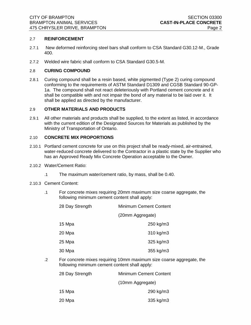
2.7 REINFORCEMENT
2.7.1 New deformed reinforcing steel bars shall conform to CSA Standard G30.12-M., Grade 400.
2.7.2 Welded wire fabric shall conform to CSA Standard G30.5-M.
2.8 CURING COMPOUND
2.8.1 Curing compound shall be a resin based, white pigmented (Type 2) curing compound conforming to the requirements of ASTM Standard D1309 and CGSB Standard 90-GP-1a. The compound shall not react deleteriously with Portland cement concrete and it shall be compatible with and not impair the bond of any material to be laid over it. It shall be applied as directed by the manufacturer.
2.9 OTHER MATERIALS AND PRODUCTS
2.9.1 All other materials and products shall be supplied, to the extent as listed, in accordance with the current edition of the Designated Sources for Materials as published by the Ministry of Transportation of Ontario.
2.10 CONCRETE MIX PROPORTIONS
2.10.1 Portland cement concrete for use on this project shall be ready-mixed, air-entrained, water-reduced concrete delivered to the Contractor in a plastic state by the Supplier who has an Approved Ready Mix Concrete Operation acceptable to the Owner.
2.10.2 Water/Cement Ratio:
.1 The maximum water/cement ratio, by mass, shall be 0.40.
2.10.3 Cement Content:
.1 For concrete mixes requiring 20mm maximum size coarse aggregate, the following minimum cement content shall apply:
28 Day Strength Minimum Cement Content
(20mm Aggregate)
15 Mpa 250 kg/m3
20 Mpa 310 kg/m3
25 Mpa 325 kg/m3
30 Mpa 355 kg/m3
.2 For concrete mixes requiring 10mm maximum size coarse aggregate, the following minimum cement content shall apply:
28 Day Strength Minimum Cement Content
(10mm Aggregate)
15 Mpa 290 kg/m3
20 Mpa 335 kg/m3
CITY OF BRAMPTON SECTION 03300 BRAMPTON ANIMAL SERVICES CAST-IN-PLACE CONCRETE 475 CHRYSLER DRIVE, BRAMPTON Page 3
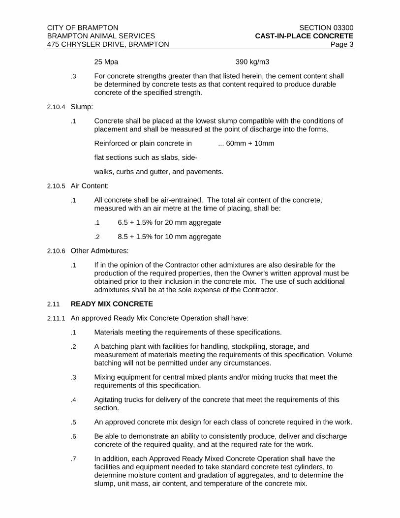
25 Mpa 390 kg/m3
.3 For concrete strengths greater than that listed herein, the cement content shall be determined by concrete tests as that content required to produce durable concrete of the specified strength.
2.10.4 Slump:
.1 Concrete shall be placed at the lowest slump compatible with the conditions of placement and shall be measured at the point of discharge into the forms.
Reinforced or plain concrete in ... 60mm + 10mm
flat sections such as slabs, side-
walks, curbs and gutter, and pavements.
2.10.5 Air Content:
.1 All concrete shall be air-entrained. The total air content of the concrete, measured with an air metre at the time of placing, shall be:
.1 6.5 + 1.5% for 20 mm aggregate
.2 8.5 + 1.5% for 10 mm aggregate
2.10.6 Other Admixtures:
.1 If in the opinion of the Contractor other admixtures are also desirable for the production of the required properties, then the Owner's written approval must be obtained prior to their inclusion in the concrete mix. The use of such additional admixtures shall be at the sole expense of the Contractor.
2.11 READY MIX CONCRETE
2.11.1 An approved Ready Mix Concrete Operation shall have:
.1 Materials meeting the requirements of these specifications.
.2 A batching plant with facilities for handling, stockpiling, storage, and measurement of materials meeting the requirements of this specification. Volume batching will not be permitted under any circumstances.
.3 Mixing equipment for central mixed plants and/or mixing trucks that meet the requirements of this specification.
.4 Agitating trucks for delivery of the concrete that meet the requirements of this section.
.5 An approved concrete mix design for each class of concrete required in the work.
.6 Be able to demonstrate an ability to consistently produce, deliver and discharge concrete of the required quality, and at the required rate for the work.
.7 In addition, each Approved Ready Mixed Concrete Operation shall have the facilities and equipment needed to take standard concrete test cylinders, to determine moisture content and gradation of aggregates, and to determine the slump, unit mass, air content, and temperature of the concrete mix.
CITY OF BRAMPTON SECTION 03300 BRAMPTON ANIMAL SERVICES CAST-IN-PLACE CONCRETE 475 CHRYSLER DRIVE, BRAMPTON Page 4
.8 Each plant shall carry out and record sufficient quality control tests on the
concrete materials, the plastic concrete, and the hardened concrete so as to ensure that concrete of the specified quality is delivered to the work.
2.11.2 Delivery of Ready Mix Concrete
.1 After completion of mixing, concrete shall be transported to the site by means of agitating or mixing trucks. The equipment shall be operated at the speed of rotation designated by the Manufacturer of the truck as the agitating speed.
2.11.3 The concrete shall be delivered to the site, without segregation, in a thoroughly mixed and uniform mass.
2.11.4 When concrete is transported to the site by means of agitating or mixing equipment, discharge of the concrete shall be completed within 1.5 hours after introduction of the mixing water to the cement and aggregates.
.1 Where the temperature of the concrete exceeds 27ºC, the time shall not be greater than 1 hour.
2.11.5 Control of Slump and Air Content.
.1 When a truck mixer or agitator is used for mixing or delivery of the concrete, no water from the truck water system or elsewhere shall be added after the initial introduction of the mixing water to the batch except when, at the start of discharge, the measured slump of the concrete is less than that specified. In this case water may be added so as to obtain the specified slump. Water shall not be added to the batch at any later time.
.2 Air entraining admixture may be added to the mixed concrete prior to discharge to increase the measured air content to the specified amount. The use of detraining admixtures to lower the air content of concrete is prohibited.
.3 When additional water or air entraining admixture is added to the concrete, the batch shall be mixed for an additional 30 revolutions at the designated mixing speed, or more if necessary, so that the uniformity requirements of the concrete are achieved.
.4 Adjustments to the slump and air content of the concrete, by the addition of water and air entraining admixture, are the responsibility of, and shall be made by, the Contractor.
3.0 EXECUTION
3.1 FORMWORK AND REINFORCING
3.1.1 Install formwork plumb and suitably braced to prevent movement during placing of concrete. Seal all joints to prevent seepage.
3.1.2 Place reinforcing with correct spacing and coverage using plastic support chairs, and other necessary accessories. Steel support chairs are not permitted.
3.2 TEMPERATURE CONTROL
3.2.1 Temperatures referred to are ambient air temperatures in the shade.
.1 Extreme rapid or severe drying conditions are those conditions when the rate of
CITY OF BRAMPTON SECTION 03300 BRAMPTON ANIMAL SERVICES CAST-IN-PLACE CONCRETE 475 CHRYSLER DRIVE, BRAMPTON Page 5
evaporation of surface moisture from the concrete exceeds 0.7 kg/m2/hr.
.2 Insulation materials mean wood fibre, mineral wool, glass fibre, plastic foam or other suitable material, having a thermal conductivity (k) not exceeding 0.038W/M/1°C per 25 mm. of thickness.
.3 Cold weather means those conditions when the air temperature is at or below 5°C or when the air temperature is likely to fall below 5°C within 24 hours.
.4 Hot weather means those conditions when the air temperature is at or above 27°C or when the air temperature is likely to rise above 27°C within 24 hours.
3.2.2 Cold Weather Concreting:
.1 When cold weather concreting is carried out.
.1 Provide temporary plant and equipment for heating concrete materials and forms. Protect, insulate and maintain the proper temperature and humidity of the concrete during curing in compliance with CSA Standard CAN3-A23.1-M90.
.2 Equipment shall be available, installed and tested ready for use at least one week before it is proposed to produce heated concrete.
.3 Where the specified concrete temperature is achieved by pre-heating, the concrete materials before batching shall not exceed 65°C.
.4 Water over 40°C shall not be brought into direct contact with the cement.
.5 Frozen lumps of aggregate shall not be added to the concrete. The method of heating aggregate stockpiles shall be such as to produce uniform conditions without local hot spots.
.6 The concrete temperature at the time of placing shall be between 10°C and 30°C.
.7 Cold weather concreting shall be inclusive to the price tendered and no further or separate payment will be made.
3.2.3 Hot Weather Concreting:
.1 When hot weather concreting is carried out.
.1 The maximum concrete temperature at the time of placing shall be:
.1 30°C for high strength concrete
.2 35°C for other concrete.
.2 Where ice is added to achieve the above conditions it shall be completely melted by the time concrete mixing is completed.
.1 Protect and cure in accordance with Section 21 of CSA Standard CAN3-A23.1M.
.2 Hot weather concreting will be inclusive to the price tendered and no further or separate payment will be made.

CITY OF BRAMPTON SECTION 03300 BRAMPTON ANIMAL SERVICES CAST-IN-PLACE CONCRETE 475 CHRYSLER DRIVE, BRAMPTON Page 6
3.2.4 Concrete placed under normal temperature conditions shall be deposited within the
temperature range of 10°C and 30°C.
3.3 EXAMINATION
3.3.1 Examine surfaces, conditions, and preparations upon which work of this Section depends. Clean, adjust, and supply as required.
3.3.2 Do not place any concrete until Owner has inspected and reviewed formwork and reinforcing and given written permission to pour.
3.3.3 Commencement of work will denote acceptance of surfaces and conditions.
3.4 PLACING CONCRETE
3.4.1 Notify Owner before scheduled placing of concrete.
3.4.2 Concrete shall be homogeneous, uniformly workable readily placeable into corners and angles of form and around reinforcements without permitting materials to segregate or excessive free water to collect on the surface.
3.4.3 Methods of conveying and placing are to be such that concrete components do not segregate.
3.4.4 Deposit concrete as close as possible to its final position. Lateral movement of concrete shall be avoided.
.1 When concrete is to be dropped more than 1.5 metres in height, fully enclosed vertical drop chutes or "elephant trunks" shall be used.
3.4.5 Concrete placing shall proceed as a continuous operation until the full section planned for concreting has been completed.
3.4.6 Concrete shall be placed in approximately horizontal layers at a rate such that each successive lift can be vibrated into the previous lift. The total depth of plastic concrete shall not exceed the depth dictated by the design of the forms.
3.4.7 Compact concrete with general purpose vibrators so that concrete is evenly and adequately distributed around and between reinforcing and against formwork, without honeycombing. Vibrators shall not be used in a manner which will cause segregation of the plastic concrete mix. External vibrating of forms is not permitted.
3.5 CURING AND PROTECTION
3.5.1 Beginning immediately after placement, protect concrete from premature drying, sunshine, excessively hot or cold temperatures, and mechanical injury. Maintain at a relatively constant temperature for as long as is required for hydration of the cement and curing of the concrete. Keep moisture loss to a minimum.
3.5.2 Cure horizontal surfaces by covering with polyethylene sheets with edges taped for at least 4 days. Lap edges 100mm minimum. The use of curing compounds shall be permitted but only with the written approval of the Owner.
3.5.3 It is the Contractor's responsibility to take all additional and necessary procedures and precautions to ensure the proper curing of the concrete.
CITY OF BRAMPTON SECTION 03300 BRAMPTON ANIMAL SERVICES CAST-IN-PLACE CONCRETE 475 CHRYSLER DRIVE, BRAMPTON Page 7
3.6 TREATMENT OF FORMED SERVICES
3.6.1 No formwork shall be removed without the permission of the Owner.
3.6.2 Immediately after the removal of forms, all bolts, ties, nails, or other metal not specifically required for construction purposes, shall be removed or cut back to a minimum depth of 15mm from the concrete surface. Such areas shall have their edges as nearly perpendicular to the surface as possible and be sufficiently deep to hold a patching mortar.
3.6.3 All cut-out areas and cavities shall be saturated with water and repaired. Scrub the surfaces to be patched with neat cement paste and fill with a finishing cement mortar using the same sand and cement as that used in the concrete.
3.6.4 On exposed formed surfaces, blend with white cement to obtain finish colour to match surrounding concrete surfaces.
3.6.5 In areas of honeycomb and where the repair is approved by the Owner, the Contractor shall, at his expense, remove the defective areas and fill with polymer modified mortar placed in strict accordance with the Manufacturer's recommendations.
3.6.6 Additional finish requirements, where required by the Owner, shall be as specified on the drawings.
END OF SECTION 03300
CITY OF BRAMPTON SECTION 15010 BRAMPTON ANIMAL SERVICES BASIC MECHANICAL REQUIREMENTS 475 CHRYSLER DRIVE, BRAMPTON Page 1
PART 1 - GENERAL
1.1. GENERAL
1.1.1. This section shall apply to all other sections of contract documents
1.2. SCOPE OF WORK
1.2.1. This section is intended to provide basic identification of the work for the Contractor to determine upfront, the nature of the work involved in this Contract. In no way shall this article be interpreted as being a full representation of the work of this Contract.
1.2.2. It is intended that the Work supplied under these Contract Documents shall be complete and fully operational in every detail for the purpose required. Include materials not herein mentioned, but which may be found necessary to complete or perfect any portion of the Work in accordance with the Contract Documents.
1.2.3. Specifications and Contract Drawings are complementary and items mentioned or indicated on one, may not necessarily be mentioned or indicated on the others, but shall in all cases be included in the Contract.
1.2.4. The terms “review”, “acceptance”, “acceptable”, “satisfactory”, “selected”, “directed”, “required”, “submit”, or similar words or phrases which are used in standards or elsewhere in the Contract Documents, it shall be understood, that words “by (to) the Consultant” follow, unless context provides otherwise.
1.2.5. The terms “exposed” or “exposed to view” refers to surfaces that are within the line of vision of persons from any accessible viewpoint, both within and outside the building. Where any part of a surface is exposed to view, all other portions of that surface to be considered as exposed to view.
1.2.6. This Work includes but is not limited to removals and construction of mechanical systems and associated works as indicated in Contract Documents and as required.
1.2.7. It is the Contractor's sole responsibility to examine all of the Commercial Documents, Specifications and Drawings issued.
1.2.8. The work involves the following:
1.2.8.1. Mechanical systems for the subject building as indicated on the drawings and as required including but not limited to the following:
1. Demolition and removal of existing makeup air units, removal and capping of unused gas piping.
2. Provision of HVAC units and other air conditioning systems and provision of natural gas piping to the proposed HVAC units, provision of gas piping to the natural gas generator and provision of gas piping to the future dryers.
3. Modification of existing HVAC controls and the existing BAS as specified.

CITY OF BRAMPTON SECTION 15010 BRAMPTON ANIMAL SERVICES BASIC MECHANICAL REQUIREMENTS 475 CHRYSLER DRIVE, BRAMPTON Page 2
4. Provision of an engineered walk-in freezer complete with all hardware
and refrigeration components, controls, wiring and accessories.
5. All associated condensate drain piping and necessary pipe insulation for the same.
6. Demolition and removal of the existing incinerator and demolition of all associated piping, electrical wiring and any other accessories associated with existing incinerator. Disposal of all demolished equipment and accessories in accordance with current regulations including payment of all associated costs.
7. This Contract includes the following, without limitation:
8. Supply, install, test and commission all specified equipment and accessories as indicated in the Contract Documents, Drawings and Specifications.
9. Associated BAS & controls work (including all equipment, device programming, wiring, conduits, transformers, relays etc.)
10. Testing, adjusting, balancing, equipment start-up c/w reports and commissioning of the mechanical systems including additional commissioning of the installed systems for alternate seasons (i.e. summer season, shoulder season and winter season).
11. Contractor shall carefully examine all documents to ensure a complete understanding of all Tender requirements. All fixed equipment is included in the Contract unless otherwise noted.
12. Contractor is strongly advised to share the tender documents with all major subcontractors to ensure coordination items are completely understood.
13. Associated cutting, patching and painting.
1.3. SCHEDULING OF THE WORK
1.3.1. Co-ordinate all mechanical work with the work of other trades and with the Owner. Scheduling of all work shall be coordinated with the facilities group and all construction work shall be carefully planned around the facilities programmes and activities. Allow for after hours and weekends work. Disruption to existing operations and shutdowns if any, shall be minimized. Complete all work as required coinciding with the completion date established for the Project.
1.3.2. Provide a detailed hoisting plan for review and approval. Hoisting plan shall be submitted 2 weeks prior to installation of roof mounted equipment.
1.3.3. Provide a minimum of 2 weeks advance notice to the facility’s personnel prior to commencing any shut downs.
1.3.4. Provide a detailed project schedule and submit not more than one month following Contract issuance. Maintain an updated project schedule and resubmit on the last day of each month. The project schedule is to be in the form of a

CITY OF BRAMPTON SECTION 15010 BRAMPTON ANIMAL SERVICES BASIC MECHANICAL REQUIREMENTS 475 CHRYSLER DRIVE, BRAMPTON Page 3
horizontal bar chart.
1.4. CODES, REGULATIONS AND STANDARDS
1.4.1. Comply with Municipal or Provincial Codes, Rules and Regulations and/or authorities having jurisdiction, including TSSA.
1.4.2. Revisions issue: latest version as amended to date.
1.5. PERMITS, CERTIFICATES, EQUIPMENT REGISTRATION AND FEES
1.5.1. Make application and pay all required fees for permits, registration, inspections, etc. for all equipment and systems installed including those required by the City, TSSA, local utility companies and the Region of Peel.
1.5.2. Upon substantial completion of work, supply and turn over to the Consultant all required inspection certificates from governing authorities to certify that the work as installed conforms to the rules and regulations of the governing authorities.
1.5.3. Permits
1.5.3.1. Obtain permits required for the installation of mechanical trades work including but not limited to:
1. Mechanical inspection
2. Piping inspection
3. Electrical inspection
4. TSSA inspection
1.5.3.2. Arrange for inspections and tests and pay all fees and costs for the permits, inspections and tests. Obtain permits immediately after notification of award of Contract.
1.5.3.3. Obtain copies of Drawings from the Consultant for submission with application for permits.
1.5.4. Material approvals
1.5.4.1. Obtain special inspection and approvals by CSA and/or local authorities, for materials and equipment where required or as specified.
1.5.4.2. Obtain such approval for the particular installation with the co-operation of the material supplier.
1.6. WORKING DRAWINGS AND DOCUMENTS
1.6.1. Design Drawing Intent
1.6.1.1. The design Drawings are schematic in arrangement, and describe the general design intent but do not show the exact details for the installation. They are not fabrication or installation Drawings.
1.6.1.2. The overall scope of work is suitably outlined on the Drawings with regard to
CITY OF BRAMPTON SECTION 15010 BRAMPTON ANIMAL SERVICES BASIC MECHANICAL REQUIREMENTS 475 CHRYSLER DRIVE, BRAMPTON Page 4
sizes, locations, general arrangements and installation details, and has been generally coordinated for routing of services. The routing of ductwork, piping and equipment arrangement are shown more or less in diagrammatic form except where in certain cases the Drawings may include details giving the exact locations and arrangements required.
1.6.1.3. The location of equipment, and the associated arrangement of piping, ductwork, and other material describes the general requirements of the work. Final location is dependent on the actual equipment supplied. The Consultant reserves the right to make reasonable adjustment of up to 1 m to the location of equipment, floor drains, routing of major piping and ductwork, at no additional cost to the Owner.
1.6.1.4. In order to provide clarity to the arrangement of the work, not all details including valves, thermometers, pressure gauges, etc. are shown on the plan Drawings. Refer to schematic Drawings, standard details and the specification for these requirements. In the absence of specific details, the Contractor is expected to follow generally accepted good installation practices.
1.6.1.5. Where specific installation dimensions for location of equipment and access space requirements are indicated on the Drawings, install to these requirements.
1.6.1.6. Where Standard Details are provided, these show the general installation requirements, and are applicable to each occurrence in the work, unless otherwise specified or shown.
1.6.1.7. Do not proceed with work where an obvious ambiguity is noted between tender documents and existing site conditions. Notify the Owner and obtain proper direction prior to proceeding with procurement or related construction work on site.
1.6.1.8. Where there is a contradiction with two selected products, materials, means, or methods, the Contractor shall issue a Request for Information (RFI) to the Consultant for clarification, in such circumstances, the Consultant shall be able to select the best option without additional expenses to the Owner.
1.6.2. Review before proceeding (HOLD)
1.6.2.1. Where the word "HOLD” appears on Drawings and other Contract Documents, the work is included in the Contract.
1.6.2.2. Execute such work only after verification of dimensions, verification of materials and obtaining Consultant's written permission to proceed.
1.6.3. Coordination and Cooperation with Other Trades
1.6.3.1. Review design drawings of all other related disciplines including architectural, electrical, structural and site services. Coordinate scope of work between all trades and allow for adequate costs for all related work. Coordinate work with all trades to ensure a proper and complete installation of fully functioning system that can be properly maintained in future.
1.6.3.2. Notify all trades concerned of the requirements for openings, sleeves, insets and
CITY OF BRAMPTON SECTION 15010 BRAMPTON ANIMAL SERVICES BASIC MECHANICAL REQUIREMENTS 475 CHRYSLER DRIVE, BRAMPTON Page 5
other hardware necessary for the installation and, where work is to be integrated with the work of other trades or is to be installed in close proximity with the work of the trades, carefully coordinate the work prior to installation.
1.7. EXISTING SITE CONDITIONS
1.7.1. The Contractor and sub trade to accept sole responsibility for any error or neglect on their part in ascertaining the nature of all existing conditions which will affect the Work of this section. No allowances will be made for any difficulties encountered by the Contractor and subtrades due to any features or peculiarities of the site surrounding property, or building, which exist at the time of tender submission.
1.7.2. Report any inconsistencies, ambiguities, discrepancies, omissions, and errors between site conditions and the Contract Documents to the Consultant prior to the commencement of the Work. If inconsistencies, ambiguities, discrepancies, omissions, and errors are not reported and clarified, the most stringent requirement shall govern, as determined by the Consultant.
1.7.3. Before commencing the Work of any section or trade, carefully examine the Work of other sections and trades upon which it may depend, examine substrate surfaces, and report in writing to the Consultant, defects which might affect new work. Commencement of the Work shall constitute acceptance of conditions and the work of other sections, trades, and other subcontractors upon which the new work depends. If repair of surfaces is required after commencement of specific work it shall be included in the Work of the trade providing the specific system or finish.
1.8. USE OF SITE
1.8.1. Accept full responsibility for assigned work areas from the time of the Contract award until Contract Completion.
1.8.2. Check means of access and egress, rights and interests which may be interfered with. Do not block lanes, roadways, entrances or exits. Direct construction traffic and locate access to site as directed by authorities having jurisdiction.
1.8.2.1. Animals present on site. Do not open any cages or allow animals to escape the facility and to the public.
1.8.3. Obtain and pay for use of additional storage or work areas needed for operations under this Contract.
1.8.4. Remove or alter existing work to prevent injury or damage to portions of existing work which remains.
1.8.5. Repair or replace portions of existing work which have been altered during construction operations to match existing or adjoining work, to the satisfaction of the Consultant.
1.8.6. At completion of operation condition of existing work, equal to or better than that existed before new work started. Make good all damage resulting from the Work.
CITY OF BRAMPTON SECTION 15010 BRAMPTON ANIMAL SERVICES BASIC MECHANICAL REQUIREMENTS 475 CHRYSLER DRIVE, BRAMPTON Page 6
1.9. COORDINATION AND EXAMINATION
1.9.1. Examination
1.9.1.1. Carefully examine work and Drawings of all related trades and thoroughly plan the work in advance so as to avoid interferences.
1.9.1.2. Report defects which would adversely affect the work. Do not commence installation until such defects have been corrected.
1.9.2. Coordination
1.9.2.1. Coordinate all work such that items will properly interface with work of other Divisions. Prepare installation and interference Drawings of all critical locations and submit to the Consultant for review.
1.9.2.2. Architectural Drawings, or in their absence, Mechanical Drawings govern all locations.
1.10. SUBMITTALS
1.10.1. Shop Drawings
1.10.1.1. Shop drawing shall be submitted electronically.
1.10.1.2. If the bidders wish to propose alternate products (for equipment and material other than specified equipment or system), a written RFI (Request For information) shall be submitted by the bidders before the close of question period during the tender process. Acceptance of alternates will be at the discretion of the Owner and Consultant. A response to the RFI will be issued in an Addendum confirming whether or not the alternate system is acceptable. Alternate systems will not be reviewed or accepted after close of tender.
1.10.1.3. Conform to general conditions of contract and the following:
1.10.1.4. Shop Drawings showing more than one size or model will not be considered unless properly marked up.
1.10.1.5. For electrically driven, and fuel fired appliances, provide the following information:
1. Electrical characteristics including voltage, phase, frequency and power rating.
2. For motors, NEMA, Class and efficiency ratings
3. Fuel input ratings, including flow rates and pressures
4. Equipment performance ratings, including flow rates, pressures, efficiencies, part load values and/or efficiencies (IPLV’s), plotted flow characteristics (pump and fan curves) with operating points clearly plotted.
1.10.1.6. For other equipment include the following information:
1. Equipment performance ratings, including flow rates, pressures drops.
CITY OF BRAMPTON SECTION 15010 BRAMPTON ANIMAL SERVICES BASIC MECHANICAL REQUIREMENTS 475 CHRYSLER DRIVE, BRAMPTON Page 7
2. Electrical control power requirements
1.10.1.7. For all equipment, include the following:
1. Equipment dimensions and weights.
2. Itemized product description with optional items clearly marked as being included.
1.10.1.8. Provide wiring Shop Drawings:
1. Wiring diagrams and schematics for all equipment which has electrical controls or devices furnished with the equipment.
2. Wiring diagrams alone are not sufficient; schematic and interconnecting Detailed Drawings and sequence of operation of all equipment are required for review.
3. Clearly indicate the materials and/or equipment being supplied:
1. Details of construction, finish, accurate dimensions, capacities and performance.
2. Certify Drawings correct for construction by the manufacturer, before submission.
3. Identify Equipment Shop Drawings with designations as shown on the Drawings or in the Specifications.
4. If not complied with, Shop Drawings will not be reviewed and will be returned to the Contractor.
4. Coordinate equipment which attaches to and/or where external wiring provided connects to other equipment.
1. Do such coordination whether such equipment is supplied under this or other contracts or subcontracts, for which relevant information will be provided by Owner/Consultant.
1.11. “AS-BUILT" RECORD DRAWINGS
1.11.1. Maintain an accurate dimensional record of all work completed on site including equipment, piping, ductwork, etc. All deviations and changes in equipment, piping, ductwork and accessories shall be recorded on the set of as-built drawings.
1.11.2. Upon completion of the project, provide electronic copy of the As-built drawings in AutoCAD format, as well as a PDF of each drawing to be accurately named and numbered. Include hard copies of the as-built Drawings in each of the O&M manuals.
1.12. INSTALLATION AND START-UP INSTRUCTIONS
1.12.1. Reference
1.12.1.1. Submit copies of installation instructions and copies of start-up instructions for any item of equipment when requested by the Consultant.

CITY OF BRAMPTON SECTION 15010 BRAMPTON ANIMAL SERVICES BASIC MECHANICAL REQUIREMENTS 475 CHRYSLER DRIVE, BRAMPTON Page 8
1.13. OPERATING AND MAINTENANCE INSTRUCTION MANUALS
1.13.1. Upon achieving Substantial Completion, submit within one month, two sets of binders to include operating and maintenance instruction manuals, as well as all warranties. Provide a CD containing all in PDF format.
1.13.1.1. Conform to project specifications.
1.13.1.2. In addition, include the following in the manuals:
1. Non-dimensional layout showing location of all electrical devices on mechanical equipment.
2. Operating instructions, including start-up and shut-down procedure.
3. Lubricating instructions and recommended cycle of lubrication for each item of equipment, including various types of lubricants.
4. List of spare parts.
1.13.1.3. All the above applies to component parts of equipment whether they are manufactured by the supplier of the equipment or are supplied as a component part of an item of equipment.
1.14. CLEANING, TESTING AND APPROVAL RECORDS
1.14.1. Records
1.14.1.1. Maintain records of all pressure tests and flushing and sterilization tests, glycol/water concentrations, inspections and approvals by the Plumbing Inspector.
1.14.1.2. Forward these tests to the Owner on completion of the work.
1.14.1.3. Forward to the Consultant, copy of records on site on completion of each test, cleaning operation, etc.
1.15. DIMENSIONS AND QUANTITIES
1.15.1. Dimensions
1.15.1.1. Dimensions shown on Drawings are approximate.
1.15.1.2. Verify dimensions by reference to Shop Drawings and field measurement.
1.15.2. Quantities
1.15.2.1. Quantities or lengths indicated in any of the Contract Documents are approximate only and shall not be held to gauge or limit the work.
1.16. PROJECT MANAGER
1.16.1. Provide a capable Project Manager to oversee and coordinate all administrative aspects of the Project.
1.16.2. The Project Manager is required to participate in construction kick-off meeting upon Contract issuance.
CITY OF BRAMPTON SECTION 15010 BRAMPTON ANIMAL SERVICES BASIC MECHANICAL REQUIREMENTS 475 CHRYSLER DRIVE, BRAMPTON Page 9
1.16.3. The Project Manager is responsible for conducting bi-weekly construction
meetings throughout the construction, as well as maintain meeting minutes and agendas for each meeting, all meeting minutes are to be issued within 5 business days of the meeting date.
1.16.4. The Project Manager is responsible for maintaining up to date and accurate logs for all project documents, included but not limited to Shop drawings, Change Orders, Change Directives, Contemplated Changes, Site Instructions, Requests for Information, and Cash Allowance Items.
1.17. WARRANTY
1.17.1. Unless otherwise noted elsewhere, all installed systems shall be provided with full parts and labour warranty for a period of 1 year from the date of substantial completion. For specific warranty details, refer to individual specification sections.
1.18.
PART 2 - PRODUCTS
2.1. MATERIALS AND EQUIPMENT
2.1.1. Materials
2.1.1.1. Use new materials and equipment, free from defects impairing strength and durability, as specified or specified equivalent.
2.1.1.2. Labelled or listed as required Code and/or inspection authorities.
2.1.1.3. Design of mechanical systems has been based on the first listed supplier and model number/size stated on the Equipment Schedules on the Drawings. Bear all costs due to physical or performance differences between stated equipment and proposed equipment. These differences include but are not limited to size, layout, arrangement, connection size, location and/or quantity of connections, or performance differences such as noise, power requirements, flow, throw, etc.
2.1.2. Equipment/Structure Coordination
2.1.2.1. Locations and dimensions of curbs and roof and floor opening framing, where indicated on the Drawings, are based on an arrangement to suit the above named supplier.
2.1.2.2. Be responsible to verify the actual size requirements of the openings, and notify the Consultant immediately in case the dimension of the unit supplied and the connecting ductwork/piping, etc. are at variance with the dimensions given on the Drawings.
2.1.2.3. Bear all costs for modification of curbs and floor/roof openings resulting from failure to notify the Consultant prior to the fabrication or construction of opening framing and curb.
2.2. STANDARD SPECIFICATIONS
2.2.1. Product Quality

CITY OF BRAMPTON SECTION 15010 BRAMPTON ANIMAL SERVICES BASIC MECHANICAL REQUIREMENTS 475 CHRYSLER DRIVE, BRAMPTON Page 10
2.2.1.1. Ensure that the chemical and physical properties, design, performance
characteristics and methods of construction of all Products provided comply with the latest issue of applicable Standard Specifications issued by Authorities having jurisdiction.
2.2.1.2. Do not apply such Standard Specifications to decrease the quality of workmanship, products and services required by the Contract Documents.
2.3. MANUFACTURER’S NAMEPLATES
2.3.1. Metal Nameplates
2.3.1.1. Provided with raised or recessed lettering, on each piece of equipment.
2.3.1.2. Mechanically fasten nameplate on a metal stand-off bracket arranged to clear insulation.
2.3.1.3. Mount on same stand-off Underwriters Laboratories and/or CSA registration plates.
2.3.2. Nameplate Data
2.3.2.1. Indicate:
1. Size
2. Capacity
3. Equipment model
4. Manufacturer’s name
5. Serial number
6. Voltage
7. Frequency
8. Phases
2.3.3. All nameplate data shall also be submitted electronically as part of the record submittals.
PART 3 - EXECUTION
3.1. GENERAL
3.1.1. Execute work in accordance with requirements specified in the various Sections of Division 15.
3.1.2. Coordinate all installation details and service requirements of equipment and accessories with other trades to eliminate conflicts prior to installation.
3.1.3. Mechanical equipment and accessories shall be installed in a manner that provides adequate access to equipment and also assists in reducing the effort for maintenance. Equipment shall only be installed at heights or in spaces that can be easily reached by a standard height ladder (i.e. not exceeding 3 metres). In case space constraints on site require installation of equipment in other locations

CITY OF BRAMPTON SECTION 15010 BRAMPTON ANIMAL SERVICES BASIC MECHANICAL REQUIREMENTS 475 CHRYSLER DRIVE, BRAMPTON Page 11
or heights, contractor shall bring this to the Owner’s attention and direction, prior to commencing work.
3.1.4. Lay out work of each trade so that it does not interfere with work under other Divisions of Specifications.
3.1.5. Make good any damage to Owner’s property or other trade’s work caused by improperly locating or carrying out of work.
3.1.6. Supply anchor bolts and templates for installation by other Divisions.
3.1.7. Location of pipes, ductwork, raceways and equipment may be altered without extra cost provided alteration is made before installation.
3.2. SPARE PARTS
3.2.1. Furnish spare parts
3.2.1.1. One casing joint gasket for each size pump.
3.2.1.2. One head gasket for each heat exchanger
3.2.1.3. One glass for each gauge glass
3.2.1.4. One set of V-belts for each drive
3.2.1.5. One filter cartridge or set of filter media for each filter or filter bank installed.
3.2.1.6. One set of strainer mesh for each type and each size of strainer to be installed after cleaning of piping systems.
3.2.1.7. 6 sets of sprinklers of each type as required by NFPA13.
3.2.1.8. Two complete sets of the filters for each MAU.
3.3. PROTECTION
3.3.1. Protect work and materials before, during and after erection from weather and other hazards and keep in a clean and orderly manner.
3.3.2. Protect pipe ends, valves and parts of equipment left unconnected to prevent damage or intrusion of foreign matter. Provide pipe caps for threaded male connections and plugs for threaded female connections.
3.3.3. Protect plumbing fixtures or mechanical equipment having a baked enamel finish by covering with polyethylene sheet securely held in place.
3.3.4. Protect the building envelope and finished floor slabs from scuffing, cracking, chipping, staining, cutting and other damage resulting from work of this Contract.
3.3.4.1. Place 19 mm thick plywood under laid with 25 mm thick polystyrene insulation board adhered to same, over floor areas when working from, or over, such surfaces. Provide such protection below hoist rigs, ladders, pallets of material, and in other circumstances where the flooring is exposed to potential damage. Work damaged due to failure in providing such protection is to be removed and
CITY OF BRAMPTON SECTION 15010 BRAMPTON ANIMAL SERVICES BASIC MECHANICAL REQUIREMENTS 475 CHRYSLER DRIVE, BRAMPTON Page 12
replaced, or repaired, as directed by the Owner, at no increase in Contract Price.
3.4. PAINTING
3.4.1. All paint is to match adjacent colours, the Contractor is responsible for providing colours for Consultant approval prior to painting.
3.4.2. With the exception of prime painting of miscellaneous steel or any other specific requirements as specified under the respective Sections of Division 15, all equipment shall be factory painted.
3.4.2.1. Factory applied finish painting:
1. Factory prime and final coats applied to pumps, air moving units, un-insulated pressure vessels, unit heaters, convectors, grilles, diffusers and bare metal equipment items, in exposed to view applications such as boiler rooms, mechanical rooms and fan rooms.
2. Use heat resistant paint where conditions require (i.e. equipment/accessories installed in the vicinity of heaters or boilers). Protect factory finished equipment during construction, and clean at completion of work.
3.4.2.2. Factory applied prime painting:
1. Factory prime paint other equipment fabricated from iron or steel including access doors, dampers, metal radiation enclosures, and fire hose cabinets.
2. In occupied areas of the building, touch up any damage to prime coat resulting from shipping or installation and leave ready for final painting under Division 9.
3.4.2.3. Field painting:
1. Mechanical rooms, boiler rooms, fan rooms, crawl spaces, pipe tunnels and penthouses: paint exposed galvanized metal surfaces with one coat of zinc dust galvanized primer and one coat of 100% alkyd base enamel.
2. Clean rust and oil from exposed iron and steel work provided under this Division, whether or not it has been factory prime painted. Paint this equipment with one coat of chrome oxide phenolic base primer and one coat of 100% alkyd base enamel in an approved colour.
3.5. SITE SAFETY
3.5.1. Provide hoarding and barriers as required to maintain a secure construction area in compliance with Ministry of Labour standards and the standards of any other authority having jurisdiction. Remove all hoarding and barriers at project completion and make good any resulting damage.
3.5.2. Provide traffic control persons for direction of pedestrian and vehicular traffic on site as required to perform the work.
3.5.3. Provide dust tight screens to localize dust, smoke, or debris generating activities.

CITY OF BRAMPTON SECTION 15010 BRAMPTON ANIMAL SERVICES BASIC MECHANICAL REQUIREMENTS 475 CHRYSLER DRIVE, BRAMPTON Page 13
3.5.4. Post signs labelled "DANGER DUE TO CONSTRUCTION - AUTHORIZED
PERSONNEL ONLY" at each entrance to the construction area. Provide all other way finding signage as required for the construction area.
3.5.5. The Contractor shall submit the following to the Consultant within 1 month of Contract issuance:
3.5.5.1. The Contractor's site-specific safety plan and associated procedures.
3.5.5.2. The Contractor's occupational health and safety policy and procedures.
3.5.5.3. The site-specific emergency response plan.
3.5.6. Conform to safe Work practices in accordance with regulations and authorities having jurisdiction.
3.5.7. Promptly report to Owner all accidents or if any claim is made by anyone against the Contractor or Subcontractor on account of any accident.
3.5.8. Provide at the Site, equipment to supply first aid service.
3.5.9. Fully indemnify the Owner and Consultant for any charges or convictions as a result of Work performed under this Contract.
3.5.10. Ensure that all personnel are adequately equipped to comply with safety regulations and that adequate safety equipment is available.
3.5.11. Maintain a copy on Site of the latest edition of the Occupational Health and Safety Act, for Construction Projects as well as Industrial Establishments.
3.6. PERFORMANCE OF WORK
3.6.1. All work shall be performed during normal business hours on Monday-Friday, between 7am to 5pm. The Owner requires that any disruptive work that produces excessive noise, heat and/or dust shall be carried out after normal business hours or on weekends.
END OF SECTION

CITY OF BRAMPTON SECTION 15050 BRAMPTON ANIMAL SERVICES BASIC MECHANICAL MATERIALS AND METHODS 475 CHRYSLER DRIVE, BRAMPTON Page 1
PART 1 - GENERAL
1.1. RELATED WORK
1.1.1. Other Divisions
1.1.1.1. Refer to other divisions of the Specifications and to the Drawings for work related to the mechanical work to avoid interferences with work of other trades (and other contractors) and to ensure proper completion of the work as a whole.
1.2. GENERAL CONSTRUCTION REQUIREMENTS
1.2.1. Applicable Codes and Standards
1.2.1.1. Ontario Building Code-2012
1.2.1.2. Occupational Health and Safety Act and Regulations for Construction Projects, Ontario Regulation 691.
1.2.1.3. Owners Health and Safety Requirements
1.2.2. Measurements and Deviations
1.2.2.1. Where any parts of the mechanical work are specifically located by dimensions on the Drawings, check and verify these dimensions on site prior to installation.
1.2.2.2. Before installing piping, review architectural, structural and electrical Drawings with mechanical Drawings
1. Where interference may occur and departures from arrangements as shown are required, consult with other trades involved, come to agreement as to changed locations or elevations and obtain approval of the Consultant for proposed changes before proceeding with the work.
1.2.2.3. Examine work of other trades or contractors, prior to commencement of mechanical installations.
1. Report in writing, to the Consultant, any discrepancies which will affect mechanical installations.
2. Failure to do so shall be considered acceptance of the conditions.
1.2.2.4. Where site conditions require minor deviations from indicated arrangements or locations, make such changes on approval of the Consultant without additional cost to the Owner.
1.2.2.5. Should any discrepancies occur during installation of mechanical work which will necessitate major revisions to the mechanical trades work or the work of other trades or contractors, notify the Consultant immediately and obtain written authorization before proceeding with the work.
1.2.3. Building Attachments:
1.2.3.1. Obtain prior written Consultant’s approval before drilling, cutting or welding of the building steel or building structure for erection of materials or equipment.

CITY OF BRAMPTON SECTION 15050 BRAMPTON ANIMAL SERVICES BASIC MECHANICAL MATERIALS AND METHODS 475 CHRYSLER DRIVE, BRAMPTON Page 2
1.2.4. Overloading
1.2.4.1. During installation of mechanical work, do not load any part of the building structure with a load greater than it is capable of bearing.
1. Should any accident occur or damage result through the violation of this requirement, the contractor shall be held solely responsible.
1.2.4.2. Design temporary supports used during installation as being equivalent to permanent supports.
1.2.4.3. Remove temporary supports at completion of work.
1.2.5. Cutting and Patching
1.2.5.1. Do not cut, remove or burn structural parts or sections of the building, whether they are steel, concrete or masonry without the written authorization of the Consultant.
1.2.5.2. Should cutting, repairing, and patching of previously finished work of other trades be required to allow installation of mechanical work, pay all costs for the trade concerned to perform the work.
PART 2 - PRODUCTS
2.1. BUILDING ATTACHMENTS
2.1.1. Welding Studs
2.1.1.1. Maximum size: 10 mm (3/8”) for attaching miscellaneous materials and equipment to building steel.
2.1.1.2. If the weight of materials or equipment require bolts or studs larger than 10mm (3/8”) diameter, use steel clips or brackets, secured to building steel by (welding or) bolting as approved by the Consultant.
2.1.1.3. Acceptable Manufacturers:
1. Graham
2. Omark
3. Nelson
4. Or approved equivalent
2.1.2. Self drilling expansion type concrete inserts:
2.1.2.1. To secure miscellaneous equipment and materials to masonry or concrete construction already in place.
2.1.2.2. Of sufficient number and size to prevent concrete from breaking away.
2.1.2.3. The use of powder or power actuated fasteners will not be allowed unless prior written approval is obtained from the Consultant.
2.1.2.4. Acceptable Manufacturers:

CITY OF BRAMPTON SECTION 15050 BRAMPTON ANIMAL SERVICES BASIC MECHANICAL MATERIALS AND METHODS 475 CHRYSLER DRIVE, BRAMPTON Page 3
1. ITW "Redhead"
2. Star "SSS"
3. USM "Parabolt"
4. Or approved equivalent
2.1.3. Supports for any suspended items:
2.1.3.1. Do not fasten/attach to or extend through steel pan type roofs or through concrete slab roofs.
2.1.4. Beam clamps:
2.1.4.1. 2-bolt design and of such type that the rod load is transmitted only concentrically to the beam web centreline.
2.1.4.2. The use of "C" and "I" beam side clamps, etc., will not be allowed without written consent of the Consultant.
2.1.4.3. Acceptable Manufacturers:
1. Grinnell
2. Myatt
3. Carpenter & Paterson
4. Or approved equivalent
2.1.5. Truss or steel joist roof or floor framing:
2.1.5.1. Locate hangers at or within 150mm (6”) of the joist top or bottom chord panel points
2.1.5.2. Otherwise provide additional structural steel as required where hanger spacing does not coincide with joist spacing.
2.1.5.3. Transmit hanger load only concentrically to the supporting truss or joist.
2.1.6. Secondary structural steel members between trusses and/or joists:
2.1.6.1. Locate at or within 150mm (6”) of top or bottom chord panel points.
2.1.6.2. Where the secondary structural steel member cannot be located at or near a truss or joist panel point, provide additional diagonal structural steel web member/members designed for the applicable load to the nearest panel point in the opposite chord member.
1. The above condition may be waived if the load to be suspended between panel points is not in excess of 45kg (100 LB).
2.1.6.3. Diagonal hangers which will induce lateral stresses in the chord members of the joist will not be permitted.
CITY OF BRAMPTON SECTION 15050 BRAMPTON ANIMAL SERVICES BASIC MECHANICAL MATERIALS AND METHODS 475 CHRYSLER DRIVE, BRAMPTON Page 4
2.2. DRIVES AND ACCESSORIES
2.2.1. Drives
2.2.1.1. V-belt drives selection: 150 percent of the motor size rating.
2.2.1.2. Sheaves: cast iron construction with machined grooves.
1. Sheaves 75mm (3”) size and larger diameter: taper lock bushings.
2. Multi-belt drives: matched sets.
3. Statically and dynamically balance all sheaves as an operating unit.
2.2.1.3. Adjustable sheaves:
1. Motors less than 1.1Kw (1.5 HP) rating: adjustable pitch motor sheave with diameter range selected to obtain specified RPM of the driven equipment at approximately the mid-point setting of the sheave.
2.2.1.4. Fixed Sheaves:
1. Motors of 1.1Kw (1.5 HP) and greater: solid type.
2. Should such sheaves not provide design requirements under operating conditions, supply and install a new drive sheave of proper size at no increase in Contract Price.
2.2.2. Drive Couplings
2.2.2.1. Acceptable Manufacturers:
1. Falk
2. Fast
3. Thomas
4. Or approved equivalent
2.2.3. Lubricating Devices
2.2.3.1. Equipment to have oil reservoirs with level indicators, or pressure grease fittings.
2.2.3.2. Inaccessible fittings: provide extended tubes to an accessible location.
2.2.3.3. Grease fittings: Zerk, Alemite or approved equivalent.
1. All fittings shall be of one type.
2.2.4. Drive Guards
2.2.4.1. To OSHA requirements.
2.2.4.2. Build guards of all welded construction on exposed rotating parts or elements and on all drives including the following:
1. V-belt drives
2. Flexible couplings
CITY OF BRAMPTON SECTION 15050 BRAMPTON ANIMAL SERVICES BASIC MECHANICAL MATERIALS AND METHODS 475 CHRYSLER DRIVE, BRAMPTON Page 5
3. Gear drives
2.2.4.3. Construction (except fan drives):
1. Total enclosure type fabricated of minimum 1.3mm (18 ga.) black sheet steel.
2. Hinged side to allow access for lubrication, inspection or removal of the drive parts.
3. Maximum clearance of openings in guards to rotating parts: not to exceed 13mm (1/2”).
4. Make provision for slide rail adjustment.
2.2.4.4. Construction for fan drives:
1. V-belt drives: total enclosure type as specified above.
2. Enclosure sides: 13mm (1/2”) mesh, 2.7mm (0.105”) wire screening.
3. Tachometer holes at shaft centres, reinforced as required to maintain rigidity of guard.
2.2.4.5. Flexible drive coupling guards:
1. Location: between motor and driven equipment
2. Minimum 1.3mm (18 ga.) black sheet steel, securely fastened to the equipment base plate and readily removable.
3. Leave a clearance of approx. 13mm to 25mm (1/2” to 1”) between the guard and the coupling.
4. Extend the guard to within 13mm (1/2”) of both motor and driven equipment housing.
2.2.4.6. Rework any substandard guards supplied with mechanical equipment to conform to the above requirements.
2.3. SEALANTS, CONCRETE AND GROUTS
2.3.1. Pipe Sleeve Seals
2.3.1.1. Acceptable Manufacturers:
1. Thunderline "Link-Seal" Series LS
2. Century-Line
3. Metraflex
4. Or approved equivalent
2.3.2. Concrete
2.3.2.1. Strength: Unless otherwise noted, 25 MPa concrete: to CSA-A23.1/A23.2
2.3.3. Concrete Grouts
CITY OF BRAMPTON SECTION 15050 BRAMPTON ANIMAL SERVICES BASIC MECHANICAL MATERIALS AND METHODS 475 CHRYSLER DRIVE, BRAMPTON Page 6
2.3.3.1. Acceptable Manufacturers:
1. Sternson "M-Bed Standard"
2. Sika "Sikagrout 212"
3. Master Builders "Construction Grout"
4. Meadows "CG-86"
5. Euclid "Euco NS Grout"
6. CPD "Non-Shrink Grout"
7. Or approved equivalent
2.3.4. Bonding Agents
2.3.4.1. Acceptable Manufacturers:
1. Sika "Sikadur 32" Hi-Mod
2. Or approved equivalent
2.3.5. Caulking Compounds
2.3.5.1. Acceptable Manufacturers:
1. Denso-Plast
2. Or approved equivalent
2.3.6. Firestopping
2.3.6.1. ULC listed fire stopping assembly
2.3.6.2. Rating to suit wall and floor penetrations
2.3.6.3. Acceptable Manufacturers:
1. Hilti
2. Fire Stop Systems
3. Dow Corning
4. 3M
5. Tremco
6. A/D Fire Protection System
7. Johns Manville
8. Or approved equivalent
2.4. MISCELLANEOUS
2.4.1. Access Doors
2.4.1.1. Size:
1. Minimum size: 300mm x 300mm (12” x 12”) size, unless otherwise

CITY OF BRAMPTON SECTION 15050 BRAMPTON ANIMAL SERVICES BASIC MECHANICAL MATERIALS AND METHODS 475 CHRYSLER DRIVE, BRAMPTON Page 7
specified on the Drawings or in other divisions of the Specifications, or as required to replace or repair said equipment.
2. Provide 600 x 600 size access doors where personnel entry is required.
3. Where access doors are required to be located in fire rated walls, floors and ceilings, provide ULC listed and labelled units having a minimum rating in hours per OBC for the structure being penetrated.
2.4.1.2. Material:
1. Fabricated of 2.5mm (12 ga) bonderized steel.
2. Fabricated of 2.5mm (12 ga) stainless steel in areas finished with tile or marble surfaces.
3. Flush mounted, concealed hinges and screwdriver lock.
4. Plast lock and anchor straps.
5. Doors to be of a type and fire rating to suit the particular type of wall or ceiling construction in which they are to be installed.
2.4.1.3. Acceptable Manufacturers:
1. E.H. Price
2. Titus
3. Controlled Air
4. Williams (S.M.S.)
5. Acudor
6. Or approved equivalent
2.4.2. Isolating Unions
2.4.2.1. Acceptable Manufacturers:
1. Epco
2. Marpac "Petro"
3. Corrosion Service
4. Or approved equivalent
2.4.3. Fabricated Equipment Supports (Floor Stands and Ceiling or Wall Mounted Supports)
2.4.3.1. Structural steel members of welded construction or steel pipe and fittings, suitably braced and secured to the floor by mild steel floor pads or pipe flanges with bolts or anchors.
PART 3 - EXECUTION
3.1. EQUIPMENT
3.1.1. General

CITY OF BRAMPTON SECTION 15050 BRAMPTON ANIMAL SERVICES BASIC MECHANICAL MATERIALS AND METHODS 475 CHRYSLER DRIVE, BRAMPTON Page 8
3.1.1.1. Install equipment in a compact, neat and workmanlike manner.
1. Align, level and adjust for satisfactory operation.
2. Install in such a manner that connecting and disconnecting of piping and accessories can be made readily and that all parts are easily accessible for inspection, operation, maintenance and repair.
3.1.1.2. Install and start up items of equipment in accordance with the manufacturer's printed installation and operating instructions.
3.1.2. Noise and Vibration
3.1.2.1. Noise and vibration levels of equipment and systems shall be within design intent.
3.1.2.2. If noise or vibration levels created by any mechanical equipment and systems and transmitted to occupied portions of building or other mechanical work are over the limits, make all necessary changes and additions as approved by the Consultant without additional cost.
3.1.3. Lubrication
3.1.3.1. Lubricate all equipment prior to start up in accordance with the manufacturer's printed instructions.
3.1.3.2. Supply all lubrication including sufficient quantity for drainage and refilling of oil sumps, etc., when required by manufacturer's instructions.
3.1.4. Equipment Bases and Pads
3.1.4.1. Construct bases and pads for all mechanical equipment. Pads shall be constructed of concrete c/w reinforcement and dowels. Refer to structural drawings and specifications for details.
3.1.4.2. Layout coordination:
1. Verify size of bases shown on Drawings with actual requirements and advise the Consultant and the respective trades if change in size or shape of pad is required.
3.1.4.3. Anchor bolts:
1. Supply anchor bolts required for mechanical equipment unless indicated otherwise on the Drawings.
2. Sleeve anchor bolts.
3. Supply anchor bolts and sleeves to trade constructing bases in sufficient time for setting in formwork prior to placing concrete and provide anchor bolt location drawing or template for locating anchor bolts.
1. Check anchor bolt locations for proper position before concrete is poured.
3.1.5. Setting and Alignment of Equipment
CITY OF BRAMPTON SECTION 15050 BRAMPTON ANIMAL SERVICES BASIC MECHANICAL MATERIALS AND METHODS 475 CHRYSLER DRIVE, BRAMPTON Page 9
3.1.5.1. Rotating equipment (fans, pumps, etc):
1. Use millwrights to set and align to lines established with an engineer's level.
2. Shim equipment using standard brass or bronze shim stock of suitable thickness to provide proper level and alignment.
3. Place 25mm (1”) minimum thick grout between equipment base and concrete pad or foundation.
4. Have the Consultant approve equipment settings for equipment mounted on concrete pads or foundations prior to grouting.
5. Re-check alignment prior to start-up of equipment.
3.1.6. Ceiling or Wall Mounting
3.1.6.1. Where ceiling or wall mounting is indicated or required, provide a suspended platform, bracket or shelf.
3.1.6.2. Materials: standard steel members and steel plates of welded construction throughout.
3.1.6.3. Attach to building steel with rod hangers and beam clamps, or attach to precast structure as the case may be.
3.1.6.4. Place additional structural steel as required between building steel where beam spacing does not meet requirements.
3.1.6.5. Do not use inserts unless specifically shown on the Drawings or approved by the Consultant for any particular item of equipment.
3.1.6.6. Attach brackets or shelves to vertical member or sections of the building structure as hereinbefore specified.
3.1.7. Suspended Equipment Support: Provide double locknuts on suspended equipment supports as follows:
3.1.7.1. Upper attachment
1. Beam clamp: provide a double nut on end of beam clamp tie rod.
2. Supplemental steel: double nut all mechanical fasteners fixing supplemental steel to building structural steel.
3.1.7.2. Middle attachment
1. Upper load bearing point, to beam clamp: not applicable.
2. Upper load bearing point, to supplemental steel: double nut on top of load bearing point, single locknut on underside of bearing point
3. Lower load bearing point, all: double nut on underside of bearing point, single locknut on top of bearing point.
3.1.7.3. Lower attachment
CITY OF BRAMPTON SECTION 15050 BRAMPTON ANIMAL SERVICES BASIC MECHANICAL MATERIALS AND METHODS 475 CHRYSLER DRIVE, BRAMPTON Page 10
1. Trapeze hanger or equipment fastening: refer to middle attachment
requirements above.
3.1.7.4. Apply Loctite 242 to the second nut (and matchmark both nuts).
3.2. MISCELLANEOUS STEEL
3.2.1. General
3.2.1.1. Hang or support equipment, piping, ductwork etc., with miscellaneous structural supports, platforms, braces as may be required unless Drawings or other Sections of the Specifications state otherwise.
3.2.2. Materials and Fabrication
3.2.2.1. Conform to:
1. CAN/CSA-S16.1-M Limit Status Design of Steel Structures.
2. CSA-G40.20/G40.21 grade 300W for General requirement for rolled or welded Structural Quality SteelCSA W47.1 - for qualification of welders.
3. CSA W48.1-M - for electrodes (only coated rods allowed).
4. CSA W59-M - Welded Steel Construction (Metal Arc Welding).
5. CSA W117.2 - for safety in welding.
3.2.2.2. Construction:
1. Welded construction wherever practicable.
2. Chip welds to remove slag, and grind smooth.
3. Bolted joints allowed for field assembly using high strength steel bolts.
3.2.3. Painting and Cleaning
3.2.3.1. Clean steel to Steel Structures Painting Council SSPC-SP6, Commercial Blast Cleaning.
3.2.3.2. Apply one coat of oil alkyd primer conforming to CISC/CPMA 2.75 to all miscellaneous steel.
3.2.3.3. In the field, touch up all bolt heads and nuts, previously unpainted connections and surfaces damaged during erection with primer as hereinbefore specified.
3.2.3.4. Apply two coats of primer to all surfaces which will be inaccessible after erection.
3.2.3.5. Thoroughly remove all foreign matter from steelwork on completion of installation.
3.3. CONCRETE INSERTS
3.3.1. General
3.3.1.1. Install inserts required for attachment of hangers, either for suspension of piping or equipment.
CITY OF BRAMPTON SECTION 15050 BRAMPTON ANIMAL SERVICES BASIC MECHANICAL MATERIALS AND METHODS 475 CHRYSLER DRIVE, BRAMPTON Page 11
3.3.1.2. For masonry or poured concrete construction use expansion type units. Insert
into the concrete after concrete has cured. Do not use anchors or inserts installed by explosive means.
3.4. FLASHINGS
3.4.1. Coordination
3.4.1.1. Coordinate with general trades and roofing supplier.
3.4.2. Provide flashing and counter-flashing for all mechanical and related electrical penetrations through roof. Costs resulting from failure to comply with this requirement are the sole responsibility of the contractor.
3.4.3. Acceptable Manufacturer: Thaler Metal
3.4.3.1. Plumbing Vent: Thaler model MEF-1
3.4.3.2. Flexible steel conduit: Thaler model MEF-2x
3.4.3.3. Hot pipe: MEF-3A with stainless steel collar
3.4.3.4. Type B vents: MEF-4A
3.4.3.5. Rigid conduit: MEF-AE1
3.4.3.6. Gas Piping: MEF-9
3.4.3.7. Or approved equivalent.
3.5. FIRE STOPPING
3.5.1. Submittals
3.5.1.1. Submit shop Drawings, including the following information:
1. ULC/CUL listing number
2. Installation Drawings for each type of penetration
3. Installation materials
3.5.2. General
3.5.2.1. Seal piping, ductwork, conduits and miscellaneous support steel penetrating fire separations.
3.5.2.2. Install fire stopping in accordance with manufacturer’s instructions and ULC listing requirements.
3.5.2.3. Provide a written report on completion of fire stopping, by area or floor if necessary, indicating the work is completed and ready for inspection. Do not cover over fire stopping, including installation of walls and ceilings, until work is inspected.

CITY OF BRAMPTON SECTION 15050 BRAMPTON ANIMAL SERVICES BASIC MECHANICAL MATERIALS AND METHODS 475 CHRYSLER DRIVE, BRAMPTON Page 12
3.6. ACCESS DOORS
3.6.1. General
3.6.1.1. Access doors in ductwork are specified in Section 15820 “Ductwork Accessories”.
3.6.1.2. Supply access doors for installation by other trades in walls or ceilings where accessibility is required for the operation and/or maintenance of:
1. Concealed valves
2. Traps
3. Cleanouts
4. Dampers
5. Fan Coil Units
6. Controls equipment
3.7. PERFORMANCE AND BALANCING
3.7.1. Refer to section 15990 Start-up and Performance Testing.
3.8. ADJUSTMENT AND OPERATION OF SYSTEMS
3.8.1. General
3.8.1.1. When the work is complete:
1. Adjust equipment items of the various systems for proper operation within the framework of design intent, and the operating characteristics as published by the equipment manufacturer.
2. Complete additional instructions are specified under the respective Sections of Division 15.
3.8.1.2. The Consultant reserves the right to require the services of an authorized representative of the manufacturer in the event that any item of equipment is not adjusted properly.
1. Arrange for such services and pay all costs thereof.
2. After completion of adjustments, place systems in full operating condition and advise the Consultant that the work is ready for acceptance.
3.9. ACCEPTANCE
3.9.1. General
3.9.1.1. After all equipment has been installed and adjusted and all systems balanced:
1. Conduct performance tests in the presence of the Consultant, Manufacturer and the Owner.
2. Arrange the time for these tests at the convenience of the Consultant and the Owner.
CITY OF BRAMPTON SECTION 15050 BRAMPTON ANIMAL SERVICES BASIC MECHANICAL MATERIALS AND METHODS 475 CHRYSLER DRIVE, BRAMPTON Page 13
3. Conduct tests under climatic circumstances to ensure complete and
comprehensive tests and of such a manner and duration as the Consultant may deem necessary.
3.9.1.2. During these tests:
1. Demonstrate the correct performance of all equipment items and of the systems they comprise.
2. Should any system or any equipment item fail to function as required, make such changes, adjustments or replacements necessary to meet performance requirements.
3. Repeat tests until requirements have been fully satisfied and all systems accepted by the Consultant.
3.10. COORDINATION WITH TESTING AND BALANCING WORK
3.10.1. General
3.10.1.1. Review with the mechanical contractor before fabrication:
1. Location of balancing devices
2. Test connections
3. Access openings
3.10.1.2. Report conditions which could affect optimum system performance.
3.10.1.3. Inspection:
1. Assure that all testing, balancing and metering devices are installed properly and in pre-selected locations.
2. Report any errors to the Consultant.
3. The mechanical contractor shall obtain the approval of the Testing and Balancing Firm before relocating these devices due to field conditions.
3.10.2. TAB Contractor Coordination
3.10.2.1. Cooperate with the mechanical contractor giving adequate prior notification of request for services of tradesmen.
3.10.2.2. Coordinate efforts so that items requiring replacement and/or delivery time (sheaves, motors, etc.) are tested as early as possible.
3.10.3. Mechanical contractor coordination
3.10.3.1. Cooperate with the Testing and Balancing Firm.
3.10.3.2. Provide the following assistance and/or services:
1. Schedule sufficient time so that the initial testing and balancing can be completed before occupancy begins and coordinate with the trades involved.
2. Keep the Testing and Balancing Company informed of any major
CITY OF BRAMPTON SECTION 15050 BRAMPTON ANIMAL SERVICES BASIC MECHANICAL MATERIALS AND METHODS 475 CHRYSLER DRIVE, BRAMPTON Page 14
changes made during construction and provide same with a set of project Drawings and reviewed Shop Drawings.
3. Provide balancing devices, test connections access openings, balancing probe inlets and plugs.
4. Clean and pre-run all equipment, filters, etc. and place all heating, ventilating and air conditioning systems into full operation and continue same during each working day of testing and balancing.
5. Provide immediate labour from pertinent mechanical trades and tools, equipment and materials to make equipment and system alterations and adjustments, as required including control adjustments.
6. Make available all equipment data (Shop Drawing performance data and operating instructions) to the Testing and Balancing Firm.
7. Notify the Testing and Balancing Firm to return on site to perform their services after the deficiencies have been corrected.
3.10.3.3. As part of the coordination effort, the mechanical contractor shall be fully responsible for systems constructed, installed and adjusted to provide optimum performance as required by design intent. Any re-adjusting required as the result of spot checks by the Consultant shall be done at no increase in Contract Price.
3.10.3.4. Nothing contained in this Section voids the responsibility of the Contractor for systems constructed, installed and adjusted to achieve the design intent.
END OF SECTION
CITY OF BRAMPTON SECTION 15060 BRAMPTON ANIMAL SERVICES PIPES HANGERS AND SUPPORTS 475 CHRYSLER DRIVE, BRAMPTON Page 1
PART 1 - GENERAL
1.1. SUBMITTALS
1.1.1. Shop Drawings
1.1.1.1. Submit Shop Drawings in accordance with 15010 “Basic Mechanical Requirements”.
1.1.1.2. Submit layout Drawings showing each type and placement of manufactured, pre-fabricated roof piping support system. Submit details for fixing roofing pad to roof.
PART 2 - PRODUCTS
2.1. MATERIALS
2.1.1. Acceptable Manufacturers
2.1.1.1. Hangers:
1. Anvil
2. Myatt
3. Carpenter & Paterson
4. Hunt
5. B-Line
6. Or approved equivalent
2.1.1.2. Insulation shields:
1. Anvil
2. Myatt
3. Pipe Shields Inc.
4. Or approved equivalent
2.1.2. Lower Attachment
2.1.2.1. Clevis hanger – steel pipe
1. Standard weight black steel clevis hangers with level adjustment and locknut
2. Anvil figures 260 and 300.
3. For figure 260, provide clevis bolt spacer on insulated piping.
4. Or approved equivalent
2.1.2.2. Clevis hanger – copper pipe
1. Light weight black steel clevis hangers with copper coloured finish and plastic insert to suit local authority requirements, with level adjustment and locknut.
CITY OF BRAMPTON SECTION 15060 BRAMPTON ANIMAL SERVICES PIPES HANGERS AND SUPPORTS 475 CHRYSLER DRIVE, BRAMPTON Page 2
2. Anvil figure CT-65.
3. Or approved equivalent
2.1.2.3. Roller hanger
1. Adjustable roller type hangers with locknuts.
2. Rollers of sufficient width to clear the outside diameter of the insulation on the piping.
3. Support rollers at both ends, either by a yoke, swivel type hanger or by two adjustable rods with locknuts (double locknuts).
4. Anvil figure 177 or 171 as applicable.
5. Or approved equivalent
2.1.3. Insulation Protection
2.1.3.1. Insulation saddles, for welding to pipe:
1. Anvil figure 160-165 as applicable.
2. Or approved equivalent
2.1.3.2. Insulation shields :
1. Either shop fabricated, or manufactured plates of the size required to properly fit the outside diameter of the pipe insulation.
2. Anvil figure167, modified with holes at each end to suit 12 mm wide. stainless steel band clamps.
3. Shop fabricate bearing plates conforming to the following table for various pipe sizes:
Pipe Size (NPS)
Length of Plate mm
Thickness of Plate mm
½ to 2 300 1.2
3 to 4 300 1.52
4. Form the bearing plates to the O.D. of the adjoining pipe insulation and extend the plate up to the horizontal centre line of the pipe.
2.1.4. Middle Attachment
2.1.4.1. Machine threaded rods
1. Black steel finish in concealed areas.
2. Galvanized finish in mechanical rooms and exposed areas.
2.1.5. Upper Attachments
2.1.5.1. Beam clamps:
1. Malleable iron C-Clamp with retaining clip, FM approved: Anvil figure 87,
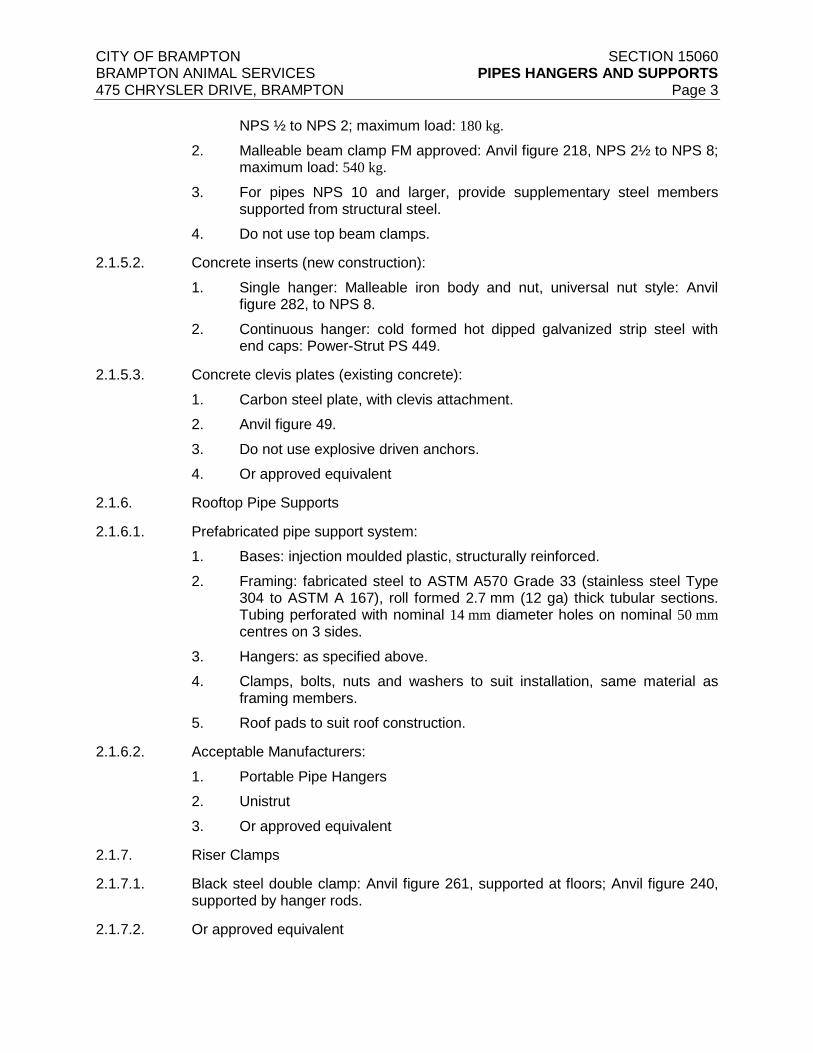
CITY OF BRAMPTON SECTION 15060 BRAMPTON ANIMAL SERVICES PIPES HANGERS AND SUPPORTS 475 CHRYSLER DRIVE, BRAMPTON Page 3
NPS ½ to NPS 2; maximum load: 180 kg.
2. Malleable beam clamp FM approved: Anvil figure 218, NPS 2½ to NPS 8; maximum load: 540 kg.
3. For pipes NPS 10 and larger, provide supplementary steel members supported from structural steel.
4. Do not use top beam clamps.
2.1.5.2. Concrete inserts (new construction):
1. Single hanger: Malleable iron body and nut, universal nut style: Anvil figure 282, to NPS 8.
2. Continuous hanger: cold formed hot dipped galvanized strip steel with end caps: Power-Strut PS 449.
2.1.5.3. Concrete clevis plates (existing concrete):
1. Carbon steel plate, with clevis attachment.
2. Anvil figure 49.
3. Do not use explosive driven anchors.
4. Or approved equivalent
2.1.6. Rooftop Pipe Supports
2.1.6.1. Prefabricated pipe support system:
1. Bases: injection moulded plastic, structurally reinforced.
2. Framing: fabricated steel to ASTM A570 Grade 33 (stainless steel Type 304 to ASTM A 167), roll formed 2.7 mm (12 ga) thick tubular sections. Tubing perforated with nominal 14 mm diameter holes on nominal 50 mm centres on 3 sides.
3. Hangers: as specified above.
4. Clamps, bolts, nuts and washers to suit installation, same material as framing members.
5. Roof pads to suit roof construction.
2.1.6.2. Acceptable Manufacturers:
1. Portable Pipe Hangers
2. Unistrut
3. Or approved equivalent
2.1.7. Riser Clamps
2.1.7.1. Black steel double clamp: Anvil figure 261, supported at floors; Anvil figure 240, supported by hanger rods.
2.1.7.2. Or approved equivalent
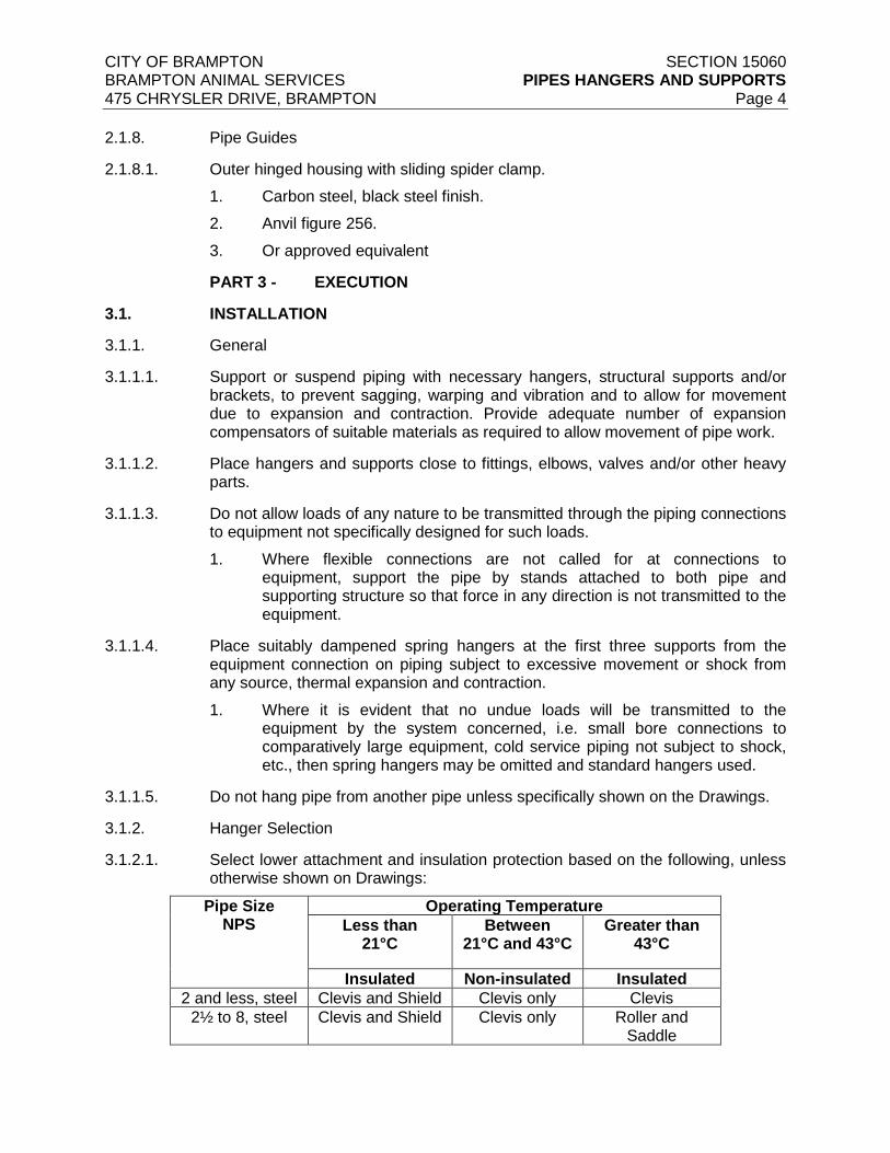
CITY OF BRAMPTON SECTION 15060 BRAMPTON ANIMAL SERVICES PIPES HANGERS AND SUPPORTS 475 CHRYSLER DRIVE, BRAMPTON Page 4
2.1.8. Pipe Guides
2.1.8.1. Outer hinged housing with sliding spider clamp.
1. Carbon steel, black steel finish.
2. Anvil figure 256.
3. Or approved equivalent
PART 3 - EXECUTION
3.1. INSTALLATION
3.1.1. General
3.1.1.1. Support or suspend piping with necessary hangers, structural supports and/or brackets, to prevent sagging, warping and vibration and to allow for movement due to expansion and contraction. Provide adequate number of expansion compensators of suitable materials as required to allow movement of pipe work.
3.1.1.2. Place hangers and supports close to fittings, elbows, valves and/or other heavy parts.
3.1.1.3. Do not allow loads of any nature to be transmitted through the piping connections to equipment not specifically designed for such loads.
1. Where flexible connections are not called for at connections to equipment, support the pipe by stands attached to both pipe and supporting structure so that force in any direction is not transmitted to the equipment.
3.1.1.4. Place suitably dampened spring hangers at the first three supports from the equipment connection on piping subject to excessive movement or shock from any source, thermal expansion and contraction.
1. Where it is evident that no undue loads will be transmitted to the equipment by the system concerned, i.e. small bore connections to comparatively large equipment, cold service piping not subject to shock, etc., then spring hangers may be omitted and standard hangers used.
3.1.1.5. Do not hang pipe from another pipe unless specifically shown on the Drawings.
3.1.2. Hanger Selection
3.1.2.1. Select lower attachment and insulation protection based on the following, unless otherwise shown on Drawings:
Pipe Size NPS
Operating Temperature
Less than 21°C
Between 21°C and 43°C
Greater than 43°C
Insulated Non-insulated Insulated
2 and less, steel Clevis and Shield Clevis only Clevis
2½ to 8, steel Clevis and Shield Clevis only Roller and Saddle
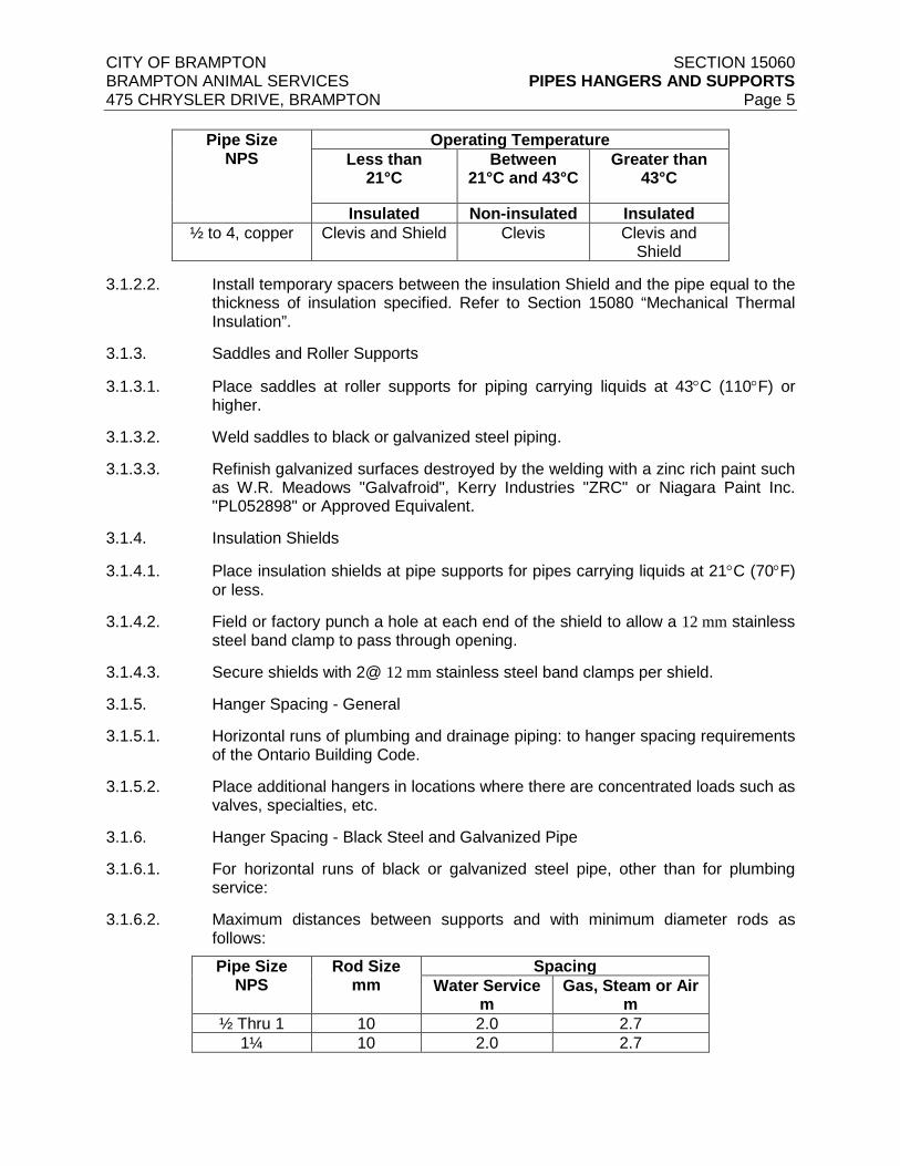
CITY OF BRAMPTON SECTION 15060 BRAMPTON ANIMAL SERVICES PIPES HANGERS AND SUPPORTS 475 CHRYSLER DRIVE, BRAMPTON Page 5
Pipe Size NPS
Operating Temperature
Less than 21°C
Between 21°C and 43°C
Greater than 43°C
Insulated Non-insulated Insulated
½ to 4, copper Clevis and Shield Clevis Clevis and Shield
3.1.2.2. Install temporary spacers between the insulation Shield and the pipe equal to the thickness of insulation specified. Refer to Section 15080 “Mechanical Thermal Insulation”.
3.1.3. Saddles and Roller Supports
3.1.3.1. Place saddles at roller supports for piping carrying liquids at 43°C (110°F) or higher.
3.1.3.2. Weld saddles to black or galvanized steel piping.
3.1.3.3. Refinish galvanized surfaces destroyed by the welding with a zinc rich paint such as W.R. Meadows "Galvafroid", Kerry Industries "ZRC" or Niagara Paint Inc. "PL052898" or Approved Equivalent.
3.1.4. Insulation Shields
3.1.4.1. Place insulation shields at pipe supports for pipes carrying liquids at 21°C (70°F) or less.
3.1.4.2. Field or factory punch a hole at each end of the shield to allow a 12 mm stainless steel band clamp to pass through opening.
3.1.4.3. Secure shields with 2@ 12 mm stainless steel band clamps per shield.
3.1.5. Hanger Spacing - General
3.1.5.1. Horizontal runs of plumbing and drainage piping: to hanger spacing requirements of the Ontario Building Code.
3.1.5.2. Place additional hangers in locations where there are concentrated loads such as valves, specialties, etc.
3.1.6. Hanger Spacing - Black Steel and Galvanized Pipe
3.1.6.1. For horizontal runs of black or galvanized steel pipe, other than for plumbing service:
3.1.6.2. Maximum distances between supports and with minimum diameter rods as follows:
Pipe Size NPS
Rod Size mm
Spacing
Water Service m
Gas, Steam or Air m
½ Thru 1 10 2.0 2.7
1¼ 10 2.0 2.7
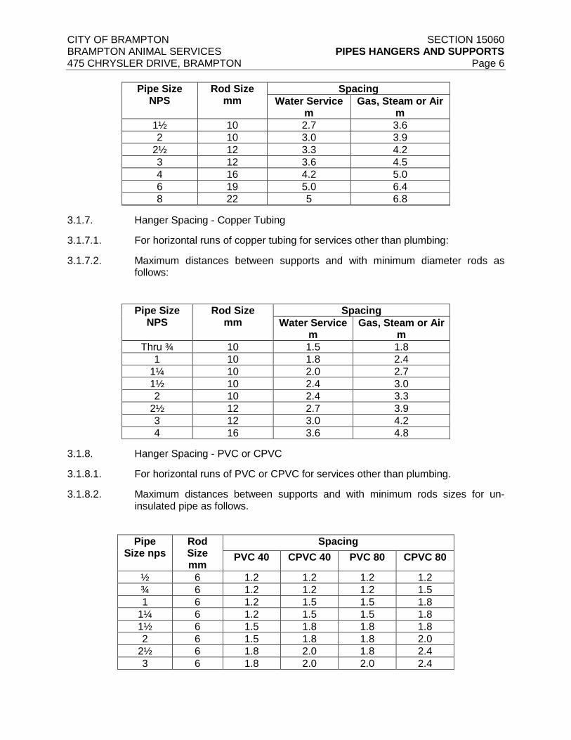
CITY OF BRAMPTON SECTION 15060 BRAMPTON ANIMAL SERVICES PIPES HANGERS AND SUPPORTS 475 CHRYSLER DRIVE, BRAMPTON Page 6
Pipe Size NPS
Rod Size mm
Spacing
Water Service m
Gas, Steam or Air m
1½ 10 2.7 3.6
2 10 3.0 3.9
2½ 12 3.3 4.2
3 12 3.6 4.5
4 16 4.2 5.0
6 19 5.0 6.4
8 22 5 6.8
3.1.7. Hanger Spacing - Copper Tubing
3.1.7.1. For horizontal runs of copper tubing for services other than plumbing:
3.1.7.2. Maximum distances between supports and with minimum diameter rods as follows:
Pipe Size NPS
Rod Size mm
Spacing
Water Service m
Gas, Steam or Air m
Thru ¾ 10 1.5 1.8
1 10 1.8 2.4
1¼ 10 2.0 2.7
1½ 10 2.4 3.0
2 10 2.4 3.3
2½ 12 2.7 3.9
3 12 3.0 4.2
4 16 3.6 4.8
3.1.8. Hanger Spacing - PVC or CPVC
3.1.8.1. For horizontal runs of PVC or CPVC for services other than plumbing.
3.1.8.2. Maximum distances between supports and with minimum rods sizes for un-insulated pipe as follows.
Pipe
Size nps Rod Size mm
Spacing
PVC 40 CPVC 40 PVC 80 CPVC 80
½ 6 1.2 1.2 1.2 1.2
¾ 6 1.2 1.2 1.2 1.5
1 6 1.2 1.5 1.5 1.8
1¼ 6 1.2 1.5 1.5 1.8
1½ 6 1.5 1.8 1.8 1.8
2 6 1.5 1.8 1.8 2.0
2½ 6 1.8 2.0 1.8 2.4
3 6 1.8 2.0 2.0 2.4

CITY OF BRAMPTON SECTION 15060 BRAMPTON ANIMAL SERVICES PIPES HANGERS AND SUPPORTS 475 CHRYSLER DRIVE, BRAMPTON Page 7
Pipe Size nps
Rod Size mm
Spacing
PVC 40 CPVC 40 PVC 80 CPVC 80
4 6 2.0 2.4 2.4 2.7
6 6 2.4 2.4 2.7 3.0
3.1.8.3. For insulated pipe, reduce spacing by 30%.
3.1.8.4. Do not restrain axial movement
3.1.8.5. Spacing based on fluids with specific gravity of 1.0 and 26°C 80°F. For other conditions, use other published data approved by the Consultant.
3.1.9. Anchors and Guides
3.1.9.1. Provide anchors as required to maintain permanent location of pipe lines.
1. Construct anchors for steel or galvanized pipe of approved steel straps and/or rods.
2. For anchoring copper lines, use copper plated anchors, or use insulation bands between tubing and clamps if steel straps or rods are used.
3.1.9.2. Provide minimum two (2) pipe guides on each side of an expansion joint and expansion compensator.
1. 1200 mm between each guide.
2. Not more than 900 mm between last guide and start of expansion joint or expansion compensator.
3.1.9.3. For special expansion joint/compensator or for special applications, where more than two guides on each side are required, follow manufacturer recommendations for location of guides.
3.1.10. Inserts
3.1.10.1. In new construction, set inserts onto formwork prior to pouring of concrete.
1. Provide a 200 mm length of rebar and wire through insert.
3.1.10.2. Mechanical rooms and other areas of multiple pipe runs.
1. Provide continuous type insert channels at 1800 mm intervals alone route of piping.
2. Provide a 200 mm length of rebar and wire through insert.
3.1.11. Upper Attachments - Structural Steel
3.1.11.1. For pipe size NPS 10 and larger supported from structural steel:
1. Provide supplementary structural steel and weld or bolt to structural steel.
2. Submit plan Drawings and details to the Consultant for review.
END OF SECTION
CITY OF BRAMPTON SECTION 15075 BRAMPTON ANIMAL SERVICES MECHANICAL IDENTIFICATION 475 CHRYSLER DRIVE, BRAMPTON Page 1
PART 1 - GENERAL
1.1. SUBMITTALS
1.1.1. Shop Drawings
1.1.1.1. Submit Shop Drawings in accordance 15010 “Basic Mechanical Requirements” and other applicable sections.
1.1.1.2. Submit schedule of Equipment Identification Nameplates for review.
1.1.2. Samples
1.1.2.1. Submit samples of piping, valve and ductwork identification markers.
PART 2 - PRODUCTS
2.1. MATERIALS
2.1.1. Equipment Identification
2.1.1.1. Laminated phenolic plastic with white finish and minimum 10 mm high black letters.
2.1.1.2. Three rows of text, based as shown in equipment Schedules.
1. Line 1: Equipment ID (e.g. P-1)
2. Line 2: Equipment Name (e.g. Northwest Zone Heating Pump)
3. Line 3: Optional, up to 15 characters (e.g. Standby Pump)
2.1.1.3. This identification is in addition to manufacturer’s nameplate data.
2.1.2. Ductwork Identification
2.1.2.1. Painted stencil lettering: 50 mm high.
2.1.2.2. Paint colour:
1. Black paint on canvas covered insulated ductwork
2. White paint on metal covered insulated ductwork
3. White paint on un-insulated ductwork
2.1.2.3. Two levels of text in accordance with designations shown on Schedules:
1. Level 1: Abbreviated name of air handling system for supply systems (e.g. AHU-1), or fan number for exhaust or ventilation only systems (e.g. F-1)
2. Level 2: System name (e.g. General Supply)
2.1.2.4. Direction arrows: 65 mm high
2.1.3. Pipe Identification – Type 1 : Adhesive Labels
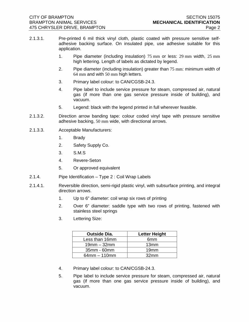
CITY OF BRAMPTON SECTION 15075 BRAMPTON ANIMAL SERVICES MECHANICAL IDENTIFICATION 475 CHRYSLER DRIVE, BRAMPTON Page 2
2.1.3.1. Pre-printed 6 mil thick vinyl cloth, plastic coated with pressure sensitive self-
adhesive backing surface. On insulated pipe, use adhesive suitable for this application.
1. Pipe diameter (including insulation) 75 mm or less: 29 mm width, 25 mm high lettering. Length of labels as dictated by legend.
2. Pipe diameter (including insulation) greater than 75 mm: minimum width of 64 mm and with 50 mm high letters.
3. Primary label colour: to CAN/CGSB-24.3.
4. Pipe label to include service pressure for steam, compressed air, natural gas (if more than one gas service pressure inside of building), and vacuum.
5. Legend: black with the legend printed in full wherever feasible.
2.1.3.2. Direction arrow banding tape: colour coded vinyl tape with pressure sensitive adhesive backing, 50 mm wide, with directional arrows.
2.1.3.3. Acceptable Manufacturers:
1. Brady
2. Safety Supply Co.
3. S.M.S
4. Revere-Seton
5. Or approved equivalent
2.1.4. Pipe Identification – Type 2 : Coil Wrap Labels
2.1.4.1. Reversible direction, semi-rigid plastic vinyl, with subsurface printing, and integral direction arrows.
1. Up to 6” diameter: coil wrap six rows of printing
2. Over 6” diameter: saddle type with two rows of printing, fastened with stainless steel springs
3. Lettering Size:
Outside Dia. Letter Height
Less than 16mm 6mm
19mm – 32mm 13mm
35mm - 60mm 19mm
64mm – 110mm 32mm
4. Primary label colour: to CAN/CGSB-24.3.
5. Pipe label to include service pressure for steam, compressed air, natural gas (if more than one gas service pressure inside of building), and vacuum.

CITY OF BRAMPTON SECTION 15075 BRAMPTON ANIMAL SERVICES MECHANICAL IDENTIFICATION 475 CHRYSLER DRIVE, BRAMPTON Page 3
6. Legend: black with the legend printed in full wherever feasible.
2.1.4.2. Acceptable Manufacturers:
1. Brady
2. Safety Supply Co.
3. S.M.S
4. Revere-Seton
5. Or approved equivalent
2.1.5. Valve Identification
2.1.5.1. Laminated phenolic plastic with minimum 10 mm high lettering, with brass keychain.
2.1.5.2. Minimum two lines of text:
1. Line 1: valve designation
2. Line 2: valve position instruction
2.1.6. Manufacturers
2.1.6.1. Acceptable manufacturers
1. S.M.S.
2. Brady
3. Safety Supply Co.
4. Revere-Seton
5. Or approved equivalent
PART 3 - EXECUTION
3.1. INSTALLATION
3.1.1. Equipment Nameplates
3.1.1.1. Identify mechanical and electrical equipment installed under this Division with nameplates describing the function or use of the particular equipment involved.
3.1.1.2. Do not commence fabrication of nameplates until after receipt of the Consultant's review.
3.1.1.3. Equipment includes, but not limited to:
1. Equipment as shown on schedules and specified
2. Motor starters
3. Motor Control Centres
4. Pushbutton stations
5. Control panels
CITY OF BRAMPTON SECTION 15075 BRAMPTON ANIMAL SERVICES MECHANICAL IDENTIFICATION 475 CHRYSLER DRIVE, BRAMPTON Page 4
6. Time switches
7. Disconnect switches
8. Contactors or relays in separate enclosures
9. Main ducts (i.e. main supply, main return main outdoor air and main exhaust air ducts) for all HVAC systems.
3.1.1.4. Securely fasten nameplates to the equipment with round-head cadmium plated steel self-tapping screws.
3.1.2. Ductwork Identification
3.1.2.1. Label ductwork installed under this Division to indicate the content and direction of flow.
3.1.2.2. Locate labels as follows:
1. Within 1.5 m of air handling units and free standing fans.
2. Within 3 m of divisions in exposed ductwork.
3. On each exposed duct passing through a wall, partition or floor (one on each side of such wall, partition or floor).
4. At intervals not to exceed 15 m along every exposed duct run exceeding 15 m in length.
5. On every concealed duct where it enters a floor area that it serves.
3.1.2.3. Labels to be visible from 1.5 m above the adjacent floor or platform.
3.1.2.4. Clean surfaces with a trisodium phosphate solution before application of paint.
3.1.3. Piping Identification
3.1.3.1. Label all piping installed under this Division to indicate the content and direction of flow with Type 1 or Type 2 labelling system.
3.1.3.2. For piping carrying steam, compressed air and vacuum, show on label the pressure or vacuum, and working units as applicable.
3.1.3.3. Locate labels as follows:
1. At every end of pipe run, adjacent to the valve or item of equipment serviced.
2. At valves, tees and changes of direction.
3. On each exposed pipe passing through a wall, partition or floor (one on each side of such wall, partition or floor).
4. At intervals not to exceed 15 m along every exposed pipe run exceeding 15 m in length.
5. At every access point on concealed piping.
3.1.3.4. Labels to be visible from 1.5 m above the adjacent floor or platform.

CITY OF BRAMPTON SECTION 15075 BRAMPTON ANIMAL SERVICES MECHANICAL IDENTIFICATION 475 CHRYSLER DRIVE, BRAMPTON Page 5
3.1.3.5. Type 1 Labels;
1. Clean surfaces before application of labels.
2. Secure label with direction arrow banding tape for full circumference of pipe, at each end of label.
3.1.3.6. Natural gas piping: as specified above except provide labels every 6 m.
END OF SECTION
CITY OF BRAMPTON SECTION 15730 BRAMPTON ANIMAL SERVICES HVAC EQUIPMENT 475 CHRYSLER DRIVE, BRAMPTON Page 1
1. GENERAL
1. All equipment shall have all the necessary hardware, software, relays, transformers etc as required for complete integration into the existing ‘Delta’ BAS. All BAS/Controls work on the existing Delta Controls system shall be done by ESC Automation. Contact ESC Automation’s Toronto office @ 647) 789-2600.
2. Permits, Equipment Registration and Fees
1. General
1. Make application and pay all required fees for the building permit, any other registration, inspections, etc. for all equipment and systems installed including those required by TSSA.
3. References
1. ANSI/AHRI Standard 410 - Forced Circulation Air-Cooling and Air-Heating Coils.
2. ANSI/AHRI Standard 430 - Central Station Air Handling Units.
3. ANSI/ASHRAE Standard 52.2 - Method of Testing General Ventilation Air-Cleaning Devices for Removal Efficiency by Particle Size.
4. ANSI/ASHARE Standard 62.1 - Ventilation for Acceptable Indoor Air Quality.
5. ANSI/ASHRAE Standard 90.1 - Energy Standard for Buildings Except Low-Rise Residential Buildings.
6. ANSI/NEMA MG 1 - Motors and Generators.
7. ANSI/UL 900 - Standard for Safety Air Filter Units.
8. AHRI Standard 260 - Sound rating of Ducted Air Moving and Conditioning Equipment.
9. ASHRAE Standard 111 - Measurement, Testing, Adjusting, and Balancing of Building HVAC Systems.
10. NFPA 90A - Standard for the Installation of Air Conditioning and Ventilation Systems.
11. UL 1995 - Standard for Safety Heating and Cooling Equipment
4. Submittals
1. Shop Drawings
1. Submit Shop Drawings in accordance with Section 15010 “Basic Mechanical Requirements”.
2. Operation and Maintenance Data:
1. Submit printed operation instructions and maintenance data in accordance with Section 15010 “Basic Mechanical Requirements”.

CITY OF BRAMPTON SECTION 15730 BRAMPTON ANIMAL SERVICES HVAC EQUIPMENT 475 CHRYSLER DRIVE, BRAMPTON Page 2
5. Certifications
1. Air Handling units shall be cETL safety listed to conform with UL Standard 1995 and CAN/CSA Standard C22.2 No. 236.
2. Air handler furnished with double width, double inlet (DWDI) fans and/or plenum fans where applicable, shall be certified in accordance with the central station air handling units certification program, which is based on AHRI Standard 430.
2. PRODUCTS
1. Make-up air Units (MAU-1, MAU-2)-Indirect fired, condensing type, gas heating and self contained, DX cooling.
1. Design, performance criteria, controls, and installation requirements for Custom Air Handling Units.
2. References
1. AMCA Standard 99: Standards Handbook
2. AMCA/ANSI Standard 204: Balance Quality and Vibration Levels for Fans
3. AMCA Standard 210: Laboratory Methods of Testing Fans for Ratings
4. AMCA Standard 300: Reverberant Room Method for Sound Testing of Fans
5. AMCA Standard 500:Test Methods for Louvers, Dampers and Shutters
6. AHRI Standard 410: Forced-Circulation Air-Cooling and Air-Heating Coil
7. AHRI Standard 430: Performance Rating of Central Station Air-handling Unit Supply Fans
8. ASHRAE Standard 52: Gravimetric and Dust Spot Procedures for Testing Air Cleaning Devices Used in General Ventilation for Removing Particulate Matter
9. ASHRAE/ANSI Standard 111: Practices for Measurement, Testing, Adjusting and Balancing of Building Heating, Ventilation, Air-Conditioning and Refrigeration Systems
10. UL Standard 1995: Heating and Cooling Equipment
11. ASTM A-525: Specification for General Requirements for Steel Sheet, Zinc-Coated (Galvanized) by the Hot-Dip Process
3. Submit shop drawings and product data in accordance with Division 1. Submittals shall include the following:
1. Dimensioned plan and elevation view drawings, including motor starter and control cabinets, required clearances, and location of all field connections.

CITY OF BRAMPTON SECTION 15730 BRAMPTON ANIMAL SERVICES HVAC EQUIPMENT 475 CHRYSLER DRIVE, BRAMPTON Page 3
2. Summary of all auxiliary utility requirements such as: electricity, water, compressed air, etc. Summary shall indicate quality and quantity of each required utility.
3. Ladder type schematic drawing of the power and ancillary utility field hookup requirements, indicating all items that are furnished.
4. Manufacturer’s performance of each unit. Selection shall indicate, as a minimum, the following: (I) Input data used for selection. (II) Model number of the unit. (III) Net capacity. (IV) Rated load amp draw. (V) Noise levels produced by equipment. (VI) Fan curves. (VII) Approximate unit shipping weight.
4. Operation and maintenance data
1. Include data on design, inspection and procedures related to preventative maintenance. Operation and Maintenance manuals shall be submitted at the time of unit shipment.
5. Qualifications
1. Manufacturer shall be a company specializing in the design and manufacture of commercial / industrial HVAC equipment. Manufacturer shall have been in production of HVAC equipment for a minimum of 5 years.
2. Each unit shall bear an ETL or UL label under UL Standard 1995 indicating the complete unit is listed as an assembly. ETL or UL listing of individual components, or control panels only, is not acceptable.
6. Delivery, storage, and handling
1. Deliver, store, protect and handle products to site under the supervision of the owner.
7. Sequencing and scheduling
1. Coordinate work performed under this section with work performed under the separate installation contract.
8. Warranty
1. The complete unit shall be covered with labour and material warranty for 24 months as a standard. The warranty period shall start on the date of substantial completion.
9. Acceptable manufacturers
1. Trane-Airwise
2. Carrier
3. MAFNA
CITY OF BRAMPTON SECTION 15730 BRAMPTON ANIMAL SERVICES HVAC EQUIPMENT 475 CHRYSLER DRIVE, BRAMPTON Page 4
10. General
1. Furnish and install where shown on the plans custom make up HVAC units with general construction features as specified below. The units shall be provided and installed in strict accordance with the specifications and meeting the requirements of all local regulations. All units shall be complete with all components and accessories as specified. Any exceptions must be clearly defined. The contractor shall be responsible for any additional expenses that may occur due to any exception made.
11. Factory testing and quality control
1. Standard Factory Tests: The fans shall be factory run tested to ensure structural integrity and proper RPM. All electrical circuits shall be tested to ensure correct operation before shipment of unit. Units shall pass quality control and be thoroughly cleaned prior to shipment.
12. Unit Construction
1. General: Provide factory-fabricated HVAC (100% make-up air) units suitable for outdoor application in an animal care facility. The makeup air units shall be horizontal, gas fired with downflow discharge and shall have the necessary capacity as indicated on the schedule. Units shall have overall dimensions and weights as indicated and the units shall be supplied with a roof curb adaptor if necessary to facilitate installation on to the existing roof curbs. The height of roof curb adaptor shall be kept to a minimum. A suitable unit mounted, ladder/access platform shall be provided to facilitate service access to all components of the unit.
2. Units shall be completely assembled, shall be shipped as a single package.
3. Unit manufacturer shall provide certified ratings conforming to the latest edition of AMCA 210, 310, 500 and AHRI 410. All electrical components and assemblies shall comply with NEMA standards. Unit internal insulation must have a flame spread rating not over 25 and smoke developed rating no higher than 50 complying with NFPA 90A, “Standard for the Installation of Air Conditioning and Ventilating Systems.” Units shall comply with NFPA 70, “National Electrical Code,” as applicable for installation and electrical connections of ancillary electrical components of air handling units. Tags and decals to aid in service or indicate caution areas shall be provided. Units shall be UL or ETL listed.
4. Unit Casing – The construction of the air handling unit shall consist of a Non-skeleton structure made by a “C” or “L” sandwich 1.0 inch thick polyurethane foam with an external side 20 gauge G90 galvanized steel and 22 gauge galvanized steel sheet on the inside, making it a double wall construction. The coating on the exterior surface shall provide a minimum of 2,000 hours Salt Spray rated corrosion resistance (per ASTM B-117). All the elements are connected with
CITY OF BRAMPTON SECTION 15730 BRAMPTON ANIMAL SERVICES HVAC EQUIPMENT 475 CHRYSLER DRIVE, BRAMPTON Page 5
sealed joints.
5. Insulation - Entire unit to be insulated with a full 1” thick closed cell foam insulation. All insulation edges shall be encapsulated within the panel. All field penetrations must be completely sealed by installing contractor.
6. Access Doors - The unit shall be equipped with a solid double wall insulated (same as the unit casing), hinged or latched access doors as shown on the plans. The doorframe shall be extruded aluminum, with a built in thermal break barrier and full perimeter gasket. The door hinge assembly shall be made of composite material.
13. Fan Assemblies
1. Unit Fans – All fans shall meet the air flow performance specified and shall not exceed the break horsepower or sound power levels specified on the mechanical equipment schedule. Fan performance shall be based on testing and be in accordance with AMCA Standards 210 and 300.
2. The fan shall include belt driven fan constructed per AMCA requirements for the duty specified. Fan wheels shall be made of steel material or aluminum construction and rated in accordance with and certified by AMCA for performance. All fans shall be selected to deliver the specified airflow quantity at the specified operating Total Static Pressure and specified fan/motor speed. The fan shall be selected to operate at a system Total Static Pressure that does not exceed 90% of the specified fan’s peak static pressure producing capability at the specified fan/motor speed. Each fan/motor assembly shall include a G90 galvanized steel motor support plate and fan base with internal RIS isolation.
3. All motors shall be high efficiency (to meet ASHRAE 90.1) foot mounted type TEFC selected at the specified operating voltage, RPM, and efficiency as specified or as scheduled elsewhere. Motors shall meet the requirements of NEMA MG-1 Part 30 and 31, section 4.4.2. Motors shall be as manufactured by Baldor, Siemens, Toshiba or WEG. Motor HP shall not exceed the scheduled HP as indicated in the MAU equipment schedule(s). Steel cased motors and/or ODP motors are not acceptable. All motors shall include permanently sealed L10-400,000 hr bearings with shaft grounding to protect the motor bearings from electrical discharge machining due to stray shaft currents Provide shaft grounding rings on all motor sizes. Each fan wheel shall be dynamically balanced to BV-5 or better.
4. Unless specified in the electrical specifications, provide a single point power supply to each unit complete with a weather-proof, unit mounted disconnect switch. Provide a separately wired, unit mounted service receptacle for each unit.
5. Wire sizing shall be determined, and installed, in accordance with applicable NEC standards and local code requirements.
14. Heating section
CITY OF BRAMPTON SECTION 15730 BRAMPTON ANIMAL SERVICES HVAC EQUIPMENT 475 CHRYSLER DRIVE, BRAMPTON Page 6
1. Provide an in-direct fired, condensing type, forced draft, natural gas fired burner complete with stainless steel heat exchanger, necessary safety and control elements.
2. Select gas system components to suit existing gas supply on site.
15. DX cooling system
1. Provide a self contained, direct expansion type cooling system with R410A or R407A refrigerant, stacked unit mounted air cooled condensing unit, DX cooling coil section with stainless steel drain pan,
2. DX cooling section shall be complete with associated compressors, condensers, DX coil, insulated refrigeration piping, vibration isolators and refrigeration accessories and safety and diagnostic controls.
16. Drain Pans
1. The drain pan shall be fabricated from stainless steel. All pans are to be pitched for complete drainage with no standing water in the unit. Provide stainless steel drain connection extended to the exterior of the casing. All drain connections shall be piped and trapped separately for proper drainage.
17. Filters
1. Provide minimum MERV 8 filters in galvanized steel frames with retaining clips. Factory fabricated filter sections shall be of the same construction and finish as the unit. Side service filter racks shall be fabricated from galvanized steel and include hinged access doors. Internal blank-offs shall be provided by the make up air unit manufacturer as required to prevent air bypass around the filters.
18. Dampers
1. Dampers shall be airfoil, opposed blade type. Frame and dampers to be constructed out of extruded 6060-T66 aluminum. Damper blades to be connected by FRP nylon infused gears for long life. Dampers to have square actuator shaft to prevent actuator slippage. Dampers to be AMCA certified.
2. Dampers shall be Ultra-low leakage Class 1A (less than 3 cfm/sq ft. @ 1” w.g.). Ultra-low leakage dampers shall have insulated, extruded aluminum airfoil blades. Flat or formed metal blades are not acceptable. The damper blade shall incorporate rubber edge seals and Aluminum, zinc plated or stainless steel square steel shaft for a non-slip operation. Shaft bearings shall be spherical – non corrosive nylon to eliminate friction and any metal to metal contact.
19. Electrical power and controls
1. All electrical and automatic control devices not previously called out or listed below are to be furnished and installed in the field by OTHERS.
2. All wiring shall be (75°C) Insulated copper wires.
CITY OF BRAMPTON SECTION 15730 BRAMPTON ANIMAL SERVICES HVAC EQUIPMENT 475 CHRYSLER DRIVE, BRAMPTON Page 7
3. The unit shall feature a mounted permanent nameplate displaying at a minimum the manufacturer, serial number, model number and current and amps voltage. The unit must have an ETL or UL Listing and bear the appropriate mark.
4. Conduit shall consist of a combination of EMT or flexible metal conduit as required. Liquidtite flexible metal conduit may be used outside the air tunnel for wet locations.
5. The unit shall feature a main non-fused disconnect of the proper amp rating to allow shutoff of all electrical motors and VFDs.
6. The fan motor shall be wired to a motor disconnect mounted on unit exterior.
7. Unit Convenience Features (I) Fan section light shall be controlled by one light switch
mounted adjacent to the supply air fan access door. At the same box the convenience 115V outlet is located. All other access section lights shall be field wired.
3. EXECUTION
1. Installation
1. Refer to all other related sections (e.g. identification, motors and wiring, start-up and commissioning and refrigerant piping).
2. Make-up air unit shall be factory assembled and tested prior to shipment to site.
3. Control Wiring / BAS Work
1. Coordinate details of controls/BAS with the existing Delta systems and provide all required controls, electric hardware, gas components, refrigerant components, and accessories to fully integrate the proposed units into the existing BAS.
2. The contractor shall be responsible for the interconnecting control wiring between remote controllers, centralised control and relevant components. This work shall be co-ordinated with the Electrical / Controls Contractor for the rooting and trunking of the cables prior to finalization of order for the units.
3. All control wiring are to be carried out in 2 core 16 AWG shielded cabling with colour coding and tagged with ID number at 3 metre intervals as per schematics for ease of identification and maintenance.
4. Control wiring shall not be run next to power wiring. A minimum space of 100mm between both control and power cables shall apply.
5. Install all equipment as indicated on the Drawings and as per the manufacturer's instructions.

CITY OF BRAMPTON SECTION 15730 BRAMPTON ANIMAL SERVICES HVAC EQUIPMENT 475 CHRYSLER DRIVE, BRAMPTON Page 8
4. Manufacturer to certify installation of units and also supervise the actual start-up and commissioning of the units.
5. Install and wire all accessories shipped lose with units for fully operating systems.
End of Section

CITY OF BRAMPTON SECTION 15800 BRAMPTON ANIMAL SERVICES WALK-IN FREEZER 475 CHRYSLER DRIVE, BRAMPTON Page 1
1. General
1. Provide an engineered walk-in freezer for the suitable for transportation and storage of un-cut, large animal carcasses (e.g. deer).
2. Permits, Equipment Registration and Fees
1. General
1. Make application and pay all required fees for related approvals and permits, any other registration, inspections, etc. for all equipment and systems installed by authorities having jurisdiction.
3. Submittals
1. Shop Drawings
1. Submit Shop Drawings in accordance with Section 15010 “Basic Mechanical Requirements”.
2. Operation and Maintenance Data:
1. Submit printed operation instructions and maintenance data in accordance with Section 15010 “Basic Mechanical Requirements”.
4. Certifications
1. ESA certification.
2. Products
1. Acceptable manufacturers
1. Francis Restaurant Industry Equipment Services Inc. (F.R.I.E.S. Inc.) (905)-838-2060.
2. Or approved equivalent
2. General
1. Furnish and install engineered walk-in freezer as shown on the plans complete with roof mounted air cooled condensing unit and all associated refrigerant piping, accessories and controls.
3. Unit Construction
1. Walk-in Freezer/Freezer combination with a white embossed enamel interior and exterior finish, containing 3” (76mm) foamed in place polyurethane.
2. Approx. Exterior Dimensions: 132.25” x 149.5” x 101”
3. Approx. Interior Dimension: 126.25” x 143.25” x 95”
4. Floor construction: 3” (76mm) insulated, galvanized clad floor complete with ½” plywood underlay reinforcement. Floor also complete with Aluminum checkered plate down the corridor. NOTE: Refrigeration standard floors are designed to withstand only 300lbs./sq./ft. stationary

CITY OF BRAMPTON SECTION 15800 BRAMPTON ANIMAL SERVICES WALK-IN FREEZER 475 CHRYSLER DRIVE, BRAMPTON Page 2
load, and not suitable for heavy point loads or trucking.
5. Ramp: Walk-in freezer shall be complete with one interior ramp clad in aluminum tread plate.
6. Doors: Freezer shall be complete with one standard double door of approximate size 72” x 78” in-fitting door with magnetic gasket, door closer c/w top Freezers door with door frame heaters and prewired heated vent port.
7. Lights: Lights shall be provided on the door panel complete with an interior vapour proof LED light fixture wired to a pilot light and motion sensor switch ready for final connection by others. Wire guards shall be included for the light and the light shall be pre-wired to junction box on top of the walk-in freezer.
8. Thermometers: One digital thermometer shall be provided on the external surface of the door.
(I) Temperature sensor and alarm for the walk-in freezer shall be provided to be monitored by the BAS.
9. Warranties: Provide one year parts and labour warranty for the entire unit and provide a five year warranty for the motor and compressor.
10. Refrigeration: Remote Outdoor system shall be suitable for installation on the building roof.
11. Controls: Provide engineered freezer controls (safety and diagnostic). Freezer shall be complete with “KE2”- Adaptive Electronic Controllers.
12. Power supply: 208-230/3/60,
13. Max HP (Indoor unit): ¼.
14. Max HP (Outdoor unit): 5.
15. Refrigerant: R404A.
16. Freezer room design temperature: -18C.
3. Execution
1. Installation
1. Refer to all other related sections (e.g. identification, motors and wiring, start-up and commissioning and refrigerant piping).
2. Walk-in freezer shall be assembled at site by factory trained and certified technicians of the unit manufacturer.
3. Review existing floor and modify the same with materials to match existing to ensure that the freezer floor is perfectly horizontal.
4. Install outdoor units on a suitable zero penetration support frame.
5. Install refrigerant piping in a neat manner and seal the roof penetration using RIBA V-seal or approved equal sealing products.
6. The Contractor is responsible for all interconnecting control wiring between

CITY OF BRAMPTON SECTION 15800 BRAMPTON ANIMAL SERVICES WALK-IN FREEZER 475 CHRYSLER DRIVE, BRAMPTON Page 3
various freezer components.
1. All control wiring shall be carried out in 2 core 16 AWG shielded cabling with colour coding and tagged with ID number at 3 metre intervals as per schematics for ease of identification and maintenance.
2. Control wiring shall not be run next to power wiring. A minimum space of 100mm between both control and power cables shall apply.
3. Install all equipment as indicated on the Drawings and as per the manufacturer's instructions.
7. Manufacturer to certify installation of the freezer and shall supervise the actual start-up and commissioning of the units.
8. Install and wire all accessories shipped lose with units for fully operating systems.
End of Section
CITY OF BRAMPTON SECTION 15990 BRAMPTON ANIMAL SERVICES START-UP AND PERFORMANCE TESTING 475 CHRYSLER DRIVE, BRAMPTON Page 1
PART 1 - GENERAL
1.1. GENERAL
1.1.1. Perform the Work of this Section including but not limited to the following:
1.1.1.1. Performance testing balancing and commissioning of complete vehicle wash system, associated piping
1.1.1.2. Survey of installed automatic controls and verification of functional performance
1.1.1.3. Measuring and reporting all specified space noise levels
1.1.1.4. Test performance of all vibration isolation equipment
1.1.1.5. Rechecking of testing and balancing during the alternate (heating/cooling) season
1.2. RELATED WORK IN OTHER SECTIONS
1.2.1. Factory testing, and calibrating of equipment or control systems.
1.2.2. Testing and checking of equipment supplied by other Divisions, except where such equipment forms an integral part of the mechanical systems.
1.3. COORDINATION
1.3.1. The Contractor shall provide the following assistance and/or services to the Testing and Balancing firm.
1.3.1.1. Schedule sufficient time so that initial testing and balancing can be completed before occupancy begins and coordinate with trades involved.
1.3.1.2. Keep Testing and Balancing firm informed of any major changes made during construction and furnish same with a set of Project Drawings and reviewed Shop Drawings.
1.3.1.3. Furnish balancing devices, test connections access openings, balancing probe inlets and plugs.
1.3.1.4. Clean and pre-run all equipment, filters, etc. and place all heating, ventilating and air conditioning systems into full operation and continue same during each working day of testing and balancing.
1.3.1.5. Provide immediate labour from pertinent mechanical trades and tools, equipment and materials to make equipment and system alterations and adjustments, as required including control adjustments.
1.3.1.6. Building Management System technical representative to operate the BMS during air and water balancing testing.
1.3.1.7. Make available all equipment data (Shop Drawing Performance Data and operating instructions) to the Testing and Balancing Firm.
1.3.1.8. Fuel fired heating equipment manufacturer service representative, or other

CITY OF BRAMPTON SECTION 15990 BRAMPTON ANIMAL SERVICES START-UP AND PERFORMANCE TESTING 475 CHRYSLER DRIVE, BRAMPTON Page 2
qualified service company technical representative, for performance testing of heating equipment. Testing and Balancing Firm witnesses and records all test results.
1.3.2. As part of the coordination effort, the Contractor shall be fully responsible for systems constructed, installed and adjusted to provide optimum performance as required by design intent. Any re-adjusting required as the result of spot checks by the Consultant shall be done at no increase in Contract Price.
1.4. SUBMITTALS
1.4.1. Submit layout Drawings and Report Format a minimum 14 days prior to start of air and water balancing on-site.
1.4.1.1. Report Format
1. Submit proposed format of initial report.
2. Include a complete list of instruments and tests for which they are to be used as they relate to this Project, including date of last calibration
PART 2 - PRODUCTS
2.1. NOT APPLICABLE.
PART 3 - EXECUTION
3.1. REQUIRED REPORTS
3.1.1. Provide the following Start-Up and Performance Testing reports:
3.1.1.1. Equipment start-up report
3.1.1.2. Authorities report
3.1.1.3. Air and water balancing report
3.1.1.4. Controls operation report
3.1.1.5. Alternate Season test report
3.1.2. Report Format
3.1.2.1. Prepare test forms in MS Excel or Word format. Results of tests may be filled in by hand.
3.1.2.2. Include the following header information for each test report:
1. Owner Name
2. Project Name
3. Contractor Name
4. Consultant Name
5. Name of Test Report
CITY OF BRAMPTON SECTION 15990 BRAMPTON ANIMAL SERVICES START-UP AND PERFORMANCE TESTING 475 CHRYSLER DRIVE, BRAMPTON Page 3
3.1.2.3. Include the following on the front sheet of the consolidated report:
1. Contractor Company Name
2. Name and signature of the person submitting the report
3. Date of report
4. The following statement: “The undersigned certifies that the test results recorded in this report are correct and that results have been witnessed by the trade responsible for the test”.
3.1.3. Submit the above tests in a hardcopy form, separately bound from the Operations and Maintenance manuals, and in Adobe Acrobat PDF format, in accordance with Section 15010 “Basic Mechanical Requirements”.
3.2. EQUIPMENT START-UP REPORT
3.2.1. Provide a consolidated test report for all equipment, including the following start-up tests:
3.2.1.1. Equipment/System Summary tests
3.2.1.2. Equipment/System start-up test.
3.2.1.3. Manufacturer’s start-up test
3.2.2. Equipment/System Summary Tests
3.2.2.1. Provide a test report in spreadsheet format which summarizes the following data for each piece of equipment which is powered or has automatic controls:
1. Equipment ID and name
2. Motor rotation (bump test) - result and initialled by the Contractor
3. Equipment Start-Up report status - status and initialled by the Contractor
4. Manufacturer Start-Up report status – status and initialled by the Contractor
5. Test completion date
3.2.2.2. Provide a test report in spreadsheet format which summarizes the following data for pressure testing of piping systems:
1. System name
2. System limits (if system is not tested in its entirety)
3. Type of test (pneumatic, hydrostatic)
4. Pressure at start of test
5. Pressure at end of test
6. Duration of test
7. Contractor dated and initialled.
3.2.2.3. Provide a test report in spreadsheet format which summarizes the following tests
CITY OF BRAMPTON SECTION 15990 BRAMPTON ANIMAL SERVICES START-UP AND PERFORMANCE TESTING 475 CHRYSLER DRIVE, BRAMPTON Page 4
for equipment served by liquid, gas or vapour systems
1. Equipment ID and name
2. Isolation valves are in the open position – status and initialled by the Contractor
3. Backflow preventers have been tested - status and initialled by the Contractor
4. Pressure relief valves installed – record setpoint and initialled by the Contractor
3.2.3. Equipment/System Start-Up Test Report
3.2.3.1. Provide a separate start-up report for each piece of the following equipment. The SMACNA “Systems Ready to Balance Check List”, where applicable, may be used for this report.
1. Pumps
2. Air compressors
3. All equipment related to vehicle wash system.
4. Hydronic piping systems
3.2.4. Manufacturer’s Start-Up Test
3.2.4.1. Provide a separate start-up report for each piece of the vehicle wash equipment, utilizing the manufacturer’s start-up check list. This report may be prepared by the manufacturer’s service representative.
3.3. AUTHORITIES REVIEW
3.3.1. Submit copies of authorities-having-jurisdiction inspection and test reports, including:
3.3.1.1. Plumbing and drainage municipal inspector reports
3.3.1.2. TSSA pressure vessel and piping inspection reports
3.3.1.3. ESA field certification reports
3.4. AIR AND WATER BALANCING
3.4.1. Provide air and water balancing report in PDF format.
3.5. DEFICIENCIES
3.5.1. Immediately report to the Consultant, any deficiencies in the systems or equipment performance resulting in design requirements being unobtainable.
3.6. DRAFT REPORT
3.6.1. On completion of the start-up, testing, adjusting and balancing of all systems, submit to the Consultant, two (2) typewritten copies of a full report on all tests, adjustments, and balancing performed, including the following:

CITY OF BRAMPTON SECTION 15990 BRAMPTON ANIMAL SERVICES START-UP AND PERFORMANCE TESTING 475 CHRYSLER DRIVE, BRAMPTON Page 5
3.6.1.1. Summary of all systems
3.6.1.2. Testing methods and instrumentation
3.6.1.3. Start-Up reports
3.6.1.4. Authorities Having Jurisdiction reports
3.6.1.5. Air systems testing and balancing data
3.6.1.6. Liquid systems testing and balancing data
3.6.1.7. Attachments including systems schematics with numbered terminals for referring to data above.
3.6.2. After review by the Consultant and at the Consultants direction, retest up to 10% of all measurements in locations as directed by the Consultant, at no cost extra to the Contract.
3.7. INTERIM REPORT
3.7.1. After completion of any retesting described above, submit three (3) typewritten copies of the interim report, in a 3-hole “D” style binder and two (2) CD-R electronic copies in Adobe Acrobat ver.6 PDF format.
3.7.2. This report is required to obtain Substantial Performance of the Contract.
3.8. FINAL REPORT
3.8.1. Submit to Consultant following completion of alternate season testing and balancing. Submit three (3) typewritten copies and two (2) CD-R Adobe PDF in the same formats as the initial report specified above.
3.9. SPOT CHECK
3.9.1. Before acceptance of the air and water balancing report, the Consultant may request to witness spot-checks of the report results.
3.9.2. If results indicate unusual testing inaccuracy, omissions, or incomplete balancing/adjustment, in the opinion of the Consultant, re-balance entire affected system(s) at no increase in Contract Price.
3.10. ACCEPTANCE
3.10.1. The Substantial Performance of the Mechanical Work will be considered reached when the interim Start-Up and Performance Testing report is accepted by the Consultant and in the opinion of the Consultant all systems have been satisfactorily installed, operated tested, balanced, and adjusted to meet the specified and intended performance.
3.10.2. The substantial performance will not depend upon alternate season testing as specified hereafter, however, make such relevant repairs or modifications deemed necessary during this re-checking as part of the guarantee of the Work.
3.10.3. The total performance of the Contract will not be considered reached until the

CITY OF BRAMPTON SECTION 15990 BRAMPTON ANIMAL SERVICES START-UP AND PERFORMANCE TESTING 475 CHRYSLER DRIVE, BRAMPTON Page 6
alternate season testing and balancing is completed and the final report submitted and accepted by the Consultant.
3.11. ADDITIONAL TESTING
3.11.1. The Consultant may request such additional testing in connection with this Project as deemed necessary.
END OF SECTION

CITY OF BRAMPTON SECTION 15995 BRAMPTON ANIMAL SERVICES COMMISSIONING 475 CHRYSLER DRIVE, BRAMPTON Page 1
PART 1 - GENERAL
1.1. RELATED WORK
1.1.1. Provide work of this Section in accordance with the Contract Documents.
1.1.2. This specification covers commissioning of mechanical systems which are part of the Work.
1.1.3. Commissioning work shall be a team effort to ensure that all equipment and systems have been completely and properly installed, function correctly to meet the design intent, and to document system performance parameters for fine tuning of control sequences and operational procedures.
1.1.4. The Commissioning process develops, coordinates, and documents the following:
1.1.4.1. Equipment start-up
1.1.4.2. Control system calibration
1.1.4.3. Testing and balancing
1.1.4.4. Verification and Performance Testing
1.1.4.5. Operation documentation
1.1.4.6. Operator training
1.1.5. Mechanical system installation, start-up, testing, balancing, preparation of O&M manuals and operator training are the responsibility of the Division 15 Contractors, with the coordination of the commissioning process the responsibility of the Commissioning Authority in conjunction with the Construction Manager.
1.1.6. The Commissioning Program is divided into four parts:
1.1.6.1. Part 1: Verification Testing
1.1.6.2. Part 2: Performance Testing
1.1.6.3. Part 3: Systems Operating Manuals
1.1.6.4. Part 4: Operator Training
1.2. SUBSTANTIAL COMPLETION
1.2.1. Substantial completion of the Division 15 work requires the following parts of the Commissioning Program to be completed and accepted by the Owner:
1.2.1.1. Part 1: Verification Testing
1.2.1.2. Part 4: Operator Training
1.2.2. Part 2 – Performance Testing may begin before Substantial Completion and

CITY OF BRAMPTON SECTION 15995 BRAMPTON ANIMAL SERVICES COMMISSIONING 475 CHRYSLER DRIVE, BRAMPTON Page 2
extend upwards of nine (9) months after Substantial Completion, based on seasonal conditions required to obtain test load conditions.
1.3. WORK INCLUDED
1.3.1. Commissioning work of Division 15 includes, but is not limited to:
1.3.1.1. Testing and start-up of equipment.
1.3.1.2. Testing, adjusting and balancing of water piping.
1.3.1.3. Cooperation with the Commissioning Authority in developing and implementation of the commissioning plan.
1.3.1.4. Providing qualified personnel for participation in commissioning tests, including seasonal testing required after the initial testing.
1.3.1.5. Providing equipment, materials, and labour as necessary to correct construction and/or equipment deficiencies found during the commissioning process.
1.3.1.6. Providing operation and maintenance manuals, Systems Operating Manuals, and as-built drawings to the Commissioning Authority for verification.
1.3.1.7. Providing training and demonstrations for the systems specified in this Division.
1.3.1.8. Provisions for a 48 hour normal operating day test shall be performed on all the systems to ensure that the systems operate as per design requirements.
1.3.2. Conduct complete and thorough evaluation and documentation of the operation and performance of all components, systems, and sub-systems, including, but not limited to, the following equipment:
1.3.2.1. Pumps
1.3.2.2. Air compressor
1.3.2.3. Detergent module and arches.
1.3.2.4. High rinse arches.
1.3.2.5. Water softener.
1.3.3. Commissioning documentation includes but is not limited to:
1.3.3.1. Progress and status reports, including deficiency lists
1.3.3.2. Verification of Pre-start and Start-up procedures and results
1.3.3.3. Performance testing procedures and results
1.3.3.4. Training agenda and materials
1.3.3.5. As-built records
1.3.3.6. Final Commissioning report

CITY OF BRAMPTON SECTION 15995 BRAMPTON ANIMAL SERVICES COMMISSIONING 475 CHRYSLER DRIVE, BRAMPTON Page 3
1.3.3.7. Systems Operating Manuals
1.3.3.8. Operation and maintenance manuals
1.4. RELATED WORK
1.4.1. Start-Up and Performance Testing Section 15990
1.5. REFERENCE STANDARDS
1.5.1. Comply with the latest edition of the following:
1.5.1.1. ASHRAE Guideline 1-1996 The HVAC Commissioning Process, as amended herein.
1.6. REPORTING SOFTWARE
1.6.1. Commissioning documentation to be developed and recorded using the following software:
1.6.1.1. MS Word
1.6.1.2. MS Excel
1.6.1.3. MS Access
1.6.1.4. Adobe Acrobat version 6 – for scanned documents
1.6.1.5. Photos – scanned or digital - *.jpg format
1.7. DOCUMENTATION DELIVERABLES
1.7.1. Identify documents including test documents, binder covers, etc. using equipment ID numbers provided on equipment schedules.
1.7.2. Scan original signed test reports, including verification and performance test reports, manufacturers service reports, etc. in Adobe Acrobat *.pdf version 6 format. For original document chapters, provide Adobe chapter referencing.
1.7.3. Digital File Naming Convention:
1.7.3.1. Store documents with filenames which include the equipment type, ID number, and type of document.
1.7.3.2. Equipment Type
1. PS – Process Systems, piping, compressed air
2. FP – Fire Protection
3. PD – Plumbing and Drainage
4. HG – Heating Generation
5. CG - Cooling Generation
6. HV – HVAC
7. BMS – Building Management System
CITY OF BRAMPTON SECTION 15995 BRAMPTON ANIMAL SERVICES COMMISSIONING 475 CHRYSLER DRIVE, BRAMPTON Page 4
1.7.3.3. Equipment ID:
1. As per equipment schedules/drawings.
1.7.3.4. Document Type:
1. VT – Verification Test
2. PT – Performance Test
3. SOM – Systems Operating Manual
4. TM – Training Manual/Material
1.7.3.5. Example : A verification test report for air conditioning unit No. 1
1. HV-AC1-VT.*
1.7.4. Submit three (3) copies of each Verification and Functional Performance Test reports, both preliminary and final issues.
1.7.4.1. Collate final, accepted and signed test results in separate binders as follows:
1. Fire Protection
2. Plumbing and Drainage
3. HVAC Systems
4. Building Management Systems
1.7.5. Submit one (1) draft copy of the SOM in a 8 ½” x 11” D-ring binder for review. All documents are to be stamped or watermarked as “DRAFT” and identified by issue date and revision letter.
1.7.6. Submit the final three (3) copies of the SOM in a 8 ½” x 11” D-ring binder, white, with insert sleeves on the cover and spine. Provide inserts for the front cover and spine in a form approved by the Commissioning Authority.
1.7.7. Provide three (3) CD-R or DVD-R copies of all commissioning documentation. File the documents in directories as follows:
1.7.7.1. Primary directories : Verification / Performance / SOMS / Training
1.7.7.2. Sub-directories : Fire / Plumbing / HVAC / BMS
1.8. SUBMITTALS
1.8.1. Report Samples
1.8.1.1. Provide sample test documentation for each type of equipment and system for review by the Commissioning Authority prior to the start of the Verification Process
1. Pre-start and start-up procedure check list form
2. Verification Test method and results form
3. Functional Performance Test method and results form

CITY OF BRAMPTON SECTION 15995 BRAMPTON ANIMAL SERVICES COMMISSIONING 475 CHRYSLER DRIVE, BRAMPTON Page 5
4. Operating and Maintenance Manual
PART 2 - PRODUCTS
2.1. TEST EQUIPMENT - GENERAL
2.1.1. Furnish all special tools and equipment required during the commissioning process.
2.1.2. Submit a list of tools and equipment to be used during the commissioning process to the Commissioning Authority for approval.
2.1.3. Utilities (water, gas, fuel oil, electrical power) will be provided by the Owner
2.2. TEST EQUIPMENT – PROPRIETARY
2.2.1. Provide any proprietary test equipment and software required by any equipment manufacturer for programming and/or start-up, whether specified or not.
2.2.2. The Manufacturer shall provide the test equipment, demonstrate its use, and assist in the commissioning process as needed.
2.2.3. Proprietary test equipment and software shall become the property of the Owner upon completion of the commissioning process.
PART 3 - EXECUTION
3.1. GENERAL
3.1.1. Complete all phases of work so that the systems can be started, tested, balanced, and owner’s acceptance procedures be undertaken.
3.1.2. Participate and assist in the development of the Commissioning Plan by the Commissioning Authority, by providing all necessary information pertaining to the equipment and installation. Provide commissioning schedule information to be incorporated into the overall Commissioning Plan schedule.
3.1.3. Acceptance procedures may begin prior to completion of a system and/or sub-system. Start of acceptance procedures before system completion does not relieve the Contractor from completing those systems in accordance with the commissioning and construction schedule.
3.2. COMMISSIONING MEETINGS
3.2.1. Pre-construction
3.2.1.1. Participate in a pre-construction meeting of all commissioning team members, to familiarize all parties with the commissioning process, and to ensure that the responsibilities of each party are clearly understood.
3.2.2. Construction and Post-Construction
3.2.2.1. Participate in commissioning meetings as scheduled by the Commissioning Authority and Construction Manager. Identify to the commissioning group problems relating to the commissioning schedule, identification of start-up issues,
CITY OF BRAMPTON SECTION 15995 BRAMPTON ANIMAL SERVICES COMMISSIONING 475 CHRYSLER DRIVE, BRAMPTON Page 6
etc, and participate in the resolution of these problems.
3.3. PARTICIPATION IN ACCEPTANCE PROCEDURES
3.3.1. Provide skilled technicians to start-up and debug all systems within the Division 15 scope of Work. Include for labour, materials, and subsistence costs for these same technicians to assist the Commissioning Authority in completing the commissioning program.
3.3.2. Provide details regarding work schedules, time commitments, work sequence programming, etc, to the Commissioning Authority, to permit the development and monitoring of a coordinated commissioning schedule.
3.3.3. Ensure the qualified technician(s) are available and present during commissioning testing to complete the tests, make adjustments and to assist in problem resolutions.
3.3.4. Should any equipment or system experience performance problems and/or reconstruction or replacement of comments is required, include for additional technician time for subsequent retesting of systems until required system performance is achieved.
3.3.5. The Commissioning Authority reserves the right to approve proposed technicians with regard to the technical skill level required for each type of equipment and/or system, and a willingness by the individual(s) to work within the Commissioning Group.
3.4. PROBLEM RESOLUTION
3.4.1. In the event that additional work is required to correct systems, misapplied equipment, and/or deficient performance under varying load conditions, this work will be carried out under the direction of the Owner. Assist the Owner and Commissioning Authority in developing an acceptable resolution to the problem, including the resources of equipment suppliers.
3.4.2. The Owner and/or the Consultant has final jurisdiction over any additional work required to achieve the required level of performance.
3.4.3. Complete corrective work in a timely fashion to permit the completion of the commissioning process.
3.5. SEASONAL COMMISSIONING
3.5.1. For out-of-season system performance testing, conduct initial performance tests to demonstrate off-peak load performance. Schedule peak load performance testing over the succeeding nine (9) months to ensure all equipment is tested at peak load prior to the expiry of the construction contract warranty. Should any deficiencies be found during the seasonal commissioning, the warranty will be extended by the manufacturer.
3.5.1.1. Alternatively, provide temporary equipment (load banks, etc.) to simulate full load conditions. Submit proposed methodology for review by the Commissioning Authority and Consultant.

CITY OF BRAMPTON SECTION 15995 BRAMPTON ANIMAL SERVICES COMMISSIONING 475 CHRYSLER DRIVE, BRAMPTON Page 7
3.6. REPORT FORMAT
3.6.1. Provide separate checklists for each piece of equipment and system tested, including interfaces, interlocks, etc.
3.6.1.1. For checklists generated in MS Excel format, provide a separate file for each piece of equipment; do not store multiple pieces of equipment on separate worksheets in the same file.
3.6.2. Each item to be checked will be recorded on a separate entry line and include the following information, reading from left to right across the entry:
3.6.2.1. Checklist item No.
3.6.2.2. Test description
3.6.2.3. Test status – “Pass”, “Fail”, “Not Applicable”
3.6.2.4. Deficiency status – “Major”, “Minor”
3.6.2.5. Comments
3.6.3. Deficiency definitions:
3.6.3.1. “Major” – an item which if not corrected renders the equipment or system unsuitable or un-safe for use by the Owner. Major deficiencies must be corrected as a condition for achieving Substantial Completion.
3.6.3.2. “Minor” – an item which does not impact on the operation of the equipment or system and will allow the Owner to use the system safely. Minor deficiencies may be corrected before or after Substantial Completion, but will not prevent certification of Substantial Completion of the Work. These items must be rectified in a timely manner.
3.7. VERIFICATION TESTS (PART 1)
3.7.1. Scope of Work
3.7.1.1. Conduct operating tests and checks to verify that all components, equipment, systems, and interfaces between systems, operate in accordance with contract documents.
3.7.1.2. Tests to demonstrate and verify all operating modes, interlocks, specified control sequences, specific responses to abnormal or emergency conditions, and verification of the proper response of the Building Automation System.
3.7.1.3. Validate the results of the TAB report.
3.7.1.4. Roles and Responsibilities:
Verification Testing
Organized by: Commissioning Authority
Test sheets provided by:
Division 15 contractors
Testing Conducted by: Division 15 contractors

CITY OF BRAMPTON SECTION 15995 BRAMPTON ANIMAL SERVICES COMMISSIONING 475 CHRYSLER DRIVE, BRAMPTON Page 8
Verification Testing
Testing Recorded by: Division 15 contractors
Tests Witnessed by: Commissioning Authority Design Consultant (optional) Owner (optional)
Reports reviewed by: General Contractor/Construction Manager Commissioning Authority Design Consultant
Reports accepted by: Owner
3.7.2. Submittals:
3.7.2.1. Submit a copy of each type of equipment and system verification report for approval by the Owner prior to commencement of the Verification Tests.
3.7.2.2. Include any specific test requirements provided by the Owner and/or Consultant in the test reports. These requirements will be provided in MS Word or Excel format.
3.7.3. Participants in Verification tests:
3.7.3.1. Commissioning Authority: schedules tests and assembles commissioning team members who are responsible for the implementation, witnessing and documenting the tests.
3.7.3.2. Mechanical contractor: provide the services of qualified technician(s) who are familiar with the construction and operation of the system. Provide access to the contract plans, shop drawings, and equipment cut sheets of all installed equipment.
3.7.3.3. Controls contractor: provide the services of qualified technician(s) who are familiar with the Work. Provide details of the control system, schematics, and a narrative description of control sequences of operation.
3.7.3.4. Electrical contractor: provide a foreman electrician familiar with the electrical interlocks, interfaces with emergency power supply, and interfaces with alarm and life-safety systems. Provide access to the contract plans, and all as-built schematics of sub-systems, interfaces and interlocks.
3.7.3.5. Equipment suppliers: provide the services of manufacturers’ service personnel to provide assistance with pre-start and initial start-up of the equipment, as required.
3.7.4. Documentation and Reporting Requirements.
3.7.4.1. Provide separate test records for each piece of equipment and system.
3.7.4.2. Information used to develop the check lists are to include material from the following sources:
1. Manufacturers installation requirements
2. Contractor’s own checklists
CITY OF BRAMPTON SECTION 15995 BRAMPTON ANIMAL SERVICES COMMISSIONING 475 CHRYSLER DRIVE, BRAMPTON Page 9
3. Design consultants checklists
4. Owners checklists
3.7.4.3. Checklists to include the following information:
3.7.4.4. Front cover sheet – Project name, Owner name, equipment ID and name, test date(s), and space for sign-off signatures and dates as follows:
1. Mechanical Contractor – “Submitted by:”
2. General Contractor / Construction Manager – “Reviewed by:”
3. Design Consultant – “Reviewed by”
4. Commissioning Authority – “Reviewed by”
5. Owner – “Accepted by”
3.7.4.5. Second and subsequent pages to include tests as defined below.
3.7.4.6. Equipment Checklists:
1. Motor, power and drives
2. Equipment piping, between equipment isolation valves
3. Installation pre-start tests specific to the class of equipment
4. Equipment start-up tests specific to the class of equipment
5. Electrical audit for CSA label or ESA field approval label
6. Gas and fuel fired equipment audit for CSA/CGA approvals, or TSSA field approvals
7. Expansion tank installation and settings
8. Operator training, including attendee names and dates, and details of manufacturers equipment demonstrations
9. Status of As-built documentation, and Operating and Maintenance Manuals reviews
3.7.4.7. Piping System Checklists:
1. Hydrostatic and/or pneumatic pressure tests, including date of test, duration, starting and ending pressures, and TSSA inspection reports where required.
2. Municipal plumbing inspector reports attached.
3. NFPA certificates attached (sprinklers and standpipe systems)
4. Flushing and cleaning records, including date of cleaning, chemical treatment contractors test reports, volume of fluid in the system and amount of cleaner used.
5. Chemical treatment added; type and quantity, chemical treatment contractor’s test reports included.

CITY OF BRAMPTON SECTION 15995 BRAMPTON ANIMAL SERVICES COMMISSIONING 475 CHRYSLER DRIVE, BRAMPTON Page 10
6. Piping installation, including supports, insulation, vibration isolation, piping
identification, valve tagging, valve chains, etc.
7. TAB balancing report, by system.
8. Operator training, including attendee names and dates, and details of manufacturers equipment demonstrations
9. Status of As-built documentation, and Operating and Maintenance Manuals reviews
3.7.5. Instrumentation:
3.7.5.1. Provide all measurement instrumentation for conducting the verification tests. Include hand-held “HART” instrument testing units or similar test equipment.
3.7.5.2. All instruments will have been calibrated within the six month period prior to the start of the tests.
3.7.6. Verification Procedures:
3.7.6.1. The Commissioning Authority shall direct and witness as required the verification operating tests and checks for selected or all equipment and systems.
3.7.6.2. Set the system equipment into operating mode to be tested including but not limited to:
1. Normal shut-down
2. Normal auto position
3. Normal manual position
4. Unoccupied cycle
5. Emergency power operation, including transition states.
6. Alarm conditions
3.7.6.3. Inspect and verify the position of each device and interlock identified on the checklist.
3.7.6.4. Repeat the above tests for each operating cycle that applies to the system being tested.
3.7.6.5. Check the operating condition of the following elements during all modes of operation of the system:
1. Safety interlocks
2. Alarms
3. Smoke control and smoke venting interlocks
4. Life safety systems
3.7.6.6. For failed test items, provide appropriate comments to the checklist data sheet and identify whether it is a “Major” or “Minor” deficiency.
1. The Consultant retains the right to make the final decision regarding

CITY OF BRAMPTON SECTION 15995 BRAMPTON ANIMAL SERVICES COMMISSIONING 475 CHRYSLER DRIVE, BRAMPTON Page 11
classifications of deficiencies.
3.7.6.7. Verify the operational control of the systems through the Building Management System as follows:
1. TAB airflow rates and calibrate terminal boxes in all modes of operation
2. Equipment operation in both heating and cooling modes.
3. Minimum outdoor air intake positions, air-side economizer cycles, and multi-set outdoor air damper positions as required for each operating sequence and mode.
4. Building pressurization and other specialty programs
3.7.6.8. Verify the proper responses of instrumentation and control devices (actuators) as follows:
1. For each controller or sensor, record the indicated monitoring and control system reading, and the test instrument reading.
2. If the initial test indicates that the test reading is outside of the control range of the installed device, check the calibration of the installed device and adjust as required. Re-test the deficient device and record the results on the checklist data sheets.
3.7.6.9. The Commissioning Authority shall direct and witness the field verification of the final TAB report as follows:
1. Select, at random, 10% of the report data for verification.
2. The TAB contractor will be provided advance notice of the date of retesting, but not the equipment to be tested.
3. The TAB to provide and use the same equipment and instruments used for collecting the original data.
4. Test failure is defined as:
1. For all readings other than sound, a deviation of more than 10 percent from the TAB report results.
2. For sound pressure readings, a deviation of 3 dB at any bandwidth, not including differences in background noise readings.
5. A failure rate greater than 10% of the selected items (1% of all TAB test results) will result in rejection of the final TAB report.
3.7.7. Acceptance
3.7.7.1. The final reports shall be reviewed by the Commissioning Authority and the Consultant, to determine if verification is complete and the operating systems are functioning in accordance with the contract documents.
3.7.7.2. The Commissioning Authority, in conjunction with the Consultant, shall review and make final classification of all noted deficiencies. Deficiencies classified as “Major” shall be corrected before acceptance of the Verification stage.
CITY OF BRAMPTON SECTION 15995 BRAMPTON ANIMAL SERVICES COMMISSIONING 475 CHRYSLER DRIVE, BRAMPTON Page 12
3.8. PERFORMANCE TESTING (PART 2)
3.8.1. Scope of Work
3.8.1.1. Conduct performance tests and checks to verify that all equipment and system components are providing the required heating and cooling performance (capacity) in accordance with the Contract Documents, including but not limited to:
1. Capability of the hydronic and domestic water heating systems to deliver the required flow rate, and temperature.
2. Confirm the ability of the HVAC systems to deliver the required cooling/heating services, at the design supply air temperature, required static pressure, and proper outside air ventilation rate.
3.8.1.2. Roles and Responsibilities:
Functional Performance Testing
Organized by: Commissioning Authority
Test sheets provided by:
Division 15 contractors
Testing Conducted by: Division 15 contractors
Testing Recorded by: Division 15 contractors
Tests Witnessed by: Commissioning Authority Design Consultant (optional) Owner (optional)
Reports reviewed by: General Contractor/Construction Manager Commissioning Authority Design Consultant
Reports accepted by: Owner
3.8.2. Submittals:
3.8.2.1. Submit detailed test procedures and methodology to the Commissioning Authority for review and acceptance. Include samples of data record sheets.
3.8.3. Participants:
3.8.3.1. Participants are the same as that described for the Verification stage.
3.8.4. Documentation and Reporting Requirements
3.8.4.1. Provide separate test records for each piece of equipment and system.
3.8.4.2. Checklists to include the following information:
3.8.4.3. Front cover sheet – Project name, Owner name, equipment ID and name, test date(s), and space for sign-off signatures and dates as follows:
1. Mechanical Contractor – “Submitted by:”
2. General Contractor/Construction Manager – “Reviewed by:”

CITY OF BRAMPTON SECTION 15995 BRAMPTON ANIMAL SERVICES COMMISSIONING 475 CHRYSLER DRIVE, BRAMPTON Page 13
3. Design Consultant – “Reviewed by”
4. Commissioning Authority – “Reviewed by”
5. Owner – “Accepted by”
3.8.4.4. Second and subsequent pages to include tests as defined below.
1. Description of test methodology, including reference standards (SMACNA, ARI, ASME, etc).
2. Permanent and temporary resource requirements to implement the test (power, temporary drains, etc)
3. Summary of results
4. Test data sheets and measured data
5. Ambient temperature conditions at time of test
6. Load simulation method used, if required
3.8.4.5. Provide a preliminary test report for review by the Commissioning Authority and the Consultant prior to conducting the performance test.
3.8.5. Instrumentation
3.8.5.1. Refer to the Instrumentation requirements for the Verification stage.
3.8.6. Functional Performance Test Procedures
3.8.6.1. The Commissioning Authority shall direct and witness as required the performance tests for selected or all equipment and systems.
3.8.6.2. For each test, provide instrumentation required to calculate the total capacity of the system for each mode of operation under test.
3.8.7. Acceptance
3.8.7.1. Any identified deficiencies will be reviewed by the Consultant in conjunction with the General Contractor/Construction Manager to determine if correction of the deficiency is part of the contractor’s or sub-contractor’s contractual obligations.
3.8.7.2. If it is determined the performance deficiency is part of the contract documents, the contractor will rectify the deficiency and repeat the performance test until the required performance levels are achieved.
3.8.7.3. If it is determined the mechanical system is constructed in accordance with the contract documents, and the performance deficiency is not part of the contract documents, the Owner will decide whether to accept the performance as is, or, direct the installation contractor to make changes to the system as required to obtain performance levels which meet the design intent.
3.8.7.4. Should remedial work to correct the not-in-contract deficiency be implemented, the Owner will decide whether all or part of the performance testing is to be repeated. If repeated, complete the retesting and submit a revised report.

CITY OF BRAMPTON SECTION 15995 BRAMPTON ANIMAL SERVICES COMMISSIONING 475 CHRYSLER DRIVE, BRAMPTON Page 14
3.9. SYSTEMS OPERATING MANUALS (PART 3)
3.9.1. Scope of Work:
3.9.1.1. The Systems Operating Manuals (SOM) are in addition to the Operating and Maintenance Manuals (OMM) required under Section 15010.
3.9.1.2. The SOM provides operational information relating to the system, while the OMM provides information relating to the equipment in the system.
3.9.1.3. Roles and Responsibilities:
Systems Operating Manuals
Organized by: Mechanical Contractor
O&M Manuals provided by: Mechanical Contractor
SOM Manuals provided by: Mechanical Contractor
Manuals reviewed by: Commissioning Authority Design Consultant
Manuals accepted by: Owner
3.9.2. Submittals:
3.9.2.1. Submit a table of contents to the Commissioning Authority for review and approval, listing all Volume/Chapter/System documents specific to this project, prior to preparation of the SOM. A template table of contents is not acceptable.
3.9.3. SOM Manuals Structure:
3.9.3.1. The SOM is divided into Volumes/Chapters/Systems as follows:
1. Volume 1: Fire Protection
2. Volume 2: Plumbing
3. Volume 3: HVAC
4. Volume 4: Building Management System
3.9.3.2. Each volume is divided into chapters as follows:
1. Volume 1: Fire Protection
1. Sprinkler systems
2. Volume 2: Plumbing
1. Domestic hot and cold water
2. Sanitary drainage
3. Volume 3: HVAC
1. Heating generation and distribution
2. Air Distribution Systems
4. Volume 4 : Building Management System
1. System architecture
CITY OF BRAMPTON SECTION 15995 BRAMPTON ANIMAL SERVICES COMMISSIONING 475 CHRYSLER DRIVE, BRAMPTON Page 15
2. Control Sequences
3.9.3.3. Each chapter topic is divided into individual System documents as required for multiple system types, or break-down a major system into a series of sub-systems.
3.9.3.4. Each System document provides the following information:
1. Systems Description
2. Operating Instructions, manual and automatic
3. Ongoing and Preventative Maintenance
4. Operators’ Notes
3.9.4. System Descriptions
3.9.4.1. Provide general descriptions of each System including:
1. Major equipment components
2. Interconnections
3. Theory of operation (provided by the Consultant)
4. Design criteria (provided by the Consultant)
5. Redundancy level/equipment
6. Cross-reference to system schematic As-Built drawing(s).
3.9.5. Operating Instructions:
3.9.5.1. Provide system operating instructions including:
1. Starting up the system
2. Shutting down the system
3. Emergency or unusual conditions
4. Safety precautions
5. Trouble shooting suggestions
6. Automatic control sequences (copied from BMS shop drawings)
3.9.6. Ongoing and Preventative Maintenance:
3.9.6.1. Equipment manufacturers recommended preventative maintenance information is included as part of the Operating and Maintenance manuals provided under Section 15010.
3.9.6.2. Provide a cross-reference listing of equipment maintenance instructions in the Operating and Maintenance manuals for each piece of equipment.
3.9.7. Operators’ Notes:
3.9.7.1. Provide an Operators Notes section at the end of each SOM to allow the Operations staff to update the SOM with operating tips, warnings, etc.

CITY OF BRAMPTON SECTION 15995 BRAMPTON ANIMAL SERVICES COMMISSIONING 475 CHRYSLER DRIVE, BRAMPTON Page 16
3.10. OPERATING AND MAINTENANCE TRAINING (PART 4)
3.10.1. Scope of Work
3.10.1.1. Provide systems training in addition to the requirements of Section 15010.
3.10.1.2. Roles and Responsibilities:
Systems Operating Manuals
Organized by: Mechanical Contractor
Lecture material provided by:
Mechanical Contractor
Systems training provided by:
Mechanical Contractor
Resource material by: Sub-Contractors Manufacturers Design Consultant
Training Manuals reviewed by:
Commissioning Authority Design Consultant
Manuals accepted by: Owner
3.10.2. Equipment Training
3.10.2.1. Provide equipment training in accordance with Section 15010. The manufacturer’s representative training will emphasize operating instructions and preventative maintenance.
3.10.2.2. Systems Training
3.10.2.3. In addition to the equipment training described above, provide additional training to describe the operational requirements and design intent of each system.
3.10.2.4. Include classroom instruction, delivered by competent instructors, based upon the contents of the SOM manuals. Place emphasis on overall systems diagrams and descriptions, and design criteria and conditions.
3.10.2.5. If required, obtain and pay for the services of the Design Consultant to provide the instructor services and to provide lecture material for inclusion in the training manual.
3.10.2.6. Training topics to include:
1. Types of installed systems
2. Design intent and design criteria
3. Design constraints
4. Different operating modes – occupied, unoccupied, emergency conditions, etc.
5. Seasonal operating modes
6. IAQ
7. Energy efficiency
CITY OF BRAMPTON SECTION 15995 BRAMPTON ANIMAL SERVICES COMMISSIONING 475 CHRYSLER DRIVE, BRAMPTON Page 17
8. System operation
9. Automatic controls
10. Service, maintenance, diagnostics and repairs
11. Use of reports and logs
12. Troubleshooting
3.10.2.7. Structure each session to start with the classroom instruction for the overall system, followed by hands-on instruction for each equipment, with the services of the manufacturers’ representative as required. Demonstrate the start-up and shut-down of each system.
3.10.2.8. Organize and schedule each training session to deliver the required instruction in an efficient and effective manner on a schedule agreed upon with the Owner. Allow for three (3) training sessions for each topic, separated by approximately one week each, to allow for shift coverage.
3.10.2.9. Structure each training session based on type of maintenance personnel attending the training session, ie. Plumbers, fitters, general maintenance, controls technicians, etc. Develop the proposed training plan and obtain approval from the Owner before commencing the training.
3.10.2.10. Complete the training as close to Substantial Completion as possible, so that the Owner’s operations staff are prepared to operate the system after Substantial Completion is certified.
3.10.3. Training Manuals
3.10.3.1. Provide training material electronic copies and hand-outs for each session. This information will be abstracted from the SOM’s and shall be presented in abbreviated form (i.e. bullet points).
3.10.3.2. Collect training material and bind into separate binders in accordance with the requirements for the SOM manuals.
3.10.4. Video Taping of Training Sessions
3.10.4.1. Record (DVD format) training sessions typical for each training topic. Provide one copy for each training topic.
3.10.4.2. Provide three DVD copies of each training topic, appropriately labelled.
END OF SECTION
CITY OF BRAMPTON SECTION 16010 BRAMPTON ANIMAL SERVICES ELECTRICAL GENERAL PROVISIONS 475 CHRYSLER DRIVE, BRAMPTON Page 1
1 GENERAL
1.1 GENERAL REQUIREMENTS
1.1.1 Comply with the City of Brampton General Conditions, Section 01000, Tender Documents and Division 16.
1.2 APPLICATION
1.2.1 This Section applies to and is an integral part of all succeeding Sections of this Division of the specification.
1.3 DEFINITIONS
1.3.1 The following are definitions of words found in Sections of this Specification and on associated drawings:
1.3.2 "Concealed" - hidden from normal sight in furred spaces, shafts, crawl spaces, ceiling spaces, walls and partitions;
1.3.3 "Exposed" - all work normally visible to building occupants;
1.3.4 "Provide" (and tenses of "Provide") - supply, install and connect complete.
1.3.5 "Install" (and tenses of "install") - install, and connect complete;
1.3.6 "Supply" - Supply only.
1.3.7 "Work" - all equipment, permits, materials and labour to provide a complete electrical installation as required and detailed in Drawings and Specification.
1.3.8 "Authorities" or "Authorities Having Jurisdiction" - any and all current laws and/or by-laws of any federal, provincial or local authorized agencies having jurisdiction over the sum total or parts of the work including, but not restricted to the Municipal Planning and Building Department, Municipal Fire Department, Labour Canada, The Provincial Fire Marshall, The Local Hydro Supply Authority, The Ontario Building Code, The Construction Safety Act, Municipal Public Works Department, the Canadian Electrical Code with Ontario Supplement, hereinafter referred to as the "Code", the Electrical Safety Authority and all Inspection Bulletins.
1.3.9 "Drawings and Specifications" - "the Tender Drawings and Specifications".
1.3.10 "Consultant" shall mean the firm of Moon Matz Ltd., or other person authorized to act on their behalf.
1.4 WORK INCLUDED
1.4.1 The work shall include all labour, materials, equipment, permits, inspections and tools required for a complete supply and installation of upgraded power service, air handling units, walk-in freezer, new natural gas generator in weatherproof, sound-attenuating enclosure mounted on a concrete foundation outdoors, life safety and non-life safety automatic transfer switches and associated power distribution equipment at Brampton Animal Shelter including cables, breakers, modifications to existing natural gas and fire alarm system installations and all equipment accessories as indicated on drawings and otherwise required for operation as described but not necessarily limited to items, in the following sections:

CITY OF BRAMPTON SECTION 16010 BRAMPTON ANIMAL SERVICES ELECTRICAL GENERAL PROVISIONS 475 CHRYSLER DRIVE, BRAMPTON Page 2
.1 Section 16010 Electrical General Provisions
.2 Section 16100 Electrical Basic Materials and Methods
.3 Section 16175 Underground Distribution
.4 Section 16230 Power Generation – Natural Gas
.5 Section 16231 Installation of Natural Gas Generator
.6 Section 16232 Temporary Diesel Power Generation
.7 Section 16400 Electrical Distribution
.8 Section 16500 Lighting Equipment
.9 Section 16700 Fire Alarm System
.10 Section 16950 Commissioning and Field Quality Control
1.5 SCHEDULING OF PRODUCT DELIVERY
1.5.1 Every effort must be made to ensure delivery of all materials and products in the Tender Documents on time. At commencement of Tender, prepare schedule of order dates for items requiring long delivery periods.
1.6 EXAMINATION OF SITE
1.6.1 Prior to submitting a bid carefully examine conditions at the site, which may or will affect the work. Refer to and examine all Tender documents, including room finish schedules to determine finished, partially finished and unfinished areas of the building.
1.6.2 Ensure that materials and equipment are delivered to the site at the proper time and in such assemblies and sizes so as to enter into the building and to be moved into the spaces where they are to be located without difficulty. Be responsible for any cutting and patching involved in getting assemblies into place.
1.7 QUALITY ASSURANCE:
1.7.1 General Codes and Standards:
.1 Comply with the Ontario Building Code and Canada Labour Code, Part 4.
.2 Where provisions of pertinent codes or local by-laws conflict with these Specifications and Drawings or each other, comply with the more stringent provisions.
.3 Operating voltages shall comply with CAN3-C235-83 (R2015).
.4 Ground system shall comply with CSA Standard C22.1.
.5 Abbreviations for electrical terms: to CSA Z85-1983
1.7.2 Provide new materials bearing certification marks or labels acceptable under Ontario Electrical Safety Code.
.1 Equipment must bear, on manufacturer's label, certification mark or label acceptable under Electrical Safety Authority for the application it is being used.

CITY OF BRAMPTON SECTION 16010 BRAMPTON ANIMAL SERVICES ELECTRICAL GENERAL PROVISIONS 475 CHRYSLER DRIVE, BRAMPTON Page 3
1.7.3 Provide units of same manufacture where two or more units of same class or type of
equipment are required.
1.7.4 Manufacturer's names are stated in this Specification to establish a definite basis for bid submission and to clearly describe the quality of product that is desired for the work.
1.7.5 Standard Specifications
.1 Ensure that the chemical and physical properties, design, performance characteristics and methods of construction of all products provided comply with latest issue of applicable Standard Specifications issued by authorities having jurisdiction, but such Standard Specifications shall not be applied to decrease the quality of workmanship, products and services required by the Tender Documents.
1.7.6 Electrical Codes and Permits:
.1 The work shall be bid on and shall be carried out in accordance with these Drawings and Specifications and shall comply with the essential requirements of the latest editions of the Canadian Electrical Code C. 22.1 and the Electrical Safety Code (together with applicable bulletins issued by the Inspection Department of Electrical Safety Authority). In no instance, however, shall the standards established by the Drawings and Specifications be reduced by any of the codes referred to above. In the event of conflicting requirements, the codes shall take precedence over these Tender Documents and the Engineer's decision shall be final.
.2 Arrange for and obtain all necessary permits, inspection and approvals from authorities having jurisdiction, and also pay all applicable fees. The Contractor shall conform with all Municipal Codes and By-laws which affect the work.
.3 Applicable Codes .1 Ontario Electrical Safety Code and Bulletins issued by the Inspection
Department of Electrical Safety Authority .2 Canadian Electrical Code with applicable regional amendments .3 Ontario Building Code .4 CSA C282 (latest edition) Emergency Power Supply for Buildings .5 Technical Standards and Safety Authority .6 National Building Code .7 Ontario Fire Code .8 National Fire Code
.4 Before starting any work, submit the required number of copies of Drawings and Specifications to the Electrical Safety Authority and the local authority for approval and comments. Comply with any changes requested as part of the Tender, but notify the Engineer immediately of such changes for proper processing of these requirements. Prepare and furnish any additional Drawings, details or information as may be required by the Engineer.
.5 On or before the completion of this Tender, obtain at own expense, the necessary certificates of inspection from the Inspection Branch of the Electrical Safety Authority of Ontario and forward same to the Consultant.
.6 Equipment and material must be acceptable to Electrical Safety Authority.
CITY OF BRAMPTON SECTION 16010 BRAMPTON ANIMAL SERVICES ELECTRICAL GENERAL PROVISIONS 475 CHRYSLER DRIVE, BRAMPTON Page 4
.7 Where materials are specified which require special inspection and approval,
obtain such approval for the particular installation with the co-operation of the material supplier.
.8 Supply and install warning signs and nameplates as required by the Electrical Safety Authority.
.9 Provide framed, glass-covered Single Line Diagram showing all electrical distribution equipment for entire facility mounted in main electrical room. Produce single line diagram in AutoCAD format and include paper, PDF and DWG format single line diagram in operations and maintenance manuals submission. Produce a framed copy of the single line diagram on Arch D sized sheet in glass cover and mount in main electrical room. Include all costs.
.10 Submit required Documents and shop drawings to authorities having jurisdiction in order to obtain approval for the Work. Copies of Tender Drawings and Specifications may be used for this purpose.
1.8 REQUIREMENTS OF DRAWINGS:
1.8.1 Tender:
.1 The Drawings for electrical work are essentially performance drawings, partly schematic, intended to convey the scope of work and extent of work. They only indicate general arrangement and approximate location of apparatus, fixtures and general typical sizes and locations of equipment and connections. The Drawings do not intend to show architectural, structural or mechanical details.
.2 Do not scale Drawings, but obtain information involving accurate dimensions to structure from those shown on Architectural and Structural Drawings, or by site measurements of existing areas. Follow the Electrical Drawings in laying out the work but consult general Construction Drawings as well as detail Drawings to become familiar with all conditions affecting the work, and verify spaces in which the work will be installed and structures to which it will be attached.
.3 Make, at no additional cost, any changes or additions to materials, and/or equipment necessary to accommodate structural conditions (runs around beams, columns, etc.). Alter, at no additional cost, the location of materials and/or equipment up to 3m, or as directed, provided that the changes are made before installation and do not necessitate additional material or labour.
.4 Leave space clear and install work to accommodate future materials and/or equipment as indicated and to accommodate equipment and/or material supplied by other trades. Verify all equipment sizes in relation to space allowed and check all clearances.
.5 Confirm on the site, the exact location and mounting elevation of equipment and fixtures as related to Architectural or Structural details. Confirm location of outlets and/or connection points for equipment supplied by other trades.
1.9 SHOP DRAWINGS:
1.9.1 Pay careful attention to all shop drawings and review comments and ensure that all requirements are fully complied with.

CITY OF BRAMPTON SECTION 16010 BRAMPTON ANIMAL SERVICES ELECTRICAL GENERAL PROVISIONS 475 CHRYSLER DRIVE, BRAMPTON Page 5
1.9.2 Submit manufacturer's or vendor's drawings for all products being furnished except
cable (up to 1000V), wire and conduit for review prior to commencement of work. Include rating, performance, specification sheets, descriptive literature, schematic and wiring diagrams, dimensional layouts and weights of components as well as complete assembly. Ensure submissions contain adequate data to easily confirm equipment meets the requirements of these Specifications.
1.9.3 Carefully examine Work and Drawings of all related trades and thoroughly plan the Work so as to avoid interferences. Report defects which would adversely affect the Work. Do not commence installation until such defects have been corrected.
1.9.4 Submit prior to commencement of work for review, properly identified shop drawings showing in detail the design and construction of all equipment and materials as requested in sections of the specification governed by this Section.
1.9.5 Obtain and comply with the manufacturer's installation instructions.
1.9.6 Endorse each shop drawing copy "CERTIFIED TO BE IN ACCORDANCE WITH ALL REQUIREMENTS", stamp each copy with contractor company name, date each copy with the submittal date, and sign each copy. Shop drawings which are received and are not endorsed, dated and signed will be returned for re-submittal.
1.9.7 The Consultant will stamp shop drawings as follows:
.1 Drawing: Reviewed ( )
.2 Reviewed as Modified ( )
.3 Revise and Resubmit ( )
.4 Rejected ( )
1.9.8 If "REVIEWED" is checked-off, the shop drawing is satisfactory. If "REVIEWED AS MODIFIED" is checked-off, the shop drawing is satisfactory provided requirements of remarks put on shop drawing copies are met. If "REVISE AND RE-SUBMIT" is checked-off, the shop drawing and equipment selection must be revised in accordance with comments written on shop drawing copies and resubmitted. If "REJECTED” is checked-off, the shop drawing is in error of submission and the equipment described therein shall not be used for this project.
1.9.9 This review by the Consultant is for the sole purpose of ascertaining conformance with the general design concept. This review shall not mean that the Consultant approved the detail design inherent in the shop drawings, responsibility for which shall remain with the Contractor and such review shall not relieve the Contractor of responsibility for errors or omissions in the shop drawings or of responsibility for meeting all requirements of the Tender documents. Contractor shall be responsible for dimensions to be confirmed and correlated at the job site, for information that pertains solely to fabrication processes or to techniques of construction and installation, and for co- ordination of the work as well as compliance with codes and inspection authorities such as C.S.A., etc.
1.9.10 Co-ordinate Work of this Division such that items will properly interface with Work of other Divisions.
1.9.11 Architectural Drawings, or in the absence of Architectural Drawings, Mechanical Drawings govern all locations.
CITY OF BRAMPTON SECTION 16010 BRAMPTON ANIMAL SERVICES ELECTRICAL GENERAL PROVISIONS 475 CHRYSLER DRIVE, BRAMPTON Page 6
1.10 SUBSTITUTIONS
1.10.1 When only one manufacturer's catalogued trade name is specified, provide only that catalogued trade name, material or product.
1.10.2 When more than one manufacturer's trade name is specified for a material or product, the choice is the bidder’s.
1.10.3 No substitution is allowed upon award of Tender.
1.11 DIMENSIONS AND QUANTITIES
1.11.1 Dimensions shown on Drawings are approximate. Verify dimensions by reference to shop drawings and field measurement.
1.11.2 Quantities or lengths indicated in Tender Documents are approximate only and shall not be held to gauge or limit the Work.
1.11.3 Make necessary changes or additions to routing of conduit, cables, and the like to accommodate structural, mechanical and architectural conditions. Where raceways are shown diagrammatically run them parallel to building column lines.
1.12 EQUIPMENT LOCATIONS
1.12.1 Devices, fixtures and outlets may be relocated, prior to installation, from the location shown on the Tender Drawings, to a maximum distance of 3 m without adjustment to Tender price.
1.12.2 Switch, control device and outlet locations are shown diagrammatically.
1.13 WORKING DRAWINGS AND DOCUMENTS
1.13.1 Contractor may be required to prepare working detail drawings supplementary to the Tender drawings, when deemed necessary by the Consultant, for all areas where a multiplicity of materials and or apparatus occur, or where work due to architectural and structural considerations involves special study and treatment. Such drawings may be prepared jointly by all trades affected, or by the one (1) trade most affected with due regard for and approval of the other trades, all as the Consultant will direct in each instance. Such drawings must be reviewed by the Consultant before the affected work is installed.
1.13.2 Carry out all alterations in the arrangement of work which has been installed without proper study and approval, even if in accordance with the Tender documents, in order to make such work come within the finished lines of walls, floors and ceilings, or to allow the installation of other work, without additional cost. In addition, make any alterations necessary in other work required by such alterations, without additional cost.
1.14 INSTALLATION DRAWINGS
1.14.1 Prepare installation drawings for equipment, based upon approved Vendor drawings, to check required Code clearances, raceway, busway and cable entries, sizing of housekeeping pads and structure openings. Submit installation drawings to Consultant for review.

CITY OF BRAMPTON SECTION 16010 BRAMPTON ANIMAL SERVICES ELECTRICAL GENERAL PROVISIONS 475 CHRYSLER DRIVE, BRAMPTON Page 7
1.15 "AS BUILT" RECORD DRAWINGS
1.15.1 Maintain a set of Tender Drawings on site and record all deviations from the Tender Documents. As a mandatory requirement, recording must be done on the same day deviation is made. Be responsible for full compliance with this requirement.
1.15.2 Mark locations of feeder conduits, junction and terminal boxes and ducts or conduits run underground either below the building or outside the building.
1.15.3 Where conduit and wiring are underground or underfloor, furnish field dimension with respect to building column lines and inverts with respect to finished floor levels or grades.
1.15.4 Record deviations from branch circuit numbers shown on Drawings.
1.15.5 Prepare diagrams of interconnecting wiring between items of equipment including equipment supplied by Owner and under other Specification Sections.
1.16 SINGLE LINE DIAGRAM
1.16.1 Reproduce this diagram in drawing form under glazed frame and mount in Electrical Rooms, provide copies of these diagrams to the Consultant and include in the Maintenance Manuals.
1.17 TEST REPORTS
1.17.1 For each check and test performed prepare and submit a Test Report, signed by the Test Engineer, and where witnessed, by the Consultant.
1.17.2 Include record of all tests performed, methods of calculation, date and time of test, ambient conditions, names of testing company, test engineer, witnesses, also calibration record of all test instruments used together with manufacturers name, serial number and model number.
1.17.3 Include calibration record, percentage error and applicable correction factors.
1.17.4 Submit a Certified Test Report from each manufacturer, signed by the certifying inspector, confirming correct installation and operation of each product and part of Work. Include name of certifying inspector, date and times of inspection, ambient conditions.
1.18 FACTORY WITNESS TESTS
1.18.1 Prior to Consultant attendance at factory for witness testing, perform the following:
.1 Successful generator factory pre-installation test.
1.18.2 Following successful testing, inform the Consultant, in writing, that tests to be witnessed have been successfully performed.
1.19 HOUSEKEEPING PADS
1.19.1 Provide steel re-enforced concrete housekeeping pads under all floor mounted electrical equipment and where noted on the Tender Drawings. All housekeeping pads to be a minimum of 100mm high above finished floor and shall not extend beyond 50mm beyond the electrical equipment unless shown otherwise on the Tender Drawings.

CITY OF BRAMPTON SECTION 16010 BRAMPTON ANIMAL SERVICES ELECTRICAL GENERAL PROVISIONS 475 CHRYSLER DRIVE, BRAMPTON Page 8
1.20 FIRE BARRIERS
1.20.1 Where electrical material or devices pass through fire rated separations, make penetrations and provide fire barrier seals with a fire resistance rating equivalent to the rating of the separation.
1.20.2 Prior to installation, submit for review, proposed fire barrier seal materials, method of installation and ULC system number.
1.20.3 Acceptable Manufacturers:
.1 A/D Fire Protection Systems
.2 Dow Corning
.3 Fire Stop Systems
.4 IPC Flamesafe Firestop
.5 Nelson Electric
.6 3M
.7 Tremco
1.21 MISCELLANEOUS METAL FABRICATIONS
1.21.1 Provide miscellaneous structural supports, platforms, braces, brackets and preformed channel struts necessary for suspension, attachment or support of electrical. All supports, platforms, brackets and channel struts shall be made of stainless steel material.
1.22 SLEEVE AND FORMED OPENING LOCATION DRAWINGS
1.22.1 Prepare and submit to the Consultant for review and forward to the appropriate Sub-trade drawings indicating all required sleeves. Such drawings shall be completely and accurately dimensioned and shall relate sleeves, recesses, and formed openings to suitable grid lines and elevation datum. Begin to prepare such drawings immediately upon notification of acceptance of bid and award of Tender. Make all modifications to locations as directed by a Structural Engineer at no extra cost to Tender.
1.23 SUPERINTENDENCE
1.23.1 Maintain at the job site, at all times, experienced personnel and supporting staff, with proven experience in erecting, supervising, testing and adjusting projects of comparable nature and complexity.
1.24 PATENTS
1.24.1 Pay all royalties and licence fees, and defend all suits or claims for infringement of any patent right, and save the Owner and Consultant harmless of loss or annoyance on account of suit, or claims of any kind for violation of infringement of any letters, patent or patent rights, by this Subcontractor or anyone directly or indirectly employed by him or by reason of the use by him or them of any part, machine, manufacture or composition of matter on the work, in violation or infringement or such letters, patent or rights.

CITY OF BRAMPTON SECTION 16010 BRAMPTON ANIMAL SERVICES ELECTRICAL GENERAL PROVISIONS 475 CHRYSLER DRIVE, BRAMPTON Page 9
1.25 RIGHTS RESERVED
1.25.1 Rights are reserved to furnish any additional detail drawings, which in the judgment of the Consultant may be necessary to clarify the work and such drawings shall form a part of this Tender.
1.26 METALS
1.26.1 Steel construction required solely for the work of electrical trades and not shown on architectural or structural drawings shall be provided by this trade in accordance with applicable code requirements.
1.27 FLASHING
1.27.1 Flash electrical parts passing through or built into a roof, an outside wall, or a waterproof floor.
1.27.2 Provide sleeves passing through outside walls with lead or copper flashing as directed.
1.28 WORKMANSHIP
1.28.1 Install equipment, ductwork, conduit and cables in a workmanlike manner to best suit space, to present a neat appearance and to function properly to the satisfaction of the Consultant.
1.28.2 Install equipment and apparatus requiring maintenance, adjustment or eventual replacement with due allowance therefore.
1.28.3 Include in the work all requirements of manufacturers shown on the shop drawings or manufacturers installation instruction.
1.28.4 Replace work unsatisfactory to the Consultant without extra cost.
1.28.5 Make provision to accommodate future plant and equipment indicated on drawings.
1.28.6 Protect from damage all equipment delivered to the site and during installation. Any damage or marking of finished surfaces shall be made good to the satisfaction of the Consultant.
1.29 MOUNTING HEIGHTS
1.29.1 Mounting height of equipment is from finished floor to centreline of equipment unless specified or indicated otherwise.
1.29.2 If mounting height of equipment is not indicated verify before proceeding with installation.
1.30 OWNER RIGHT TO RELOCATE ELECTRICAL ITEMS
1.30.1 The Owner reserves the right to relocate electrical items (light fixtures, battery pack) during construction, but prior to installation, without cost, assuming that the relocation per item does not exceed 3 m (10'-0") from the original location. No credits shall be anticipated where relocation per item of up to and including 3m reduces materials, products and labour.
1.30.2 Should relocations per item exceed 3m from the original location the Tender price will be adjusted accordingly.

CITY OF BRAMPTON SECTION 16010 BRAMPTON ANIMAL SERVICES ELECTRICAL GENERAL PROVISIONS 475 CHRYSLER DRIVE, BRAMPTON Page 10
1.30.3 Necessary changes, due to lack of co-ordination, and as required and when approved,
shall be made at no additional cost, to accommodate structural and building conditions. The location of pipes and other equipment shall be altered without charge to the Owner, if approved, provided the change is made before installation.
1.31 OPERATING AND MAINTENANCE INSTRUCTION MANUALS
1.31.1 Each copy of the manual shall include:
.1 A set of as-built prints;
.2 Letters of Owners Instructions;
.3 Final Electrical Safety Authority and Technical Standards and Safety Authority Certificates of Inspection;
.4 Verification Certificates for all systems as specified hereinafter;
.5 A copy of "reviewed" shop drawings;
.6 Complete explanation of operation principles and sequences;
.7 Complete part lists with numbers;
.8 Recommended maintenance practices and precautions;
.9 Parts manual and repair manuals
.10 Complete wiring and connections diagrams;
.11 Certificates of guarantee;
.12 Single Line Diagram for Entire Facility in paper, PDF and AutoCAD formats.
1.31.2 Ensure that operating and maintenance instructions are specific and apply to the models and types of equipment provided.
1.31.3 Submit three hard copies of the maintenance manuals in heavy-duty binders complete with record drawings and all instructions suitably labelled with project name and locations at project close-out. Submit three copies on USB key with all of the same contents as the hard copies of the maintenance manuals at project close-out.
1.32 TRIAL USAGE
1.32.1 The Consultant reserves the right to use any system, piece of equipment, device, or material for such reasonable lengths of time and at such times as may be required to make a complete and thorough test of the same, or for the purpose of learning operational procedures, before the final completion and acceptance of the work. Such tests shall not be construed as evidence of acceptance of the work, and it is agreed and understood that no claim for damage will be made for injury or breakage to any part or parts of the above due to the aforementioned tests, where such injuries or breakage are caused by a weakness or inaccuracy of parts, or by defective materials or workmanship of any kind. Supply all labour and equipment required for such tests.
1.32.2 Perform and pay for all costs associated with any testing required on the system components where, in the opinion of the Consultant the equipment manufacturer's ratings or specified performance is not being achieved.

CITY OF BRAMPTON SECTION 16010 BRAMPTON ANIMAL SERVICES ELECTRICAL GENERAL PROVISIONS 475 CHRYSLER DRIVE, BRAMPTON Page 11
1.33 INSTRUCTION TO OWNERS
1.33.1 Instruct the Owner's designated representatives in all aspects of the operation and maintenance of all systems and equipment.
1.33.2 Arrange for, and pay for services of service engineers and other manufacturer's representatives required for instruction in the operation of systems and equipment.
1.33.3 Submit to the Consultant at the time of final inspection a complete list of systems stating for each system:
.1 Date instructions were given to the Owner's staff.
.2 Duration of instructions.
.3 Name of persons instructed.
.4 Other parties present (manufacturer's representative, consultants, etc.)
1.33.4 Obtain the signature of the Owner's staff verifying that they properly understood the system installation, operation and maintenance requirements, and that they have received the specified manuals and "as-built" record drawings.
1.34 SYSTEM ACCEPTANCE
1.34.1 Submit original copies of letters from the manufacturers of all systems indicating that their technical representatives have inspected and tested the respective systems and are satisfied with the method of installation, connection and operation.
1.34.2 These letters shall state the names of persons present at testing, the methods used, and a list of functions performed with location and room numbers where applicable.
1.35 CLEANING
1.35.1 Before energizing any systems, inspect and clean the inside of panel boards, switchgear, and cabinets to ensure that they are completely free from dust and debris.
1.35.2 Clean all polished, painted and plated work bright.
1.35.3 Remove all debris, surplus material and all tools
1.35.4 Carry out additional cleaning of systems as specified in other sections of this Division.
1.36 PAINTING WORK SUPPLIED UNDER DIVISION 16
1.36.1 Touch up minor chips or damage to electrical equipment, installed in this Division, with standard, factory supplied, enamel finish.
1.36.2 Colour code, as specified herein, outlet boxes, pull boxes, junction boxes by applying a small dab of paint to inside of each item during installation.
1.36.3 Colour code, as specified herein, all exposed ducts, conduits, outlet boxes, and similar items by applying a 25 mm (1") wide band of paint around ducts and conduits adjacent to boxes described in above paragraph and on both sides of wall penetration.
1.37 REMOVALS
1.37.1 Co-ordination Between New and Existing Installations

CITY OF BRAMPTON SECTION 16010 BRAMPTON ANIMAL SERVICES ELECTRICAL GENERAL PROVISIONS 475 CHRYSLER DRIVE, BRAMPTON Page 12
.1 Provide interfacing components between new and existing systems as necessary
for proper performance and operation.
1.37.2 Existing Services
.1 Ensure existing services remain undisturbed and energized except where indicated.
.2 Disconnect and remove abandoned wiring materials and devices.
1.37.3 Modifications to Existing Structures
.1 Provide new electrical equipment to existing structures as detailed on drawings. Remove existing devices as shown and as required. Salvage existing circuits for reuse as noted.
1.37.4 Interruption of Services
.1 Maintain existing systems in existing building at all times during construction.
.2 Obtain Consultant's and Owner’s written approval before interrupting any service. Long outages are not acceptable.
.3 The animal shelter is a facility in operation 24 hours a day and seven days per week housing animals. General power shutdowns of the facility are not acceptable and shall not take place. The entire facility shall have power at all times. Provide the power supply to the entire facility at all times. Provide temporary power generators and feed entire building power service at all times utility power is not available. Power shutdowns for the purposes of changing utility power service or installation of new equipment under this project may only occur after public business hours at night and at times agreeable to the owner. The Contractor shall apply to the Owner in writing for any power interruptions a minimum of two (2) weeks before requested shutdown date and obtain the Owner's written approval for any shutdowns. The Contractor shall indicate the approximate length of the shutdown and services affected in their written request for permission. The Contractor shall provide temporary power generators as required to minimize length of power outages to equipment serviced by the owner to the greatest extent possible. Contractor shall include all costs for overtime work and temporary power generators.
.4 Provide temporary power for loads in building disrupted by power shutdowns authorized by the owner from temporary generator (100kw, 120/240v, 1∅) c/w required fuel, cables, controls, distribution panels and all required accessories. Co-ordinate equipment requiring power from and location from temporary generators during shutdown with City of Brampton Facility Services and Animal Services. Co-ordinate length of shutdown with City of Brampton Facility Services and Animal Services. Include all costs under this contract. Co-ordinate generator location with City of Brampton Facility Services and Animal Services prior delivery to site.
.5 Provide temporary services (i.e. temporary generator) to maintain continuity in the event that services must be interrupted at contractor’s expense. Include all costs.
1.37.5 Premium Time
CITY OF BRAMPTON SECTION 16010 BRAMPTON ANIMAL SERVICES ELECTRICAL GENERAL PROVISIONS 475 CHRYSLER DRIVE, BRAMPTON Page 13
.1 The animal shelter is a facility in operation 24 hours a day and seven days per
week housing animals. General power shutdowns of the facility are not acceptable and shall not take place. The entire facility shall have power at all times. Provide the power supply to the entire facility at all times. Provide temporary power generators and feed entire building power service at all times utility power is not available. Power shutdowns for the purposes of changing utility power service or installation of new equipment under this project may only occur after public business hours at night and at times agreeable to the owner. The Contractor shall apply to the Owner in writing for any power interruptions a minimum of two (2) weeks before requested shutdown date and obtain the Owner's written approval for any shutdowns. The Contractor shall indicate the approximate length of the shutdown and services affected in their written request for permission. The Contractor shall provide temporary power generators as required to minimize length of power outages to equipment serviced by the owner to the greatest extent possible. Contractor shall include all costs for overtime work and temporary power generators.
.2 Provide temporary power for loads in building disrupted by power shutdowns authorized by the owner from temporary generator (100kw, 120/240v, 1∅) c/w required fuel, cables, controls, distribution panels and all required accessories. Co-ordinate equipment requiring power from and location from temporary generators during shutdown with City of Brampton Facility Services and Animal Services. Co-ordinate length of shutdown with City of Brampton Facility Services and Animal Services. Include all costs under this contract. Co-ordinate generator location with City of Brampton Facility Services and Animal Services prior delivery to site.
.3 Include cost of premium time in bid price for work during nights, weekends or other time outside normal working hours necessary to do the work and maintain electrical services in operation.
.4 Premium time is to include work by local hydro authority, ESA and any other authorities having jurisdiction as required.
1.37.6 Use of Existing Material And Equipment
.1 Unless noted otherwise, do not use any existing panels, boxes and wiring materials unless shown on drawings.
.2 The Owner’s equipment is not available for Contractor use. Contractor must provide all equipment required to complete the work.
1.37.7 Demolition
.1 Demolish existing work, where indicated, and remove from site.
.2 Execute all demolition work so as to create minimum vibration or dust within and outside the building. Obtain Consultant's approval of methods before proceeding.
2 PRODUCTS
Nil

CITY OF BRAMPTON SECTION 16010 BRAMPTON ANIMAL SERVICES ELECTRICAL GENERAL PROVISIONS 475 CHRYSLER DRIVE, BRAMPTON Page 14
3 EXECUTION
Nil
END OF SECTION

CITY OF BRAMPTON SECTION 16100 BRAMPTON ANIMAL SERVICES ELECTRICAL BASIC MATERIALS AND METHODS 475 CHRYSLER DRIVE, BRAMPTON Page 1
1 GENERAL
1.1 GENERAL REQUIREMENTS
1.1.1 Comply with the City of Brampton General Conditions, Section 01000, Tender Documents and Division 16.
1.2 SCOPE OF WORK
1.2.1 Supply all labour, tools, service and equipment and provide all the materials required to complete the electrical work specified in Division 16.
1.3 SHOP DRAWINGS
1.3.1 Shop drawings need not be submitted for standard manufactured items and materials provided they are as specified.
1.4 SUBMITTALS
1.4.1 Submit the following to the Consultant for review prior to commencement of work:
.1 A sample of lamicoid nameplates and list of proposed nameplate legends.
1.5 QUALITY ASSURANCE
1.5.1 All components shall be C.S.A. and/or U.L.C approved listed and labelled.
2 PRODUCTS
2.1 CONDUIT AND RACEWAYS
2.1.1 Conduits and Fittings
.1 Rigid Galvanized Steel Conduit Epoxy Coated: .1 To CAN/CSA C22.2 No. 45-M. .2 Rigid thickwall steel threaded conduit
.2 EMT .1 To CSA C22.2 No. 83-M .2 EMT galvanized cold rolled steel tubing
.3 Liquid Tight Flexible Steel Conduit .1 To CSA 22.2 No. 56. .2 Liquid-tight flexible steel conduit with PVC cover. .3 Watertight connectors with nylon insulated throat.
.4 Rigid PVC Conduit .1 To CSA C22.2 No. 211.2-M .2 Rigid PVC conduit
.5 Non-Metallic Flexible Conduit .1 Non-metallic extra flexible PVC conduit
.6 Rigid Galvanized Steel Conduit Fittings .1 To CAN/CSA C22.2 No. 18 .2 Steel cast fittings

CITY OF BRAMPTON SECTION 16100 BRAMPTON ANIMAL SERVICES ELECTRICAL BASIC MATERIALS AND METHODS 475 CHRYSLER DRIVE, BRAMPTON Page 2
.3 Expansion fittings, watertight with integral bonding jumper suitable for
linear expansion and 19 mm¾" deflection in all directions .4 Sealing condulets for hazardous areas .5 Corrosive resistant coated cast steel fittings for corrosive resistant conduit
.7 Rigid PVC Conduit Fittings .1 To CSA C22.2 No. 85-M .2 Rigid PVC fittings of same manufacture as rigid PVC conduit
.8 Liquid Tight Flexible Steel Conduit Fittings .1 Watertight connectors with nylon insulated throat
.9 EMT Fittings .1 Compression type, steel (cast fittings not acceptable).
.1 Gland compression connectors with insulated throats
.2 Compression couplings
.10 Minimum size conduit will be 21mm diameter.
.11 EMT shall not be used for conduit sizes greater than 53mm in diameter. Provide rigid galvanized steel conduits for conduits greater than 53mm in diameter.
.12 All conduit shall contain a separate dedicated ground conductor.
.13 All conduit must have adequate support systems complete with approved fittings, outlet boxes, junction boxes, sealing fittings and drains as indicated or as required. Provide hot dipped galvanized steel beam clamps, hot dipped galvanized steel channel type supports where required. Provide six (6)mm threaded galvanized steel rods to support suspended channels and provide all necessary galvanized steel spring loaded bolts, nuts, washers and lock washers. Support systems shall be Thomas & Betts Superstrut or equal.
.14 Provide all conduit, fittings and ducts necessary to complete the distribution of all power, lighting and control conductors to electrical equipment specified under the corresponding Section. Include that necessary for connecting to mechanical heating and ventilating equipment, also equipment specified under other Divisions.
.15 Fasten conduit with malleable PVC coated galvanized steel two-hole straps at intervals to suit code requirements and job conditions.
2.2 FASTENINGS, SUPPORTS AND SLEEVES
2.2.1 Galvanized steel, size and load rating to suit application.
2.2.2 One hole steel straps to secure surface mounted conduits or surface mounted cables 50 mm dia. and smaller. Two hole steel straps for conduits and cables larger than 50 mm.
2.2.3 Beam clamps to secure conduits to exposed steel work.
2.2.4 Channel type supports for two or more conduits.
2.2.5 6 mm minimum dia. threaded rods to support suspended channels.
2.2.6 6 mm minimum dia. U-bolts.
CITY OF BRAMPTON SECTION 16100 BRAMPTON ANIMAL SERVICES ELECTRICAL BASIC MATERIALS AND METHODS 475 CHRYSLER DRIVE, BRAMPTON Page 3
2.2.7 Sleeves - schedule 40 steel pipe minimum I.D. 13 mm larger than O.D. of conduit or
cable passing through.
2.2.8 Strut
.1 Continuous slotted channel
.2 12 gauge pre-galvanized steel
.3 41.2 mm x 41.2 mm minimum
.4 Acceptable manufacturers: .1 B-Line .2 Pilgrim .3 Pursley .4 Unistrut .5 Or approved equal
2.2.9 Acceptable Manufacturers: Burndy, Electrovert, Unistrut.
2.3 JUNCTION BOXES
2.3.1 Galvanized steel EEMAC Type 12 size as required by code for number and size of conduits, conductors and devices, complete with covers, corrosion resistant screws, terminal blocks and mounting rails.
2.3.2 Screw-on sheet steel covers to match enclosure for surface mounting boxes.
2.3.3 Covers with 25 mm minimum extension around for flush-mounted junction boxes.
2.3.4 Galvanized steel barriers as required.
2.4 PULL BOXES
2.4.1 Galvanized sheet steel welded construction, EEMAC Type 12.
2.4.2 Screw-on galvanized sheet steel covers for surface mounting boxes.
2.4.3 Covers with 25mm minimum extension around, for flush mounted pull boxes.
2.4.4 Galvanized steel barriers as required.
2.5 CONDUIT BOXES - GENERAL
2.5.1 Size boxes in accordance with latest edition of Electrical Safety Authority (ESA) Electrical Safety Code.
2.5.2 Code gauge, galvanized pressed steel for EMT.
2.5.3 Galvanized cast or pressed steel, for rigid thickwall threaded conduit.
2.5.4 Corrosive resistant coated: cast boxes for corrosive resistant coated rigid steel conduit with same finish as conduit.
2.5.5 200 mm square or larger outlet boxes as required for special devices.
2.5.6 Gang boxes where wiring devices are grouped except in classified hazardous areas.
2.5.7 Blank cover plates for boxes without wiring devices.
CITY OF BRAMPTON SECTION 16100 BRAMPTON ANIMAL SERVICES ELECTRICAL BASIC MATERIALS AND METHODS 475 CHRYSLER DRIVE, BRAMPTON Page 4
2.5.8 50 mm x 100 mm outlet boxes for devices, ganged for grouped devices, barriers where
required by code.
2.5.9 Rigid PVC boxes for rigid PVC conduit.
2.6 OUTLET BOXES - FITTINGS
2.6.1 Bushings and connectors with nylon insulated throats.
2.6.2 Knock-out fillers to prevent entry of foreign materials.
2.6.3 Conduit outlet bodies for conduit up to 32 mm and pull boxes for larger conduits.
2.6.4 Double locknuts and insulated bushings for sheet steel metal boxes.
2.7 RIGID CONDUIT BOXES
2.7.1 Zinc electroplate and polymer enamelled cast FS boxes with factory-threaded hubs and mounting feet for surface mounted switches and receptacles, with gasketted coverplate for exterior work and wet areas.
2.8 BRANCH CIRCUIT CONDUCTORS
2.8.1 Conductors
.1 ASTM Class B, soft drawn, electrolytic copper
.2 Stranded
2.8.2 Insulation
.1 CSA type RW90 XLPE (-40C) .1 Heat and moisture resistant .2 Low temperature, chemically cross-linked thermosetting polyethylene
material .3 600V-rated for 120/208V circuits and 1000V-rated for 347/600V circuits
.4 For maximum 90C conductor temperature
.5 For installation at minimum -40C temperature
.6 To CSA C22.2 No. 38
.2 CSA type RWU90 XLPE (-40C): .1 Heat and moisture resistant .2 Low temperature, chemically cross-linked thermosetting polyethylene
material .3 1000V rated
.4 For maximum 90C conductor temperature
.5 For installation at minimum -40C
.6 To CSA C22.2 No. 38
2.8.3 Branch circuit conductors up to and including #12 AWG shall be solid. Branch circuit conductors in sizes larger than #12 AWG shall be stranded. All branch circuit conductors shall be constructed of 90% conductive copper, unless otherwise noted, and shall be approved for 600 volts.
2.8.4 Electric service, distribution and special conductors are specified in this Section and/or on the drawings.
CITY OF BRAMPTON SECTION 16100 BRAMPTON ANIMAL SERVICES ELECTRICAL BASIC MATERIALS AND METHODS 475 CHRYSLER DRIVE, BRAMPTON Page 5
2.9 FIRE ALARM CONDUCTORS
2.9.1 Colour coded No., 16 AWG twisted pairs, shielded FAS105, FT4, ULC listed meeting specification C22.2 #208.
2.10 MINERAL - INSULATED CABLES
2.10.1 Conductors: solid bare soft-annealed copper, size as indicated.
2.10.2 Insulation: compressed powdered magnesium oxide to form compact homogeneous mass throughout entire length of cable.
2.10.3 Overall covering: annealed seamless copper sheath, Type M1 rated 600 V, 250°C.
2.10.4 Outer jacket: PVC applied over sheath.
2.10.5 Two hour fire rating.
2.11 WIRE AND CABLE CONNECTORS
2.11.1 Copper compression type wire and cable terminations for #8 AWG and larger conductors, colour keyed, sized to suit. Long barrel NEMA 2 hole lugs for sizes #1/0 AWG and larger.
.1 Acceptable Manufacturers: Thomas & Betts series 54000, Ideal Powr-Connect, Burndy Hylug.
2.11.2 Twist type splicing connectors, copper, sized to suit, with black nylon or plastic shroud for tee connections in #10 AWG and smaller conductors.
.1 Acceptable Manufacturers: Thomas & Betts spring type, Ideal Twister, Marr Marrette.
2.11.3 Conductor compression splice for #10 AWG or smaller.
.1 Acceptable Manufacturers: Thomas & Betts STA-Kon series, Ideal Splices, Burndy
2.12 HEAT SHRINKABLE TUBING INSULATION, HEAVY WALL
2.12.1 Acceptable Manufacturers: Thomas & Betts, Shrink-Kon series, Ideal Thermo-Shrink, TS-46, Raychem tubing WCSM, 3M cable sleeve ITCSN.
2.13 FUSES
2.13.1 H.R.C. fuses to CSA C22.2 No. 59-M, CSA C22.2. No. 106-M with interrupting capacity minimum 100,000 amps symmetrical.
2.13.2 Unless otherwise noted, provide time delay fuses as follows:
.1 Fuses 600V, up to 600A HRCI-R, Form I: Class R Bussman FRS-R600 volt, Gould Shawmut TRSR.
2.13.3 Provide spare fuses of all sizes and types provided under this project. Provide spare fuse for each single fuse provided. Submit a list of spare fuses to Consultant for review and comment.

CITY OF BRAMPTON SECTION 16100 BRAMPTON ANIMAL SERVICES ELECTRICAL BASIC MATERIALS AND METHODS 475 CHRYSLER DRIVE, BRAMPTON Page 6
2.14 SLEEVES
2.14.1 In concrete slabs, except as noted below, sleeves shall be #24 gauge galvanized steel or factory fabricated plastic sleeves, each with an integral flange to secure the sleeve to form work construction.
2.14.2 In waterproof concrete slabs and in other slabs where waterproof sleeves are required sleeves shall be Schedule 40 mild steel galvanized.
2.15 ESCUTCHEON PLATES
2.15.1 One-piece chrome plated steel sized to completely cover sleeves and complete with set screws to secure the plates to the conduit. Split plates will not be acceptable.
2.16 INSERTS, BEAM CLAMPS FASTENERS, EQUIPMENT HANGERS AND SUPPORTS
2.16.1 Inserts for concrete formwork shall be Crane Canada type, #4-M Unistrut, or approved equal cast iron inserts, multiple type where required.
2.16.2 Inserts for precast concrete and existing concrete shall be lead cinch anchors of "WEJ-IT" or self-drilling "STARR" or "PHILLIPS" anchors.
2.16.3 Beam clamps for hanging and support to structural steel shall be Crane Canada Ltd., or equal.
2.17 ACCESS DOORS
2.17.1 Minimum #12 gauge prime coat painted bonderized steel flush access doors, each complete with a heavy frame and anchor, heavy duty rust-resistant concealed hinges, a positive locking screwdriver lock, and mounting and finishing provisions to suit the particular construction in which it is installed. Access door sizes shall suit the concealed work for which they are supplied. Access doors in fire rated ceilings, walls, partitions, structures, etc., shall be U.L.C. listed and labelled and of a rating to maintain the fire separation integrity.
2.17.2 Where access doors are located in surfaces where special finishes are required, they shall be of a recessed door type capable of accepting the finish in which they are to be installed so as to maintain the final building surface appearance throughout.
2.17.3 Access doors shall be, wherever possible, of a standard size, for all applications. Confirm exact dimensions with the Consultant, prior to ordering.
2.17.4 Submit a sample of each proposed type of access door to the Consultant for approval.
2.18 WATER RESISTANT PROTECTION
2.18.1 Where the area is sprinklered and electrical distribution equipment is located in sprinklered areas, enclosures shall be louvred and gasketed and provided with water-tight roof assemblies with overhanging drip shields. The equipment shall be fabricated by the manufacturer in such a way as to prevent sprinkler fluid from entering the equipment and/or interfering with its operation as per the requirements of C.S.A. C22.1 Rule 26-006.
CITY OF BRAMPTON SECTION 16100 BRAMPTON ANIMAL SERVICES ELECTRICAL BASIC MATERIALS AND METHODS 475 CHRYSLER DRIVE, BRAMPTON Page 7
2.18.2 Weatherproof equipment where noted in the specifications and or drawings shall have
EEMAC 4X enclosures in accordance with the requirements of C.S.A. C22.2 No. 94 Standard.
2.19 PLYWOOD BACKBOARDS
2.19.1 Plywood backboards, good one side, 4' x 8' x ¾" fire rated type, unless indicated otherwise. Treat with primer and two coats of fire retardant paint.
2.19.2 Mount plywood on vertical strapping, on 40 mm centres to provide 10 mm clearance between wall and rear of plywood. Treat strapping similar to plywood.
2.20 FINISH
2.20.1 Equipment enclosure finish: baked grey enamel, ANSI 49 or ANSI 61.
3 EXECUTION
3.1 GENERAL CONDUIT AND CONDUCTOR INSTALLATION REQUIREMENTS
3.1.1 Install conduit and conductors concealed in all finished areas, and concealed to the degree made possible by finishes in partially finished and unfinished areas. Conduit may be exposed in unfinished area such as Electrical Rooms and Mechanical Rooms, unless otherwise noted on the drawings or specified herein. Refer to and examine the architectural drawings and room finish schedules to determine finished, partially finished and unfinished areas of the building.
3.1.2 Where conduit and/or conductors are exposed, arrange same to avoid interference with other work and parallel to the building lines, where horizontal conduits and/or conductors are exposed, install as high as possible. Do not install conduit and/or conductors within 150mm of flue or heating pipes or equipment.
3.2 CONDUIT AND EMT - GENERAL
3.2.1 Run parallel or perpendicular to building lines.
3.2.2 Group raceways wherever possible. Support on channels.
3.2.3 Install expansion joints as required.
3.2.4 Run raceways in web portion of structural steel columns and beams.
3.2.5 Do not drill structural members to pass through.
3.2.6 Locate raceways not less than 125 mm clear where parallel to steam or hot water lines with a minimum of 75 mm at crossovers.
3.2.7 Use metallic raceway where temperatures exceed 75C or where enclosed in thermal insulation.
3.2.8 All conduits to contain insulated green ground wire.
3.2.9 Install 6 mm diameter nylon pull cord in empty raceways.
3.2.10 Install 6 mm¼" diameter nylon pull cord in empty raceways.
3.3 CONDUIT AND FITTINGS
3.3.1 Minimum conduit sizes:

CITY OF BRAMPTON SECTION 16100 BRAMPTON ANIMAL SERVICES ELECTRICAL BASIC MATERIALS AND METHODS 475 CHRYSLER DRIVE, BRAMPTON Page 8
.1 Surface installation 21mm trade size conduit
3.3.2 Conduit application and type:
Application Type
.1 Wet indoor areas and indoor areas below grade rigid galvanized steel epoxy coated
.2 Indoor dry areas above grade not
exposed to mechanical injury EMT
.3 Outdoor surface installation rigid galvanized steel epoxy coated
.4 Embedded in concrete, other than grade slab rigid PVC
.5 In or below grade slab rigid PVC
3.3.3 Use rigid galvanized steel epoxy coated when conduits exposed in unfinished areas up to 3m above finished floor. Use EMT when conduits are indoor in dry areas not exposed to mechanical injury 3m above finished grade.
3.3.4 EMT shall not be used for conduit sizes greater than 53mm in diameter. Provide rigid galvanized steel epoxy coated conduits for conduits greater than 53mm in diameter.
3.3.5 Connection to motors and equipment subject to vibration use liquid tight flexible steel conduit.
3.3.6 Use field threads on rigid conduit of sufficient length to draw conduits up tight.
3.3.7 Do not bend coated steel conduit. Use elbows for deflections.
3.3.8 Do not install conduit in or under slab.
3.3.9 Use factory "ells" where 90 bends are required for 27mm trade size and larger conduits.
3.3.10 Bend conduit offsets cold. Do not install crushed or deformed conduits and avoid trapped runs in damp or wet locations. Prevent the entrance of water and lodging of concrete, plaster, dirt, or trash in conduit, boxes, fittings, and equipment during course of construction.
3.3.11 Where conduit joints occur in damp or wet locations, make joints watertight by applying an approved compound on the entire thread area before assembling. Draw up all conduit joints as tightly as possible.
3.3.12 Cap exposed empty conduits which do not terminate in outlets, panels, cabinets, etc., with standard galvanized plumber's pipe caps.
3.3.13 Plug empty conduits which terminate flush with floors or walls with flush coupling and brass plug.
3.3.14 Install conduit sleeves for all exposed conduits and cables passing through walls, ceilings, or floors, and fill void between sleeve and conduit with caulking. If fire-rated caulking is required by code, use same class as walls, ceilings or floors.

CITY OF BRAMPTON SECTION 16100 BRAMPTON ANIMAL SERVICES ELECTRICAL BASIC MATERIALS AND METHODS 475 CHRYSLER DRIVE, BRAMPTON Page 9
3.3.15 Terminate conduit stubbed up through concrete floor for connection to free standing
equipment with a coupling flush with finish floor, and extend rigid conduit to equipment, except where required, use flexible conduit from a point 150 mm above floor.
3.3.16 Install double locknuts and bushings on all rigid conduit terminations into threadless openings. Increase length of conduit threads at terminations sufficiently to permit bushing to be fully seated against end of conduit.
3.3.17 Mechanically bend steel conduit.
3.3.18 Install sealing condulets in conduits at hazardous area boundaries.
3.4 FASTENINGS AND SUPPORTS
3.4.1 Provide supports and fastenings for the Work of this Division. Do not use supports or equipment provided by other Trades.
3.4.2 Equipment fastenings and supports shall conform to manufacturers recommendations.
3.4.3 Do not attach to, or suspend any electrical product or service from the roof deck, mechanical ductwork or piping.
3.4.4 Do not use wire lashing or perforated strap to support or secure raceways or cable.
3.4.5 Support rods for any suspended item must not be attached to or extended through steel pan type roofs or through concrete slab roofs.
3.4.6 For surface mounting of two or more raceways or cables use channels.
3.4.7 Where there is no wall support for raceways and cables dropped vertically to equipment, provide channel properly secured to floor and structure.
3.4.8 Hang supports from structural members. Where location does not permit direct support from structure provide necessary brackets, frames, channels secured to structural members.
3.4.9 Fasten exposed conduit and cables to building construction or support systems using straps. Use beam clamps on exposed steelwork.
3.4.10 Masonry, tile and plaster surfaces: use lead anchors.
3.4.11 Poured concrete: use expandable inserts. Low velocity powder activated fastenings may be used only in poured concrete.
3.4.12 Steel structures: use clips, spring loaded bolts, cable clamps, designed as accessories to basic channel members.
3.4.13 Do not use powder activated fasteners in, tile, precast concrete or steel structure.
3.4.14 Do not install conduits or cables on the bottom chord of joists or trusses.
3.4.15 Use beam clamps of the 2-bolt design and of such type that the rod load is transmitted only concentrically to the beam web centreline. The use of "C" and "I" beam side clamps will not be allowed.
3.5 EMT AND FITTINGS
3.5.1 Minimum EMT size: ¾” (21mm) trade size conduit.
CITY OF BRAMPTON SECTION 16100 BRAMPTON ANIMAL SERVICES ELECTRICAL BASIC MATERIALS AND METHODS 475 CHRYSLER DRIVE, BRAMPTON Page 10
3.5.2 EMT Application
.1 Exposed in unfinished areas, above truss level and for drops in column web to 3m above finished floor. Use rigid galvanized steel epoxy coated conduit below 3m.
.2 In block walls and stud partitions.
.3 EMT shall not be used for conduit sizes greater than 53mm in diameter. Provide aluminium conduits for conduits greater than 53mm in diameter.
3.6 JUNCTION BOXES
3.6.1 Install junction boxes in inconspicuous but accessible locations. Secure to structure.
3.6.2 Install terminal blocks on mounting rails, for termination of each wire and cable regardless of size.
3.6.3 Only one voltage source is permitted in a junction box.
3.6.4 Install barriers to separate different auxiliary systems.
3.7 PULL BOXES
3.7.1 Install pull boxes in inconspicuous but accessible locations. Secure to structure.
3.7.2 Install pull boxes so as not to exceed 30 m of conduit run between pull boxes.
3.7.3 Only one voltage source is permitted in a pull box.
3.7.4 Install barriers to separate different auxiliary systems.
3.8 OUTLET AND CONDUIT BOXES
3.8.1 Install conduit outlet boxes for conduit up to 35 mm and pull boxes for larger conduits.
3.8.2 Support boxes independently of connecting conduits.
3.8.3 Seal boxes during construction to prevent entry of debris, dust and dirt.
3.8.4 For flush installations mount plaster rings to box, flush with wall surface to permit wall finish to come within 6 mm of opening.
3.8.5 Provide correct size of openings in boxes for conduit, armoured cable connections. Reducing washers will not be acceptable.
3.8.6 Install switches and other controls close to door lock or latch jambs and other openings, maintaining a minimum of 100 mm from trims of doors (except where installed in door frames of metal partitions) check door swings.
3.9 INSTALLATION OF BRANCH CIRCUIT CONDUCTORS
3.9.1 Install wiring in raceways unless noted otherwise.
3.9.2 Minimum wire sizes:
.1 Power and lighting -No. 12 AWG
.2 Control -No. 14 AWG
CITY OF BRAMPTON SECTION 16100 BRAMPTON ANIMAL SERVICES ELECTRICAL BASIC MATERIALS AND METHODS 475 CHRYSLER DRIVE, BRAMPTON Page 11
3.9.3 Wire and cable application and type:
.1 Branch circuits other than those covered above use RW90
.2 Equipment feeders and circuits use RW90
.3 Underground and under slab raceways, duct banks, direct burial use RWU90.
3.9.4 Use lubricant when pulling wires into conduit. Ensure that wires are kept straight and are not twisted or abraded.
3.9.5 Neatly secure exposed wire in apparatus enclosures with approved supports or ties.
3.9.6 Junctions of all conductors shall be done with Ideal Wing nut #450 Series (Black) for conductors from #14 AWG to #8 AWG.
3.9.7 For all conductors larger than #8 AWG junctions shall be done with Burndy Servit connectors wrapped with 3M #33 Scotch tape.
3.10 INSTALLATION OF MINERAL - INSULATED CABLES
3.10.1 Run cable concealed, securely supported by straps and hangers.
3.10.2 Support 2 h fire rated cables at 1 m intervals.
3.11 CONNECTORS
3.11.1 Install compression terminations and splices in accordance with manufacturer's written instructions.
3.11.2 Make splices in junction boxes.
3.11.3 Make connections in lighting circuits with twist type splicing connectors.
3.11.4 Terminate and splice conductors No. 8 and larger at terminal blocks in junction boxes.
3.11.5 Seal terminations and splices exposed to moisture, corrosive conditions or mechanical abrasions with heavy wall heat shrinkable insulation.
3.12 INSTALLATION OF FIRE ALARM CONDUCTORS
3.12.1 Provide all required Fire Alarm conductors, generally as specified unless otherwise noted.
3.12.2 Install all Fire Alarm wiring in conduit, unless specifically noted.
3.12.3 Any special requirements pertaining to Fire Alarm wiring will be specified hereinafter in this Division or on the Drawings.
3.13 FUSES
3.13.1 Store fuses in a moisture free location until ready to energize.
3.13.2 Install fuses, in accordance with manufacturer's printed instructions, immediately prior to energization, only of circuits which fuses protect.
3.13.3 Prior to acceptance of the Work, clearly mark manufacturer's labels on inside cover of each fusible unit, with ampere rating and catalogue symbol of replacement fuses to be used.

CITY OF BRAMPTON SECTION 16100 BRAMPTON ANIMAL SERVICES ELECTRICAL BASIC MATERIALS AND METHODS 475 CHRYSLER DRIVE, BRAMPTON Page 12
3.14 INSTALLATION OF ESCUTCHEON PLATES
3.14.1 Provide escutcheon plates over all exposed conduit passing through walls, floors, ceilings, partitions, furrings etc., in finished areas.
3.15 FIELD FABRICATED METAL WORK
3.15.1 Clean and prime paint field fabricated metal work.
3.15.2 After fabrication deburr, scrape, grind smooth, wire brush with power brush and degrease metal work.
3.15.3 Prime paint steel with 1 coat of CISC/CPMA 2.75 oil alkyd primer.
3.15.4 Prime paint aluminum as follows: wash with detergent solution and wipe down with SSPC-SP1 solvent. Apply Glidden #Y-5229 primer to 1.5 mils DFT.
3.15.5 For brass and bronze alloy materials, prepare as for aluminum but apply 1 coat of CAN/CGSB-1.40-M zinc chromate primer.
3.16 CUTTING AND PATCHING
3.16.1 Inform other trades in time concerning required openings. In work already finished, cutting and patching shall be done by the trades installing the affected work at the expense of Division 16. Obtain the approval of the Consultant, before doing any cutting.
3.16.2 Repair damaged or otherwise affected surfaces to match condition of existing adjacent surfaces prior construction.
3.17 PENETRATIONS IN EXISTING STRUCTURE
3.17.1 Perform cutting, patching and repairing. Obtain Consultant's approval before proceeding.
3.17.2 Where necessary to penetrate existing floors, walls, ceiling, roof or structural members provide sleeve and follow Consultant's instructions.
3.17.3 Restore surfaces to same finish and condition as existed prior to penetration.
3.17.4 Core Drilling Procedure
.1 Contractor must notify City of Brampton Facility Services and Animal Services a minimum of two (2) days prior any coring so arrangements can be made for animals at the facility.
.2 Examine locations to be core drilled where:
.3 Diameter is greater than 25 mm
.4 Multiple drillings required and where the distance between centres is less than 10 times the diameter of the hole
3.17.5 Examine by most suitable method including:
CITY OF BRAMPTON SECTION 16100 BRAMPTON ANIMAL SERVICES ELECTRICAL BASIC MATERIALS AND METHODS 475 CHRYSLER DRIVE, BRAMPTON Page 13
.1 Contractor must notify City of Brampton Facility Services and Animal Services a
minimum of fourteen (14) days prior any scanning for the purposes of coring so arrangements can be made for animals at the facility.
.2 X-ray
.3 Ferro scan
.4 Cable detection
3.17.6 Examine from both sides of the structure to be drilled.
3.17.7 Examine proposed core drilling locations to determine:
.1 Possible interference with .1 Services .2 Structural components
3.17.8 Select locations as suitable for core drilling and label them:
.1 Uniquely number each drilling location and core so that markings will be legible after drilling
.2 Mark each core with a north pointing arrow where drilling a slab or upward pointing arrow where drilling a wall
3.17.9 Without interfering with or damaging any services or structural elements, drill pilot holes sufficient to verify location of potential obstructions or for alignment purposes.
3.17.10 Use impact drill when drilling holes of 25 mm diameter or less. For holes of greater diameter use core drill. Contractor must notify City of Brampton Facility Services and Animal Services a minimum of two (2) days prior any impact drilling so arrangements can be made for animals at the facility.
3.17.11 Prepare report showing intended core drill locations including printouts, X-ray images. Submit the report for approval prior to drilling to Consultant.
3.17.12 Proceed with core drilling only after approval has been received from Consultant.
3.17.13 Confine drilling operation to time-of-day as stipulated by Consultant.
3.17.14 Position suitable warning notices of a type acceptable to Consultant and exercise caution to ensure safety and protection of personnel and property during drilling especially from effects of water, dust damage, or falling objects below the slab or behind the wall being drilled.
3.17.15 Stop drilling immediately, and report to Consultant, if contact is made with foreign objects such as reinforcing steel (rebar), electrical conduit, water pipes, drainage pipes.
3.17.16 Cover open holes with secured covers to guard against fall through of objects.
3.17.17 Provide necessary firestopping, temporary or otherwise, sufficient to firestop holes that would be otherwise open during hours that the location is unattended. Coordinate placement of firestopping with Consultant.
3.17.18 Store all cores or core fragments on site and make them available for inspection by Consultant. Dispose of the cores or core fragments after permission is received from Consultant.

CITY OF BRAMPTON SECTION 16100 BRAMPTON ANIMAL SERVICES ELECTRICAL BASIC MATERIALS AND METHODS 475 CHRYSLER DRIVE, BRAMPTON Page 14
3.18 INSTALLATION OF SLEEVES
3.18.1 Where conduits, raceways and conductors pass through structural poured concrete, install sleeves, to suit structural details.
3.18.2 Size sleeves, unless otherwise noted, to leave 12mm clearance around the conduit, raceway, etc. Pack and seal the void between the sleeves and the conduit, raceway, conductor etc. for the length of the sleeves as follows:
.1 Pack sleeves set in interior concrete slabs, masonry walls, fire rated partitions, etc., with a U.L.C. and C.S.A. approved fire barrier caulk equal to 3M #CP25.
.2 Pack sleeves set in exterior walls with lead wool or oakum and seal the ends of the sleeves water-tight with an approved non-hardening sealant compound. Co-ordinate with the waterproofing trade.
.3 Submit to the concrete reinforcement detailed at the proper times, drawings, indicating all required sleeves, recesses and formed openings in poured concrete work. Such drawings shall be completely and accurately dimensioned and shall relate sleeves, recesses and formed openings to suitable grid lines and elevation datum.
.4 Install sleeves of a water protecting type in the following locations: .1 In Mechanical Room floor slabs except where on grades. .2 In slabs over Mechanical, Fan, Electrical and Telephone equipment
rooms or closets. .3 In all floors equipped with waterproof membranes. .4 In the roof.
.5 "Gang" type sleeving will be permitted only with the Consultant's approval. All sleeves locations in precast slabs shall be approved by structural Engineer.
.6 Terminate sleeves for work which will be exposed so that the sleeve is flush at both ends with the wall, partition or slab surface so that the sleeves may be completely covered by escutcheon plates.
.7 Openings for multiple conduit or conductor runs, etc., will be provided by the Division responsible for the particular construction in which the opening is required. Carefully co- ordinate the opening locations with the particular Division and ensure that openings are suitably sized and located. Seal the space between the opening and the conduit, conductors, etc., for the length of the opening as for sleeves above.
.8 Where a round or formed opening is required, where placement of a sleeve has been missed, or where provision of an opening has not been properly, coordinated with the Concrete Division, neatly cut a suitably sized hole or opening using proper tools to the approval of the Consultant. Prior to cutting any such hole or openings, determine whether or not any reinforcing steel or services, are concealed behind the surface where the holes or opening is to be cut and be responsible for all costs incurred for correcting any damage caused to the structure or services due to cutting holes or openings without prior study and approval.
3.19 INSTALLATION OF INSERTS, BEAM CLAMPS, FASTENERS, HANGERS AND SUPPORTS

CITY OF BRAMPTON SECTION 16100 BRAMPTON ANIMAL SERVICES ELECTRICAL BASIC MATERIALS AND METHODS 475 CHRYSLER DRIVE, BRAMPTON Page 15
3.19.1 Install all inserts, beam clamps, fasteners, and similar hardware required for conduit,
duct, raceway, conductor, etc., and equipment hanger and/or support materials to best suit structural details.
3.19.2 Accurately and properly set concrete inserts in the concrete framework.
3.19.3 For runs of three (3) or more conduits, raceways, or conductors in concrete formwork, use multiple type inserts used for the smallest conduit in the group.
3.19.4 Where inserts are required in precast concrete and in concrete work where concrete inserts have not been installed, drill a neat hole of the proper diameter and depth in the concrete and insert an anchor to accept the hanger rod, bolt, etc., or where concrete mass permits, use self-drilling concrete anchors.
3.19.5 Fasten hangers and support provisions to brick or masonry with expansion shields and machine bolts, or for light loads, use plugs, and screws.
3.19.6 In cavity walls and/or ceilings use two (2) wing toggles and for heavy loads, provide steel anchor plates with two (2) or more toggles to spread the load.
3.19.7 Provide beam clamps for attaching, hanging and/or support provisions to the Consultant, weld the hanging and support provisions to the structural steel.
3.19.8 Explosive power actuated fasteners will not be permitted unless specific approval for their use has been obtained from the Consultant.
3.19.9 Securely mount plywood backboards to structure or use independent mounting channels, secured to floor.
3.20 STANDARD IDENTIFICATION
3.20.1 Identify electrical work as specified below.
3.20.2 For each piece of electrical equipment and for any other piece of equipment where specified in this Section, provide engraved lamacoid identification nameplates. Nameplates shall generally be lamacoid black with white letters and with bevelled edges, secured to apparatus with stainless steel screws. Warning signs, if and when required, shall be red with white lettering.
3.20.3 Exact nameplate wording and sizes must be approved by and confirmed by the Consultant prior to manufacture.
3.20.4 Clearly identify main pull or junction boxes (excluding obvious outlet boxes) by painting the outside of the covers. Paint colours shall be in accordance with the following schedule:
3.20.5 Colour code conductors, throughout to identify phases, neutrals and grounds by means of self-laminating coloured tape, coloured conductor insulation, or properly secured coloured plastic discs. Colours shall be as follows:
.1 Phase A - Red
.2 Phase B - Black
.3 Phase C - Blue
.4 Ground - Green

CITY OF BRAMPTON SECTION 16100 BRAMPTON ANIMAL SERVICES ELECTRICAL BASIC MATERIALS AND METHODS 475 CHRYSLER DRIVE, BRAMPTON Page 16
.5 Neutral - White
3.21 INSTALLATION OF ACCESS DOORS
3.21.1 Install access doors to give access to all junction boxes, pullboxes, conductor joints and other similar electrical work which may need maintenance or repair but which is concealed in inaccessible construction except as otherwise specified herein or on the drawings.
3.21.2 Before commencing installation of electrical work, prepare on a set of reflected ceiling plans with complete layouts of all ceiling access door which will be required. Submit these layouts to the Consultant for approval and show the exact sizes and locations of such ceiling access doors. Locate access doors in walls and partitions to the Consultant's approval, and arrange electrical work to suit.
3.21.3 Access doors will be installed by the Division responsible for the particular type of construction in which the access doors are required. Supply the access doors to the Division installing same at the proper time.
3.21.4 Access doors shall be, wherever possible, of a standard size, for all applications. Confirm exact dimensions with the Consultant, prior to ordering.
3.21.5 Submit a sample of each proposed type of access door to the Consultant for approval.
3.22 PAINTING AND FINISHES
3.22.1 Provide all painting and patching to match existing services as required.
3.22.2 All exposed electrical fittings, supports, hangers, frames conduit, racks, boxes, raceways and similar material and apparatus shall be galvanized or finished with corrosion resistant primer ready to accept paint. Take special care when priming work exposed to the elements or in wet areas to prevent rust or corrosion from damaging adjacent surfaces.
3.22.3 Touch up and/or repaint any factory finished equipment that has been scratched or otherwise damaged during installations.
3.22.4 Provide for all patching and painting for all removals and as required. Painting shall be completed to the approval of the Consultant and Owner. Paint shall match adjacent surfaces. Include all costs.
3.22.5 Where cutting, patching, fire stopping and construction involves painted surfaces these must be painted to match the surrounding surfaces or as directed by Consultant.
3.23 PROVISIONS FOR SERVICES CROSSING BUILDING EXPANSION JOINT
3.23.1 Wherever services (conduit, cables, etc.) cross building expansion joints, install the services in to permit free movement without imposing additional stress or loading upon the support system, and to prevent excessive movement at joints and connections.
3.24 PLYWOOD BACKBOARDS
3.24.1 Install plywood backboards.
3.24.2 Paint with fire-rated paint.
3.24.3 Install equipment on plywood backboards with uni-strut standoffs.
CITY OF BRAMPTON SECTION 16100 BRAMPTON ANIMAL SERVICES ELECTRICAL BASIC MATERIALS AND METHODS 475 CHRYSLER DRIVE, BRAMPTON Page 17
3.24.4 Ensure integrity of plywood backboards with equipment mounted on them after
installation of equipment.
3.25 TESTS
3.25.1 Branch circuit balancing.
3.25.2 Connect all new branch power circuits to existing panelboards so as to balance the actual loads (wattage) within 5%.
3.25.3 Perform other testing and submit reports in accordance with the requirements of section 16950 Commissioning and Field Quality Control.
END OF SECTION
CITY OF BRAMPTON SECTION 16175 BRAMPTON ANIMAL SERVICES UNDERGROUND DISTRIBUTION 475 CHRYSLER DRIVE, BRAMPTON Page 1
1 GENERAL
1.1 GENERAL REQUIREMENTS
1.1.1 Comply with the City of Brampton General Conditions, Section 01000, Tender Documents and Division 16.
1.1 RELATED WORK
1.1.1 Shop Drawings and Other Submittals Section 01330
1.1.2 Excavation Section 02316
1.1.3 Backfilling Section 02323
1.1.4 Electrical General Requirements Section 16010
1.1.5 Electrical Basic Materials and Methods Section 16100
1.2 REFERENCES
1.2.1 CAN/CSA C22.2 No. 85 Rigid PVC Boxes and Fittings
1.2.2 CSA C22.2 No. 211..1 Rigid Types EB1 and DB2/ES2 PVC Conduit
1.2.3 CSA C22.2 No. 211.2 Rigid PVC (Unplasticized) Conduit
1.2.4 CSA B196.3-M1983( R2016) PVC Underground Telecommunication Cable Ducting and Fittings
1.3 SCOPE OF WORK
1.3.1 Underground Distribution System: Direct buried and concrete encased ducts of sizes indicated on Drawings, for power cables.
1.4 SUBMITTALS
1.4.1 Submit Shop Drawings in accordance with section 01330.
2 PRODUCTS
2.1 MATERIALS
2.1.1 Rigid Polyvinyl Chloride (PVC) thickwall Conduits and Fittings: CAN/CSA C22.2 No. 85 and No. 211.2, unplasticized, Schedule 80.
2.1.2 PVC Type DB-2 Ducts and Fittings: CSA C22.2 No. 211.1.
2.1.3 Miscellaneous Steel: Anchors, concrete inserts, steel plate covers and other similar items as indicated on Drawings.
2.1.4 Manufacturer’s fittings for use with the various duct sizes shall include elbows, reducers, couplers, bell ends etc.
2.2 FISH ROPE
2.2.1 Pull rope shall be polypropylene of 5 kN tensile strength. 6.35mm (¼”) pullrope.
CITY OF BRAMPTON SECTION 16175 BRAMPTON ANIMAL SERVICES UNDERGROUND DISTRIBUTION 475 CHRYSLER DRIVE, BRAMPTON Page 2
2.3 TRACER WIRE
2.3.1 #12 AWG grounding conductor inside PVC conduit for easy traceability.
3 EXECUTION
3.1 INSTALLATION
3.1.1 Conform to manufacturer's recommended installation procedures and standard practices as established by relevant regulatory agencies.
3.1.2 Rigid PVC thickwall Conduits and Fittings: Use for underground direct burial application as shown on Drawings.
3.1.3 PVC Type DB-2 Ducts and Fittings: Use for power cable and communication cables, concrete encased, minimum 75 mm (3") unless otherwise noted.
3.1.4 Direct Buried and Concrete-Encased Ducts and Conduits: Space and support at 1500 mm intervals, or as recommended by duct manufacturer. Do not use wood spacers.
3.1.5 Secure ducts to spacers using non-metallic twine materials.
3.1.6 Ensure required anchors, ties and trench jacks are provided prior to placing of concrete.
3.1.7 Install ducts indicated on Drawings with minimum slope of 1 to 400.
3.1.8 Make underground duct joints watertight. Apply bituminous paint or bitumastic compound over joints and throughout entire length of steel conduits.
3.1.9 Stagger joints in adjacent ducts at least 200 mm (9") apart.
3.1.10 Terminate ducts at manhole(s) with grounding type bushing for steel conduits or flush end bells for other ducts/conduits. Grout to ensure watertight termination.
3.1.11 Use steel conduits, at least three (3) m (10"-0") of duct run end sections, when terminating inside building and extending above finish grade level. Provide adapter to suit steel conduits with underground duct installation.
3.1.12 Field verify locations of manholes and duct entry into building(s) prior to excavation operation.
3.1.13 Adapt ducts to rigid conduit at base of pole and turn up concentrically around pole. Band rigid conduits firmly to pole and bring to height above grade as determined by authorities having jurisdiction.
3.1.14 Install pull line inside ducts and conduits.
3.1.15 Clean, cap and leave ducts obstruction-free prior to pulling cables.
3.1.16 Prior to installation of cables clean concrete trenches of rocks, stones, protuberances and other irregularities which could damage cables to be installed in it.
3.1.17 The ducts shall be laid with a spacing of 90 mm, both horizontally and vertically. Spacers shall be plastic. Wooden spacers shall not be used. Two spacers per 3m of conduit shall be used.

CITY OF BRAMPTON SECTION 16175 BRAMPTON ANIMAL SERVICES UNDERGROUND DISTRIBUTION 475 CHRYSLER DRIVE, BRAMPTON Page 3
3.1.18 The top surface of the duct bank shall be at least 760 mm below the finished grade and
a maximum of 1200 mm below the finished grade where the duct bank terminates at or near the street line for the primary duct bank.
3.1.19 The ducts shall have an even slope in one direction of not less than 75 mm in 30 meters to provide drainage. Slope duct runs toward manholes and away from building(s). If the direction of slope is from the transformer pad to the building a soak away pit must be incorporated.
3.1.20 The duct bank shall be constructed to ESA and Alectra Utilities standards.
3.1.21 Provide a continuous length of yellow marking tape 300mm above the top of the ductbank. Tape shall be 75 mm wide Panduit Cat #HT3-YEL or approved equivalent.
3.1.22 The Contractor shall apply to ESA and local supply authority at least 48 hours before digging the trench. The Contractor will then schedule construction and pouring inspections with the Construction Department.
3.1.23 When complete, the ducts shall be clean waterproof and free from obstructions and the ends plugged with standard plastic duct plugs to prevent the ingress of moisture and dirt. The ducts shall be tested for clearance with a 95 mm mandrel in the presence of an ESA and Alectra Utilities Hydro One representative. A non-metallic, non-deteriorating rope of minimum five hundred pound breaking strength shall be installed in each duct (e.g. 5 mm polypropylene rope).
3.1.24 Underground splices are not allowed in any form on this Project.
3.2 TEST AND INSPECTION
3.2.1 Give Owner at least 1 week written notice of time to witness testing.
3.2.2 Test insulation on installed cable using "megger" type insulation testing equipment.
3.2.3 Acceptance tests shall include leakage test of cables, when applicable, according to Insulated Power Cables Engineers Association (IPCEA) recommendations, with all tests recorded for submission to Owner.
END OF SECTION
CITY OF BRAMPTON SECTION 16230 BRAMPTON ANIMAL SERVICES POWER GENERATION - NATURAL GAS 475 CHRYSLER DRIVE, BRAMPTON Page 1
1 GENERAL
1.1 GENERAL REQUIREMENTS
1.1.1 Comply with the City of Brampton General Conditions, Section 01000, Tender Documents and Division 16.
1.1.2 New emergency engine generator systems shall be provided with a Ministry of Environment Certificate of Authorization (Air and Noise).
1.2 RELATED SECTIONS
1.2.1 Section 16010 – Electrical General Provisions
1.2.2 Section 16231 – Installation of Natural Gas Generator
1.2.3 Section 16400 – Electrical Distribution
1.3 REFERENCE STANDARDS
1.3.1 Conform to latest issues, amendments and supplements of following standards:
.1 CSA C22.1: Canadian Electrical Code
.2 Ontario Electrical Safety Code
.3 CSA C22.2 Number 5: Moulded Case Circuit Breakers
.4 NEMA MG1: Motors and Generators
.5 ISO 9001, 9002: Quality Assurance Program
.6 SAE: Society of Automotive Engineers
1.3.2 CSA Standard CAN/CSA-C282 – Latest Edition.
1.3.3 CSA B149.1 – Natural Gas and Propane Installation Code – Latest Edition
1.3.4 Ontario Building Code (OBC).
1.3.5 NFPA 211: Standard for Chimneys, Fireplaces, Vents, and Solid Fuel-Burning Appliances, 2003 Edition.
1.4 SCOPE OF WORK
1.4.1 The natural gas electric power generation system is to consist of one (1) single unit of 200kW/250KVA output, 347/600V, 3-phase, 4-wire, wye connection and controls located outdoors in a weatherproof, sound-attenuating enclosure mounted on a concrete foundation as shown on the Tender Drawings. The emergency generator set will start up upon the loss of normal utility power supply and provide power to the connected emergency power system loads.
1.4.2 The natural gas generator weatherproof, sound-attenuating enclosure dimensions shall conform to maximum 4400mm length, maximum 1400mm width and maximum 2200mm height.

CITY OF BRAMPTON SECTION 16230 BRAMPTON ANIMAL SERVICES POWER GENERATION - NATURAL GAS 475 CHRYSLER DRIVE, BRAMPTON Page 2
1.4.3 The generator set consists of an engine prime mover, alternator, natural gas fuel train
system, engine mounted control panel, starting battery with charger and direct connected radiator/fan assembly all mounted on a common structural steel base.
1.4.4 The system shall also include a gas supply system and exhaust system. Entire system shall meet applicable codes, standards and requirements of authorities having jurisdiction.
1.4.5 Provide two (2) 347/600V, 3 phase, 4 wire, 4-pole automatic transfer switches to feed life safety loads and non-life safety emergency loads in facility. Automatic transfer switches to be sized as shown on drawings.
1.4.6 Power generation system shall include but not be limited to:
.1 Engine complete with all accessories and mechanical fittings necessary for operation.
.2 Synchronous alternator with excitation controls for generation of emergency power with all electrical accessories and fittings necessary for operation.
.3 Cooling and ventilation systems.
.4 Fuel supply system.
.5 Electrical controls for engine starting system.
.6 Electrical controls for generator protection and control.
.7 Automatic transfer switches for emergency generation.
.8 The emergency engine generator system shall be provided with a Ministry of Environment Certificate of Authorization (Air and Noise Approval). Include all the fees in the Tender Price.
.9 Solenoid gas valve and supervised gas supply valves to be tied into fire alarm system by Division 16.
1.5 SUBMITTALS
1.5.1 Complete shop drawings for approval, in accordance with 01330 – Submittal Requirements, showing complete information on the engine and auxiliary systems, generator and control cubicle with wiring diagrams, control schematics and metering information.
1.5.2 Supply decrement and damage curves plotted against breaker trip curves to show proper co-ordination over the full range of alternator output.
1.5.3 Shop drawings documentation to contain:
.1 Dimensioned drawing showing complete set mounted on base, including vibration isolators, exhaust system, drip trays and total weight.
.2 Schematic and wiring diagrams of AC and DC systems, including panel wiring.
.3 Bill of material of main components.
.4 Engine: Make, model and ratings with performance curves for: .1 Horsepower versus engine speed.
CITY OF BRAMPTON SECTION 16230 BRAMPTON ANIMAL SERVICES POWER GENERATION - NATURAL GAS 475 CHRYSLER DRIVE, BRAMPTON Page 3
.2 Fuel consumption versus load (0 per cent to 100 per cent).
.5 Alternator: make, model and ratings with performance curves for: .1 Time versus current damage curve. .2 Alternator circuit breaker make, model, rating with time versus current
curve.
.6 Control Panel: Layout, component descriptions.
.7 Voltage Regulator: Make, model and type.
.8 Automatic Transfer Switch: Make, model and type.
.9 Battery: Make, model, type and capacity.
.10 Battery Charger: Make, model and type.
.11 Governor: Make, model and type with performance values.
.12 Cooling (air) (water) requirements in (m³/s) (L/s) and static head.
.13 Exhaust Silencer: Make, model, type and ratings.
.14 Size and Location of the following services: .1 Fuel supply line. .2 Cooling water inlet. .3 Cooling water discharge. .4 Main power conduit(s). .5 Control wiring conduit(s). .6 Auxiliary power conduit(s). .7 Exhaust.
1.5.4 Description of Set Operation including: Manual Starting:
.1 Automatic starting, including time in seconds from start of cranking until unit attains rated voltage and frequency.
.2 Load transfer.
.3 Shutdown.
.4 Shutdown and alarm functions.
1.6 OPERATING AND MAINTENANCE MANUALS
1.6.1 Operating and instruction manuals shall be in English, as per the requirements of Section 01770 – Project Closeout and to include a step-by-step procedure of a weekly maintenance inspection and running test, long range maintenance schedule, schematic drawing of engine lubrication system, illustrated drawings showing lubrication points of all equipment furnished and all shop drawings and complete electric schematics and wiring diagrams of all equipment and controls. They shall also include a list of parts used in the natural gas generator and control panel and a list of tools. The source of all parts shall be stated.
1.6.2 Precise details for adjustment and setting of relays and sensing controls which require on site adjustment.
CITY OF BRAMPTON SECTION 16230 BRAMPTON ANIMAL SERVICES POWER GENERATION - NATURAL GAS 475 CHRYSLER DRIVE, BRAMPTON Page 4
1.6.3 Provide maintenance instructions for the weekly maintenance inspection and running
tests.
1.7 SOURCE QUALITY CONTROL
1.7.1 Factory test natural gas generator set including engine, alternator, control panel and accessories in presence of the Owner and Consultant. Tests include but are not limited to the following:
.1 Standard 60Hz insulation test on all low voltage wiring for one minute, including switchboard and instrument transformer secondary wiring.
.2 Continuity and polarity test on all coils, current transformers, potential transformers and circuits.
.3 Calibration and functional test of all meters, gauges, relays, control circuits alarms and auxiliary devices.
.4 Insulation resistance tests of stator and field coils including exciter.
.5 Heat Run Test: With 100 per cent rated load, operate set for four (4) hours, taking readings at 30 minute intervals and record the following: .1 Time of reading .2 Running time .3 Ambient temperature in °C .4 Lube oil pressure in kPa .5 Lube oil temperature in °C .6 Engine coolant temperature in °C and coolant level .7 Exhaust stack temperature in °C .8 Fuel consumption reading before and after four hour run .9 Alternator voltage, phase 1, 2 and 3 .10 Alternator current, phase 1, 2 and 3 .11 Power in kW .12 Frequency in Hz .13 Power factor .14 Battery charger current in A .15 Battery voltage
.6 After completion of four (4) hour run, demonstrate following shut down devices and alarms: .1 Overcranking .2 Overspeed .3 High coolant temperature .4 Low lube oil pressure .5 Low battery voltage, or no battery charge .6 Manual local/remote emergency stop .7 Low coolant level .8 Supervised gas valves
.7 Regulation Test: Connect engine block heaters to maintain normal temperature during standby. Install continuous strip chart recorders to record frequency and voltage variations during load switching procedures, with chart speed of 1.3mm/s. Each load change delayed until steady state conditions exist. Switching 1.0 PF load increments to include: .1 No load to 100 per cent load to no load.

CITY OF BRAMPTON SECTION 16230 BRAMPTON ANIMAL SERVICES POWER GENERATION - NATURAL GAS 475 CHRYSLER DRIVE, BRAMPTON Page 5
.2 No load to 70 per cent load to no load. .3 No load to 20 per cent load to no load. .4 20 per cent load to 40 per cent load to no load. .5 40 per cent load to 60 per cent load to no load. .6 60 per cent load to 80 per cent load to no load.
.8 Demonstrate the following functions using mode selector switch: .1 “OFF” Position: Engine will not start. .2 “AUTO” Position: Automatic starting of set on simulated closing of
automatic transfer switch engine start contact. Automatic shutdown of engine on resumption of normal power.
.3 “MANUAL” Position: Engine starts. Return switch to “Auto” position to stop engine.
.4 Complete operation of automatic transfer switch.
.5 Program selector switch set at “TEST”: .1 Normal power failure simulated. Engine starts and automatic
synchronization takes place. Return switch to “Auto” to gradually unload generator and stop engine after cooling down period.
.2 Program selector switch set at “MANUAL”.
.3 Start button controls engine but automatic transfer of load prevented.
.4 Manual transfer possible by use of panel mounted manual synchronizing equipment.
.5 Program selector switch set at “OFF”.
.6 Engine will not start.
.7 Switch lockable in this position.
.9 Life safety circuit breaker off and non-life safety circuit breaker off shall register Generator Trouble condition at fire alarm control panel and indicate on generator annunciator panel. Provide wiring in conduit and programming.
.10 Demonstrate that battery charger operates and that battery charger changes to high rate charge after cranking.
.11 Demonstrate operation of following without using jumper wires. For low oil pressure and high engine temperature shut downs remove sensors and install test equipment to produce excessive oil pressure and high temperature at devices without subjecting engine to these excesses. .1 High temperature safety switch. .2 Low oil pressure safety switch. .3 Overspeed safety switch. .4 Cranking cut-out speed switch. .5 Cranking cut-out time relay.
.12 Demonstrate operation of governor to meet specified performance.
1.8 QUALITY ASSURANCE
1.8.1 All components shall be CSA or ULC or both approved listed, labelled and complying with CSA C282 “Emergency Electrical Power Supply for Buildings” latest edition.
1.8.2 All work shall meet requirements of Quality Standard CSA Z299.3 and ISO 9000.
1.9 WARRANTY

CITY OF BRAMPTON SECTION 16230 BRAMPTON ANIMAL SERVICES POWER GENERATION - NATURAL GAS 475 CHRYSLER DRIVE, BRAMPTON Page 6
1.9.1 Provide a written warranty stating that the generating set is guaranteed against defects
in material and workmanship for a period of two (2) years from the date of Substantial Completion of the Project. Service shall be available within a four (4) hour response time. Parts shall be available within forty-eight (48) hours. The Contractor shall provide on-site warranty for two (2) years for parts and labour from the date of Substantial Completion.
1.9.2 During the warranty period of two (2) years, the Contractor shall perform three (3) full load tests with bank load, service, oil and filter change (include all filters) as per the requirements of the latest edition of CSA C282. The three (3) tests to be performed:
.1 At the time of handing over generator to Owner;
.2 Just before expiry of first year of warranty;
.3 Just before expiry of second year of warranty.
1.9.3 Contractor will arrange and pay for the load bank on-site for conducting all of the above tests as specified under Item 1.9.2. Contractor will coordinate with the Owner to determine the date and time of each test on full load.
1.10 DESIGN CRITERIA
1.10.1 Description of Generating Set Operation:
.1 Automatic starting on abnormal or loss of normal voltage: Voltage sensing relays shall sense all three phases of the utility supply. If the voltage on any one phase should drop below pre-set limits (adjustable) for an adjustable period of time, the engine start contact shall close and cause the engine to start.
.2 When the emergency supply has reached settled voltage and frequency pre-set limits (adjustable) the transfer switch will transfer the load to the emergency supply.
.3 The set will continue to supply the load until utility supply returns or the set is shut down manually or under failure conditions.
.4 On utility restoration, confirmed by three phase sensing of voltage above an adjustable pre-set, for a time period in excess of three minutes (adjustable), the transfer switch will transfer the load to the hydro supply. Provide a dead bus timer to allow motor starters to drop out and motors to stop prior to connecting to utility supply.
.5 An adjustable time delay relay shall allow the engine to run unloaded to cool down and subsequently to shut down, ready for the next cycle.
.6 The engine shall be equipped with a key switch with the following positions: Auto-off-crank-start, key removable in auto position only.
1.10.2 Automatic Shut Down on:
.1 Overcranking.
.2 Overspeed.
.3 High Engine Temperature.
CITY OF BRAMPTON SECTION 16230 BRAMPTON ANIMAL SERVICES POWER GENERATION - NATURAL GAS 475 CHRYSLER DRIVE, BRAMPTON Page 7
.4 Low Lubricating Oil Pressure.
.5 Over and Under Frequency.
.6 Emergency Breaker Failure.
.7 Electrical Fault Lock-Out on Short Circuit and Generator Over and Under Voltage.
1.10.3 The control sequence of generator shall be as per CSA C282 latest edition, Emergency Electrical Power Supply for Buildings.
2 PRODUCTS
2.1 ACCEPTABLE MANUFACTURERS
2.1.1 Acceptable manufacturers (pending design requirements are met) are as follows:
.1 Generac Power Systems
.2 Kohler
.3 Cummins
.4 Caterpillar (Toromont)
.5 Or approved equal
2.2 NATURAL GAS GENERATOR SET
2.2.1 This Specification describes a natural gas electric generating system of the highest commercially available reliability for emergency standby protection. This system shall be capable of starting automatically, be at synchronous speed and full voltage and ready to accept load, all within 15 seconds after the start signal. This system is to consist of a complete unit embodying the engine, generator and basic accessories mounted on a rigid, common sub-base. This unit is to be completely assembled, piped, wired and tested at the factory with its control assembly whether supplied by the generator set manufacturer or by others.
2.2.2 The natural gas generating unit provided shall be of the “packaged skid-mounted” design. Accessories, including the gas train, shall be mounted and piped at the manufacturer's plant. A 24V start/control battery shall be supplied for the unit. Natural gas shall be piped from the service location as shown in the Tender Documents. Coolant required for cooling engine jacket and lubricating oil shall be provided from a direct connected radiator mounted on the common base. Engine after-coolers are to be jacket coolant connected for cooling combustion air. All requirements for a separate source of cooling water for engine jacket, lubricating oil or combustion air, are to be supplied under the Tender. Natural gas piping and connection to the unit shall be installed by the Mechanical Division.
2.3 SYSTEM RATINGS AND OPERATING CHARACTERISTICS
2.3.1 All ratings contained herein apply under the following conditions:
.1 40°C air intake temperature.
.2 Height above Sea Level: 304.8m.
CITY OF BRAMPTON SECTION 16230 BRAMPTON ANIMAL SERVICES POWER GENERATION - NATURAL GAS 475 CHRYSLER DRIVE, BRAMPTON Page 8
.3 Relative Humidity: 20 to 90 per cent.
2.3.2 The generator set shall be suitable for life safety, 0.8 Power Factor, 600/347V, 3-phase, 4 wire, 60Hz. In addition to the rating of the generator shall be capable of supplying all losses associated with accessories such as air cleaners, radiator fan, lubricating oil pump, fuel transfer pumps, jacket coolant pump, turbocharger, governor, alternator and exciter.
2.3.3 The generator set shall consist of the following items, plus such other items as may be necessary to make the unit a self-contained and complete power unit capable of operating independently:
.1 Natural gas engine with accessories, including gas train.
.2 Generator with exciter and automatic voltage regulator and associated accessories.
.3 Automatic engine starting and shutdown controls.
.4 Instrumentation and controls.
.5 Cooling system.
.6 Fuel system.
.7 Exhaust system, silencer, flexible connections and related hardware.
.8 Remote annunciation panel.
.9 Skid mounted 100%-rated circuit breakers for non-life safety loads, life safety loads and load bank testing sized as indicated on the Contract Drawings.
2.4 ENGINE
2.4.1 The prime mover shall be a liquid cooled, natural gas fueled, naturally aspirated engine of 4-cycle design. It will have 10 cylinders with a minimum displacement of 14.17 liters (864.71 cubic inches), with a minimum rating of 80 BHP. The generator set shall provide a minimum rated output of 200 kW, at an operating speed of 1800 RPM.
2.4.2 The engine is to be cooled with a unit mounted radiator, fan, water pump, and closed coolant recovery system providing visual diagnostic means to determine if the system is operating with a normal engine coolant level. The radiator shall be designed for operation in 122 degrees F, 50 degrees C ambient temperature.
2.4.3 The intake air filter(s) with replaceable element must be mounted on the unit. Full pressure lubrication shall be supplied by a positive displacement lube oil pump. The engine shall have a replaceable oil filter(s) with internal bypass and replaceable element(s). Engine coolant and oil drain extensions, equipped with pipe plugs, must be provided to outside of the mounting base for cleaner and more convenient engine servicing. A fan guard must be installed for personnel safety.
2.4.4 The engine shall have a battery charging DC alternator with a transistorized voltage regulator. Remote 2-wire starting shall be by a solenoid shift, electric starter.
2.4.5 The engine fuel system shall be designed for primary operation on natural gas having a nominal BTU content of 1000 BTU per cubic foot delivered to the unit in a vapor state. Gas pressure to the equipment inlet shall be between 7-11 inches water column at all

CITY OF BRAMPTON SECTION 16230 BRAMPTON ANIMAL SERVICES POWER GENERATION - NATURAL GAS 475 CHRYSLER DRIVE, BRAMPTON Page 9
load levels. A carburetor, secondary regulator, fuel lock-off solenoid and all piping must be installed at the point of manufacturing, terminating at a single pipe opening external to the mounting base. The dedicated fuel supply line shall be connected directly to the site gas meter station in accordance with the requirements of CSA C282-15, Clauses 7.3.7 and Clause B.13.
2.4.6 The engine shall have (a) unit mounted, thermostatically controlled water jacket heater(s) to aid in quick starting. The wattage shall be as recommended by the manufacturer. The contractor shall provide proper branch circuit from normal utility power source.
2.4.7 Sensing elements to be located on the engine for low oil pressure shutdown, high coolant temperature shutdown, low coolant level shutdown, overspeed shutdown and overcrank shutdown. These sensors are to be connected to the control panel using a wiring harness with the following features: wire number labeling on each end of the wire run for easy identification, each sensor connection shall be sealed to prevent corrosion and all wiring to be run in flexible conduit for protection from the environment and any moving objects.
2.4.8 Provide the following items installed at the factory:
.1 The manufacturer shall supply its recommended stainless steel, flexible connector to couple the engine exhaust manifold to the exhaust system. The connector must be approved for use in Canada.
2.4.9 Engine speed shall be controlled by isochronous governor with no change in alternator frequency from no load to full load. Steady state regulation is to be 0.25%.
2.4.10 One step load acceptance shall be 100% of engine-generator set nameplate rating and meet the requirements of CSA C282-15 Clause 6.4.2.
2.4.11 The generator system shall support generator start-up and full load transfer within 15 seconds.
2.4.12 Engine Construction:
.1 The engine speed shall be controlled by an electronic governor integrated into an electronic engine control system.
.2 An automatic mechanical or electrical overspeed protection device shall be provided, independent of the governor. The setting of this device is to be 10 per cent above normal operating speed of the engine so as to prevent tripping except under complete failure of the governing system.
.3 Engine-driven cooling water pump(s), centrifugal type, shall provide adequate cooling to the engine.
.4 An engine accessory rack shall be provided, which shall be a compact assembly designed to embody all of the basic engine auxiliaries in an easily maintained unit. All engine fuel, lubricating oil and cooling water piping shall be completed at the factory with provisions made for simple site connection.
.5 Oil changes shall not be required under continuous running before 350 hours. The engine shall require only standard grades of generally available heavy-duty lubricating oils. The sump of the engine shall have adequate capacity to permit operation of the engine for 24 hours without adding oil.
CITY OF BRAMPTON SECTION 16230 BRAMPTON ANIMAL SERVICES POWER GENERATION - NATURAL GAS 475 CHRYSLER DRIVE, BRAMPTON Page 10
.6 Engine shall be completely tight without any oil or water leaks.
.7 Suitable drip pans are to be provided.
.8 The sizing of the full gas train (FGT) shall be designed by the generator set vendor in consideration of the generator set maximum and minimum recommended fuel inlet pressures taking into account the fuel gas piping restriction from the Natural Gas utility metering station. Furthermore consideration must be given to delivering the necessary fuel gas flow in order to minimize the generator set's transient response. The entire fuel gas train shall be designed in accordance with CSA Code B149 (latest edition) and be complete with a floor mounting stand. The FGT shall include alarm and shutdown pressure switches wired to a terminal strip mounted NEMA-4 steel terminal box for ease of field installation. In addition to the components specified in CSA B149 the FGT shall incorporate a pilot controlled gas pressure regulator, gas filter, and isolation valves suitably positioned to permit easy inspection, testing, and maintenance of the FGT. The complete FGT and related piping and components shall be preassembled and pressure tested by certified gas fitters and shall be painted in accordance CSA colour code and provide appropriate adherence to the FGT materials used. The entire fuel piping system, including the FGT, will be subject to TSSA field inspection for code compliance.
2.4.13 Fuel System:
.1 Natural gas spark-ignited fuel system shall include the following equipment, all mounted and piped on the skid-mounted unit: .1 An engine-driven positive displacement fuel pump shall circulate the fuel
through the injectors. The pressure shall be regulated by relief valves of a by-pass system.
.2 Engine driven fuel supply pump.
.2 Natural gas supply shall be taken from the location indicated on the Tender Drawings, and all necessary piping from that point on shall be supplied and installed under this Tender.
.3 The engine shall be designed to utilize dry natural gas (1000BTU/SCF) at a minimum operating pressure of 1.74 kPa (7” WC) to 2.74 kPa (11” WC) maximum operating pressure.
2.4.14 Combustion Air Intake System: The air intake system shall include a disposable type filter, which shall be mounted on the generator set directly connected to the turbocharger inlet.
2.4.15 Starting System:
.1 Each engine shall be supplied with a 24V lead acid battery of sufficient ampere hour capacity for five cranking cycles of 10 seconds “ON” - 10 seconds “OFF”, at 10°C, with a battery end voltage not less than 80 per cent of rated voltage, in addition to control power requirements of the engine-mounted control panel, plus 25 per cent excess capacity.
.2 The start battery shall be automatically maintained in a charged condition with a battery charger sized to recharge a completely discharged battery to 80 per cent of capacity in 4 hours and to full capacity in not more than 12 hours. Provide an industrial quality heavy duty 20A fully automatic charger with voltmeter,
CITY OF BRAMPTON SECTION 16230 BRAMPTON ANIMAL SERVICES POWER GENERATION - NATURAL GAS 475 CHRYSLER DRIVE, BRAMPTON Page 11
ammeter, output circuit breaker and manual equalize switch all in wall mounted enclosure. Output voltage regulation shall be within +/-1 per cent for line voltage variation +/-10 per cent.
.3 The signal to start the engine shall be furnished from relays mounted in the Emergency Power Control System (EPCS) sensing under voltage and/or under frequency of the normal source from switchboard breaker. This signal so enables the engine generator set to start and arrive at full speed and be ready to accept load within 15 seconds as per life safety code.
2.4.16 Lubricating Oil System:
.1 The lubricating oil system shall be of the pressure type with a helical gear type lubricating oil pump located on the outside of the engine and driven from the crankshaft. The oil inlet is to be protected by a suction strainer. A pressure relief valve is to be provided at the oil outlet.
.2 An oil cooler shall be provided, consisting of a steel housing with a removable brass tube and thin oil cooler core. The oil temperature shall be controlled automatically by the engine coolant.
.3 A lubricating oil filter shall be provided as a multiple element full flow type. An automatic 100 per cent by-pass system shall be provided.
2.4.17 Cooling System:
.1 A direct connected radiator shall be provided and located on the common sub-base. It shall be of the vertical core design for horizontal air discharge. Fan blades shall be of the air foil design to minimize power requirements and noise. Cooling liquid shall be 50/50 solution of ethylene glycol and inhibited water. The radiator shall include a welded and bolted steel frame, a plenum chamber, a rolled venturi fan ring, lifting holes, core guard and fan guard supported by the frame. Continuous copper plate fins, solder bonded to flat brass tubes shall be provided. Manifold tanks shall be removable to allow access to tube ends for cleaning. Provision shall be made to compensate for a thermal expansion or contraction between the steel frame supports and the non-ferrous core.
.2 The cooling water temperature during engine operation shall be controlled by an automatic, modulated valve, pre-piped in the engine cooling loop, which shall control the flow of coolant through the radiator. This valve shall also provide for fast engine warm-up and a constant flow of engine coolant.
.3 An engine coolant expansion and storage tank of adequate capacity for this system shall be provided with the radiator. The tank shall be equipped with a low level alarm sensor and it shall be connected to the “suction side” of the coolant pump.
.4 Thermostatically controlled electrical immersion heaters shall be supplied for 208V, 1-Phase, 60Hz operation. This device shall furnish heat to the engine cooling water when the engine is shut down. Thermal siphon flow shall maintain the engine coolant at a temperature of 40°C, as per CSA C282 (but no higher than 45°C).
2.4.18 Exhaust System:

CITY OF BRAMPTON SECTION 16230 BRAMPTON ANIMAL SERVICES POWER GENERATION - NATURAL GAS 475 CHRYSLER DRIVE, BRAMPTON Page 12
.1 The exhaust system shall consist of a hospital grade plus silencer – Silex or
equal complete with stainless steel flexible section of exhaust pipe and any necessary adapters to accommodate standard flanges. Muffler shall be supplied with inlet and outlet adapters to suit site conditions. Silencer and piping shall be adequately braced and supported: .1 Provide all gaskets, hardware, nuts and bolts for engine and silencer
flanges. .2 The engine is to comply with EPA Tier-III standards for emissions.
.2 Engine Exhaust System - Each engine exhaust system shall consist of a length of flexible exhaust pipe, an insulated rigid exhaust piping, sized to suppliers recommendations.
.3 Each flexible exhaust pipe shall be minimum 24" in length and constructed of stainless steel. The silencer shall be a hospital type hospital grade plus silencer. Both the flexible pipe and the silencer shall be suitable in all respects for the application and as recommended by the supplier of the sets.
.4 The rigid exhaust piping shall be supplied and installed by this contractor. Co-ordinate the installation of this system and maintain overall responsibility for the satisfactory installation and operation of the emergency set.
.5 Provide a complete exhaust system including heavy duty Hospital plus low pressure drop type silencer Silex 3SCI-DDT series (35 – 50 dBA noise reduction) with adapters from engine to silencer and silencer to exhaust piping, with condensate drain, plug and flanged couplings; stainless steel, corrugated expansion joints, of suitable length, to absorb both vertical gaskets, adjustable hangers and pipe and pipe-thimble to permit projection of pipe 1.0m beyond wall. Exhaust tail pipe end to be provided with exhaust flap. All interior exhaust piping and silencer shall be insulated.
.6 Arrange exhaust system as shown on the Tender drawings.
2.4.19 Engine-Generator Mounting:
.1 The supplier of the engine - generator set shall obtain torsional approval of the entire assembly from the Natural Gas engine manufacturer. The engine and generator shall be aligned and mounted on a common fabricated steel base of sufficient rigidity to maintain adequate alignment. Approved adjustable steel spring vibration isolators (Silex or approved equal) shall be supplied with such set by the set manufacturer.
2.4.20 Engine Mounted Controls shall consist of:
.1 An electronic load-sharing electronic governor.
.2 Electronic load sharing and speed control box.
.3 The momentary speed regulation shall be as follows: .1 Load Picked Up or Dropped: Block loading shall be limited to 30 per cent
of the rated capacity. .2 Maximum Frequency Deviation: 3Hz. .3 Maximum Overshoot: 0.3Hz. .4 Recovery Time to Steady State: 4 seconds.

CITY OF BRAMPTON SECTION 16230 BRAMPTON ANIMAL SERVICES POWER GENERATION - NATURAL GAS 475 CHRYSLER DRIVE, BRAMPTON Page 13
2.4.21 Engine Mounted Control and Instrument Panel: Unit Mounted Control Panel shall be
solid state type and capable of expansion and include but not limited to:
.1 Tachometer and hour meter.
.2 Lube oil pressure gauge.
.3 Jacket water temperature gauge.
.4 AC and DC volt meters. AC volts on each phase shall be displayed.
.5 AC ammeter.
.6 kW/KVA/PF meter.
.7 Volt/Amps selector switch.
.8 Frequency meter.
.9 Automatic start/stop control.
.10 Voltage level adjustment rheostat.
.11 Remote contacts for interfaces with fire alarm system and BAS, via the remote annunciator panel, plus 2-N.O. and 2-N.C. spares.
.12 Four (4) position function switch (auto, manual, off/reset, stop).
.13 Generator main breaker.
.14 Remote emergency stop switch.
.15 Alarm silence switch.
.16 Alarm reset switch.
.17 Alarm test switch.
2.4.22 Controls, Alarms and Shutdown System:
.1 Visual indication and audible alarms shall be provided for the functioning of any of the shutdown alarms listed below; terminal points shall also be furnished for connection of each function to a remote fault annunciator: .1 Overcrank. .2 Low lube oil pressure. .3 High engine water temperature. .4 Overspeed. .5 Emergency stop.
.2 Visual indication and audible alarms shall be provided for the functioning of any of the safety indicators listed below and others listed in CSA C282 latest edition. Provide all wiring in conduit and furnish terminal points for connection of each function to a remote fault annunciator (generator annunciator panel and fire alarm control panel): .1 Engine temperature too low for reliable start. .2 High engine temperature pre-alarm. .3 Low fuel. .4 Control switch not in automatic position.
CITY OF BRAMPTON SECTION 16230 BRAMPTON ANIMAL SERVICES POWER GENERATION - NATURAL GAS 475 CHRYSLER DRIVE, BRAMPTON Page 14
.5 Low voltage in battery. .6 Low coolant level. .7 Life safety generator circuit breaker open (OFF). .8 Non-life safety generator circuit breaker open (OFF). .9 Low natural gas fuel pressure
.3 Timing relays, where required, shall be quality synchronous motor type, similar to Landis & Gyr Tempotac. Pneumatic type timers will not be accepted.
.4 Auxiliary relays, where required, shall be totally enclosed plug-in type.
.5 The generator to have following meters: .1 Volts, Amps (3-phase) .2 kW, KVA .3 PF, Frequency .4 KVAR .5 Elapsed time meter.
2.5 ALTERNATOR
2.5.1 Provide a single bearing type alternator designed to be bolted directly to the engine flywheel. The alternator shall be self-ventilated and of drip-proof construction.
2.5.2 The alternator shall be a 4-pole revolving field type, wired for 347/600 VAC, 3 phase, 4-wire, 60 Hz, rated at 200 kW with a permanent magnet driven exciter. Photosensitive components will not be permitted in the rotating exciter. The stator shall be direct connected to the engine to ensure permanent alignment. The generator shall meet temperature rise standards for Class "H" insulation, operate within Class "F" standards for extended life. All leads must be extended into a separate AC connection box. The alternator shall be protected by internal thermal overload protection and an automatic reset field circuit breaker.
2.5.3 One step load acceptance shall be 100% of engine-generator set nameplate rating and meet the requirements of CSA C282-15 Clause 6.4.2. The generator set and regulator must sustain 300% short circuit current for 10 seconds during 3 phase fault.
2.5.4 A NEMA 1 panel that is an integral part of the generator set must be provided to allow the installer a convenient location in which to make electrical output connections. A fully rated, isolated neutral must be included by the generator set manufacturer to insure proper sizing.
2.5.5 The electric plant (engine and alternator) shall be mounted with internal vibration isolation onto a welded steel base. External vibration isolation shall not be required for normal outdoor pad mounted applications.
2.5.6 Connect neutral point of alternator winding to a fully insulated terminal in the terminal box. Ground the alternator neutral to the electrical room ground bus using minimum #4/0 copper insulated green ground wire in conduit for protection against damage. Connect ground wire to preserve integrity of generator winding ground fault sensor. The alternator terminal box shall be extra-large, suitable for terminating adequate quantity of XLPE cables. Provide insulated termination plate for cable entry. Provide Burndy YA-2N or T&B equal lugs and bus connections to the alternator windings.
2.5.7 Alternator Ratings:
.1 Output: Minimum 200kW/250kVA as shown on the Tender Drawings
CITY OF BRAMPTON SECTION 16230 BRAMPTON ANIMAL SERVICES POWER GENERATION - NATURAL GAS 475 CHRYSLER DRIVE, BRAMPTON Page 15
.2 Speed: 1800 RPM (same as engine, with 50 per cent overspeed
capability)
.3 Voltage: 347V/600VAC
.4 Phase: 3-phase, 4 wire
.5 Frequency: 60Hz
2.5.8 The alternator shall be equipped with a brushless excitation system and be complete with automatic voltage regulator. The regulator excitation support equipment shall be provided loose for installation in the Emergency Power Control System. Installation diagrams of this equipment shall be provided to the control manufacturer.
2.5.9 The alternator shall be magnetically and mechanically balanced. The rotor shall be liberally proportioned to withstand all strains to which it may be subjected. The poles shall be securely fastened to the rotor so that they cannot be displaced by vibration or centrifugal force. The alternator shall be designed to co-ordinate with the engine to minimize torsional vibration effects.
2.5.10 The alternator and exciter shall meet NEMA, ANSI and IEEE standards and be CSA approved. If there are any deviations from the above standards, these should be indicated in the proposal.
2.5.11 The alternator, exciter and voltage regulator must be supplied by the same manufacturer, such as Leroy Somer or Newage, as a complete, co-ordinated package.
2.5.12 Provide an alternator strip heater at the factory to prevent moisture condensation from forming on the alternator windings.
2.6 EXCITATION SYSTEM
2.6.1 The alternator shall be supplied with a brushless exciter and high performance static regulator rated to give excitation of the alternator under all load conditions, including overload specified for the alternator.
2.6.2 Steady state voltage regulation shall be +/-0.5 per cent.
2.6.3 Response Time: Less than 25 milliseconds.
2.6.4 A current forcing circuit shall be provided with the voltage regulator to supply a minimum of 300 per cent of nominal alternator output for at least 10 seconds to allow proper co-ordination of system protective devices.
2.6.5 The automatic static voltage regulator shall operate automatically in conjunction with the exciter to maintain the generator output voltage within +/-2 per cent of rated voltage from no load to full load at 0.8 to 1.0 power factor and visa-versa. The regulator adjustment shall be based on the average of the three phase voltages. The voltage stability shall be within +/-0.5 per cent of its average RMS value at any steady state load condition from no load to full load and for all ambient temperatures.
2.6.6 When the continuous rated load of the alternator of any power factor from 0.8 to 1.0 is suddenly applied, the momentary voltage drop shall not exceed 25 per cent and shall return to normal voltage within 5 seconds. The output voltage shall not be affected by frequency changes within 10 per cent of rated frequency.
CITY OF BRAMPTON SECTION 16230 BRAMPTON ANIMAL SERVICES POWER GENERATION - NATURAL GAS 475 CHRYSLER DRIVE, BRAMPTON Page 16
2.6.7 The voltage regulator shall be designed for solo or parallel running of the alternators,
complete with an external loading control and a solo-parallel running switch. The correct sharing of reactive load between alternators running in parallel shall be achieved by means of quadrature current compensation (droop circuit), which allows the voltage to drop slightly with reactive load.
2.6.8 The voltage regulator may be installed in the Emergency Power Control System, together with any necessary exciter components.
2.6.9 The unit shall be designed to operate in ambient conditions from -17.8°C to 48.9°C under all load conditions, and components must be protected against dust and moisture.
2.7 CONTROLS
2.7.1 The generator control system shall be a fully integrated microprocessor based control system for standby emergency engine generators meeting all requirements of CSA C282-15.
2.7.2 The generator control system shall be a fully integrated control system enabling remote diagnostics and easy building management integration of all generator functions. The generator controller shall provide integrated and digital control over all generator functions including: engine protection, alternator protection, speed governing, voltage regulation and all related generator operations. The generator controller must also provide seamless digital integration with the engine’s electronic management system if so equipped. Generator controller’s that utilize separate voltage regulators and speed governors or do not provide seamless integration with the engine management system are considered less desirable.
2.7.3 Communications shall be supported with building automation via the Modbus protocol without network cards or protocol exchangers. Optional internet and intranet connectivity shall be available.
2.7.4 The control system shall provide an environmentally sealed design including encapsulated circuit boards and sealed automotive style plugs for all sensors and circuit board connections. The use of non-encapsulated boards, edge cards, and pc ribbon cable connections are considered unacceptable.
2.7.5 Circuit boards shall utilize surface mount technology to provide vibration durability. Circuit boards that utilize large capacitors or heat sinks must utilize encapsulation methods to securely support these components.
2.7.6 A predictive maintenance algorithm that alarms when maintenance is required. The controller shall have the capability to call out to the local servicing dealer when maintenance is required.
2.7.7 Diagnostic capabilities should include time-stamped event and alarm logs, ability to capture operational parameters during events, simultaneous monitoring of all input or output parameters, callout capabilities, support for multi-channel digital strip chart functionality and .1msec data logging capabilities.
2.7.8 The control system shall provide pre-wired customer use I/O: 4 contact inputs, 2 analog inputs, 4 relay outputs, and communications support via RS232, RS485, and an optional modem. Customer I/O shall be software configurable providing full access to all alarm, event, data logging, and shutdown functionality. In addition, custom ladder

CITY OF BRAMPTON SECTION 16230 BRAMPTON ANIMAL SERVICES POWER GENERATION - NATURAL GAS 475 CHRYSLER DRIVE, BRAMPTON Page 17
logic functionality shall be supported to provide application support flexibility. The ladder logic function shall have access to all the controller inputs and customer assignable outputs.
2.7.9 The control panel will display all user pertinent unit parameters according to Table 1 of CSA C282-15 including:
.1 Engine and alternator operating conditions
.2 Oil pressure and oil temperature
.3 Coolant temperature and level alarm
.4 Natural gas monitored valve closed
.5 Engine speed
.6 DC battery voltage
.7 Run time hours
.8 Generator voltages, amps, frequency, kilowatts, and power factor
.9 Alarm Status
.10 Current alarm(s) condition per CSA C282-15 Table 1
.11 Alarm Log of last twenty alarm events (date and time stamped)
2.7.10 For system reliability and security concerns, access to and manipulation of the internal operating parameters and alarm limits shall be conducted via password protected PC based software by trained personnel System configuration support shall be provided locally or remotely by the manufacturers servicing representatives.
2.7.11 The following equipment is to be installed at the engine-generator set manufacturer's facility:
2.7.12 A DPDT relay (run relay) shall be socket mounted in the generator control panel and operate on engine start and run for customer connection.
2.7.13 The following equipment is to be provided by the engine-generator set manufacturer and shipped loose with the unit:
.1 Provide a CSA C282-15 compliant alarm annunciator panel for remote indication per local and national code requirements. The annunciator shall be controlled using RS485 communications from the generator controller. Annunciators requiring individual contacts and wires per indication point are not preferred. The panel shall have an ALARM switch that when moved to the OFF position silences the audible alarm. A TEST/RESET switch must be included to verify the lights are functional and reset any condition after if has cleared.
.2 A surface mount Remote Relay Panel must be provided. The panel will monitor 8 selectable channels via an RS485 data link with the generator control panel. A status change in a form A contact will occur when a monitored channel changes state.
2.8 MOUNTING BASE
CITY OF BRAMPTON SECTION 16230 BRAMPTON ANIMAL SERVICES POWER GENERATION - NATURAL GAS 475 CHRYSLER DRIVE, BRAMPTON Page 18
2.8.1 A complete mounting assembly shall be provided. The engine, generator, radiator,
pumps, control cabinets, etc. shall be mounted on a common fabricated steel sub-base. This frame shall be mounted on adjustable spring isolators. The baseplate shall be mounted on ribbed neoprene pads. Shop drawings shall be submitted on the complete vibration mount assembly.
2.8.2 The mounting of the engine on the base shall be such that piping is extended beyond the skid base for convenience of draining the oil sump.
2.8.3 The steel base shall be provided with hooks, hubs, etc. for the attachment of slings. These shall be suitable for moving the unit with the engine wet or dry.
2.8.4 Supply all foundation bolts suitable for securing the vibration mounts to the concrete foundation.
2.8.5 Exact static and dynamic loading weights with dimensions shall be provided for the natural gas generator set assembly for both the wet and dry conditions. These shall be submitted with the shop drawings.
2.9 GENERATOR ‘LIFE SAFETY’ LOAD BREAKER
2.9.1 Provide circuit breaker installed on the generator set distribution section. Circuit breaker shall be three phase manually operated breaker and shall be selected by the generator manufacturer to suit damage curves of the generator. Submit shop drawings plotting the time/trip breaker curves against the generator damage curves for approval by the Consultant.
2.9.2 The circuit breaker shall carry the UL/CSA mark and shall be factory-installed. The breaker shall be rated per the manufacturer's recommendations unless specified on the drawings and mounted in the AC connection box. The line side connections shall be made at the factory. Output lugs shall be provided for load side connections to the emergency bus. A system utilizing manual reset field circuit breakers and current transformers is unacceptable. The circuit breaker shall incorporate a set of auxiliary contacts to annunciate a breaker “open” condition, as per CSA C282-15 Table 1. The contact configuration shall be form C (SPDT). The function of these contacts shall be for local and remote annunciation of breaker position. Wire to controller, generator annunciator panel and program for auxiliary fault. This alarm shall register a generator trouble condition at the fire alarm control panel.
2.10 GENERATOR “NON-LIFE SAFETY” LOAD BREAKER
2.10.1 Provide circuit breaker installed on the generator set distribution section. Circuit breaker shall be three phase manually operated breaker and shall be selected by the generator manufacturer to suit damage curves of the generator. Submit shop drawings plotting the time/trip breaker curves against the generator damage curves for approval by the Consultant.
2.10.2 The circuit breaker shall carry the UL/CSA mark and shall be factory-installed. The breaker shall be rated per the manufacturer's recommendations unless specified on the drawings and mounted in the AC connection box. The line side connections shall be made at the factory. Output lugs shall be provided for load side connections to the emergency bus. A system utilizing manual reset field circuit breakers and current transformers is unacceptable. The circuit breaker shall incorporate a set of auxiliary contacts to annunciate a breaker “open” condition, as per CSA C282-15 Table 1. The contact configuration shall be form C (SPDT). The function of these contacts shall be
CITY OF BRAMPTON SECTION 16230 BRAMPTON ANIMAL SERVICES POWER GENERATION - NATURAL GAS 475 CHRYSLER DRIVE, BRAMPTON Page 19
for local and remote annunciation of breaker position. Wire to controller, remote annunciator panel and program for auxiliary fault. This alarm shall register a generator trouble condition at the fire alarm control panel.
2.11 LOAD BANK BREAKER
2.11.1 Provide a third breaker installed on the generator set wired in parallel with the main generator circuit breaker. Clearly label this breaker “Load Bank Breaker”. This breaker shall be rated for the full resistive kW design load.
2.11.2 The circuit breaker shall carry the UL/CSA mark. The circuit breaker shall be factory installed, for temporary connection to a test load bank during annual testing. The breaker shall be rated per the manufacturer's recommendations unless specified on the drawings and also mounted in the AC connection box. The line side connections shall be made at the factory. The breaker shall be equipped with a DC shunt trip, wired for activation of the trip unit when there is a power outage and a call to run in emergency mode from any transfer switch in the building, any time during a load bank test. Auxiliary contacts shall be wired from the transfer switch(es) to the generator set for this purpose. Output lugs shall be provided for load side connections to a test load bank.
2.11.3 Equip circuit breaker with a DC voltage shunt trip mechanism wired to the generator control panel to automatically disconnect the load bank upon receiving a remote start signal from any automatic transfer switch in the event of a normal power failure occurring during a load bank test to prevent genset overloading.
2.12 OUTDOOR WEATHERPROOF, SOUND-ATTENUATING ALUMINUM ENCLOSURE
2.12.1 Enclosure:
.1 Acoustic Performance Objective: 65dBA at 7 metres from an average perimeter anywhere around the enclosure in free field conditions.
.2 Skin tight enclosure.
.3 Vertical or horizontal discharge assembly.
.4 Installation of all equipment inside enclosure, i.e. generator set, exhaust silencer, etc.
.5 Exterior Sheets: 3.2mm (1/8”) or heavier, satin galvanized exterior steel sheet panels painted to desired colour and colour code with electrostatically applied powder coat enamel intended for outdoor use with sun fade resistance.
.6 Interior Sheets: Interior walls and roof assembly lined with 0.8mm (22 gauge) perforated, galvanized steel, complete with 0.8mm (22 gauge) galvanized corner trims along perimeter (between roof and walls).
.7 Assembly: .1 Wall, roof, and door construction designed to meet the acoustic objective
complete with high-density fibre glass or mineral wool insulation with R-20 value.
.2 Roof construction complete with 2.8mm (12 gauge) formed channels for structure at maximum 406mm (16”) centres. Roof thickness designed and fabricated to achieve acoustic objective. Uncapped seams for water tightness and single or double pitch roof slope of 25mm for water runoff.
CITY OF BRAMPTON SECTION 16230 BRAMPTON ANIMAL SERVICES POWER GENERATION - NATURAL GAS 475 CHRYSLER DRIVE, BRAMPTON Page 20
.3 Side and end wall assemblies fabricated with internal 1.6mm (16 gauge)
galvanized steel formed channels on maximum 600mm centres or with 600mm powder coated galvanized steel panels. Wall construction designed to achieve acoustic objective.
.4 Standard 25mm deflection spring isolators between the generator set skid and base.
.8 Doors: .1 Insulated doors complete with;
.1 Exterior lockable zinc plated door handle with keyhole.
.2 Provide Medeco IC Core (or approved equivalent) locking hardware and locks to Owner standard. Co-ordinate Owner standard locking hardware and locks with Owner. Provide keys to Owner.
.3 Each door equipped with stainless steel hinges.
.4 Door framing complete with acoustic/weather tight seals.
.5 Door chains against wind pressure.
.6 Drip rain shields above each door.
.7 Acoustic insulation.
.9 Enclosure Floor .1 This natural gas generator in its enclosure will be installed on an elevated
concrete pad. Ensure enclosure shall be equipped with an enclosed floor to seal the bottom of the generator set in order to maintain the enclosure temperature, enclosure sound rating, and prevent rodent entry into the unit. Include drawing in shop drawing submittal clearly showing the floor being provided. The floor may be pre-installed under the generator prior shipment to site or may be shipped loose with or prior to the generator for installation on the site framing before lowering the generator into place.
.2 The floor shall be pre-drilled to the generator set mounting holes.
.3 Floor material shall be aluminum or stainless-steel to prevent premature corrosion.
.10 Air Intake Assembly: .1 End intake air flow configuration. .2 Exterior intake hoods with bird screen. Velocity not to exceed 3.05m/sec.
(600fpm). .3 Internally mounted motorized insulated aluminum dampers, sized to suit,
complete with on/off actuators. Velocity not to exceed 3.05m/sec. (900fpm).
.4 Internally mounted air intake high performance acoustic air silencers, sized to suit. Velocity not to exceed 3.05m/sec. (900fpm).
.11 Air Discharge Assembly: .1 Flexible connector 150mm thick for generator set vibration. .2 Vertical or horizontal discharge flow configuration complete with air
baffles, drain and drain pan for water discharge, air guides and removable grill (hot dipped galvanized treatment).
.3 Internally mounted motorized insulated aluminum dampers, sized to suit, complete with on/off actuators.
.12 Exhaust System: Exhaust silencer (grade to suit to achieve acoustic performance) installed inside of enclosure complete with flexible connectors with minimum of 450mm of stainless steel flex section. Piped from generator set
CITY OF BRAMPTON SECTION 16230 BRAMPTON ANIMAL SERVICES POWER GENERATION - NATURAL GAS 475 CHRYSLER DRIVE, BRAMPTON Page 21
exhaust manifold to exhaust silencer intake flange. Discharge is through enclosure roof. Exhaust silencer to be internally thermally insulated by supplier to protect personnel during maintenance. Provide rain cap and rain shield.
.13 A heavy duty, lead acid 12VDC battery set rated at 925 CCA, BCI group 31 as minimum, shall be installed by the generator set manufacturer. Provide all inter-cell and connecting battery cables as required for a complete operating system.
.14 Provide an automatic dual rate battery charger. The automatic equalizer system shall monitor and limit the charge current to 10 amps. The output voltage is to be determined by the charge current rate. The charger must be protected against a reverse polarity connection. The battery charger is to be factory installed on the generator set. Due to line voltage drop concerns, a battery charger mounted in the transfer switch will be unacceptable.
.15 The enclosure shall be equipped with a minimum 60A 120/240VAC single phase load centre with sufficient circuits to power all of the accessories inside. It shall be powered with power from the load side of the transfer switch in the main building. Supply a DC emergency light pack to all the electrical and illumination requirements of CSA C282-15 Clause 6.11, and a 120VAC/15A convenience receptacle, wired from the load centre. All AC accessories supplied are to be factory wired to the load centre. Distribution panel shall be as specified in section 16441.
.16 The motorized dampers shall be powered by AC power from the load centre through a N/C contact on the run relay. Damper motors shall be by Belimo and be CSA approved, or approved equal.
.17 Provide emergency lighting battery unit with suitable heads inside enclosure to maintain 50lux for a period of 2 hours as per CSA 282-15 standards.
.18 Provide space heaters and adequately sized service panelboard for block heater, battery charger, internal lights, anti-condensation heater and receptacle shall be provided inside the enclosure. Space heaters shall be sized to provide minimum temperature of 10°C at all times. Heaters shall be controlled with internally mounted thermostat and interlocked with motorized dampers so they will not be operational when dampers are opened and vice versa. Inlet ducts shall include bird screen and rain hoods. Provide 60A, 1ph, 3W, 120/208V or as per manufacturers recommendation service to power up heaters, chargers, louvers, control panel, receptacles light inside etc. Enclosure shall include: two duplex GFI weather proof receptacles inside enclosure three AC LED lamps mounted in vapor tight and gasketed fixtures controlled by two three way switches.
.19 Enclosure shall be complete with enclosure heaters to maintain 10°C inside enclosure at all times in addition to engine block heater.
2.13 MISCELLANEOUS
2.13.1 A special operating condition is that the unit be able of operating at light loads for an extended period of time as normal power failure may occur when only part of the full output of the generator set is required.
CITY OF BRAMPTON SECTION 16230 BRAMPTON ANIMAL SERVICES POWER GENERATION - NATURAL GAS 475 CHRYSLER DRIVE, BRAMPTON Page 22
2.13.2 All moving parts such as flywheels, pulleys, belts and suchlike, shall be enclosed with
suitable guards to protect the engine operator from accidental injury. All guards shall be easily removable for servicing the engine.
2.13.3 Provide additional remote emergency stop mushroom head push button (red colour) located outside the generator room as indicated on Tender drawings.
2.13.4 Remote Annunciator:
.1 Provide a remote annunciator panel in Custodian Room and a remote emergency stop kit located at generator room. Remote annunciator shall have all output contacts for alarms and status for fire alarm system.
2.13.5 Remote Contacts:
.1 Auxiliary contacts for generator running, generator selector switch not in auto and common alarms for overcrank, low engine temperature, high engine temperature pre-alarm, high engine temperature, low lube oil pressure, overspeed, remote emergency stop, low coolant, life safety circuit breaker off, non-life safety circuit breaker off, automatic transfer switch not in auto annunciated on control panel separately and brought to the fire alarm control panel for alarms. All conditions shall be shown on generator annunciator panel.
2.13.6 Fabrication: Shop assemble generating unit including:
.1 Skid base
.2 Engine (and radiator)
.3 Alternator
.4 Control panel
.5 Battery and charger
2.13.7 Accessories, Tools and Spares:
.1 Engine oil drip tray, 1.3mm² (16AWG) minimum, galvanized steel with 50mm (2”) lip suitable for location on floor between vibration isolators. Extend tray as far as possible to protect floor and be readily removable without disturbing any components. Tray may be in two parts.
.2 Maintenance and operation instruction sheet, mounted on steel backplate with glass front or clear varnish protection, suitable for mounting on side of control panel.
.3 One spare parts cabinet steel construction, wall mounting with hinged front door(s), padlock and hasp. Cabinet shall accommodate tools, spares and one set of manuals. Cabinet to be located in generator room. Location to be decided by the Consultant.
2.14 AUTOMATIC TRANSFER SWITCH (ATS)
2.14.1 Provide automatic transfer switches 347/600 volt, three-phase, 4-wire, 4-pole, 100 percent rated sized as shown on the drawings and as specified below. Transfer switches shall be manufactured by ASCO Power Technologies series 4000 or

CITY OF BRAMPTON SECTION 16230 BRAMPTON ANIMAL SERVICES POWER GENERATION - NATURAL GAS 475 CHRYSLER DRIVE, BRAMPTON Page 23
approved equal. The transfer switch shall be housed in sprinkler proof enclosure mounted as shown on Tender Drawings.
2.14.2 Automatic transfer switches not intended for continuous duty or repetitive load transfer switching are not acceptable.
2.14.3 The automatic transfer switches shall be rated in amperes for total system transfer including control of motors, electric-discharge lamps, electric heating, and tungsten-filament lamp load.
2.14.4 The automatic transfer switches shall be rated to withstand the 35,000 Amps rms symmetrical short circuit current available and 200kA when upstream fused switch is provided with current-limiting fuses at the automatic transfer switch terminals.
2.14.5 The automatic transfer switches shall be furnished in a sprinkler-proof enclosure.
2.14.6 All main contacts shall be of silver composition. The main contacts shall be protected by arcing contacts.
2.14.7 All contacts, coils, springs, and control elements shall be conveniently removable from the front of the transfer switch without major disassembly or disconnection of power conductors.
2.14.8 The contact transfer time shall not exceed one-sixth of a second.
2.14.9 All moveable parts of the operating mechanism shall remain in positive mechanical contact with the main contacts during the transfer operation without the use of separate mechanical interlocks.
2.14.10 The neutral conductor shall be solidly connected as shown on the plans, a neutral conductor terminal plate with fully rated AL-CU pressure connectors shall be provided.
2.14.11 Power interconnections shall be of silver-plated copper bus bar. All control interwiring shall be provided with disconnect plugs.
2.14.12 The control module shall direct the operation of the transfer switch. The module's sensing and logic shall be a built-in microprocessor-based system for maximum reliability, minimum maintenance, and inherent digital communications capability. The control settings shall be stored in nonvolatile EEPROM. The module shall contain an integral battery-backed programmable clock and calendar. The control module shall have a keyed disconnect plug to enable the control module to be disconnected from the transfer mechanism for routine maintenance.
2.14.13 The control module shall be mounted separately from the transfer mechanism unit for safety and ease of maintenance. Interfacing relays shall be industrial control grade plug-in type with dust cover.
2.14.14 The control module shall include a user interface keypad with tactile feedback pushbuttons and light-emitting diode status indication. These features shall be user accessible when the enclosure door is closed:
.1 Keypad pushbuttons: .1 Start/end system test .2 Set/end exercise .3 End time delay .4 Lamp test/service reset
CITY OF BRAMPTON SECTION 16230 BRAMPTON ANIMAL SERVICES POWER GENERATION - NATURAL GAS 475 CHRYSLER DRIVE, BRAMPTON Page 24
.2 Light-emitting diode status indicators:
.1 Contactor Position: Normal, Off, Emergency
.2 Source Available: Normal, Emergency
.3 Service required: immediate, maintenance
.4 Not in automatic mode
.5 Four stage time delay remaining
.6 Exercise: load, no load, set/disabled
.7 Test: load, no load
.8 Load control active: peak shave, load shed, pre/post-transfer signal
.9 In-phase monitor/Off delay active
2.14.15 Outputs:
.1 Generator engine start gold flashed contact rated 2 amps at 30 VDC/250VAC.
.2 Pre-transfer load control, one normally open contact rated 10 amps at 30 VDC/250 VAC.
.3 One Programmable output, factory-set to load bank control rated 2 amps at 30 VDC/250 VAC.
2.14.16 All phases of normal and all phases of emergency shall be monitored for over and under voltage and single phase of normal and emergency for over- and under-frequency. In addition, the controller shall use anti-single phasing protection that detects regenerative voltage (using the phase angle of the source) to determine a failed source condition.
2.14.17 Voltage and frequency sensing:
.1 Undervoltage pick-up set at 90 percent of nominal voltage, adjustable 85 percent - 100 percent of nominal voltage.
.2 Undervoltage dropout set at 90 percent of pickup voltage, adjustable 75 percent - 98 percent of pickup voltage.
.3 Overvoltage dropout set at 110 percent of nominal voltage, adjustable 105 percent - 135 percent of nominal voltage.
.4 Overvoltage pick-up set at 95 percent of dropout voltage, adjustable 85 percent - 100 percent of nominal voltage.
.5 Voltage dropout time set at 0.5 seconds adjustable 0.1 – 9.9 seconds.
.6 Voltage accuracy: 2 percent.
.7 Under frequency pick-up set at 90 percent of nominal frequency, adjustable 85 percent - 95 percent of nominal frequency.
.8 Under frequency dropout set at 99 percent of pick-up frequency, adjustable 95 percent - 99 percent of pick-up frequency.
.9 Over frequency dropout set at 101 percent of pick-up frequency, adjustable 101 percent - 105 percent of nominal frequency.
.10 Over frequency pick-up set at 110 percent of nominal frequency, adjustable 105 percent - 120 percent of nominal frequency.
CITY OF BRAMPTON SECTION 16230 BRAMPTON ANIMAL SERVICES POWER GENERATION - NATURAL GAS 475 CHRYSLER DRIVE, BRAMPTON Page 25
.11 Frequency accuracy: 1 percent
2.14.18 Time Delays:
.1 Time delay for engine start to delay initiation of transfer for momentary source outages: Range 0-6 seconds. Factory set at 3 seconds.
.2 Time delay for transfer to standby: Range 0-60 minutes. Factory set at 1 second.
.3 Time delay for off to standby and off to preferred: Range 0-60 minutes. Factory set at 1 second.
.4 Time delay for transfer back to normal: Range 0-60 minutes. Factory set at 15 minutes.
.5 Time delay for engine cool down: Range 0-60 minutes. Factory set at 0 minutes.
.6 Failure to acquire standby source: Range 0-60 minutes. Factory set at 1 minute.
.7 Pre-transfer to normal signal: Range 0-60 minutes. Factory set at 3 second.
.8 Pre-transfer to standby signal: Range 0-60 minutes. Factory set at 3 second.
.9 Post-transfer to normal signal: Range 0-60 minutes. Factory set at 0 minute.
.10 Post-transfer to standby signal: Range 0-60 minutes. Factory set at 0 minute.
2.14.19 User terminals shall be available to connect a normally open contact that, when closed, signals the control module to start and transfer load to the engine-generator. Opening these contacts shall initiate a retransfer and engine cool down sequence. The load shall be transferred to an available utility source immediately if the generator source should fail.
2.14.20 The following features shall be built into the control module logic. These features shall be enabled at the factory or in the field.
.1 Phase rotation sensing programmable.
.2 A LED on the user interface panel shall indicate contactor in off position.
.3 Plant Exerciser: Programmable seven-day or fourteen-day exerciser with user selectable load or no-load operation. An LED, on the user interface, shall indicate the type of exercise (load or no load). The time remaining on the exercise shall be indicated. The exercise time may be reset at any time with a single keystroke. The engine shall be allowed to run when the exercise period is terminated. The exerciser may be disabled for maintenance purposes. An amber LED shall flash on the user interface if the exerciser has been disabled. The exerciser shall have the capability of being programmed, using up to twenty-one (21) event for a calendar mode. The controller shall have provisions for disconnecting a load bank (during exercise) if there is a loss of normal power. .1 Under no circumstance shall the automatic transfer switch and control
panel be set in auto-exerciser mode. Automatic transfer switch to shut down automatically after 1 hour runtime during monthly testing performed by Custodial staff.
2.14.21 The control module must be upgradeable and provided with the following options:

CITY OF BRAMPTON SECTION 16230 BRAMPTON ANIMAL SERVICES POWER GENERATION - NATURAL GAS 475 CHRYSLER DRIVE, BRAMPTON Page 26
.1 Provide a programmable input/output (I/O) module with two inputs and six
outputs rated 2 amps at 30 VDC/250 VAC
2.15 TOOLS
2.15.1 One set of new standard wrenches sufficient to carry out routine maintenance service, including valve tappet clearance gauges.
2.15.2 One set of new special wrenches for fuel system, etc., including injector removal tool.
2.16 ENGINE AND CONTROL SPARES
2.16.1 Air filter elements: Quantity two (2) sets.
2.16.2 Lubricating oil filter elements: Quantity five (5) sets.
2.16.3 Fuel oil filter elements: Quantity five (5) sets.
2.16.4 Fuses: Quantity two (2) sets of each type.
2.16.5 Lamps: Quantity two (2) sets of each type.
2.16.6 One (1) complete set of drive belts.
2.16.7 Provide wall mountable cabinet to house spare parts. Location to be determined by the Consultant during construction.
2.17 PANEL ACCESSORIES
2.17.1 Terminal blocks, tubular screw type with barriers and labels, Buchanan, Weid-muller, Phoenix or approved equivalent.
2.17.2 Control fuses: in barrier type mounts ground connections lug.
2.17.3 Schematic wiring diagram: varnish protected and suitably secured inside door.
2.18 FINISHING AND PAINTING
2.18.1 Properly clean finish and paint equipment with a smooth and durable finish. Use grey gloss 501.108 except inside of panel to be painted with white gloss 513-101 in accordance with CGSB 1-GP-12c schedule of paint colours.
2.18.2 Provide one half pint can of paint for touch-up for each colour supplied to the Owner.
3 EXECUTION
3.1 DETAILED FACTORY TESTING
3.1.1 The natural gas generator set manufacturer shall conduct the test at the factory which shall be witnessed by the Consultant/Owner. These tests shall include, but not limited to:
.1 Unit start, transfer to load, retransfer to normal power, unit shut down on “Automatic” control.
.2 Unit start and shut down on “Manual” control.
.3 Unit start and transfer on “Test” control.
.4 Unit start on “Engine Start” control.

CITY OF BRAMPTON SECTION 16230 BRAMPTON ANIMAL SERVICES POWER GENERATION - NATURAL GAS 475 CHRYSLER DRIVE, BRAMPTON Page 27
.5 Operation of automatic transfer switch.
.6 Operation of automotive alarms and shut-down devices.
.7 Run unit on full load for minimum period of four hours at 100 per cent load test to show load carrying ability, stability of voltage and frequency.
.8 At end of test run check battery voltage to demonstrate battery charger has returned battery to fully charged state.
.9 Demonstration of voltage and frequency regulation from no-load to full load and with loads suddenly applied and dropped to maximum full load.
.10 All equipment shall function precisely in accordance with these specifications during the runs and demonstrations listed above.
.11 The electrical loads used for testing shall be controllable and adjustable. The loading device shall provide a steady load free from fluctuation.
.12 Provide factory test data for the generator, exciter and voltage regulator.
.13 All shop tests specified shall be repeated and witnessed on site and demonstrated at time of substantial completion to the Owner and Consultant.
3.1.2 The generator must be tested in factory for four (4) hours on full load before dispatch to site. Provide factory test results and report to the Consultant.
3.1.3 Obtain approval from the Consultant in writing before dispatch of generator from factory to site.
3.2 INSTALLATION OF ENGINE GENERATOR SET AND TESTING ON-SITE
3.2.1 Install natural gas engine generator set to generate emergency power in accordance with supplier’s instructions under their supervision.
3.2.2 Install enclosure base to structural steel frame prior to installation of generator set. Provide factory-installed integral pad type isolation between engine and enclosure frame. Coordinate location of vibration isolation with generator unit and generator aluminium base mounting holes. Coordinate with generator manufacturer.
3.2.3 Provide adequate starting batteries with a charger rack, jumper cables and suchlike, and connect to the engine.
3.2.4 Check the specific gravity of engine coolant. Add glycol or water or both if required.
3.2.5 Supply and install suitable fuel oil flexible piping connections.
3.2.6 Provide flexible exhaust piping and an exhaust silencer.
3.2.7 Unit mount control panel shall be complete including the general alarm connection. Check all control panel functions.
3.2.8 Prepare and submit to the Consultant’s approval, all necessary design, erection and layout drawings, wiring, piping and control diagrams, details and samples as required for proper execution and completion of the work. Supply all materials for equipment touch-up painting and finishing after installation is complete. Provide all required supervision by the manufacturer's personnel at the initial operation of the unit at the job site.
CITY OF BRAMPTON SECTION 16230 BRAMPTON ANIMAL SERVICES POWER GENERATION - NATURAL GAS 475 CHRYSLER DRIVE, BRAMPTON Page 28
3.2.9 Test the generator on site at full load for four (4) hours with load bank. Also,
demonstrate the operation of the automatic transfer switch system. The Contractor to supply load bank on-site for the duration of the test. The test will be witnessed by the Consultant and Owner. Provide test reports to the Consultant prior to generator acceptance.
3.2.10 Record the length of time for full transfer of building load fed by generator between utility and generator power during testing and submit with site start-up report.
3.3 AUTOMATIC TRANSFER SWITCH INSTALLATION
3.3.1 The Contractor shall install the transfer switch in accordance with manufacturer’s recommendations and local building code.
3.3.2 Prepare a level wall surface for placement of the transfer switch.
3.3.3 Re-assemble the transfer switch as necessary across any shipping splits, including reconnection of bus and control wiring.
3.3.4 Once the transfer switch is installed and assembled ensure the transfer switch is square and level and all doors swing correctly and draw out components slide freely.
3.3.5 Install all interconnect wiring between the transfer switch and external systems (engine, building auxiliaries, etc.); including communication network wiring.
3.3.6 Clean the transfer switch inside and out as required in preparation for operational testing and commissioning.
3.3.7 Ensure any required auxiliary sources of supply are connected.
3.3.8 Following installation, but prior to transfer switch energization, the contractor shall be responsible for completion of the following items:
.1 Verification of correct power cabling phasing and phase rotation, prior to energization.
.2 Power conductor torque verification.
.3 Meggar testing of all power cabling interconnected to switchboard.
.4 Visual Inspection: Electrical and mechanical inspection to verify the installation is correct as recommended by the transfer switch manufacturer and as per CEC and OEC requirements. Confirmation of correct transfer switch voltage, current and withstand ratings as is required for the application.
3.3.9 Field Testing and Commissioning:
.1 A factory trained field service technician or Service Company approved by the transfer switch supplier shall confirm proper operation of the system after verification of the installation by an independent testing firm. Schedule and witness testing activities shall be coordinated with the Consultant and Owner by the Contractor as required in advance of the testing.
.2 As a minimum, the following tests shall be performed on the transfer switch by a factory trained field service technician on-site or service company approved by the transfer switch supplier:

CITY OF BRAMPTON SECTION 16230 BRAMPTON ANIMAL SERVICES POWER GENERATION - NATURAL GAS 475 CHRYSLER DRIVE, BRAMPTON Page 29
.1 Verification of correct power cabling phasing and phase rotation, prior to
synchronizing testing. .2 Verify that all protective relays have been pre-tested and settings are
correct as per the coordination study prior to equipment testing. .3 Verification of engine control functions (logic and adjustment/setting all
timers and sensors). .4 Verification of remote communication signals to remote connected
devices. .5 Automatic sequence of operation function test-normal operation of unit
and system control operating sequences – 3 complete cycles. .6 Final documentation is updated as may be required (Tender Drawings
and Operation and Maintenance manual). .7 Four (4) copies of field test reports noting any deficiencies that require
corrective action shall be provided to the Consultant by the transfer switch manufacturer’s representative who performed the testing.
3.4 MINISTRY OF ENVIRONMENT CERTIFICATE
3.4.1 The emergency generator system shall be provided with a Ministry of Environment Certificate of Authorization (Air and Noise Approval). This work shall be completed at the onset of the Project and all approvals shall be provided prior to the start of the installation on-site. Pay all required fees.
3.5 TRAINING ON-SITE
3.5.1 Once the generator is tested, commissioned and accepted by the Consultant on-site, the Contractor will provide training on the system, which will cover system operation, management, troubleshooting and tour of the system. The duration of on-site training will be of four (4) hours duration. Contractor will coordinate with the Owner to determine the date and time of the training session.
END OF SECTION

CITY OF BRAMPTON SECTION 16231 BRAMPTON ANIMAL SERVICES INSTALLATION OF NATURAL GAS GENERATOR 475 CHRYSLER DRIVE, BRAMPTON Page 1
1 GENERAL REQUIREMENTS
1.1 REFERENCE
1.1.1 This section of the Tender specification shall be read in conjunction with Section 16230, mechanical drawings and Division 1, which shall also apply to and govern work under this Section.
1.2 DESCRIPTION
1.2.1 Work included:
.1 All labour, materials and related equipment necessary to install the Natural Gas Generator set together with all necessary appurtenances and the prepared base as indicated.
.2 Supply and installation of related piping to engine, valves, caps, etc. Refer to mechanical drawings.
1.3 QUALITY ASSURANCE
1.3.1 Qualifications of Sub-contractor:
.1 Installation of Natural Gas Generator set shall be undertaken only by qualified tradespersons with, not less than 5 years experience on heavy materials handling and installation of similar sized equipment. Provide licensed and certified professionals when connecting alarms to fire alarm system. See section 16700 for fire alarm system installation requirements.
1.3.2 Codes and Standards:
.1 Comply with latest edition of Ontario Building code, Electrical Safety Code, and applicable local volume by-laws.
.2 CSA B149.1 (latest edition) Natural Gas and Propane Installation Code
.3 CSA C282 (latest edition) Emergency Power Supply for Buildings
.4 Technical Standards and Safety Authority
.5 Installation shall be in strict conformance with the suppliers’ instructions and shall be approved by their representatives.
2 PRODUCTS
2.1 GENERAL
2.1.1 Natural Gas Generator set and related equipment shall be delivered to the site by the Supplier.
2.1.2 Contractor shall receive, off-load and arrange crane or other equipment suitable for handling and placing weights up to 2800 Kg (6,000 lbs.).
2.1.3 The Natural Gas Generator enclosure shall be placed on concrete pad and the transfer switches shall be brought into the building and placed in position by this Contractor. Provide any and all modifications required to fit equipment in its intended space.
2.1.4 Electrical services will be installed under Division 16.
CITY OF BRAMPTON SECTION 16231 BRAMPTON ANIMAL SERVICES INSTALLATION OF NATURAL GAS GENERATOR 475 CHRYSLER DRIVE, BRAMPTON Page 2
2.2 MATERIALS
2.2.1 Exhaust System Piping:
.1 Use 50 mm thick JM type Thermo 12 or approved equal and steel strip holding bands and stainless steel protective covering.
.2 Provide additional piping necessary to complete exhaust system. The exhaust piping shall be Industrial Pressure Chimney as specified below. .1 The factory-built chimney and breeching, including all system
components, shall be laboratory tested and listed by ULC. The system shall be listed for use with building heating equipment burning or liquid
fuel generating continuous temperatures not exceeding 1400F and not
exceeding 1700F on an intermittent basis. The system shall be designed and installed to be gas tight. The flue system must be designed to compensate internally for all flue gas related thermal expansion and shall not require the use of independent expansion joints. The primary gas seal shall consist of a graphite gasket factory installed on the inner flue. The chimney shall have a minimum of once inch of high temperature insulation between the inner flue and the outer casing. The inner flue of the chimney shall be fabricated from type 304 stainless steel. The outer wall shall be fabricated from stainless steel. All exterior parts shall be stainless steel. All materials for the system, from the appliance to the termination must be supplied according to the manufacturer’s UL or ULC approved installation instructions. All installation and construction work related to the chimney must be in accordance with the manufacturer’s installation instructions. Product manufacture shall be ICC Model VIP chimney as manufactured by the Industrial Chimney Company.
.3 Provide all bends and fittings to suppliers’ requirements.
.4 Review the site conditions and prepare detailed shop drawings c/w calculations, sections, elevations, support structures and obtain approvals for the complete venting system from TSSA prior to fabrication of the system. The venting system, layout and calculations shall be stamped by a professional engineer licenced to practice in the province of Ontario.
2.2.2 Provide the following materials:
.1 Conduits and boxes as required.
.2 ULC automatic fire shut-off valve.
.3 Electrical components as indicated.
.4 Wiring material.
.5 Antifreeze, ethylene glycol.
.6 All wiring and materials, including necessary rigid galvanized steel epoxy-coated conduits and fittings for making connections.
.7 The power circuit cables.
.8 The control circuit cables shall not be less than No. 14, RW90 color coded.
CITY OF BRAMPTON SECTION 16231 BRAMPTON ANIMAL SERVICES INSTALLATION OF NATURAL GAS GENERATOR 475 CHRYSLER DRIVE, BRAMPTON Page 3
.9 Electronic governor control cable shall be minimum size No. 18 stranded copper
conductor, shielded complete with drain wire and overall PVC jacket.
.10 Battery cable shall be welding cable type, extra flexible, rope stranded copper conductor with neoprene oil-resistant insulation, sized to limit voltage drop to 5% at time of peak load.
.11 Supervision of valves to generator. Co-ordinate cables and connections with fire alarm system installer.
3 EXECUTION
3.1 GENERAL
3.1.1 Refer to and conform to the supplier's installation instructions and follow their guidance throughout.
.1 Follow the general arrangement details indicated and make any adjustments to existing facilities as needed to accommodate the equipment supplied.
.2 Co-operation with Supplier, carrying out inspectors and pre-start up servicing.
3.2 FUEL SUPPLY SYSTEM
3.2.1 Install ULC automatic fire shut-off valve. Locate upstream of any combustible fuel system component.
3.2.2 Protect natural gas fuel line from mechanical damage.
3.2.3 Install natural gas fuel line as per mechanical drawings.
3.2.4 Co-ordinate installation of natural gas line with existing structures and equipment on roof. Co-ordinate entry of natural gas line into generator enclosure with existing structure, existing equipment in room and equipment to be installed under this Tender.
3.2.5 Natural gas line installation shall conform to CSA B149, latest edition.
3.2.6 Install valve supervision. Co-ordinate valve supervision with selected valves, piping installation and fire alarm installation. Provide lamicoid at all supervised valve locations labelled “EMERGENCY GENERATOR – DO NOT SHUF OFF.”
3.3 EXHAUST SYSTEM
3.3.1 Install exhaust pipe and silencer using the material supplied with the unit.
3.3.2 Extend the exhaust pipe on outside of building as shown on the drawings.
END OF SECTION

CITY OF BRAMPTON SECTION 16232 BRAMPTON ANIMAL SERVICES TEMPORARY DIESEL POWER GENERATION 475 CHRYSLER DRIVE, BRAMPTON Page 1
1 GENERAL REQUIREMENTS
1.1 REFERENCE
1.1.1 This section of the Tender specification shall be read in conjunction with Section 16230, mechanical drawings and Division 1, which shall also apply to and govern work under this Section.
1.2 DESCRIPTION
1.2.1 Work included:
.1 Provide a temporary diesel generator during the construction of the new natural gas generator and new power service and associated components. The construction work involves replacing the existing power service and emergency power source for the facility. A temporary source of emergency power is required during the unavailability of the permanent generator to feed the existing emergency power loads. Provide automatic transfer switch and cables to existing switch in main switchboard and emergency power distribution equipment until new automatic transfer switches, emergency power distribution equipment and power feeds from permanent generator are installed.
1.2.2 Description of System
.1 Each generator sets consists of: .1 Diesel oil-fuelled engine .2 Suitably-sized alternator for carrying loads served by existing generator .3 Structural steel mounting base complete with anti-vibration isolation .4 Control panel including generator overcurrent protection .5 Exhaust silencer and flexible connections .6 Battery charger, battery and battery cables .7 Fuel supply system .8 Sufficient fuel to run generator at all times during construction. Include all
costs for refueling. .9 Weatherproof, sound-attenuating portable enclosure .10 Automatic Transfer Switch in weatherproof enclosure .11 Any other required disconnect switches. All switches lockable. .12 Integral load centre complete with breakers to match protection if required
for the protection of feeders to the loads at each centre of power required. .13 Protected cabling to feed power to equipment requiring emergency power .14 Fencing with locks agreeable to Owner so the public cannot access the
space surrounding the generator.
1.3 QUALITY ASSURANCE
1.3.1 Codes and Standards:
.1 Comply with Ontario Building Code, Electrical Safety Code, Technical Standards and Safety Authority and local by-laws as applicable.
.2 Installation shall be in strict conformance with the Supplier’s instructions and shall be approved by their representatives.

CITY OF BRAMPTON SECTION 16232 BRAMPTON ANIMAL SERVICES TEMPORARY DIESEL POWER GENERATION 475 CHRYSLER DRIVE, BRAMPTON Page 2
2 PRODUCTS
2.1 OUTPUT RATING OF GENERATOR SET
2.1.1 Diesel Generator – minimum 100 kW @ 120/240V, 1-phase, 3-wire.
2.2 GENERAL
2.2.1 Provide an operator for the unit so that continuity of power is assured. The operator shall be responsible for readings of equipment instrumentation and fuel level while unit is running. The operator shall be responsible for calling for refuelling and maintenance and make these calls. Include all costs for the operator and the fuel and maintenance of the unit.
2.2.2 Provide sufficient fuel to run generator at all times during construction.
2.2.3 Provide the temporary diesel generator to maintain continuous availability of emergency power to the loads now served by the existing generator for the duration of time that the existing or permanent generator are not available and until the new permanent generator is installed.
2.2.4 Provide cable connection from the diesel generator output through existing automatic transfer switch. The over current protection devices shall be part of the generator. Make connections to the temporary automatic transfer switch from the existing main switchboard and existing emergency power distribution equipment.
2.2.5 Normal power for the loads fed by the existing generator shall not be interrupted for any reason until new automatic transfer switch is to be installed.
2.2.6 Co-ordinate power shutdowns so that they will be kept to a minimum and shall be done at a time agreeable with the Owner. Include premium time for this work.
3 EXECUTION
3.1 INSTALLATION
3.1.1 Co-ordinate the arrival and location of the temporary diesel generator and associated equipment with the Owner. Be present for and co-ordinate the delivery of the temporary diesel generator at the site. Co-ordinate locking of fencing with Owner. Co-ordinate the connection and disconnection with the Owner.
3.1.2 Balance the total load on the generator to the extent possible.
3.1.3 Provide system grounding including all grounding plates and other equipment required.
3.1.4 The duration of the time periods needed for disconnection and connection of the temporary and permanent emergency power services during which the loads currently fed by the existing generator are without normal or emergency power must be kept to the minimum extent possible.
3.1.5 Safety is of paramount importance. Connections to the service must be made so that the feeders to the service switch are safe for the duration of the work.
END OF SECTION

CITY OF BRAMPTON SECTION 16400 BRAMPTON ANIMAL SERVICES ELECTRICAL DISTRIBUTION 475 CHRYSLER DRIVE, BRAMPTON Page 1
1 GENERAL
1.1 GENERAL REQUIREMENTS
1.1.1 Comply with the City of Brampton General Conditions, Section 01000, Tender Documents and Division 16.
1.2 REFERENCES
1.2.1 Section 16010 Electrical General Provisions also applies to and is a part of this Section of the Specification.
1.2.2 Conform to latest issues, amendments and supplements of following standards:
CSA C22.2 No. 5.1M Moulded Case Circuit Breakers
CSA C22.2 No.39-M1987 (R2007), Fuseholder Assemblies.
1.3 SCOPE OF WORK
1.3.1 Supply all labour, tools, services and equipment and provide all materials and equipment required to complete service and distribution work in accordance with this section of the specification and the drawings.
1.4 QUALITY ASSURANCE
1.4.1 All low voltage distribution work shall be executed by skilled tradesmen fully experienced in the installation of electrical power systems.
1.4.2 All equipment shall be constructed to EEMAC standard and shall carry the CSA label or the contractor shall obtain Electrical Safety Authority approval.
1.4.3 All equipment shall be suitably noted for the system available fault and HRC fuses shall comply with CSA C22.2 No. 106.
1.5 SUBMITTALS
1.5.1 Refer to Division 1 General Requirements and submit shop drawings for the following:
.1 Meter Cabinet
.2 Breakers
.3 Panelboards
.4 Fusible and Non-Fusible Disconnect Switches
.5 Switchboard
.6 Dry-Type Transformers
.7 Surge Protection Devices
2 PRODUCTS
2.1 REFERENCES
2.1.1 Refer to Section 16100 Basic Materials and Methods. This Section also applies to and is part of this section of the specifications.
CITY OF BRAMPTON SECTION 16400 BRAMPTON ANIMAL SERVICES ELECTRICAL DISTRIBUTION 475 CHRYSLER DRIVE, BRAMPTON Page 2
2.2 SERVICE CONNECTION
2.2.1 Co-ordinate service connections requirements with Alectra Utilities.
2.3 METER CABINET
2.3.1 Provide hydro meter cabinet inside electrical room to Alectra Utilities requirements. Provide receptacle and telephone connection to meter cabinet for remote readout.
2.4 LIGHTNING ARRESTERS
2.4.1 Lightning arresters shall be provided on the line side of the main incoming breaker. The lightning arrester shall be 600 volt rated equal to CGE or McGraw Edison.
2.1 CONCRETE ENCASED DUCT BANK
2.1.1 Provide a concrete encased duct bank for primary cables as indicated and to Alectra Utilities and ESA requirements.
2.1.2 Conform to Underground Distribution, Section 16175 and Alectra Utilities requirements for Civil Construction Work as applicable
2.2 TRANSFORMER PAD AND PAD GROUNDING
2.2.1 Provide a transformer pad/vault and transformer pad grounding as indicated and to Alecta Utilities requirements for the pad mount transformer shown on the drawings.
2.3 SECONDARY SERVICE CABLES AND DUCTS
2.3.1 Provide 3 phase, 4 wire service cables comprising single conductor, colour coded, XLPE insulated wire to C.S.A. type and ducts RWU90/90 deg. C. copper conductor, rated, sized and located in underground ducts generally as shown on the drawings.
2.3.2 Provide lugs at padmount transformer as per Alectra Utilities requirements.
2.4 BREAKERS GENERAL
2.4.1 Bolt-on moulded case circuit breaker, quick-make, quick-break type, for manual and automatic operation with temperature compensation for 40°C ambient.
2.4.2 Common trip breakers with single handle for multipole applications.
2.4.3 Magnetic instantaneous trip elements in circuit breakers, to operate only when the value of current reaches setting. Trip settings on breakers with adjustable trips to range from 3 -10 times current rating.
2.4.4 Circuit breakers with interchangeable trips as indicated.
2.4.5 Where breakers are installed in enclosures, the enclosure shall be EEMAC3R rated.
2.4.6 Short circuit rating of 347/600V breakers to be 50kA rms sym.
2.4.7 Short circuit rating of 120/208/ 240V breakers to be 100kA rms sym.
2.5 PANELBOARDS
2.5.1 The panelboards shall be as scheduled on drawings and as specified herein after.
2.5.2 Ratings
CITY OF BRAMPTON SECTION 16400 BRAMPTON ANIMAL SERVICES ELECTRICAL DISTRIBUTION 475 CHRYSLER DRIVE, BRAMPTON Page 3
.1 Panelboards rated 600 Vac or less shall have short circuit ratings as shown on
the drawings or as herein scheduled, but not less than 50,000 amperes RMS symmetrical.
.2 Panelboards shall be labelled with a CSA short circuit rating. When series ratings are applied with integral or remote upstream devices, a label shall be provided. Series ratings shall cover all trip ratings of installed frames. It shall state the conditions of the CSA series ratings including: .1 Size and type of upstream device. .2 Branch devices that can be used. .3 CSA series short circuit rating.
2.5.3 Construction
.1 Interiors shall be completely factory assembled devices. They shall be designed such that switching and protective devices can be replaced without disturbing adjacent units and without removing the main bus connectors.
.2 Trims for panelboards shall be supplied with a hinged door over all circuit breaker handles. Doors in panelboard trims shall not uncover any live parts. Furnish semi flush cylinder lock and catch assembly to secure hinged door over circuit breaker handles. Provide door-in-door type construction so that the trim may be opened to access wireways without removing the trim from the panel. All trims shall have concealed mounting hardware when the door is closed.
.3 Panelboard trims shall cover all live parts. Switching device handles shall be accessible.
.4 Surface trims shall be same height and width as box.
.5 A fully labelled directory card with a clear plastic cover shall be supplied and mounted on the inside of each door.
.6 All locks shall be keyed alike.
2.5.4 Bus
.1 Main bus bars shall be silver flashed copper, sized in accordance with CSA standards to limit temperature rise on any current carrying part to a maximum of 65 degrees C above an ambient of 40 degrees C maximum. .1 A insulated ground bus shall be included in all panels. .2 200% rated insulated neutral bars shall be included for panelboards
shown with neutral. Bus bar taps for panels with single-pole branches shall be arranged for sequence phasing of the branch circuit devices. Neutral bussing shall have a suitable lug for each outgoing feeder requiring a neutral connection.
2.5.5 Enclosure
.1 Enclosures shall be at least 20 inches wide made from galvanized steel. Provide minimum gutter space in accordance with the Canadian Electrical Code. Where feeder cables supplying the mains of a panel are carried through its box to supply other electrical equipment, the box shall be sized to include the additional required wiring space. At least four interior mounting studs with adjustable nuts shall be provided.
CITY OF BRAMPTON SECTION 16400 BRAMPTON ANIMAL SERVICES ELECTRICAL DISTRIBUTION 475 CHRYSLER DRIVE, BRAMPTON Page 4
.2 Enclosures shall be provided with one (1) blank end and one end with
knockouts.
.3 Enclosures shall be sprinklerproof.
2.5.6 The panelboard shall be selected so that it can fit into the space available in the electrical room and shall meet the requirements of the Ontario Electrical Safety Code.
2.5.7 Acceptable manufacturers are Eaton, Schneider Group (Square D), Siemens or approved equal.
2.6 FUSIBLE AND NON-FUSIBLE SAFETY SWITCHES (DISCONNECTS)
2.6.1 Safety switches shall be heavy duty series safety switches.
2.6.2 Each safety switch shall be front operated with red handle suitable for padlocking in the "OFF" position and arranged so that the enclosure cover cannot be opened with the handle in the "ON" position. Operating mechanisms shall be quick-make, quick- break, positive acting with visible blades, and a line terminal shield. Fusible units shall be complete with fuse clips suitable for H.R.C., Class "J" fuses unless otherwise noted. Each unit shall also be equipped with solderless lugs and a front cover nameplate identifying the catalogue number and electrical characteristics.
2.6.3 Enclosures for safety switches shall be, unless otherwise noted, EEMAC 3R raintight (sprinkler-proof) enclosures or EEMAC 4X for outdoor weatherproof installations.
2.6.4 The ampere rating, number of poles, and fuse requirements for safety switches shall be as specified on the drawings.
2.6.5 The discount switches shall be selected so that they will fit into the space available in the electrical room and meet the requirements of the Ontario Electrical Safety Code.
2.6.6 Electrical Interlock: Mechanically operated from switch mechanism, rated 120 VAC, 15A, 1 NO and 1 NC contact.
2.6.7 Acceptable manufacturers are Schneider Group, Siemens, Eaton or approved equivalent.
2.7 MAIN SWITCHBOARD, 600/347V
2.7.1 Power distribution switchboards and the devices contained therein shall have fully rated interrupting ratings as indicated on the drawings. Switchboards shall have molded case circuit breakers as indicated on drawings.
2.7.2 The switchboard shall be a service entrance switchboard comprising three basic units: incoming wireway cabinet, main circuit breaker and utility metering cabinet and distribution circuit breakers cabinet.
2.7.3 The switchboard shall be steel, indoor, (EEMAC 1A) enclosure, sprinkler proof, dead front, free standing, hinged and sealable front doors for main disconnect device and utility metering. Suitable for mounting against a wall. Facilities for lifting into position and bolting to floor.
2.7.4 The switchboard shall not exceed the dimensions of 1372mm wide x 509mm deep x 2324mm high.
2.7.5 The switchboard shall have a neutral bus, full (200%) capacity.
CITY OF BRAMPTON SECTION 16400 BRAMPTON ANIMAL SERVICES ELECTRICAL DISTRIBUTION 475 CHRYSLER DRIVE, BRAMPTON Page 5
2.7.6 The switchboard bus short circuit rating shall be 50kA, 3 phase, rms, symmetrical.
2.7.7 Lightning arresters shall be provided on the line side of the main incoming breaker. The lightning arrester shall be 600 volt rated equal to Eaton or CGE.
2.7.8 Ground bus, 6 mm x 25 mm extending full length of switchboard, solderless connector at each end suitable for No. 4/0 AWG copper grounding cable.
2.7.9 Main circuit breaker, moulded case, 3 pole, quick make, quick break, trip free, solid state trip elements, provision for padlocking in off position.
2.7.10 Main circuit breaker moulded case, fixed, manual operation, 3 pole, 100% rated, quick make, quick break, trip free, current sensors and digital trip unit with adjustable time current characteristics for long time, short time and ground fault provision and for padlocking in off position. The breaker shall have a short circuit rating: 50 kA, 3 phase, rms, symmetrical.
2.7.11 Moulded case circuit breakers shall provide circuit overcurrent protection with inverse time and instantaneous tripping characteristics.
2.7.12 Circuit breakers shall be operated by a toggle-type handle and shall have a quick-make, quick-break over-center switching mechanism that is mechanically trip-free. Automatic tripping of the breaker shall be clearly indicated by the handle position. Contacts shall be non-welding silver alloy, and arc extinction shall be accomplished by means of DE-ION arc chutes. A push-to-trip button on the front of the circuit breaker shall provide a local manual means to exercise the trip mechanism.
2.7.13 Circuit breakers shall have a minimum symmetrical interrupting capacity as indicated on the drawings.
2.7.14 Circuit breakers 200A and lower shall be supplied with thermal-magnetic trip units and inverse time-current characteristics.
2.7.15 Circuit breakers above 200A shall be provided with microprocessor-based RMS sensing trip units.
.1 Each molded case circuit breaker microprocessor-based tripping system shall consist of three current sensors, a trip unit, and a flux-transfer shunt trip. The trip unit shall use microprocessor-based technology to provide the adjustable time-current protection functions. True RMS sensing circuit protection shall be achieved by analyzing the secondary current signals received from the circuit breaker current sensors and initiating trip signals to the circuit breaker trip actuators when predetermined trip levels and time delay settings are reached.
.2 Interchangeable rating plugs, or adjustable long delay pick-up settings, shall establish the continuous trip ratings of each circuit breaker. Rating plugs, where applied, shall be fixed or adjustable as indicated. Rating plugs shall be interlocked so they are not interchangeable between frames, and interlocked such that a breaker cannot be closed and latched with the rating plug removed.
.3 The microprocessor-based trip unit shall have thermal memory capabilities to prevent the breaker from being reset following an overload condition until after a preset time delay.
.4 When the adjustable instantaneous setting is omitted, the trip unit shall be provided with an instantaneous override.

CITY OF BRAMPTON SECTION 16400 BRAMPTON ANIMAL SERVICES ELECTRICAL DISTRIBUTION 475 CHRYSLER DRIVE, BRAMPTON Page 6
.5 Breakers shall have built-in test points for testing the long time delay,
instantaneous, and ground fault functions of the breaker by means of a 120-volt operated test set. Provide one test set, where required, capable of testing all breakers 400 ampere frame and above.
.6 System coordination shall be provided by the following microprocessor-based time-current curve shaping adjustments: .1 Adjustable long time pick-up and delay .2 Adjustable short time pick-up and delay, with selective curve shaping .3 Adjustable instantaneous pick-up
2.7.16 The switchboard shall have buswork and drilling to accept utility company metering transformers for site installation.
2.7.17 Make arrangements with Alectra Utilities for shipment of metering transformers to manufacturer's plant for installation and connection. Install and connect metering unit.
2.7.18 Provide utility remote metering and monitoring as required by Alectra Utilities.
2.7.19 Provide new hydro meter cabinet 900x900mm inside electrical/freezer room to Alectra Utilities requirements. CT’s and PT’s to be provided in the main switchboard to Alectra Utilities requirements. Provide receptacle and telephone connection to meter cabinet for remote readout.
2.7.20 Co-ordinate installation, metering cabinet and start-up with Alectra Utilities.
2.7.21 Customer Metering
.1 Locate customer metering on front panel at maximum height of 1675 mm above switchboard base.
.2 Digital metering unit providing direct reading of phase amperes, phase and phase to neutral voltages, watts, vars, power factor, frequency, watt demand and watthours.
.3 Provide power supply to digital metering unit.
.4 Acceptable Manufacturers for Digital Metering Unit .1 Schneider Electric: ION 6200 .2 Eaton Canada and Siemens are approved equals.
2.7.22 Acceptable manufacturers are Eaton Canada, Schneider Group (Square D), Siemens or approved equal.
2.8 TRANSFORMERS
2.8.1 Use transformers of one manufacturer throughout the Project.
2.8.2 Design:
.1 Type: ANN. All transformers to be delta-wye configuration unless otherwise noted on the Contract Drawings.
.2 3-phase, kVA and voltages as indicated on the plans, 60Hz.
.3 Provide voltage taps of 2 ± 2.5 per cent FCAN (Full Capacity above Normal) and FCBN (Full Capacity below Normal).
CITY OF BRAMPTON SECTION 16400 BRAMPTON ANIMAL SERVICES ELECTRICAL DISTRIBUTION 475 CHRYSLER DRIVE, BRAMPTON Page 7
.4 Insulation: 220°C Class-H, 150°C temperature rise.
.5 All windings are to be copper.
.6 Basic Impulse Level (BIL): Standard.
.7 Hipot: Standard.
.8 Average Sound Level: 65dBA (measure 1 metre from enclosure).
.9 Impedance at 170°C: Five (5) per cent.
.10 Enclosure: Type two sprinkler proof, removable metal front panel.
.11 Mounting: Floor or wall, as indicated on the Contract Drawings.
2.8.3 Transformer to meet CSA C802.2 efficiencies at 35 per cent of rated load.
2.8.4 Finish in accordance with sections 16010 and sections 16100.
2.8.5 Accessories:
.1 Provide analogue type winding temperature indicator with 2 sequence contacts for transformers of 225kVA and larger. Provide sensor in the centre winding to monitor the temperature.
.2 Grounding Terminal: Inside enclosure.
.3 External vibration pads equal to Mason Super ‘W’.
.4 Nameplate shall be stainless steel.
.5 Equipment Identification:
.6 Provide equipment identification in accordance with sections 16010 and sections 16100.
.7 Label Size: 6mm (1/4”) letters.
.8 Finish: .1 Finish enclosure exterior in accordance with section 16010 and 16100. .2 Transformer to be painted ANSI-61 grey.
2.8.6 Acceptable Manufacturers:
.1 Delta
.2 Marcus Transformer
.3 Hammond Power Solutions
.4 Rex Power Magnetics
.5 or approved equal
2.9 SURGE PROTECTION DEVICES
2.9.1 Standards

CITY OF BRAMPTON SECTION 16400 BRAMPTON ANIMAL SERVICES ELECTRICAL DISTRIBUTION 475 CHRYSLER DRIVE, BRAMPTON Page 8
.1 The specified system shall be designed, manufactured, tested and installed in
compliance with the following codes and standards: .1 Institute of Electrical and Electronic Engineers (ANSI/IEEE C62.11,
C62.41, C62.45) .2 American National Standards Institute .3 Federal Information Processing Standards Publication 94 (FIPS PUB 94) .4 National Electrical Manufacturer Association (prior to repeal NEMA LS-1
1992 Peak Current Testing) .5 National Fire Protection Association (NFPA 70, 75 and 780) .6 MIL Standard 220A Method of Insertion Loss Measurement .7 Canadian Electrical Code .8 Ontario Electrical Code .9 Underwriters Laboratories UL 1283 and UL 1449 (most recent edition) .10 Canadian Standards (cUL or cETL)
2.9.2 Environmental Requirements
.1 The operating temperature range shall be -40° to 70° C (-40° to 160° F).
.2 The unit shall be capable of operation up to 13,000 feet above sea level.
.3 No appreciable magnetic fields shall be generated.
2.9.3 Submittals
.1 Product Data: Provide catalog sheets showing voltage, physical size, IEEE let through voltage for each waveform listed, UL1449 latest revision, latest edition, suppressed voltage ratings, dimensions showing construction, lifting and support points, enclosure details, per mode and per phase peak surge current, modes of discrete suppression circuitry, warranty period and replacement terms, conductor size, conductor type and lead length.
.2 Submit product data for all components and accessories.
.3 Manufacturer’s Installation Instructions: Indicate application conditions and limitations of use stipulated by product testing agency specified under regulatory requirements. Include instructions for storage, handling, protection, examination, preparation, installation, and starting of product. Indicate maximum size of circuit breaker or fuse to be connected for each unit.
.4 List and detail all protection systems such as fuses, disconnecting means and protective features.
.5 Provide verification that the SPD device complies with the required UL1449 latest edition, latest revision, and CSA approvals.
.6 Provide actual let through voltage test data in the form of oscillograph results for the ANSI/IEEE C62.41 Category C3 & C1 (combination wave) and A1 (ringwave) tested in accordance with ANSI/IEEE C62.45.
.7 Provide spectrum analysis of each unit based on MIL-STD-220A test procedures between 10 kHz and 100 kHz verifying the devices noise attenuation equals or exceeds 40 dB at 100 kHz.
.8 Provide test report from a recognized independent testing laboratory verifying the suppressor components can survive published surge current rating on a per
CITY OF BRAMPTON SECTION 16400 BRAMPTON ANIMAL SERVICES ELECTRICAL DISTRIBUTION 475 CHRYSLER DRIVE, BRAMPTON Page 9
mode basis using the IEEE C 62.41, 8x20 microsecond current wave. Test data must be on a complete Surge Protector Device (SPD) with internal fusing in place. Test data on an individual module is not acceptable.
2.9.4 Quality Assurance and Warranty
.1 The panel mounted SPD and supporting components shall be guaranteed by the manufacturer to be free of defects in material and workmanship for a period of thirty (30) years from the date of substantial completion of service and activation of the system to which the suppressor is attached. Additionally, the warranty shall state that during the applicable warranty period any SPD which fails due to any transient surge activity, including lightning, shall be repaired or replaced by the manufacturer without charge.
.2 Since “Acts of Nature” or similar statements typically include the threat of lightning to which the SPDs shall be exposed, any such clause limiting warranty responsibility in the general conditions of this specification shall not apply to this particular section. That is, the warranty must specifically provide for unlimited free replacements of the SPD in the event of failure caused by the effects of lightning and all other electrical anomalies. The warranty shall cover the entire device, not just various components, such as modules only.
.3 Provide electrically operated equipment specified in this Section that is listed and labelled. As defined in the National Electrical Code, Article 100, Listing and Labelling Agency Qualifications: A “Nationally Recognized Testing Laboratory” as defined in OSHA Regulation 1910.7.
.4 Comply with NFPA 70 and NEMA LS1.
2.9.5 Products
.1 Performance .1 General
.1 The SPD shall be listed by ETL, UL, or other nationally recognized test laboratory to UL’s 1283 and UL’s 1449 standards (latest edition, latest revision), and not merely the components or modules. All SPD’s shall be Type 1 for use in Type 1 and Type 2 locations.
.2 The SPD shall protect all modes L-G, L-N, L-L, and N-G, have discrete suppression circuitry in L-G, L-N and N-G, and have bidirectional, positive and negative impulse protection. Line-to-neutral-to-ground protection is not acceptable where line-to-ground is specified, and accordingly reduced mode units with suppression circuitry built into only four (4) modes are not acceptable. In delta systems, line-to-ground-to-line protection is not acceptable where line-to-line is specified.
.3 Obtain all surge protection devices through one source from a single manufacturer.
.4 The maximum continuous operating voltage (MCOV) of all components shall not be less than 125% for a 120V system and 120% for 220 and 240V systems, and 115% for 277 and 600V systems.
CITY OF BRAMPTON SECTION 16400 BRAMPTON ANIMAL SERVICES ELECTRICAL DISTRIBUTION 475 CHRYSLER DRIVE, BRAMPTON Page 10
.5 All SPDs shall be equipped with a comprehensive monitoring
system which shall include a visual LCD panel display providing information on unit status and phase loss/protection loss.
.6 All SPDs shall be Total Protection Solutions by Innosys Power or approved equivalent. No unit will be accepted as an “approved equivalent” unless it meets the warranty, strength, safety features, IEEE let-through levels, modes of discrete suppression circuitry, fusing, independent third party per mode surge testing, and all other requirements of this Specification.
.7 Each design configuration shall have the maximum single pulse surge current capacity per mode verified through testing at an independent, nationally recognized test laboratory. To be considered for approval, the manufacturer must submit a test report on a unit which was tested with internal over current fusing in place. The test shall include a 1.2 X 50 µsec 6000V open circuit voltage waveform and an 8 X 20 µsec 500A short circuit current waveform to benchmark the unit’s suppression voltage, followed by a single pulse surge of maximum rated surge current magnitude with an approximated 8 X 20 µsec waveform. To complete the test, another identical surge shall be applied to verify the unit’s survival. Compliance is achieved if the suppression voltage found from the two impulses does not vary by more than +10%. Test data on an individual module is not acceptable.
.2 Service Entrance Protection .1 The SPD for this location shall be as indicated on Drawings. SPD shall
be installed separate from outside of the switchboard. Internally-mounted SPDs are not acceptable. SPD’s shall be certified to UL1283 and UL 1449 Third Ed. Type 1 for use in Type 1 or Type 2 locations. .1 Very High Exposure: Service entrance panels shall be protected
by a Total Protection Solutions panel mounted SPD, model TK-ST160-3Y600-L-F for 347/600 Volt (4W+G) volt panels or approved equivalent.
.2 The unit shall have a peak surge current of no less than 160kA/phase, 8 X 20 us waveform, single impulse, independently verified.
.3 Internal Fusing - Overcurrent Protection .1 Each Metal Oxide Varistor, or other primary suppression
component, shall be individually fused for safety and performance to allow the SPD to withstand the full rated single pulse peak surge capacity per mode without the operation or failure of the fuses. Overcurrent fusing that limits the listed peak surge current of the SPD is not acceptable. Replaceable cartridge type per phase or per mode overcurrent fusing is not acceptable where there is more than one Metal Oxide Varistor (MOV) per mode.
.2 For arc quenching capability, minimization of smoke and contaminates in the event of a failure, and to ensure the safest possible design, all surge components, current carrying paths and fusing shall be packed in fuse grade silica sand.
.3 The fusing shall be capable of interrupting up to a 200kA symmetrical fault current with 600VAC applied.
.4 The SPD shall come standard with not less than a Thirty Year Warranty, and the warranty shall include unlimited free replacements of the unit if destroyed by lightning or other transients during the warranty period.
CITY OF BRAMPTON SECTION 16400 BRAMPTON ANIMAL SERVICES ELECTRICAL DISTRIBUTION 475 CHRYSLER DRIVE, BRAMPTON Page 11
Special or optional warranties in excess of the unit's standard warranty for purposes of this bid are not acceptable.
.5 The suppressor shall include Form C dry contacts (N.O. or N.C.) for remote monitoring capability.
.6 The SPD shall have an internal audible alarm with mute on front cover.
.7 SPD’s for service entrance locations shall have a transient event counter with LCD panel display and reset button on the front cover.
.3 Distribution Panels .1 SPD(s) for these locations shall be as indicated on the drawings. SPD
shall be separate from and mounted external to panelboard. Integral SPD shall not be acceptable. SPD’s shall be certified to UL 1283 and UL1449 Third Ed. Type 1 for use in Type 1 and Type 2 locations.
.2 Distribution Panels shall be protected by a Total Protection Solutions panel mounted SPD, model TK-ST120-3Y600-L-F for 347/600 (4W+G) volt panels or approved equivalent and TK-ST120-3Y208-L-F for 120/208 (4W+G) volt panels.
.3 The unit shall have a peak surge current of no less than 120kA/phase, 80kA/mode, 8 X 20 us waveform, single impulse, verified by third party test reports.
.4 Internal Fusing - Overcurrent Protection .1 Each Metal Oxide Varistor, or other primary suppression
component, shall be individually fused for safety and performance to allow the SPD to withstand the full rated single pulse peak surge capacity per mode without the operation or failure of the fuses. Overcurrent fusing that limits the listed peak surge current of the SPD is not acceptable. Replaceable cartridge type per phase or per mode overcurrent fusing is not acceptable where there is more than one MOV per mode.
.2 For arc quenching capability, minimization of smoke and contaminates in the event of a failure, and to ensure the safest possible design, all surge components, current carrying paths and fusing shall be packed in fuse grade silica sand.
.3 Fusing shall be present in every mode, including Neutral-to-Ground.
.4 The fusing shall be capable of interrupting up to a 200kA symmetrical fault current with 600VAC applied.
.5 The SPD shall come standard with not less than a thirty year warranty, and the warranty shall include unlimited free replacements of the unit if destroyed by lightning or other transients during the warranty period. Special or optional warranties in excess of the unit's standard warranty for purposes of this bid are not acceptable.
.6 The suppressor shall include Form C dry contacts (N.O. or N.C.) for remote monitoring capability, and shall have at minimum a NEMA 4 steel enclosure.
.7 The SPD shall have an internal audible alarm with mute on front cover.
2.10 GROUNDING EQUIPMENT
2.10.1 Clamps for grounding of conductor: size as required to electrically conductive underground water pipe.
2.10.2 Grounding conductors: bare stranded copper, soft annealed, size as indicated.
CITY OF BRAMPTON SECTION 16400 BRAMPTON ANIMAL SERVICES ELECTRICAL DISTRIBUTION 475 CHRYSLER DRIVE, BRAMPTON Page 12
2.10.3 Insulated grounding conductors: green, type RWU.
2.10.4 Ground bus: copper, size as indicated, complete with insulated supports, fastenings, connectors.
2.10.5 Non-corroding accessories necessary for grounding system, type, size, material as indicated, including but not necessarily limited to:
2.10.6 Grounding and bonding bushings.
2.10.7 Protective type clamps.
2.10.8 Bolted type conductor connectors.
2.10.9 Thermit welded type conductor connectors.
2.10.10 Bonding jumpers, straps.
2.10.11 Pressure wire connectors.
3 EXECUTION
3.1 GENERAL
3.1.1 Protect equipment from dust, debris, moisture, and physical damage, with sealed envelope of plastic or other impervious material until building is enclosed and cleaned and equipment is energized.
3.1.2 Protect from condensation by maintaining at suitable temperature above 0C.
3.1.3 Finish equipment enclosures to ANSI 49 or ANSI 61, baked grey enamel.
3.1.4 Arrange and pay for services of manufacturer’s representative during testing and commissioning of switchboard.
3.2 POWER SERVICE
3.2.1 Work by Alecta Utilities.
.1 Primary service protection.
.2 Primary service cables.
.3 Transformer
.4 The provision of metering transformers and hydro meters.
3.2.2 Work by Division 16 for the power service.
.1 The concrete encased duct banks for primary and secondary cables.
.2 The secondary cables and lugs as required.
.3 The service entrance facilities.
.4 Metering enclosures as required.
.5 Concrete transformer pad/vault and grounding for pad mount transformer to Alecta Utilities requirements.
CITY OF BRAMPTON SECTION 16400 BRAMPTON ANIMAL SERVICES ELECTRICAL DISTRIBUTION 475 CHRYSLER DRIVE, BRAMPTON Page 13
3.2.3 Be responsible for ensuring that the Supply Authority is informed a minimum of 24
hours (1 working day) prior to their required inspection and work.
3.3 POWER SERVICE CO-ORDINATION
3.3.1 The Contractor shall be responsible for all co-ordination with Alectra Utilities, the relevant trades and the City of Brampton.
3.3.2 The Contractor shall be responsible for scheduling the Alectra Utilities Work in full co-ordination with the rest of the project.
3.4 INSTALLATION OF UNDERGROUND CONCRETE ENCASED DUCTBANK FOR PRIMARY AND SECONDARY CABLES
3.4.1 The contractor shall install approved ducts as detailed on the drawings.
3.4.2 Refer to Section 16175.
3.4.3 The contractor shall apply to ESA and Alecta Utilities Construction Department 48 hours before digging the trench. The contractor will then schedule construction and pouring inspections with the Construction Department.
3.4.4 When complete, the ducts shall be clean waterproof and free from obstructions and the ends plugged with standard plastic duct plugs to prevent the ingress of moisture and dirt. The ducts shall be tested for clearance with a 95mm mandrel in the presence of a ESA and Alecta Utilities representative. A non-metallic, non-deteriorating rope of minimum five hundred pound breaking strength shall be installed in each duct (e.g. 5mm polypropylene rope).
3.5 INSTALLATION OF TRANSFORMER PAD
3.5.1 Install the transformer pads and transformer pad grounding for pad mounted transformers to Alecta Utilities requirements.
3.6 INSTALLATION OF PADMOUNT TRANSFORMER
3.6.1 Pad mount transformers shall be installed and connected by Alecta Utilities. The concrete pad/vault and grounding shall be installed by this contractor to Alecta Utilities requirements.
3.7 INSTALLATION OF SECONDARY SERVICE CABLES
3.7.1 Install the Secondary Service cables from the padmount transformer to the secondary service entrance main breaker.
3.7.2 Install the cable in underground ductwork.
3.7.3 The connections at the transformer shall be made by this contractor.
3.7.4 Connect the cable at the secondary switchboards to suit the cable manufacturer’s recommendations.
3.8 INSTALLATION OF SWITCHBOARDS AND PANELBOARDS
3.8.1 Locate switchboards and panelboards and fasten to wall/concrete housekeeping pad.
3.8.2 Connect main secondary service to line terminals of main breaker.
CITY OF BRAMPTON SECTION 16400 BRAMPTON ANIMAL SERVICES ELECTRICAL DISTRIBUTION 475 CHRYSLER DRIVE, BRAMPTON Page 14
3.8.3 Connect load terminals of distribution devices to feeders.
3.8.4 Check factory made connections for mechanical security and electrical continuity.
3.8.5 Run grounding conductors from ground bus to building ground to suit the Electrical Safety Code.
3.8.6 Check trip unit settings and or fuse sizes against the co-ordination study to ensure proper working and protection of components.
3.8.7 Balance phases to the maximum extent possible.
3.8.8 Co-ordinate with local supply authority and board manufacture for shipment and installation of metering components at board manufacture’s fabrication plant.
3.8.9 Connect the metering cabinets as required with conduit and provide slack coiled conductors in the cabinet.
3.8.10 The provision of meters, wiring and connections will be carried out by Alecta Utilities.
3.9 INSTALLATION OF METERING CABINET
3.9.1 Install metering cabinet where shown.
3.9.2 Connect the metering cabinets as required with conduit and provide slack coiled conductors in the cabinet.
3.9.3 The provision of meters, wiring and connections will be carried out by the Utility.
3.10 INSTALLATION OF SERVICE ENTRANCE
3.10.1 Install main switchboard as indicated on the drawings.
3.10.2 Provide grounding conductor #4/0 bare copper in 25mm conduit from the main ground to the waterline at the street side of the incoming water meter or as required by the Supply Authority.
3.1 INSTALLATION OF BREAKERS
3.1.1 Install breakers per the manufacturer’s recommendations and the Tender Drawings.
3.2 DISCONNECT SWITCHES
3.2.1 Install disconnect switches complete with fuses as indicated.
3.3 TRANSFORMER INSTALLATION
3.3.1 Mount dry type transformers, as per Contract Documents. Transformers 75kVA, 3-phase and 100kVA, 1-phase under may be wall-mounted. If transformers are to be floor mounted, mount on a raised concrete pad (100mm). Structure to take into account the building structure within the respective room.
3.3.2 Provide external vibration isolation pads under transformer.
3.3.3 Ensure adequate clearance around transformer for ventilation.
3.3.4 Install transformers in level upright position.
CITY OF BRAMPTON SECTION 16400 BRAMPTON ANIMAL SERVICES ELECTRICAL DISTRIBUTION 475 CHRYSLER DRIVE, BRAMPTON Page 15
3.3.5 Remove shipping supports only after transformer is installed and just before putting
into service.
3.3.6 Loosen isolation pad bolts until no compression is visible.
3.3.7 Make primary and secondary connections with flexible conduit and in accordance with wiring diagram.
3.3.8 Energize transformers after installation is complete.
3.4 SURGE PROTECTION DEVICE INSTALLATION
3.4.1 Install the SPD’s with the conductors as short and straight as practically possible.
3.4.2 Follow the SPD manufacturer’s recommended installation practice as outlined in the equipment installation manual. The electrical contractor shall ensure that all neutral conductors are bonded to the system ground at the service entrance or the serving isolation transformer prior to installation of the associated SPD.
3.4.3 Main service entrance units shall be installed on a 60 amp breaker as indicated.
3.4.4 Distribution and branch panel, shall be installed on 60 amp dedicated circuit breakers, or, where indicated, shall be wired directly to the main lugs or feed through lugs, or wired directly to the bus bars.
3.4.5 The installing contractor shall comply with all applicable codes.
3.5 GROUNDING INSTALLATION GENERAL
3.5.1 Install complete permanent, continuous grounding system including, conductors, connectors, accessories and connect to the existing building ground system. Where EMT is used, run ground wire in conduit.
3.5.2 Install connectors in accordance with manufacturer's instructions.
3.5.3 Protect exposed grounding conductors from mechanical injury.
3.5.4 Make buried connections, and connections to conductive water main, electrodes, using copper welding by thermit process.
3.5.5 Use mechanical connectors for grounding connections to equipment provided with lugs.
3.5.6 Soldered joints not permitted.
3.5.7 Install bonding wire for flexible conduit, connected at one end to grounding bushing, solderless lug, clamp or cup washer and screw. Neatly cleat bonding wire to exterior of flexible conduit.
3.5.8 Make grounding connections in radial configuration only, with connections terminating at single grounding point. Avoid loop connections.
3.5.9 Bond single conductor, metallic armoured cables to cabinet at supply end, and provide non-metallic entry plate at load end.

CITY OF BRAMPTON SECTION 16400 BRAMPTON ANIMAL SERVICES ELECTRICAL DISTRIBUTION 475 CHRYSLER DRIVE, BRAMPTON Page 16
3.6 SYSTEM AND CIRCUIT GROUNDING
3.6.1 Install system and circuit grounding connections to neutral of secondary 120/208V and 347/600V systems.
3.7 GROUNDING FIELD QUALITY CONTROL
3.7.1 Perform tests in accordance with Section 16010 - Electrical General Requirements.
3.7.2 Perform ground continuity and resistance tests using method appropriate to site conditions and to approval of local authority having jurisdiction over installation.
3.7.3 Perform tests before energizing electrical system.
3.8 TESTING AND INSPECTION OF POWER DISTRIBUTION SYSTEM
3.8.1 Refer to section 16950 Commissioning and Field Quality Control.
3.8.2 Include in the bid price the cost of on-site inspection and testing of the following main distribution equipment.
.1 Distribution Equipment
.2 Grounding System
.3 Short circuit and coordination study
.4 Arc Flash Study
3.8.3 This engineering inspection and testing shall be done prior to the system being energized and shall include the following items where applicable:
.1 Testing, cleaning and where necessary, calibrating all relays and circuit breaker trip devices.
.2 Function test of protection and control devices.
.3 Megger test interconnecting cables.
.4 Replacement of fuses destroyed or damaged during the start- up or testing;
3.8.4 Acceptance tests shall be conducted in the presence of and to the satisfaction of the Consultant. Refer to Section 16950 for testing requirements.
3.8.5 Produce copies of arc flash hazard labels developed in co-ordination study report in accordance with CSA Z462, latest edition.
3.8.6 Affix arc flash hazard labels to the equipment for which they describe arc flash hazards.
3.8.7 Make good any defects indicated in the equipment and in the installation by the tests.
END OF SECTION 16400

CITY OF BRAMPTON SECTION 16500 BRAMPTON ANIMAL SERVICES LIGHTING EQUIPMENT 475 CHRYSLER DRIVE, BRAMPTON Page 1
1 GENERAL
1.1 GENERAL REQUIREMENTS
1.1.1 Comply with the City of Brampton General Conditions, Section 01000, Tender Documents and Division 16.
1.2 RELATED WORK
1.2.1 Shop Drawings and Other Submittals Section 01300
1.2.2 Electrical General Provisions Section 16010
1.3 REFERENCES
1.3.1 American National Standards Institute/Institute of Electrical and Electronics Engineers (ANSI/IEEE)
.1 ANSI/IEEE C62.41- 1991, Recommended Practices for Surge Voltages in Low-Voltage AC Power Circuits.
1.3.2 CISPR: International Special Committee on Radio Interference
1.3.3 CSA C22.2 No. 9.0-96 (R2016) - Luminaires
1.3.4 CSA C22.2 No. 66.1-06 (R2015) - Specialty Transformers
1.3.5 CSA C22.2 No. 74-16 - Equipment for Use with Electric Discharge Lamps
1.3.6 CSA C22.2 No. 141-15 - Unit Equipment for Emergency Lighting
1.4 SHOP DRAWINGS AND PRODUCT DATA
1.4.1 Submit Shop Drawings in accordance with section 01300 Shop Drawings and Other Submittals.
1.4.2 Submit certified copies of photometric test data, for each luminaire type, prepared by independent testing laboratory. Photometric data to include total input watts, candlepower summary, candlepower distribution, zonal lumen summary, luminaire efficiency, coefficient of utilization table, lamp type, ballast type and manufacturer, and lumen rating in accordance with IESNA testing procedures.
1.4.3 Photometric data to include spacing criterion.
1.5 SUBMITTALS
1.5.1 Provide to Consultant a copy of all fixture cut sheets.
2 PRODUCTS
2.1 VAPOUR-TIGHT LED LIGHTING FIXTURES
2.1.1 Each luminaire shall consist of an assembly that utilizes LEDs as the light source. In addition, a complete luminaire shall consist of a housing, LED array, and electronic driver (power supply).
2.1.2 Each luminaire shall be rated for a minimum operational life of 50,000 hours as defined by IES LM-80 and TM-21. LED fixtures shall provided with 0- 10V dimming.

CITY OF BRAMPTON SECTION 16500 BRAMPTON ANIMAL SERVICES LIGHTING EQUIPMENT 475 CHRYSLER DRIVE, BRAMPTON Page 2
2.1.3 Each luminaire shall be listed with a nationally recognized testing laboratory (including
but not limited to UL, CSA, ETL) under UL 1598 and UL 8750, or an equivalent standard from a recognized testing laboratory.
2.1.4 The luminaire shall operate from a 60 HZ ±3 HZ AC line over a voltage ranging from 110 volt to 347 volt (as specified on drawings). The fluctuations of line voltage shall have no visible effect on the luminous output.
2.1.5 The luminaire shall have a power factor of 0.90 per cent or greater at all standard operating voltages
2.1.6 Total harmonic distortion (THD) (current and voltage) induced into an AC power line by a luminaire shall not exceed 20 per cent at any standard input voltage.
2.1.7 Light Color/Quality:
.1 Corrected Color temperature (CCT) range between 3,500K shall be correlated to chromaticity as defined by the absolute (X,Y) coordinates on the two-D CIE chromaticity chart .
.2 The color rendition index (CRI) shall be 80 or greater.
2.1.8 The fixture shall be constructed of one-piece 5VA fiberglass housing with integral perimeter channel utilizing a continuous poured-in-place NEMA 4X gasket. The housing shall be approved as a wireway and for through wiring. Captive polymeric latches are standard. Stainless steel latches (#316) shall be available.
2.1.9 Power connection shall be achieved through pre-drilled holes at each end populated with wet location fittings.
2.1.10 The lighting fixture shall be suitable for mounting on walls and come complete with all required hardware for this task.
2.1.11 The lighting fixture shall be equipped with an internal prismatic lens with 15% DR high impact additive.
2.1.12 Each luminaire shall be designed to operate at an average operating temperature of 25°C.
2.1.13 The lighting fixture shall be CSA certified to UL and C-UL standards. The lighting fixture shall be listed for wet locations in ambient temperatures ranging from -20°C to 25°C.
2.1.14 The lighting fixture shall be IP65 rated.
2.1.15 The lighting fixture shall be provided with a chain for suspended mounting. Co-ordinate length of chain and mounting with equipment in rooms. Provide all hardware required for mounting lighting fixtures.
2.2 BATTERY UNITS
2.2.1 The battery shall be sealed, maintenance-free lead acid type, 15 years expected life with capacity as shown on drawings.
2.2.2 The battery micro-controller board shall supply the rated load for a minimum of a 1/2 hour to 87.5% of the rated battery voltage. The unit shall be rated 120V, 60 Hz and be CSA listed.
CITY OF BRAMPTON SECTION 16500 BRAMPTON ANIMAL SERVICES LIGHTING EQUIPMENT 475 CHRYSLER DRIVE, BRAMPTON Page 3
2.2.3 The charger shall be fully computer tested and its charge voltage factory set to ± 1%
tolerance. Chargers with field-adjusted potentiometers are not acceptable.
2.2.4 A pulse-type charger shall be employed to promote long battery life and reduce the potential for grid corrosion. The charger shall provide a continuous high charge to recharge the battery, and when the battery is at full capacity, the charger will shut off.
2.2.5 Periodically the charger shall provide a pulse of energy to keep the battery topped off. The pulse charger shall be precisely regulated and shall charge the battery in relation to its temperature, state or charge and input voltage fluctuations.
2.2.6 The charger shall be current limited, temperature compensated, short-circuit proof and reverse polarity protected.
2.2.7 The unit shall be furnished with an electronic lockout circuit, which will connect the battery when the AC circuit is activated, and an electronic brownout circuit, which will activate the emergency lights when utility power dips below 75% of nominal voltage.
2.2.8 A low voltage battery protection circuit shall be provided and will disconnect the load when the battery reaches the end of discharge.
2.2.9 The unit shall self-test for 1 minute every 30 days, 10 minutes every 6 months and 30 minutes every 12 months. The unit shall be capable of full recharge in compliance with CSA specifications.
2.2.10 The unit shall be furnished with a sealed dust tight relay, a test switch and diagnostic LED indicator lights to continuously monitor the status of the unit: Battery Failure, Battery Disconnected, Charger Failure, Lamp Failure, Service Alarm, AC “ON”, Charger High Rate.
2.2.11 The emergency lighting heads shall require no tools for orientation.
2.2.12 The lamps mounted on the battery unit for battery units specified with lighting heads shall be MR16 LED.
2.2.13 Provide shelving for mounting battery units against walls.
2.2.14 The battery units shall be manufactured by Beghelli, Emergi-Lite or approved equivalent.
3 EXECUTION
3.1 GENERAL
3.1.1 Mount luminaires shown at locations shown on drawings.
3.1.2 Provide supports for luminaires. Support single units from luminaire studs in outlet boxes. Provide concrete inserts at points of luminaire support in unfinished areas where a concrete slab or block wall serves as mounting surface.
3.1.3 Keep luminaires covered and protected from construction dust and debris until building is broom clean and free of suspended dust clouds.
3.1.4 When installation is complete, demonstrate operation to satisfaction of Owner.
3.1.5 Support luminaires in an approved manner to comply with the Ontario Electrical Safety Code and the Ontario Building Code.
CITY OF BRAMPTON SECTION 16500 BRAMPTON ANIMAL SERVICES LIGHTING EQUIPMENT 475 CHRYSLER DRIVE, BRAMPTON Page 4
3.2 INSTALLATION OF LED REMOTE HEADS AND BATTERY UNITS
3.2.1 Install LED remote heads at locations as shown on drawings. Rotate heads to illuminate path of egress.
3.2.2 Check and record existing remote head orientation, facing, level and positioning. Provide new remote heads with proper orientation, facing, level and positioning.
3.2.3 Install battery shelving units square and true against wall surface. Mount batteries securely to shelving so they do not move.
3.2.4 Perform tests in accordance with section 16010 Electrical General Provisions.
END OF SECTION

CITY OF BRAMPTON SECTION 16700 BRAMPTON ANIMAL SERVICES FIRE ALARM SYSTEM 475 CHRYSLER DRIVE, BRAMPTON Page 1
1.0 GENERAL
1.1 GENERAL REQUIREMENTS
1.1.1 Comply with the City of Brampton General Conditions, Section 01000, Tender Documents and Division 16.
1.2 REFERENCES
1.2.1 Comply with Electrical General Provisions Section 16010 and all other documents referred to therein.
1.2.2 Supply all labour, tools, services and equipment and provide all the materials required to complete this section of the work.
1.2.3 All work in conjunction with this installation shall meet the minimum requirements of the following Codes, Standards and Governing Authorities.
.1 CAN/ULC S524 Installation of Fire Alarm Systems.
.2 CAN/ULC-S529, Smoke Detectors.
.3 CAN/ULC-S530, Heat Actuated Fire Detectors.
.4 CAN/ULC S536 Inspection and Testing of Fire Alarm Systems.
.5 CAN/ULC S537 Verification of Fire Alarm Systems.
.6 Ontario Electrical Safety Code.
.7 Ontario Building Code
1.3 SUBMITTALS
1.3.1 Submit shop drawings in accordance with Section 01330 for the following and prior to commencing installation. Do work in accordance with reviewed shop drawings.
1.3.2 Systems functional description, and sequence of operation.
1.4 QUALITY ASSURANCE
1.4.1 All components shall be C.S.A. and/or U.L.C. approved listed and labelled.
1.4.2 Execute work of this section using skilled tradesmen experienced in each of the specialized systems.
1.5 SYSTEM DESCRIPTION
1.5.1 The exiting fire alarm system is Notifier NFS-320C. Provide the services of the manufacturer as required to provide the new alarm and supervisory zones as indicated on the drawings and provide all isolators, modules, wiring in conduit, updated graphics, programming and verification. Include all costs.
2.0 PRODUCTS
2.1 MATERIALS
2.1.1 Fire Alarm System Modifications

CITY OF BRAMPTON SECTION 16700 BRAMPTON ANIMAL SERVICES FIRE ALARM SYSTEM 475 CHRYSLER DRIVE, BRAMPTON Page 2
.1 Provide additional detection, supervisory module devices and all required
accessories complete with fire alarm system wiring in conduit as shown on the plans.
.2 Provide all fire alarm system control panel modifications as required to accommodate the additional zones and devices.
.3 Provide new supervisory zones for the emergency generator as follows: .1 Natural Gas Generator Trouble .2 Natural Gas Generator Run .3 Natural Gas Generator Not In Auto .4 Natural Gas Generator Supply Valve Closed (located at meter) .5 Natural Gas Generator Supply Valve Closed (located at roof level above
generator) .6 Natural Gas Generator Supply Valve Closed (located at generator)
.4 Provide revised zones on existing annunciator and remote annunciator.
.5 Provide passive graphic to show all zones.
2.1.2 Addressable Devices General
.1 Addressable devices shall provide an address setting means using rotary decimal switches.
.2 Addressable devices shall use simple to install and maintain decade (numbered 0 to 9) type address switches. Devices which use a binary address or special tools for setting the device address, such as a dip switch are not an allowable substitute.
.3 Detectors shall be Analogue and Addressable, and shall connect to the fire alarm control panel's Signalling Line Circuits.
.4 Addressable smoke and thermal detectors shall provide dual (2) status LEDs. Both LEDs shall flash under normal conditions, indicating that the detector is operational and in regular communication with the control panel, and both LEDs shall be placed into steady illumination by the control panel, indicating that an alarm condition has been detected. If required, the flashing mode operation of the detector LEDs can be programmed off via the fire control panel program.
.5 The fire alarm control panel shall permit detector sensitivity adjustment through field programming of the system. Sensitivity can be automatically adjusted by the panel on a time of day basis.
.6 Using software in the FACP, detectors shall automatically compensate for dust accumulation and other slow environmental changes that may affect their performance. The detectors shall be listed by ULC as meeting the calibrated sensitivity test requirements of CAN/ULC-S529 Smoke Detector.
.7 The detectors shall be ceiling mount and shall include a separate twist lock base which includes a tamper proof feature.
.8 The following bases and auxiliary functions shall be available: .1 Sounder base rated at 85 dBA minimum. .2 Form C Relay base rated 30VDC, 2.0A .3 Isolator base

CITY OF BRAMPTON SECTION 16700 BRAMPTON ANIMAL SERVICES FIRE ALARM SYSTEM 475 CHRYSLER DRIVE, BRAMPTON Page 3
.9 The detectors shall provide a test means whereby they will simulate an alarm
condition and report that condition to the control panel. Such a test may be initiated at the detector itself (by activating a magnetic switch) or initiated remotely on command from the control panel.
.10 Detectors shall also store an internal identifying type code that the control panel shall use to identify the type of device (example: ION, PHOTO, THERMAL).
2.1.3 Intelligent Photoelectric Smoke Detector
.1 The detectors shall use the photoelectric (light scattering) principal to measure smoke density and shall, on command from the control panel, send data to the panel representing the analogue level of smoke density.
2.1.4 Addressable Dry Contact Monitor Module
.1 Addressable monitor modules shall be provided to connect one supervised IDC zone of conventional alarm initiating devices (any N.O. dry contact device) to one of the fire alarm control panel DCLs.
.2 The IDC zone shall be suitable for Class A operation. An LED shall be provided that shall flash under normal conditions, indicating that the monitor module is operational and in regular communication with the control panel.
.3 For difficult to reach areas, the monitor module shall be available in a miniature package and shall be no larger than 23/ 4 inch (70 mm) x 11/ 4 inch (31.7 mm) x 1/2 inch (12.7 mm). This version need not include an LED.
2.1.5 Two Wire Detector Monitor Module
.1 Addressable monitor modules shall be provided to connect one supervised IDC zone of conventional 2 wire smoke detectors or alarm initiating devices (any N.O. dry contact device).
.2 The IDC zone may be wired for Class A operation. An LED shall be provided that shall flash under normal conditions, indicating that the monitor module is operational and in regular communication with the control panel.
2.1.6 Addressable Control Module
.1 Addressable control modules shall be provided to supervise and control the operation of one conventional NACs of compatible, 24 VDC powered polarized audio/visual notification appliances.
.2 The control module NAC shall be wired for Class A with up to 1 amp of inductive A/V signal, or 2 amps of resistive A/V signal operation.
.3 Audio/visual power shall be provided by a separate supervised power circuit from the main fire alarm control panel or from a supervised ULC listed remote power supply.
.4 The control module shall be suitable for pilot duty applications and rated for a minimum of 0.6 amps at 30 VDC.
2.1.7 Addressable Relay Module
CITY OF BRAMPTON SECTION 16700 BRAMPTON ANIMAL SERVICES FIRE ALARM SYSTEM 475 CHRYSLER DRIVE, BRAMPTON Page 4
.1 Addressable Relay Modules shall be available for HVAC control and other building
functions. The relay shall be form C and rated for a minimum of 2.0 Amps resistive or 1.0 Amps inductive. The relay coil shall be magnetically latched to reduce wiring connection requirements, and to insure that 100% of all auxiliary relay or NACs may be energized at the same time on the same pair of wires.
2.1.8 Isolator Module
.1 Isolator modules shall be provided to automatically isolate wire to wire short circuits on a DCL Class A branch. The isolator module shall limit the number of modules or detectors that may be rendered inoperative by a short circuit fault on the DCL loop segment or branch. At least one isolator module shall be provided for each floor or protected zone of the building.
.2 If a wire to wire short occurs, the isolator module shall automatically open circuit (disconnect) the DCL. When the short circuit condition is corrected, the isolator module shall automatically reconnect the isolated section.
.3 The isolator module shall not require address setting, and its operations shall be totally automatic. It shall not be necessary to replace or reset an isolator module after its normal operation.
.4 The isolator module shall provide a single LED that shall flash to indicate that the isolator is operational and shall illuminate steadily to indicate that a short circuit condition has been detected and isolated.
2.1.9 Passive Graphic Plan:
.1 Passive graphic plan to be a minimum 297mm x 420mm wall mounted pictorial representation of the building indicating building outline with fire detection zones. The plan shall indicate separately all levels, with appropriate zones showing exit doors, stairwells and elevators, main power supply, fire alarm panel, annunciator, sprinkler system and other monitored components. Graphic plan to be engraved on acrylic material and installed beside annunciator panel depicting proper orientation. Annunciator location to be engraved in red. Ensure graphic building plan corresponds with 'Fire Safety Plan' drawings.
.2 Perform inspection of existing building and fire alarm control panel to verify existing zone boundaries for reproduction on passive graphic.
3.0 EXECUTION
3.1 INSPECTION
3.1.1 Manufacturer shall make an inspection of fire alarm equipment, including those components necessary to direct operation of system. Inspection shall comprise an examination of such equipment for the following:
.1 That the type of equipment installed is that designated by the Consultant's specifications.
.2 That wiring connections to all equipment components show that the installer undertook to have observed ULC and CSA requirements.
CITY OF BRAMPTON SECTION 16700 BRAMPTON ANIMAL SERVICES FIRE ALARM SYSTEM 475 CHRYSLER DRIVE, BRAMPTON Page 5
.3 The equipment of manufacturer's manufacture has been installed in accordance
with manufacturer's recommendations, and that all signalling devices of whatever manufacture have been operated or tested to verify their operation; and
.4 That supervisory wiring of those items of equipment connected to a supervised circuit is operating and that governmental regulations, if any, concerning such supervisory wiring, have been met to the satisfaction of inspecting officials.
.5 Manufacturer will supply to Contractor reasonable amounts of technical assistance with respect to any changes necessary to conform Work to paragraphs above. During period of inspection by manufacturer, Contractor shall make available to manufacturer, electricians as designed by manufacturer.
3.1.2 On completion of inspection and when all of above conditions have been complied with, manufacturer shall issue to Consultant:
.1 A copy of inspecting technician's report showing location of each device and certifying test results of each device.
.2 A certificate of verification confirming that inspection has been completed and showing conditions upon which such inspection and certification have been rendered.
.3 Proof of liability insurance for the inspection from the manufacture, to be issued to the Contractor and Consultant.
3.2 INSTALLATION
3.2.1 Provide detection devices at locations shown on plans.
3.2.2 Conductors shall be solid copper. The minimum size of conductor shall be:
.1 16 AWG for individual conductors
.2 16 AWG for integral assembly of two or more conductor cables
.3 14 AWG for control and audible signal circuits. In no case shall the voltage drop exceed 10%.
3.2.3 Class A wiring shall be used for all alarm initiating devices.
3.2.4 Co-ordinate installation of valve supervision devices and valves with mechanical division and natural gas piping installation. Provide all fire alarm system wiring in conduit to supervised valve locations and all accessories required for valve supervision.
3.3 TESTS AND CERTIFICATION
3.3.1 The fire alarm system shall be verified in accordance with the latest revision of CAN/ULC-S537 (Standard for the Verification of Fire Alarm Systems).
3.3.2 Perform any changes necessary as a result of the above items in accordance with the system manufacturer’s direction.
3.3.3 Provide passive graphic mounted at remote annunciator panel location. Include the new zones on the annunciator panel and passive graphic.
3.3.4 Any software changes done, subsequent to verification of any portion of the system, shall require;
CITY OF BRAMPTON SECTION 16700 BRAMPTON ANIMAL SERVICES FIRE ALARM SYSTEM 475 CHRYSLER DRIVE, BRAMPTON Page 6
.1 Verification via “software utility” that no other portions of the software were
affected. A printout of this report is to be incorporated as part of the verification documents. Or
.2 Re-verification of all system components verified at the time of the change.
3.3.5 On completion of the verification testing, obtain from the system manufacturer and forward to the owner a verification certificate complete with a detailed verification report listing each and every system component, its location in the building and its acceptability. It is intended that the third party verification shall complete its duties concurrently with the Vendor verification team. Include all fire alarm verification certificates in the owner’s manuals, binders and digital copies.
3.3.6 Ensure that all costs for the above testing, verification and certification are included in the bid price.
END OF SECTION

CITY OF BRAMPTON SECTION 16950 BRAMPTON ANIMAL SERVICES COMMISSIONING AND FIELD QUALITY CONTROL 475 CHRYSLER DRIVE, BRAMPTON Page 1
1 GENERAL
1.1 GENERAL REQUIREMENTS
1.1.1 Comply with the City of Brampton General Conditions, Section 01000, Tender Documents and Division 16.
1.2 REFERENCES
1.2.1 Canadian Standards Association: CSA
1.2.2 C22.3 No. 1
1.2.3 C22.2 No. 0.3-M
1.2.4 C22.3 No. 2
1.2.5 C22.2 No. 04-M
1.2.6 C22.2.No. 41
1.2.7 American Society for Testing and Materials: ASTM
1.2.8 National Electric Testing Association Inc.: NETA
1.3 RELATED SECTIONS
1.3.1 Refer to Section 16010, General Electrical Provisions for work included in this Project.
1.3.2 Refer to Tender Documents, shop drawings, co-ordination data, reports, certificates, correspondence and other related materials.
1.4 SYSTEM DESCRIPTION
1.4.1 Commissioning and testing of following system as described herein:
1.4.2 Emergency low voltage panel boards and feeders.
1.4.3 Emergency generator system
1.4.4 Grounding system.
1.5 SUBMITTALS
1.5.1 Reports of commissioning of system shall include data of tests, review of co-ordination study, deficiency list for work to be corrected review of maintenance and operating manuals, and recommendation.
1.5.2 Submit three copies of Test Report after installation. State all test data, comments regarding inspection, nameplate data, evaluation, etc. of equipment and systems.
1.5.3 Test reports shall be in written form with required sketch drawings and diagrams.
1.5.4 State in report that, ".......based on tests, and necessary adjustments made, the above installation is ready and fit for service."

CITY OF BRAMPTON SECTION 16950 BRAMPTON ANIMAL SERVICES COMMISSIONING AND FIELD QUALITY CONTROL 475 CHRYSLER DRIVE, BRAMPTON Page 2
1.6 QUALITY ASSURANCE
1.6.1 Appoint and pay for an independent inspection and testing consultant firm specializing in this work to carry out calculations and complete co-ordination study and to perform on-site pre-service inspection, testing of electrical equipment and any other witness tests as required by governing authorities. Prior to appointment of testing consultant, obtain approval from Owner.
1.6.2 The firm performing the study shall be currently involved in high- and low-voltage power system evaluation. The study shall be performed, stamped and signed by a registered Professional Engineer licensed to practise in the Province of Ontario.
1.6.3 The firm performing the study should demonstrate capability and experience to provide assistance during start up as required.
1.6.4 The purpose of commissioning is to ensure that electrical work provided for project is in accordance with requirements of applicable regulatory agencies, that equipment and material installed is of quality specified for project, that workmanship is in accordance with applicable standards, that necessary co-ordination and adjustments have been carried out and that installation in its entirety is ready for service.
1.6.5 Work of this Section shall be in accordance with National Electrical Testing Association (N.E.T.A.) Publication "Acceptance Testing Specifications for Electrical Power Distribution Equipment and Systems", and other regulatory bodies having jurisdiction.
1.7 ACCEPTABLE INSPECTING AND TESTING CONSULTANTS
1.7.1 K-Tek Electro-Services, Ltd.
1.7.2 Brosz & Associates
1.7.3 Rondar, Inc.
1.7.4 GT Wood
1.7.5 Schneider Group
1.7.6 Eaton
1.7.7 Siemens
2 PRODUCTS
2.1 MATERIALS
2.1.1 Furnish all materials, instrumentation, etc. required to execute testing and commissioning as specified, including manufacturer testing and commissioning.
2.1.2 Calibrate test instruments and for each instrument record identifying numbers, date of calibration and percentage of error (if any) on appropriate test reports.
2.1.3 Furnish megger test instruments as follows:
.1 Megger Voltage System Voltage .1 500 V up to 250 V (low voltage)
.2 1000 V 277 V to 1000 V (low voltage)

CITY OF BRAMPTON SECTION 16950 BRAMPTON ANIMAL SERVICES COMMISSIONING AND FIELD QUALITY CONTROL 475 CHRYSLER DRIVE, BRAMPTON Page 3
3 EXECUTION
3.1 PREPARATION
3.1.1 Interruption of Services
.1 Any interruption of electrical services to any part of the existing building as required by this section shall come at times approved by Owner.
.2 Make all necessary arrangement with those concerned, and include for any overtime required to ensure that interruptions are held to a minimum. Co-ordinate with Division 16 specification relevant sections.
3.2 ARC FLASH STUDY
3.2.1 Conduct an arc flash study for the entire electrical power distribution system throughout the entire facility in accordance with the latest edition CSA Z462 Workplace Electrical Safety. Provide safety labels in accordance with the latest edition CSA Z462 Workplace Electrical Safety and mount the labels on the equipment.
3.3 CO-ORDINATION STUDY
3.3.1 Requirements:
.1 The studies shall be submitted to the Consultant prior to receiving final review of the distribution equipment shop drawings for production. The studies shall be stamped by Professional Engineer licensed to practise in the Province of Ontario.
.2 The studies shall include all portions of the electrical distribution system from the normal and emergency power source or sources down to and including the smallest adjustable trip circuit breaker in the distribution system. Normal system connections and those which result in maximum fault conditions shall be adequately covered in the study.
3.3.2 Data Collection for the Study
.1 The Contractor shall provide the required data for preparation of the studies. The Consultant performing the system studies shall furnish the Contractor with a listing of the required data immediately after award of the Tender.
.2 The Contractor shall expedite collection of the data to assure completion of the studies as required for final review of the distribution equipment shop drawings.
3.3.3 Short Circuit and Protective Device Evaluation and Co-ordination Study
.1 The short circuit study shall be performed with the aid of a digital computer program and shall be in accordance with the latest applicable IEEE and ANSI standards.
.2 In the short circuit study, provide calculation methods and assumptions, the base
CITY OF BRAMPTON SECTION 16950 BRAMPTON ANIMAL SERVICES COMMISSIONING AND FIELD QUALITY CONTROL 475 CHRYSLER DRIVE, BRAMPTON Page 4
per unit quantities selected, one-line diagrams, source impedance data including Hydro system characteristics, typical calculations, tabulations of calculation quantities and results, conclusions, and recommendations. Calculate short circuit interrupting and momentary duties for an assumed 3-phase bolted fault at each supply switchgear lineup, unit substation primary and secondary terminals, low voltage switchgear lineup, switchboard, motor control centre, distribution panelboard, pertinent branch circuit panelboard, and other significant locations throughout the system. Provide a ground fault current study for the same system areas, including the associated zero sequence impedance data. Include in tabulations fault impedance, X to R ratios, asymmetrical fault currents.
.3 In the protective device co-ordination study, provide time-current curves graphically indicating the co-ordination proposed for the system, centered on conventional, full-size, log-log forms. Include with each curve sheet a complete title and one-line diagram with legend identifying the specific portion of the system covered by that particular curve sheet. Include a detailed description of each protective device identifying its type, function, manufacturer, and time-current characteristics. Tabulate recommended device tap, time dial, pickup, instantaneous, and time delay settings.
.4 Include on the curve sheets power company relay and fuse characteristics, system medium-voltage equipment relay and fuse characteristics, low-voltage equipment circuit breaker trip device characteristics, pertinent transformer characteristics, pertinent motor and generator characteristics, and characteristics of other system load protective devices. Include at least all devices down to largest branch circuit and largest feeder circuit breaker in each motor control centre, and main breaker in branch panelboards.
.5 Include all adjustable settings for ground fault protective devices. Include manufacturing tolerance and damage bands in plotted fuse characteristics. Show transformer full load and 150, 400, or 600 percent currents, transformer magnetizing inrush, ANSI transformer withstand parameters, and significant symmetrical and asymmetrical fault currents. Terminate device characteristic curves at a point reflecting the maximum symmetrical or asymmetrical fault current to which the device is exposed.
.6 Select each primary protective device required for a delta-wye connected transformer so that its characteristic or operating band is within the transformer characteristics, including a point equal to 58 percent of the ANSI withstand point to provide secondary line-to-ground fault protection. Where the primary device characteristic is not within the transformer characteristics, show a transformer damage curve. Separate transformer primary protective device characteristic curves from associated secondary device characteristics by a 16 percent current margin to provide proper co-ordination and protection in the event of secondary line-to-line faults. Separate medium-voltage relay characteristic curves from curves for other devices by at least a 0.4 second time margin.
.7 Include complete fault calculations as specified herein for each proposed and ultimate source combination. Note that source combinations may include present and future supply circuits, large motors, or generators as noted on the single line diagram.

CITY OF BRAMPTON SECTION 16950 BRAMPTON ANIMAL SERVICES COMMISSIONING AND FIELD QUALITY CONTROL 475 CHRYSLER DRIVE, BRAMPTON Page 5
.8 Provide studies in conjunction with equipment submittals to verify equipment ratings required. Make all additions or changes as required by the reviewer.
.9 Utilize equipment load data for the study obtained by the Contractor from Tender Documents, including Tender Addenda issued prior to bid openings.
.10 Include fault contribution of all motors in the study. Notify the Consultant in writing of circuit protective devices not properly rated for fault conditions.
.11 Evaluate proper operation of the ground relays in 4-wire distributions with more than one main service circuit breaker, or when generators are provided, and discuss the neutral grounds and ground fault current flows during a neutral to ground fault.
.12 For motor control circuits, show the MCC full-load current plus symmetrical and asymmetrical of the largest motor starting current and time to ensure protective devices will not trip during major or group start operation.
3.3.4 Study Report
.1 The results of the power system study shall be summarized in a final report.
.2 The report shall include the following sections: .1 .Descriptions, purpose, basis and scope of the study.
.2 Tabulations of circuit breaker, fuse and other protective device ratings versus calculated short circuit duties, and commentary regarding same.
.3 Protective device time versus current co-ordination curves, tabulations of relay and circuit breaker trip settings, fuse selection, and commentary regarding same.
.4 Fault current calculations including a definition of terms and guide for interpretation of computer printout.
.3 Where required, copies of the final report shall be submitted to Alectra Utilities for their review and approval. Approved copies of the report shall be submitted to the Consultant.
3.3.5 Field Settings
.1 The Contractor shall perform field adjustments of the protective devices as required to place the equipment in final operating condition. The settings shall be in accordance with the approved short circuit study, protective device evaluation study, and protective device co-ordination study.
.2 Necessary field settings of devices and adjustments and minor modifications to equipment to accomplish conformance with the approved short circuit and protective device co-ordination study shall be carried out by the Contractor at no additional cost to the Owner.
3.3.6 Section 16950: Commissioning shall ensure that suggested settings of the devices, as determined from co-ordination study are acceptable to Alectra Utilities.

CITY OF BRAMPTON SECTION 16950 BRAMPTON ANIMAL SERVICES COMMISSIONING AND FIELD QUALITY CONTROL 475 CHRYSLER DRIVE, BRAMPTON Page 6
3.4 COMPLETION AND TESTING
3.4.1 Requirements:
.1 Upon completion of work all equipment shall be thoroughly cleaned, connections tightened, covers secured, and in satisfactory operating condition, with correct phase rotation.
.2 Carry out insulation resistance (Megger) tests, ground continuity and resistance tests, satisfactory to the Consultant.
.3 Balance all 1 phase loads on 3 phase panels and imbalance shall not exceed 5% at any load.
.4 Perform additional testing as required by the Consultant to confirm that all equipment is connected and operating in accordance with the Tender requirements.
3.4.2 A full report of all inspections and tests carried out by the independent testing firms shall be provided to the Owner. Any problems indicated in these reports shall be corrected by the Contractor as part of this Tender.
3.4.3 All testing and commissioning depending on the time of year will need to be done and arranged through the Principal and building supervisor and will likely need to happen after hours.
3.4.4 The inspections and test proceedings to be carried under this project shall be as follows:
.1 Emergency Distribution .1 Visual and Mechanical Inspection
.1 Inspect for physical, electrical and mechanical condition.
.2 Compare equipment nameplate information with latest single line diagram and report discrepancies.
.3 Check for proper anchorage, required area clearances, physical damage, and proper alignment.
.4 All doors, panels and sections shall be inspected for paint, dents, scratches and fit.
.5 Verify that breaker and fuse sizes and types correspond to drawings.
.6 Verify that current and potential transformer ratios correspond to drawings.
.7 Inspect all bus connections for high resistance, use resistance ohmmeter or check tightness of bolted bus joints by calibrated torque wrench method, refer to manufacturer’s instruction for proper foot pound levels.
.8 Test all key, electrical, mechanical and other interlock systems for proper operation and sequencing.
.9 Clean entire distribution panel using approved methods.
.10 Insulators will be inspected for evidence of physical damage or contaminated surfaces. Contaminated surfaces shall be cleaned.
.11 Verify proper barrier and shutter installation and operation.
.12 Lubricate as required.
.13 Check blade pressure, alignment, and arc interrupter operation on

CITY OF BRAMPTON SECTION 16950 BRAMPTON ANIMAL SERVICES COMMISSIONING AND FIELD QUALITY CONTROL 475 CHRYSLER DRIVE, BRAMPTON Page 7
air switches and disconnects. Check open and closed switch blade clearances with manufacturer’s published data.
.14 All active components should be exercised.
.15 Inspect all indicating devices for proper operation. .2 Electrical Tests
.1 Perform ratio and polarity tests on all current and potential transformers.
.2 Perform a ground resistance test on the ground electrode.
.3 Perform insulation resistance tests on each bus section, phase-to-phase and phase-to-ground for one (1) minute.
.4 Perform a D.C. over potential test on each bus section, each phase-to-ground, for five (5) minutes at three (3) times the rated voltage or manufacturer’s recommended potential.
.5 Perform control wiring insulation test. Measure insulation of control wiring to ground.
.6 Perform control wiring performance test. Use the elementary diagrams of the switchgear to identify each remote control and protective device. Conduct tests as required to verify satisfactory performance of each of these control features.
.7 Perform secondary voltage excitation test on all control power circuits and potential circuits. Voltage levels will be checked at each point on terminal boards and at each terminal on devices.
.8 Perform current injection tests on the entire current circuit in each section of switchgear. .1 Current tests will be made by primary injection, where possible,
with magnitudes such that a minimum of 1.0 amp flows in the secondary circuit.
.2 Where primary injection is impractical, secondary injection shall be utilized with a minimum current of 1.0 amp.
.3 Incoming and outgoing current will be tested at each device.
.4 All current transformers will be tested in accordance with ANSI C57-13-1978. .1 Burden of the current transformer secondary circuit and
saturation level of the current transformer will be determined.
.2 Current transformer circuits supplying over current relays shall be tested to determine proper operation at the tap value the relay will operate at. A test shall be made on the C.T. circuit to verify that the maximum current deliverable by the C.T. is within the relay setting sheet parameters.
.9 Calibrate all meters at midscale. Calibrate watthour meters to one-half percent (0.5%). Verify multipliers.
.10 Perform phasing check on double ended switchgear to ensure proper bus phasing from each source.
.11 Determine available fault current from utility or primary source and compare with main circuit breaker interrupting capability.
.2 Cables .1 Low Voltage, 600V Maximum
.1 Visual and Mechanical Inspection

CITY OF BRAMPTON SECTION 16950 BRAMPTON ANIMAL SERVICES COMMISSIONING AND FIELD QUALITY CONTROL 475 CHRYSLER DRIVE, BRAMPTON Page 8
.1 Compare cable data with drawings and specifications.
.2 Inspect exposed sections of cables for physical damage and correct connection in accordance with single-line diagram.
.3 Verify tightness of accessible bolted connections by calibrated torque wrench in accordance with manufacturer's published data. Perform thermo graphic survey.
.4 Inspect compression-applied connectors for correct cable match and indention.
.5 Verify cable colour coding with applicable Consultant's specifications and Ontario Electrical Safety Code.
.2 Electrical Tests .1 Perform insulation-resistance test on each conductor with
respect to ground and adjacent conductors. Applied potential to be 1000 volts dc for one minute.
.2 Perform continuity test to insure correct cable connection. .3 Test Values
.1 Bolt-torque levels shall be in accordance with values specified by the manufacturer.
.2 Minimum insulation-resistance values shall not be less than 50 megohms.
.3 Investigate deviations between adjacent phases.
.3 Infrared Scanning of Electrical Equipment .1 Visual and Mechanical Inspection
.1 Inspect for physical, electrical and mechanical condition.
.2 Visual inspection of bus alignment.
.3 Remove all necessary covers prior to scanning. .2 .2 Equipment to be Scanned
.1 Switches, bus duct, switchgear, terminations, cables, cable connections, circuit breakers, terminations, rotating equipment, etc.
.3 Provide Report Indication the Following:
.1 Problem area (Location of :”hot spot”).
.2 Indicate temperature rise between a hot spot and normal or reference area.
.3 Indicate cause of heat rise.
.4 Indicate phase unbalance, if present.
.5 Index of areas scanned. .4 Test Parameters
.1 Scanning distribution systems with ability to detect 1oC rise between subject area and reference at 30oC.
.2 Equipment shall detect emitted radiation and convert detected radiation to visual signal.
.3 Provide photographs (thermo grams) of the deficient area as seen on imaging system.
.5 Test Results
.1 Temperature gradients of 1 deg C to 3deg C indicate possible deficiency and warrant investigation.
.2 Temperature gradients of 4 deg C to 15 deg C indicate deficiency; repair as time permits.

CITY OF BRAMPTON SECTION 16950 BRAMPTON ANIMAL SERVICES COMMISSIONING AND FIELD QUALITY CONTROL 475 CHRYSLER DRIVE, BRAMPTON Page 9
.3 Temperature gradients of 16 deg C and above indicate major deficiency; secure power and repair as soon as possible.
.6 Field Quality Control
.1 Perform complete test, inspections, report writing and adjustments. Coordinate work with Electrical Division.
END OF SECTION

CITY OF BRAMPTON BRAMPTON ANIMAL SERVICES APPENDIX A 475 CHRYSLER DRIVE, BRAMPTON
APPENDIX A

TEM
PO
RA
RY
TR
EE
PR
OTE
CTI
ON
FE
NC
ING
L110
SIT
E P
RE
PA
RA
TIO
N -
SE
RIE
S 1
00N
.T.S
1220
DRIP LINE OF EXISTING TREE AS DETERMINED BY THE CITY
38 x 38 T-BAR POST AT 1200 O.C. MAX.
UNDISTURBED SOIL
NOTES:1.
2.
3.
4.
5.
6.
7.
150
914
FENCE LOCATION SHALL BE 2 x RADIUS OF DRIP LINE(DBH GREATER THAN 300 MM CALIPER) FROM TREE TRUNK
RADIUS OF DRIP LINE(DBH LESS THAN 300 MM CALIPER)
1200 MM HIGH PAIGE WIRE FENCE SECURED WITHWIRE TIES, 300 MM O.C.
100x100 MM SQUARE OR 76 MM DIA. ROUND WOOD POSTEVERY THIRD POST, WOOD TO BE PRESSURE TREATED JACKPINE OR CEDAR
EXISTING TREES SHALL BE PROPERLY PROTECTED WITHTEMPORARY FENCING AS PER THE APPROVED LANDSCAPEPLAN UNTIL PRELIMINARY ACCEPTANCE.MAINTAIN EXISTING GRADE WITHIN FENCING LINE OF ALLTREES TO BE PRESERVED.THE AREA WITHIN THE PROTECTED FENCING SHALL REMAINUNDISTURBED AND FREE OF DEBRIS, BUILDING MATERIALS ANDEQUIPMENT.PRUNE DEAD WOOD ONLY UNLESS DIRECTED OTHERWISE BYTHE CITY. DO NOT PRUNE LEADERS.WATERING AND FERTILIZING PROGRAM SHALL BE MAINTAINEDTO THE SATISFACTION OF THE CITY.THE COST OF REPLACING DEAD AND SEVERELY DAMAGEDTREES, AS DETERMINED BY THE CITY, SHALL BE BORNE BY THEDEVELOPER AND/OR GENERAL CONTRACTOR. THE SPECIESAND SIZE(S) MUST BE APPROVED BY THE CITY.ALL MEASUREMENTS ARE IN MILLIMETRES UNLESS STATEDOTHERWISE.
SE
PTE
MB
ER
201
4