bravo st - 230 vac · 9 – bravo st 230 vac– user manual – v7.3 tsi technology 4. tsi...
TRANSCRIPT

Important Safety Instructions Save these Instructions
DUAL INPUT INVERTER The Commercial Power as default source
AC BACKUP IN A DC ENVIRONMENT Leverage your existing DC infrastructure
ONE STOP SHOP Wide output power range
HARSHEST AC INPUT CONDITIONS Without compromising the quality of the AC output
BEYOND THE INVERTER THE NEW GENERATION OF POWER CONVERTERS
www.heliosps.com
BRAVO ST - 230 VAC User Manual V7.3

2 – Bravo ST 230 VAC– User manual – v7.3
Table of content1. CE+T at a glance ...................................................................................................................................................... 5
2. Abbreviations ........................................................................................................................................................... 6
3. Warranty and Safety Conditions ................................................................................................................................ 73.1 Handling ........................................................................................................................................................... 83.2 Surge and transients ........................................................................................................................................ 83.3 Other ................................................................................................................................................................ 8
4. TSI TECHNOLOGY ..................................................................................................................................................... 94.1 On-line Mode .................................................................................................................................................... 104.2 Safe mode ........................................................................................................................................................ 104.3 EPC-mode ........................................................................................................................................................ 104.4 Mix Mode & Walk-in-mode ............................................................................................................................... 104.5 By Pass Mode ................................................................................................................................................... 11
5. Description ............................................................................................................................................................... 125.1 Typical load ...................................................................................................................................................... 13
6. Bravo ST Components............................................................................................................................................... 146.1 Inverter Module ................................................................................................................................................ 146.2 Automatic By-Pass Module ............................................................................................................................... 146.3 Sub-rack .......................................................................................................................................................... 15
7. Accessories .............................................................................................................................................................. 167.1 T2S-2C Interface .............................................................................................................................................. 16
7.1.1 Parameters setting ................................................................................................................................ 167.1.2 System diagnostic and troubleshooting ................................................................................................ 167.1.3 On-the-fly monitoring ........................................................................................................................... 16
7.2 Surge Arresters ................................................................................................................................................. 16
8. Bravo ST Shelves Installation .................................................................................................................................... 178.1 Unpacking the system ...................................................................................................................................... 178.2 Mechanical Installation ..................................................................................................................................... 17
8.2.1 System Dimensions .............................................................................................................................. 178.2.2 Fixing.................................................................................................................................................... 178.2.3 Mounting Kit ......................................................................................................................................... 18
8.3 Electrical installation ......................................................................................................................................... 198.3.1 Pre requisites........................................................................................................................................ 198.3.2 Terminations ......................................................................................................................................... 208.3.3 Grounding ............................................................................................................................................. 208.3.4 DC Input ............................................................................................................................................... 218.3.5 AC Input (AC Input protection mandatory) .............................................................................................. 218.3.6 AC output.............................................................................................................................................. 218.3.7 Signalling.............................................................................................................................................. 218.3.8 Rear cover ............................................................................................................................................ 23
9. Human-Machine Interface ......................................................................................................................................... 249.1 Inverter module (Requires firmware V203 or higher) ......................................................................................... 24

3 – Bravo ST 230 VAC– User manual – v7.3
9.2 T2S .................................................................................................................................................................. 25
10. System set up ........................................................................................................................................................... 2610.1 Communication Setting .................................................................................................................................... 2610.2 Menu access .................................................................................................................................................... 27
11. Inserting/removing/replacing modules ...................................................................................................................... 2811.1 TSI Inverter ....................................................................................................................................................... 28
11.1.1 Module Removal ................................................................................................................................... 2911.1.2 Inserting ............................................................................................................................................... 29
11.2 TSI By-Pass Module Replacement..................................................................................................................... 3011.2.1 Removal ............................................................................................................................................... 3011.2.2 Inserting ............................................................................................................................................... 30
11.3 T2S .................................................................................................................................................................. 3111.3.1 Removal ............................................................................................................................................... 3111.3.2 Inserting ............................................................................................................................................... 31
11.4 Fan replacement ............................................................................................................................................... 31
12. Commissioning ........................................................................................................................................................ 3312.1 Check list ......................................................................................................................................................... 34
13. Trouble Shooting and Defective Situations Fixing ....................................................................................................... 3513.1 Trouble Shooting ............................................................................................................................................... 3513.2 Defective modules ............................................................................................................................................ 36
13.2.1 Replacing modules ............................................................................................................................... 3613.2.2 Return defective T2S interface ............................................................................................................. 3613.2.3 Return defective shelf .......................................................................................................................... 3613.2.4 Return defective modules ..................................................................................................................... 36
14. Service .................................................................................................................................................................... 37
15. Maintenance Task ..................................................................................................................................................... 38
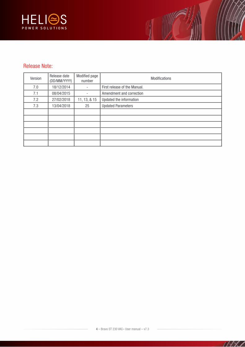
Release Note:
VersionRelease date (DD/MM/YYYY)
Modified page number
Modifications
7.0 18/12/2014 - First release of the Manual.
7.1 08/04/2015 - Amendment and correction
7.2 27/02/2018 11, 13, & 15 Updated the information
7.3 13/04/2018 25 Updated Parameters
4 – Bravo ST 230 VAC– User manual – v7.3

1. CE+T at a glanceCE+T Power designs, manufactures and markets a range of products for industrial operators with mission critical applications, who are not satisfied with existing AC backup systems performances, and related maintenance costs.
Our product is an innovative AC backup solution that unlike most used UPS’s
Maximizes the operator’s applications uptime;
Operates with lowest OPEX;
Provides best protection to disturbances;
Optimizes footprint.
Our systems are:
Modular
Truly redundant
Highly efficient
Maintenance free
Battery friendly
CE+T puts 60+ years expertise in power conversion together with worldwide presence to provide customized solutions and extended service 24/7 - 365
5 – Bravo ST 230 VAC– User manual – v7.3
CE+T at a glance

2. Abbreviations TSI Twin Sine Innovation
EPC Enhanced Power Conversion
REG Regular
DSP Digital Signal Processor
AC Alternating current
DC Direct current
ESD Electro Static Discharge
MET Main Earth Terminal
MBP Manual By-pass
TCP/IP Transmission Control Protocol/Internet Protocol
USB Universal Serial Bus
PE Protective Earth (also called Main Protective Conductor)
N Neutral
PCB Printed Circuit Board
TRS True Redundant Structure
MCB Miniature Circuit Breaker
MCCB Molded Case Circuit Breaker
CB Circuit Breaker
6 – Bravo ST 230 VAC– User manual – v7.3
Abbreviations

3. Warranty and Safety Conditions*
WARNING:
The electronics in the power supply system are designed for indoor, clean environment.
When installed in dusty and/or corrosive environment, outdoor or indoor, it is important to :
Install an appropriate filter on the enclosure door, or on the room’s air control system
Keep the enclosure door closed during operation
Replace the filters on a regular basis.
Important Safety Instructions and Save these Instructions.
The inverter system/rack can reach hazardous leakage currents. Earthing must be carried out prior energizing the system. Earthing shall be made according to local regulations.
Prior to any work conducted to a system/unit make sure that AC input voltage and DC input voltage is disconnected.
CAUTION – Risk of electric shock. Capacitors store hazardous energy. Do not remove cover until 5 minutes after disconnecting all sources of supply.
CAUTION – Risk of electric shock. This Inverter / UPS receives power from more than one source. Disconnection of the AC source and DC source is required to de-energize this unit before servicing.
Maximum operating ambient temperature is 40º C (104º F).
AC and DC circuits shall be terminated with no voltage / power applied.
Some components and terminals carry high voltage during operation. Contact may result in fatal injury.
Warning labels must not be removed.
Never wear metallic objects such as rings, watches, bracelets during installation, service and maintenance of the product.
Insulated tools must be used at all times when working with live systems.
When handling the system/units pay attention to sharp edges.
ESD Strap must be worn when handling PCBs and open units.
The inverter system/rack is not supplied with internal disconnect devises on input nor output.
The inverter rack is a dual input power supply. The complete system shall be wired in a way that both input and output leads can be made powerless in a single action.
REG systems can be seen as independent power sources. To comply with local and international safety standards N (output) and PE shall be bonded.
EPC system that have no AC input wired and connected to comply with local and international safety standards N (output) and PE shall be bonded. The bonded between N output and L must be removed once the AC input is being connected.
The safety standard IEC/EN62040-1-1 requires that, in case of output short circuit, the inverter must disconnect in maximum 5 seconds. However, if the parameter is set at a value > 5 seconds, an external protection must be provided in order that the short circuit protection operates within 5 seconds. Default setting is 60s.
The equipment must be installed and commissioned by skilled technicians according to instructions in this manual.
* These instructions are valid for most CE+T Products/Systems. Some points might however not be valid for the product described in this manual
7 – Bravo ST 230 VAC– User manual – v7.3
Warranty and Safety Conditions

Local regulations must be adhered.
The manufacturer declines all responsibilities if equipment is not- installed according to -instructions herein -by skilled technician -according to local safety regulation.
Warranty does not apply if the product is not installed, used and handled according to the instructions in the manuals.
CE+T cannot be held responsible for disposal of the Inverter system and therefore the customer must segregate and dispose the materials which are potentially harmful to the environment, in accordance with the local regulations in force in the country of installation.
If the equipment is dismantled, to dispose of the products it consists of, you must stick to the local regulations in force in the country of destination and in any case avoid causing any kind of pollution.
System is designed for installation in an IP20 or IP21 environment. When installed in a dusty or humid environment, appropriate measures (air filtering …) must be taken.
3.1 Handling The cabinet shall not be lifted using lifting eyes.
Remove weight from the cabinet by unplugging the inverters. Mark inverters clearly with shelf and position for correct. This is especially important in three phase configurations.
Empty inverter positions must not be left open. Replace with module or cover.
3.2 Surge and transientsThe mains (AC) supply of the modular inverter system shall be fitted with suitable Lightning surge suppression and Transient voltage surge suppression for the application at hand. Manufacturer’s recommendations of installation shall be adhered. It is advisory to select device with alarm relay for function failure.
Indoor sites are considered to have a working lightning surge suppression device in service.
Indoor sites Min Class II.
Outdoor sites Min Class I + Class II or combined Class I+II.
3.3 Other Isolation test must not be performed without instructions from the manufacturer.
To download the latest documentation and software, please visit our website at www.cet-power.com.
8 – Bravo ST 230 VAC– User manual – v7.3
Warranty and Safety Conditions

9 – Bravo ST 230 VAC– User manual – v7.3
TSI TECHNOLOGY
4. TSI TECHNOLOGY 1
Inverter modules carrying the TSI logo and the EPC mark are triple port converters (AC in, DC in, AC out). Sinusoidal output is converted from Mains or/and DC.
The block diagram here below gives an explicit description of the topology and operation.
BOOST
DSP
T2S
EMIFILTER
EMIFILTER
EMIFILTER
UserInterface
RedundantCommuication
Bus
L
N
L’
N’
-
+
Local Signaling
The module is built around the following sub-converters
AC to DC at input
DC to DC at input
DC to AC at output
The energy can flow either from the AC source or the DC source under the control of the local DSP controller. Thanks to internal energy buffering, the output sine wave is constant and disturbance free regardless of the active source.
The BOOST functionality multiplies the nominal current for a period of 20ms(max) in the event of down stream current surge. The upstream breakers do not have to be oversized to prevent tripping. After the boost has been activated or if the AC input is not present the overload capacity is 150% for 15 seconds regardless of the source currently used.
The TSI works according to True Redundant Structure (TRS) that features decentralized and independent logic, redundant communication bus and three internal levels of disconnection to isolate a module after internal failure.
The functionality is included in every inverter module. Running them in parallel provides a modular system with, no single point of failure, always conditioned output, high system efficiency and 0ms source transfer time.
1 | Information and data given in this chapter intend to for an overview on the technology. Detailed features and parameters for each individual module type of the range may differ and should be referred in the dedicated data sheet.

10 – Bravo ST 230 VAC– User manual – v7.3
TSI TECHNOLOGY
4.1 On-line ModeDC is the primary source of supply whilst Mains (AC) works as the secondary source of supply. Switching time between DC input and AC input is 0ms (source transfer).The power delivered by the DC source (usually a battery , but it could be any other type of DC generator) is converted to provide regulated and transient free power to the load. In case of short circuit at the load side, the boost is automatically, timely and energized for a specific duration to trip downstream protective devices.
4.2 Safe modeSafe mode uses DC as primary source of supply while Mains (AC) is in standby.
Mains (AC) is normally disconnected through internal inlet relay and is only connected when down stream clearance is required (boost) or if DC is unavailable.
The transfer between DC and AC results in typical transfer time of 10ms.
Typically the safe mode is used in extremely harshed environments such as railways. Under such conditions it provides extra isolation against disturbances carried by the Mains.
4.3 EPC-modeMains input (AC) is the primary source whilst DC works as backup.
The TSI is designed to operate on Mains on permanent basis and to deliver output voltage conditioned with low THD.
There is no physical difference on the output sine wave whether the source is AC (or) DC. If the Mains is out of tolerance or goes down, the converter seamlessly switches to DC and the converter operates in “Back-up mode” (Switching time back and forth is 0 ms).
As soon as the Mains returns in to valid range, the EPC mode is automatically resumed.
The EPC mode offers higher efficiency (up to 96% depending on the model) without compromising the purity of the output sine wave.
NOTICE: REG modules:
Inverter modules carrying the TSI logo together with REG mark are modules working only with DC input . Sinusoidal output is converted from DC and the module operates as a traditional inverter. EPC mode and the boost are not available with REG modules.
4.4 Mix Mode & Walk-in-modeUnder some circumstances DC and AC source can be combined. The sequence is defined by a user selectable set of parameters, start, control and exit are fully automatic .
A specific example of Mix-mode is the Walk-in mode where the transfer from DC source to AC source is ramped up within a fix and adjustable period of time.
Setting for Walk -in -Mode and Mix Mode can be made through the T2S supervisor configuration file. See section10, page 26 for more information on T2S supervisor.
11 – Bravo ST 230 VAC– User manual – v7.3
TSI TECHNOLOGY
4.5 By Pass ModeThe automatic by pass is engaged in case of following condition
AC input is present and 1 BRAVO TSI Module failure if no redundancy configured OR only one module installed OR
AC input is present and 2 BRAVO TSI module failure if one module redundant has been configured.
The automatic by pass IS NOT AVAILABLE if:
No AC input is present
AC output LOAD exceed 5 kVA

5. DescriptionBravo ST has been designed to give quality power, ease of use, and reliability. It provides up to 4000 watts (Bravo ST 5 KVA) or up to 2000 watts (Bravo ST 2.5 KVA).
In normal operation:
AC input present the TSI module will operate in EPC mode.
AC input fail the TSI module will switch to DC (battery) and continue to feed the load.
DC input fail the system operate on AC input.
TSI module fail (N+1):
If N+1 configuration selected the second module will continue to feed the load.
If the second module fail the system will switch to AC through the automatic by pass to allow module replacement.
TSI module fail (N no redundancy):
If one module fail the BRAVO ST will switch to AC through the automatic by pass to allow module replacement.
All part of the BRAVO ST (Inverter modules and by pass module) are hot swappable without shut down of the AC output.
Warning:
If all modules fails and AC input not present, the system will stop to prevent “backfeed” protection upstream.
12 – Bravo ST 230 VAC– User manual – v7.3
Description
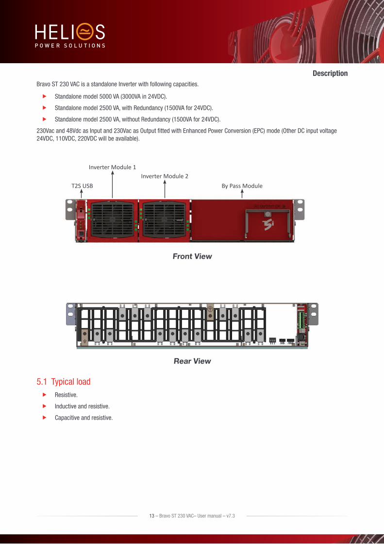
Bravo ST 230 VAC is a standalone Inverter with following capacities.
Standalone model 5000 VA (3000VA in 24VDC).
Standalone model 2500 VA, with Redundancy (1500VA for 24VDC).
Standalone model 2500 VA, without Redundancy (1500VA for 24VDC).
230Vac and 48Vdc as Input and 230Vac as Output fitted with Enhanced Power Conversion (EPC) mode (Other DC input voltage 24VDC, 110VDC, 220VDC will be available).
Inverter Module 1Inverter Module 2
By Pass ModuleT2S USB
Front View
Rear View
5.1 Typical load Resistive.
Inductive and resistive.
Capacitive and resistive.
13 – Bravo ST 230 VAC– User manual – v7.3
Description

14 – Bravo ST 230 VAC– User manual – v7.3
Bravo ST Components
6. Bravo ST Components
6.1 Inverter ModuleBravo: 24 VDC 1500 VA-230 VAC.
48 VDC 2500 VA-230 VAC.
60 VDC 2500 VA-230 VAC.
110 VDC 2500 VA-230 VAC.
220 VDC 2500 VA-230 VAC.
The BRAVO module shall have software version V203 or higher to operate with BRAVO ST.
The TSI Bravo is a 2500VA/2000W converter based on the TSI technology (see section 4). 1500VA/1200W for 24VDC
The TSI inverter modules are hot swappable and hot pluggable. They are featured with self setting capabilities for easy plug-and-play operation.
LED’s on module front plate display the status of converter and output power.
Inverter modules can be combined to build any single or multi-phase structures.
The inverter modules are equipped with soft start.
The fan is equipped with alarm and run time meter. It is field replaceable.
17.13” (D) x 4.02” (W) x 3.46” (H). [435mm (D) x 102mm (W) x 88mm (H)].
11 lbs [5 kg].
6.2 Automatic By-Pass Module 5000 VA By-Pass.
Will automatically connect the load to the commercial grid (if available) when one or both inverter modules are not available.
Transfer time <10ms.
Hot pluggable: can be removed without shutting down the system provided that sufficient inverter modules are present and running.

6.3 Sub-rack The BRAVO ST 230 VAC shelf shall be integrated in min 600mm deep cabinets, 19 Inch / ETSI mounting.
The BRAVO ST 230 VAC shelf houses maximum two (2) inverter modules and one (1) T2S interface. Maximum 5KVA per shelf.
The Bravo ST 230 VAC shelf is designed with individual DC input, common AC input and common AC output.
Optional rear cover can be provided for enhanced safety in cabinet.
18.9” (D) x 19” (W) x 2U (H). [480mm (D) x 19” (W) x 2U (H)].
13 lbs [6 Kg] empty.
15 – Bravo ST 230 VAC– User manual – v7.3
Bravo ST Components

7. Accessories
7.1 T2S-2C InterfaceThe T2S is an interface giving access to the TSI modules that are connected together in any TSI systems.
The T2S doesn’t perform any control or management of the TSI system. It can be removed, replaced or moved to another live system without affecting neither the original TSI system operation nor the target system.
7.1.1 Parameters setting
The T2S interface is featured with a USB connector at the front. Connected to a laptop, it enables TSI system settings, modules and phase assignments, and other various adjustments to allow TSI best fit with actual site conditions. (Operation of T2S is described in separate manual available on request).
7.1.2 System diagnostic and troubleshooting
The T2S is featured with built-in user interface to allow on-line diagnostic through laptop.
Installers and maintenance technicians should always carry proper laptop to access/reconfigure the system on site.
7.1.3 On-the-fly monitoring
The T2S is featured with
3 outgoing alarms contacts.
2 digital inputs.
MOD bus.
CAN bus (optional).
Alarm monitoring.
Record the latest 200 events. FIFO.
7.2 Surge ArrestersThe mains (AC) supply of the modular inverter system shall be fitted with suitable Lightning surge suppression and Transient voltage surge suppression for the application at hand. Manufacturer’s recommendations of installation shall be adhered. It is advisory to select a device with an alarm relay for function failure.
Surge arrestor(optional) is installed in the system.
Indoor sites are considered to have a working lightning surge suppression device in service.
Indoor sites Min Class II.
Outdoor sites Min Class I + Class II or combined Class I+II.
16 – Bravo ST 230 VAC– User manual – v7.3
Accessories
8. Bravo ST Shelves Installation
8.1 Unpacking the systemBRAVO ST is packed in a wooden box.
Modules are packed seperately. They are normally marked to be replaced in the right slot
Module packing material shall be taken apart and stored in case of return under warranty. Unproper packing may void the warranty.
The packing material of the TSI system is recyclable.
8.2 Mechanical Installation Sub-rack is preferable mechanically fixated without modules.
T2S-2U can be left in the sub-rack.
Min two (2) fixing screws per side of the sub rack.
Fixing holes for Inch and ETSI mounting frames.
System is designed for installation in an IP20 or IP21 environment. When installed in a dusty or humid environment, appropriate measures (air filtering …) must be taken.
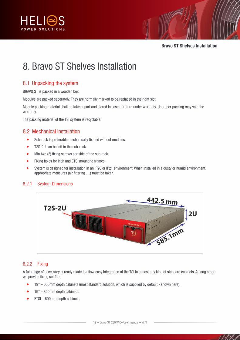
8.2.1 System Dimensions
8.2.2 Fixing
A full range of accessory is ready made to allow easy integration of the TSI in almost any kind of standard cabinets. Among other we provide fixing set for:
19” – 600mm depth cabinets (most standard solution, which is supplied by default - shown here).
19” – 800mm depth cabinets.
ETSI – 600mm depth cabinets.
17 – Bravo ST 230 VAC– User manual – v7.3
Bravo ST Shelves Installation
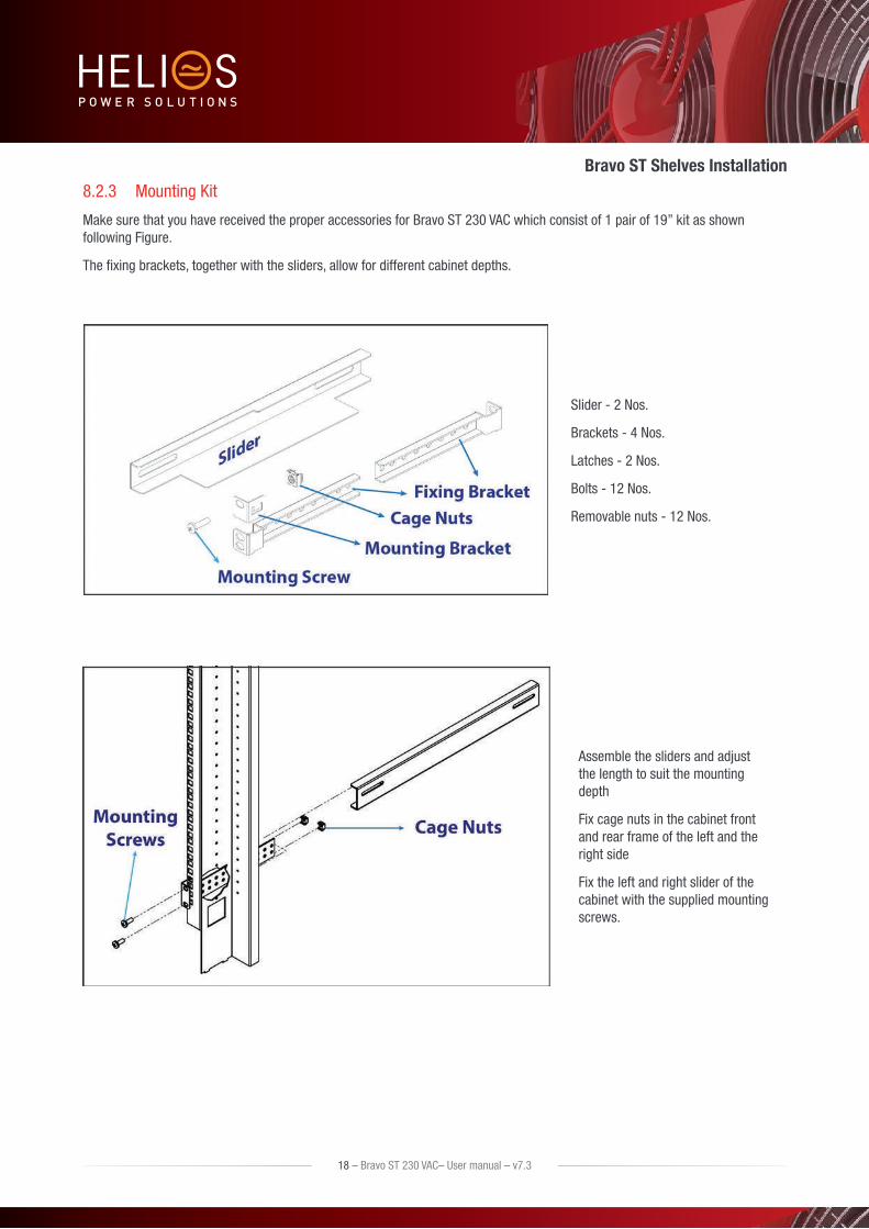
8.2.3 Mounting Kit
Make sure that you have received the proper accessories for Bravo ST 230 VAC which consist of 1 pair of 19” kit as shown following Figure.
The fixing brackets, together with the sliders, allow for different cabinet depths.
Slider - 2 Nos.
Brackets - 4 Nos.
Latches - 2 Nos.
Bolts - 12 Nos.
Removable nuts - 12 Nos.
Assemble the sliders and adjust the length to suit the mounting depth
Fix cage nuts in the cabinet front and rear frame of the left and the right side
Fix the left and right slider of the cabinet with the supplied mounting screws.
18 – Bravo ST 230 VAC– User manual – v7.3
Bravo ST Shelves Installation
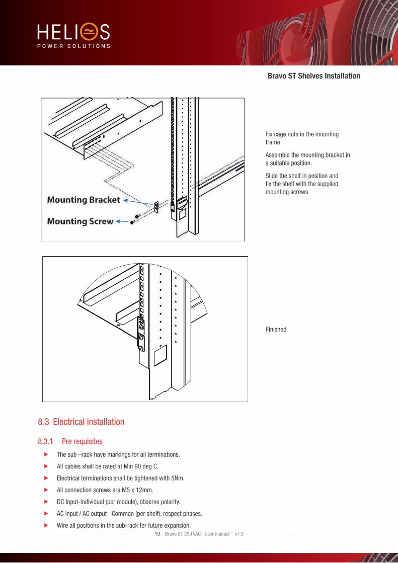
Fix cage nuts in the mounting frame
Assemble the mounting bracket in a suitable position.
Slide the shelf in position and fix the shelf with the supplied mounting screws
Finished
8.3 Electrical installation
8.3.1 Pre requisites
The sub –rack have markings for all terminations.
All cables shall be rated at Min 90 deg C.
Electrical terminations shall be tightened with 5Nm.
All connection screws are M5 x 12mm.
DC Input-Individual (per module), observe polarity.
AC Input / AC output –Common (per shelf), respect phases.
Wire all positions in the sub-rack for future expansion.19 – Bravo ST 230 VAC– User manual – v7.3
Bravo ST Shelves Installation
Input AC / Output AC / Input DC / Signal cables shall be separated
Cable crossings shall be done in 90 deg angles.
It is recommended to install appropriate breaker at AC input and place a warning label near the breaker stating message as “ISOLATE UNINTERRUPTIBLE POWER SUPPLY (UPS) BEFORE WORKING ON THIS CIRCUIT”.
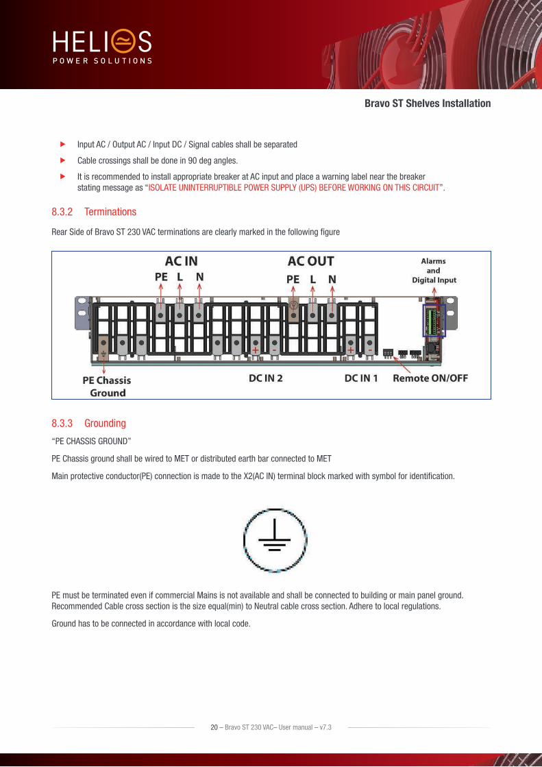
8.3.2 Terminations
Rear Side of Bravo ST 230 VAC terminations are clearly marked in the following figure
8.3.3 Grounding
“PE CHASSIS GROUND”
PE Chassis ground shall be wired to MET or distributed earth bar connected to MET
Main protective conductor(PE) connection is made to the X2(AC IN) terminal block marked with symbol for identification.
PE must be terminated even if commercial Mains is not available and shall be connected to building or main panel ground. Recommended Cable cross section is the size equal(min) to Neutral cable cross section. Adhere to local regulations.
Ground has to be connected in accordance with local code.
20 – Bravo ST 230 VAC– User manual – v7.3
Bravo ST Shelves Installation

8.3.4 DC Input
Model CB per inverter module Cable, min Connector Torque
24 VDC & 48 VDC 63 A 2 x 4 AWG ( 16 mm2)
M5 5 Nm60 VDC 50 A 2 x 6 AWG ( 10 mm2)
110 VDC 25 A 2 x 10 AWG ( 4 mm2)
220 VDC 16 A 2 x 12 AWG ( 2.5 mm2)
8.3.5 AC Input (AC Input protection mandatory)
Model CB per shelf Cable, min Connector Torque
230 VAC (5 KVA) 2p 25 A 3 x 10 AWG ( 4 mm2)M5 5 Nm
230 VAC (2.5 KVA) 2p 16 A 3 x 12 AWG ( 2.5 mm2)
8.3.6 AC output
Model Cable, min Connector Torque
230 VAC (5 KVA) 3 x 10 AWG ( 4 mm2)M5 5 Nm
230 VAC (2.5 KVA) 3 x 12 AWG ( 2.5 mm2)
8.3.7 Signalling
21 – Bravo ST 230 VAC– User manual – v7.3
Bravo ST Shelves Installation

Relay characteristics (Selectable, Major, Minor)
Switching power 60W
Rating 2A at 30VDC / 1A at 60VDC
Max wire size 1mm2
Digital input characteristics (Digital In 1 / 2)
Signal voltage +5VDC (galvanic insulated)
Max wire size 1mm2
8.3.7.1 Remote ON/OFF
Note: The system is by default equipped with a connection between pin 3 and 2. If remote ON/OFF is not used the strap shall remain. Should the remote ON/OFF be used the strap must be replaced with a changeover contact or emergency button.
* To remove when external remote is used, must be present if not used.
The remote ON/OFF switch the output AC OFF.
Input AC and input DC is not affected by the remote ON/OFF.
The remote ON/OFF requires changeover contacts, one input opens as the other close. If both transitions are not picked up the status is not changed.
Digital input characteristics (Remote On/Off) - Signal voltage +5 VDC (galvanically insulated) - Max wire size 17 AWG (1mm2)
Functional table for remote ON/OFF function
# Pin 1-3 Pin 2-3 Status Indication
1 Open Open Normal operation All (Green)
2 Closed Open OFF AC output (OFF) AC Input (Green) DC Input (Green)
3 Open Closed Normal operation All (Green)
4 Closed Closed Normal operation All (Green)
Warning: If remote ON/OFF not used, pin 2 and 3 MUST be bridged together!
3
2
1
Common
ON
OFF
22 – Bravo ST 230 VAC– User manual – v7.3
Bravo ST Shelves Installation
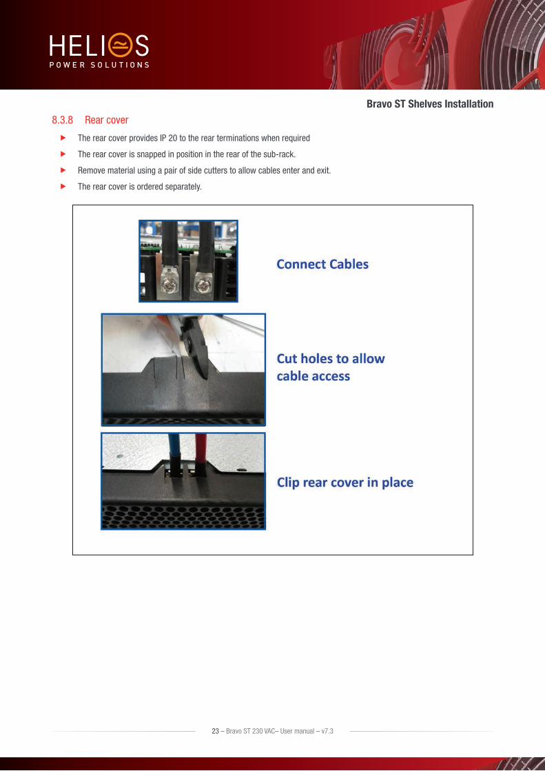
8.3.8 Rear cover
The rear cover provides IP 20 to the rear terminations when required
The rear cover is snapped in position in the rear of the sub-rack.
Remove material using a pair of side cutters to allow cables enter and exit.
The rear cover is ordered separately.
23 – Bravo ST 230 VAC– User manual – v7.3
Bravo ST Shelves Installation

9. Human-Machine Interface
9.1 Inverter module (Requires firmware V203 or higher)
=~
==
=~
AC out
DC in
AC in
Inverter Status Output Power Status
Inverter Status LED Description Remedial action
OFF No input power or forced stop Check environment
Permanent green Operation
Blinking greenConverter OK but working conditions are not fulfilled to operate properly
Blinking green/orange alternativelyRecovery mode after boost (10 In short circuit condition)
Permanent orange Starting mode
Blinking orange Modules cannot startCheck T2S configuration or Module with wrong firmware. Need firmware V203 or higher.
Blinking red Recoverable fault
Permanent red Non recoverable fault Send module back for repair
Output Power (redundancy not counted)
<5%5% to 40%
40 to 70%
80 to 95%
100%100% = overload
Output Power (redundancy not counted)
× × ×
Status output power LED× ×
×
1B 1P 2P 2P 3P 3B Behaviour (B = blinking – P permanent )
24 – Bravo ST 230 VAC– User manual – v7.3
Human-Machine Interface

9.2 T2S T2S has two new parameters.
Parameter Parameter Name Values Description
420 ST Module Number 0, 1 or 2 Define the total number of BRAVO modules in the configuration.
(Including Redundancy module)
421 ST Module Redundancy 0 or 1 Define the number of Redundancy module in the configuration.
Note: The BRAVO module V203 or higher those parameters appear automatically and T2S is pre configured in factory.
If you change T2S you must be sure to configure the parameter correctly prior to insert in the BRAVO ST
Alarm indication on T2S (Urgent / Non Urgent / Configurable) - Green: No alarm - Red: Alarm - Flashing Exchanging information with inverters (only Configurable alarm)
Outgoing alarm relay delay - Urgent 60 seconds delay - Non urgent 30 second delay
Parameter setting via Laptop.
Factory default according to list of set values.
The following BRAVO ST configuration parameters are :
1. BRAVO ST - 5KVA –No redundancy
;420; ;ST Module Number ; ;2; ;;
;421; ;ST Module Redundancy ; ;0; ;;
2. BRAVO ST - 2.5 KVA –No redundancy
;420; ;ST Module Number ; ;1; ;;
;421; ;ST Module Redundancy ; ;0; ;;
3. BRAVO ST - 2.5 KVA –1+1 redundancy
;420; ;ST Module Number ; ;2; ;;
;421; ;ST Module Redundancy ; ;1; ;;
Major Alarm
Minor Alarm
User selectable Alarm
USB port
25 – Bravo ST 230 VAC– User manual – v7.3
Human-Machine Interface

10. System set upBravo ST 230 VAC System is delivered with default set of parameters referred as factory settings.
Upon various site operating conditions or Site Manager requirements some parameters might have to be adjusted.
Refer to “TSI T2S 120VAC User Manual Vx_x” for detailed description of system status reading and changing as well as parameter adjustment.
Parameter set up requires Hyper terminal installed on laptop
USB cable type A to B (not included)
T2S driver “CET_T2S.inf” installed on laptop.
Available for download: - On my.CET for direct customers, in the “Document” section. - At the following URL for everyone else: http://www.cet-power.com/uploads/Driver_T2S/Driver_T2S_for_Windows_and_hyperterminal.zip.
Read T2S manual for detailed setup.
10.1 Communication Setting Bits per second 115200
Data bits 8
Parity None
Stop bits 1
Flow control None
Remark: Refer to document XXXX for detailed system setting and operation.
26 – Bravo ST 230 VAC– User manual – v7.3
System set up

10.2 Menu accessRoot Menu
1 > System configuration
0 > Return to previous menu
1 > Send config file to T2S
2 > Read config file from T2S
3 > Restore default settings (no more available since version 2.5)
4 > Restore factory settings (no more available since version 2.5)
2 > System information’s selection
0 > Return to previous menu
1 > Module information’s 0 > Return to previous menu 1 > Variables set 1 2 > Variables set 2 3 > Variables set 3 4 > Variables set 4 + > Next page - > Previous page
2 > Phase information 0 > Return to previous menu 1 > Variables set 1 2 > Variables set 2 3 > Variables set 3
3 > Groups information 0 > Return to previous menu 1 > Display AC group information 2 > Display DC group information
4 > Alarms information 0 > Return to previous menu 1-1 > Page selection
5 > History of the log display 0 > Return to previous menu 1-14 > Page number selection 16 > Clear log 17 > Save log to a file
6 > Module errors information
0 > Return to preceding menu 1-32 > Detailed Modules errors
3 > System actions selection 0 > Return to previous menu
1 > System actions 0 > Return to index 1 > Turn ON system 2 > Turn OFF system 3 > Change Date and time setting
2 > Inverter Module action 0 > Return to previous menu 1-4 > Page number selection 5 > Identify selected Module 6 > Turn ON selected Module 7 > Turn OFF selected Module 8 > Change address of sel. Module 9 > Change phase of selected Module 10 > Automatic address assignment 11 > Change DC group of selected Module 12 > Change AC group of sel. Module 13 > Notify changed fan of sel. Module
+ > Increment selector - > Decrement selector
3 > T2s actions 0 > Return to index 1 > Force refresh of configuration texts and constants 2 > Force refresh of events description texts
4 > Security Access
0 > Return to index
1 > Enable Password protection
27 – Bravo ST 230 VAC– User manual – v7.3
System set up

11. Inserting/removing/replacing modules
11.1 TSI Inverter The TSI inverter module is hot swappable. BRAVO ST operate with module having firmaware V203 or higher.
When a new module is inserted in a live system it automatically takes the working set of parameters.
When a new module is inserted in a live system it is automatically assigned to the next available address.
While swapping the modules, power to load will be vary depending upon the models and are listed below.
Note:
Before swapping Inverter module, make sure the commercial grid is available to prevent any shut down of the AC output voltage.
The commercial grid shall be within the limit in voltage (195 Vac to 250 Vac) and frequency between 47,5 Hz to 52,5 Hz for 50Hz nominal and 57,5Hz to 62,5 Hz for 60Hz nominal.
If the load is supplied by “relay box” and the AC commercial input is not within the range (voltage and frequency) please DO NOT INSTALL NEW module. Risk of shutdown of the LOAD is present !!!
Module inserted in BRAVO ST with firmware below V203 cannot be used. They will not operate properly and will heat up abnormally.
BRAVO ST 5000VA (3000VA in 24V) - 2 Inverter Modules present + By Pass Module
• Any one or both Inverter Modules can be removed or added.
• When, either one or both Inverter Modules are replaced the AC output will be transferred to the AC commercial grid through the By-Pass Module.
Bravo ST 2500 VA with Redundancy (2 Inverter Modules present + By Pass Module)
• Any one or both Inverter Modules can be removed or added.
• If one Inverter Module is removed, the load is supplied from the redundant Inverter Module.
• If both Modules are removed, the load will automatically connect to grid through the By Pass Module.
Bravo ST 2500 VA without Redundancy (One Module present + By Pass Module)
• The Inverter Module can be removed or added.
• When the Module is removed, the load will automatically connect to grid through the By Pass Module.
28 – Bravo ST 230 VAC– User manual – v7.3
Inserting/removing/replacing modules

11.1.1 Module Removal
Notice: When one or several inverter modules is/are removed, live parts become accessible. Replace module with blinds without delay.
Inverter module is not switched off when opening the handle. The handle only hooks the module to the shelf.
Use a screw driver to release the latch of the handle.
Open the handle and Pull the module out.
Replace with new module or blind unit.
A) Use screwdriver to release the latch B) open the cover completely C) Use the cover as a handle to remove the module
11.1.2 Inserting
Check module compatibility (DC Voltage!)
Use a screw driver to release the latch of the handle.
Open the handle and Push firmly until the unit is properly connected.
Close the cover and latch in position.
A) Slide the module in B) Push firmly till the connection is properly engaged
C) Close the cover and latch the module in place if too hard redo step B
Once the module is properly insert and locked it will restart automatically and the load will be transferred from the by-pass module to the inverter. The sequence might take 10 to 40 seconds.
29 – Bravo ST 230 VAC– User manual – v7.3
Inserting/removing/replacing modules

11.2 TSI By-Pass Module Replacement
11.2.1 Removal
Note : Before replacing the By-Pass Module please make sure the inverter module are in operation and both AC input and DC input source are available.
11.2.2 Inserting
30 – Bravo ST 230 VAC– User manual – v7.3
Inserting/removing/replacing modules

11.3 T2S
11.3.1 Removal
Use a small screw driver to release the latch keeping the T2S in position.
Pull the T2S out.
11.3.2 Inserting
Push the T2S firmly in place until the latch snaps in position.
11.4 Fan replacementThe FAN life is approx 60.000 (Sixty Thousand) hours. The inverter modules have fan runtime meters and fan failure alarm. Fan failure can result from failing fan or driver circuit.
Let the module rest at least 5 minutes prior to initiating work.
The inverter front must be removed. Use a blunt tool to depress the latches on the module side fixing the front to the module.
Remove the fan and unplug the supply cord.
Replace with new fan and connect supply cord
Replace front, make sure that the front latch properly.
Plug in
Check fan for operation
Access T2S and reset the fan run time alarm from within the action menu.
Once the FAN is replaced and module installed back in your system, You will need to clear the FAN alarm of the module. This can be done through the T2S menu 3 Action then 2 inverter action then 13 Notify change FAN.
Refer to T2S manual for more details.
31 – Bravo ST 230 VAC– User manual – v7.3
Inserting/removing/replacing modules

Final check Make sure that the sub-rack/cabinet is properly fixed to the cabinet/floor.
Make sure that the sub-rack/cabinet is connected to Ground.
Make sure that all DC and AC input breakers are switched OFF.
Make sure that all cables are according to recommendations and local regulations.
Make sure that all cables are strained relived.
Make sure that all breakers are according to recommendation and local regulations.
Make sure that DC polarity is according to marking.
Re tighten all electrical terminations.
Make sure that no inverter/controller positions are left open.
Cover empty inverter positions with blanks.
Make sure that the Remote ON/OFF is appropriately wired according to local regulations.
Make sure that the point of AC supply meets local regulations.
32 – Bravo ST 230 VAC– User manual – v7.3
Inserting/removing/replacing modules

12. CommissioningThe DC breaker is a protection device. Modules are plugged in a system and DC breaker is then engaged. Please make sure the corresponding DC breaker is engaged in the ON position. Failure to observe this rules will result not to have all module operating when running on DC and have module failure when AC input recover from fault condition.
Installation and commissioning must be done and conducted by trained people fully authorized to act on installation.
It is prohibited to perform any isolation test without instruction from manufacturer.
Equipments are not covered by warranty if procedures are not respected.
33 – Bravo ST 230 VAC– User manual – v7.3
Commissioning
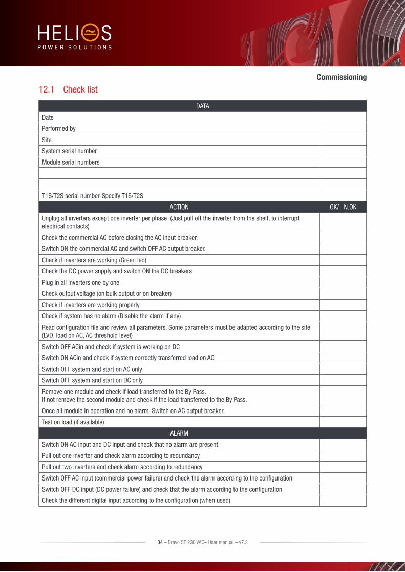
12.1 Check list
DATA
Date
Performed by
Site
System serial number
Module serial numbers
T1S/T2S serial number-Specify T1S/T2S
ACTION OK/ N.OK
Unplug all inverters except one inverter per phase (Just pull off the inverter from the shelf, to interrupt electrical contacts)
Check the commercial AC before closing the AC input breaker.
Switch ON the commercial AC and switch OFF AC output breaker.
Check if inverters are working (Green led)
Check the DC power supply and switch ON the DC breakers
Plug in all inverters one by one
Check output voltage (on bulk output or on breaker)
Check if inverters are working properly
Check if system has no alarm (Disable the alarm if any)
Read configuration file and review all parameters. Some parameters must be adapted according to the site (LVD, load on AC, AC threshold level)
Switch OFF ACin and check if system is working on DC
Switch ON ACin and check if system correctly transferred load on AC
Switch OFF system and start on AC only
Switch OFF system and start on DC only
Remove one module and check if load transferred to the By Pass. If not remove the second module and check if the load transferred to the By Pass.
Once all module in operation and no alarm. Switch on AC output breaker.
Test on load (if available)
ALARM
Switch ON AC input and DC input and check that no alarm are present
Pull out one inverter and check alarm according to redundancy
Pull out two inverters and check alarm according to redundancy
Switch OFF AC input (commercial power failure) and check the alarm according to the configuration
Switch OFF DC input (DC power failure) and check that the alarm according to the configuration
Check the different digital input according to the configuration (when used)
34 – Bravo ST 230 VAC– User manual – v7.3
Commissioning

13. Trouble Shooting and Defective Situations Fixing
13.1 Trouble ShootingInverter module does not power up: Check AC input present and in range (AC breakers)
Check DC input present and in range (DC breakers)
Check that the inverter is properly inserted
Remove inverter to verify that slot is not damaged, check connectors
Check that module(s) is (are) in OFF state
Check for loose terminations
Inverter system does not start: Check that T2S is present and properly inserted
Check remote ON/OFF terminal
Check the configuration and setting
Check threshold level
Inverter only run on AC or DC: Check AC input present and in range (AC breakers)
Check DC input present and in range (DC breakers)
Check the configuration and setting
Check threshold level(s)
No output power: Check output breaker
All OK but I have alarm: Check configuration file and correct No of modules
Download/clear log file
No output alarm: Mind the default time delay (UA: 60s, NUA: 30s)
Check configuration file
No information on CanDis: Check that T2S is present and properly inserted
Check that the RJ45 cable is connected between T2S shelf and CanDis shelf
No value on TCP/IP: Check that the RJ45 cable is connected between T2S shelf and CanDis shelf
Wait approx 2 minutes to allow the system to collect serial data.
35 – Bravo ST 230 VAC– User manual – v7.3
Trouble Shooting and Defective Situations Fixing

13.2 Defective modulesUnless input power is down all LEDs on each module should be green (see section 9, page 24). No light, orange light , red or flashing light are abnormal conditions. Refer to section 10.2, page 27 to collect and record module information. If no fix can be found, replace module.
13.2.1 Replacing modules
Refer to section 11, page 28 to remove and re-insert modules.
13.2.2 Return defective T2S interface
A T2S totally dark (indication area) or that cannot interface with your laptop are evidence of failure. Proceed as per section 13.2.4, page 36.
13.2.3 Return defective shelf
The shelf is passive. Failure is unlikely to happen. In turn defective situation are barely always visible. After depose proceed as per section 13.2.4, page 36.
13.2.4 Return defective modules
A repair request should follow the regular logistics chain: End-user => Distributor => CE+T Power.
Before returning a defective product, a RMA number must be requested through the http://my.cet-power.com extranet. Repair registering guidelines may be requested by email at [email protected].
The RMA number should be mentioned on all shipping documents related to the repair.
Be aware that products shipped back to CE+T Power without being registered first will not be treated with high priority!
Information on failure occurrence as well as module status given through Menu 2-1 shall be attached to defective unit return package or recorded in RMA.
36 – Bravo ST 230 VAC– User manual – v7.3

14. ServiceFor Service
Check Service Level Agreement (SLA) of your vendor. Most of the time they provide assistance on call with integrated service. If such SLA is in place, you must call their assistance first.
If your vendor doesn’t provide such assistance (*) you may call CE+T directly. Toll free Number 1(855) 669 - 4627 (**)
Service is available from 8:00 A.M. to 10:00 P.M. EST, Monday through Friday, except closing periods for holidays or inclement weather.
Major Incidents and Emergency conditions can be invoked for immediate handling of same number or by dropping a mail on [email protected] (***)
(*) CE+T will redirect your call to your vendor if he has such SLA in place.
(**) Valid in USA and Canada only.
(***) Messages that are not Major Incident or Emergency will be served at the next scheduled working day.
37 – Bravo ST 230 VAC– User manual – v7.3
Service

15. Maintenance TaskAs maintenance will be performed on live system, all tasks should be performed only by trained personnel with sufficient acknowledge on TSI product.
Tasks :
Identify the site, customer, rack number, product type.
Download and save configuration file for back up.
Check configuration file to be in accordance with operational site conditions.
Read and save log file for back up.
Check and analyze log file, and if alarm are present.
Replace dust filter if present. Filter is mandatory in dusty environment.
Check module temperature and log value. If internal temperature is higher then previous year, it should be interesting analyze if it is due an increasing load or dust effect. It is common to have a delta of 15°C by 30% of load between the ambient and the internal temperature. If temperature increase due internal dust built up clean the TSI with vacuum cleaner and/or soft compressed air.
Clean cabinet (vacuum cleaner or dry cloth)
Control the inverter mapping (AC Group, DC Group, Address)
Check load level and record the rate value (print in word document the 4 screen modules information for the 32 modules, the 3 screen for the phases value and the 2 screens for the group AC and DC value)
Change the configuration file for AC and DC mix mode to check that all TSI work on both power supply
Check alarm operation (e.g., redundancy lost, mains failure, DC failure) on dry contact and through SNMP system or web interface.
Switch OFF AC IN and check alarms.
Check temperature terminal and temperature wiring. If possible use an infrared camera.
Read and record value as wave form, power factor, Crest factor, THD I from power analyzer.
Take cabinet picture
Keep track of report and provide end user with a copy.
Perform a MBP procedure. This task is not really recommended*, but could be demanded by site manager.
* It is not recommended because when you perform a By-pass procedure, generally there is no back up on AC input line, and the load shutdown if mains disappear.
38 – Bravo ST 230 VAC– User manual – v7.3
Maintenance Task
