bray park water treatment plant - tweed.nsw.gov.au
TRANSCRIPT
Tweed Shire Council
Tweed Shire Council is committed to supplying high quality and safe drinking water. Most of Tweed’s water supply is processed at Bray Park Water Treatment Plant which incorporates state of the art membrane technology and has a capacity to treat up to 100 ML of water per day.
Raw water for the Tweed region’s domestic water supply is drawn directly from the Tweed River to the Water Treatment Plant where it is treated to remove sediments and kill bacteria and viruses.
Catchment Area
The area of the Tweed water supply catchment is more than 560 square kilometres. Covering over one third of the entire shire, extending from the Nightcap Ranges in the south to the Border Ranges in the west. For more information refer to Tweed Catchment and Water Quality Fact Sheet.
Bray Park Water Treatment PlantMembrane Ultrafiltration Technology
Key Facts and Figures
• Commissioned in April 2010.• Membrane Ultrafiltration technology.• Capacity to treat up to 100 ML/day with infrastructure to expand to 150 ML/day.• Current annual extraction from the Tweed River is approximately 9,500 to 10,000 ML.• The peak day production was 51.4 ML in 2002• Residential consumption is approximately 60% of total water consumption• In 2008 the average daily residential consumption was 201 litres per person• In 2008 the average annual residential consumption was 73,385 litres per person.
The WTP processes provide a robust multi-barrier approach to the removal of pathogens to ensure the water quality meets the highest drinking water standards.
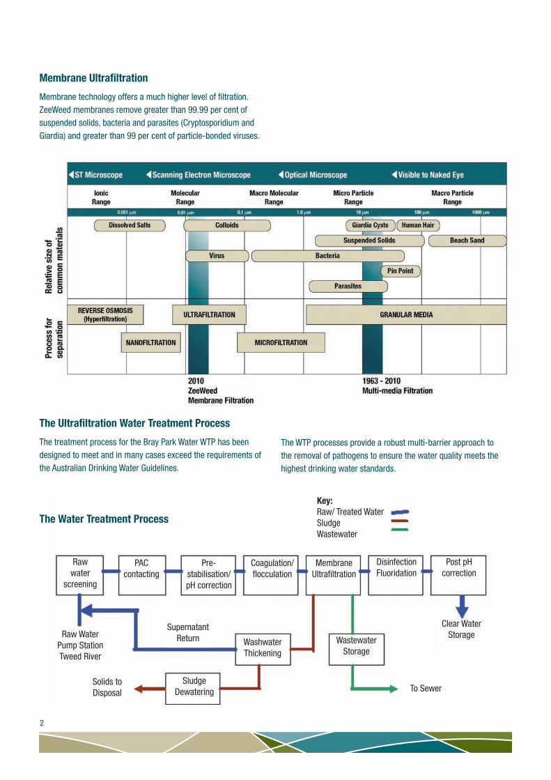
Membrane Ultrafiltration
Membrane technology offers a much higher level of filtration. ZeeWeed membranes remove greater than 99.99 per cent of suspended solids, bacteria and parasites (Cryptosporidium and Giardia) and greater than 99 per cent of particle-bonded viruses.
The Ultrafiltration Water Treatment Process
The treatment process for the Bray Park Water WTP has been designed to meet and in many cases exceed the requirements of the Australian Drinking Water Guidelines.
The Water Treatment Process
2
Rawwater
screening
PAC contacting
Pre-stabilisation/pH correction
Coagulation/flocculation
MembraneUltrafiltration
DisinfectionFluoridation
Post pHcorrection
WashwaterThickening
WastewaterStorage
SludgeDewatering
SupernatantReturnRaw Water
Pump StationTweed River
Clear WaterStorage
Solids toDisposal To Sewer
Key:Raw/ Treated WaterSludgeWastewater

Bray Park Weir
Bray Park Weir
Raw Water Strainers
this process is recycled via the Strainer Pumping Station, to the Washwater Balance Tank.
• Two raw water strainers
• 0.8 mm pore size screen
Flowmeter
An electromagnetic flow meter measures the rate of raw water entering the treatment plant.
Powdered Activated Carbon (Pac) Dosing
The PAC facility mixes water and PAC to make a slurry, which is then added to the raw water to remove organic contaminants such as tastes, odours and toxins associated with blue green algal blooms.
Raw water dosed with PAC enters the PAC Contact Tank. It is important that the PAC is in contact with the raw water for at least 20 minutes to effectively remove the contaminants. To ensure this contact time, the Contact Tank is divided into four compartments so that the water has to move slowly from one compartment to the next before leaving the tank.
PAC is finely ground carbon that has been treated to give it a high porosity and surface area. Organic contaminants in the raw water are adsorbed onto the surfaces of the PAC (adsorb is the process where a particle adheres to the surface of another). The PAC and these organic contaminants are later removed during the Membrane Ultrafiltration Stage. PAC can be made from a variety of carbon-based materials, including wood, coal and coconut shells. At this treatment plant, a wood-based PAC is used to protect the membranes.
• Delivered in 500 kg bags.
• Contact time 20-60 minutes.
• PAC tank volume 1.62 ML, depth 5 m.
Flows from the PAC Tank gravitate to the Membrane Facility.
Raw Water Pump Station
Raw water drawn from the Bray Park Weir passes through the intake screen to remove large objects before being pumped to the treatment plant.
• Intake screens are 50 mm grate size.
• Two pumps with a total capacity of 1250 L/s.
• Distance from pump station to raw water strainers is 1.4 km.
Rising Mains
Two pipes of 750 mm and 1030 mm diameter transfer the raw water from the pump station to the treatment plant.
Raw Water Strainers
Raw water is screened through inline strainers to remove items such as weeds, algae, fish, shrimp and debris. This high level of screening also protects the membrane filters from physical damage.
Screened water is used to intermittently backwash solids that become lodged in the strainers. The backwash is de-watered through an inclined screw driven screen and the solids sent to a waste bin before being transported to landfill. The water from
3

Powdered Activated Carbon (PAC)
PAC Mixing Tank
Lime Solo
Lime dosing facility
Flowmeter and Actuated Control Valve
Flows from the PAC tank gravitate to the Membrane Facility via a flow meter and actuated valve.
An electromagnetic flow meter measures the rate of raw water entering the Membrane Facility. The Actuated Valve is used for controlling the flow rate into the Membrane Facility
Manganese Removal
Potassium Permanganate (KMnO4) is used to oxidise soluble manganese to produce insoluble manganese which can be removed by filtration. The level of manganese in the raw water is measured and sufficient potassium permanganate added to remove the manganese. Dosing prior PAC tank provides sufficient contact time.
Pre-Stabilisation and Ph Correction
Dosing of Lime, Carbon Dioxide and Alum occurs between the PAC tank and Membrane Facility.
Raw water entering the plant after heavy rain can have a low alkalinity, with a pH that is slightly acidic and corrosive to
cement-lined pipes. In addition, the pH of the treated water in the distribution network can move out of range, affecting the effectiveness of the chlorine in disinfection.
To correct this, lime is added as slurry, followed by carbon dioxide gas to both control the water stability and adjust the pH to a suitable level for coagulation. The lime not only increases the alkalinity, but also increases the calcium content in the treated water, making it more stable.
Lime Dosing, CaO
4

Pre-flocculation Tank
Flocculation Tanks
Membrane Ultrafiltration
Flocculation Tanks
Coagulated Alum dosed water flows into a Pre-flocculation Tank which allows the flows entering the tank to distribute along the length of the tank and provide equal flow to all flocculation tanks. This is aided by a baffle wall. Six Flocculation Tanks with mixers are designed to keep the flocs in suspension so they grow to a suitable size that can be filtered out through the Membrane Ultrafiltration Process.
The Membrane Distribution Channel sits between the flocculation tanks and membrane tanks. It allows connection of any Flocculation Tank to any Membrane tank, so if a Flocculation tank is isolated for cleaning, all Membrane tanks can continue to operate. There are 1 mm screens on the inlet to each membrane tank that provide additional protection to the membranes.
The membrane tanks have a baffled plate at the inlet to distribute the flow and prevent damage to the membranes.
• Four Membrane Tanks operate for the 100 ML per day plant, each with a volume of 160,000 L and depth of 3 m.
• Six Membrane Tanks have been built to cater for expansion to a 150 ML per day facility in the future. Currently, the extra two tanks are used for neutralisation of membrane cleaning chemicals and membrane backwashing.
Lime Dosing Facility
• Single bulk lime silo – 50 tonnes storage.
• Typical dose – 15 mg/L.
Carbon Dioxide Dosing Facility
• Single 50 tonne storage vessel.
• Typical dose 20 mg/L.
• Carbon dioxide, CO2 gas is dissolved into side stream
Alum Dosing – Flocculation And Coagulation
Aluminium sulphate, Al2(SO4)3 (commonly called Alum) is introduced to help bind together smaller particles (Coagulation) such as suspended solids, decaying vegetation, micro-organisms and colour-producing compounds, which have not been removed through screening. These bound particles are called ‘flocs’. The Alum is added by side-stream flash mixing (rapid mixing). The flocs grow in size the longer they are allowed to interact with each other (Flocculation).
• Typical Dose – 30 mg/L
Membrane Facility
5

Membrane fibre – A hollow fibre with an external diameter of 1.9 mm and an internal diameter of 0.8 mm.
There are 6.44 million fibres in total.
Membrane module – Each module consists of around 3354 membrane fibres and has a surface area of 40.9 m2.
There are 1920 modules in total.
Membrane Structure Overview
In order to achieve the high flows required at Bray Park through the membrane pores (nominal pore size of 0.04 micrometers), a large surface area of membrane fibre is required. The plant is therefore constructed with a series of membrane building blocks:
Membrane cassette – Each cassette is made up of 60 membrane modules, each slide into place in the cassette (similar to sliding CDs into a CD rack).
There are 32 cassettes in total.
Membrane train – Within each train are eight membrane cassettes. The cassettes are arranged in pairs with each pair connected to a common header pipe.
There are four membrane trains in total.
6
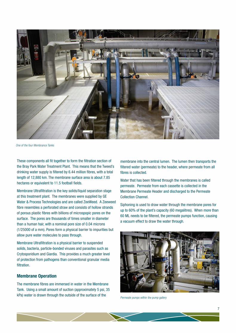
One of the four Membrance Tanks
Permeate pumps within the pump gallery
These components all fit together to form the filtration section of the Bray Park Water Treatment Plant. This means that the Tweed’s drinking water supply is filtered by 6.44 million fibres, with a total length of 12,880 km. The membrane surface area is about 7.85 hectares or equivalent to 11.5 football fields.
Membrane Ultrafiltration is the key solids/liquid separation stage at this treatment plant. The membranes were supplied by GE Water & Process Technologies and are called ZeeWeed. A Zeeweed fibre resembles a perforated straw and consists of hollow strands of porous plastic fibres with billions of microspopic pores on the surface. The pores are thousands of times smaller in diameter than a human hair, with a nominal pore size of 0.04 microns (1/25000 of a mm). Pores form a physical barrier to impurities but allow pure water molecules to pass through.
Membrane Ultrafiltration is a physical barrier to suspended solids, bacteria, particle-bonded viruses and parasites such as Crytosporidium and Giardia. This provides a much greater level of protection from pathogens than conventional granular media filtration.
Membrane Operation
The membrane fibres are immersed in water in the Membrane Tank. Using a small amount of suction (approximately 5 psi, 35 kPa) water is drawn through the outside of the surface of the
membrane into the central lumen. The lumen then transports the filtered water (permeate) to the header, where permeate from all fibres is collected.
Water that has been filtered through the membranes is called permeate. Permeate from each cassette is collected in the Membrane Permeate Header and discharged to the Permeate Collection Channel.
Siphoning is used to draw water through the membrane pores for up to 60% of the plant’s capacity (60 megalitres). When more than 60 ML needs to be filtered, the permeate pumps function, causing a vacuum effect to draw the water through.
7
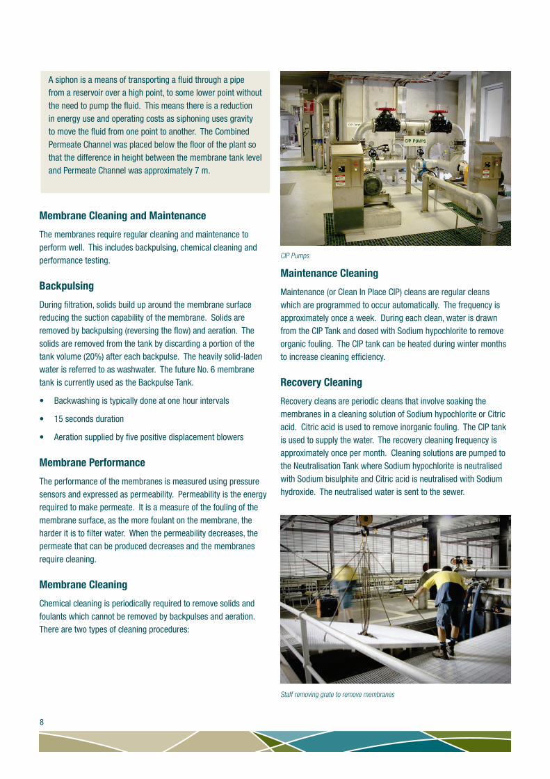
CIP Pumps
Staff removing grate to remove membranes
Maintenance Cleaning
Maintenance (or Clean In Place CIP) cleans are regular cleans which are programmed to occur automatically. The frequency is approximately once a week. During each clean, water is drawn from the CIP Tank and dosed with Sodium hypochlorite to remove organic fouling. The CIP tank can be heated during winter months to increase cleaning efficiency.
Recovery Cleaning
Recovery cleans are periodic cleans that involve soaking the membranes in a cleaning solution of Sodium hypochlorite or Citric acid. Citric acid is used to remove inorganic fouling. The CIP tank is used to supply the water. The recovery cleaning frequency is approximately once per month. Cleaning solutions are pumped to the Neutralisation Tank where Sodium hypochlorite is neutralised with Sodium bisulphite and Citric acid is neutralised with Sodium hydroxide. The neutralised water is sent to the sewer.
A siphon is a means of transporting a fluid through a pipe from a reservoir over a high point, to some lower point without the need to pump the fluid. This means there is a reduction in energy use and operating costs as siphoning uses gravity to move the fluid from one point to another. The Combined Permeate Channel was placed below the floor of the plant so that the difference in height between the membrane tank level and Permeate Channel was approximately 7 m.
Membrane Cleaning and Maintenance
The membranes require regular cleaning and maintenance to perform well. This includes backpulsing, chemical cleaning and performance testing.
Backpulsing
During filtration, solids build up around the membrane surface reducing the suction capability of the membrane. Solids are removed by backpulsing (reversing the flow) and aeration. The solids are removed from the tank by discarding a portion of the tank volume (20%) after each backpulse. The heavily solid-laden water is referred to as washwater. The future No. 6 membrane tank is currently used as the Backpulse Tank.
• Backwashing is typically done at one hour intervals
• 15 seconds duration
• Aeration supplied by five positive displacement blowers
Membrane Performance
The performance of the membranes is measured using pressure sensors and expressed as permeability. Permeability is the energy required to make permeate. It is a measure of the fouling of the membrane surface, as the more foulant on the membrane, the harder it is to filter water. When the permeability decreases, the permeate that can be produced decreases and the membranes require cleaning.
Membrane Cleaning
Chemical cleaning is periodically required to remove solids and foulants which cannot be removed by backpulses and aeration. There are two types of cleaning procedures:
8

The high level weir between the combined permeate trench and the post dosing area
Static Mixer
Membrane Integrity Testing (MIT)
The integrity of each membrane is monitored with MIT and online instrumentation. A MIT is used to detect leaks in the membrane system. This is done with pressurised air. If the membrane is damaged then air pressure will be lost. A visual inspection of the membranes, called a Bubble Test is then used to find the location of the leak.
Membrane Repair
The damaged membrane module is removed and put in a special tank. Pressurised air is used to find the exact location of the leak and silicone sealant injected to block the leak.
Post Dosing
The Permeate Collection Channel delivers permeate to the Post Dosing Tank, which consists of a series of two weirs and two static mixers. The permeate firstly flows over a high level weir, where it is dosed with Chlorine and Fluoride and then passes through the first static mixer. This is followed by Sodium Hydroxide dosing before passing through a second static mixer, and then over the second low level weir before gravitating to the Clear Water Tank. Water is stored here until it is pumped to the distribution network.
9

Clear Water Tank
Chlorine Dosing Room
Blower Room
Disinfection
During membrane filtration all pathogens are removed, however it is possible for recontamination in the distribution system. To ensure this doesn’t happen, the water is disinfected with Chlorine gas (Cl2) to a level of about 1mg/L. This provides a residual level of chlorine to all customers and ensures the water is safe to drink. Chlorine gas (Cl2) is stored in 920 kg drums
Fluoridation
It is a requirement of the NSW Department of Health that fluoride be added to drinking water to reduce the number of incidents of
tooth decay.
Fluoride is a naturally occurring ion that helps prevent tooth decay. In the Tweed River the natural level of fluoride is typically less than 0.1 mg/L. Additional fluoride is introduced to the drinking water to adjust the fluoride level to fall within the optimum range (0.95 to 1.05 mg/L) as required by the NSW Department of Health.
At Bray Park Water Treatment Plant this is achieved by adding liquid hydrofluosilicic acid (H2SiF6) to water.
Sodium Hydroxide Dosing
As the coagulation process occurs at a pH of around 6.4, there is a need to raise the pH of the final water to approximately 7.8. This is achieved by adding a diluted solution of sodium hydroxide (NaOH), (caustic soda).
Blower Room
The blower room contains:
• Membrane aeration blowers to provide aeration to assist in removing solids from the membranes.
• Compressors to provide compressed air for operating valves and MIT.
10

Chemical Storage Facility
Storage Tanks within Facility
Washwater Balance Tank
Chemical Storage Facility
This facility contains six separate chemicals. All chemicals are located within bunds to contain accidental spills. The facility has been designed for the safe and efficient delivery of bulk chemicals.
Sodium hypochlorite, NaOCl
• Function – chemical cleaning of membranes
• Storage capacity – 5,000L
Sodium hydroxide, NaOH
• Function – pH correction of filtered water
• Storage capacity – 80,000L
Aluminium sulphate, Al2(SO4)3
• Function – coagulation of raw water
• Storage capacity – 92,000L
Hydroflurosilicic Acid, H2SiF6
• Function – fluoridation of filtered water
• Storage capacity – 40,000L
Citric acid, C6H8O7
• Function – membrane cleaning
• Storage capacity – 1,500L
Sodium bisulphite, NaHSO3
• Function – neutralisation following sodium hypochlorite membrane cleaning
• Storage capacity – 500L
Washwater, Water Recycling and Waste Disposal
Washwater Balance Tank
Washwater is regularly removed from the membrane tanks and delivered to a Washwater Balance tank for treatment and recycling.
• Sized to store four complete membrane tank drains.
• Two submersible mixers ensure the solids stay in suspension.
The washwater is then pumped from the Balance Tank to a Sludge Thickener.
Sludge Thickener
A polymer solution is added to flocculate or bind the solids (sludge). The sludge separates from the water by settling to the bottom of the tank and is sent to the Sludge Holding Tank. The clarified water (supernatant) overflows and is collected in a Supernatant Holding Tank. The supernatant is recycled back into the raw water supply and sent back through the water treatment process.
11

Sludge Thickener Tank
Centrifuges dewater the solids
Dewatering Facility
The settled sludge is pumped to the Dewatering Facility where centrifuges further thicken and de-water the solids. The final solids are transported to industrial skip bins and sent to landfill. The liquid from the centrifuge is not suitable for return to the plant and is disposed of to the sewerage system via the Centrate Pump Station and Waste Holding Tank.
From Treatment to Tap
Distribution
The final treated water is delivered to a five megalitre storage tank before being pumped into the distribution network. Water then begins its journey to households and businesses via an intricate network of pipes, pumping stations and reservoirs before reaching your water meter and then your tap. This meter records the amount of water used by you.
• Pumping stations – 27 pumps used at various locations to move the treated drinking water up hill from the water treatment plant to reservoirs.
• Water mains and supply pipelines – the network of pipes that connect pumping stations to reservoirs and to houses and businesses. There are more than 726 kilometres of supply pipelines in the shire.
• Reservoirs - large tanks located throughout the Tweed to store treated water for nearby houses and businesses. They are usually located on hills or higher ground so that water can flow from them by gravity. There are 41 reservoirs with a storage capacity of 131 ML.
Treated water from the Bray Park Water Treatment Plant is pumped to Hospital Hill Reservoir before being distributed throughout the Tweed.
Dewatering Facility
Hospital Hill Reservoir
12
Parameter Target TypicalEscheridia coli 100% removal <1Gardia 99.99% removal Not sampledCryptosporidium 99.99% removal Not sampledViruses 100% removal Not sampledChlorine residual 1 mg/L 1 mg/LFluoride 1 mg/L 1 mg/LTurbidity <0.3 NTU 0.2 NTUTrue Colour <5 HU <1 HUpH 7.5 to 8.5 7.8Alkalinity 60-100 mg/L as CaCO
3 80 mg/L as CaCO3Hardness 40 - 60 mg/L as CaCO3 60 mg/L as CaCO3
Aluminium <0.1 mg/L 0.01 mg/LIron <0.1 mg/L <0.01 mg/LManganese <0.02 mg/L <0.01 mg/L
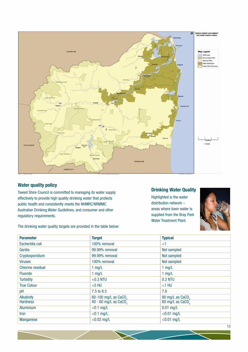
Highlighted is the water distribution network – areas where town water is supplied from the Bray Park Water Treatment Plant.
Water quality policyTweed Shire Council is committed to managing its water supply effectively to provide high quality drinking water that protects public health and consistently meets the NHMRC/NRMMC Australian Drinking Water Guidelines, and consumer and other regulatory requirements.
The drinking water quality targets are provided in the table below:
13
Drinking Water Quality