bre global classification report - fusion facades
TRANSCRIPT

Commercial in Confidence © BRE Global Ltd 2018 Page 1 of 22
BRE Global Classification Report Classification of fire performance in accordance with BR 135: 2013
Annex B for MIB Façades Limited
Prepared for: MIB Façades Limited
Date: 18th June 2018
Report Number: P110509-1001 Issue: 1
BRE Global Ltd Watford, Herts WD25 9XX Customer Services 0333 321 8811 From outside the UK: T + 44 (0) 1923 664000 F + 44 (0) 1923 664010 E [email protected] www.bre.co.uk
Prepared for: MIB Façades Limited Unit 3, Rhymney River Bridge Road Cardiff CF23 9AF Wales UK

Classification of fire performance in accordance with BR 135: 2013 Annex B.
Report Number: P110509-1001 Issue: 1
Commercial in Confidence © BRE Global Ltd 2018
Page 2 of 22
This report is made on behalf of BRE Global and may only be distributed in its entirety, without amendment, and with attribution to BRE Global Ltd to the extent permitted by the terms and conditions of the contract. Test results relate only to the specimens tested. BRE Global has no responsibility for the design, materials, workmanship or performance of the product or specimens tested. This report does not constitute an approval, certification or endorsement of the product tested and no such claims should be made on websites, marketing materials, etc. Any reference to the results contained in this report should be accompanied by a copy of the full report, or a link to a copy of the full report.
BRE Global’s liability in respect of this report and reliance thereupon shall be as per the terms and conditions of contract with the client and BRE Global shall have no liability to third parties to the extent permitted in law.
Prepared by
Name Mohamed Abukar
Position Fire Test Engineer
Signature
Authorised by
Name Stephen Howard
Position Director Fire Testing and Certification
Date 18th June 2018
Signature

Classification of fire performance in accordance with BR 135: 2013 Annex B.
Report Number: P110509-1001 Issue: 1
Commercial in Confidence © BRE Global Ltd 2018
Page 3 of 22
Table of Contents
1 Introduction 5 2 Details of the Classified Product 6
2.1 Description of substrate 6
2.2 Description of product 7
2.3 Installation sequence 8
2.4 Installation of Specimen 9
3 Product Specification 10 4 Supporting Evidence 17
4.1 Test reports 17
4.2 Test results 17
4.3 Mechanical performance 18
4.4 System damage 18
4.4.1 Aluminium panels 18 4.4.2 Aluminium rail substructure 19 4.4.3 Top hat sections 19 4.4.4 Stone wool insulation 19 4.4.5 Horizontal (intumescent) cavity barriers 20 4.4.6 Vertical (compression) cavity barrier 20 4.4.7 Structural insulated panels 21
5 Classification and Field of Application 22
5.1 Reference of classification 22
5.2 Classification 22
5.3 Field of application 22
6 Limitations 22

Classification of fire performance in accordance with BR 135: 2013 Annex B.
Report Number: P110509-1001 Issue: 1
Commercial in Confidence © BRE Global Ltd 2018
Page 4 of 22
CLASSIFICATION OF FIRE PERFORMANCE IN ACCORDANCE WITH BR 135:2013 Annex B
Sponsor: MIB Façades Limited, Unit 3, Rhymney River Bridge Road, Cardiff, CF23 9AF, Wales, UK
Prepared by: BRE Global Ltd, BRE, Bucknalls Lane, Garston, Watford, WD25 9XX, England
Product name: 136mm-thick MetSIP panel, 60mm-thick Rockwool insulation, 80mm-deep cavity,
Classification report No.: P110509-1001
Issue number: 1
Date of issue: 18th June 2018
This classification report consists of 22 pages and may only be used or reproduced in its entirety.
3mm-thick Fusion Facades aluminium cassette panels
Classification of fire performance in accordance with BR 135: 2013 Annex B.
Report Number: P110509-1001 Issue: 1
Commercial in Confidence © BRE Global Ltd 2018
Page 5 of 22
1 Introduction
This report presents the classification of the system detailed in section 2. The classification is carried out in accordance with the procedures given in BR 135 – ‘Fire performance of external thermal insulation for walls of multi-storey buildings’, Third edition, Annex B 2013. This classification should be read in conjunction with this document and the associated test reports referenced in section 4.

Classification of fire performance in accordance with BR 135: 2013 Annex B.
Report Number: P110509-1001 Issue: 1
Commercial in Confidence © BRE Global Ltd 2018
Page 6 of 22
2 Details of the Classified Product
2.1 Description of substrate The test specimen was installed onto wall number 2 of the BRE Global cladding test facility. This apparatus is representative of a structural steel framed building and consists of a structural steel test frame with a vertical main test wall and a vertical return wall at a 90º angle to and at one side of the main test wall.

Classification of fire performance in accordance with BR 135: 2013 Annex B.
Report Number: P110509-1001 Issue: 1
Commercial in Confidence © BRE Global Ltd 2018
Page 7 of 22
2.2 Description of product Table 1. List of component parts used in the construction of the system
Item Description
1 MetSIP panel).
2 136mm-thick MetSIP panels (120mm-thick polyurethane core between two layers of 8mm-thick cement board).
3 90mmÍ
4 65mm-deepÍ
5 120mm-deepÍ42mm-wideÍ
6 60mm-deepÍ42mm-wideÍ
7 60mm-thick Rockwool Duoslab insulation.
8 60mm-wideÍ40mm-deep ‘L’-shaped aluminium rails.
9 90mm-thickÍ187mm-deep Siderise Lamatherm EW-FS60 vertical cavity barrier.
10 120mm-thickÍ187mm-deep Siderise Lamatherm EW-FS120 vertical cavity barrier.
11 120mm-thickÍ152mm-deep Siderise Lamatherm RH25G-120/60 horizontal open state cavity barrier with intumescent strip.
12
13 Reynaers CS 86 aluminium window frame (80mm-deep, aperture dimensions: 1850mm-wideÍ1845mm-high)
15mm-thick British Gypsum Gyproc Fireline plasterboard (fitted to the rear face of the
125mm Fusion Facades ‘L’-shaped angles.
80mm-wide top hat section (with 25mm flange either side giving a total width of 130mm) Fusion Facades filled with green stone wool insulation.
4mm-thick Fusion Facades ‘L’-shaped brackets.
3mm-thick Fusion Facades aluminium cassette panels with 40mm return (PPC finish).
4mm-thick Fusion Facades ‘L’-shaped brackets.

Classification of fire performance in accordance with BR 135: 2013 Annex B.
Report Number: P110509-1001 Issue: 1
Commercial in Confidence © BRE Global Ltd 2018
Page 8 of 22
2.3 Installation sequence ‘L’-shaped angles (90mmÍ125mm) were fitted along the head and base of the ‘floor slabs’ of the structural steel frame, flush with and returning in line with the front external face. MetSIP panels with a nominal dimension of 2510mm-highÍ1215mm-wideÍ136mm-thick were positioned between the ‘floor slabs’ and fixed to the ‘L’-shaped angles at 100mm-200mm centres with 38mmÍ5mm screws. The total thickness of the SIP panel consisted of two 8mm-thick cement boards either side of 120mm of polyurethane foam insulation.
A single layer of 15mm-thick plasterboard was fixed to the rear face and outside edges of the MetSIP panels with 35mmÍ3.5mm screws at 300mm centres. The MetSIP panels were fitted flush against the combustion chamber so plasterboard installation was omitted from this location.
Horizontally orientated top hat sections (profile: 25mmÍ65mmÍ80mmÍ65mmÍ25mm, overall: 130mm-wideÍ65mm-highÍ3mm-thick) were fixed to the front face of the MetSIP panel at nominal 500mm-680mm vertical centres using 33mmÍ5mm screws at nominal 560mm-600mm horizontal centres. Top hat sections contained green stone wool insulation (nominally 80mm-wideÍ65mm-thick).
‘L’-shaped helping hand brackets (60mm-highÍ42mm-wideÍ4mm-thick) were fixed to the top hat sections (at nominal 900mm horizontal centres) in three columns on the main wall and a single column on the wing wall. Each bracket was fixed with two 33mmÍ5mm screws.
Longer ‘L’-shaped helping hand brackets (120mm-highÍ42mm-wideÍ4mm-thick) were fixed to the ‘floor slabs’, in line with the columns of smaller brackets, also with two 33mmÍ5mm screws. Black adhesive sheet covered the ‘floor slabs’.
‘L’-shaped angle (86mmÍ65mm) was fixed to the top hat sections and capped the vertical outside edges of the cladding system.
Two columns of Siderise Lamatherm EW-FS60 green stone wool vertical cavity barriers (90mm-thickÍ187mm-deep), were pressed onto folded steel skewers (300mm-longÍ25mm-wide, fixed to the MetSIP panels at 200mm centres with a 38mmÍ5mm screw) towards the outside edges of the cladding system: 2560mm from main-wing wall junction (main wall) and 1510mm from main-wing wall junction (wing wall), with approximately 10mm compression. Two Siderise Lamatherm EW-FS120 vertical cavity barriers (120mm-thickÍ187mm-deep) were fitted, approximately 55mm each side of the combustion chamber, up to the height of the first horizontal cavity barrier with approximately 10mm compression.
Siderise Lamatherm RH25 horizontal ‘open state’ cavity barriers (120mm-thickÍ152mm-deep) with intumescent strip were fitted onto face-turned steel skewers in three rows across the cladding system approximately: 500mm, 3000mm and 5,500mm above the combustion chamber opening.
60mm-thick Rockwool Duoslab insulation filled the void between top hat sections and were fixed through the centre with a single stainless steel screw and washer.
‘L’-shaped aluminium rails (60mm-wideÍ40mm-deep) were fixed into the helping hand brackets (three columns on the main wall, one column on the wing wall) with fastener screws. The aluminium rails passed through the horizontal cavity barriers so that the intumescent strip was on the front face of the rail.
The aluminum cassette panels (nominal dimensions: 2990mm-highÍ805mm-wideÍ3mm-thick with 40mm-return) were fixed onto the rails at nominal 500mm vertical centres, using 30mmÍ5mm screws. The gap between adjacent panels was 23mm. At the outside edges of the test specimen the aluminium panels were folded, capping the sides of the cladding system. Vent slot perforations were included along the horizontal section of the panels that returned into the head of the combustion chamber opening.

Classification of fire performance in accordance with BR 135: 2013 Annex B.
Report Number: P110509-1001 Issue: 1
Commercial in Confidence © BRE Global Ltd 2018
Page 9 of 22
An 80mm-deep aluminium window frame (reported to be Reynaers CS 86), with ventilation grill (open position selected for the fire test) along horizontal edge, was fixed with 95mmÍ5.5mm screws at 850mm vertical centres within the combustion chamber opening. At the location of the window frame the combustion chamber opening was reduced by 105mm horizontally and 70mm vertically.
2.4 Installation of Specimen All test materials were supplied and installed by the sponsor. BRE Global were not involved in the sample selection process and therefore cannot comment upon the relationship between samples supplied for test and the product supplied to market.

Classification of fire performance in accordance with BR 135: 2013 Annex B.
Report Number: P110509-1001 Issue: 1
Commercial in Confidence © BRE Global Ltd 2018
Page 10 of 22
3 Product Specification
Figure 1. Layout of Fusion Facades panels and numbering system used for reporting. Not to scale

Classification of fire performance in accordance with BR 135: 2013 Annex B.
Report Number: P110509-1001 Issue: 1
Commercial in Confidence © BRE Global Ltd 2018
Page 11 of 22
Figure 2. Full-height view of finished Fusion Facades cladding system prior to test.

Classification of fire performance in accordance with BR 135: 2013 Annex B.
Report Number: P110509-1001 Issue: 1
Commercial in Confidence © BRE Global Ltd 2018
Page 12 of 22
Figure 3. Cross-section of tested system (supplied by Test Sponsor).
Note: -tophat sections embedded in the insulation layer are not visible on drawing.
Classification of fire performance in accordance with BR 135: 2013 Annex B.
Report Number: P110509-1001 Issue: 1
Commercial in Confidence © BRE Global Ltd 2018
Page 13 of 22
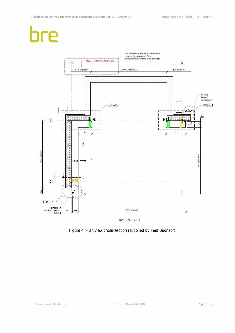
Figure 4. Plan view cross-section (supplied by Test Sponsor).

Classification of fire performance in accordance with BR 135: 2013 Annex B.
Report Number: P110509-1001 Issue: 1
Commercial in Confidence © BRE Global Ltd 2018
Page 14 of 22
Figure 5. Plan view cross-section (supplied by Test Sponsor).

Classification of fire performance in accordance with BR 135: 2013 Annex B.
Report Number: P110509-1001 Issue: 1
Commercial in Confidence © BRE Global Ltd 2018
Page 15 of 22
Figure 6. Side view cross-section (supplied by Fusion Facades).

Classification of fire performance in accordance with BR 135: 2013 Annex B.
Report Number: P110509-1001 Issue: 1
Commercial in Confidence © BRE Global Ltd 2018
Page 16 of 22
Figure 7. Detail of perforations in rainscreen at window opening (Fusion Facades).

Classification of fire performance in accordance with BR 135: 2013 Annex B.
Report Number: P110509-1001 Issue: 1
Commercial in Confidence © BRE Global Ltd 2018
Page 17 of 22
4 Supporting Evidence
4.1 Test reports
Name of Laboratory Name of sponsor Test reports/extended
application report Nos. Test method / extended application rules & date
BRE Global, BRE
MIB Façades Limited P110509-1000 BS 8414-2:2015 + A1:2017
4.2 Test results
Test method Parameter No. tests
Results
Fire spread test result
time, ts (min)
Compliance with parameters in Annex B
BR135:2013
BS 8414-2:2015
+ A1:2017
External fire spread
1
>15 minutes
Compliant
Internal fire spread >15 minutes
Compliant
System burn through >15 minutes Compliant
Classification of fire performance in accordance with BR 135: 2013 Annex B.
Report Number: P110509-1001 Issue: 1
Commercial in Confidence © BRE Global Ltd 2018
Page 18 of 22
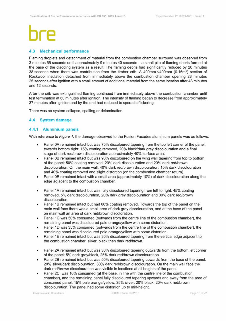
4.3 Mechanical performance Flaming droplets and detachment of material from the combustion chamber surround was observed from 3 minutes 55 seconds until approximately 9 minutes 40 seconds – a small pile of flaming debris formed at the base of the cladding system as a result. The flaming debris had significantly reduced by 20 minutes 38 seconds when there was contribution from the timber crib. A 400mmÍ400mm (0.16m2) section of Rockwool insulation detached from immediately above the combustion chamber opening 28 minutes 25 seconds after ignition with a small amount of additional material from the same location after 48 minutes and 12 seconds.
After the crib was extinguished flaming continued from immediately above the combustion chamber until test termination at 60 minutes after ignition. The intensity of flaming began to decrease from approximately 37 minutes after ignition and by the end had reduced to sporadic flickering.
There was no system collapse, spalling or delamination.
4.4 System damage
4.4.1 Aluminium panels With reference to Figure 1,
• Panel 0A remained intact but was 75% discoloured tapering from the top left corner of the panel, towards bottom right: 15% coating removed, 20% black/dark grey discolouration and a final stage of dark red/brown discolouration approximately 40% surface area.
• Panel 0B remained intact but was 90% discoloured on the wing wall tapering from top to bottom of the panel: 50% coating removed, 20% dark discolouration and 20% dark red/brown discolouration. On the main wall: 40% dark red/brown discolouration, 15% dark discolouration and 40% coating removed and slight distortion (on the combustion chamber return).
• Panel 0E remained intact with a small area (approximately 10%) of dark discolouration along the edge adjacent to the combustion chamber.
• Panel 1A remained intact but was fully discoloured tapering from left to right: 45% coating removed, 5% dark discolouration, 20% dark grey discolouration and 30% dark red/brown discolouration.
• Panel 1B remained intact but had 80% coating removed. Towards the top of the panel on the main wall face there was a small area of dark grey discolouration, and at the base of the panel on main wall an area of dark red/brown discoloration.
• Panel 1C was 50% consumed (outwards from the centre line of the combustion chamber), the remaining panel was discoloured pale orange/yellow with some distortion.
• Panel 1D was 35% consumed (outwards from the centre line of the combustion chamber), the remaining panel was discoloured pale orange/yellow with some distortion.
• Panel 1E remained intact but was 30% discoloured tapering from the vertical edge adjacent to the combustion chamber: silver, black then dark red/brown.
• Panel 2A remained intact but was 30% discoloured tapering outwards from the bottom left corner of the panel: 5% dark grey/black, 25% dark red/brown discolouration.
• Panel 2B remained intact but was 50% discoloured tapering upwards from the base of the panel: 20% silver/dark discolouration, 30% dark red/brown discolouration. On the main wall face the dark red/brown discolouration was visible in locations at all heights of the panel.
• Panel 2C, was 10% consumed (at the base, in line with the centre line of the combustion chamber), and the remaining panel fully discoloured tapering upwards and away from the area of consumed panel: 15% pale orange/yellow, 35% silver, 20% black, 20% dark red/brown discolouration. The panel had some distortion up to mid-height.
the damage observed to the Fusion Facades aluminium panels was as follows:

Classification of fire performance in accordance with BR 135: 2013 Annex B.
Report Number: P110509-1001 Issue: 1
Commercial in Confidence © BRE Global Ltd 2018
Page 19 of 22
• Panel 2D, was 5% consumed (at the base, in line with the centre line of the combustion chamber), and the remaining panel 50% discoloured tapering upwards and away from the area of consumed panel: 10% pale orange/yellow, 30% silver, 10% black and a thin dark red/brown outline. The panel had slight distortion along the base.
• Panel 2E remained intact but was 10% discoloured tapering outwards from the bottom right corner of the panel: <5% silver, <5% dark grey/black, 5% dark red/brown discolouration.
• Panel 3A remained intact and in place with no visible signs of damage. • Panels 3B-3C remained intact and in place with dark red/brown discolouration along the bottom
edge. • Panels 3D-3E remained intact and in place with no visible signs of damage.
4.4.2 Aluminium rail substructure The central aluminium ‘L’-shaped rail on the main wall was fully consumed up to the height of the second row horizontal cavity barrier. Above the second row horizontal cavity barrier the rail remained intact and in place with surface discolouration to approximately 100mm above the third row horizontal cavity barrier.
The ‘L’-shaped rails in line with the vertical edges of the combustion chamber opening were fully consumed up to the height of the first row horizontal cavity barrier. Above the first row horizontal cavity barrier the rail remained intact and in place with minor distortion (up to the second row horizontal cavity barrier) and surface discolouration to the height of the third row horizontal cavity barrier.
The ‘L’-shaped rail on the wing wall had some distortion immediately above the first horizontal cavity barrier and minor smoke staining up to the height of the second row horizontal cavity barrier.
4.4.3 Top hat sections The aluminium of the top hat section located immediately above the combustion chamber opening had been consumed across the majority of the opening width. The stone wool insulation contained within the top hat section had detached where the aluminium had melted.
The front face of the aluminium top hat section located on the main wall, approximately 1200mm above the combustion chamber opening, had been consumed across a width approximately 1200mm. The stone wool insulation contained within the top hat section remained in place.
The front face of the aluminium top hat section located on the main wall, approximately 2100mm above the combustion chamber opening, had been consumed across a width approximately 250mm. The stone wool insulation contained within the top hat section remained in place.
The top hat section located approximately 2750mm above the combustion chamber opening remained intact and in place with coating removed in line with the combustion chamber. The ‘L’-shaped bracket fixed to the top hat section on the centre line of the combustion chamber was 90% consumed.
The top hat sections were discoloured up to the height of the third horizontal cavity barrier. Smoke staining was most concentrated on the main wall in line with the combustion chamber opening.
4.4.4 Stone wool insulation A 400mmÍ400mm section of insulation, located between the combustion chamber opening and the first horizontal cavity barrier, detached during the test. A similar sized section, located directly adjacent and in line with the centre line of the combustion chamber, had peeled away from the surface of the MetSIP panel but remained attached. All other insulation slabs remained intact and in place with heat damage and discolouration visible on both walls, between the vertical cavity barriers, up to the height of the third horizontal cavity barrier.

Classification of fire performance in accordance with BR 135: 2013 Annex B.
Report Number: P110509-1001 Issue: 1
Commercial in Confidence © BRE Global Ltd 2018
Page 20 of 22
Up to the height of the first horizontal cavity barrier, on the main wall, the insulation that remained attached during the test had yellow discolouration. On the wing wall, brown smoke staining extended from approximately 600mm above ground level to the first horizontal cavity barrier.
Between the first and second horizontal cavity barrier, on the main wall, significant amounts of insulation detached once the cladding system was extinguished post-test. From observations prior to this and the insulation that remained on the wall it can be commented that the insulation in the central flame plume zone, where the aluminium had been consumed, had brown/black discolouration, rough texture and had started to contract so that gaps were forming between slabs up to the height of the first row of top hat sections. Between the first and second row of top hat sections the insulation had yellow/brown discolouration and appeared to have a rough texture in a 500mm-width on the centre line of the combustion chamber. At the outside edge of the main wall yellow discolouration dominated with some darker smoke staining immediately above the first horizontal cavity barrier and in the top left corner. On the wing wall, brown smoke staining was consistent between the first and second horizontal cavity barrier.
Between the second and third horizontal cavity barrier, on both the main and wing wall, yellow/orange discolouration was visible to approximately mid-height – orange at the outside edge of the main wall, paler along the centre line of the combustion chamber, orange/yellow on the wing wall. Above mid-height, black smoke staining was visible on the main wall and to approximately mid-width on the wing wall.
At the top of the cladding system, a band of dark smoke staining, approximately 200mm-wide, was visible across the main wall. Elsewhere, the insulation appeared to be undamaged.
4.4.5 Horizontal (intumescent) cavity barriers The cavity barriers remained intact and in place for the duration of the test. Upon extinguishing the cladding system post-test the first horizontal cavity barrier in line with the combustion chamber detached.
The intumescent strip of the first row of horizontal cavity barriers appeared to have activated across the full width. Subsequent breakdown and detachment of the intumescent material occurred in line with the combustion chamber and to mid-width on the wing wall.
The intumescent strip of the second row of horizontal cavity barriers appeared to have activated across the full width. Subsequent breakdown and detachment of the intumescent material occurred in line with the combustion chamber.
The intumescent strip of the third row of horizontal cavity barriers appeared to have activated across the full width of the main wall. There was a small area, approximately 100mm-wide, towards the main-wing wall junction where the intumescent strip had completely detached. Partial detachment of the intumescent strip occurred in line with the combustion chamber opening. On the wing wall, the intumescent strip had partially activated up to the vertical cavity barrier.
4.4.6 Vertical (compression) cavity barrier The vertical cavity barriers at the outside edge of the main and wing wall remained intact and in place except for 100mm-long sections approximately 2500mm above the combustion chamber opening that had partially detached. This was believed to have occurred during post-test deconstruction. Smoke staining was visible on the inside edge of the main wall vertical barrier up to the height of the third horizontal cavity barrier. Smoke staining was visible on the inside edge and front face of the wing wall vertical barrier from 600mm above ground level up to the height of the second horizontal cavity barrier.
The vertical cavity barriers either side of the combustion chamber had dark discolouration on the inside edge but remained intact and in place.

Classification of fire performance in accordance with BR 135: 2013 Annex B.
Report Number: P110509-1001 Issue: 1
Commercial in Confidence © BRE Global Ltd 2018
Page 21 of 22
4.4.7 Structural insulated panels The external cement board of the MetSIP panels was cracked and partially detached in two locations: directly above and at the top of the outside edge of the combustion chamber.
Directly above the combustion chamber the cement board was significantly cracked where the Rockwool insulation had detached but mostly remained attached – large openings were present along the cracks which resulted in the majority of the polyurethane core being consumed. The rear cement board had cracked on the centre line of the combustion chamber and a section (approximately 300mm-wideÍ100mm-high) had detached to expose the roof of the combustion chamber.
At the top of the outside edge of the combustion chamber, an area of external cement board (150mm-wide(max)Í400mm-high) had detached. The exposed insulation had been consumed by an additional 50mm to a width approximately 200mm. The rear cement board had detached from an area in the same location approximately 100mm-wide(max)Í250mm-high). System burn-through was not observed during the test, damage may have been increased by post-test firefighting actions.
Between the first and second horizontal cavity barrier, the MetSIP panels remained intact and in place. On the main wall, the external cement board was charred in bands approximately 1800mm-wideÍ300mm-high at the locations of the top hat sections. Brown smoke staining was visible between the bands of charring. Additional charring was visible directly above the first row horizontal cavity barrier on the centre line of the combustion chamber. The wing wall appeared to be undamaged.
Between the second and third horizontal cavity barrier, the MetSIP panels remained intact and in place. On the main wall, a small amount of brown smoke staining was visible above and below the position of the top hat sections. The wing wall appeared to be undamaged.
Above the third horizontal cavity barrier, the MetSIP panels on both the main and wing walls appeared to be undamaged.

Classification of fire performance in accordance with BR 135: 2013 Annex B.
Report Number: P110509-1001 Issue: 1
Commercial in Confidence © BRE Global Ltd 2018
Report Ends
Page 22 of 22
5 Classification and Field of Application
5.1 Reference of classification This classification has been carried out in accordance with Annex B of BR 135 – ‘Fire performance of external thermal insulation for walls of multi-storey buildings.’ Third Edition 2013.
5.2 Classification
The system described in this classification report has been tested and met the performance criteria set in Annex B of BR 135:2013.
5.3 Field of application This classification is valid only for the system as installed and detailed in Section 2 of this classification report and the associated details found in the related test reports, referenced in Section 4.
6 Limitations
This classification document does not represent type approval or certification of the product.
The classification applies only to the system as tested and detailed in the classification report. The classification report can only cover the details of the system as tested. It cannot state what is not covered. When specifying or checking a system it is important to check that the classification documents cover the end-use application.
The specification and interpretation of fire test methods are the subject of ongoing development and refinement. Changes in associated legislation may also occur. For these reasons, it is recommended that the relevance of test and classification reports over five years old should be considered by the user. The laboratory that issued the report will be able to offer, on behalf of the legal owner, a review of the procedures adopted for a particular test or classification to ensure that they are consistent with current practices, and if required may endorse the report.