break-up and atomization of a round water jet by a high...
TRANSCRIPT

J. Fluid Mech. (1998), �ol. 357, pp. 351–379. Printed in the United Kingdom
# 1998 Cambridge University Press
351
Break-up and atomization of a round water jet bya high-speed annular air jet
By J. C. LASHERAS1, E. VILLERMAUX2
E. J. HOPFINGER2
"Department of Applied Mechanics and Engineering Sciences, University of California,San Diego, La Jolla, CA 92093-0411, USA
#LEGI-CNRS}UJF-INPG, BP 53, 38041 Grenoble Cedex, France
(Received 11 July 1996 and in revised form 16 October 1997)
The near- and far-field break-up and atomization of a water jet by a high-speedannular air jet are examined by means of high-speed flow visualizations and phaseDoppler particle sizing techniques. Visualization of the jet’s near field andmeasurements of the frequencies associated with the gas–liquid interfacial instabilitiesare used to study the underlying physical mechanisms involved in the primary break-up of the water jet. This process is shown to consist of the stripping of water sheets,or ligaments, which subsequently break into smaller lumps or drops. An entrainmentmodel of the near-field stripping of the liquid is proposed, and shown to describe themeasured liquid shedding frequencies. This simplified model explains qualitatively thedependence of the shedding frequency on the air}water momentum ratio in bothinitially laminar and turbulent water jets. The role of the secondary liquid break-up inthe far-field atomization of the water jet is also investigated, and an attempt is madeto apply the classical concepts of local isotropy to explain qualitatively themeasurement of the far-field droplet size distribution and its dependence on the waterto air mass and momentum ratios. Models accounting for the effect of the localturbulent dissipation rate in the gas on both the break-up and coalescence of thedroplets are developed and compared with the measurements of the variation of thedroplet size along the jet’s centreline. The total flux of kinetic energy supplied by thegas per unit total mass of the spray jet was found to be the primary parameterdetermining the secondary break-up and coalescence of the droplets in the far field.
1. Introduction
The understanding of the break-up and atomization of liquid jets is fundamental totwo-phase flow combustion and propulsion problems (Sutton 1992). In liquidpropellant rocket engines, the reactants (fuel and oxidizer) are often supplied in anarray of injectors where in each injector a jet of liquid oxygen is atomized by a high-speed annular hydrogen gas jet (Burick 1972). These types of atomizers when used inconventional air-supplied combustion applications are generically referred to as twin-fluid atomizers (Lefebvre 1989). Owing to the complexity of the underlying physicalprocesses involved in the break-up of a liquid jet by a high-speed turbulent gas jet, thistype of atomization is still poorly understood. Quantitative observations of the nearfield and measurements of the drop size and liquid void fraction are difficult to make,and often subject to large errors. Most of the past studies have focused on measuringthe distribution of drop sizes at the spray’s centreline at a certain fixed distancedownstream of the nozzle (x}D& 30). From these point measurements, correlations
352 J. C. Lasheras, E. Villermaux and E. J. Hopfinger
have been established for the drop size as a function of the flow parameters and theinjector geometry (see for instance Lefebvre 1989; Gomi 1985). The dependenceof the droplet size (typically characterized by the Sauter mean diameter defined byD
$#¯3N
id$i}3N
id#i
where diis the diameter of each droplet, and N
ithe number
of droplets per unit volume in each size group) on the gas velocity has been found tobe approximated by a power law D
$#CU−n
gwith n ranging usually from 0.8 to 1.3
(Ingebo 1991), possibly reaching a value as large as 2 in exceptional cases (Nukiyama& Tanasawa 1939; Gomi 1985). There is no convincing physical explanation for thesepower laws or even for why the drop size, in general, should follow a power-lawdependence on the initial gas velocity. As high-speed photography and non-intrusivelaser-based diagnostics have become more readily available, it is now possible tovisualize the near field (Farago & Chigier 1992; Hopfinger & Lasheras 1994;Hardalupas & Whitelaw 1994; Englebert, Hardalupas & Whitelaw 1995) and toperform accurate measurements of the droplet size throughout the spray, thus openingnew avenues in the development of theoretical models.
An early visual study of water jet instability, with or without coflowing orcounterflowing air of velocity comparable to the liquid velocity, was performed byHoyt & Taylor (1977). Their results indicate that in the near field the air stream haspractically no influence on the instability which originates in the vorticity sheet of thewater jet. Only further downstream, when perturbations are amplified, does theaerodynamic form drag on the liquid protrusions become active, and the air streamcontributes to further destabilization of the water jet. This indicates that for the gasstream to affect the liquid jet instability appreciably in the near field, the gasmomentum flux per unit volume has to be larger than or equal to the liquid momentumflux per unit volume. Surface tension is, of course, an important parameter andimposes a cut-off in the length scale of the amplified perturbations.
In the case of interest here, where a low-speed liquid jet is injected at the central axisof a high-speed coaxial air jet, the liquid break-up and droplet atomization can bedivided into a near-field primary break-up region, and a far-field secondary break-upregion. Both primary and secondary break-up have received considerable attention inthe past. The primary break-up, which is dominant in the first few jet diameters, isessentially related to the non-miscible shear instability, and results in the stripping ofthe liquid jet by the high shear forces at the gas}liquid interface. Further downstream,droplet atomization may also occur from the deformation forces exerted on thedroplets by the turbulent motion of surrounding air, a process known as secondaryatomization.
Surface-tension-driven instability of liquid jets dates back to Rayleigh (1879), andWeber (1931) who included the effect of the viscosity of the liquid. These theories arerelevant to ligament break-up in the near field (e.g. Lefebvre 1980). The destabilizationof the liquid jet close to the nozzle exit is a Kelvin–Helmholtz type of instability wheresurface tension acts as a stabilizing force and imposes a lower cut-off for the waveswhich can grow (see Chandrasekhar 1961). This cut-off is given by a critical Webernumber (Weber 1931; Chandrasekhar 1961). More specific theoretical models of thebreak-up of liquid sheets and jets in a gas stream have been developed subsequently(Mayer 1993; Dombrowski & Johns 1963; Adelberg 1968; and others). These modelsgive correlations for the dependence of drop size on gas velocity and sheet thickness.Numerical simulations of two-dimensional interfacial instability by Mayer (1993),Keller et al. (1994) and Zaleski (1995) have also shown sheet formation and break-up,but these simulations are limited to low Reynolds number.
Individual liquid lumps stripped off from the central liquid core may still undergo

Break-up and atomization of a round water jet 353
secondary break-up if the forces exerted by the turbulent air exceed the confinementdue to the surface tension and the liquid viscosity. Fundamental studies of the break-up of individual drops submerged in turbulent flows were made by Kolmogorov(1949), Lane (1951), Hinze (1955), and many others. Three forces are involved in thesplitting of the liquid, namely surface tension, viscous, and inertia forces. Fromdimensional arguments, Hinze showed that if τ is the force per unit area exerted by thegas on the surface of the droplet, the deformation process depends on twodimensionless groups, and a critical generalized Weber number, We!
c, can then be
defined as We!c¯We
c[1Φ(N )], where N¯µ}(ρ
lσd )"/# is a viscous group (or
Ohnesorge number) which accounts for the viscosity of the liquid, and Wec¯ τd}σ is
the critical Weber number for the case of zero dispersed-phase viscosity.Theoretical and experimental studies of single-drop shear break-up are numerous,
and the reader is referred to Pilch & Erdman (1987) where the different scenariosdepending on Weber number are discussed. When a water drop of size d is suddenlyexposed to a uniform air flow of relative constant speed (u
l®u
g) break-up will occur
if the shear Weber number exceeds a critical value, Wes¯ ρ
l(u
l®u
g)# d}σ" (We
s)c
(Hanson, Domich & Adam 1963). For a water droplet in air, Hinze (1955) showed that(We
s)cis of the order 10 (excluding here any resonant vibration or acceleration break-
up). When the Reynolds number of the gas is very large, as it is in our application (i.e.of the order of 10% to 10&), the motion of the gas is turbulent and the droplet may alsobreak due to the dynamic pressure caused by the surrounding turbulence. A model forsuch a turbulence break-up was proposed by Kolmogorov (1949) and Hinze (1955).They defined a turbulent Weber number based on the difference in turbulent velocityon the scale equal to the drop size We
t¯ ρ
gu(d )# d}σ. Kolmogorov then postulated
that when Wetis greater than a critical value, (We
t)c, atomization of the liquid occurs
as the dynamic pressure forces from the turbulent motion are sufficiently large toovercome the confinement of the surface tension. Hinze (1955) found that owing toresonant vibrations, the turbulent critical Weber number is typically smaller than 1,and he estimated a value of 0.59 from Clay’s (1940) experiments.
In this paper we report an experimental study of the near- and far-field regions ofthe break-up of a round water jet by a high-speed annular air jet. Measurements of thefrequency of the near-field interfacial instabilities are used to investigate the underlyingphysical mechanisms involved in the primary liquid break-up. The far-field secondaryatomization is analysed by means of detailed measurements of both the droplet size andvelocity distribution as well as turbulent characteristics of the atomizing air. In §2 wepresent the experimental set-up and procedures, and in §3 discuss the results of thenear-field primary break-up. The primary break-up is first classified according to thewater to air momentum ratio, the aerodynamic Weber number and the water and airReynolds numbers. Measurements of the liquid shedding frequencies in each of thebreak-up modes are then presented, and a model of the near-field stripping is proposed.Finally, in §4 the role of the secondary break-up and quantitative relationshipsdescribing the influence of the turbulence on the break-up and coalescence of the dropsis presented. Simplified models accounting for the local dissipation rate are thencompared to the experimental evidence in §5.
2. Experimental conditions and procedures
The injector geometry is shown schematically in figure 1. The experiments areconducted at atmospheric pressure and water and air are used as working fluids. Thejet nozzles are straight long tubes so that conditions at the outlet are a developed pipe

354 J. C. Lasheras, E. Villermaux and E. J. Hopfinger
Water
Four peripheral air inlets
6°
110 mm28 mm
dl Dl Dg
F 1. Coaxial jet nozzle configuration.
flow for the central water jet and a channel flow for the annular air jet. The innertube is 110 mm long. It has an outer diameter of 4.2 mm and an inner diameter ofdl¯ 2.9 mm which is expanded through a 6° half cone angle to an outlet diameter
Dl¯ 3.8 mm.This diffuser at the outletmodifies the pipe flowvelocity profile somewhat,
but it does not lead to flow separation in any of the experimental conditions reportedhere. The absence of separation was verified for the case of turbulent conditions at theexit of the water jet in a scale-up flow facility by Rehab, Villermaux & Hopfinger(1997). The nozzle diameters of the annular air jet are D
g¯ 5.6 mm and d
g¯ 4.2 mm,
giving a gap spacing h¯ 0.7 mm over a length of 28 mm. The water nozzle velocityUlwas varied from 0.15 to 1.5 m s−", and the air velocity U
gfrom 20 to 250 m s−". These
are section-averaged velocities, which are monitored with precision flow meters. Theuniformity of the air flow at the nozzle’s exit was checked with a total head tube of0.7 mm outer diameter. In order to prevent any recirculation of the water spray in thetest rig which could contaminate the measurements, we placed absorbing material ina receiving reservoir located far downstream (x}D
g" 300). Furthermore, extreme care
was taken to prevent contamination from any possible recirculating flow by removingthe spray reaching the damping reservoir with several suction fans.
Instantaneous photographs were taken with a CCD Sony video camera, with aframing rate 1}30 s and a shutter speed% 10−% s. Forward light scattering was used forthese instantaneous images which have an average pixel resolution of about 20 µm. Ahigh-speed video camera (Ektapro with a framing rate 1000 to 6000 frames}second)was also used to inspect the near-field break-up event and to measure the accelerationof the liquid by the air stream. The liquid shedding frequency was measured with alaser-photodiode arrangement placed one diameter downstream of the nozzles. Thissystem consisted of a laser beam of 0.3 mm in diameter placed tangentially to theundisturbed water jet in the direction perpendicular to the jet’s axis. As the interfacialinstability developed, a photodiode recorded the attenuation signal produced as theinterfacial waves attenuated the beam intensity. These waves are believed to be theprecursors of the sheet}ligaments separating from the edge of the liquid jet. Theattenuation signal from the photodiode was digitized at a rate of 10000 samples persecond on a Le Croy 8212A A}D converter and subsequently processed in a frequencyanalyser.
The distribution of droplet size was measured with a phase Doppler particle sizer(PDPA) (Aerometrics Inc.). The jet was systematically measured at downstreamlocations in the range 90&x}D
g& 7. With a few exceptions, all the results reported
here correspond to measurements performed at the jet’s axis.

Break-up and atomization of a round water jet 355
3. The near-field primary liquid break-up
3.1. Flow parameters
In jets, the most important parameter for the near-field development is the Reynoldsnumber which has to be large (Re& 10$) in order for the jet to become turbulent nearits nozzle. For coaxial jets we can define a Reynolds number for the water jet, Re
l¯
UlD
l}ν
l, and a Reynolds number of the air jet, Re
g¯U
gD
g}ν
g. In addtion, we can
define an effective Reynolds number to characterize the total flow (gas plus liquid) inthe jet as
Reeff
¯ 0UgD
g
νg
1 901®D#
l
D#g
1 D#l
MD#g
: , (1)
where M is the momentum flux ratio per unit volume
M¯ρgU#
g
ρlU#
l
. (2)
This quantity is an important parameter (Villermaux, Rehab & Hopfinger 1994) whichwas kept large in all the reported experiments. Other relevant parameters in the break-up and atomization process are the area (or diameter) ratio A
g}A
l, and the mass flux
ratio
m¯ρlUlA
l
ρgUgA
g
. (3)
The other useful non-dimensional number relevant to the liquid atomization is theinitial aerodynamic. Weber number which is the ratio between the aerodynamicdeformation pressure force exerted on the liquid (estimated with the initial velocitydifference) and the restoring surface tension forces
We!¯
ρl(U
l®U
g)#D
l
σ, (4)
where σ is the interfacial surface tension.
3.2. Qualitati�e obser�ations of the near-field primary atomization
In figure 2 instantaneous images of the liquid jet break-up are presented for differentflow conditions. In figure 2(a–d ) the liquid velocity is U
l¯ 0.33 m s−", Re
l¯ 1250. The
air velocity Ug
is varied from 15.7 to 40.6 m s−" corresponding to 850%Reg% 2100.
This condition corresponds to the initial aerodynamic Weber numbers 16%We!% 110,
and 3%M% 25. Surface tension clearly dominates the near-field break-up infigure 2(a–c), but qualitatively seems to play a minor role in figure 2(d ). Fibre-typeligaments begin to form in figure 2(d ), and they are then observed to break into dropsvia a Rayleigh-type capillary break-up mechanism. Farago & Chigier (1992) reportligament formation when We
!& 100. In figure 2(e–h) similar images are displayed but
with the air velocity going up to 85 m s−" (Reg¯ 4400) and for a water velocity
0.58 m s−" (Rel¯ 2230). For the geometry investigated in the present experiments (the
diameter of the liquid jet is larger than in the experiments of Farago & Chigier), fibre-type ligaments are seen more clearly when We
!& 200 (figure 2g). These fibres are also
seen to decrease in size as the Weber number is increased. However, increasing the airvelocity for a given water velocity increases not only the Weber number but also the

356 J. C. Lasheras, E. Villermaux and E. J. Hopfinger
(a)
(b)
(e)
(f)
(g)(c)
(d) (h)
F 2. Instantaneous flow visualization of the break-up of the liquid jet by the annular air jet. (a)U
g¯ 15.75 m s−", M¯ 3.8, We
!¯ 16, Re
l¯ 830; (b) U
g¯ 21.7 m s−", M¯ 7.35, We
!¯ 31, Re
l¯
1120; (c) Ug¯ 28 m s−", M¯ 12.2, We
!¯ 52, Re
l¯ 1450; (d ) U
g¯ 40.6 m s−", M¯ 25, W
!¯ 110,
Rel¯ 2100; (e) U
g¯ 21.7 m s−", M¯ 2.05, We
!¯ 31, Re
l¯ 1120; ( f ) U
g¯ 40.6 m s−", M¯ 7.0,
We!¯ 110, Re
l¯ 2100; (g) U
g¯ 56 m s−", M¯ 13, We
!¯ 210, Re
l¯ 2900; (h) U
g¯ 85.4 m s−",
M¯ 31, We!¯ 489, Re
l¯ 4420.
momentum flux ratio M. In figure 3(a–c) we show images for different Weber numbersand also for the same Weber number but different values of M (compare figures 3a and3b). The ligament size in the near field seems similar in the two images 3(a) and 3(b),but at the lower M an intact liquid core persists further downstream. When the Webernumber is large, the momentum flux ratio is, therefore, the crucial parameter indetermining the liquid core length (or liquid intact length).
The other point of interest in these flow visualizations is the strong spiral mode and

Break-up and atomization of a round water jet 357
(a)
(b)
(c)
F 3. Instantaneous flow visualization of the jet break-up. (a) Ul¯ 1.0 m s−", M¯ 2.5,
We!¯ 200; (b) U
l¯ 0.5 m s−", M¯ 10, We
!¯ 200; (c) U
l¯ 0.5 m s−", M¯ 40, We
!¯ 800.
the acceleration of the liquid sheet, particularly visible at the lower values of We!
(figures 2b and 2e). Furthermore, figure 2(b) seems to suggest that although the finalliquid atomization is a chaotic process (Hardalupas & Whitelaw 1994; Engelbert et al.1995) the water is peeled off from the jet’s surface at nearly constant frequencies, an

358 J. C. Lasheras, E. Villermaux and E. J. Hopfinger
100
10
1
0.1
0.0110 100 1000
f (Hz)
E( f ) (a.u.)
F 4. Power spectrum of the photodiode signal indicating the liquid shedding frequency.U
l¯ 0.3 m s−" and U
g¯ 25 m s−".
important point which was corroborated by the high-speed films and by local laserattenuation measurements discussed in §3.3. It should also be noticed that for the massflux ratios shown in figures 2 and 3 (m" 5) there are always relatively large lumps ofliquid still present far downstream. These lumps are seen to become smaller and fewerin number at the larger momentum flux ratios and smaller mass flux ratios.
3.3. Liquid shedding frequency
At the air–water interface, the shear stresses are continuous. At large values of M, theinterfacial water layer is accelerated by the air to a velocity U
ilarger than U
l. The case
of interest here is a turbulent air stream (Reg& 1000) with either a turbulent or a
laminar water jet (Relrespectively larger or smaller than about 2000). In both cases,
and in the limit of large momentum ratio M, the interfacial velocity should beproportional to (ρ
g}ρ
l)"/#U
g.
In the case of turbulent air and laminar water, the interfacial velocity is estimated byequating the shear stresses at the interface. Indeed, the acceleration of the liquid at theinterfaces induces, by diffusion of vorticity, a velocity profile in the liquid whosethickness δ(x) increases with the downstream distance x from the nozzle exit.Assuming, for clarity of the argument U
i(U
l(this condition might, however, not
always be fulfilled, see Dimotakis 1986 and Raynald 1997), continuity of stress resultsin
µl
Ui
δE ρ
gu*#, (5)
where "
#C
gU #
g¯ u*#, C
g¯ 5¬10−$ being a friction coefficient (Schlichting 1987). The
liquid boundary layer thickness δ(x) grows until it ultimately reaches a value δcsuch
that the Reynolds number based on Uiand δ
c, Re
c¯U
iδc}ν
l, is large enough to allow

Break-up and atomization of a round water jet 359
the instability of the shear layer. At that critical location xcE ν
l}U
i, one has
UiE (Re
cC
gρg}ρ
l)"/#U
g. (6)
However, when both the liquid and the gas are turbulent at the nozzle exit, thecondition of continuity of the stress at the interface becomes
ρlU#
lE ρ
gu*#, (7)
leading to the same scaling dependency as shown in (6).The wavelength, λ, of the Kelvin–Helmholtz instability of the shear layer developing
between a light stream and a slower dense stream is proportional to the initial thicknessof the velocity profile, δ
!, and to the square root of the density ratio, i.e. λE δ
!(ρ
l}ρ
g)"/#
(Raynald et al. 1997). Thus, the shedding frequency fEUi}λ can be written in all cases
as
fEρg
ρl
Ug
δ!
. (8)
Different dependencies of the frequency f on the gas velocity Ugcan exist depending on
the mechanism which sets the thickness δ!. Two extreme cases can be expected. When
the liquid is laminar and the gas has a fully developed turbulent profile at the nozzleexit, the length scale becomes the viscous sublayer, ν
g}u*, as has been shown recently
measurements by Raynald (Raynald, Villermaux & Hopfinger 1998). In this case
fEρg
ρl
C"/#g
νg
U#g. (9)
If both the liquid and the gas are turbulent, the maximal scale of the disturbances isfixed by the thickness of the gap, D
g®D
l. Therefore, the shedding frequency becomes
fEρg
ρl
Ug
Dg®D
l
. (10)
If, on the other hand, the gas stream is laminar and the exit vorticity thickness has aboundary layer dependency on the gap Reynolds number ρ
!}(D
g®D
l)ERe−"/#
g, an
intermediate effect of f on Ug
between the limits described by equations (9) and (10)should be expected.
The frequencies determined from the spectrum of the photodiode signal (an exampleof which is shown in figure 4) as a function of U
g, for different values of U
l, are shown
in figure 5(a). It is seen that the observed trends correlate well with equation (9)when the water velocity U
l! 0.5 m s−" (Re
l! 2¬10$), and with equation (10) when
Ul" 0.5 m s−" (Re
l" 2¬10$), and 200"We
!" 100.
When the momentum ratio is large M&Mc
(see below for a definition of Mc) a
recirculating air cavity exists on the jet’s centreline which oscillates at a lowerfrequency, f
r, and this frequency coexists with the shear instability frequency. The
origin and the features of this low-frequency oscillation (often referred to as a‘superpulsating mode’) are explained in Villermaux & Hopfinger (1994a, b). Theirstudy emphasized the role of the recirculation on the origin of this slow mode whichis distinct from the primary shear instability and can be modelled by an amplitudeequation with time delay (see also Villermaux et al. 1994 and Rehab et al. 1997).
3.4. Liquid intact length
For zero liquid mass flow a separated flow region replaces the liquid cone. Bytraversing a small total head tube (0.7 mm outer and 0.4 mm inner diameter)downstream, starting at the nozzle, it was found that the pressure changed from a

360 J. C. Lasheras, E. Villermaux and E. J. Hopfinger
E
D
+*
y
++D*
*++*+
*E
*E
E
yy
*
*
D
D D
+
+E
D
E
*
+D
DD
DD
DD
DD
DDD
EE
EEE
EE
***
** * *
***
*
++
++
++
++
++
+
E
D
*
+
E
E
E E
+++
+
D D
DD*
*
*
yy
y
E
+
D
**
D
+
E E
+
*
104
1000
100
10
(a)
f (Hz)
10010
1
2
Ug(m s–1)
E Ul = 0.19 m s–1
* Ul = 1.01 m s–1
D Ul = 0.3 m s–1
+ Ul = 0.53 m s–1
(b)1
0.1
0.010 2000 4000 6000
Rel
fUg
2
E Ug = 30 m s–1
D Ug = 69 m s–1+ Ug = 52 m s–1
* Ug = 103 m s–1
y Ug = 142 m s–1
(c)
fUg
2
Rel
0.1
0.01
0.0010 2000 4000 6000
E Ug = 30 m s–1
D Ug = 69 m s–1
+ Ug = 52 m s–1
* Ug = 103 m s–1
y Ug = 142 m s–1
F 5. (a) Liquid shedding frequency as a function of the air velocity for different water velocities.(b) Liquid shedding frequencies rescaled with equation (10) versus the liquid Reynolds number forseveral gas velocities. In the limit of a very small liquid Reynolds number, the shedding frequency isindependent of the liquid velocity and is proportional to the square of the gas velocity. (c) Liquidshedding frequencies rescaled with equation (11) versus the liquid Reynolds number for several gasvelocities. When the liquid is turbulent (Reynolds number " 2000) the shedding frequency is linearlyproportional to the gas velocity.
negative value at the nozzle exit to the ambient pressure at a downstream distanceL
!¯ 0.8D
l, and reached a maximum at a location of 1.5D
l. The length of zero ∆p
corresponds to the length of a separated flow cavity, the equivalent of the separatedflow region behind a backward-facing step. Note, that the axisymmetric flow cavity is,however, much shorter than the two-dimensional flow cavity. The maximum pressurecorresponds to the location where the annular jet has merged into an axisymmetric jetflow.
When water is supplied at the centre, the recirculation of air may still occur when thewater flow rate is less than the rate at which water can be entrained by the air streamover the distance L
c, where L
cis the critical length for which the water just fills the
cavity. Lcwill be of the order of, but larger than, L
!because the pressure defect at the
centre is less when there is water supplied (less convergence of the streamlines).The momentum flux ratio corresponding to L
cis the critical value M
c. Taking L
cas
a reference length, we have for momentum flux ratios M!Mc
a liquid break-up

Break-up and atomization of a round water jet 361
Ul
Ug
xpg
Ui
xb
ä0
ä′
Ul
Ui
Lcxb
(a)
(b)
F 6. Schematic view of the liquid break-up. xb¯ liquid break-up length or liquid intact length.
Ui¯ velocity of the liquid}air interface, δ
!¯ characteristic thickness of the liquid sheets. (a) x
b"L
c,
(b) xb!L
c.
length xb"L
c(figure 6a), whereas when M"M
c, the liquid cone is chopped off and
xb!L
cas sketched in figure 6(b).
A simple entrainment model can account for this observed behaviour. When the airmomentum is dominant, the liquid ligaments are entrained into the air stream. Thelocal pressure drop in the air stream due to the turbulent motions of r.m.s. velocity u!
g
is proportional to ρgu!#g. This will cause an entrainment of water into the air stream at
a velocity uegiven by the relation
ρlu#e¯C
eρgu!#g, (11)
where Ce
is a factor which can be determined from experiments with jets in equal-density fluids. This relation is valid when both the air Reynolds number and the initial

362 J. C. Lasheras, E. Villermaux and E. J. Hopfinger
aerodynamic Weber number are sufficiently large for the entrainment not to be limitedby surface tension. As mentioned above, according to figures 2 and 3, the break-up canbe considered as independent of, or weakly dependent on, surface tension whenWe
!" 200. When taking a critical value of 10 for the local shear Weber number, the
scales affected by surface tension are then less than Dl}20¯ 150 µm. Assuming that the
entrainment velocity remains constant with the downstream distance, conservation ofliquid mass requires that u
eA¯U
lπD#
l}4, where A is the surface area of the interface
(Villermaux 1995). For the geometry of our injectors the air potential cone lengthxpg
E 5h%Dl, so that when x
b¯D
lthe turbulence responsible for the entrainment
is u!g¯α(U
g®U
l), and when x
bis considerably longer than D
l, u!
g¯αU
g. For the
particular case of water–air, Ul'U
gand the two expressions are nearly identical.
Thus, taking u!g¯αU
g, and approximating the surface of the interface as a cone,
xb
Dl
¯ 0 ρlU#
l
4Ceρgα#U#
g
®1
41"/#. (12)
Using α¯ 0.17, Ce¯ 0.25 (estimated from the length of the potential cone in a single-
phase jet), and neglecting the 1}4 in (12), the break-up length is
xb
Dl
¯1
αM "/#E
6
M "/#. (13)
For coaxial jets of equal density the inner jet cone length is given by equation (13)(Rehab et al. 1997). In water–air coaxial jets, the water cone length also dependsweakly on the water velocity for a given M (Raynald et al. 1997).
The length given by equation (13) is indicated in the photographs of figures 2 and3. Although these images do not allow testing of the validity of equation (13), theobserved trends are consistent. The existence of oscillations in the liquid cone lengthis related to the spiral mode instability, and the periodic shedding of water makes thedetermination of the intact length from instantaneous photographs difficult. Forinstance, Eroglu, Chigier & Farago (1991) determined the intact length from four toseven photographs taken for the same flow conditions. In their experiments, the initialWeber number was less than 250 and, therefore, in most of their experiments the intactlength depends also on the Weber number. However, it is surprising to note that in thepast the momentum flux ratio has not been considered as the determining parameterof the liquid intact length, not even when the initial Weber number is very large.
It should be noted that the liquid intact length defined by equation (13) correspondsto the distance from the water jet nozzle to where the liquid fraction on the jet axis isclose to 1. Thus, it has some correspondence to the potential cone region in a single-phase jet. It is also possible to define the liquid cone length by the distance from thenozzle at which the void fraction is a given value, say 0.5 (as has been used in otherinvestigations).
The mass flux ratio is a quantity which should appear in the expression for the intactlength (equation (14)). In deriving this equation, it has been assumed that over thedistance x
bthe air velocity remains nearly constant. The two annular shear layers
merge downstream of xpg
EDland form a nearly two-dimensional jet. This jet velocity
may decrease more rapidly than in a usual two-dimensional jet because momentum hasto be transferred to the entrained liquid. However, a model taking into account theeffect of the liquid mass flux could not be verified by the present experiments. Theimportant point to be made here is that for high initial Weber number and high gas

Break-up and atomization of a round water jet 363
Reynolds number, as is generally the case in liquid propellant rocket engineapplications, the momentum flux ratio M is the dominant parameter. Equation (13)provides a physical explanation for this being the case.
From equation (13) we can determine the critical value of M at which therecirculating air flow commences and the water cone is chopped off before L
c. By
taking for the minimum value of xbED
l, a value found for constant-density jets
(Villermaux et al. 1994), we get McE 35. An alternative way to determine M
c, which
does not require a value for xb, is to say that the recirculation will start when the local
pressure drop caused by the gas turbulence "
#ρgu!#g
is just equal to "
#ρlU#
l, which gives
a value Mc¯ 35 when taking u!
g¯ 0.17U
g(Villermaux et al. 1994 and Rehab et al.
1997).3.5. Primary drop formation
In his review of air-blast atomization, Lefebvre (1980) gives a large number ofreferences which are related to the instability and disruption of gas–liquid interfaces.Most theoretical studies have concentrated on the instability of liquid sheets subjectedto a high-velocity gas stream. The resulting drop size in this case is related to the sheetthickness. According to Levebvre, the air–liquid interaction produces unstable waveswhich break into fragments ; these fragments contract into ligaments which in turnbreak into drops through a Rayleigh-type instability. The problem then is to estimatethe size of the ligaments and its dependence on initial conditions. In the coaxial jetconfiguration, as the water is accelerated by the coflowing air, a large fraction of theliquid mass flux may end up in annular sheets inclined at a angle to the flow which thenbreak in the way described by Levebvre (1980) and Dombrowski & Jones (1963).
When conditions are turbulent–turbulent, the interface velocity has a simple relationwith U
g, and from the liquid shedding frequency measurements presented in §3.3, one
can evaluate the wavelength of the primary instability, which is just λ#D
¯Ui}f. This
wavelength is two orders of magnitude larger than the wavelength dominated bysurface tension (see Chandrasekhar 1961). The air mixing layer draws out sheets at acertain preferential angle (of the order of 45°) to the jet axis which break into ligaments(see figure 6), possibly in a way similar to the streamwise vortices in a mixing layer ordue to an intrinsic instability of the sheet. An order of magnitude estimation of thethickness can be obtained by conservation of mass arguments. The mass flux into asheet of thickness ξ is (ξD
lπU
i), and on average there are x
b}λ sheets per liquid intact
length. A fraction of the total liquid mass is pinched off at the centre (the sheet couldalso have a helical structure). However, if one assumes that the total mass flow rate ofthe liquid "
%πD#
lUlgoes into the sheets, we get
ξ¯1
4
Dl
M "/#
λ
xb
. (14)
Combining (13) and (14) gives ξ¯λ}24. Note that as the sheet is drawn out to largerdiameters, D«, its thickness decreases (by mass conservation), and it breaks intoligaments. The minimum length of the filaments is U
i}f¯λ, so that D«ED
lλ cos 45°.
The thickness ξ «, and thus the size of the drops formed by Rayleigh instability are then
ξ «E ξD
l
D«E
Dl
24(0.7Dl}λ)
. (15)
It should be pointed out that, as it will be shown later, these estimated values are fargreater than the drop sizes measured at the jet’s centreline, thus indicating that in theinterior region of the jet, an additional break-up mechanism must take place.

364 J. C. Lasheras, E. Villermaux and E. J. Hopfinger
4. Secondary liquid break-up
The thickness of the viscous liquid layer accelerated by the high-speed annular gasincreases with the downstream distance from the nozzle. In addition, the large-scaleeddies formed by the merging shear layers developing at the gas}liquid and gas}gasinterfaces (see figure 6) entrain lumps of liquid whose size grows as they movedownstream. At high liquid}air mass and momentum ratios, these eddies entrain largelumps of liquid, eventually cutting off the central liquid cone (see figures 2 f, 2g, and2h). These liquid lumps are subsequently broken up by the pressure and viscous forcesfrom the mean and turbulent motion of the surrounding turbulent air (secondaryatomization). Since the size of the lumps is of the order of the jets’ integral length scale,L, they could account for a considerable fraction of the total liquid flow rate, andconsequently their secondary atomization could determine the final droplet sizedistribution in the spray.
After the lumps are pinched off from the liquid cone, the momentum transferbetween the air and the liquid results in a complex process involving not only theiracceleration, but also their simultaneous break-up and coalescence. To help describethis complex dynamic interaction between the two phases, let us use a single parameter,d (i.e. the diameter of an equivalent spherical liquid droplet of equal volume), to specifythe size of each liquid particle present in the jet at a given location x, at a given timet. A statistical description of the liquid may then be given by a distribution function (ordensity function), f(d,x, �, t), defined as the probable number of droplets per unitvolume with diameters in the range about d, located in the spatial range about thevector position x, with a velocity in the range about �, at a time t. An equationdescribing the time evolution of the distribution function, f(d,x, �, t), may be derivedby using arguments similar to those used in the kinetic theory of gases. Following thenotation in Williams (1985),
¥f¥t
¯¡x[(�f )®¡
v[(F f )
¥¥d
(Rf )Q!bQ!
cΓ, (16)
where F(d,x, �, t) is the force per unit mass on a liquid particle, and R(d,x, �, t) is thetime rate of change of its size due to evaporation (which in general also depends on thelocal temperature and vapour concentration of the surrounding air). The first term onthe right-hand side accounts for the changes in f due to the motion of liquid particlesin and out of a spatial element dx by virtue of their velocity �, and the secondrepresents the rate of change of the number of particles in the velocity element d�
because of the acceleration f. The third term represents the changes in f resulting fromliquid evaporation, while Q!
bis the time rate of increase of f due to particle break-up,
Q!cis the rate of change of f due to droplet coalescence, and Γ is the rate of change of
f due to collisions (i.e. the changes in f resulting from the variation in the velocity ofthe particle caused by interparticle collisions which did not result in coalescence).Furthermore, for nearly all vaporization mechanisms, the dependency of R on thedroplet size may be expressed approximately by the equation
R¯®χ
dk, (17)
where 0!k! 1 is independent of d but dependent on the temperature and localvapour concentration of the air surrounding the particle, Williams (1985). In ourapplication, we estimate that the contribution of R to the changes in n becomesvanishingly small at the jet’s centreline, since after a short transient length needed to

Break-up and atomization of a round water jet 365
reach saturation conditions at room temperature, χ becomes very small. (Thisassumption, and the effect of droplet evaporation will be discussed later in §5.) Thus,neglecting evaporation, the steady-state form of equation (17) becomes
¡x[(�f )®¡
v[(Ff )Q!
bQ!
c¯ 0. (18)
Eliminating the velocity dependency by integrating over the whole velocity space, weget
¡x[(�a n)&Q!
bd�&Q!
cd�¯ 0, (19)
where n(d,x)¯ ! fd� is the mean number density of droplets of size d at a locationx, and �a (d,x)¯ (! �fd�)}! fd� is the mean velocity of the liquid droplet of size d atlocation x. Both of these quantities will be measured experimentally in the presentstudy.
Expanding the first term in equation (19) yields
�a [¡xn¯®n¡
x[�a Q
bQ
c, (20)
where Qb¯ !Q!
bd� and Q
c¯ !Q!
cd�. Thus, the spatial changes in the mean number
density of droplets are due to three mechanisms, namely a convective effect resultingfrom the motion of particles in and out of a special location x by virtue of their velocity�a , droplet break-up, and droplet coalescence. To close the problem, the mean velocityof the liquid particles �a (d,x) must be calculated from the conservation of mass andlinear momentum between the phases, which requires information on F. Or as in ourcase, �a (d,x) will be measured experimentally.
In the following we will analyse, in the context of our specific application, thecontributions of each of the three terms in equation (20) to the spatial changes of themean droplet size distribution, n.
4.1. Secondary break-up mechanisms
Following the classical decomposition of the turbulent motion into a mean plus afluctuating component, we can then classify the forces acting on the liquid particles, τ,as the sum of a force resulting from the relative velocity between the particle and themean motion of the gas (slip velocity), and a force due to the turbulence of the carrierfluid. To differentiate between the break-up processes resulting from these two effects,we will refer to them as ‘shear break-up’ and ‘turbulent break-up’ respectively.
Shear break-up
When a water drop of size d is suddenly exposed to an airflow of relative constantspeed (u
l®u
g) break-up will occur if the shear Weber number exceeds a critical value
(Hanson et al. 1963)
Wes¯
ρl(u
l®u
g)# d
σ" (We
s)c. (21)
In our application (Wes)cdoes not depend on the viscosity number, N, and approaches
a constant value of the order 10 as the droplet diameter decreases. Furthermore, in ourhigh-speed coaxial jets, the droplets are quickly accelerated to velocities equal to,or larger than, that of the carrier fluid (due to the large inertia of the liquid sinceρl}ρ
g( 1). Thus, as will be shown from our measurements of u
land u
g, this Weber
number quickly decreases, and this break-up mechanism, although very effective in thenear region (x}D
l% 7), becomes inefficient shortly beyond the liquid cone length.

366 J. C. Lasheras, E. Villermaux and E. J. Hopfinger
Turbulent break-up
As the liquid becomes accelerated by the high-speed air, the particles remain exposedto the turbulent motion of the surrounding gas, and this may result in further dropletbreak-up. When the Reynolds number of the air flow is very large, as it is in ourapplication (i.e. of the order of 10% to 10&), Kolmogorov found that if the droplet sizecompared to the Kolmogorov microscale, η, satisfies
d( η(νl}ν
g)$/%, (22)
the effect of the viscosity inside the drop is unimportant, and the determining factor inthe turbulent break-up is only the dynamic pressure caused by the velocity changesover distances of the order of the droplet diameter. The dynamic pressure force fromthe turbulent motion per unit surface is ρ
gu(d )#, where u(d )# is the mean square of the
relative velocity fluctuations between two points diametrically opposite on the surfaceof the droplet. The surface tension force per unit area is σ}d. The turbulent Webernumber is then defined as
Wet¯
ρgu(d )# d
σ. (23)
Thus, when Wetis greater than a critical value, (We
t)c, of order 1, atomization of the
liquid occurs because the dynamic pressure forces from the turbulent motion aresufficiently large to overcome the confinement of the surface tension. To calculate thelower critical Weber number, Taylor (1934) pointed out that the drops are vibratingsystems and thus their break-up occurs as the dynamic response to time-dependentpressure fluctuations at a given frequency. Following Taylor’s model, Sevik & Park(1973) obtained a general expression for the critical Weber number by setting thecharacteristic frequency of the turbulent flow equal to the natural frequency of the n-order mode of a spherical droplet undergoing small-amplitude oscillations. Theypredicted that for (ρ
l}ρ
g& 1) the lowest critical Weber number (for n¯ 2) is always
less than 0.59, decreasing below this value as ρl}ρ
gincreases. These results are in good
agreement with the turbulent critical Weber number of 0.59 quoted by Hinze for Clay’sexperiments. Note that these critical turbulent Weber numbers, (We
t)c, are considerably
smaller than the critical shear Weber number, (Wes)cE 10 introduced above.
Furthermore, since the air jet is at a very high Reynolds number, at its centreline, aninertial subrange exists in which the energy spectrum of the turbulence conforms toKolmogorov’s hypothesis of local isotropy. In other words, the spectrum of theturbulent velocity fluctuations includes a range of high wavenumbers (the universalequilibrium range) which is uniquely determined by the turbulent dissipation rate in theair. For this local isotropy to exist, the linear scale of the energy-containing eddies mustbe large compared to the scale of the small energy dissipating eddies. For very smallvalues of d(d" η), the form of the universal function can be obtained by dimensionalanalysis :
u(d )#¯C(εd )#/$. (24)
Assuming that the residence time of the liquid in the turbulent region is longer than thebreak-up time, the maximum stable droplet size, d
max, can then be obtained from the
relation
dmax
¯ 9σ(wet)c
ρg
:$/& ε−#/&. (25)
At large mean velocities, as is the case in our experiments, the time the drops stay inthe fluid, for given constant local turbulent characteristics, may be insufficient for the

Break-up and atomization of a round water jet 367
breakage process to be terminated and for the liquid to reach a state of equilibrium.Thus, equation (25) is a necessary but not a sufficient condition. We will return to thispoint below.
Since (u(d )#)"/# is only a statistical value of the velocity difference at a distance d, itis possible however rare, that much greater velocity differences could appear at thesame distance d. Furthermore, this classical, inertial subrange theory could be modifiedby including the effect of intermittency in the turbulent field, Baldyga & Bourne (1993).
The time evolution of the distribution function can then be calculated byincorporating breakage relationships (Konno et al. 1980)
Qb¯&¢
d
m(d «)γ(d «, d )Kb(d «) n(d «) d(d «)®K
b(d ) n(d ), (26)
where Kb
is the break-up frequency of drops of size d, m(d «) is the mean number ofdaughter drops formed through the break-up, and γ(d, d «) is the distribution ofdaughter drops formed through the break-up of a parent drop of size d «.
4.2. Droplet coalescence
The local turbulent velocity fluctuations also result in collisions between droplets, andthereby the chance of coalescence. However, it is well known that only a fraction ofthose collisions will result in coalescence. When two droplets collide, a thin film of airforms between the two colliding droplets and acts as a cushion which may cause themto rebound. If the time involved in a collisions is sufficiently large for the air filmseparating the droplets to gradually thin to below a certain threshold, the boundarybetween the two droplets will adhere and their coalescence will occur. Inversely, if theagitation of the medium is sufficiently high (large ε) the time involved in the collisionwill be shorter than that needed for the film’s drainage, and the droplets will reboundwithout undergoing coalescence. The collision residence time which leads to anadhesion will obviously depend on the size of the droplets, on the properties of thedispersed and continuous media, and on the intensity of the turbulence in both media.The frequency of coalescence can then be calculated as a product of the collisionfrequency and a coalescence efficiency which depends on the ratio between the droplet’scontact time, tb, and a critical drainage time, T{ . The latter can be readily estimatedby computing the time needed to bring together two droplets of size d. The forceneeded to bring together two circular plates of diameter d (an approximation to thepancake shape of two droplets at the point of impact) separated by a distance h
!is
F¯ 3πµgu(d}2)#}2h$
!(see e.g. Landau & Lifshitz 1989). Since the relative inertia is
ρl(εd )#/$ d # the drainage time is T{ E (µ
g}ρ
l) ε−#/$ d−#/$ (see also Tsouris & Tavlarides
1988, and Jeffreys & Davies 1971). The contact time can be estimated as the reciprocalof the fluid velocity fluctuations between two points separated by a distance equal tothe droplet’s diameter, or turnover time tb E ε−"/$ d #/$. The coalescence efficiency is then
0E exp (®T{ }tb). (27)
The maximum drop diameter for which separation is possible (coagulation will beprevented) is given by the cut-off condition tb ¯T{ which gives
dmax
Eµg
ρl
ε−"/%. (28)
The above argument is equivalent to postulating that the adhesion of two dropletsof size d will take place if the kinetic energy E
kof the two droplets relative to each other
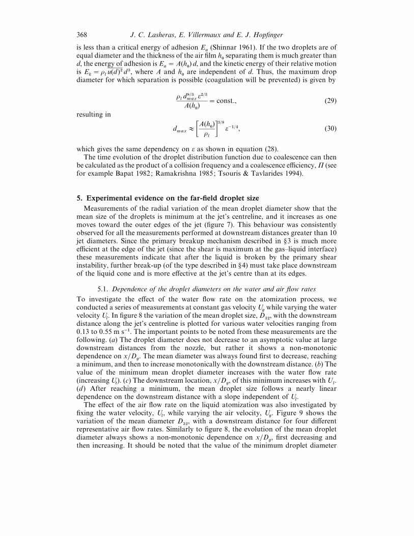
368 J. C. Lasheras, E. Villermaux and E. J. Hopfinger
is less than a critical energy of adhesion Ea
(Shinnar 1961). If the two droplets are ofequal diameter and the thickness of the air film h
!separating them is much greater than
d, the energy of adhesion is Ea¯A(h
!) d, and the kinetic energy of their relative motion
is Ek¯ ρ
lu(d )# d $, where A and h
!are independent of d. Thus, the maximum drop
diameter for which separation is possible (coagulation will be prevented) is given by
ρld)/$max
ε#/$
A(h!)
¯ const., (29)
resulting in
dmax
E 9A(h!)
ρl
:$/) ε−"/%, (30)
which gives the same dependency on ε as shown in equation (28).The time evolution of the droplet distribution function due to coalescence can then
be calculated as the product of a collision frequency and a coalescence efficiency, Π (seefor example Bapat 1982; Ramakrishna 1985; Tsouris & Tavlarides 1994).
5. Experimental evidence on the far-field droplet size
Measurements of the radial variation of the mean droplet diameter show that themean size of the droplets is minimum at the jet’s centreline, and it increases as onemoves toward the outer edges of the jet (figure 7). This behaviour was consistentlyobserved for all the measurements performed at downstream distances greater than 10jet diameters. Since the primary breakup mechanism described in §3 is much moreefficient at the edge of the jet (since the shear is maximum at the gas–liquid interface)these measurements indicate that after the liquid is broken by the primary shearinstability, further break-up (of the type described in §4) must take place downstreamof the liquid cone and is more effective at the jet’s centre than at its edges.
5.1. Dependence of the droplet diameters on the water and air flow rates
To investigate the effect of the water flow rate on the atomization process, weconducted a series of measurements at constant gas velocity U
gwhile varying the water
velocity Ul. In figure 8 the variation of the mean droplet size, D
$#, with the downstream
distance along the jet’s centreline is plotted for various water velocities ranging from0.13 to 0.55 m s−". The important points to be noted from these measurements are thefollowing. (a) The droplet diameter does not decrease to an asymptotic value at largedownstream distances from the nozzle, but rather it shows a non-monotonicdependence on x}D
g. The mean diameter was always found first to decrease, reaching
a minimum, and then to increase monotonically with the downstream distance. (b) Thevalue of the minimum mean droplet diameter increases with the water flow rate(increasing U
t). (c) The downstream location, x}D
g, of this minimum increases with U
l.
(d ) After reaching a minimum, the mean droplet size follows a nearly lineardependence on the downstream distance with a slope independent of U
l.
The effect of the air flow rate on the liquid atomization was also investigated byfixing the water velocity, U
l, while varying the air velocity, U
g. Figure 9 shows the
variation of the mean diameter D$#
, with a downstream distance for four differentrepresentative air flow rates. Similarly to figure 8, the evolution of the mean dropletdiameter always shows a non-monotonic dependence on x}D
g, first decreasing and
then increasing. It should be noted that the value of the minimum droplet diameter

Break-up and atomization of a round water jet 369
90
80
70
60
50
40–1 0 1 2 3 4 5 6 7
r/Dg
D32 (ím)
F 7. Radial variation of the Sauter mean diameter (D$#
) at 30 diameters downstream of thenozzle’s exit. At the outer edges of the jet (r}D
g" 3) the droplet size increases to up to 50% above
the centreline value. Ul¯ 0.23 m s−", U
g¯ 126 m s−".
90
80
70
60
50
40
300 20 40 60 80 100
x/Dg
D32 (ím)
Ul = 0.13 m s–1
Ul = 0.2 m s–1
Ul = 0.31 m s–1
Ul = 0.43 m s–1
Ul = 0.55 m s–1
F 8. Downstream variation of the Sauter mean diameter (D$#
) measured at the jet’scentreline, U
g¯ 140 m s−" and U
l¯ 0.13, 0.20, 0.31, 0.43 and 0.55 m s−".
55
50
45
40
350 10 20 30 40 50
x/Dg
D32 (ím)
Ug = 140 m s
–1
Ug = 133 m s
–1
Ug = 126 m s
–1
Ug = 119 m s
–1
F 9. Downstream variation of the Sauter mean diameter (D$#
) measured at the jet’scentreline. U
l¯ 0.13 m s−", and U
g¯ 119, 126, 133 and 140 m s−".

370 J. C. Lasheras, E. Villermaux and E. J. Hopfinger
Coalescence Break-up
d
åcrit
å
å–2/5
å–1/4
F 10. Equilibrium maximum droplet diameter d as a function of the dissipation rate ofturbulent kinetic energy of the air. Note that for ε! ε
critthe maximum diameter is determined by
coalescence while in regions where ε" εcrit
it is determined by breakup.
decreases with the air flow rate (increasing Ug), while the location of the minimum
decreases with Ug. After the minimum, the mean drop size also increases linearly with
x}Dg.
The existence of two regions of the spray in which the mean droplet diameter exhibitswell-differentiated behaviour is evidence of the competing contributions of the differentterms in equation (20) to the changes in the steady-state value of the dropletdistribution function n(d,x).
To illustrate the nature of these two regions, let us for the moment ignore thepossible contributions of n¡
x[�a to the changes in n, and assume that the evolution of
the size distribution of droplets depends only on the simultaneous occurrence of break-up and coalescence, Q
band Q
c(we will discuss the effect of the acceleration term later).
Then,�a [¡
xn¯Q
bQ
c. (31)
Owing to the large Re of our experiments, the jet’s turbulence closely satisfies theconditions of local isotropy at its centreline. Thus, to a first approximation, assumingthat the droplets stay long enough in a region of sufficiently large turbulent kineticenergy, the maximum droplet size that will withstand break-up is d
maxE ε−#/&
(equation (25)). Similarly, the droplet size above which coalescence will be unlikely tooccur is d
maxE ε−"/% (equation (30)). Since both the break-up and coalescence processes
are determined only by the dissipation rate of the turbulent kinetic energy, ε, throughdifferent power exponents, it easily follows that depending on the local value of ε, oneprocess will dominate the other. As the energy dissipation decreases downstream, in theregion of high values of ε (near field, small x}D) break-up is dominant and the dropletsize is determined by equation (25), while in regions of small dissipation (far field, largex}D
g) it will be controlled by the coalescence process, and the size is given by equation
(30) (Shinnar 1961) (see figure 10). In the following we will refer to each of these regionsas the break-up region (descending portion in figures 8 and 9), and the coalescenceregion (ascending portion in figures 8 and 9).
The droplet break-up region
As discussed above in relation to the radial measurements shown in figure 7, thelumps of liquid pinched off from the central liquid cone must undergo secondarybreak-up by the turbulent fluctuations of the continuous phase. As shown above, if theresidence time of the liquid in the highly dissipative region of the turbulent jet is long

Break-up and atomization of a round water jet 371
enough for the break-up to be completed, a local equilibrium will always be reached.Thus, one will conclude that, since ε is maximum near the end of the potential core, theminimum in figures 8 and 9 should always be at a location x}D
gE 5–8 (increasing
as the air}water momentum ratio decreases). However, as is apparent from the aboveexperimental results, this is never the case ; and the minimum always occurs at distancesx}D
gE 15–20, much further downstream from the nozzle. From this fact alone, it is
obvious that although the dissipation rate is higher near the nozzle’s exit, the liquidresidence time is shorter than that needed for break-up. Equilibrium will then bereached at a critical distance downstream from the nozzle, x
crit, where the break-up
time of the droplet equals its residence time. Assuming that the droplet break-up timeis of the order of the eddy turnover time t
b¯ d
max}(u(d )#)"/#, introducing equation (24),
we gettbE ε−"/$ d #/$
max. (32)
On the other hand, the liquid residence time can be estimated as
tr¯&x dξ
U(ξ ), (33)
where U(ξ ) is the mean velocity of the liquid drops along the jet’s centreline. Since U(ξ )is of the order of the mean velocity of the jet along its centreline, it is reasonable toassume that U(ξ )EU
g}xβ with β being a constant of order 1 which depends on the
water to air mass flow rate (β¯ 1 if m¯ 0). Integrating equation (33), we get
trE
x(β+")
(β1)Ug
. (34)
Combining (32) and (33), the critical equilibrium length can then be estimated as
xcrit
EU−(β+")γ ε−"/$(β+") d#/$(
β+")max
, (35)
and introducing equation (25), we get
xcrit
EU"/(β+")
gε−$/&(β+") (σ}ρ
g)#/&(β+"). (36)
What remains now is to estimate the turbulent dissipation rate along the jet’scentreline. It is well known that in a single-phase jet, the dissipation rate is proportionalto the initial kinetic energy of the jet per unit mass per unit time, U$
!}D
g, where U
!is
the initial jet velocity and Dg
is the diameter of the nozzle. It is then reasonable topostulate that in our two-phase flow case, the dissipation rate in the gas should nowbe proportional to the total initial flux of kinetic energy (contained mainly in the gas)per unit total mass (gas plus liquid). Thus,
εEU$
g
(1ρlUl}(ρ
gUg))ω D
g
, (37)
where ω depends on the liquid to air mass flow rate, m, and will be determinedexperimentally. Combining equations (36) and (37), and taking β¯ 0†, we get
xcrit
¯U−%/&g 9 1
(1ρlUl}(ρ
gUg)ω D
g
:−$/& 0σρg
1#/&. (38)
† In our two-phase flow jet, the mean centreline velocity is approximately constant for thefirst five to eight diameters, at which point our measurements show a decrease U(x)EU
g}x β, with
0.2%β% 0.6, and the value of β increasing with M. Thus, as a conservative estimate, we takeβ¯ 0.

372 J. C. Lasheras, E. Villermaux and E. J. Hopfinger
35
30
25
20
150.03 0.04 0.05
40
35
30
25
20
150.03 0.04 0.05
(b)
(a)
(x/D
g)cr
itUg
–4/5(1+ò1U1/ògUg)3/5
Ug–4/5(1+ò1U1/ògUg)
3/5
(x/D
g)cr
it
F 11. (a) Comparison of the measured downstream location of the droplet break-upequilibrium point x
critin figure 8 with the prediction given by equation (38) (solid line). (b)
Comparison of the measured downstream location of the droplet break-up equilibrium point xcrit
infigure 9 with the prediction given by equation (38) (solid line).
Equation (38) shows a dependence of xcrit
on Uland U
gconsistent with that observed
experimentally, i.e. the downstream location of the minimum (i.e. the location at whichequilibrium is reached, x¯x
crit) increases with U
lwhile it decreases with U
g. Figure
11(a, b) shows the measured values of xcrit
for all the Uland U
gcorresponding to figures
8 and 9. Observe that the dependence predicted by equation (38) is consistent with theexperimental results. Furthermore, using (38) as a correlation of the experimental data,we can estimate ω to be approximately equal to 1.
The value of the mean diameter at the equilibrium (minimum in figures 8 and 9) isthen calculated by combining equations (25) and (37) to give
dmax
E 9 σ
(Wet)c
:$/& 9 U$g
(1ρlUl(ρ
gUg)ω D
g
:−#/&. (39)
Since the drop size predicted by the secondary atomization argument is the maximumdrop size, we have selected the D
*!(the diameter for which 90% of the total liquid
volume is in droplets of smaller diameters) as the relevant parameter to measure. The

Break-up and atomization of a round water jet 373
110
100
90
80
70
600.003 0.004 0.005
D90
(ím
)
[Ug3}(1+ò1U1}ògUg)]
–2/5
F 12. Dependence of the measured maximum droplet diameter at the equilibrium point (D*!
)on the flux of total kinetic energy of the air jet per unit total mass of the system. U
g¯ 140 m s−" and
Ul¯ 0.13, 0.20, 0.31, 0.43 and 0.55 m s−".
100
80
60
40
0.0034 0.0038 0.0042
D32
and
D90
at (
x/D
g)cr
it
D32
D90
[Ug3}(1+ò1U1}ògUg)]
–2/5
F 13. Dependence of the measured maximum droplet diameter at the equilibrium point (D*!
)on the flux of total kinetic energy of the air jet per unit total mass of the system. U
l¯ 0.13 m s−", and
Ug¯ 119, 126, 133 and 140 m s−".
dependence of D*!
measured at the minimum on Uland U
gis shown in figures 12 and
13. Note that, consistent with the predicted dependence given above, in both cases D*!
is found to correlate well with [U$g}(1ρ
lUl}(ρ
gUg))]−#/& where ω in equation (38) is
also found to be 1.
The droplet coalescence region
Downstream of xcrit
the turbulent kinetic energy of the air can no longer providesufficient pressure deformation forces to overcome the confinement by the surfacetension. From this location onward, droplet coalescence, acceleration, and evaporation(although, as discussed before, negligible in our case) will determine the mean dropsize.
In the coalescence region, located downstream of the minimum in figures 8 and 9,the most probable drop size above which coalescence will be prevented by theturbulence is given by equation (30). Introducing the value of the estimated turbulentdissipation rate, and assuming that in the far field of the jet decays as (x}D
g)−% similarly

374 J. C. Lasheras, E. Villermaux and E. J. Hopfinger
(a) (b)15
10
5
0
–5
–10
(c)15
10
5
0
–5
–100 20 40 60 80 100
(d)
0 20 40 60 80 100
x/Dgx/Dg
Udi
–U
g (m
s–1
)U
di –
Ug
(m s
–1)
Ud1-U
g
Ud5-U
g
Ud4-U
g
Ud3-U
g
Ud2-U
g
F 14. Mean slip velocity between the droplets and the surrounding air measured at the jet’scentreline. The droplet sizes have been classified in six size bins : D
"for sizes between 5 and 18 µm;
D#for sizes between 18 and 36 µm, D
$for sizes between 36 and 75 µm, D
%for sizes between 75 and
110 µm, and D&for droplets greater than 110 µm. The gas has been measured by the droplets in the
size bin with droplets smaller than 5 µm. (a) Ug¯ 140 m s−" and U
l¯ 0.2 m s−", (b) U
g¯ 140 m s−" and
Ul¯ 0.31 m s−", (c) U
g¯ 140 m s−" and U
l¯ 0.41 m s−", (d ) U
g¯ 140 m s−" and U
l¯ 0.53 m s−".
to the decay observed in one-phase jets, Friehe, Van Atta & Gibson (1977) (anassumption which will lose validity for very large M ) we get
(dmax
)coalescence
E 9 U$g
(1ρlUl}(ρ
gUg))α D
g
:−"/%0 x
Dg
1 , (40)
which shows that in the coalescence region the droplet diameter grows linearly with thedownstream distance, in agreement with the measured evolution given in figures 8 and9. Note also that the local coalescence equilibrium assumption made above gives adependence of the slope on U
land U
g. However, this dependence is not apparent in the
experimentally observed evolution (figures 8 and 9), where it appears that the slopes areindependent of U
land U
g.
5.2. Effect of the droplet acceleration
Let us now turn our attention to the analysis of the possible contribution of ®n¡x[�a
to the downstream variation of n. To estimate the acceleration of the droplets ¡x[�a let
us consider one droplet in isolation. To a first approximation, the droplet inertia isbalanced by the viscous drag
�ad�adx
Eµ#(�a ®U
g)
ρ"d #
, (41)

Break-up and atomization of a round water jet 375
0
Vl – Vg
D1
D2
D3
D4
x/D
Region IIIRegion IIRegion I
F 15. Region I – liquid acceleration; Region II – acceleration of large size dropletscoexisting with deceleration of small ones ; Region II – droplet deceleration.
where, for simplicity, we have assumed Stokes’ drag law, and neglected unsteady termssuch as added mass, Basset, and effects. The droplet acceleration is inverselyproportional to the square of its diameter, and the relaxation length for the droplet tobe accelerated to the gas velocity, U
g, is then
xaccel
EρlUgd #
µg
. (42)
Figure 14 shows the measured values of �a for four representative cases. Thesemeasurements were obtained by discretizing the droplet distribution function into sixdroplet sizes bins, with the one corresponding to d! 3 µm used to measure the gasvelocity. Note that as one would expect, the downstream evolution of the mean dropletvelocities is made up of three regions (see figure 15).
Region I. In the near field, all the droplets regardless of their size are moving atvelocities lower than that of the gas, and are being accelerated (positive acceleration)by the viscous and pressure forces F. Since for each drop, its relaxation length isproportional to d #, the smaller droplets will begin to move faster than the larger ones.Therefore, since assuming the absence of break-up or coalescence �a [¡
xn¯®n¡
x[�a , it
follows that the effect of the initial acceleration in the near field is to increase the meandroplet size (observe that the smaller droplets move faster than the larger ones, and themean size increases). Since this result is in direct opposition to the experimentallyobserved decay in the size, it can be considered as a corroboration of the assumptionmade above that the size decay in the first region in figures 8 and 9 is determined bybreak-up and not by acceleration effects.
Region II. After the droplets are accelerated to the gas velocity, their inertia leadsto a velocity overshooting region whereby the larger droplets pass the gas while thesmaller ones quickly begin to relax again to reach the gas velocity. Thus, in this secondregion, the term ¡
x[�a will lead to a decrease in the mean droplet size. The extent of this
second region can be estimated by introducing equations (25) and (37) into (42) to give
xaccel
EρlUl
µg
9 σ
(Wet)c
:'/& 9 U$g
(1ρlUl}(ρ
gUg))mD
g
:−%/&, (43)
376 J. C. Lasheras, E. Villermaux and E. J. Hopfinger
a result again consistent with the experimentally observed dependencies of the air andwater velocities.
Region III. After the maximum drop size has reached a maximum velocity, alldroplets regardless of their size will decelerate leading to an increase in the meandroplet size. (Note that ¡
x[�a is always negative and larger for the smaller droplets.)
Thus, the effect of the droplet acceleration leads to the same dependence of the meansize as did the coalescence effects. However, since the magnitude of ¡
x[�a is very small,
this contribution is most likely small compared to the coalescence effects.
5.3. Effect of the turbulent dispersion and droplet e�aporation
Implicit in our discussion of equation (20), and in particular in the analysis of the terms�a [¡
xn and n¡
x[�a in the preceding section, was that the spray behaves as a quasi-one-
dimensional flow, i.e. we accounted only for the transport effects resulting from theaxial motion of the spray. However, as was shown in figures 2, 3 and 6, the lateralspreading of the jet is dominated by the presence of a large-scale coherent eddystructure. These eddies are known to dominate the turbulent diffusion of the dropletacross the spray, whereby the droplets are dispersed laterally, according to their size(Lazaro & Lasheras 1992a, b ; Longmire & Eaton 1992, and Kiger & Lasheras 1995).
This large-scale lateral transport results in two main effects. The first one is toproduce a downstream increase in the mean droplet size. Recall from figure 7 that, nearthe nozzle, the mean droplet size is considerably larger at the edges of the spray thanon its centreline. As one moves downstream, these large coherent eddies, with scalescomparable to the radial thickness of the spray, will ultimately tend to homogenize themean size of the droplets across the spray. This is an effect consistent with ourmeasurements of the salter mean diameter, which shows that as one moves downstreamdistances larger than 80 to 100 nozzle diameters, the mean size of the droplets becomesuniform across the spray.
The second effect of the large-scale eddies is to entrain ambient air into the sprayacross distances comparable to the spray’s radius. Since the entrained air is notsaturated with water vapour, this will contribute to some evaporation of the waterdroplets. Thus, at some distance downstream from the nozzle, our assumption ofnegligible evaporation effects will break down, and the term involving R in equation(16) should be retained in the analysis. However, notice that the evaporation effects willcontribute in the opposite way to the measured increase of the mean diameter withdownstream distance (figures 8 and 9), indicating that the assumption of negligibleevaporation is most likely a reasonable one.
6. Conclusions
The atomization of a liquid jet by a high-momentum turbulent annular jet has beenshown to be the result of a dual process. In the near field, the break-up process isdominated by the shedding of liquid sheets or ligaments. In the far field, a secondarybreakup process may also take place whereby liquid lumps pinched off from the jet aresplit by the turbulent stresses of the air jets. The measurements of the sheddingfrequency in the near field are shown to be qualitatively described by the simplephenomenological model. For initially laminar water jets, it was found that thisfrequency increases proportionally to the square of the gas velocity. However, in thecase of an initially turbulent water jet, it was found to exhibit a linear increase with theair velocity. An entrainment model was developed to predict qualitatively the liquidintact length. It was shown that in the case of large initial aerodynamic Weber numbers

Break-up and atomization of a round water jet 377
and high gas Reynolds numbers, the liquid intact length depends mainly on the air towater momentum ratio. This result underscores the relevance of the momentum ratioto the breakup process in this type of air blast atomizer.
The far field of the spray jet was found to be characterized by two well-definedregions: an initial region where the mean droplet size measured at the jet’s centrelinemonotonically decreases with the downstream distance, followed by a second regionwhere the droplet’s diameter increases with the downstream distance. The role of thesecondary droplet break-up in the size distribution measured in these regions was alsoinvestigated, and an attempt was made to use the classical concepts of local isotropy,first proposed by Kolmogorov, to qualitatively explain the observed downstreamvariation of the droplet’s size and its dependence on the water and air velocities.
Simplified models of the effect of the turbulent energy dissipation in the gas on thebreak-up and coalescence of the droplets were developed and compared to theexperimental evidence resulting in good, qualitative agreement. The first region wasshown to be dominated by the secondary break-up process. Both the values of theminimum droplet size (reached at the equilibrium point), and the downstream locationof this equilibrium point were found to be well predicted by the model. The locationof the minimum droplet size was found to decrease with the gas’s velocity, while itincreased with the liquid’s velocity. Correlations of the droplet size measurementsmade based on the local isotropy model indicate that the dissipation rate of theturbulence in the air jet is approximately proportional to the total kinetic energy flux(primarily contained in the air jet) per unit total mass (airwater). The increase in thedroplet size observed in the second region was found to be the result of dropletcoalescence and droplet deceleration, with the latter playing a minor role. A simplecoalescence efficiency model based on the dissipation rate appears to be in goodqualitative agreement with the observed increase of the mean droplet diameter withdownstream distance, and the dependence of the mean droplet diameter on water andliquid velocity.
Support for this work was provided by grants from United TechnologiesCorporation and the Societe Europeenne de Propulsion. The authors are grateful forassistance provided by Professor Kenneth Kiger, Ms Monica Orski, and Mr CarlosMartinez in various stages of the experimentation. Valuable discussions withDr Christophe Clanet are also greatly appreciated.
REFERENCES
A, M. 1968 Mean drop size resulting from the injection of a liquid jet into a high-speed gasstream. AIAA J. 6, 1143–1147.
B, J. & B, J. 1993 Drop break-up and intermittent turbulence. J. Chem. Engng Japan26, 738–741.
B, P. M. 1982 Mass transfer in liquid–liquid continuous flow stirred tank reactor. PhDdissertation. Illinois Institute of Technology, Chicago.
B, R. J. 1972 Space storable propellant performance program. Coaxial injectors char-acterization. NASA CR-120936.
C, S. 1961 Hydrodynamic and Hydromagnetic Stability. Dover.
C, P. H. 1940 Splitting in dispersion processes. Proc. R. Acad Sci. Amsterdam 43, 852–858.
D, P. E. 1986 Two-dimensional shear layer entrainment. AIAA J. 24, 1791–1796.
D, N. & J, W. R. 1963 The aerodynamic instability and disintegration of viscousliquid sheets. Chem. Engng Sci. 18, 203–214.

378 J. C. Lasheras, E. Villermaux and E. J. Hopfinger
E, C., H, Y. & W, J. H. 1995 Breakup phenomena in coaxial airblastatomizers. Proc. R. Soc. Lond. A 451, 189–229.
E, H., C, N. & F, Z. 1991 Coaxial atomiser liquid intact lengths. Phys. Fluids A3, 303–308.
F, Z. & C, N. 1992 Morphological classification of disintegration of round jets in acoaxial airstream. Atomization and Sprays 2, 137–153.
F, C. A., V A, C. W. & G, C. H. 1972 Jet turbulence: dissipation rate measurementsand correlations. In Proc. AGARD Conf. on Turbulent Shear Flows, London September 1971.AGARD CP 93, 1972.
G, H. 1985 Pneumatic atomization with coaxial injectors. NAL-TR-888T, N 86-27595.
H, A. R., D, E. G. & A, H. S. 1963 Shock tube investigation of the break-up ofdrops by air blast. Phys Fluids 6, 1070–1080.
H, Y. & W, J. H. 1994 The characteristics of sprays produced by coaxial airblastatomizers. J. Propulsion Power 10, 453–460.
H, J. O. 1955 Fundamentals of the hydrodynamic mechanism of splitting in dispersionprocesses. AIChE J. 1, 289–295.
H, E. & L, J. C. 1994 Break-up of a water jet in a high velocity coflowing air. InProc. Sixth Intl Conf. on Liquid Atomization and Spray Systems (ed. A. J. Yule & C. Dumouche),pp. 110–117. Begell House.
H, J. W. & T, J. J. 1977 Waves on water jets. J. Fluid Mech. 83, 119–127.
I, R. D. 1992 Effect of gas mass flux on cryogenic liquid break-up. Cryogenics 32, 191–193.
J, G. V. & D, G. A. 1971 Coalescence of liquid droplets and liquid dispersion. InRecent Ad�ances in Liquid–Liquid Extraction (ed. C. Hanson), p. 495. Pergamon.
K, F. X., L, J., V, A., V, D. & Z, S. 1994 Direct numerical simulationof interface breakup and atomization. In Proc. Sixth Intl Conf. on Liquid Atomization and SpraySystems (ed. A. J. Yule & C. Dumouche). Begell House.
K, K. & L, J. C. 1995 Effect of vortex pairing on particle dispersion and kinetic energytransfer in two-phase turbulent shear layers. J. Fluid Mech. 303, 149–165.
K, A. N. 1949 On the disintegration of drops by turbulent flows. Dokl. Akad. Nauk.SSSR 66, 825–828.
L, W. R. 1951 Shatter of drops in stream of air. Ind. Engng Chem. 43, 1312–1317.
L, L. D. & L, E. M. 1959 Course of Theoretical Physics, Vol. 6. Fluid Mechanics.Pergamon.
L, B. J. & L, J. C. 1992a Particle dispersion in the developing free shear layer. Part1. The unforced flow. J. Fluid Mech. 235, 143–178.
L, B. J. & L, J. C. 1992b Particle dispersion in the developing free shear layer. Part2. The forced flow. J. Fluid Mech. 235, 179–221.
L, A. H. 1989 Atomization and Sprays. Hemisphere.
L, E. & E, J. 1992 Structure of a particle laden round jet. J. Fluid Mech. 236, 217–257.
M, W. O. H. 1993 Zur koaxialen flussgkeitszerstanburg im hinblick auf die treibstoff-aufbereitung in raketen-triebwerken. DLR-FB 93-09. Germany.
N, G. E. & T, Y. 1939 Experiments on the atomization of liquids by means of airstreams, parts III and IV. Trans. Soc. Mech. Engrs Japan 5 (18), 63–75.
P, M. & E, C. A. 1987 Use of breakup time and velocity history data to predict themaximum size of stable fragments for acceleration induced breakup of a liquid drop. Intl J.Multiphase Flows 13, 741–757.
R, L 1878 On the instabilities of jets. Proc. Lond. Math. Soc. 10, 4–13.
R, L. 1997 Instabilite! et entrainement a' l’interface d’une couche de me! lange liquide-gaz.PhD thesis, Institute National Polytechnique de Grenoble, France.
R, L., V, E., L, J. C. & H, E. J. 1997 Primary instability inliquid–gas shear layers. In Proc. Symp. on Turbulent Shear Flows 11, Vol. 3, pp. 1–5.
R, L., V, E. & H, E. J. 1988 Primary instability of a plane liquid–gasshear layer. J. Fluid Mech. (submitted).
R, D. 1985 The status of population balances. Re�. Chem. Engng 3, 49.

Break-up and atomization of a round water jet 379
R, H., V, E. & H, E. J. 1997 Flow regimes of large-velocity-ratio coaxialjets. J. Fluid Mech. 345, 357–381.
R, A. A. & L, A. H. 1975 The influence of air and liquid properties on air blastatomisation. Trans. ASME, 316–320.
S, H. 1987 Boundary Layer Theory, 7th Edn. McGraw-Hill.
S, M. & P, S. H. 1973 The splitting of drops and bubbles by turbulent fluid flows. J. Trans.ASME Fluids Engng 95, 53–60.
S, R. 1961 On the behaviour of liquid dispersions in mixing vessels. J. Fluid Mech. 10,259–275.
S, G. P. 1992 Rocket Propulsion Elements. Wiley and Sons.
T, G. I. 1934 The formation of emulsion in definable field of flow. Proc. R. Soc. Lond. A 146,501.
T, C. & T, L. L. 1994 Breakage and coalescence models for drops in turbulentdispersions. AIChE J. 40, 395–406.
V, E. 1995 Fast bimolecular reactions in high Reynolds number turbulence: structure ofthe reactive interface and surface of reaction. In Ad�ances in Turbulence V (ed. R. Benzi),pp. 529–533. Kluwer.
V, E. & H, E. J. 1994a Periodically arranged co-flowing jets. J. Fluid Mech. 263,63–92.
V, E. & H, E. J. 1994b Self-sustained oscillations of a confined jet : a case studyfor the non-linear delayed saturation model. Physica D 72, 230–243.
V, E., R, H. & H, E. J. 1994 Breakup re! gimes and self-sustainedoscillations in coaxial jets. Meccanica 29, 393–401.
W, C. 1931 Zum zerfall eines flussigkeitstrahles (on the disruption of liquid jets). Z. Angew.Math. Mech., vol. II, no. 2.
W, A. & T, K. 1987 Experimental investigations of liquid droplet breakup in a gasstream. Rep. Inst. High Speed Mech. 53 (382) 2–93.
W, F. A. 1985 Combustion Theory, 2nd Edn. The Benjamin}Cummings PublishingCompany.
Z, S., J L, & S, S. 1995 Two-dimensional Navier–Stokes simulation of deformationand breakup of liquid patches. Phys. Re�. Lett. 75, 244–247.