breast mr imaging and quality control - amos...
TRANSCRIPT

Breast MR Imaging and
Quality Control
Donna M. Reeve, MS, DABR, DABMP
Department of Imaging Physics

Educational Objectives
1. Provide an overview of breast MR imaging and
MR-guided biopsy procedures.
2. Describe breast MR image quality criteria and
protocol optimization.
3. Discuss the components of a breast MRI quality
control program.

Breast MR Imaging
Screening for patients at higher risk for breast
cancer due to family history or the presence of
genetic markers.
Detect malignancies not visible on mammography,
ultrasound
Determine the extent of disease
Monitor response to treatment
Detect implant rupture

Breast MR Imaging Systems
Dedicated breast MRI systems:
Whole body MRI systems:
~ dedicated tables with integrated breast coils
~ detachable table-top breast coils
www.sentinellemedical.com/products.html www.invivocorp.com/coils/
www.auroramri.com
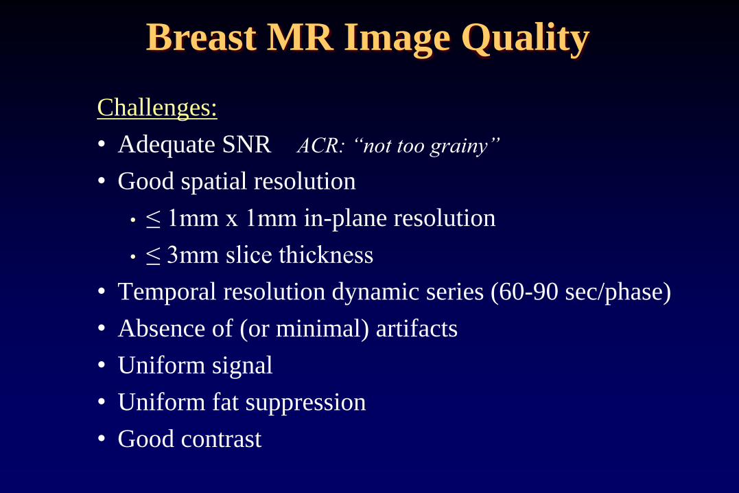
Challenges:
• Adequate SNR ACR: “not too grainy”
• Good spatial resolution
• ≤ 1mm x 1mm in-plane resolution
• ≤ 3mm slice thickness
• Temporal resolution dynamic series (60-90 sec/phase)
• Absence of (or minimal) artifacts
• Uniform signal
• Uniform fat suppression
• Good contrast
Breast MR Image Quality
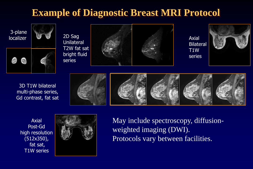
Example of Diagnostic Breast MRI Protocol
3D T1W bilateral multi-phase series, Gd contrast, fat sat
3-plane localizer Axial
Bilateral T1W series
2D Sag Unilateral T2W fat sat bright fluid series
Axial Post-Gd
high resolution (512x350),
fat sat, T1W series
May include spectroscopy, diffusion-
weighted imaging (DWI).
Protocols vary between facilities.
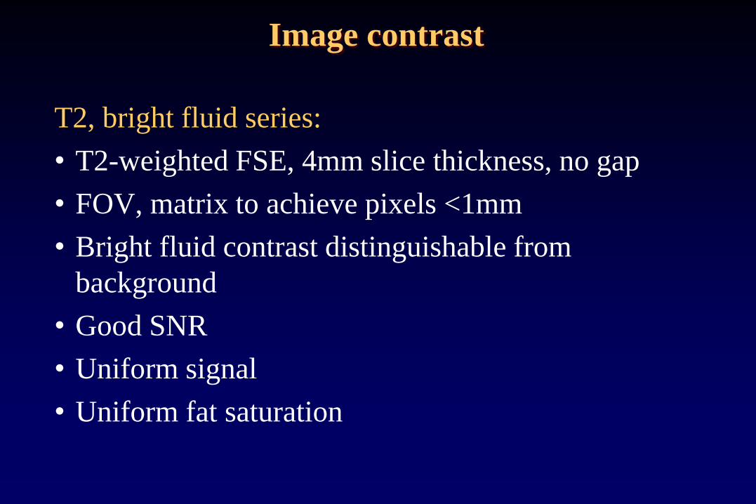
T2, bright fluid series:
• T2-weighted FSE, 4mm slice thickness, no gap
• FOV, matrix to achieve pixels <1mm
• Bright fluid contrast distinguishable from
background
• Good SNR
• Uniform signal
• Uniform fat saturation
Image contrast

T2W bright fluid series:
Bright fluid contrast
Fat saturation fairly uniform
Clinical example
GE 1.5T HDXt
2D T2W, sagittal
FSE, ETL 17, fat sat
TR/TE 4950/89 ms
256x192, NEX 2
FOV 220mm,
4.0mm/0 gap
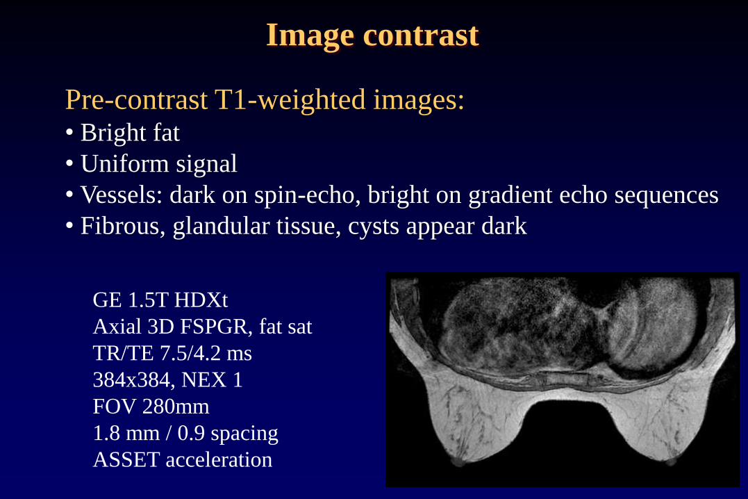
Pre-contrast T1-weighted images: • Bright fat
• Uniform signal
• Vessels: dark on spin-echo, bright on gradient echo sequences
• Fibrous, glandular tissue, cysts appear dark
GE 1.5T HDXt
Axial 3D FSPGR, fat sat
TR/TE 7.5/4.2 ms
384x384, NEX 1
FOV 280mm
1.8 mm / 0.9 spacing
ASSET acceleration
Image contrast

Fat Saturation Methods
• Frequency-selective fat saturation (fat sat,
chem sat) dependent on good magnetic field
homogeneity
• Subtraction of T1W co-registered pre- and
post-contrast images
• Dixon methods
• Inversion-recovery based sequences (STIR)

Frequency-selective Fat Saturation
• Frequency-selective fat or silicone saturation is routinely
used in breast imaging. Frequency of saturation pulse must
match resonant frequency of fat/silicone.
• Selection of resonant peak usually automated, but may
require manual adjustment Technologist training
essential.
• Uniform saturation dependent on homogeneity of B0 field
within the imaged volume:
• challenge (breasts off isocenter)
• shimming is important

Fat/silicone saturation - peak selection
water
fat
silicone
~220 Hz ~100 Hz 1.5T
Increasing frequency
~200 Hz 3T (fat-water separation 3.5 ppm)
~440 Hz
Effective chemically-
selective fat or silicone
saturation depends on
accurate peak selection.
GE: center on water, saturates fat signal at -220Hz (1.5T)

Composition of breast tissue
Glandular tissue Silicone Adipose tissue
Composition of breast tissue (adipose/glandular/silicone) determines
appearance of spectrum. Peaks may not be distinct. Selecting the
correct peak to achieve fat or silicone saturation can be challenging.

T2-weighted FSE, fat sat failure
Difference in center frequency 440 Hz (3.5 ppm) equal to 3T difference in
resonant frequency between fat-water. Centered on fat peak fat sat
failed to suppress fat signal.
Left breast Right breast
CF 128,173,640 Hz CF 128,173,200 Hz

3D T1 post-contrast dynamic, fat sat
Left breast Right breast
Center frequency = 128,173,593 Hz
Good fat saturation achieved on both sides

Saturation failure
T2W fast spin-echo TR =3500ms / TE =86 ms echo train length = 8 122 Hz/pixel bandwidth 256x256 matrix, 200 mm FOV 1 average fat sat
• Bandwidth of the sat pulse
centered on fat sufficient to
saturate both fat and silicone
signal – both appear dark.
• Incomplete saturation of fat
and/or silicone can occur in
regions with large static
magnetic field
inhomogeneties.
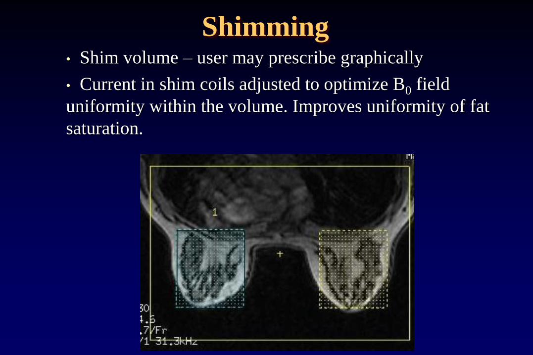
Shimming • Shim volume – user may prescribe graphically
• Current in shim coils adjusted to optimize B0 field
uniformity within the volume. Improves uniformity of fat
saturation.

AuroraSUPERSHIMTM
One vendor’s shim coil system is designed to improve fat
suppression in breast MR imaging
typical MRI Aurora MRI
Oval shape and positioned more anterior so that bilateral breast
tissue is centered within shim volume. http://www.auroramri.com/mri/index.shtml
Shimming
Image Contrast
Post-Gd contrast T1-weighted images
• Gadolinium contrast agent shortens the T1 relative
to adjacent tissues.
• Lesions that uptake contrast agent appear bright on
T1-W images
• Non-malignant pathologies may also appear bright
• Fat suppression necessary to differentiate between
bright fat and enhancing tissues.

T1W DCE Multi-phase series
Pre-contrast
Early/first phase Phase 1
Phase 2
Phase 3
Late/last phase Phase 4
0:00 1:43 3:26 5:09 8:35
Min:Sec
Gd

Dynamic Contrast Enhancement
(DCE)
Kuhl CK, et al. Dynamic breast MR
imaging: are signal intensity time course
data useful for differential diagnosis of
enhancing lesions?
Radiology. 1999 ;211(1):101-110.
Types I, II, III:
- Persistence of
enhancement
- Timing of peak
enhancement,
- Rate of washout

Dynamic Contrast Enhancement
(DCE)
Uptake rate depends on:
• vascular density: tends to be higher in tumors
• Wash out rate:
Faster rate in malignancies
Slower in benign lesions
Also affected by
• Hormone replacement
• Timing within menstrual cycle

T1W Multi-phase series
Subtraction
Subtraction
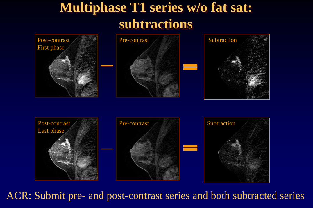
Multiphase T1 series w/o fat sat:
subtractions
ACR: Submit pre- and post-contrast series and both subtracted series
Pre-contrast Post-contrast
First phase
Pre-contrast Post-contrast
Last phase

Potential to improve specificity
Choline (tCho) indicator of cell proliferation
If present, likely malignant
Breast MR Spectroscopy
Bolan, P.J. ISMRM, 2004.

Spatial Resolution: ACR Criteria only apply to pre- and
post-contrast T1-weighted multi-phase series:
• Acquired (not interpolated) thickness must be ≤ 3mm,
>4.0mm will fail.
• 3-4mm: may fail if there are deficiencies in other
categories.
• In-plane resolution must be ≤ 1mm (phase and freq),
>1.2mm will fail, 1.0-1.2mm may fail if deficiencies in
other categories.
• Interslice gap must be ≤ 0mm (i.e. slices either overlap or
are contiguous with no gap), >0mm will fail
Spatial Resolution

Spatial resolution
High contrast spatial resolution requires small voxels:
• Large matrix
• Small FOV
• Thin slices
Trade-offs:
• Longer scan time if phase matrix is increased
• Reduced SNR improve with 3T imaging
= FOV / N Resolution (frequency-encoding direction
= FOV / N Resolution (phase encoding direction)
slice Resolution (slice direction)
Tscan = TR Nave N Acquisition time

Temporal Resolution: ACR criteria apply to T1-
weighted multi-phase series:
• Total time between contrast injection completion and end
of early phase:
≤4min
>5min will fail
1min-5min may fail if other deficiencies
• Total time = time delay + acquisition time of early phase
28
Temporal Resolution

Speed Parameters that improve speed (DCE temporal resolution):
Parameter Trade-off
↓ Repetition time (TR) ↓SNR
↓ Number of scan averages (NSA, NEX) ↓SNR
↓ Phase encode matrix ↓Resolution (in-plane)
↓ Number of 3D slice encodes (thicker slices) ↓Resolution (slice
direction)
Hardware: gradient performance (↑dB/dt) ↑ Cost
Coil: ↑ # of independent phased array elements ↑ Coil cost,
↓ Uniformity
Parallel imaging: ↑Acceleration factor ↓ SNR, potential
artifacts

SNR Potential causes of low SNR:
• Low field strength
• Poor coil connection
• Coil element failure
• Incorrect center frequency selection
• Protocol parameters:
- Small voxels (large matrix,
small FOV, thin slices)
- trade-offs: speed, SNR, resolution
1 0H s ave
samp
FOV FOVSNR N B f
N N

FSE T2W w/ fat sat,
FOV 220mm, 256x192, 4mm
1.5T 3T
FSE T2W w/ fat sat,
FOV 200mm, 320x192, 3mm
3T– trade additional SNR for increased spatial
resolution or faster scan time

Breast MRI Artifacts
Common artifacts in breast MRI
• Motion
• Truncation artifacts
• Out of volume wrap
• Susceptibility artifacts
• Signal non-uniformity
• Poor or non-uniform fat saturation

Motion artifacts Occur in the phase encoding direction. Caused by cardiac
motion, respiration, patient movement. Results in phase
mis-mapping in k-space due the time delay between
phase-encoding and signal readout.
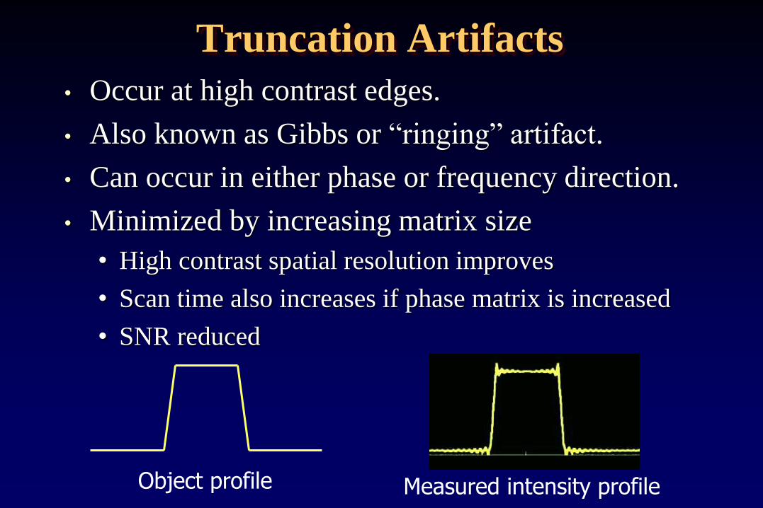
Truncation Artifacts
• Occur at high contrast edges.
• Also known as Gibbs or “ringing” artifact.
• Can occur in either phase or frequency direction.
• Minimized by increasing matrix size
• High contrast spatial resolution improves
• Scan time also increases if phase matrix is increased
• SNR reduced
Object profile Measured intensity profile

Pha
se
Truncation Artifacts
Small ACR phantom in 3T GE 8 channel HD breast array
320x192 matrix 320x320 matrix
Frequency
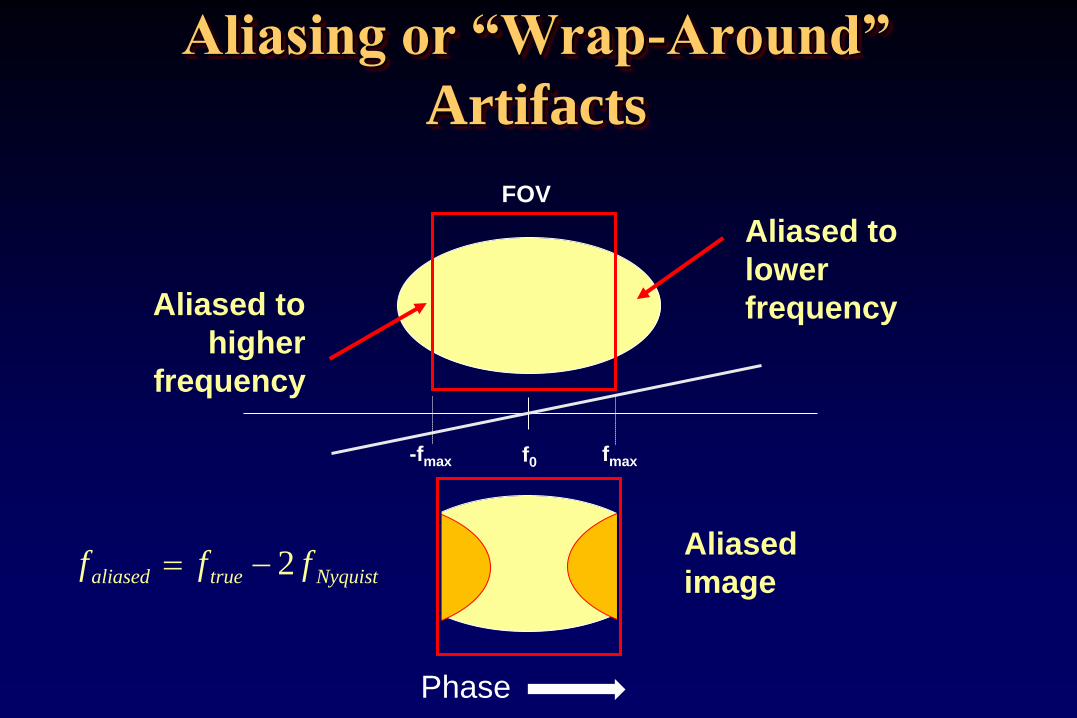
Aliasing or “Wrap-Around”
Artifacts
-fmax fmax f0
FOV
Aliased to
lower
frequency Aliased to
higher
frequency
Aliased
image f f faliased true Nyquist 2
Phase

Aliasing or “Wrap-Around”
Artifacts • Increase FOV to include
anatomy & increase phase-encode
steps to maintain resolution
(trade-off: impacts scan time)
• Swap phase and frequency-
encoding directions : shorter
dimension in phase-encoding
direction. (trade-off: cardiac/
respiratory motion artifacts)
• Use “No phase wrap” or “anti-
aliasing” techniques.
Phase

Peripheral Signal Artifact
(annefact, star artifact)
FSE: Star artifact – bright signal close to
center of 3D images.
FSE: Spine exam using spine phased array
coil .
Phase
Phase
Signal originates in region outside FOV where gradients are
nonlinear. FID from 180 pulses not crushed – aliases back into
image.

Magnetic Susceptibility Artifacts
Metallic objects can cause distortions of the static and
gradient fields, RF fields, or both
Ferromagnetic objects - distort Bo and B1 fields
Non-ferromagnetic metal objects - distort B1 fields
Typical effects are signal voids
and geometric distortions. Most notice-
able on GRE (rather than
SE or FSE). Reduce appearance
with wider receive BW, shorter TE.

Signal uniformity and breast coil design
1.5T Sentinelle coil -
axial image of small
ACR phantom
3T GE HD array -
axial image of small
ACR phantom

Signal Uniformity • Patient position and fit within the coil
• Shape and position of coil elements, how well coil
conforms to breast shape
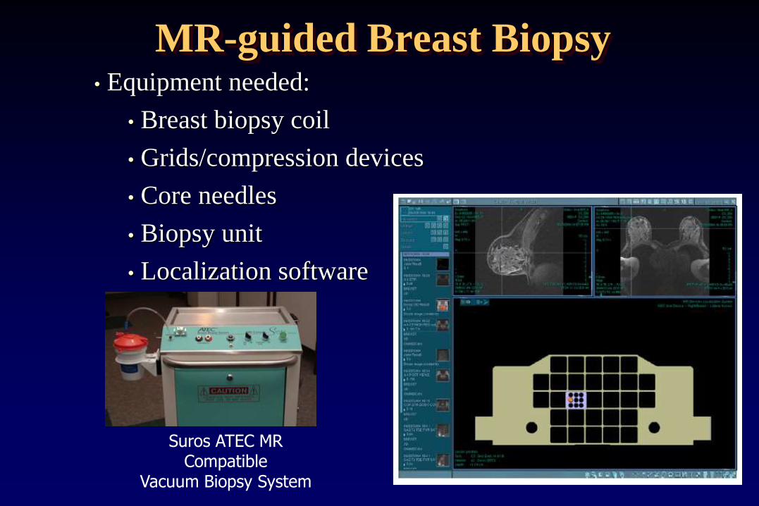
MR-guided Breast Biopsy
Suros ATEC MR Compatible
Vacuum Biopsy System
• Equipment needed:
• Breast biopsy coil
• Grids/compression devices
• Core needles
• Biopsy unit
• Localization software

MR-guided Breast Biopsy
Marker
Target
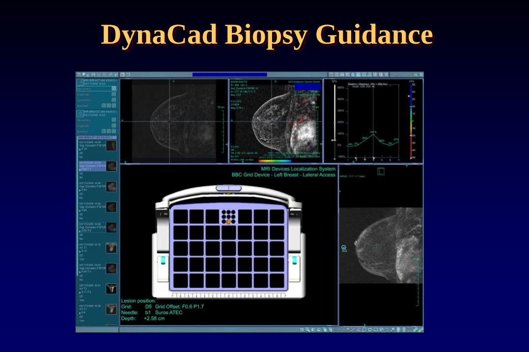
DynaCad Biopsy Guidance

MR-guided Breast Biopsy
(1)Dynamic MRI to locate target
(2)Axial Post to verify skin-target distance
(3)Fast, high BW sequence to localize
(4)Post-Bx images to verify

Breast MRI Quality Control
Quality control of MRI systems used for diagnostic breast
MR imaging and biopsy guidance
• Is important to ensure production of high quality images
by evaluating whether MRI scanner and coils used for
breast imaging are performing consistently over time.
• Should be part of a comprehensive MRI quality control
program.
• May be required to satisfy accreditation program
requirements

www.acr.org
ACR Breast MRI Accreditation Program

• Any field strength
• Coils capable of simultaneous bilateral imaging
• Must accredit all MR systems at the facility that are
used to perform diagnostic breast MR imaging. Does
not include:
• Dedicated systems used for radiation therapy
treatment planning
• Dedicated interventional MRI systems
• Systems used for MR-guided breast biopsy but not
breast MR imaging
ACR Breast MRI Accreditation Program

ACR Breast MRI Accreditation Program
• Currently no phantom image submission.
• Clinical case (bilateral) for each scanner
• BI-RADS category 6: known, enhancing, biopsy-proven
malignancy
• Quality control program and medical physicist involvement
essentially the same as MRI Accreditation Program (MRAP)
• Breast MRI-specific experience/training requirements for
technologists and radiologists.
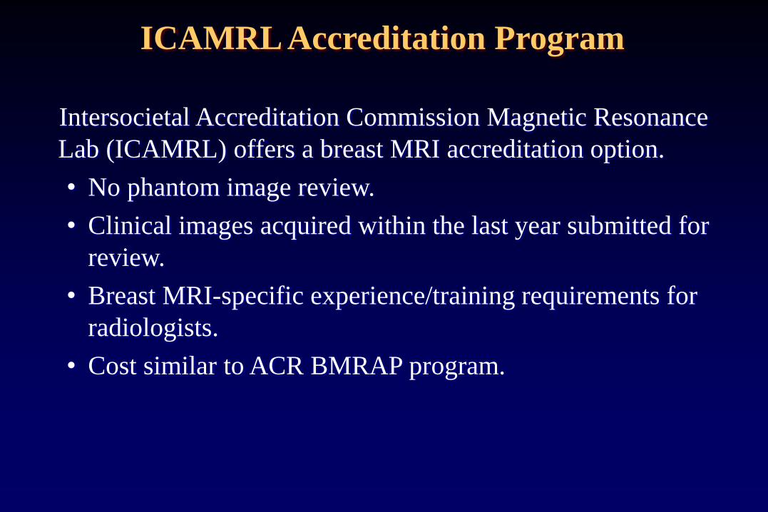
Intersocietal Accreditation Commission Magnetic Resonance
Lab (ICAMRL) offers a breast MRI accreditation option.
• No phantom image review.
• Clinical images acquired within the last year submitted for
review.
• Breast MRI-specific experience/training requirements for
radiologists.
• Cost similar to ACR BMRAP program.
ICAMRL Accreditation Program

• Quality control program established by Quality Assurance
Committee and/or the Medical Director. Tests performed according
to manufacturer’s performance standards.
• Acceptance testing required after installation and major upgrades.
• Periodic maintenance (PM) required
• QC performed by MR technologist, service engineer, medical
physicist or “qualified expert”.
• Daily and periodic QC required
• Equipment function and safety
• Center frequency
• SNR
• Uniformity
• Artifact assessment
ICAMRL Accreditation Program

Breast MRI QC Physicist:
• MRI system performance evaluation after scanner
installation, annually and following major repair or
hardware/software upgrade
• Annual QC of all RF coils (including breast MRI coils)
• Review of technologist QC
Service engineer:
• Periodic/preventative maintenance (PM). Frequency
defined in service contract
MRI technologist:
• Daily/weekly phantom scans
• Image quality assessment during acquisition

Breast MRI QC
Radiologist:
• Review of clinical images for quality, diagnostic value
• Provide feedback to technologist
• Positioning
• Quality of fat saturation
• Use of appropriate sequences/scan parameters
• Optimization of breast MR protocols
• Incorporation of new sequences, coils,
or scan options
In collaboration with
the MR Physicist for
technical guidance

QC program identical to ACR MRAP.
• Acceptance, annual, post-upgrade/repair testing
• Annual testing of all RF coils
Daily/weekly QC:
Choice of phantom and action criteria determined by
“qualified medical physicist/MR scientist in
cooperation with the system vendor”.
• Large ACR phantom in head coil
• Dedicated breast MR systems may choose to use small
ACR phantom in breast coil.
• Other vendor-supplied phantom
ACR BMRAP Quality Control Program

Quality Control - Technologist
Technologist QC test Minimum frequency*
Center frequency Weekly
Table positioning Weekly
Set up & scanning Weekly
Geometric accuracy Weekly
High contrast resolution Weekly
Low contrast resolution Weekly
Artifact analysis Weekly
Film QC Weekly
Visual Checklist Weekly
*daily recommended

Breast MRI Quality Control
The small ACR phantom may
be utilized for breast MR
system QC. Phantom contains
objects that allow evaluation
of:
• geometric accuracy
• high contrast spatial resolution
• slice thickness accuracy
• slice position accuracy
• image intensity uniformity
• ghosting
• low contrast detectability, SNR
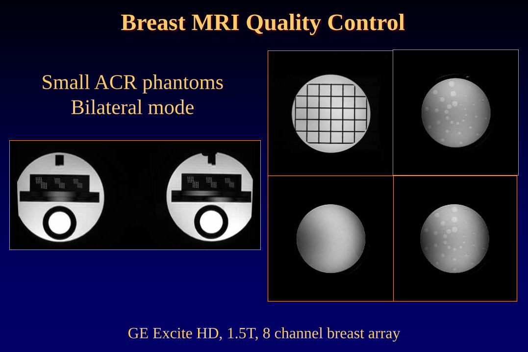
GE Excite HD, 1.5T, 8 channel breast array
Small ACR phantoms
Bilateral mode
Breast MRI Quality Control

Must include:
• MRI Equipment Evaluation
Summary form
• Include all data pages (entire report),
not just summary page
• Indicate corrective action taken
• Evaluation of the Technologist
QC program form.
(physicist must repeat Tech QC)
Annual System Performance Evaluation
report
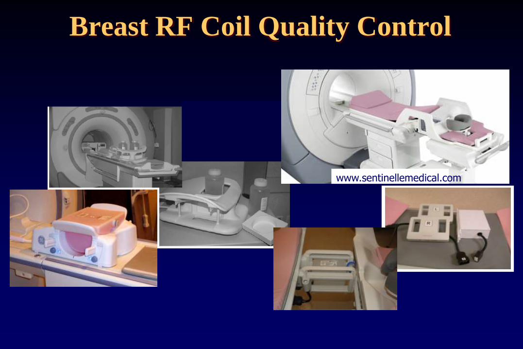
Breast RF Coil Quality Control
www.sentinellemedical.com

Breast RF Coil Quality Control
Establish baseline coil performance in order to monitor coil
performance over time.
• Coil inspection
• Signal-to-noise ratio (SNR)
• Signal uniformity
• Phased array coils: compare SNR for individual channels
• Artifact evaluation (including ghosting)
• Using QC protocol
• Using clinical protocol

Coil testing:
• Important to test coils:
• after installation of new scanner or new coils
• at least annually
• whenever artifacts or coil problems occur
• Manufacturers provide a coil manual for each coil
• includes description of clinical use of the coil
• may include detailed description of coil test procedure
• may include pass/fail limits
• may only say “establish baseline and monitor over time”
Breast RF Coil Quality Control
Consistent scan/measurement methods:
Identical phantom and positioning within coil
• Homogeneous phantom (sphere, cylinder, custom)
• ACR or other phantom
Identical scan parameters:
• Pulse sequence, timing parameters, slice thickness and position, matrix, FOV, receive bandwidth, etc
• Record center frequency, transmit gain/attenuation, receiver gains
Identical measurement methods, ROI positions
• SNR, signal uniformity, ghosting, stability tests
• Evaluation of channel performance
Breast RF Coil Quality Control

Coil inspection
• Inspect coil, cables, cable insulation, ports and
connectors for damage
• Could present a safety issue or result in low SNR or
image artifacts.
www.invivocorp.com
Breast RF Coil Quality Control

Measuring coil SNR
Method 1:
SNR = mean signal within ROI divided by the noise (std dev
of the same ROI or in background)
This method can be used for surface coils:
Maximum signal ROI / noise std dev

Method 2:
SNR = 0.655 x mean Signal divided by the std deviation (of
an ROI in air)
0.655 factor corrects for the background signal in magnitude
images having Rician distribution,
rather than Gaussian
Noise ROI should be placed to avoid
artifacts
Measuring coil SNR

Method 3: (NEMA subtraction)
Acquire 2 images with exactly same parameters
Subtract one image from the other
SNR = √2 x mean signal of ROI in one image / std dev of
ROI in subtracted images.
Measuring coil SNR

Method 4:
Acquire signal image
Turn off RF excitation (service mode) – acquire noise image
Noise value is the standard deviation of ROI in noise image
Measuring coil SNR
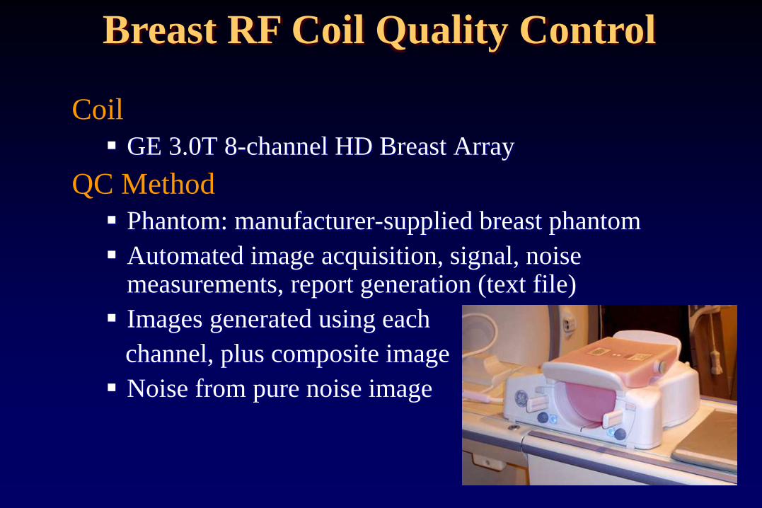
Coil
GE 3.0T 8-channel HD Breast Array
QC Method
Phantom: manufacturer-supplied breast phantom
Automated image acquisition, signal, noise measurements, report generation (text file)
Images generated using each
channel, plus composite image
Noise from pure noise image
Breast RF Coil Quality Control

Coronal image Sagittal composite image Noise image
Images acquired with individual coil elements
Breast RF Coil Quality Control

Coil
Invivo 1.5T 7-channel Breast Array
QC Method
Described in coil manual
Phantom: manufacturer-supplied phantoms (bottle phantoms)
Manual image acquisition, user-drawn ROIs to measure signal, noise
Manufacturer SNR protocol: noise measured in air
Breast RF Coil Quality Control
http://www.invivocorp.com/coils

Breast RF Coil Quality Control
Unilateral biopsy mode Bilateral imaging mode

Summary
• High quality breast MR images exhibit adequate SNR and contrast, high resolution, absence of artifacts, and uniform fat/silicone saturation. Compromises are often necessary to achieve this in addition to good temporal resolution of the DCE series.
• Effective and uniform fat saturation can be challenging to achieve and can be more consistent with technologist education and use of proper shim techniques.
• A comprehensive quality control program, including testing of breast RF coils, is important to ensure optimal performance and image quality of breast MRI systems.