breathing circuits-general principles and components by-dr suchit khanduja
TRANSCRIPT

BREATHING CIRCUITS-GENERAL PRINCIPLES AND COMPONENTS
BY-DR SUCHIT KHANDUJA

Is a gas pathway connected to the patient, through which gas flows occur at respiratory pressures, and into which a controlled composition of a gas mixture is dispensed .
The breathing system is usually regarded as extending from the point of fresh gas inlet to the point at which gas escapes to atmosphere or a scavenging system.
Scavenging equipment is not considered part of the breathing system.
The breathing system receives the gas mixture from the anesthesia machine, delivers gas to the patient, re-moves carbon dioxide, and the conditions temperature and humidity of the inspired mixture
It allows the continuous flow from the anesthesia machine to be converted into an intermittent flow; allows spontaneous, controlled, or assisted respiration; and provides for other functions such as gas sampling and airway pressure, flow, and volume monitoring
INTRODUCTION

When gas passes through a tube, the pressure at the outlet will be lower than that at the inlet
The drop in pressure is a measure of the resistance that must be overcome as the gas moves through the tube.
Resistance varies with the volume of gas passing through per unit of time. Therefore, flow rate must be stated when a specific resistance is mentioned.
The nature of the flow is important in determining resistance. There are two types of flow: laminar and turbulent. In clinical practice, flow is usually a mixture of both
General PrinciplesResistancePhysics
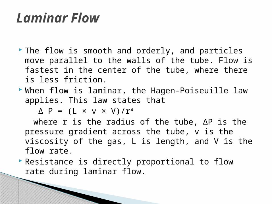
The flow is smooth and orderly, and particles move parallel to the walls of the tube. Flow is fastest in the center of the tube, where there is less friction.
When flow is laminar, the Hagen-Poiseuille law applies. This law states that
Δ P = (L × v × V)/r4
where r is the radius of the tube, ΔP is the pressure gradient across the tube, v is the viscosity of the gas, L is length, and V is the flow rate.
Resistance is directly proportional to flow rate during laminar flow.
Laminar Flow
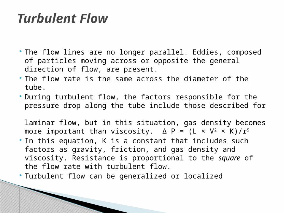
The flow lines are no longer parallel. Eddies, composed of particles moving across or opposite the general direction of flow, are present.
The flow rate is the same across the diameter of the tube.
During turbulent flow, the factors responsible for the pressure drop along the tube include those described for laminar flow, but in this situation, gas density becomes more important than viscosity. Δ P = (L × V2 × K)/r5
In this equation, K is a constant that includes such factors as gravity, friction, and gas density and viscosity. Resistance is proportional to the square of the flow rate with turbulent flow.
Turbulent flow can be generalized or localized
Turbulent Flow

Generalized Turbulent Flow When the flow of gas through a tube exceeds a
certain value, called the critical flow rate, generalized turbulent flow results.
Localized Turbulent Flow When gas flow is below the critical flow rate but
encounters constrictions, curves, valves, or other irregularities, an area of localized turbulence results.
The increase in resistance will depend on the type and number of obstructions encountered.
To minimize resistance, gas-conducting pathways should have minimal length and maximal internal diameter and be without sharp curves or sudden changes in diameter.

Significance of Resistance Resistance imposes a strain, especially with ventilatory modes
where the patient must do part or all of the respiratory work (e.g., spontaneous respiration, intermittent mandatory ventilation, or pressure support ventilation).
Changes in resistance tend to parallel changes in the work of breathing. The tracheal tube is usually the source of more resistance and a more important factor when determining the work of breathing than the breathing system .
There is lack of agreement about what level of resistance is excessive.
Anesthesia providers should be aware of how much resistance components of breathing systems offer and to employ, wherever possible, those offering the least resistance.
For some patients, increased expiratory resistance may be desirable. This should be achieved by using devices designed for that purpose.
Flow-volume loops can show changes in resistance to flow in a breathing system.
Compliance Compliance is the ratio of a change in
volume to a change in pressure. It is a measure of distensibility and is
usually expressed in milliliters per centimeter of water (mL/cm H2O).
The most distensible breathing system components are the reservoir bag and the breathing tubes.
Compliance will help to determine the tidal volume
Compliance can be illustrated graphically with a pressure-volume

Rebreathing Rebreathing means to inhale previously
respired gases from which carbon dioxide may or may not have been removed.
There is a tendency to associate the word rebreathing with carbon dioxide accumulation.
Although rebreathing can result in higher inspired carbon dioxide concentrations than normal, it is possible to have partial or total rebreathing without an increase in carbon dioxide.

Factors Influencing Rebreathing Fresh Gas Flow The amount of rebreathing varies inversely
with the total fresh gas flow. If the volume of fresh gas supplied per minute
is equal to or greater than the patient's minute volume, there will be no rebreathing, as long as provision is made for unimpeded exhaust to atmosphere or to a scavenging system at a point close to the patient's respiratory tract.
If the total volume of gas supplied per minute is less than the minute volume, some exhaled gases must be rebreathed to make up the required volume (assuming no air dilution).

Mechanical (Apparatus) Dead Space Mechanical dead space is the volume in a
breathing system occupied by gases that are rebreathed without any change in composition.
Apparatus dead space can be minimized by separating the inspiratory and expiratory gas streams as close to the patient as possible.
If there is a leak around a face mask, dead space decreases .
The mechanical dead space should be distinguished from the physiological dead space, which includes (a) anatomical dead space, consisting of the patient's conducting airway down to the alveoli, and (b) alveolar dead space, which is the volume of alveoli ventilated but not perfused.

The gas composition in the mechanical dead space will vary according to whether it is occupied by anatomical dead space gas, alveolar gas, or mixed exhaled gas.
Gas exhaled from the anatomical dead space has a composition similar to inspired gas but is saturated with water vapor and is warmer.
Alveolar gas is saturated with water vapor at body temperature and has less oxygen and more carbon dioxide than inspired gas.
The concentration of anesthetic agent in alveolar gas will differ from that in the inspired gas.
Mixed expired gas will have a composition intermediate between that of anatomical dead space and alveolar gas.

Breathing System Design In addition to the above factors, the various
components of a breathing system may be arranged so that there is more or less rebreathing.
Effects of Rebreathing With no rebreathing, the composition of
inspired gas is identical to that of the fresh gas delivered by the anesthesia machine.
With rebreathing, the inspired gas is composed partly of fresh gas and partly of rebreathed gas.

Heat and Moisture Retention Fresh gas from the anesthesia machine is
dry and at room temperature. Exhaled gases are warm and saturated with
moisture. Rebreathing reduces heat and moisture loss
from the patient. In most breathing systems, heat is rapidly
lost to atmosphere, and gas that is reinhaled has a lower temperature and moisture content than exhaled gas.

Altered Inspired Gas Tensions The effects of rebreathing on inspired gas
tensions will depend on what parts of the exhaled gases are rebreathed and whether these pass to the alveoli (and so influence gas exchange) or only to the anatomical dead space.
Oxygen Rebreathing alveolar gas will cause a
reduction in the inspired oxygen tension.
Inhaled Anesthetic Agents Rebreathing alveolar gas exerts a
“cushioning” effect on changes in inspired gas composition with alterations in fresh gas composition.
During induction, when alveolar tensions are lower than those in the fresh gas flow, rebreathed alveolar gas will reduce the inspired tension and prolong induction.
During recovery, the alveolar tension exceeds that of the inspired gases, and rebreathing slows agent elimination.
Carbon Dioxide Rebreathing alveolar gas will cause an increased
inspired carbon dioxide tension unless the gas passes through an absorbent before being rebreathed.
Because carbon dioxide is concentrated in the alveolar portion of expired gases, the efficiency with which it is eliminated from a breathing system varies.
If the system is designed so that alveolar gas is preferentially eliminated through the adjustable pressure limiting (APL) valve or the ventilator spill valve, carbon dioxide retention will be minimal, even with a low fresh gas flow.
Systems that do not maintain the separation between fresh gas, dead space gas, and alveolar gas require relatively high fresh gas flows to eliminate carbon dioxide.
With spontaneous respiration, carbon dioxide retention is generally considered undesirable.
Although the patient can compensate by increasing minute volume, a price is paid in terms of increased work of breathing.
In some cases, compensation by increasing minute volume may not be adequate.
During controlled ventilation, some carbon dioxide in the inhaled gases may be advantageous.
Rebreathing will allow normocarbia to be achieved despite hyperventilation.
Hypocarbia can be avoided and heat and moisture retained.

Discrepancy between Inspired and Delivered Volumes
The volume of gas discharged by a ventilator or reservoir bag usually differs from that which enters the patient.
The volume actually inspired may be less or greater than that delivered.

Causes of Increased Inspired Volume When a ventilator is in use and the fresh gas
flow rate is greater than the rate at which it is absorbed by the patient or lost through leaks in the breathing system, the fresh gas flow delivered during inspiration may be added to the tidal volume delivered by the ventilator .
This augmentation increases with higher fresh gas flows and I:E ratios and lower respiratory rates .
Modern anesthesia ventilators have been designed to eliminate the additional tidal volume caused by fresh gas flow.
Causes of Decreased Inspired Volume A reduction in the tidal volume delivered to
the patient will result from gas compression and distention of breathing system components during inspiration .
This is referred to as wasted ventilation. Wasted ventilation increases with increases
in airway pressure, tidal volume, increased breathing system volume, and component distensibility .
Proportionally, more of the set tidal volume is lost with small patients.
Tidal volume is also decreased by leaks in the breathing system. The amount lost will depend on the size and location of the leaks and the pressure in the breathing system.
Tidal volumes are best measured between the patient and the breathing tubes .
Measuring tidal volume at the end of the expiratory limb will reflect increases caused by fresh gas flow and decreases resulting from leaks in the breathing system but will miss decreases from wasted ventilation.
Leaks between the volume sensor located at the patient port and the patient can be detected by comparing the inspired and exhaled tidal volumes.
If there is a significant leak, the exhaled volume will be less than the inspired volume.

Discrepancy between Inspired and Delivered Volumes
The volume of gas discharged by a ventilator or reservoir bag usually differs from that which enters the patient.
The volume actually inspired may be less or greater than that delivered.
Causes of Increased Inspired Volume When a ventilator is in use and the fresh gas flow rate is
greater than the rate at which it is absorbed by the patient or lost through leaks in the breathing system, the fresh gas flow delivered during inspiration may be added to the tidal volume delivered by the ventilator .
This augmentation increases with higher fresh gas flows and I:E ratios and lower respiratory rates.
Modern anesthesia ventilators have been designed to eliminate the additional tidal volume caused by fresh gas flow. For an in-depth discussion of this subject and how modern ventilators deal with it.
Causes of Decreased Inspired Volume A reduction in the tidal volume delivered to the patient will result from
gas compression and distention of breathing system components during inspiration .
This is referred to as wasted ventilation. Wasted ventilation increases with increases in airway pressure, tidal volume, increased breathing system volume, and component distensibility .
Proportionally, more of the set tidal volume is lost with small patients . Tidal volume is also decreased by leaks in the breathing system. The
amount lost will depend on the size and location of the leaks and the pressure in the breathing system.
Tidal volumes are best measured between the patient and the breathing tubes .
Measuring tidal volume at the end of the expiratory limb will reflect increases caused by fresh gas flow and decreases resulting from leaks in the breathing system but will miss decreases from wasted ventilation.
Leaks between the volume sensor located at the patient port and the patient can be detected by comparing the inspired and exhaled tidal volumes. If there is a significant leak, the exhaled volume will be less than the inspired volume.

Discrepancy between Inspired and Delivered Oxygen and Anesthetic Gas Concentrations
The composition of the gas mixture that exits the machine may be modified by the breathing system so that the mixture the patient inspires differs considerably from that delivered to the system. There are several contributing factors.
Rebreathing The effect of rebreathing will depend on the
volume of the rebreathed gas and its composition.

Air Dilution If the fresh gas supplied per respiration is less than the
tidal volume, negative pressure in the breathing system may cause air dilution if there is a leak.
Air dilution makes it difficult to maintain a stable anesthetic state.
It causes the concentration of anesthetic in the inspired mixture to fall.
This results in a lighter level of anesthesia with stimulated ventilation.
The increased ventilation causes more air dilution. The opposite is also true.
Deepening anesthesia depresses ventilation. Respiratory depression decreases air dilution, which
causes an increase in the inspired anesthetic agent concentration. This in turn leads to further depressed respiration.

Leaks When a leak occurs, positive pressure in the
system will force gas out of the system. The composition and amount of the gas lost
will depend on the location and size of the leak, the pressure in the system, and the compliance and resistance of both the system and the patient.

Anesthetic Agent Uptake by the Breathing System Components
Anesthetic agents may be taken up or adhere to rubber, plastics, metal, and carbon dioxide absorbent .
This will lower the inspired concentration. Uptake will be directly proportional to the
concentration gradient between the gas and the components, the partition coefficient, the surface area, the diffusion coefficient, and the square root of time.

Anesthetic Agents Released from the System
Elimination of anesthetic agent from the breathing system will depend on the same factors as uptake.
The system may function as a low output vaporizer for many hours after a vaporizer has been turned OFF even if the rubber goods and absorbent are changed.
This can result in a patient being inadvertently exposed to the agent.
Bushings (Mounts) A bushing serves to modify the internal
diameter of a component. Most often, it has a cylindrical form and is
inserted into, and becomes part of, a pliable component such as a reservoir bag or a breathing tube.
Sleeves A sleeve alters the external diameter of a
component.
Components
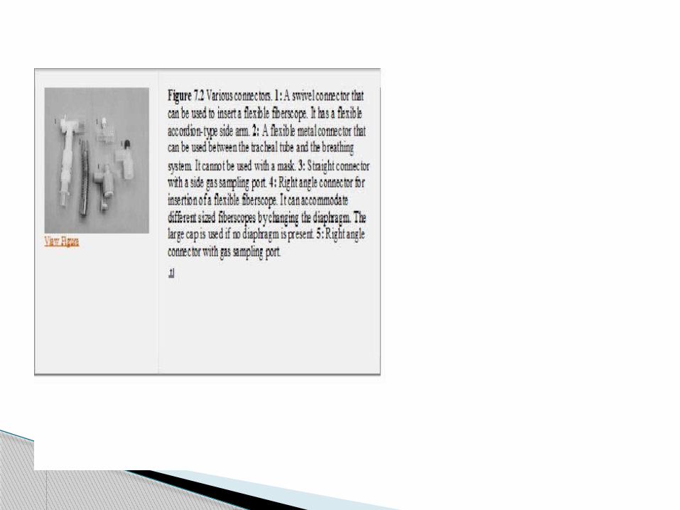
Connectors and Adaptors A connector is a fitting intended to join
together two or more similar components. An adaptor is a specialized connector that
establishes functional continuity between otherwise disparate or incompatible components.
An adaptor or connector may be distinguished by (a) shape (e.g., straight, right angle or elbow, T, or Y), (b) component(s) to which it is attached, (c) added features (e.g., with nipple or APL valve), and (d) size and type of fitting at either end (e.g., 15-mm male, 22-mm female).
All anesthesia breathing systems terminate at the patient connection port.
This is the point where the breathing system connects to a device that establishes continuity with the patient's respiratory system (a tracheal tube, face mask, or supraglottic airway device).
All face masks have a 22-mm female opening while most other devices have a 15-mm male fitting.
To facilitate the change from mask to tracheal tube, and the like, a component having a 22-mm male fitting with a concentric 15-mm female fitting is used at the patient connection port.
Usually, this component is a right angle connector , also known as an elbow adaptor, elbow joint, elbow connector, mask angle piece, mask adaptor, or mask elbow.
Connectors and adaptors can be used to: Extend the distance between the patient
and the breathing system. This is especially important in head and
neck surgery. Change the angle of connection between
the patient and the breathing system. Allow a more flexible and/or less kinkable
connection between the patient and the breathing system.
Increase the dead space.

Resistance increases with sharp curves and rough sidewalls.
Connectors add dead space if positioned between the breathing system and the patient. In the adult patient, this may not be of much significance. However, in infants, any increase in dead space may be excessive.
Connectors increases the number of locations at which disconnections can occur.
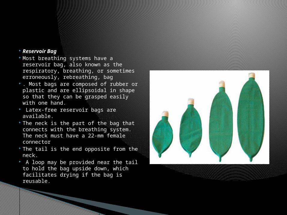
Reservoir Bag Most breathing systems have a
reservoir bag, also known as the respiratory, breathing, or sometimes erroneously, rebreathing, bag
. Most bags are composed of rubber or plastic and are ellipsoidal in shape so that they can be grasped easily with one hand.
Latex-free reservoir bags are available.
The neck is the part of the bag that connects with the breathing system. The neck must have a 22-mm female connector
The tail is the end opposite from the neck.
A loop may be provided near the tail to hold the bag upside down, which facilitates drying if the bag is reusable.

The bag has the following functions: It allows gas to accumulate during exhalation. This
provides a reservoir of gas for the next inspiration. This permits rebreathing, allows more economical
use of gases, and prevents air dilution. It provides a means whereby ventilation may be
assisted or controlled. It can serve through visual and tactile observation
as a monitor of a patient's spontaneous respiration.
Because the bag is the most distensible part of the breathing system, it protects the patient from excessive pressure in the breathing system.
The pressure-volume characteristics of bags become important if there is no way for gases to escape from the system and inflow continues.
Adding volume to a bag normally causes a negligible rise in pressure until the nominal capacity is reached.
As more volume continues to be added, the pressure rises rapidly to a peak and then reaches a plateau. As the bag distends further, the pressure falls slightly. The peak pressure is of particular interest, because this represents the maximal pressure that can develop in a breathing system.
The American Society for Testing and Materials (ASTM) standard for reservoir bags requires that for bags of 1.5 L or smaller, the pressure shall be not less than 30 cm H2O or over 50 cm H2O when the bag is expanded to four times its capacity .
For bags larger than 1.5 L, the pressure shall be not less than 35 cm H2O or over 60 cm H2O when the bag is expanded to four times its size.
Latex-free reservoir bags may allow higher pressures to develop .
New bags develop greater pressures when first overinflated than do bags that have been overinflated several times or have been prestretched .
It is good practice to overinflate or stretch a new bag during the preuse checkout.
This will not limit the ability to produce high airway pressures when the bag is squeezed.

Bags are available in a variety of sizes. The size that should be used will depend on the
patient, the breathing system, and the user's preference.
A 3-L bag is traditional for use in adults. A larger bag may be difficult to squeeze and will
make monitoring the patient's spontaneous respiration more difficult because the excursions will be smaller.
A small bag, on the other hand, provides less safety with respect to pressure fluctuations and may not provide a large enough reservoir or tidal volume.
A spare bag should always be kept immediately available in case the bag develops a leak or becomes lost.

Breathing Tubes A large-bore, corrugated
plastic breathing (conducting) tube (hose) provides a flexible, low-resistance, lightweight connection from one part of the system to another.
Corrugations increase flexibility and help to prevent kinking.
Breathing tubes have some distensibility but not enough to prevent excessive pressures from developing.
Smaller diameter breathing tubings are available for circle systems used for pediatric patients

If it is necessary to have the anesthesia machine at some distance from the patient's head, several breathing tubes may be connected in series or extra-long tubings can be used. Special tubings that can be elongated are available .
A tube holder (tree) can be used to support breathing tubes and prevent them from exerting a pull on the airway device.

Adjustable Pressure-Limiting Valve The APL valve is a user-adjustable valve
that releases gases to a scavenging system. It is used to control the pressure in the breathing system.

Construction Control Part The control part serves to control the pressure at which
the valve opens. Most of these valves are calibrated for the opening pressure . Several types are available.
Spring-loaded Disc The most commonly used APL valve uses a disc held
onto a seat by a spring . A threaded screw cap over the spring allows the
pressure exerted by the spring on the disc to be varied. When the cap is fully tightened, the disc will prevent
any gas from escaping from the system. As the cap is loosened, the tension on the spring is reduced so that the disc can rise.

When the pressure in the breathing system increases, it exerts an upward force on the disc. When this upward force exceeds the downward force exerted by the spring, the disc rises and gas flows through the valve.
When the pressure in the system falls, the disc returns to its seat.
When the cap is at its maximum open position, there will be only minimal pressure exerted by the spring.
This allows the patient's exhalation to lift the disc with only minimal pressure.
The weight of and pressure on the disc ensures that the reservoir bag fills before the disc rises.
Increased pressure downstream of the APL valve will increase the pressure needed to open the valve.
Positive end-expiratory pressure (PEEP) may then be transmitted to the patient.

Stem and Seat Another control part employed in APL valves is the
stem and seat . This is similar to a flow control valve in that a
threaded stem allows variable contact with a seat. As the valve is opened, the opening at the seat
becomes larger and more gas is allowed to escape.
Some of these valves have a disc or ball valve in a retaining cage .
This served the dual function of preventing gas from the scavenging system from flowing back into the breathing system and supplying a slight pressure to keep the reservoir bag inflated.
Sticking of this part has been reported .
Control Knob Most APL valves have a rotary control knob. The ASTM standard requires that valves with
rotating controls be designed so that a clockwise motion increases the limiting pressure and ultimately closes the valve .
It also requires an arrow or other marking to indicate the direction of movement required to close the valve .
The standard recommends that the full range of relief pressure be adjusted by less than one full turn of the control.
Some of these valves are marked to show the pressure at which they will open .


Collection Device and Exhaust Port In order to remove excess gases from the
breathing system and direct them to a scavenging system, they must be collected by using a collection device at the APL valve.
The gases are then directed to the scavenging system through the transfer tubing
. The exhaust port is the aperture through which excess gases are discharged to the scavenging system.
It must have a 19- or 30-mm male connector .
Use Spontaneous Respiration With spontaneous respiration, the APL valve
remains closed during inspiration and opens during exhalation.
Normally, the valve is fully open during spontaneous ventilation.
It should be closed slightly only if gas is withdrawn from the breathing system by negative pressure from the scavenging system and the reservoir bag collapses.
Partially closing the valve during spontaneous respiration will result in continuous positive airway pressure (CPAP).

With spontaneous respiration, the anesthesia provider must be constantly aware of volume of gas in the bag.
If attention is diverted, the bag may collapse or become overdistended.
Negative pressure transmitted from the scavenging system may cause gases to be evacuated from the breathing system.
An obstruction in the scavenging system may result in the bag becoming overdistended and the patient being subjected to CPAP.

During manually controlled or assisted ventilation, the valve is usually left partially open.
During inspiration, the bag is squeezed and pressure increases until the relief pressure is reached.
Before this, the patient receives all of the gas displaced from the bag (less a small amount due to gas compression and expansion of the tubes).
Once the APL valve opens, the additional volume that the patient receives is determined by the relative resistances to flow exerted by the patient and the APL valve.
Manually Controlled or Assisted Ventilation

The APL valve must be adjusted on the basis of chest movements and/or exhaled volume or pressure measurements to achieve the desired level of ventilation and to maintain adequate bag volume.
The resistance felt during bag compression (“the educated hand”) cannot be relied on to ensure adequate ventilation .
If compliance falls or resistance increases, the valve must be tightened.
If the fresh gas flow is increased or decreased, the APL valve must be opened or closed somewhat.
Some APL valves have a lever for changing between spontaneous and manual ventilation.

Mechanical Ventilation Bag-ventilator selector switches (selector
valves) that facilitate the change from manual to automatic ventilation are available .
These isolate the APL valve when the selector valve is turned to automatic ventilation.
When isolated from the breathing system, the APL valve need not be closed during mechanical ventilation
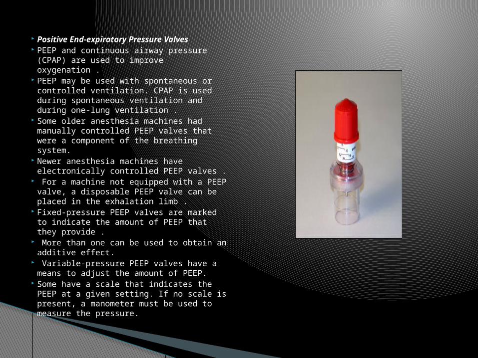
Positive End-expiratory Pressure Valves
PEEP and continuous airway pressure (CPAP) are used to improve oxygenation .
PEEP may be used with spontaneous or controlled ventilation. CPAP is used during spontaneous ventilation and during one-lung ventilation .
Some older anesthesia machines had manually controlled PEEP valves that were a component of the breathing system.
Newer anesthesia machines have electronically controlled PEEP valves .
For a machine not equipped with a PEEP valve, a disposable PEEP valve can be placed in the exhalation limb .
Fixed-pressure PEEP valves are marked to indicate the amount of PEEP that they provide .
More than one can be used to obtain an additive effect.
Variable-pressure PEEP valves have a means to adjust the amount of PEEP.
Some have a scale that indicates the PEEP at a given setting. If no scale is present, a manometer must be used to measure the pressure.

Using PEEP in a spontaneously breathing patient will result in increased work of breathing .
Using PEEP with certain ventilatory modes may result in a substantial decrease in the tidal volume delivered to the patient.
The breathing system may become occluded and barotrauma may result if a PEEP valve malfunctions.
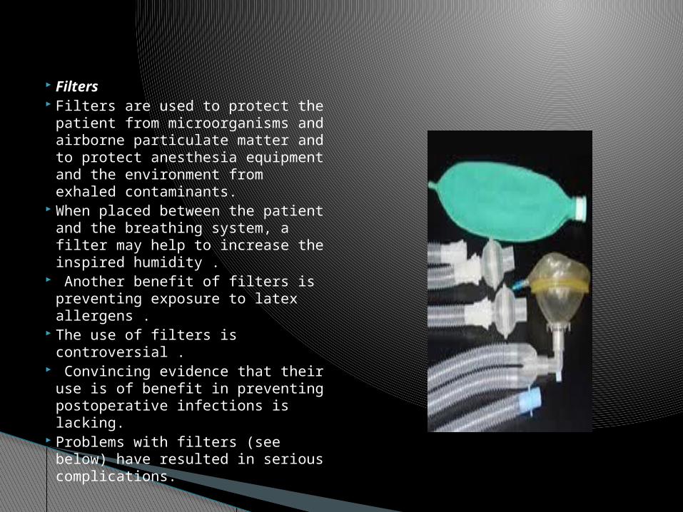
Filters Filters are used to protect the
patient from microorganisms and airborne particulate matter and to protect anesthesia equipment and the environment from exhaled contaminants.
When placed between the patient and the breathing system, a filter may help to increase the inspired humidity .
Another benefit of filters is preventing exposure to latex allergens .
The use of filters is controversial .
Convincing evidence that their use is of benefit in preventing postoperative infections is lacking.
Problems with filters (see below) have resulted in serious complications.

The Centers for Disease Control and Prevention (CDC) and the American Society of Anesthesiologists (ASA) make no recommendation for placing a filter in the breathing system unless there is suspicion that the patient has an infectious pulmonary disease .
The Association of Anaesthetists of Great Britain and Ireland (AAGBI) and others recommend that either a filter be placed between the patient and the breathing system with a new filter being used for each adult patient or that a new breathing system be used for each patient .
Studies show that filters do become contaminated on the machine side.
For pediatric patients, the increased resistance and relative inefficiency of pediatric filters may make other means of humidification and infection control more attractive .
The AAGBI recommends that filters not be used for pediatric patients; rather, the breathing system should be replaced between cases.

Filter efficiency varies . A high-efficiency particulate aerosol (HEPA)-grade
device is defined as one capable of trapping at least 99.97% of particles having a diameter of 0.3 µm .
Filter efficiency depends on the experimental test conditions.
Therefore, when filter efficiency is stated, the size of the challenge particle or organism should be disclosed.
The approximate size of the human immunodeficiency virus (HIV) particle is 0.08 µ; hepatitis C virus, 0.06 µm; mycobacterium tuberculosis, 0.3 µm; pseudomonas aeruginosa, 0.5 µ; and staphlococcus aureus, 1.0 µ.

Problems Associated with Filters Increased Resistance and Dead Space A filter increases the resistance to gas flow. Resistance
will increase as condensation accumulates . While increased resistance is usually not a problem
during controlled ventilation, it may be problematic with spontaneous respiration.
Adding a filter between the patient and the breathing system increases the dead space.
Unless ventilation is increased, significant rebreathing can occur .
Spontaneously breathing patients who derive a major portion of their minute volume from shallow breaths may find the increase in dead space excessive .
A large filter should not be used in this location with pediatric patients. Pediatric filters are available.

Obstruction Filters may be obstructed by exhaled
blood, edema or regurgitated fluid, a manufacturing defect, sterilization of a disposable filter, nebulized drugs, or inserting a unidirectional filter backward .
A filter should not be used with a patient who produces copious secretions or downstream of a humidifier or nebulizer.
An increase in peak inspiratory pressure may indicate the need to replace a filter.
Leaks A defect in a filter can cause a leak .

Filter Location in the Breathing System Filters used in anesthesia breathing systems are
supplied in three forms: (a) attached to a disposable breathing tube (b) attached to a ventilator hose (c) as a separate component. A filter placed at
the patient port may permit disposable breathing systems to be reused. However, the external surface of these systems will not be protected.
A filter should not be placed downstream of a humidifier or nebulizer, because it may become less efficient when wet.
In addition, an increase in resistance, sometimes to a hazardous level, may be seen

Liquid Penetration Since filters located between the breathing
system and the patient are sometimes exposed to liquids, the ability to contain that liquid is important.
Microbes can transit the filter by way of a liquid that passes through a filter.
There is a great variability among filters in regard to the pressure that will cause liquid to penetrate the filter material .
In general, pleated mechanical filters are more resistant to liquid passage than electrostatic filters.
Other Using a filter between the patient and the breathing
system may result in erroneous end-tidal gas concentrations and poor carbon dioxide waveforms
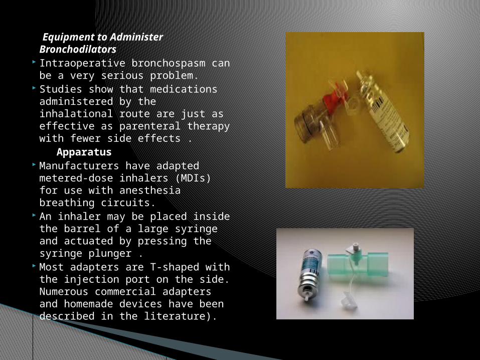
Equipment to Administer Bronchodilators
Intraoperative bronchospasm can be a very serious problem.
Studies show that medications administered by the inhalational route are just as effective as parenteral therapy with fewer side effects .
Apparatus Manufacturers have adapted
metered-dose inhalers (MDIs) for use with anesthesia breathing circuits.
An inhaler may be placed inside the barrel of a large syringe and actuated by pressing the syringe plunger .
Most adapters are T-shaped with the injection port on the side. Numerous commercial adapters and homemade devices have been described in the literature).

The gas sampling port in the breathing system or the sampling lumen of a specialized tracheal tube may be used to deliver medications
Medication may be delivered by a catheter that extends to the tip of the tracheal tube. This method results in more efficient delivery .
The adapter should be placed close to the patient port. There should not be a filter or heat and moisture exchanger (HME) between the adapter and the patient.

A spacer (aerosol holding chamber, reservoir chamber, auxiliary or accessory device, [extension or reservoir]) may be placed downstream or upstream of the MDI to slow the flow of aerosol and to increase impaction and sedimentation of large particles .
Rigid spacers result in more efficient medication delivery than collapsible ones .
Aerosol nebulizers may also be used to deliver bronchodilators to an anesthesia breathing system. The gas used to aerosolize the agent will affect the composition of the inspired gas .
Technique of Use The inhaler should be shaken well prior to administration . Bronchodilator discharge is maximal when the canister is upright. The hole in the adapter should point toward the patient, unless an
upstream spacer is used. Actuating the inhaler just after inspiration begins will maximize
delivery to the airways . If a spacer is used, the MDI should be actuated 1 to 2 seconds
before inspiration or near end-exhalation, depending on the rate .

A slow, deep inspiration, followed by a pause of 2 to 3 seconds before exhalation, will enhance the amount of medication deposited into the airway .
There should be 30 to 60 seconds between puffs. The inhaler must be shaken prior to each puff.
Low humidification is desirable when delivering medication
High humidification causes the aerosol droplets to increase in size, which causes them to rain out.
If possible, humidification should be discontinued when an MDI is used.
Using a spacer will increase bronchodilator delivery and reduce the number of puffs .
However, even with a spacer, as many as 10 to 15 puffs may be required to reach the desired results
The patient should be monitored for the appearance of beneficial and side effects.
Advantages MDIs are easy to use, take little time to set up,
and occupy little space on the anesthesia cart . They are more efficient at delivering
medications and less costly than nebulizers . Disadvantages A large amount of drug is lost due to rainout in
the breathing system and tracheal tube. Improper technique is one factor .
The smaller the tracheal tube, the more drug is deposited in the tube .
Another problem is that the carrier gas may cause erroneous readings with an anesthetic agent analyzer.
Size and Type of Fittings The Compressed Gas Association (CGA) and the ASTM have
published standards that specify the size and type of fittings for components in the breathing system .
Virtually all breathing system components manufactured in the United States in recent years conform to these standards.
The safety provided by standardizing the diameters of various connectors can be jeopardized by the use of adaptors and adhesive tape.
Any component or accessory used in the breathing system that permits only unidirectional flow or any device whose correct function depends on the direction of gas flow through it must be so labeled and marked with an arrow indicating the proper direction of flow or the words inlet and outlet or both.
Distal and proximal are used to designate the proximity of a component to the patient.
A fitting that is part of a component such as an absorber, Y-piece, or reservoir bag mount, whose purpose is to permit attaching this component to a reservoir bag, breathing tube, or mask, must be male and rigid.
Fittings on the breathing tube, mask, and reservoir bag connectors must be female and nonrigid (resilient).
All connectors in an adult breathing system are 22 mm. The patient port must have a coaxial 15-mm female fitting.
The inspiratory and expiratory ports mounted on the absorber and the reservoir bag connector must have male fittings.
To avoid problems with connections between the breathing and scavenging systems, the exit port for the APL valve must have either a 19- or 30-mm male fitting. A 30-mm fitting is preferred.

THANKS!!