breeder/pullet scale control - chore-time poultry
TRANSCRIPT

Breeder/Pullet Scale ControlInstallation & Operator’s Instruction Manual
MT1918AAugust 2006

CTB Inc. Warranty Breeder/Pullet Scale Control
2 MT1918A
CTB Inc. warrants each new C-Collect® product manufactured by it to be free from defects in material or workmanship for one year from and after the date of initial installation by or for the original purchaser. If such a defect is found by the Manufacturer to exist within the one-year period, the Manufacturer will, at its option, (a) repair or replace such product free of charge, F.O.B. the factory of manufacture, or (b) refund to the original purchaser the original purchase price, in lieu of such repair or replacement. Labor costs associated with the replacement or repair of the product are not covered by the Manufacturer.
Conditions and Limitations1. The product must be installed by and operated in accordance with the instructions published by the
Manufacturer or Warranty will be void.2. Warranty is void if all components of the system are not original equipment supplied by the Manufacturer.3. This product must be purchased from and installed by an authorized distributor or certified representative
thereof or the Warranty will be void.4. Malfunctions or failure resulting from misuse, abuse, negligence, alteration, accident, or lack of proper
maintenance shall not be considered defects under the Warranty.5. This Warranty applies only to systems for the care of poultry and livestock. Other applications in industry
or commerce are not covered by this Warranty.
The Manufacturer shall not be liable for any Consequential or Special Damage which any purchaser may suffer or claim to suffer as a result of any defect in the product. “Consequential” or “Special Damages” as used herein include, but are not limited to, lost or damaged products or goods, costs of transportation, lost sales, lost orders, lost income, increased overhead, labor and incidental costs and operational inefficiencies.
THIS WARRANTY CONSTITUTES THE MANUFACTURER’S ENTIRE AND SOLE WARRANTY AND THIS MANUFACTURER EXPRESSLY DISCLAIMS ANY AND ALL OTHER WARRANTIES, INCLUDING, BUT NOT LIMITED TO, EXPRESS AND IMPLIED WARRANTIES AS TO MERCHANTABILITY, FITNESS FOR PARTICULAR PURPOSES SOLD AND DESCRIPTION OR QUALITY OF THE PRODUCT FURNISHED HEREUNDER.
C-Collect® Distributors are not authorized to modify or extend the terms and conditions of this Warranty in any manner or to offer or grant any other warranties for C-Collect® products in addition to those terms expressly stated above. An officer of CTB, Inc. must authorize any exceptions to this Warranty in writing. The Manufacturer reserves the right to change models and specifications at any time without notice or obligation to improve previous models.
Effective: September 2006
CTB Inc.P.O. Box 2000 • Milford, Indiana 46542-2000 • U.S.A.
Phone (574) 658-4101 • Fax (877) 730-8825Email: [email protected] • Internet: http//www.ctbinc.com
Thank You
The employees of CTB Inc. would like to thank your for your recent C-Collect® purchase. If a problem should arise, your C-Collect® distributor can supply the necessary information to help you.
CTB Inc. Warranty
Contents
Topic Page User
MT1918A * Legend: C = Customer (end user), D = Distributor (sales), I = Installer of equipment 3
CTB Inc. Warranty . . . . . . . . . . . . . . . . . . . . . . . . . . . . . . . . . . . . . . . . . . . . . . . . . . 2
General. . . . . . . . . . . . . . . . . . . . . . . . . . . . . . . . . . . . . . . . . . . . . . . . . . . . . . . . . . . . . 4
Safety Information . . . . . . . . . . . . . . . . . . . . . . . . . . . . . . . . . . . . . . . . . . . . . . . . . . . 4Follow Safety Instructions . . . . . . . . . . . . . . . . . . . . . . . . . . . . . . . . . . . . . . . . . . . . . . . . . . . . . 4Decal Descriptions . . . . . . . . . . . . . . . . . . . . . . . . . . . . . . . . . . . . . . . . . . . . . . . . . . . . . . . . . . . 4DANGER: Electrical Hazard . . . . . . . . . . . . . . . . . . . . . . . . . . . . . . . . . . . . . . . . . . . . . . . . . . 4
Introduction to Control . . . . . . . . . . . . . . . . . . . . . . . . . . . . . . . . . . . . . . . . . . . . . . . 5Viewing Screen . . . . . . . . . . . . . . . . . . . . . . . . . . . . . . . . . . . . . . . . . . . . . . . . . . . . . . . . . . . . . 6Scale LED’s . . . . . . . . . . . . . . . . . . . . . . . . . . . . . . . . . . . . . . . . . . . . . . . . . . . . . . . . . . . . . . . . 6Index Keys . . . . . . . . . . . . . . . . . . . . . . . . . . . . . . . . . . . . . . . . . . . . . . . . . . . . . . . . . . . . . . . . . 6Alarm Key . . . . . . . . . . . . . . . . . . . . . . . . . . . . . . . . . . . . . . . . . . . . . . . . . . . . . . . . . . . . . . . . . 7Scale Keys . . . . . . . . . . . . . . . . . . . . . . . . . . . . . . . . . . . . . . . . . . . . . . . . . . . . . . . . . . . . . . . . . 7Subject Keys . . . . . . . . . . . . . . . . . . . . . . . . . . . . . . . . . . . . . . . . . . . . . . . . . . . . . . . . . . . . . . . 8Navigation Keys. . . . . . . . . . . . . . . . . . . . . . . . . . . . . . . . . . . . . . . . . . . . . . . . . . . . . . . . . . . . . 9
Installation. . . . . . . . . . . . . . . . . . . . . . . . . . . . . . . . . . . . . . . . . . . . . . . . . . . . . . . . . . 10Mounting the Control. . . . . . . . . . . . . . . . . . . . . . . . . . . . . . . . . . . . . . . . . . . . . . . . . . . . . . . . . 11Wiring the Control . . . . . . . . . . . . . . . . . . . . . . . . . . . . . . . . . . . . . . . . . . . . . . . . . . . . . . . . . . . 11
Control Setup . . . . . . . . . . . . . . . . . . . . . . . . . . . . . . . . . . . . . . . . . . . . . . . . . . . . . . . 12Installation Setup . . . . . . . . . . . . . . . . . . . . . . . . . . . . . . . . . . . . . . . . . . . . . . . . . . . . . . . . . . . . 12Control Setup . . . . . . . . . . . . . . . . . . . . . . . . . . . . . . . . . . . . . . . . . . . . . . . . . . . . . . . . . . . . . . . 13Same Sex House (Pullet) Setup . . . . . . . . . . . . . . . . . . . . . . . . . . . . . . . . . . . . . . . . . . . . . . . . . 13Breeder (or Mixed Sex Pullet) Setup . . . . . . . . . . . . . . . . . . . . . . . . . . . . . . . . . . . . . . . . . . . . . 14Weighing a New Flock . . . . . . . . . . . . . . . . . . . . . . . . . . . . . . . . . . . . . . . . . . . . . . . . . . . . . . . 15
Wiring Diagrams . . . . . . . . . . . . . . . . . . . . . . . . . . . . . . . . . . . . . . . . . . . . . . . . . . . . 16Breeder/Pullet Control Wiring . . . . . . . . . . . . . . . . . . . . . . . . . . . . . . . . . . . . . . . . . . . . . . . . . . 16Sample Wiring Installation . . . . . . . . . . . . . . . . . . . . . . . . . . . . . . . . . . . . . . . . . . . . . . . . . . . . 17Wiring . . . . . . . . . . . . . . . . . . . . . . . . . . . . . . . . . . . . . . . . . . . . . . . . . . . . . . . . . . . . . . . . . . . . 18Wiring at the Breeder/Pullet Scale Control . . . . . . . . . . . . . . . . . . . . . . . . . . . . . . . . . . . . . . . . 18Wiring at the Load Cell:. . . . . . . . . . . . . . . . . . . . . . . . . . . . . . . . . . . . . . . . . . . . . . . . . . . . . . . 19Wiring at the SJB: . . . . . . . . . . . . . . . . . . . . . . . . . . . . . . . . . . . . . . . . . . . . . . . . . . . . . . . . . . . 19
PC Connection . . . . . . . . . . . . . . . . . . . . . . . . . . . . . . . . . . . . . . . . . . . . . . . . . . . . . . 2047660 FNET/ALARM & 47661 Telephone Line Surge Suppressor Wiring . . . . . . . . . . . . . . 21
Technical Specifications . . . . . . . . . . . . . . . . . . . . . . . . . . . . . . . . . . . . . . . . . . . . . . . 22

General Breeder/Pullet Scale Control
4 MT1918A
Parts List23
The Breeder/Pullet Bird Scale is specially designed for use in Breeder and Pullet (Rearing) applications. The Control's software sets it apart from the Broiler Bird Scale in the following ways:1. It can support up to eight different scale inputs (8 platforms for Pullet Houses, 4
platforms for Breeder/Dual Sex houses)2. The algorithm is designed to handle little or no daily growth3. The scale platforms can be configured to take to two separate ranges of weights
to accommodate both the males and females in the breeder house. Since each platform tracks two different weight ranges over 4 scale platforms can be used.
Caution, Warning and Danger Decals have been placed on the equipment to warn of potentially dangerous situations. Care should be taken to keep this information intact and easy to read at all times. Replace missing or damaged safety decals immediately.Using the equipment for purposes other than specified in this manual may cause personal injury and/or damage to the equipment.
Follow Safety InstructionsCarefully read all safety messages in this manual and on your equipment safety signs. Follow recommended precautions and safe operating practices.Keep safety signs in good condition. Replace missing or damaged safety signs.
Decal Descriptions
DANGER: Electrical Hazard
Disconnect electrical power before inspecting or servicing equipment unless maintenance instructions specifically state otherwise.Ground all electrical equipment for safety.All electrical wiring must be done by a qualified electrician in accordance with local and national electric codes.Ground all non-current carrying metal parts to guard against electrical shock.With the exception of motor overload protection, electrical disconnects and over current protection are not supplied with the equipment.
General
Safety Information

Breeder/Pullet Scale Control Introduction to Control
MT1918A 5
Here is a diagram to help you get more familiar with the various parts of your Breeder/Pullet Scale Control.
Introduction to Control
Item Description1 Bird Scale Control2 Viewing Screen3 Subject Key Pad4 Navigation Keys5 Scale LED’s6 Index Key7 Alarm Key8 Scale Keys9 Edit Key
Figure 1. Intro to Control
1
25
3
4
4
9
7
6
8
6
Item Description1 Load Cell2 Bird Platform Support3 Bird Weighing Platform
Figure 2. Various Parts
1
2
3

Introduction to Control Breeder/Pullet Scale Control
6 MT1918A
Viewing ScreenThe Viewing Screen (Item 1, Figure 3) contains up to four lines and up to 20 characters per line. What is displayed on the screen is determined by which Subject Button is pressed and which platform the information refers to. A cursor will be present when any of the information is editable.
Scale LED’sThe LEDs indicate when a weight has been accepted. For example, if the second LED lights up, that indicates that a weight has been accepted on either scale platform 2 or 6.
Index KeysThe Index Keys (Item 1, Figure 5) help you to move quickly through a screen with multiple lines of data like the History Screen. The Index keys are also used in the Growth Standard screen (Button 13) to choose different types of growth standards (rearers(pullets), hens, cocks, etc) to be viewed.
Figure 3. Viewing Screen
Item Description1 Viewing Screen
1
Figure 4. Scale LED’s
Item Description1 Scale LED’s
1
Figure 5. Index Keys
Item Description1 Index Keys
1

Breeder/Pullet Scale Control Introduction to Control
MT1918A 7
Alarm KeyIf the Alarm Key (Item 1, Figure 6) is blinking, it is indicating that an alarm condition has occurred. To view the alarm, press the button. The Table below explains what the number codes mean.
Scale KeysThe Scale Keys (Item 1, Figure 7) indicate which scale's data is being shown in the screen. If none of the keys are lit when a subject button is pressed, then the data represents all of the platforms. To reference a particular scale, press the key with the number you are interested in.
Figure 6. Alarm Key
Item Description1 Alarm Key
1
Figure 7. Scale Keys
Item Description1 Scale Keys
1

Introduction to Control Breeder/Pullet Scale Control
8 MT1918A
Subject KeysThe subject keys are used to display a selected subject on the screen. The subjects are listed next to the 22 buttons. Buttons 14 and 15 are initially left blank. The LED behind the number will light indicating which subject is being displayed on the screen.The following is a brief description of the subject keys:
Expected Weight- Displays what the current weight should be based upon the growth standard.
Time Corrected Weight- Displays an up to the minute weight average for every scale used.
Average Weight- This is the current averaged weight for each of the eight scales today.
Last Weight- This shows the last individual weight taken for each scale
Scale Readout- This will show the total weight for all the birds on each scale at that moment.
Number of Measurements- This indicates the number of weights accepted for each scale since midnight.
Uniformity- This subject will give you the uniformity of the birds weighed for each scale.
Growth per Day- This calculates the average difference in weight from the previous day at each scale.
Weight History- This screen shows the average weight, growth standard, and end of day weight for the day number shown at the top of the screen. You can go back to previous days for this flock by using your index key to change the history day.
History Uniformity/Growth- Same as above but displays growth per day, CV, and uniformity.
Weight Spread- By bird day, you can see how many weights fall into weight ranges. This, like above can be viewed on different past days of the flock.
Setup Flock- See "Control Setup"
Growth Standard- This screen is where you enter the anticipated growth curve by day or week. These numbers should be supplied by the integrator or primary breeder
Blank
Blank
Date/Time- Here is where the date and time is entered. Press the edit key and move the cursor to the proper location. Use your navigation keys to increase or decrease the numbers.

Breeder/Pullet Scale Control Introduction to Control
MT1918A 9
Time Clock- The time clock will allow you to set a time parameter as to when you want to take weights. Use you edit and navigation keys to enter the required time period. This screen will indicate if the clock is activate or non-active based on the entered time period.
How Weights Are Taken- In this screen you establish how the birds are to be weighed: as they step on the scales; as they step off the scales, as they step on and off the scales; or blocked (will not accept weights)blocked. You also set in percentages the variance from the standard that you want the control to accept. See the chart below for the recommended lower and upper percentage for each scale for each application. to collect. In this screen in the lower right hand corner, you will see the >> symbol which indicates there are additional screens. Pressing the down arrow XXX three (3) times will bring up a until screen appears that allows you the ability to build a curve with 10 bend points for the variance from standard. If a curve is not required,In Pullet and Breeder the use of the curve is not recommended use the edit key and the up or down arrow key to pick NOno. Press subject key 18 and the down arrow XXX five (5) times anduntil a the screen will appears giving you the choice of using 10% or 15% outside of the standard to accept for the uniformity calculation. Again press subject button 18 and now press the down arrow XXX six (6) times to get the last screen. This screen indicates the current offset from standard that the control will accept based upon your previous entries in this screen.
Scale Data- This screen provides you with the needed information to insure that each scale platform is setup properly at the beginning of each flock. As the flock progresses, it will also indicate the day of the flock and the standard weight as supplied by key 13. The other data is derived from what is entered in screen 12.
Scale Description- See "Control Setup"
Calibration Scales- See "Control Setup"
System- See "Installation"
Navigation KeysThe Navigation Keys, (Item 1, Figure 9), will move the cursor around the screen. Use the Up, Down, and Side arrows to move the cursor in the appropriate direction. These Keys also allow you to scroll up or down within a screen. To scroll rapidly, use the scroll up and down Keys. (Item 6, Figure 8).
Figure 8. Navigation Keys
Item Description1 Navigation Keys

Installation Breeder/Pullet Scale Control
10 MT1918A
• Wire control to a 220vac power supply only• When possible, wire the control to a dedicated circuit breaker• Mount the control in a dry, warm area with the screen at a comfortable viewing height• Ground the control properly. Refer to local electrical code requirements• When attaching the external power, enter the box from the bottom side and use water
tight connectors. Bring the scale wires into the box from the side again using the water tight connectors
• To avoid damage to your Control from voltage spikes, the use of surge suppression devices is strongly recommended
• Do not run scale wires together with line voltage wires. If you have to cross line voltage wires with the scale wires, do so at 90º
• When wiring the scale platforms, there is an SJB box that is mounted between the con-trol and the platform. Each scale platform requires an SJB box. Six conductors, 22 gauge with shield is required between the SJB box and the platform. Twisted pair, 220 gauge wire is used between the SJB box and the Control. The total length of twisted pair used must be less than 2000 ft.Refer to "Wiring Diagrams"
• 24 Vdc must also be supplied to every SJB. The Breeder/Pullet Scale Control can sup-ply 24Vdc to a MAXIMUM of 2 SJB's. If more than two SJB's are connected to the Control, then a separate 24 Vdc supply (CTB part number 43288) must be used for the additional SJB's.
• Position the scale platforms close to the feeders and drinkers towards the center of the house. This will vary depending on the type of feeder and if the scale is installed in a house with slats. The goal is to position the scale in high traffic areas. See the following diagram for mounting the Control and running the wires:
Installation
Top View
End View
Center of House
Drinker Line
Drinker Line
Feeder LineFirst Scale
Second Scale
Center of House
Drinker Line
First ScaleFeeder Line
Drinker Line
Figure 9. Installation
Second ScaleSlats
Slats
Scratch Area
Scratch Area

Breeder/Pullet Scale Control Installation
MT1918A 11
Mounting the ControlBreeder/Pullet Scale Control requires a minimum mounting area of 21 in. [53 cm] x 21 in. [53 cm] (See Figure 10).This dimension allows extra room for the Control doors to open. The Control should be mounted level and square on a solid backing using the mounting holes provided.
Wiring the ControlWhen wiring the Breeder/Pullet Scale Control it is recommended that the line voltage wires be brought into the bottom of the Control Box and the low voltage wires (Wires to the Load Cell) be brought in the side of the Control Box (See Figure below). When routing the Twisted Pair Wire be sure to keep it a minimum of 12"(305mm) away from line voltage wiring. If there is a need for the Twisted Pair Wire to cross line voltage wires cross them at a 90° angle to each other as shown.
21" [53cm] Min.
21" [
53cm
] Min
.
Figure 10. Mounting the Control
90°
Item Description1 Low Voltage (Twisted
Pair) Wire to Load Cell2 Line Voltage Wire3 Grounding Rail
2
3
Figure 11. Wiring the Control
1

Control Setup Breeder/Pullet Scale Control
12 MT1918A
Installation SetupAt the time of installation, either all or part of the setup process can take place. At a minimum, the installer needs to follow the setup steps in Subject Screen 22 and 21. The following is a step by step instruction for Subject 22 and 21. The balance of the Setup process is covered in the Scale Setup Section.
1. Press Subject Key 22 .Next you will be asked to enter a pass-word. The default password is handled by pressing Subject Key
10 , then the Edit Key.2. This will bring up a screen with the following three subject:
a.Configurationb.Installationc.Internal Ram
3. The cursor will be on "Configuration". Open Configuration by pressing the right navigation arrow.
4. Move the cursor to "Communication" and press the right navigation arrow.5. Edit the computer number to match the house number. When the cursor is over
the number, press Edit, use you up and down arrows to change the number, and press Edit to enter your selection
6. Use the down arrow to move the cursor to Type. This should read "N" and "Slave". If it doesn't, press Edit and use the arrows to toggle to the right selec-tion, then press Edit to enter your selection
7. Press the left arrow twice to exit these screens.8. Move the cursor to Installation and press the right arrow9. The cursor will be on General. Use the right arrow to open the screen10. Edit the number of Scales you will be wiring to the Control and choose which
application applies; Rearers (Pullets), or Parents.11. The next step is to calibrate the platforms. Proceed by pressing Subject Key
22 .
12. Each platform has to be individually calibrated. Press the Scale Key (Figure 7) that represents the Scale number you want to calibrate.
13. Raise the Scale Platform to insure the birds cannot get on14. Press Edit, toggle to "yes" for agreed, and press Edit to enter selection. The
screen will return to "no" and the weight will show 0.0015. Press the down key to advance to the next screen. Place the 5 pound weight on
the Scale, enter 5.00 for weight and press Edit. Place the cursor on "no", toggle to "yes" and press Edit. The Control will enter the data and return the screen to "no".
16. Press the down arrow one time and the next screen will indicate that the calibra-tion procedure was successful by showing the current date.
17. This completes the installation part of the setup procedure
Control Setup
SYSTEM 22
HISTORY UNIFORMITYGROWTH10
SYSTEM 22

Breeder/Pullet Scale Control Control Setup
MT1918A 13
Control SetupThe Control Setup section will be broken down into two parts to help make the process more user-friendly. The first section deals with setting up the control when there is only one bird sex occupying the house as in a pullet house. The second section deals with those installations that house both male and female such as a breeder house or a pullet house with the males and females separated.Same Sex House (Pullet) Setup1. 1.After the initial installation has been performed now the control has to setup
for the specific flock. First press Subject Key 12 . Fill in Day, Flock Number, and Initial Weight pressing the edit key after each entry. When this is completed, change "no" to "yes" and push edit. The screen will return to its original state if the data has been accepted.
2. Press Subject key 16 to check if date and time is correct. If not, make the corrections using the edit key after entering the date and after entering the time. The date is entered as month-day-year.
3. Now press Subject Key 17 which will allow you to choose when you want to be taking weights. Enter the from-to times and press edit. The second line of this screen will indicate if the current time fall into the time you have selected to take weights by showing "active" or "inactive".
4. Press Subject Key 18 .This is an important screen because here is where you instruct the control how you want the birds to be weighed which will in the end have an impact on you statistical data. First press the edit key and the cursor will highlight the first line. By toggling you choose how you want to weigh the birds: when they get on the scale; when they get off the scale; both on and off; and blocked. The next two lines let you choose the percent above and below the standard weight that you want to accept.
a. Once you have made your selection by pressing the Edit key, press the down arrow once to view the range you have created based on you input and the current weight.
b. Now press the down arrow once. This screen will let you curve the accepted weights by percentages over 10 bend points of the flock life.
c. Press the down arrow once and this screen will allow you to pick your range above and below the standard for the uniformity calculation. You have a choice of either 10% or 15%.
d. Press the down arrow once again and you will see the corrected amount after changing the accepted weights. This is displayed as the Actual Weight Offsets
5. Press Subject Key 19 to examine scale data. Here you can check and make the needed modifications for each individual scale by pressing the scale numbers 1 thru 8 located beneath the screen. This step is especially impor-tant in a breeder house (see Setup for Mixed Sex House)
6. Press Subject Key 20 . Select "Scale Description" by pressing the right arrow. Here again as above this screen gives you the opportu-nity to see how each scale is setup by pressing the scale numbers 1 thru 8 under the screen. Make needed modifications by moving your cursor by pressing the edit key, adjusting the value and enter your selection by again pressing the edit key. Pay close attention to the growth standard selections by pressing edit and toggling between the options. Return to the key 20 home screen by pressing the left arrow. Now press the down arrow (House Description) and then press the right arrow and the screen that appears will verify the house number. Modify this number by using your edit key before and after making the change
SETUP FLOCK 12
DATE/TIME 16
TIME CLOCK 17
WEIGHT COLLECTIONMETHOD
18
SCALE DATA 19
SCALE DESCRIPTION 20

Control Setup Breeder/Pullet Scale Control
14 MT1918A
7. Press key 13 . Here is where we enter the growth standard for the type of birds being housed. In this screen in the upper right hand corner you will see the standard type starting with "Broilers". To make another selec-tion, press the index key which is located to the left of the number row below the screen. You will then be asked to insert a number that corresponds with the standard type by using your up arrow key and pressing edit. The following are your selections:
a. Broilers1b. Turkey hens2c. Turkey cocks3d. Rearers (Pullets)4e. Parent Stock Hens5f. Parent Stock Cocks6
You will now have a curve screen with the heading that you have selected. There are 20 bend points assigned to this curve. For each bend point you select a day number and press edit, and then you assign a corresponding anticipated weight for that day and press edit. Your integrator or primary breeder are good sources for the growth standard weights. Repeat these steps for as many bend points as needed up to a total of 20 Move to beginning.
This completes the setup for a single sex house.
Breeder (or Mixed Sex Pullet) SetupSince we have both males and females in the same house we have to setup the Control to accept both weights. For example, if we chose to have two platforms for the entire house and both male and females have access to those platforms, we need to make sure the control will accept weights from both weight ranges being recorded on either scale. For example, let's say one platform is located on the slats and the second platform is in the scratch area. We will call the platform on the slats scale 1 and scale 2. The platform in the scratch area will be called scales 3 and 4. Scale 1 and 3 will be female (hen) scales and 2 and 4 will be the male (cocks) scales. While physically there are only two platforms, the Control will handle it as if there are four. You can use up to four actual platforms in this manner, and they need not be in the same house to do so.
To make this happen, we have to make the following changes to the above setup:
1. In screen 19 for each scale we need to make sure it has the correct correspond-ing initial weight. Using the above example, we will insert the hens' initial weight in scale 1 and 3. The cocks weight will be inserted in scale 2 and 4.
2. In screen 20 for each scale you have to assign it a growth standard. Again in our example, scales 1 and 3 will be "Par. Hens" and for scales 2 and 4 it will be "Par. Cocks".
3. Go to screen 22 (this step may have been already performed during the installa-tion setup). When asked for a password, press Subject Key 10 (unless you have chosen another password) end then press edit. The cursor will be on "General" so press the right arrow key. Press the down arrow so it is on "Applicat". Now press the edit key and toggle with the up and down arrows until you find "Parents". Then press the edit key.
4. Now press Subject Key 13 . As we did in the above setup, we need to insert the growth standards. The difference here is that we need standards for both the hens and the cocks. After entering screen 13, press the index key which is left of the numbered keys below the screen. For hens enter 5 and press the edit key which will bring up the curve screen for the hens. After filling in the anticipated weights for up to 20 bend point days, return to the main screen and repeat the procedure, but this time enter 6 for the parent cock growth standard screen.
HISTORY UNIFORMITYGROWTH10

Breeder/Pullet Scale Control Control Setup
MT1918A 15
Weighing a New FlockAt the beginning of a new flock, as long as the type and purpose of the house hasn't changed, the following adjustments need to be made:1. Enter the information for the new flock in screen 12.2. Make any needed adjustments to the growth standard in screen 13.
This concludes the setup portion of this manual.
Wiring Diagrams Breeder/Pullet Scale Control
16 MT1918A
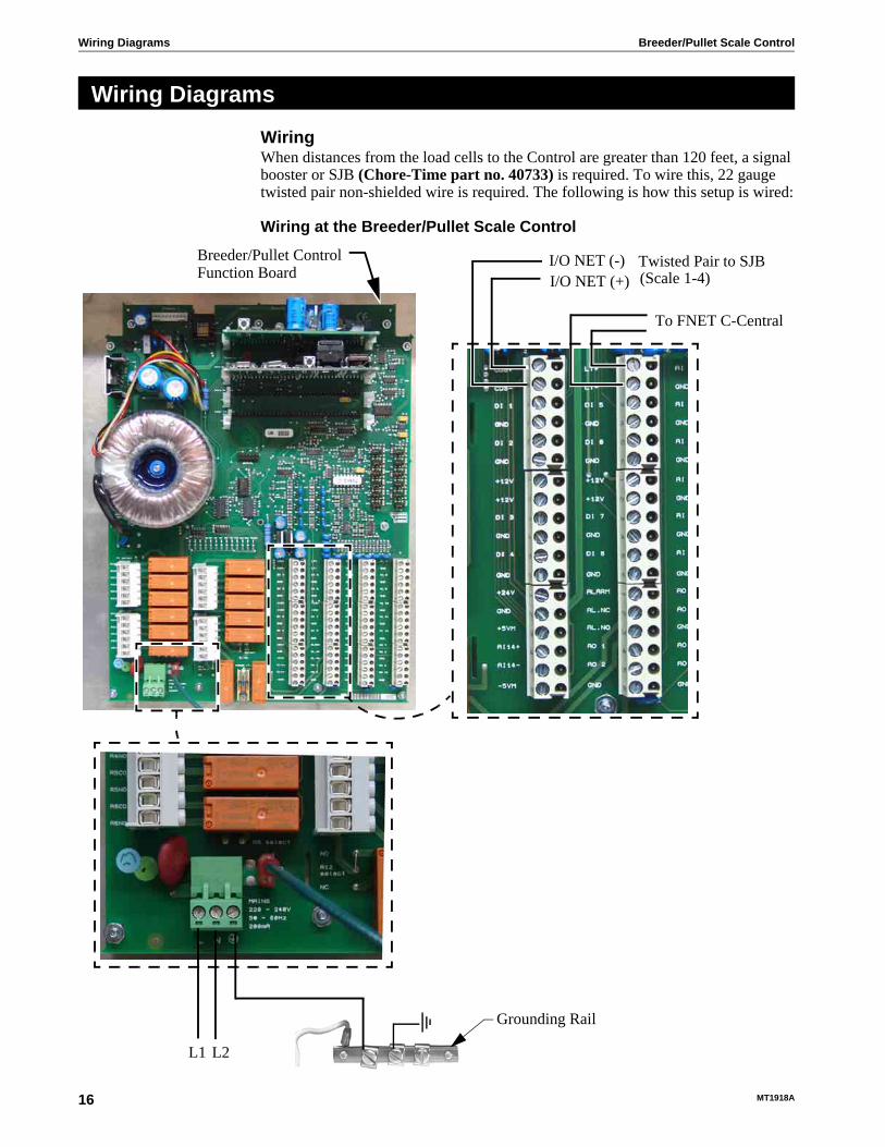
WiringWhen distances from the load cells to the Control are greater than 120 feet, a signal booster or SJB (Chore-Time part no. 40733) is required. To wire this, 22 gauge twisted pair non-shielded wire is required. The following is how this setup is wired:
Wiring at the Breeder/Pullet Scale Control
Wiring Diagrams
Breeder/Pullet ControlFunction Board
Twisted Pair to SJB
Grounding Rail
(Scale 1-4)I/O NET (-)I/O NET (+)
L1 L2
To FNET C-Central

Breeder/Pullet Scale Control Wiring Diagrams
MT1918A 17
Wiring at the Load Cell:
Wiring at the SJB:
LoadCell Shield
BlackBlue
RedBrown
GreenWhite
Insert a small screw driverand press while insertingwires to lock into place.
24 Volt to Scale
I/O Net to Scale
BlackBlue
BrownRed
White Green Shield
ON
1 2 3
Dip Switch Position4 5
ON
1 2 3 4 5
SJB
Dip Switch Position
ON
1 2 3 4 5
Dip Switch Positionfor SJB #2 for SJB #1 for SJB #3
ON
1 2 3 4 5
Dip Switch Position for SJB #4
Control #1

Wiring Diagrams Breeder/Pullet Scale Control
18 MT1918A
Sample Wiring Installation

Breeder/Pullet Scale Control PC Connection
MT1918A 19
The Controls in each house are connected together at the FNET Terminal Connectors as shown below. Use only Twisted Pair Wire (Chore-Time Part No. 42208). The Interface Box can be wired in anywhere either at the beginning of your string, at the end, or between Controls; but not to more than one Control as shown below.
PC Connection
FNETConnectionTypical
I/O BoardTypical
PC
Ventilation Control
InterfaceBox
FNETConnectionTypical
I/O BoardTypical
InterfaceBox
Twisted Pair Wire Typical
PC or Modem
or Modem
PC or Modem
9 Pin Serial Cord to PC
9 Pin Serial Cord to PC
Incorrect Installation
Twisted Pair Wire Typical
Breeder/PulletScale Control
Breeder/PulletScale Control
PC C
onnectionB
reeder/Pullet Scale Control
20M
T1918A
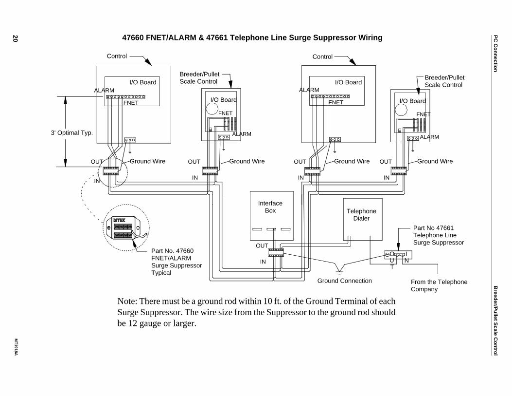
47660 FNET/ALARM & 47661 Telephone Line Surge Suppressor Wiring
ALARM
FNET
N
ALARM
FNET
ALARM
FNET
OUT
IN
OUT
IN
OUT
IN
OUT
IN
Ground Wire Ground Wire Ground Wire Ground Wire
OUT
INIO
UT
I/O Board
I/O Board
I/O Board
Control
Breeder/PulletScale Control
Control
InterfaceBox Telephone
DialerPart No 47661Telephone LineSurge Suppressor
Ground Connection From the TelephoneCompany
Part No. 47660FNET/ALARMSurge SuppressorTypical
3' Optimal Typ.ALARM
FNET
I/O Board
Breeder/PulletScale Control
Note: There must be a ground rod within 10 ft. of the Ground Terminal of eachSurge Suppressor. The wire size from the Suppressor to the ground rod shouldbe 12 gauge or larger.

Breeder/Pullet Scale Control Technical Specifications
MT1918A 21
Ambient Operating Temperature Range...32°F (0°C) to 104°F (40°C)Supply Voltage.........................230 Vac 50-60hz
Maximum Power Consumption...External Power Output
Voltage...............................24 Vdc +/- 1.5VLoad...................................500 mA max.
Sensor Wire / PC Wire.....20 gauge single Twisted Pair Wire, 1 twist every 2 inches, unshielded wire. Use of Chore-Time part number 42208 is strongly recommended.
Load Cell Wire: 22 gauge 6-conductor shielded wire. Use of Chore-Time part no 42208 is strongly recommended.
FNET Data Voltage Range (C-Central).....+/- 5 V
Alarm Relay Voltage.....30 Vac
50 Vdc Current .5A @ 250 Vac
.5A @ 30 Vdc
Technical Specifications

Parts List Breeder/Pullet Scale Control
22 MT1918A
Parts List
Item Description Part No.1 14" x 16" Electric Box 426842 Control Box Latch Pivot 308633 Control Box Latch 308624 Bird Scale Bottom Plate 506045 3.15" Grounding Rail 43384-26 IMC714 PC Board 507157 IMC715 Power Supply 507128 IMC720 CPU Board 507289 Breeder/Pullet Scale Top Plate 5060310 IMC735 Key Board 5071411 4 x 20 LED Display 5070912 Breeder Pullet Scale Wiring Harness 5072013 1" x 1" Aluminum Hinge 4948214 Bird Platform Support 4767115 Load Cell 4872416 J-Hook 121417 Hook, 5/16" Spring Clip 48729
14
1
15 16
17
2 3
4
5
6
78910 11 1213

Breeder/Pullet Scale Control Parts List
MT1918A 23
This page Intentionally left blank.....

Parts List Breeder/Pullet Scale Control
24 MT1918A
Note: The original, authoritative version of this manual is the [English] version produced by CTB, Inc. or any of its subsidiaries or divisions, (hereafter collectively referred to as "CTB"). Subsequent changes to any manual made by any third party have not been reviewed nor authenticated by CTB. Such changes may include, but are not limited to, translation into languages other than [English], and additions to or deletions from the original content. CTB disclaims responsibility for any and all damages, injuries, warranty claims and/or any other claims associated with such changes, inasmuch as such changes result in content that is different from the authoritative CTB-published [English] version of the manual. For current product installation and operation information, please contact the customer service and/or technical service departments of the appropriate CTB subsidiary or division. Should you observe any questionable content in any manual, please notify CTB immediately in writing to: CTB Legal Department, P.O. Box 2000, Milford, IN 46542-2000 USA.
Revisions to this ManualPage No. Description of Change
Contact your nearby C-Collect® distributor or representative for additional parts and information.
CTB Inc.P.O. Box 2000 • Milford, Indiana 46542-2000 • U.S.A.
Phone (574) 658-4101 • Fax (877) 730-8825E-Mail: [email protected] • Internet: http//www.ctbinc.com
Printed in the U.S.A.