brentwood lessons learned project report - nrel.gov · if an electrolyzer is part of the station...
TRANSCRIPT

Brentwood Lessons Learned Project Report Carl Rivkin, Melanie Caton, and Christopher Ainscough National Renewable Energy Laboratory
Jason Marcinkoski U.S. Department of Energy
NREL is a national laboratory of the U.S. Department of Energy Office of Energy Efficiency & Renewable Energy Operated by the Alliance for Sustainable Energy, LLC
This report is available at no cost from the National Renewable Energy Laboratory (NREL) at www.nrel.gov/publications.
Technical Report NREL/TP-5400-68769 September 2017
Contract No. DE-AC36-08GO28308

NREL is a national laboratory of the U.S. Department of Energy Office of Energy Efficiency & Renewable Energy Operated by the Alliance for Sustainable Energy, LLC
This report is available at no cost from the National Renewable Energy Laboratory (NREL) at www.nrel.gov/publications.
Contract No. DE-AC36-08GO28308
National Renewable Energy Laboratory 15013 Denver West Parkway Golden, CO 80401 303-275-3000 • www.nrel.gov
Brentwood Lessons Learned Project Report Carl Rivkin, Melanie Caton, and Christopher Ainscough National Renewable Energy Laboratory
Jason Marcinkoski U.S. Department of Energy
Prepared under Task No. HT12.8854
Technical Report NREL/TP-5400-68679 September 2017

NOTICE
This report was prepared as an account of work sponsored by an agency of the United States government. Neither the United States government nor any agency thereof, nor any of their employees, makes any warranty, express or implied, or assumes any legal liability or responsibility for the accuracy, completeness, or usefulness of any information, apparatus, product, or process disclosed, or represents that its use would not infringe privately owned rights. Reference herein to any specific commercial product, process, or service by trade name, trademark, manufacturer, or otherwise does not necessarily constitute or imply its endorsement, recommendation, or favoring by the United States government or any agency thereof. The views and opinions of authors expressed herein do not necessarily state or reflect those of the United States government or any agency thereof.
This report is available at no cost from the National Renewable Energy Laboratory (NREL) at www.nrel.gov/publications.
Available electronically at SciTech Connect http:/www.osti.gov/scitech
Available for a processing fee to U.S. Department of Energy and its contractors, in paper, from:
U.S. Department of Energy Office of Scientific and Technical Information P.O. Box 62 Oak Ridge, TN 37831-0062 OSTI http://www.osti.gov Phone: 865.576.8401 Fax: 865.576.5728 Email: [email protected]
Available for sale to the public, in paper, from: U.S. Department of Commerce National Technical Information Service 5301 Shawnee Road Alexandria, VA 22312 NTIS http://www.ntis.gov Phone: 800.553.6847 or 703.605.6000 Fax: 703.605.6900 Email: [email protected]
Cover Photos by Dennis Schroeder: (left to right) NREL 26173, NREL 18302, NREL 19758, NREL 29642, NREL 19795.
NREL prints on paper that contains recycled content.

iii This report is available at no cost from the National Renewable Energy Laboratory at www.nrel.gov/publications.
Acknowledgments This report is being produced as part of the Brentwood Lessons Learned project. Funding for this work was provided by the U.S. Department of Energy’s Fuel Cell Technologies Office in the Office of Energy Efficiency and Renewable Energy.
NREL would like to thank the following key contributors:
• John Christensen, P.E., Consultant to the U.S. Department of Energy
• Peter Devlin, Technology Development Manager, U.S. Department of Energy.

iv This report is available at no cost from the National Renewable Energy Laboratory at www.nrel.gov/publications.
List of Acronyms AHJ authority having jurisdiction DOE U.S. Department of Energy FCEV fuel cell electric vehicle ISO International Organization for Standardization NPS National Park Service NREL National Renewable Energy Laboratory OEM original equipment manufacturer RFP request for proposals

v This report is available at no cost from the National Renewable Energy Laboratory at www.nrel.gov/publications.
Executive Summary The purpose of this report is to document lessons learned in the installation of the hydrogen fueling station at the National Park Service Brentwood site in Washington, D.C., to help further the deployment of hydrogen infrastructure required to support hydrogen and other fuel cell technologies. Hydrogen fueling is the most difficult infrastructure component to build and permit. Hydrogen fueling can include augmenting hydrogen fueling capability to existing conventional fuel fueling stations as well as building brand new hydrogen fueling stations.
This report was produced as a part of the Brentwood Lessons Learned project. The project consisted of transplanting an existing modular hydrogen fueling station from Connecticut to the National Park Service Brentwood site. This relocation required design and construction at the Brentwood site to accommodate the existing station design as well as installation and validation of the updated station.
One of the most important lessons learned was that simply moving an existing modular station to an operating site was not necessarily straight-forward—performing the relocation required significant effort and cost. The station has to function at the selected operating site and this functionality requires a power supply, building supports connecting to an existing alarm system, electrical grounding and lighting, providing nitrogen for purging, and providing deionized water if an electrolyzer is part of the station package. Most importantly, the station has to fit into the existing site both spatially and operationally and not disrupt existing operations at the site. All of this coordination and integration requires logistical planning and project management. The idea that a hydrogen fueling station can be simply “dropped” onto a site and made immediately operational is generally not realistic.
Other important lessons learned include the following:
• Delineating the boundaries of the multiple jurisdictions that have authority over a project for all parties involved in the project are key to an efficient approval process.
• Site investigation is necessary when integrating a new station design onto an existing site, particularly an older existing site that may have limited documentation on the site history and operations.
The lessons learned for permitting and subcontracting construction work can be applied to other similar sites and to commercial sites.

vi This report is available at no cost from the National Renewable Energy Laboratory at www.nrel.gov/publications.
Table of Contents 1 Introduction ........................................................................................................................................... 1 2 Background ........................................................................................................................................... 2 3 Project Timeline and Partners ............................................................................................................. 3 4 Hydrogen Fueling Station Details ....................................................................................................... 4 5 Lessons Learned .................................................................................................................................. 9
5.1 Permitting ...................................................................................................................................... 9 5.2 Project Management .................................................................................................................... 11 5.3 Site Selection ............................................................................................................................... 12 5.4 Site Utilization............................................................................................................................. 12 5.5 Construction ................................................................................................................................ 13 5.6 Infrastructure Deployment Cost .................................................................................................. 13
6 Conclusions and Future Work .......................................................................................................... 14 Appendix: Site Evaluation and Code Compliance Check Sheets ........................................................ 16

vii This report is available at no cost from the National Renewable Energy Laboratory at www.nrel.gov/publications.
List of Figures Figure 1. Overview schematic of hydrogen fueling system. Figure from Proton OnSite ............................ 4 Figure 2. Front schematic of hydrogen fueling system. Figure from Proton OnSite ................................... 5 Figure 3. Back schematic of hydrogen fueling system. Figure from Proton OnSite .................................... 6 Figure 4. Photo of the installed hydrogen fueling station at the Brentwood site .......................................... 7 Figure 5. Required setback distances. Figure from Proton OnSite ............................................................. 10 Figure 6. Location of fire alarm pull box. Figure from Proton OnSite....................................................... 11 Figure 7. New grounding required for vehicle fueling ............................................................................... 12 Figure 8. Review of below-grade images required to locate rebar for station fueling pad ......................... 13
List of Tables Table 1. Project Timeline .............................................................................................................................. 3 Table 2. Station Characteristics .................................................................................................................... 7 Table 3. Station Safety Features ................................................................................................................... 8 Table 4. Brentwood Station AHJs................................................................................................................. 9 Table 5. Items that Could Impact Project Cost ........................................................................................... 14
1 This report is available at no cost from the National Renewable Energy Laboratory at www.nrel.gov/publications.
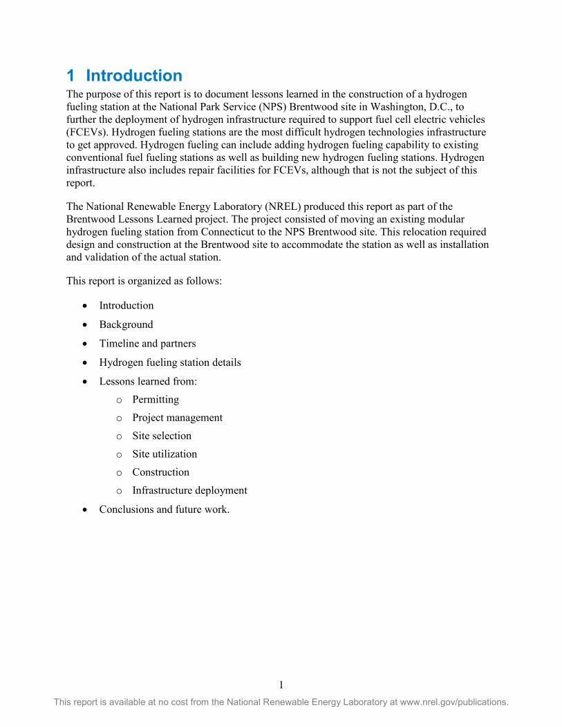
1 Introduction The purpose of this report is to document lessons learned in the construction of a hydrogen fueling station at the National Park Service (NPS) Brentwood site in Washington, D.C., to further the deployment of hydrogen infrastructure required to support fuel cell electric vehicles (FCEVs). Hydrogen fueling stations are the most difficult hydrogen technologies infrastructure to get approved. Hydrogen fueling can include adding hydrogen fueling capability to existing conventional fuel fueling stations as well as building new hydrogen fueling stations. Hydrogen infrastructure also includes repair facilities for FCEVs, although that is not the subject of this report.
The National Renewable Energy Laboratory (NREL) produced this report as part of the Brentwood Lessons Learned project. The project consisted of moving an existing modular hydrogen fueling station from Connecticut to the NPS Brentwood site. This relocation required design and construction at the Brentwood site to accommodate the station as well as installation and validation of the actual station.
This report is organized as follows:
• Introduction
• Background
• Timeline and partners
• Hydrogen fueling station details
• Lessons learned from: o Permitting
o Project management
o Site selection
o Site utilization
o Construction
o Infrastructure deployment
• Conclusions and future work.

2 This report is available at no cost from the National Renewable Energy Laboratory at www.nrel.gov/publications.
2 Background The basic objective of the Brentwood Lessons Learned project is to assist in the development of hydrogen infrastructure. Before permitting and building any hydrogen fueling station, the project team must define some basic parameters. These parameters include the type of station and the station location.
The U.S. Department of Energy (DOE) Fuel Cell Technologies Office developed a Memorandum of Understanding with the National Park Service (NPS) to allow DOE to use the NPS Brentwood Washington, D.C., location for the hydrogen fueling station. DOE, through existing agreements, decided to relocate a Proton OnSite hydrogen fueling station from Wallingford, Connecticut, to the NPS Brentwood site. This station employs an electrolyzer to generate hydrogen on site and requires a dedicated high voltage line to power the electrolyzer. It has a hydrogen storage capacity of approximately 46 kilograms.
NREL’s involvement in the project began approximately in June 2015. NREL was assigned the following tasks:
1. Write a subcontract and act as technical monitor for the design of the construction required to support the hydrogen fueling station at the NPS Brentwood site.
2. Write a subcontract and act as technical monitor for the construction required to install the hydrogen fueling station at the Brentwood site.
3. Write a subcontract and act as technical monitor for the installation of the hydrogen fueling station at the Brentwood site.
4. Write a subcontract and act as technical monitor for the station operation.
5. Assist in permitting for the tasks covered in the subcontracts.

3 This report is available at no cost from the National Renewable Energy Laboratory at www.nrel.gov/publications.
3 Project Timeline and Partners Table 1 shows the timeline for the project and the associated partner activities. These activities are the major milestones in the station construction and commissioning. Note that the original estimate for completing the project differed from the actual time to complete the project by about four weeks. Most of this additional time was a result of delays in completing the site access agreement and the Memorandum of Understanding between DOE and NPS. Although a commercial project would not have these same issues, there could be similar issues that could delay a commercial project. For example, there could be restrictions in site leases on the types of activities that would be allowed at the site that would have to be modified before the project could proceed.
Table 1. Project Timeline
Date Activity
11/23/15 Letter to DOE and NPS for signature
11/25/15 Award and execute contract for design package
1/6/16 Complete design package review (tentative)
1/26/16 Release RFP for construction
2/9/16 Review and select construction contractor (in process)
3/4/16 Execute contract for construction (or reissue RFP)
3/18/16 Execute contract for construction (or reissue RFP)
3/28/16 Ship equipment for delivery
4/4/16 Complete site preparation
4/5/16 Perform final inspections
4/6/16 Proton work begins
4/27/16 Station operational and ready for OEM validation
5/21/16 Soft opening for the Bio Blitz
7/13/16 Official opening at Sustainable Transportation Summit RFP: request for proposals OEM: original equipment manufacturer

4 This report is available at no cost from the National Renewable Energy Laboratory at www.nrel.gov/publications.
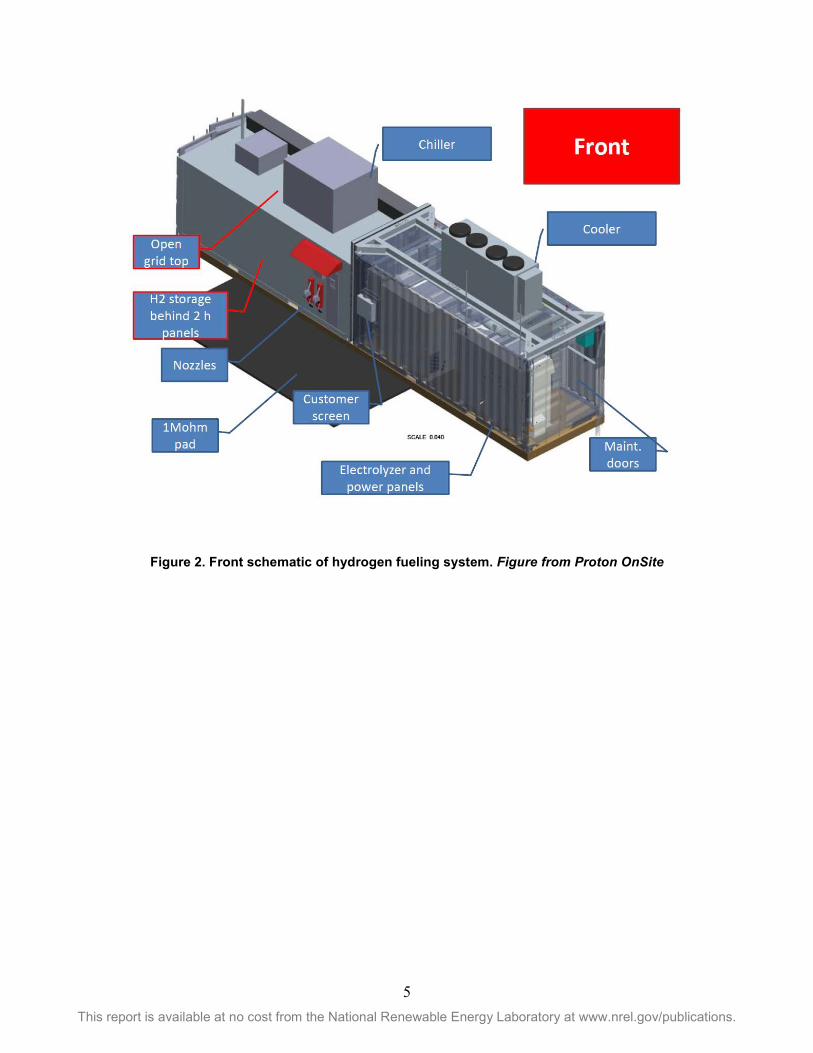
4 Hydrogen Fueling Station Details The hydrogen fueling station selected for installation at the Brentwood site is a Proton electrolyzer design. The station consists of two ISO containers. One ISO container holds the electrolyzer and is closed on top. The second container holds the hydrogen storage, compression, and dispensing units and has an open grid on top. Figures 1–3 show the system from different views. Figure 4 shows a photograph of the installed station.
Table 2 gives station parameters and utility requirements. Table 3 gives information on the station safety systems.
Figure 1. Overview schematic of hydrogen fueling system. Figure from Proton OnSite
5 This report is available at no cost from the National Renewable Energy Laboratory at www.nrel.gov/publications.
Figure 2. Front schematic of hydrogen fueling system. Figure from Proton OnSite

6 This report is available at no cost from the National Renewable Energy Laboratory at www.nrel.gov/publications.
Figure 3. Back schematic of hydrogen fueling system. Figure from Proton OnSite

7 This report is available at no cost from the National Renewable Energy Laboratory at www.nrel.gov/publications.
Figure 4. Photo of the installed hydrogen fueling station at the Brentwood site
Table 2. Station Characteristics
Station Design Parameters
Packaged into two ISO containers
Fuels less than eight cars per day
Total storage is 46 kilograms hydrogen
Electrolyzer capable of generating 43 kilograms hydrogen per day
Dispenser built into ISO container
Dispenser can accept both credit cards and designated user pin numbers
Station has both H70 and H35 dispensing hoses capable of completing a fill in approximately 5 minutes
NPS Utilities Serving Station
NPS has 480 volt, 3 phase, 600 amp metered service for the electrolyzer
Electrical disconnect outside of NPS repair facility directly opposite the dispenser
NPS has metered potable water
Proton will have a 2,400 psi nitrogen cylinder delivered to the site to purge fueling system as needed and keep the electrolyzer container dry (located at cylinder area opposite station)
Fire alarm manual pull box
Emergency stop device located at NPS building opposite dispenser

8 This report is available at no cost from the National Renewable Energy Laboratory at www.nrel.gov/publications.
Table 3. Station Safety Features
Location Emergency Sensors and Alarms
Emergency Response – Chemical Sensor
Emergency Response – Infrared Detector and Linear Heat Wire Detector
Electrolyzer container
Hydrogen detector in electrolyzer and air vent Infrared detector Ventilation anemometer to determine if air flow is adequate
Sensor at electrolyzer, storage, and dispensera
If infrared detector sees hydrogen: station shutdown
Compression, storage, and dispenser container
Hydrogen detector at dispenser and compressor Infrared detector at storage Linear heat wire on plumbing
Flashing strobe light at site
Flashing strobe and horn activated
Fire panel
Fire panel manages alarms/hydrogen detection:
• Strobe light • Equipment stops
operating and hydrogen valves shut
• Service called
Station automatically shuts down in safe mode:
• Storage valves shut and isolate hydrogen
• Dispenser stops and vents any hydrogen in line through stack
• Electrolyzer shuts down
Station automatically shuts down in safe mode:
• Storage valves shut and isolate hydrogen
• Dispenser stops and vents any hydrogen in line through stack
• Fire panel calls NPS panel/first responders
• Personnel evacuate the area
• Fire company secures power on approach lane
a Leak detection and response at 50% of lower flammability limit (LFL)
9 This report is available at no cost from the National Renewable Energy Laboratory at www.nrel.gov/publications.
5 Lessons Learned This section presents lessons learned from permitting, project management, site selection, site utilization, construction, and infrastructure deployment for the hydrogen fueling station at the NPS Brentwood site.
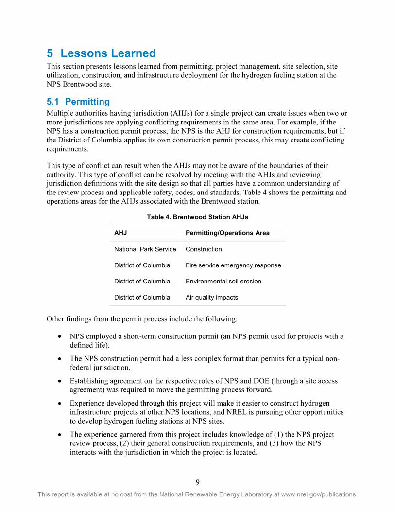
5.1 Permitting Multiple authorities having jurisdiction (AHJs) for a single project can create issues when two or more jurisdictions are applying conflicting requirements in the same area. For example, if the NPS has a construction permit process, the NPS is the AHJ for construction requirements, but if the District of Columbia applies its own construction permit process, this may create conflicting requirements.
This type of conflict can result when the AHJs may not be aware of the boundaries of their authority. This type of conflict can be resolved by meeting with the AHJs and reviewing jurisdiction definitions with the site design so that all parties have a common understanding of the review process and applicable safety, codes, and standards. Table 4 shows the permitting and operations areas for the AHJs associated with the Brentwood station.
Table 4. Brentwood Station AHJs
AHJ Permitting/Operations Area
National Park Service Construction
District of Columbia Fire service emergency response
District of Columbia Environmental soil erosion
District of Columbia Air quality impacts
Other findings from the permit process include the following:
• NPS employed a short-term construction permit (an NPS permit used for projects with a defined life).
• The NPS construction permit had a less complex format than permits for a typical non-federal jurisdiction.
• Establishing agreement on the respective roles of NPS and DOE (through a site access agreement) was required to move the permitting process forward.
• Experience developed through this project will make it easier to construct hydrogen infrastructure projects at other NPS locations, and NREL is pursuing other opportunities to develop hydrogen fueling stations at NPS sites.
• The experience garnered from this project includes knowledge of (1) the NPS project review process, (2) their general construction requirements, and (3) how the NPS interacts with the jurisdiction in which the project is located.

10 This report is available at no cost from the National Renewable Energy Laboratory at www.nrel.gov/publications.
• This NPS site did not require compliance with building and fire codes through their short-term construction permit; however, due diligence indicated a compliance evaluation against NFPA 2 Hydrogen Technologies Code (the primary national code for hydrogen fueling stations).
• NREL developed a compliance check sheet (shown in the Appendix) to facilitate the NFPA 2 compliance analysis. Figure 5 shows how the Brentwood site complies with setback distances. Figure 6 shows the location of the fire alarm pull box.
Figure 5. Required setback distances. Figure from Proton OnSite

11 This report is available at no cost from the National Renewable Energy Laboratory at www.nrel.gov/publications.
Figure 6. Location of fire alarm pull box. Figure from Proton OnSite
5.2 Project Management The project brought out several project management issues. These issues included the following:
• Having multiple partners with different levels of project investment created issues with synchronization and direction on applicable safety, codes, and standards as well as inspection requirements.
• The first-time nature of the project made the development of accurate cost estimates challenging.
• Construction contractors had very limited experience with hydrogen technologies (although much of the construction work for a hydrogen project is not unique to hydrogen).
These last two issues will likely be resolved as hydrogen infrastructure technology moves forward and construction companies gain more experience. The first issue is best addressed by holding an early project meeting at which all parties agree to their responsibilities, and then documenting these agreements.
12 This report is available at no cost from the National Renewable Energy Laboratory at www.nrel.gov/publications.
5.3 Site Selection Taking some relatively simple due-diligence-type steps during a site evaluation can identify major issues and eliminate unsuitable sites. Site issues that should be considered during the site selection process include:
• Contamination, particularly from leaked hydrocarbon fuels
• Construction impacts on existing utilities, particularly buried lines
• Setbacks for hydrogen storage
• Neighboring properties and activities
• Site history—for example, whether the neighbors consider the existing site activities to be a nuisance; soil conditions; and utilities available.
The site selection check sheet in the Appendix goes into more detail on how to screen sites.
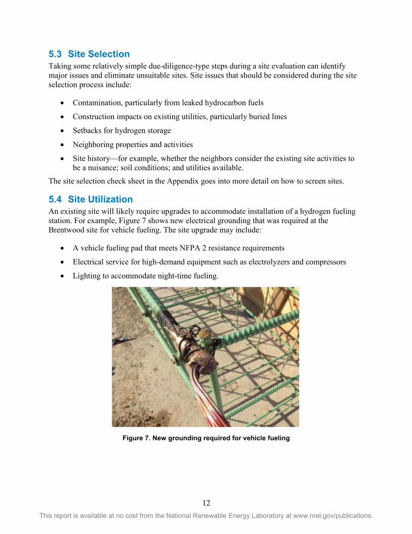
5.4 Site Utilization An existing site will likely require upgrades to accommodate installation of a hydrogen fueling station. For example, Figure 7 shows new electrical grounding that was required at the Brentwood site for vehicle fueling. The site upgrade may include:
• A vehicle fueling pad that meets NFPA 2 resistance requirements
• Electrical service for high-demand equipment such as electrolyzers and compressors
• Lighting to accommodate night-time fueling.
Figure 7. New grounding required for vehicle fueling

13 This report is available at no cost from the National Renewable Energy Laboratory at www.nrel.gov/publications.
5.5 Construction The selected site may require the following construction work to accommodate hydrogen fueling:
• Rerouting conduit to avoid transit through likely asbestos-containing materials
• Additional structural support for large components
• Remediation of soil resulting from solvent usage or fueling operations
• Fire panel upgrade and/or repairs
• Electrical upgrades or repairs to comply with new safety, codes, and standards. These upgrades could include upgrading the existing building grounding system.
This project required the rerouting of conduit to avoid disturbing asbestos, structural support for the fueling pad, electrical panel upgrade, and fire panel repair, reprogramming, and rewiring to comply with NFPA 72 as interpreted by the DC Fire Marshal. The project also required adding rebar to provide structural support for the vehicle fueling pad as shown in Figure 8.
Remediation of contaminated soil or asbestos-containing materials could be very expensive procedures that should be identified at the site screening phase.
Figure 8. Review of below-grade images required to locate rebar for station fueling pad
5.6 Infrastructure Deployment Cost Hydrogen infrastructure can be expensive. A more realistic cost assessment for hydrogen infrastructure that accounts for the cost of delays and routine activities that are part of construction projects would be beneficial for planning and decision making.
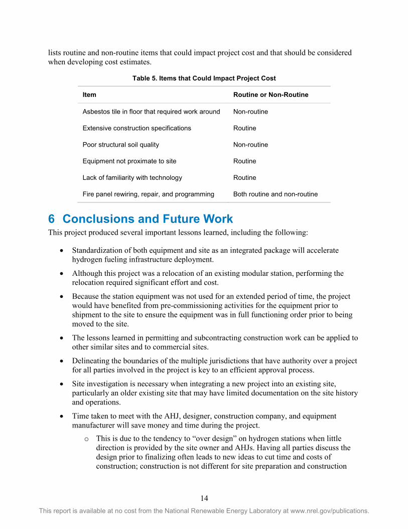
For example, meeting the construction specifications that are part of any project is a major effort that might not have been considered in what appeared to be a small construction project. Table 5
14 This report is available at no cost from the National Renewable Energy Laboratory at www.nrel.gov/publications.
lists routine and non-routine items that could impact project cost and that should be considered when developing cost estimates.
Table 5. Items that Could Impact Project Cost
Item Routine or Non-Routine
Asbestos tile in floor that required work around Non-routine
Extensive construction specifications Routine
Poor structural soil quality Non-routine
Equipment not proximate to site Routine
Lack of familiarity with technology Routine
Fire panel rewiring, repair, and programming Both routine and non-routine
6 Conclusions and Future Work This project produced several important lessons learned, including the following:
• Standardization of both equipment and site as an integrated package will accelerate hydrogen fueling infrastructure deployment.
• Although this project was a relocation of an existing modular station, performing the relocation required significant effort and cost.
• Because the station equipment was not used for an extended period of time, the project would have benefited from pre-commissioning activities for the equipment prior to shipment to the site to ensure the equipment was in full functioning order prior to being moved to the site.
• The lessons learned in permitting and subcontracting construction work can be applied to other similar sites and to commercial sites.
• Delineating the boundaries of the multiple jurisdictions that have authority over a project for all parties involved in the project is key to an efficient approval process.
• Site investigation is necessary when integrating a new project into an existing site, particularly an older existing site that may have limited documentation on the site history and operations.
• Time taken to meet with the AHJ, designer, construction company, and equipment manufacturer will save money and time during the project.
o This is due to the tendency to “over design” on hydrogen stations when little direction is provided by the site owner and AHJs. Having all parties discuss the design prior to finalizing often leads to new ideas to cut time and costs of construction; construction is not different for site preparation and construction

15 This report is available at no cost from the National Renewable Energy Laboratory at www.nrel.gov/publications.
companies can provide extremely useful input to reduce costs of achieving the goal of the design.
Future work could include:
• Sharing this report through the H2Tools portal to assist other hydrogen fueling station projects
• Developing hydrogen fueling station projects at other NPS locations
• Developing a tool for siting hydrogen infrastructure that includes lessons learned from this project such as the impact of potential site contamination and the importance of a clearly delineated set of responsibilities for the AHJs
• Sharing the lessons learned from this project with key organizations involved in infrastructure deployment, such as the National Association of Convenience Store Operators
• Developing and deploying targeted outreach materials for emergency responders, project developers, and potential project investors.

16 This report is available at no cost from the National Renewable Energy Laboratory at www.nrel.gov/publications.
Appendix: Site Evaluation and Code Compliance Check Sheets The following check sheets can be used to evaluate potential hydrogen fueling station sites and determine whether the hydrogen fueling station complies with the NFPA 2 Hydrogen Technologies Code.

17 This report is available at no cost from the National Renewable Energy Laboratory at www.nrel.gov/publications.
Hydrogen Fueling Station Site Evaluation Check Sheet Issue Information Mitigation Notes
History of community actions on construction projects
Have construction projects failed to make it through the various approval processes as a result of community objections or the restrictive application of zoning or other local ordinances?
Meet with building and planning officials to determine the issues that have prevented approval of earlier projects.
Evaluate the value of building in the jurisdiction versus another jurisdiction.
Site ownership Are there any contractual issues with leases or other contracts that would restrict either the construction or operation of a hydrogen fueling station?
Attempt to resolve any legal barrier to building and operating on the site quickly. If this resolution cannot be achieved quickly then alternate sites should be considered.
Site history Has there been solvent, fuel, or other chemical usage at the site?
Were these chemicals used before U.S. Environmental Protection Agency rules on hazardous waste disposal were in effect?
Have there been any serious accidents at the site that may indicate ongoing problems that could affect the project?
Review available environmental compliance documents.
Review any Phase I or II environmental audits.

18 This report is available at no cost from the National Renewable Energy Laboratory at www.nrel.gov/publications.
Site construction Are there constraints on construction such as underground utility lines or environmental restrictions?
Obtain as much information as is readily available to characterize site. Recent site drawings from earlier construction projects are very informative.
Proximity to sensitive occupancies
Are there schools, day care centers, parks, community centers, churches, or other occupancies that would be of special concern to the community?
Evaluate the location of any of these occupancies and determine whether the station could have any impact.
Make efforts to inform interested parties of the operation to explain the facility impact.
Utility access Are current site utility drawings available including drawings for the fire alarms system?
Tap into existing utilities where this connection would not disrupt existing site operations. Also identify any issues with existing alarms system functionality.
Site access Are there any restrictions on hazardous material transport to the site?
Are there issues with hydrogen tanker truck delivery or mobility at the site?
Identify transit routes to site and major routes that are not available to determine whether site is viable with restrictions.

19 This report is available at no cost from the National Renewable Energy Laboratory at www.nrel.gov/publications.
NFPA 2 Hydrogen Technologies Code Compliance Check Sheet for Key Hydrogen Fueling Station Requirements
Compliance Status
Code Topic NFPA 2 2016 Citation
Requirement
System approvals
10.2.1 Compliance with the code shall be certified by a qualified engineer
Component qualifications
10.3.1.1 The following components shall be listed or approved by the AHJ:
1. Pressure relief devices (PRDs) 2. Pressure gauges 3. Pressure regulators 4. Valves 5. Hoses and hose connections 6. Vehicle fueling connections (nozzles) 7. Electrical equipment used with gaseous
hydrogen systems 8. Gas detection equipment and alarms 9. Hydrogen dispensers 10. Pressure switches 11. Flow meters 12. Breakaway devices 13. Dispenser enclosure
Gaseous storage
7.3.2.3.1.1.1 (a) Storage setback distances between exposures such as lot line, wall openings, and ignition sources
Piping 10.3.1.7.3 Piping shall comply with ASME B31.3 Process Piping
Pressure relief and venting
10.3.1.4.3.1
7.1.17
Pressure relief valves shall meet CGA S-1.3 and vent stacks shall meet CGA G-5.5

20 This report is available at no cost from the National Renewable Energy Laboratory at www.nrel.gov/publications.
Maintenance 7.3.1.2.8
10.3.1.13.4
Maintenance shall be performed annually by a qualified representative of the equipment owner. The maintenance shall include inspection for:
• Physical damage • Leak tightness • Ground system integrity • Vent system operation • Equipment identification • Warning signs • Operator information and training records • Scheduled maintenance and retest records • Alarm operation • Other safety-related features
Scheduled maintenance and retest activities shall be formally documented and records shall be maintained a minimum of 3 years
Dispenser involved in an over pressure incident shall not be returned to service without being checked
Compression 7.1.20.1 Compression equipment shall have pressure relief that limits any compression stage to the maximum allowable working pressure
Dispenser operation
10.3.1.13.1 Dispenser operational safety
Electrical 10.3.1.15 Electrical classified areas at dispenser shall be in accordance with Table 10.3.1.15.1
Fire safety 10.3.1.18
6.11
Portable 20-B:C extinguisher required
A manual fire alarm system shall be provided and the system shall be designed, installed, and maintained in accordance with NFPA 72
Vehicle protection
10.3.1.12 Dispensing system shall be protected against vehicle impact
Safety devices
10.3.1.18.1
10.3.1.17.5
10.3.1.17.7
Dispensing equipment shall have gas detection, leak detection, and flame detection
Emergency Power Off (EPO) at dispenser and 25–75 ft from dispenser H2 isolation valves
H2 isolation valves
Leak testing 10.3.1.10.1 Dispensing system shall be leak tested
Signage 10.3.3.2.2.15 Must have sign that says “STOP MOTOR, NO SMOKING, FLAMMABLE GAS, HYDROGEN HAS NO ODOR”
Dispenser setbacks
10.3.2.3.1.4 Dispenser shall meet setback distances in Table 10.3.2.3.1.4