bridge advisory construction &technology division bridge operations … · members or load...
TRANSCRIPT

BRIDGE ADVISORY Construction &Technology Division Bridge Operations Section
BRIDGE ADVISORY NUMBER: BA-2009-01 DATE: January, 15, 2009 SUBJECT: Load Rating Gusset Plates on Non-Load-Path-Redundant Steel Truss Bridges. ISSUED BY: MDOT Bridge Load Rating Engineer REVIEWED BY: MDOT Bridge Operations Engineer Contact Information: Rebecca Curtis, Bridge Load Rating Engineer, 517-322-1186 or [email protected] The Federal Highway Administration has issued Technical Advisory T5140.29 (1) titled: Load- carrying Capacity Considerations of Gusset Plates in Non-load-path-redundant Steel Truss Bridges. The Advisory is attached. Included with the Federal Technical Advisory was the National Transportation Board Safety Recommendation H-08-1 (2), which is attached. The Federal Technical Advisory makes the following recommendations specific to Non-load-path-redundant Steel Truss Bridges:
• New or replaced non-load-path-redundant steel truss bridges. Bridge owners are strongly encouraged to check the capacity of gusset plates as part of the initial load ratings.
• Future recalculations of load capacity on existing non-load-path-redundant steel truss bridges. Bridge owners are strongly encouraged to check the capacity of gusset plates as part of the load rating calculations conducted to reflect changes in condition or dead load, to make permit or posting decisions, or to account for structural modifications or other alterations that result in significant changes in stress levels.
• Previous load ratings for non-load-path-redundant steel truss bridges. Bridge owners are recommended to review past load rating calculations of bridges which have been subjected to significant changes in stress levels, either temporary or permanent, to ensure that the capacities of gusset plates were adequately considered.
In addition to this FHWA Technical Advisory, the FHWA has released a Bridge Design Guidance Document (3) regarding the analysis of gusset plates and also a general update on the “why” and “how” to retrofit gusset plates. This MDOT Bridge Advisory combines the available information and provides guidance with regards to identifying structures that meet the criteria of the FHWA Technical Advisory, inspection procedures, load rating requirements, and retrofitting procedures for gusset plates.

BA 2009 – 01 -2- January 15, 2009 IDENTIFY STRUCTURES The Federal Technical Advisory identifies three criteria for a bridge to be included under the advisory. The bridge must be a steel truss bridge, non-load-path-redundant and contain gusset plates.
STEEL TRUSS BRIDGE The 2006 Bridge Inspection Reference Manual (4) identifies three types of trusses, grouped according to deck position, as shown in Figure 1.
Figure 1: Through Truss, Pony Truss and Deck Truss Elevations and Cross-Sections
MDOT made direct contact with the local agency bridge owners who have steel deck truss bridges identified in the inspection database. A Bridge Advisory BA 2007-04 (5) was issued based upon the FHWA Technical Advisory 5140.27 (6). Technical Advisory 5140.27 strongly advised the immediate re-inspection of all steel deck-truss bridges with fracture critical members. However, the FHWA Technical Advisory 5140.29 and this Bridge Advisory apply to all configurations of steel trusses.

BA 2009 – 01 -3- January 15, 2009
Trusses are generally considered to be main members, although they may be found as portions of other superstructure types. Arches may include trusses as floor systems or stiffening trusses or in movable bridge spans. In cases such as these, the trusses may or may not be considered primary members. If you believe your agency has a bridge of this design that may be miscoded in the bridge database or have questions whether a truss is a primary load carrying member, please contact Rick Smith, Bridge Inspection Program Manager, 517-322-5715 or [email protected]. NON-LOAD-PATH-REDUNDANT Bridge designs that have four (detailed structural analysis may show that only three members are required to provide load-path-redundancy) or more main load-carrying members or load paths between supports are considered load path redundant. If one member were to fail, the bridge load would likely be redistributed to the other members, and bridge failure may not occur. Most truss structures have only two load paths, the two trusses, and are therefore non-load-path-redundant. Please note that FHWA Technical Advisory 5140.27 referred to “fracture critical members”, while in contrast FHWA Technical Advisory 5140.29 and this MDOT Bridge Advisory refer to “non-load-path-redundant” trusses. This difference in terminology removes the requirement that the member is in tension. GUSSET PLATES Gusset plates are plates that connect multiple members. Gusset plates are not unique to trusses, and may also be found on a variety of bridges including truss, girder-floor beam-stringer, suspension, arch and movable. The FHWA Technical Advisory only addresses the gusset plates located on truss structures. However, the function of a gusset plate is similar in all of these types of structures, and it may be a conservative, but logical, step to apply this advisory to structures other than trusses that contain gusset plates. In truss bridges, there are two types of connections: gusset plates and pin connections. Figure 2 shows a typical gusset plate connection and Figure 3 shows a typical pin connection. The FHWA Technical Advisory only addresses the gusset plate connections. However, the function of a pin connection is similar to a gusset plate, and once again it may be a conservative, but logical, step to apply the load rating recommendations of this advisory to non-load-path-redundant steel truss structures with pinned connections.

BA 2009 – 01 -4- January 15, 2009
Figure 2: Gusset Plate Truss Connection
Figure 3: Pinned Truss Connection FHWA Technical Advisory 5140.29 and this MDOT Bridge Advisory deal with trusses with main load path gusset plate connections. While there are many plates providing a certain amount of connection on a truss, main load path gusset plates connect main members and hold the main members in place at a joint while the non-critical plates provide internal connections for each member. Figure 4 distinguishes gusset plates from other typical plates on a truss.

BA 2009 – 01 -5- January 15, 2009
Figure 4: Typical Plates on a Truss
INSPECTION The FHWA Technical Advisory focuses on design related issues. However, as part of a bridge management program, questions may arise regarding inspections of the gusset plates. This information is considered supplemental to the FHWA Technical Advisory. For questions regarding inspection of gusset plates, contact Rick Smith, Bridge Inspection Program Manager, 517-322-5715 or [email protected]. As either a special investigation in order to perform the load rating or as part of an in-depth bridge inspection, the gusset plates should be inspected. Inspection procedures will need to follow the FHWA Inspection of Fracture Critical Bridge Members, Section 4, (7) and AASHTO Guide Manual for Condition Evaluation of Highway Bridges, Section 4, (8) in-depth procedures for close-up inspection of the elements. Verification of the dimensions of the gusset plate size and thickness to the plans will be required as well as fastener count and pitch. In addition, splice plates between the horizontal members may be considered as part of the gusset plate connection. In that case, the splice plate should be checked as well as the gusset plate. There are three main concerns in the inspection of a gusset plate: corrosion, distortion, and connections. Figure 5 identifies the typical locations of the main inspection concerns for gusset plates.

BA 2009 – 01 -6- January 15, 2009
Figure 5: Inspection Concerns for Gusset Plates
CORROSION Corrosion is a loss of material of a steel member due to the chemical process of oxidation. Areas that trap debris or hold water need to be cleaned adequately to evaluate any section losses. Areas with surface rust should be mechanically cleaned and evaluated. Inspect for local pitting, typically found on the outside face of the plate. All section losses should be quantified, the location identified, the area of loss measured and all items documented in the inspection report. The use of ultrasonic thickness gauges or calipers is highly recommended for determining section losses. DISTORTION Overstressing of the gusset plate due to overloads or inadequate bracing may distort the plate. As shown in Figure 5, evaluate the edges of the plate as well as the area located between the compression members for distortion. A straight edge should be used to identify and quantify any distortion of the plate between members. CONNECTIONS Inspect the bolted or riveted connection. Inspect around the individual bolts and rivets to ensure that they are tight and in good condition. Inspect the gusset plate around the bolts or rivets for signs of cracking. Check for cracked, broken, loose or missing rivets, rivet heads or bolts.

BA 2009 – 01 -7- January 15, 2009 ANALYSIS Gusset connections of non-load-path-redundant steel truss bridges shall be evaluated during a bridge load rating analysis. The evaluation of gusset connections shall include the evaluation of the connecting plates and fasteners. The resistance of a gusset connection is determined as the smaller resistance of the fasteners or gusset plates. The following guidance is intended to provide for life safety and thus the resistance of the connection is required to be checked at the strength limit state only. Owners may require that connections be checked at other limit states such as the service limit state to minimize serviceability problems. Load Factor Rating (LFR) or Load and Resistance Factor Rating (LRFR) are both acceptable methods of analyzing gusset plates. The FHWA issued a Memorandum that discusses when LFR or LRFR should be used (9). The following will be a general overview of the current guidelines for the analysis of gusset plates, taken directly from the FHWA Bridge Design Guidance No 1, released by FHWA in 2008, with some modifications based upon MDOT Research Report R-1519 (10). Research projects have been initiated to improve upon current knowledge and methods. Until that time, a sample spreadsheet, “Gusset Plate LFR Analysis.xls” (11) and documentation on the spreadsheet are available on the MDOT website (12).
RESISTANCE OF FASTENERS For concentrically loaded bolted and riveted gusset connections, the axial load in each connected member may be assumed to be distributed equally to all fasteners at the strength limit state. The bolts in bolted gusset connections shall be evaluated to prevent bolt shear and plate bearing failures at the strength limit state. The rivets in riveted gusset connections shall be evaluated to prevent rivet shear and plate bearing failures at the strength limit state. GUSSET PLATES IN TENSION Gusset plates subjected to axial tension shall be investigated for three conditions:
• Yield on the gross section, • Fracture on the net section, and • Block shear rupture
The factored resistance for gusset plates in tension shall be taken as the least of the values given by either yielding, fracture, or the block shear rupture resistance. When determining the gross and net section areas, the effective width of the gusset plate in tension should be determined by the Whitmore method. In this method, the effective width is measured across the last row of fasteners in the connection under consideration. The effective width is bound on either side by the closer of the nearest adjacent plate edges or lines constructed starting from the external fasteners within the first row and extending from these fasteners at an angle of 30 degrees with respect to the line of action of the axial force. The Whitmore width of one member may extend into the influence area of other members. Figures 6a and 6b provide examples for determining the effective width in tension in accordance with the Whitmore method.

BA 2009 – 01 -8- January 15, 2009
Figure 6a: The Whitmore Method for effective width in tension
Figure 6b: The Whitmore Method for effective width in tension
BLOCK SHEAR RUPTURE The resistance to block shear rupture is that resulting from the combined resistance of parallel and perpendicular planes; one in axial tension and the others in shear. The analysis of block shear rupture involves the evaluation of several patterns of planes to arrive at the governing pattern. Figure 7 provides some examples of potential block shear rupture planes for gusset plates in tension.

BA 2009 – 01 -9- January 15, 2009
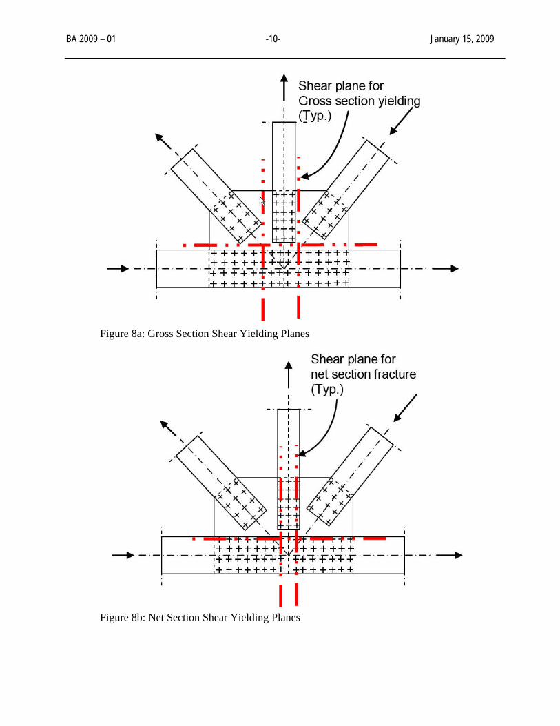
Figure 7: Examples of potential block shear rupture planes GUSSET PLATES IN SHEAR The factored shear resistance for gusset plates subject to shear shall be taken as the lesser of the shear yield and the shear fracture resistance. An additional reduction factor should be included. The reduction factor, O, shall be taken as:
Ω = 1.00 for the case of uniform shear stress distribution where the gusset plates are of ample stiffness to prevent buckling and develop the plastic shear force of the plates, or Ω = 0.74 for the case of flexural shear stress distribution, and in the absence of a more rigorous analysis or criterion to assure and quantify the stiffness requirements to develop the plastic shear force of the plates.
The analysis of gusset plates for shear involves the evaluation of several shear sections to arrive at the governing section. Figures 8a and 8b provide examples of shear sections to be evaluated in gusset plates in gross section shear yielding and net section shear fracture.
BA 2009 – 01 -10- January 15, 2009
Figure 8a: Gross Section Shear Yielding Planes
Figure 8b: Net Section Shear Yielding Planes

BA 2009 – 01 -11- January 15, 2009
GUSSET PLATES IN COMPRESSION The proximity of connected members, complex state of stress, and boundary conditions can influence the resistance of gusset plates in compression. Therefore, special care must be exercised to properly assess the anticipated buckled shape and compressive resistance of gusset plates in compression. In the absence of a more rigorous analysis, the resistance of gusset plates in compression may be determined as that of idealized members in compression. As shown in Figure 9, the effective width of the idealized compression member may be determined in accordance with the Whitmore method. The unbraced length, L
c, may be
determined as the average of three distances (L1, L
2, L
3) as follows:
L2
= The distance from the last row of fasteners in the compression member under consideration to the first row of fasteners in the closest adjacent member, measured along the line of action of the compressive axial force.
L1, L
3 = The distance from each of the ends of the Whitmore width to the first row of fasteners in the closest adjacent member, measured parallel to the line of action of the compressive axial force. When the Whitmore width enters into the adjacent member, the associated distance at that end should be set to zero.
L 2
Whitmore Width
L 3
L 1L 2
Whitmore Width
L 3
L 1
Figure 9: Effective Width and Unbraced Length of Gusset Plate in Compression When lateral sway of gusset plates is possible, the effective length factor, K, for gusset plates may be taken from Table 1 for Cases (d), (e), or (f), depending on the anticipated buckled shape. When lateral sway of gusset plates is not possible, the effective length factor, K, for gusset plates may be taken from Table 2 for Cases (a), (b), or (c), as appropriate.

BA 2009 – 01 -12- January 15, 2009
Buckled shape
(a)
(b)
(c)
(d) (e) (f)
Theoretical K value 0.5 0.7 1.0 1.0 2.0 2.0 Design K value 0.65 0.80 1.0 1.2 2.1 2.0
Table 1: Effective Length Factor, K GUSSET PLATES IN COMBINED FLEXURAL AND AXIAL LOADS According to the FHWA Design Guidance, gusset plates behave as deep members and the application of flexural theory to the analysis of gusset plates is questionable. However, historically combined flexural and axial loads were analyzed. In order to meet the intent of this historic criterion, this check is recommended. The factored resistance for gusset plates subject to combined flexural and axial stresses on the gross area of the plate may be taken as σcrit, where σcrit is the specified minimum buckling strength of a plate (see MDOT Research Report R-1519) or the sample spreadsheet. This value includes resistance factors in the calculation and so further reduction is not required. This analysis is considered to be conservative. The analysis of gusset plates for combined flexural and axial loads involves the evaluation of several sections to arrive at the critical section. Figure 10 provides examples of sections to be evaluated in gusset plates under combined flexure and axial loads. Note that the sections in Figure 10 are placed such that the applied eccentricity is maximized.
Figure 10: Combined Flexural and Axial Load Planes

BA 2009 – 01 -13- January 15, 2009 RETROFITTING GUSSET PLATES During an analysis started as a result of this Bridge Advisory or pursuant to a future bridge inspection, the engineer may determine that a gusset plate requires retrofitting. The FHWA released guidelines for retrofitting gusset plates (13), which are summarized below. Gusset plates should carry a minimum of either the maximum legal load or the maximum load that the other primary members in the structure may carry. If the gusset plate controls the load rating and legal loads are not met, then retrofitting the gusset plate is recommended or load posting is required. Please refer to Chapter 7 of the MDOT Bridge Analysis Guide (14) for Posting Procedures. If the truss or other primary members of the structure control the load rating, then the gusset plates do not require retrofitting and the posting should be based upon the controlling member.
GENERAL GUIDELINES
For gusset plates attached to multiple members (i.e. chord members, diagonal members, struts, and horizontal members), the members should be stabilized prior to removing, replacing or reinforcing the gusset plates as necessary. Adding multiple gusset plates instead of one thick one may be an option when the original gussets are too thin. Removing one gusset plate at a time may be possible. To remove a splice plate (web or flange) decide which should be replaced first. Retrofitting should be done under a “dead load only” condition, if possible. If the dead load carrying capacity of the member is adequate with just the flange plates intact, retrofitting may proceed to replace web plates without external support unless otherwise directed by the engineer. During retrofitting, temporary exterior supports may be necessary. Alternatively, retrofitting may be manageable with tie rods, struts, strong backs or other stabilizing fixtures that are determined to be necessary when the gusset plates are removed. The intent is to isolate the gusset plate connection of all stresses (live load and dead load) so that the plates can be removed and replaced. CORROSION Corrosion may create pitting and section loss. The remaining thickness should be measured and the analysis should be repeated using the measured remaining thickness. If the thickness of the corroded gusset plates will be able to carry the design loads safely and the thickness loss is not severe enough to warrant replacement of gusset plates, recoating of the plates after proper surface preparation will be adequate (e.g. blast cleaning to bare metal). If there is visible packed corrosion between steel gusset plates, the plates should be removed and replaced. If the thickness loss of the corroded gusset plate is so extensive that it will not be able to carry the design loads safely, the thickness loss may warrant replacing the gusset plates. For pin-connected members with corroded or oversized pin holes in gusset plates, stabilize the members in a manner that will transfer the load (away from the pin) to allow removal and replacement of the pin as well as gusset plates, if necessary. As an alternative, the hole may be modified to a larger diameter and a new pin inserted in lieu of replacing the gusset plates.

BA 2009 – 01 -14- January 15, 2009
DISTORTION Distortion (buckling and warping) in gusset plates due to excessive compressive loads,
section loss or the combination of the two may require retrofitting. Yielding and necking in the gusset plates due to excessive tensile loads, section loss or the combination of the two may require retrofitting.
Under certain conditions, bent gusset plates may be repaired by heat-straightening
procedures described in Heat-Straightening Repairs of Damaged Steel Bridges FHWA Report No. FHWA-IF-99-004 (15). As described in the report, the applicable heating patterns will depend on the damage configuration. Heat-straightening repairs can be conducted on gusset plates with maximum plastic strains of less than 100 times the initial yield strain. Such damages in gusset plates may be categorized as mild and repairable by heat straightening. More severely damaged gusset plates should be replaced. Typically, some jacking forces are required as described in the report. A structural analysis may be required to determine whether temporary shoring or stress relief on the gusset may be required.
Caution: heat-straightening repairs of gusset plates are not recommended when member loads have not been transferred away from the joint and the deformation is because of the compressive forces from the members resulting in buckling of the gusset plates. In instances that the edge stresses control the load rating and would require lowering the capacity of the structure and possible vehicle restriction, then stiffeners may be provided to prevent edge buckling without needing to replace the gusset plate. CONNECTIONS
Block Shearing or the tearing of a block of a block of material. Block Shear presumes a combination of a tension rupture and shear yield or a combination of shear rupture and tension yield. Block shear failure is usually associated with bolted details but it can also be present in welded details. Other connection deficiencies may include loose, missing or distorted bolts and rivets, missing nuts and washers/or rivet heads as well as inadequate weld size and/or defects in the weld (e.g. weld cracking, fatigue cracking, and severe undercut, etc.).
Cracked welds or cracks in base metal should be repaired as described in the AWS D1.5 Bridge Welding Code (16). It is conservatively recommended that the criteria in Section 12.17 of the Code on “Repair Welding,” including removal of weld or base metal in preparation for welding, are necessary to correct unacceptable workmanship or damaged materials. For installation of new high-strength bolts refer to the AASHTO LRFD Bridge Construction Specifications.

BA 2009 – 01 -15- January 15, 2009 REFERENCES
1. FHWA (2008). Load-carrying Capacity Considerations of Gusset Plates in Non-load-path-redundant Steel Truss Bridges. T5140.29. Federal Highway Administration. January 15, 2008. http://www.fhwa.dot.gov/legsregs/directives/techadvs/t514029.htm.
2. NTSB (2008). Safety Recommendation. H-08-1. National Transportation Safety Board.
January 15, 2008. Washington, D.C. http://www.ntsb.gov/Recs/letters/2008/H08_1.pdf. 3. Ibrahim, F (2008). FHWA Bridge Design Guidance No 1: Load Rating Evaluation of
Gusset Plates in Truss Bridges. E-mail. Federal Highway Administration.
4. FHWA (2006). Bridge Inspector’s Reference Manual. FHWA NHI 03-001. Federal Highway Administration. http://www.nhi.fhwa.dot.gov/training/course_detail.aspx?num=FHWA-NHI-130055&num=130055
5. MDOT (2007). Immediate Inspection of Deck Truss Bridges Containing Fracture Critical
Members (FCM). BA 2007-04. Michigan Department of Transportation. August 13, 2007. http://www.michigan.gov/documents/mdot/MDOT_BA_2007-04_225804_7.pdf
6. FHWA (2007). Immediate Inspection of Deck Truss Bridges. T5140.27. Federal Highway
Administration. August 15, 2007. http://www.fhwa.dot.gov/bridge/ta514027.cfm.
7. FHWA (1986). Inspection of Fracture Critical Bridge Members. Federal Highway Administration. http://isddc.dot.gov/OLPFiles/FHWA/009349.pdf.
8. AASHTO (2005). Guide Manual for Condition Evaluation and Load and Resistance
Factor Rating (LRFR) of Highway Bridges. American Association of State Highway and Transportation Officials. Washington, D.C.
9. Lwin, M. (2006). INFORMATION: Bridge Load Ratings for the National Bridge Inventory.
Federal Highway Administration. October 30, 2006. http://www.fhwa.dot.gov/bridge/nbis/103006.cfm.
10. Curtis, R., and Till, R. (2008). Critical Buckling Stress for Plates with One Free Edge
Under Combined Axial and Flexural Forces. R-1519. Michigan Department of Transportation.http://www.michigan.gov/documents/mdot/MDOT_Research_Report_R1519_250368_7.pdf.
11. MDOT (2008). Gusset Plate LFR Analysis-V2.0.xls. Michigan Department of
Transportation. Lansing, MI. http://www.michigan.gov/mdot/0,1607,7-151-9625_24768-201633--,00.html.
12. MDOT (2008). Gusset Plate LFR Analysis-V2.0-SAD Michigan Department of
Transportation. Lansing, MI. http://www.michigan.gov/mdot/0,1607,7-151-9625_24768-201633--,00.html.

BA 2009 – 01 -16- January 15, 2009
13. Verma, K. (2008). Retrofitting Gusset Plates and Splice Plates. E-mail. Federal Highway Administration.
14. MDOT (2005). Bridge Analysis Guide. Michigan Department of Transportation. Lansing,
MI. http://www.michigan.gov/mdot/0,1607,7-151-9625_24768_24773-132786--,00.html.
15. FHWA (1998). Heat Straightening Repairs of Damaged Steel Bridges. FHWA-IF-99-004. Federal Highway Administration. http://isddc.dot.gov/OLPFiles/FHWA/009569.pdf.
16. AASHTO/AWS (2008). AWS D1.5 Bridge Welding Code. American Welding Society and
American Association of State Highway and Transportation Officials. Miami, FL.