bridge deflection measurement using …s2is.org/issues/v6/n1/papers/paper3.pdfbridge deflection...
TRANSCRIPT
BRIDGE DEFLECTION MEASUREMENT USING WIRELESS
MEMS INCLINATION SENSOR SYSTEMS
Yan Yu1, Hang Liu1,Dongsheng Li2, Xingquan Mao1, Jinping Ou2
1School of Electronic Science and Technology
Dalian University of Technology,
Dalian, 116024, P.R. China
2School of Civil Engineering
Dalian University of Technology
Dalian, 116024, P.R. China
Emails: [email protected];[email protected]
Submitted: Sep. 17, 2012 Accepted: Jan. 10, 2013 Published: Feb. 20, 2013
Abstract- Bridge is an important part of modern transportation systems and deflection is an important
index for bridge’s safety evaluation. In this paper, a method of deflection measurement using Wireless
MEMS Inclination Sensor Systems (WMISS) is presented and validated. Firstly, based on various
bridge deflection measuring methods, the method of deflection measurement using inclination
parameter is introduced. Secondly, a low-power wireless inclination sensor based on 3D-MEMS SCA60
inclinometer is designed using modularization way, and this kind of wireless sensor loaded with
ZigBee/IEEE 802.15.4 MAC protocol stack can self-organize wireless sensor network, measure the
INTERNATIONAL JOURNAL ON SMART SENSING AND INTELLIGENT SYSTEMS VOL. 6, NO. 1, FEBRUARY 2013
38

angle value and send the data to the coordinator. Then the deflection curve is displayed on PC. Finally,
deflection measurement experiments are conducted on a bridge model and Beida Bridge. The
experimental results show that, the presented deflection measurement method is feasible, practical and
reliable; the wireless inclination sensor is easy to operate with no lines, and has extensive and broad
application prospects.
Index terms: wireless sensor networks, MEMS, deflection measurement, inclination, bridge
I. INTRODUCTION
Bridge is an important component of modern transportation systems. With the rapid development
of national economy, transportation industry in China is booming, which puts forward higher
requirement on the safety of bridge structure. Therefore, safety monitoring is quite necessary. As
science and technology develops, an increasing number of devices are used on bridge monitoring.
Through the analysis of the collected data, people can get knowledge of working conditions of
bridges not only in the past, but also in the future. During this process, deflection is essential.
Deflection is the key technical parameter that judges the vertical stiffness, load-bearing capacity,
and integrality of the bridge. Moreover, it is an important index of bridge detection. Bridges
whose deflections overpass the specified limit of design may increase damage accumulation and
even collapse at any time, which pose a serious threat to people’s lives, and bring about a great
loss of property. Therefore, monitoring the deflections of bridges is indispensable.
In recent years, the number of methods of measuring bridge deflection has been increasing. For
example, measuring the deflection using robot, which has characteristics of high intelligence, fast
measuring speed, large measuring range, high accuracy, and high cost. Another method of
measuring deflection is to take advantage of the photoelectric level of communicating tubes.
Although it has high precision, it is not that easy to implement it because the needed objective
cursor is difficultly decided in practical measurement. A third method is that loading stretching
wires uses displacement sensor to measure deflection. A fourth method is GPS deflection
measurement, in which the precision is the rate of “cm” and the system is expensive. In addition,
there is a method of non-contact optoelectronic measurement based on image processing
technology. Affected by these factors, such as various structures, wide range, huge load, complex
enforced situation, etc, it is necessary to make detailed analysis for different conditions when the
Yan Yu, Hang Liu,Dongsheng Li, Xingquan Mao, Jinping Ou, Bridge Deflection Measurement Using Wireless MEMS Inclination Sensor Systems
39

deflection is being measured. In order to adopt methods suitable for the bridge itself to complete
the deflection measurement, further research should be conducted based on the basic principle,
performance and bridge type. And for most deflection measurement methods, sensor is integrated
into the measurement system by line, which is not convenient for practical engineering.
Fortunately, wireless sensor network technique has been developing rapidly, and is being used
gradually in Structural Health Monitoring for civil engineering structures in an attempt to lower
the high capital costs and rapid installation associated with wire-based structural monitoring
systems [1-5].
Based on the above, wireless inclination deflection measurement is discussed in this paper. A
kind of wireless inclination sensor is designed. Detailed description has been given on hardware
design, software design, system integration, and actual tests.
II. REQUIREMENT OF A CURRENT LIMITER
a. Comparison of current deflection measurement methods
a.i Robot deflection measurement
Surveying robot is a kind of intelligent measurement instrument, which can automatically search,
lock accurately target, and thus record angle, distance, coordinates and image information. The
robot integrates optoelectronics ranging system, electronic measuring angle system, servo motor
drive system, the CCD image sensor, ATR (automatic target recognition) mechanism. Robot
deflection measurement is done by the following steps: First, prism is mounted on the bridge,
and then surveying robot collects geometry information of the prism by measuring robot in
loading respectively before and after the bridge is loaded, finally the corresponding deflection
value is calculated [6].
a.ii Laser image deflection measurement
Laser image deflection measurement is realized by means of the good directionality of laser. The
laser fixed on the bridge creates a laser spot on the stationary optoelectronic receiver, whose
INTERNATIONAL JOURNAL ON SMART SENSING AND INTELLIGENT SYSTEMS VOL. 6, NO. 1, FEBRUARY 2013
40

center moves equivalently as the bridge distorts at different levels. Therefore, bridge deflection is
available as long as the spot center is obtained. When used on deflection measurement, laser
image method is of high-accuracy, which can achieve 0.1mm. Besides, its high sampling rate and
low cost are also suitable for bridges of small and medium size [7].
a.iii GPS deflection measurement
As a generation of satellite navigation and positioning system, GPS (global position system) has
not only global, 24-hour, continuous and precise three-dimensional navigating and positioning
capabilities, but also a good anti-interference and confidentiality. In recent years, precise
positioning technology using GPS on large-span bridge monitoring has drawn wide concern, and
there have already been many examples of successful applications. Its basic principle is: one
receiver (base station) is fixed on the reference point and the other (mobile station) is located
where the most distortion occurs on the bridge, so that both of them can observe more than 4
satellites simultaneously to determine the relative location of the deformation point. Through real
time acquisition of the relative position of the deformation point to the reference point, which
directly reflects the special change of the measured point, the deflection of the bridge structure
can be obtained [8].
a.iv Robot deflection measurement
Using the principle of connecting pipe, the change of bridge deflection can be acquired according
to the liquid level heights in the connecting pipes that are located on various points of the bridge.
In the measuring process, a horizontal pipe should be set along the bridge. On the other hand,
vertical pipes, in which liquid levels maintain the same, are located on the monitoring points
which are also connected with the horizontal one. One vertical pipe has to be set on the shore
base, so that the liquid level in it can be taken as the reference for monitoring. When there is
deformation of the bridge beam, the pipes fixed on it will move together, which can result in
various degrees of changes of the liquid levels in them, although the liquid surfaces in all the
vertical pipes still keep horizontal. The relative displacements obtained in this way are the
deflection values of the measured points [9].
Yan Yu, Hang Liu,Dongsheng Li, Xingquan Mao, Jinping Ou, Bridge Deflection Measurement Using Wireless MEMS Inclination Sensor Systems
41

a.v Electro-optical imaging deflection measurement
Electro-optical imaging deflection measurement is the way in which a target with an optical point
(cursor) on it should be set on the measured point of the bridge. Then the image of the optical
point will be formed on the CCD receiving area-array through the optical system (optical lens).
When there is deflection/displacement of the bridge, the target will shift position. To measure the
variation of the imaging position of the optical point on the CCD and the practical
deflection/displacement value of the bridge could be calculated [10].
a.vi Inclination deflection measurement
Free from the confinement of the site condition such as sunshine, rain, fog and etc, inclination
deflection measurement of bridge deflection monitoring has large measuring range and is capable
to complete one/two-dimensional measurement, which is suitable for deflection measurement of
large/medium-size bridges. Yang and others took advantage of QY inclinometer to conduct the
measurement of static-load deflection on the Songhua River Railway Bridge in Harbin and the
Jiujiang Rail Road Bridge, achieving satisfactory results [11].
Table 1: Shows the comparison of the above deflection measurement methods
Deflection Measurement
Methods Precision
Dynamic / Static measurement
For bridge-type
Cost
Inclination below cm Dynamic / Static Large rigid-frame bridge common
GPS cm Static large-scale bridge expensive
Laser imaging below mm Dynamic / Static Medium or small-scale
bridge expensive
Connection pipe below mm Static any general
Electro-optical
imaging cm/mm Dynamic / Static large-scale bridge
More
expensive
INTERNATIONAL JOURNAL ON SMART SENSING AND INTELLIGENT SYSTEMS VOL. 6, NO. 1, FEBRUARY 2013
42

b. Deflection Measurement Using Inclination Method
b.i Principle
Take simply-supported beam (shown in Figure 1) as the example to work out the relationship
between load and deflection using mechanics of materials, this derivation is based on Euler-
Bernoulli beam theory (i.e. shear deformation is neglected). Since there is a linear relationship
between beam deflection and loads, which obeys Hooke’s Elasticity Law whose coefficients are
related to the stiffness characteristics of the material. The deformation of the beam caused by
each load is unconnected, satisfying the superposition law. Thus the loads can be separated and
the deflection caused by every single load can be calculated.
q
l
p
x
y
Figure 1. Mechanics model of simply-supported bean
Without external load, only gravity loads of the beam itself should be considered and these loads
are uniformly distributed within the whole length of the beam. Suppose the density of the loads is
q (N/m) and the length of the beam is l. Then set up a suitable coordinate system and use
mechanics of materials to derive the equation which can be applied to any point of the beam, the
angle “θ”equation is shown below:
' 3 2 3( 6 4 )24
qy l lx x
EI (1)
EI is a constant, which indicates flexural rigidity of the beam. E is extension-compression elastic
modulus and I is moment of inertia. The deflection value of any point of the beam can be
calculated. And the deflection curve “y” equation is:
3 2 3( 2 )24
qxy l lx x
EI (2)
Yan Yu, Hang Liu,Dongsheng Li, Xingquan Mao, Jinping Ou, Bridge Deflection Measurement Using Wireless MEMS Inclination Sensor Systems
43

The following equations can be obtained from the above ones,Equation 3b is used to get on the
central point of the beam.
3
m ax2 4
q l
E I and
4
m ax
2
5|
384l
x
qly y
EI (3a,b)
Now, the deflection of the bridge is analyzed when only external loads are considered. External
loads are generally applied by vehicles traveling on the bridge. Deflection caused by vehicles is
much lighter than that caused by bridge gravity. As for the simply-supported bridges, the key
point should be focused on the deflection of bridge center. Therefore, the model can be simplified
to carry out the calculation after concentrating the loads on the central point. When external loads
P are all applied on the center, namely, x=l/2, the deflection caused by them is:
223
( ) ( )12 4
px ly x x
EI 0
2
lx ,
2 3
3 29( ) ( 3 )
12 4 4
p l x ly x x lx
EI
2
lx l (4a, b)
According to the superposition principle, the curve equation of the deflection caused by bridge
gravity and external loads is:
22 3 2 33
( ) ( ) ( 2 )12 4 24
px l qxy x x l lx x
EI EI
02
lx
,
2 33 2 3 2 39
( ) ( 3 ) ( 2 )12 4 4 24
p l x l qxy x x lx l lx x
EI EI
2
lx l (5a, b)
The curve reaches its peak on the central point:
3
max
5( )
48 8
l qly p
EI (6)
From the above equations, it is known that the unknown parameters EI of the deflection curve
can be calculated through measuring the slope of the curve, which is angle value. Then, the
deflection curve equation and the deflection of any point are all obtained.
b.ii Implementation of Inclination Deflection Measurement
(1) Single-point Method
In the condition of simple-supported beam without external loads, it can be observed from the
equations above that the angle equation will be obtained through derivation of the deflection one.
INTERNATIONAL JOURNAL ON SMART SENSING AND INTELLIGENT SYSTEMS VOL. 6, NO. 1, FEBRUARY 2013
44

After measuring inclination, the values of the unknown parameters can be got through using its
relationship with inclination, and then the deflection value will be obtained.
(2) Double-point Method
In the condition of simple-supported beam with external loads, the curve of the deflection is
presented by equation (5a, b).
Considering 12
pa
EI
, 24
qb
EI
, and conducting the substitution on the above equations(5a,b) to
get angle equations(7a,b) , the value of a and b, obtained by putting measured angle value into
the equation (7a, b), are input the equation 6 so that deflection value can be obtained. This
method can be applied to the measurements of other points by means of least square method.
2' 2 2 3 33( ) (3 ) (6 4 )
4
ly x x a lx l x b 0
2
lx ,
2' 2 3 2 39( ) ( 3 6 ) ( 6 4 )
4
ly x x lx a l lx x b
2
lx l (7a, b)
III. DESIGN OF WMISS
WMISS consists of wireless inclination sensor nodes and one coordinator connected to a PC
through the serial port. Wireless inclination sensor node is a low power one which completes the
wireless transmission of inclination data through wireless sensor network to achieve the
deflection measurement. The coordinator can finish the functions such as building networks,
receiving and transmitting the data. The same embedded program is preloaded into the wireless
inclination sensor nodes. At the same time, the Labview program is running to work out
deflection on the PC, the structure of the system is shown in Fig. 2.
Yan Yu, Hang Liu,Dongsheng Li, Xingquan Mao, Jinping Ou, Bridge Deflection Measurement Using Wireless MEMS Inclination Sensor Systems
45

Figure 2. Structure of WMISS
a. Hardware Design
Wireless inclination sensor node is developed by the way of module design [12-16], as is shown
in Fig. 3. It consists of inclination sensor based on 3D-MEMS SCA60, micro-process module
MSP430, wireless module cc2520&2591, power module, etc. The coordinator is composed of
micro-process module, wireless module, power module and serial port module.
Figure 3. Modules of wireless inclination sensor node
a.i MEMS SCA60 inclinometer
The SCA60 Series is a 3D-MEMS-based [17] single axis inclinometer family that provides
instrumentation grade performance for leveling applications. Low temperature dependency, high
resolution and low noise, together a with robust sensing element design, make the SCA60 the
ideal choice for leveling instruments. The inclinometers are insensitive to vibration, due to their
over damped sensing elements, and can withstand mechanical shocks of up to 20000 g. SCA60
Node
Sending data
A/D Change
Collecting inclination
Coordinator
Sending order
Trancieving data
Building network
PC
Computing
Reading
Display inclination
wireless serial
INTERNATIONAL JOURNAL ON SMART SENSING AND INTELLIGENT SYSTEMS VOL. 6, NO. 1, FEBRUARY 2013
46
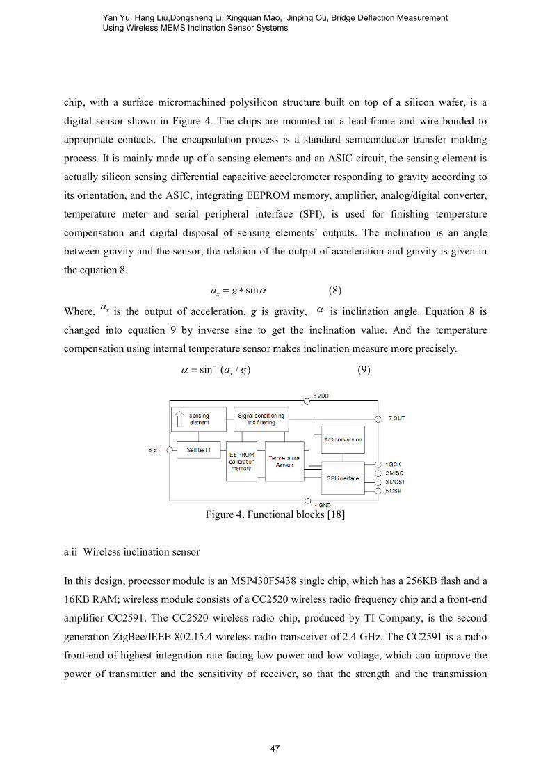
chip, with a surface micromachined polysilicon structure built on top of a silicon wafer, is a
digital sensor shown in Figure 4. The chips are mounted on a lead-frame and wire bonded to
appropriate contacts. The encapsulation process is a standard semiconductor transfer molding
process. It is mainly made up of a sensing elements and an ASIC circuit, the sensing element is
actually silicon sensing differential capacitive accelerometer responding to gravity according to
its orientation, and the ASIC, integrating EEPROM memory, amplifier, analog/digital converter,
temperature meter and serial peripheral interface (SPI), is used for finishing temperature
compensation and digital disposal of sensing elements’ outputs. The inclination is an angle
between gravity and the sensor, the relation of the output of acceleration and gravity is given in
the equation 8,
sinxa g (8)
Where, xa is the output of acceleration, g is gravity, is inclination angle. Equation 8 is
changed into equation 9 by inverse sine to get the inclination value. And the temperature
compensation using internal temperature sensor makes inclination measure more precisely.
1sin ( / )xa g (9)
Figure 4. Functional blocks [18]
a.ii Wireless inclination sensor
In this design, processor module is an MSP430F5438 single chip, which has a 256KB flash and a
16KB RAM; wireless module consists of a CC2520 wireless radio frequency chip and a front-end
amplifier CC2591. The CC2520 wireless radio chip, produced by TI Company, is the second
generation ZigBee/IEEE 802.15.4 wireless radio transceiver of 2.4 GHz. The CC2591 is a radio
front-end of highest integration rate facing low power and low voltage, which can improve the
power of transmitter and the sensitivity of receiver, so that the strength and the transmission
Yan Yu, Hang Liu,Dongsheng Li, Xingquan Mao, Jinping Ou, Bridge Deflection Measurement Using Wireless MEMS Inclination Sensor Systems
47
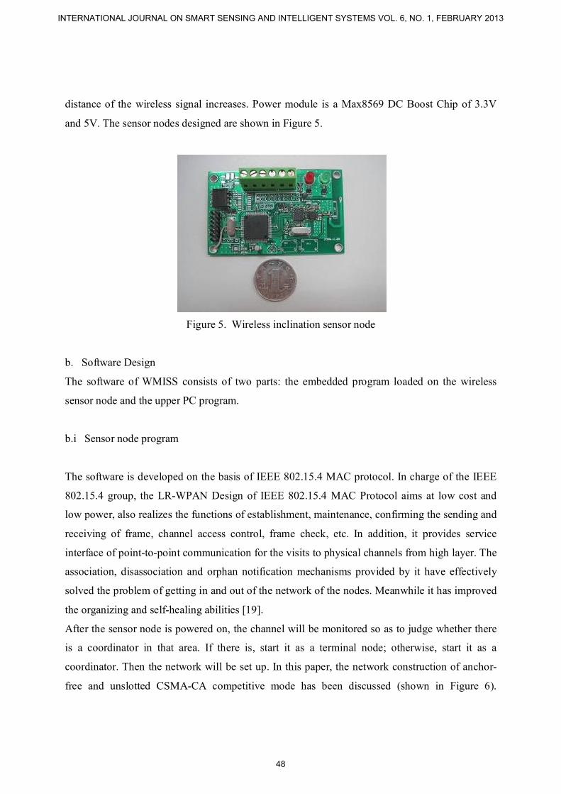
distance of the wireless signal increases. Power module is a Max8569 DC Boost Chip of 3.3V
and 5V. The sensor nodes designed are shown in Figure 5.
Figure 5. Wireless inclination sensor node
b. Software Design
The software of WMISS consists of two parts: the embedded program loaded on the wireless
sensor node and the upper PC program.
b.i Sensor node program
The software is developed on the basis of IEEE 802.15.4 MAC protocol. In charge of the IEEE
802.15.4 group, the LR-WPAN Design of IEEE 802.15.4 MAC Protocol aims at low cost and
low power, also realizes the functions of establishment, maintenance, confirming the sending and
receiving of frame, channel access control, frame check, etc. In addition, it provides service
interface of point-to-point communication for the visits to physical channels from high layer. The
association, disassociation and orphan notification mechanisms provided by it have effectively
solved the problem of getting in and out of the network of the nodes. Meanwhile it has improved
the organizing and self-healing abilities [19].
After the sensor node is powered on, the channel will be monitored so as to judge whether there
is a coordinator in that area. If there is, start it as a terminal node; otherwise, start it as a
coordinator. Then the network will be set up. In this paper, the network construction of anchor-
free and unslotted CSMA-CA competitive mode has been discussed (shown in Figure 6).
INTERNATIONAL JOURNAL ON SMART SENSING AND INTELLIGENT SYSTEMS VOL. 6, NO. 1, FEBRUARY 2013
48

Terminal node sends out net access application to coordinator, and coordinator gives response to
it by sending responding-frame. When the network is successfully constructed, connection
between nodes and coordinator will be built up, after which nodes could compete for channel in
the way of unslotted CSMA-CA competitive mode. When there is a confliction, circumvention
will be made according to the CSMA-CA algorithm. Then the data will be resent. In order to
obtain the ID numbers and AD values of inclination of the nodes, the coordinator makes analysis
after receiving the data. Then it will put them into the buffer zone and send them out.
UnslottedCSMA/CA
NB=0BE=macMinBE
Retreat 0-(2BE-1)cycles
Run CCA
Channel idle?
Visit channel successfully
YNB+1
BE=min
(BE+1,MaxBE)
N
NB>MaxCSMABackoffs
Visit channel with no effect
Y
N
Figure 6. Flow chart of unslotted CSMA-CA
b.ii Program of upper computer based on Labview
The software of upper computer(PC in Fig.2) is realized in Labview:
(1) Configure the parameters of the serial port and initialize;
(2) Use the control to monitor the serial port and read data from it. Separate the character string
into two parts (ID number and inclination value);
(3) Transform the inclination data into corresponding inclination value and calculate the
deflection according to the theories of Material Mechanics;
Yan Yu, Hang Liu,Dongsheng Li, Xingquan Mao, Jinping Ou, Bridge Deflection Measurement Using Wireless MEMS Inclination Sensor Systems
49
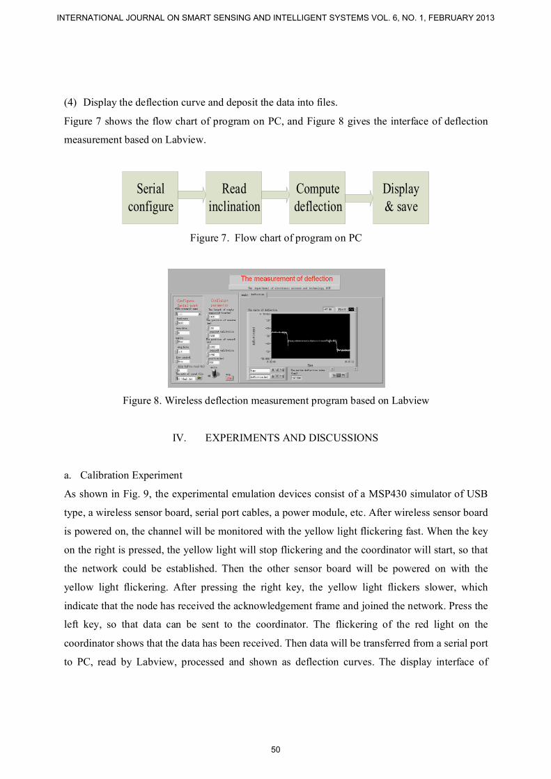
(4) Display the deflection curve and deposit the data into files.
Figure 7 shows the flow chart of program on PC, and Figure 8 gives the interface of deflection
measurement based on Labview.
Serial configure
Read inclination
Computedeflection
Display& save
Figure 7. Flow chart of program on PC
Figure 8. Wireless deflection measurement program based on Labview
IV. EXPERIMENTS AND DISCUSSIONS
a. Calibration Experiment
As shown in Fig. 9, the experimental emulation devices consist of a MSP430 simulator of USB
type, a wireless sensor board, serial port cables, a power module, etc. After wireless sensor board
is powered on, the channel will be monitored with the yellow light flickering fast. When the key
on the right is pressed, the yellow light will stop flickering and the coordinator will start, so that
the network could be established. Then the other sensor board will be powered on with the
yellow light flickering. After pressing the right key, the yellow light flickers slower, which
indicate that the node has received the acknowledgement frame and joined the network. Press the
left key, so that data can be sent to the coordinator. The flickering of the red light on the
coordinator shows that the data has been received. Then data will be transferred from a serial port
to PC, read by Labview, processed and shown as deflection curves. The display interface of
INTERNATIONAL JOURNAL ON SMART SENSING AND INTELLIGENT SYSTEMS VOL. 6, NO. 1, FEBRUARY 2013
50
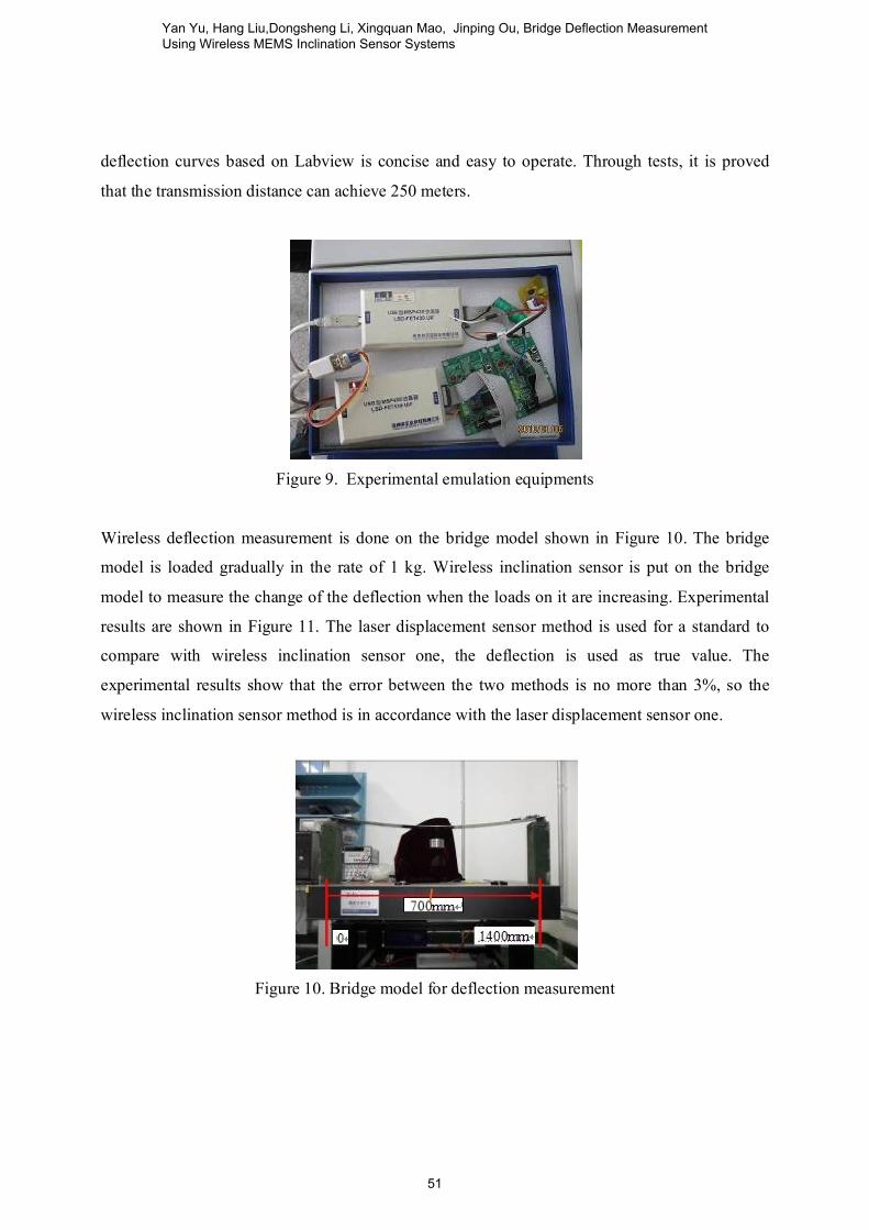
deflection curves based on Labview is concise and easy to operate. Through tests, it is proved
that the transmission distance can achieve 250 meters.
Figure 9. Experimental emulation equipments
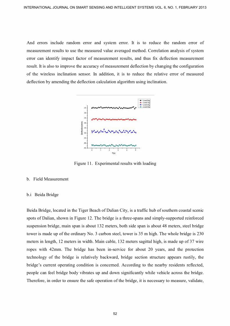
Wireless deflection measurement is done on the bridge model shown in Figure 10. The bridge
model is loaded gradually in the rate of 1 kg. Wireless inclination sensor is put on the bridge
model to measure the change of the deflection when the loads on it are increasing. Experimental
results are shown in Figure 11. The laser displacement sensor method is used for a standard to
compare with wireless inclination sensor one, the deflection is used as true value. The
experimental results show that the error between the two methods is no more than 3%, so the
wireless inclination sensor method is in accordance with the laser displacement sensor one.
Figure 10. Bridge model for deflection measurement
Yan Yu, Hang Liu,Dongsheng Li, Xingquan Mao, Jinping Ou, Bridge Deflection Measurement Using Wireless MEMS Inclination Sensor Systems
51
And errors include random error and system error. It is to reduce the random error of
measurement results to use the measured value averaged method. Correlation analysis of system
error can identify impact factor of measurement results, and thus fix deflection measurement
result. It is also to improve the accuracy of measurement deflection by changing the configuration
of the wireless inclination sensor. In addition, it is to reduce the relative error of measured
deflection by amending the deflection calculation algorithm using inclination.
Figure 11. Experimental results with loading
b. Field Measurement
b.i Beida Bridge
Beida Bridge, located in the Tiger Beach of Dalian City, is a traffic hub of southern coastal scenic
spots of Dalian, shown in Figure 12. The bridge is a three-spans and simply-supported reinforced
suspension bridge, main span is about 132 meters, both side span is about 48 meters, steel bridge
tower is made up of the ordinary No. 3 carbon steel, tower is 35 m high. The whole bridge is 230
meters in length, 12 meters in width. Main cable, 132 meters sagittal high, is made up of 37 wire
ropes with 42mm. The bridge has been in-service for about 20 years, and the protection
technology of the bridge is relatively backward, bridge section structure appears rustily, the
bridge’s current operating condition is concerned. According to the nearby residents reflected,
people can feel bridge body vibrates up and down significantly while vehicle across the bridge.
Therefore, in order to ensure the safe operation of the bridge, it is necessary to measure, validate,
INTERNATIONAL JOURNAL ON SMART SENSING AND INTELLIGENT SYSTEMS VOL. 6, NO. 1, FEBRUARY 2013
52

and repair the bridge. Based on this, the vertical deflection of the bridge’s mid-span is measured
using WMISS.
Figure 12. Beida Bridge
b.i Measurement
Two wireless inclination sensors conducted a zero calibration are respectively put both sides of
Beida Bridge’s midspan. The coordinator and wireless sensor nodes are powered on, the wireless
sensor networks is built using the embedded software, and then the deflection measurement using
WMISS is conducted while there are three buses and some cars across the bridge. The sensor
collocation is shown in Figure 13. Deflection measurement result is shown in Figure 14. With
two sides fulcrum for reference point, the maximum midspan deflection is up to 248.49 mm,
while the value in 2005 is 195 mm and the value in 1995 is 181 mm [20], all these show that the
current deflection of the bridge’s midspan is larger. The large deflection’s change not only
directly influences the bearing capacity of the bridge, but also reduces the driving comfort. The
bridge, with an obvious shock while in a large deflection, makes people produce a kind of not
safe feeling. On the basis of measurement result using WMISS, it is necessary to repair the Beida
Bridge, especially its suspension cable, in order to prevent the deflection from increasing. Now
Beida Bridge’s operation is good after maintenance.
Yan Yu, Hang Liu,Dongsheng Li, Xingquan Mao, Jinping Ou, Bridge Deflection Measurement Using Wireless MEMS Inclination Sensor Systems
53

Figure 13. Sensor collocation
0 5 10 15 20 25 30 35 40
-250
-200
-150
-100
-50
0
Deflect
ion(m
m)
T (s)
Figure 14. Deflection measurement using WMISS
V. CONCLUSIONS
In this paper, a measurement method of deflection using self-designed WMISS is introduced. By
means of measuring inclination and applying mechanics of material, the deflection of structure
can be calculated. The wireless inclination sensor is calibrated on the bridge model to accomplish
the data collection using the MAC Protocol provided by TI Company. The WMISS is applied for
deflection measurement of Beida Bridge of Dalian city, and present the repair project of the
bridge according to the analysis of the measured data. The wireless sensor in this method are
simple and easy to operate, and of high applicability. It represents an important direction for the
development of bridge deflection measurement, which has extensive applicability and broad
application prospects.
In general, the design is preliminary and further improvement is necessary. More importantly,
more tests need to be carried out before it can be of practical use.
INTERNATIONAL JOURNAL ON SMART SENSING AND INTELLIGENT SYSTEMS VOL. 6, NO. 1, FEBRUARY 2013
54

VI. ACKNOWLEGEMENT
Financial supports for this study is provided by grants from the National Nature Science
Foundation of China (Project No.51108060,51161120359,50921001), The natural science
foundation of Liaoning Province (201202039), the National Key Technology Research and
Development Program during the Twelfth Five-Year Plan Period (Project No.2011BAK02B01),
the Fundamental Research Funds for the Central Universities (Project No. DUT12JR13), are
gratefully acknowledged.
REFERENCES
[1] Spencer, B.F, “Opportunities and Challenges for Smart Sensing Technology”, First
International Conference on Structural Health Monitoring and Intelligent Infrastructure, Japan, pp.
65-71, 2003.
[2] Ou J. P. and Li H. W, “Wireless sensor information fusion for structural health monitoring”,
SPIE, Vol.5099, pp. 356-362, 2003.
[3] Yan Yu and Jinping Ou, “Design, calibration and application of wireless sensors for structural
global and local monitoring of civil infrastructures”, Smart Structures and Systems, Vol. 6, No. 5,
pp.641-659, 2010.
[4] Shinae Jang, Hongki Jo, Soojin Cho, Kirill Mechitov, Jennifer A. Rice, Sung-Han Sim,
Hyung-Jo Jung, Chung-Bang Yun, Billie F. Spencer, Jr. and Gul Agha , “Structural health
monitoring of a cable-stayed bridge using smart sensor technology: deployment and evaluation”,
Smart Structures and Systems, Vol. 6, No. 5,2010.
[5] Guirong Yan, Weijun Guo, Shirley Dyke and Chenyang Lu, “Experimental Validation of a
Multi-level Damage Localization Technique with Distributed Computation”, Smart Structures
and Systems, Vol. 6, No. 5, 2010.
[6] ZHU Y, “Online def lect ion monitoring syst em for Daf os i cable stayed bridge”, Journal of
Int elligent Mat erial Syst ems and St ructures, Vol. 17, No. 8, pp. 701- 707,2006.
[7] Liu Niandong, “Research and application of laser deflection displacement measurement for
bridge health monitoring system”, Dissertation for the degree of master of Chongqing University,
China, 2001.
Yan Yu, Hang Liu,Dongsheng Li, Xingquan Mao, Jinping Ou, Bridge Deflection Measurement Using Wireless MEMS Inclination Sensor Systems
55

[8] Wong K Y, Man K L, Chan W Y, “Monitoring Hong Kong’s Bridges: Real-Time Kinematic
Spans the Gap”, GPS World, 2001.
[9] Liu Guoping, “Research about low frequency dynamic characteristics of deflection testing
system for LianTongGuan type bridge”, Dissertation for the degree of master of Chongqing
University, China, 2007.
[10] Whiteman T, LichtiD D and Chandler I, “Measurement of Deflection in Concrete Beams by
Close range Digital Photogrammetry”, Symposium on Geospatial Theory, Processing and
Applications, Ottawa, Canada, pp.22-26, 2002.
[11] Yang Xueshan and Hou Xingmin, “A new method for bridge deflection measurement”,
Journal of Civil Engineering, Vol. 35, No. 2, pp. 92-96, 2002.
[12] M. Shiraishi, H. Kumagai, H. Inada, Y. Okuhara and H. Matsubara, “The SHM System
using Self-Diagnosis Material and Wireless Data Measurement Device”, Smart Structures and
Materials 2005: Sensors and Smart Structures Technologies for Civil, Mechanical, and
Aerospace Systems, Proc. of SPIE, Vol. 5765,pp.187-194,2005.
[13] Glaser, S., H. Li, M. Wang, J. Ou and J. Lynch, "Sensor Technology Innovation for
Advancement of Structural Health Monitoring: A Strategic Program Plan of US-China Research
for the Next Decade," Smart Structures & Systems, Vol. 3, No. 2, March 2007, pp. 221-244.
[14] Spencer, B. F, “A study on building risk monitoring using wireless sensor network MICA
mote”, First International Conference on Structural Health Monitoring and Intelligent
Infrastructure, Japan,2003, pp. 353-363.
[15] Yan Yu and Jinping Ou, “Development of wireless MEMS inclination sensor system for
swing monitoring of large scale hook structures”, IEEE Transactions on Industrial Electronics,
Vol. 56, No. 4, 2009, pp.1072-1078.
[16] Yan Yu and Jinping Ou, “Design of wireless intelligent sensor for structural health
monitoring”, IEEE Sensor Networks and Information Processing Conference, Dec 2004, pp.1-5.
[17] Elements of VTI ‘S 3D-MEMS, VTI Technology References, March, 2007, pp.1-4.
[18] http://www.vti.fi/midcom-serveattachmentguid-53b766f2850a127b88947edbf1de536f/SCA
61T_inclinometer_datasheet_8261900A.pdf
[19] IEEE 802.15.4 2006 Part 15.4, Wireless medium access control (MAC) and physical layer
(PHY) specifications for low-rate wireless personal area networks (WPANs).
INTERNATIONAL JOURNAL ON SMART SENSING AND INTELLIGENT SYSTEMS VOL. 6, NO. 1, FEBRUARY 2013
56

[20] Guo Zhihua, “Research of detection and maintainace project for Beida Bridge of Dalian
City”, Dalian University of Technology, 2005.
Yan Yu, Hang Liu,Dongsheng Li, Xingquan Mao, Jinping Ou, Bridge Deflection Measurement Using Wireless MEMS Inclination Sensor Systems
57