bridge design guide -...
TRANSCRIPT

Bridge Design Guide Bridge Division August 2018
Bridge Design Guide 1-1 TxDOT August 2018
Chapter 1 About this Guide
Contents: Section 1 — Introduction ...................................................................................................... 1-2
Chapter 1 — About this Guide Section 1 — Introduction
Bridge Design Guide 1-2 TxDOT August 2018
Section 1 Introduction
Purpose
This document presents guidelines for designing bridges in Texas. This document should be used in companion with the policies stated in the TxDOT Bridge Design Manual - LRFD.
The main objectives of this document are to:
♦ Serve as a resource for engineers designing bridges for TxDOT.
♦ Provide guidelines specific to TxDOT policies, details, and design assumptions.
Updates
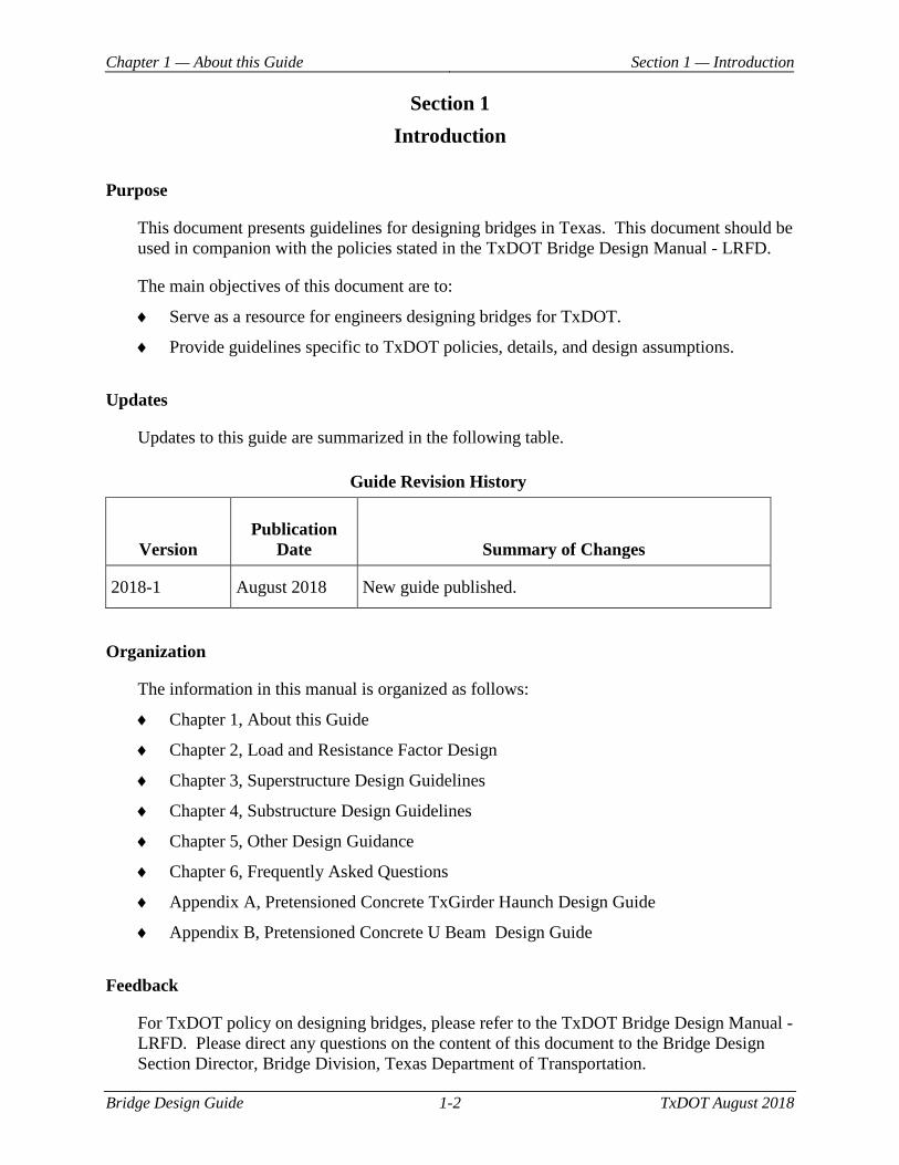
Updates to this guide are summarized in the following table.
Guide Revision History
Version Publication
Date Summary of Changes
2018-1 August 2018 New guide published.
Organization
The information in this manual is organized as follows:
♦ Chapter 1, About this Guide
♦ Chapter 2, Load and Resistance Factor Design
♦ Chapter 3, Superstructure Design Guidelines
♦ Chapter 4, Substructure Design Guidelines
♦ Chapter 5, Other Design Guidance
♦ Chapter 6, Frequently Asked Questions
♦ Appendix A, Pretensioned Concrete TxGirder Haunch Design Guide
♦ Appendix B, Pretensioned Concrete U Beam Design Guide
Feedback
For TxDOT policy on designing bridges, please refer to the TxDOT Bridge Design Manual - LRFD. Please direct any questions on the content of this document to the Bridge Design Section Director, Bridge Division, Texas Department of Transportation.
Bridge Design Guide 2-1 TxDOT August 2018
Chapter 2 Load and Resistance Factor Design
Contents: Section 1 — Load Factors .................................................................................................... 2-2
Chapter 2 — Load and Resistance Factor Design Section 1 — Load Factors
Bridge Design Guide 2-2 TxDOT August 2018
Section 1 Load Factors
Load and Resistance Factor Design
Load and Resistance Factor Design (LFRD) is a methodology that makes use of load factors and resistance factors based on the known variability of applied loads and material properties. Bracketed <references> reference relevant sections of the AASHTO LRFD Bridge Design Specifications.
Load Factors
• TxDOT recommends the following load factors from <Article 3.4.1>: The engineer may reduce the maximum load factor for wearing surfaces and utilities <DW in Table 3.4.1-2> to 1.25.

Bridge Design Guide 3-1 TxDOT August 2018
Chapter 3 Superstructure Design Guidelines
Contents: Section 1 — General Recommendations .............................................................................. 3-2
Section 2 — Superstructure Phasing Guidance .................................................................... 3-4
Section 3 — Corrosion Protection Measures ...................................................................... 3-10
Section 4 — Concrete Deck Slab on Stringers ................................................................... 3-11
Section 5 — Concrete Deck Slab on U Beams ................................................................... 3-13
Section 6 — Pretensioned Concrete I Girders .................................................................... 3-14
Section 7 — Pretensioned Concrete U Beams ................................................................... 3-16
Section 8 — Pretensioned Concrete Slab Beams and Decked Slab Beams ....................... 3-18
Section 9 — Pretensioned Concrete Box Beams ................................................................ 3-19
Section 10 — Straight and Curved Plate Girders ............................................................... 3-21
Section 11 — Spliced Precast Girders ................................................................................ 3-22
Chapter 3 — Superstructure Design Guidelines Section 1 — General Recommendations
Bridge Design Guide 3-2 TxDOT August 2018
Section 1 General Recommendations
Prestressed Concrete Beam and Girder Design
TxDOT’s policy is held firmly to a 6.0 ksi maximum allowable concrete strength (f’ci) at time of release of prestressing tension. The most severe Alkali Silica Reaction (ASR) and Delayed Ettringite Formation (DEF) problems in Texas have been in precast members. Texas has some of the most highly reactive aggregates in the country. For prestressed concrete, fabricators often use high cement contents to gain early strength, which means more alkalis. Large amounts of reactive silica plus large amounts of alkali equal higher ASR potential. The Class F fly ash typically used in our prestressed concrete helps mitigate these issues, but with the decreasing availability of fly ash and changing fly ash chemistry, ASR may still be an issue.
Incidents of ASR have caused TxDOT to revisit mix designs and the attainable concrete strengths used in the fabrication of prestressed concrete products. Item 421, Hydraulic Cement Concrete, requires fly ash or other combinations of supplementary cementing materials to be used in all beam production. This will result in slower strength gains which could have a negative impact on fabricator production and ultimately on girder costs. In order for fabricators to achieve higher early age concrete strengths with these slower strength gaining mixes, use of additional cement is often added.
The other issue that occurs in prestressed concrete is the use of low water-to-cementitious ratios (w/cm). Autogenous shrinkage and other problems related to the low w/cm ratios have increasingly become an issue in precast plants to the point that TxDOT put a limit on how low the fabricator can set the w/cm ratio. TxDOT has seen a large amount of early age cracking in prestressed girders that is now believed to be caused by high cement contents and very low w/cm ratios.
Specifying release strengths above the 6.0 ksi limit encourages the use of higher cement contents, which increases the likelihood of premature concrete deterioration. Low cement content has numerous benefits such as lower shrinkage and heat of hydration generation. Again, Texas is a unique case because essentially all our aggregate deposits are reactive. For this reason, these additional steps are necessary to ensure good long term durability and performance.
As stated in the policy manual, TxDOT Bridge Design Manual - LRFD, limit concrete strength at time of release of prestressing tension, f'ci, to a maximum of 6.0 ksi. Design concrete strength, f'c, is limited to a maximum of 8.50 ksi.
The following links are provided for additional reading on ASR:
♦ Preventing Alkali-Silica Reaction and Delayed Ettringite Formation in New Concrete http://ctr.utexas.edu/wp-content/uploads/pubs/0_4085_S.pdf

Chapter 3 — Superstructure Design Guidelines Section 1 — General Recommendations
Bridge Design Guide 3-3 TxDOT August 2018
♦ Guidelines for the Use of Lithium to Mitigate or Prevent Alkali-Silica Reaction (ASR) https://www.fhwa.dot.gov/publications/research/infrastructure/pavements/pccp/03047/index.cfm
Chapter 3 — Superstructure Design Guidelines Section 2 — Superstructure Phasing Guidance
Bridge Design Guide 3-4 TxDOT August 2018
Section 2 Superstructure Phasing Guidance
Phased Construction Recommendations
Do not use span standard detail sheets for phased structures. In other words, for a 38 ft. roadway phased bridge, do not use the 38 ft. roadway standards.
Geometric Constraints
When selecting a location for the phase line, consider the following items:
♦ Traffic needs and the placement of any temporary barriers. If the clear distance between the back of the barrier and the edge of the slab is less than 2 feet, pin the barrier to the deck. If possible, allow a 2 ft. buffer when placing the temporary barrier on new bridge deck to avoid the need for installing pins in the new bridge deck.
♦ When building next to an existing structure (such as for phased replacements), provide enough space between the existing structure and the new construction to accommodate splicing of the deck reinforcement, the portion of the beam that extends beyond the edge of slab, the portion of bent or abutment that extends past the beam edge, any reinforcing of the bent or abutment that extends into the next phase, and form work.
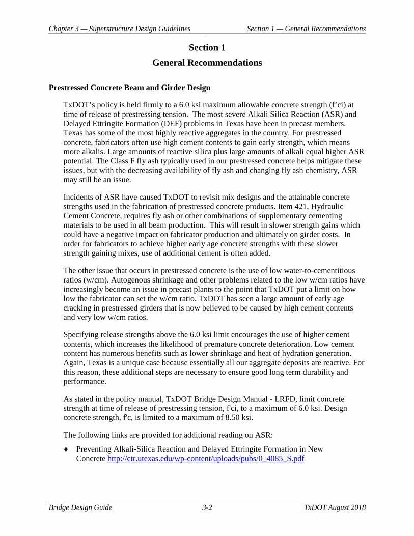
♦ For TxGirders, place the phase line as shown in Figure 3-1.
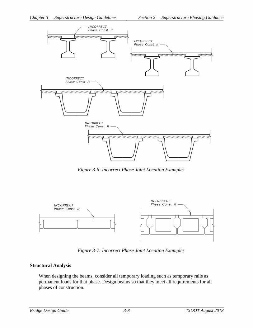
1. Do not place a phase line in the middle or at the edge of a precast panel as shown in Figure 3-6.
2. Do not place the phase line closer than 7 1/2 inches from the beam edge, to allow for the use of precast panels in the future phase.
3. Place the phase line a minimum of 4 inches past the centerline of the girder, so that the horizontal interface reinforcement is cast into the initial construction phase of the slab.
4. Alternately, consider placing the phase line between two beams. Treat the slab between the beam and the phase line as an overhang. Do not allow the use of panels in this space.
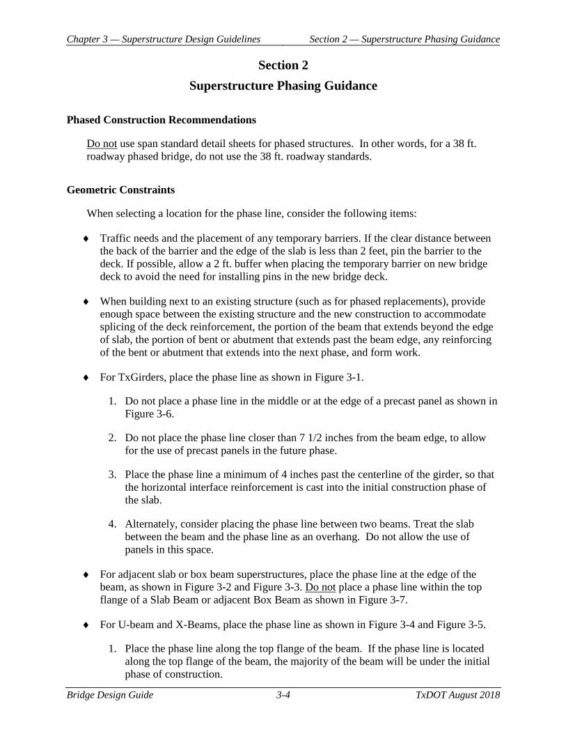
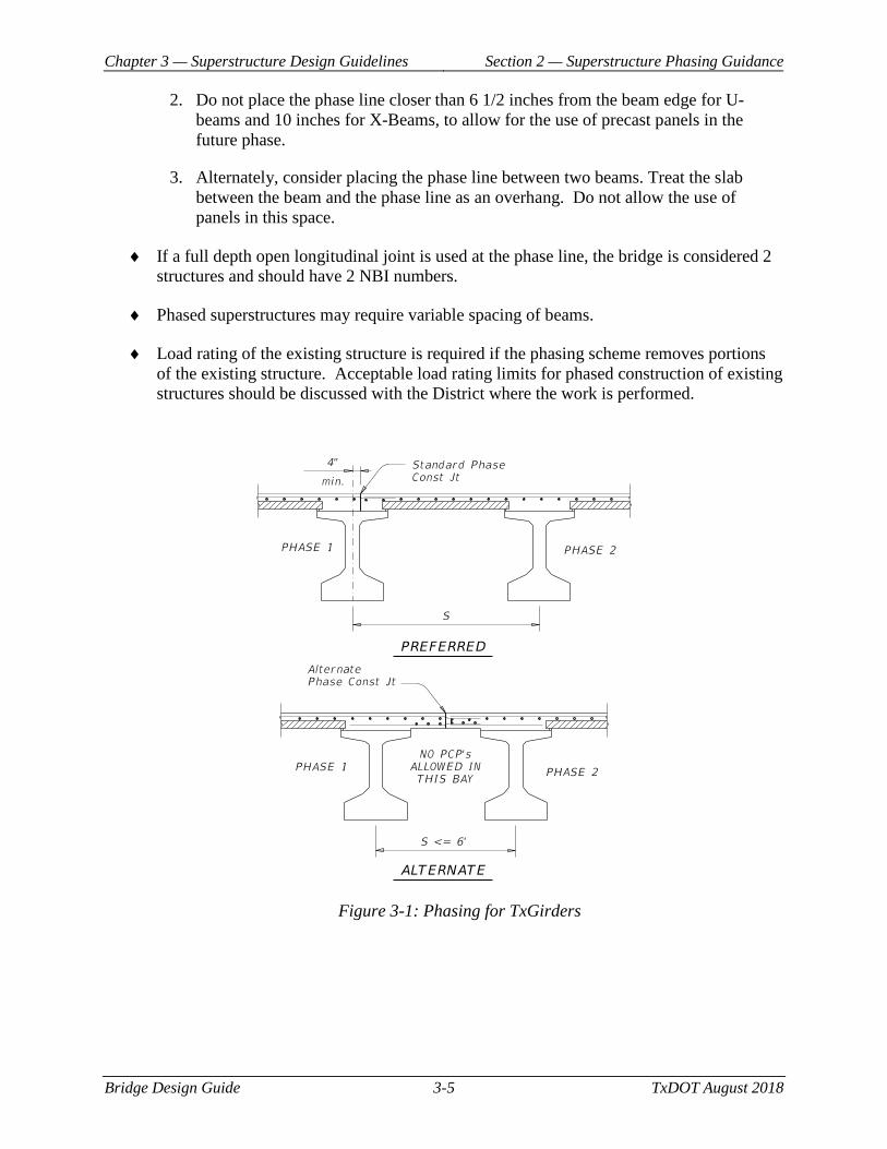
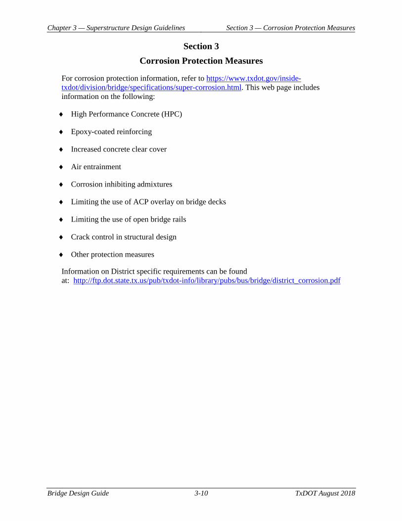
♦ For adjacent slab or box beam superstructures, place the phase line at the edge of the beam, as shown in Figure 3-2 and Figure 3-3. Do not place a phase line within the top flange of a Slab Beam or adjacent Box Beam as shown in Figure 3-7.
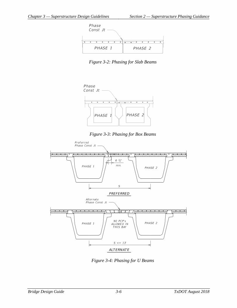
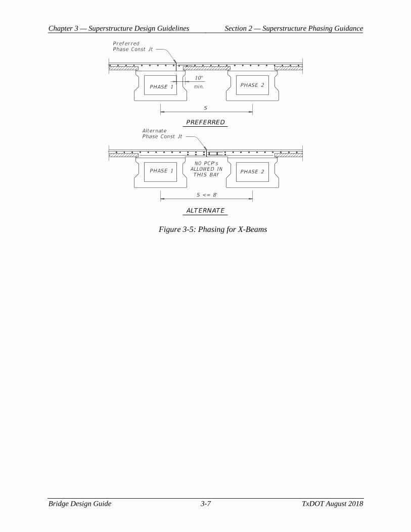
♦ For U-beam and X-Beams, place the phase line as shown in Figure 3-4 and Figure 3-5.
1. Place the phase line along the top flange of the beam. If the phase line is located along the top flange of the beam, the majority of the beam will be under the initial phase of construction.
Chapter 3 — Superstructure Design Guidelines Section 2 — Superstructure Phasing Guidance
Bridge Design Guide 3-5 TxDOT August 2018
2. Do not place the phase line closer than 6 1/2 inches from the beam edge for U-beams and 10 inches for X-Beams, to allow for the use of precast panels in the future phase.
3. Alternately, consider placing the phase line between two beams. Treat the slab between the beam and the phase line as an overhang. Do not allow the use of panels in this space.
♦ If a full depth open longitudinal joint is used at the phase line, the bridge is considered 2 structures and should have 2 NBI numbers.
♦ Phased superstructures may require variable spacing of beams.
♦ Load rating of the existing structure is required if the phasing scheme removes portions of the existing structure. Acceptable load rating limits for phased construction of existing structures should be discussed with the District where the work is performed.
Figure 3-1: Phasing for TxGirders
Chapter 3 — Superstructure Design Guidelines Section 2 — Superstructure Phasing Guidance
Bridge Design Guide 3-6 TxDOT August 2018
Figure 3-2: Phasing for Slab Beams
Figure 3-3: Phasing for Box Beams
Figure 3-4: Phasing for U Beams
Chapter 3 — Superstructure Design Guidelines Section 2 — Superstructure Phasing Guidance
Bridge Design Guide 3-7 TxDOT August 2018
Figure 3-5: Phasing for X-Beams
Chapter 3 — Superstructure Design Guidelines Section 2 — Superstructure Phasing Guidance
Bridge Design Guide 3-8 TxDOT August 2018
Figure 3-6: Incorrect Phase Joint Location Examples
Figure 3-7: Incorrect Phase Joint Location Examples
Structural Analysis
When designing the beams, consider all temporary loading such as temporary rails as permanent loads for that phase. Design beams so that they meet all requirements for all phases of construction.
Chapter 3 — Superstructure Design Guidelines Section 2 — Superstructure Phasing Guidance
Bridge Design Guide 3-9 TxDOT August 2018
The beam located under the phase line will have less dead load deflection than the other beams constructed at the same time. This beam will not deflect additionally when the remainder of the slab is cast, due to the added stiffness of the cured slab. When calculating haunch for the beam along the phase line, use the dead load deflection from the initial slab weight. Do not use the full dead load deflection due to the full slab weight (initial and final).
Consider lowering the bearing seat elevations of later phases to account for the potential for higher than predicted cambers. There is no way to adjust the roadway grade in subsequent phases to accommodate high camber girders.
Software
It is recommended to use PGSuper for beam design. Model phasing in PGSuper by using separate files for each phase and the completed structure. Refer to PGSuper Design Guide for further guidance about using PGSuper for beam design. Alternatively, use this spreadsheet to calculate live load distribution factors and manually input them into PGSuper. PGSuper can be downloaded from:
♦ Engineering Software http://www.txdot.gov/business/resources/engineering-software.html
Chapter 3 — Superstructure Design Guidelines Section 3 — Corrosion Protection Measures
Bridge Design Guide 3-10 TxDOT August 2018
Section 3 Corrosion Protection Measures
For corrosion protection information, refer to https://www.txdot.gov/inside-txdot/division/bridge/specifications/super-corrosion.html. This web page includes information on the following:
♦ High Performance Concrete (HPC)
♦ Epoxy-coated reinforcing
♦ Increased concrete clear cover
♦ Air entrainment
♦ Corrosion inhibiting admixtures
♦ Limiting the use of ACP overlay on bridge decks
♦ Limiting the use of open bridge rails
♦ Crack control in structural design
♦ Other protection measures
Information on District specific requirements can be found at: http://ftp.dot.state.tx.us/pub/txdot-info/library/pubs/bus/bridge/district_corrosion.pdf
Chapter 3 — Superstructure Design Guidelines Section 4 — Concrete Deck Slab on Stringers
Bridge Design Guide 3-11 TxDOT August 2018
Section 4 Concrete Deck Slab on Stringers
Geometric Constraints
Deck slabs less than 8.5 in. thick are not recommended with TxDOT's standard prestressed concrete panels because they are not as durable or as constructible and they do not provide enough practical room above a 4-in. panel. An 8.5 in. thick deck provides added durability and allows for grinding if the grade is off.
Structural Analysis
Refer to the TxDOT Bridge Design Manual – LRFD for information on Structural Analysis.
Design Criteria
TxDOT’s slabs on beams and girders is based on empirical deck design, also known as isotropic deck design. This decision was based on various research projects, collaboration with construction and maintenance experts, and past performance. For more information on TxDOT’s policy on empirical deck design refer to the TxDOT Bridge Design Manual – LRFD.
Software
No software is needed for the majority of deck slabs. For special cases, use RISA 3D or any suitable finite element program.
Detailing
♦ To account for reduced wheel load distribution at transverse slab edges, strengthen the slab by increasing its depth, as shown on the Thickened Slab End Details standard drawing.
♦ The standard deck slab corner break dimension is 2 ft. - 0 in when skew is more than 15 degrees. The corner break point must occur at least 1 in. and preferably 3 in. from the toe of any concrete parapet into which an expansion joint is upturned.
♦ With simple-span construction, minimize expansion joints by creating multi-span units with the slab continuous over interior bents. At bents without expansion joints, locate a control joint or construction joint in the deck. However, if a short span is placed at the end of multi-span unit, verify that slipping of the bearing pads will not occur (Refer to bearing design section). Also, the engineer should verify that the standard bearings do not exceed their design limits when units are comprised of more than 3 spans.
Chapter 3 — Superstructure Design Guidelines Section 4 — Concrete Deck Slab on Stringers
Bridge Design Guide 3-12 TxDOT August 2018
♦ Additional longitudinal reinforcing steel is required for continuous steel girders <Article 6.10.1.7>. Adding one #5 bar in the top slab between each usual longitudinal bar meets this requirement.
Chapter 3 — Superstructure Design Guidelines Section 5 — Concrete Deck Slab on U Beams
Bridge Design Guide 3-13 TxDOT August 2018
Section 5 Concrete Deck Slab on U Beams
Materials
See Corrosion Protection Measures in Section 3 for special considerations.
Structural Analysis
Consider using a normal overhang when conditions make the sloped overhang unsightly or difficult and expensive to construct. For the sloped overhang, the slope of the bottom face of the overhang may vary significantly when used with curved slab edges primarily because of the overhang distance varying along the length of the exterior U beam.
On a straight bridge slab edge, however, the slope of the bottom face of the overhang varies only because of the vertical curvature of the roadway surface and the camber and dead load deflection of the exterior U beam, thereby creating a more pleasing appearance.
Detailing
Use slab dowels to provide lateral restraint when constructing U beams with inverted-tee bents. Refer to the UBMS standard for location and placement. A left and right bearing seat elevation is given for each U-beam bearing seat location. Bearing seats for U beams are level perpendicular to the centerline of the bent but slope uniformly between the left and right bearing seat elevations. This allows the bearing pads to taper in one direction.
Chapter 3 — Superstructure Design Guidelines Section 6 — Pretensioned Concrete I Girders
Bridge Design Guide 3-14 TxDOT August 2018
Section 6 Pretensioned Concrete I Girders
Materials
For concrete strengths, see the TxDOT Bridge Design Manual - LRFD.
Structural Analysis
Do not increase section properties of the girder to account for the transformed area of strands or mild steel.
Design Criteria
For grade separation structures, use the same girder depth for the full length of structure for economies of scale and aesthetic reasons. Stream crossing structures may have different types and sizes of girders for purposes of economy. Optimize girder spacing in each span. Maintaining constant girder spacing for the full length of structure is not necessary. Selection of the proper type of girder for a span is a matter of economics; calculate relative costs using current average bid prices for girders and slab.
Use relative humidity of 60% regardless of the location of the bridge. The reason for this is that 60% is about an average relative humidity for Texas and is consistent with designs shown on standard drawings. In addition, the beams could be cast at a location with a different humidity than the bridge location.
For bridges with multiple spans, it is more economical to group beam designs. This allows the fabricator to limit the number of different types of beams to fabricate. Beams should also be grouped across various bridges in the same project. For grouping beams, TxDOT recommends grouping beams where there is a difference of 4 strands or less. Provide a unique beam design where there is a difference of 6 strands or more.
There are physical limits on the total prestress force a fabricator’s production lines can handle and too many strands can overwhelm the mild reinforcement meant to control bursting and spalling cracks in the girder end regions. The software might indicate a design works, but the design can very well be impractical or impossible to construct. For TX and I girders, restrict the number of strands in girders as follows:
♦ TX28 thru TX40, 44 – 0.6” strands
♦ TX46 thru TX70, 54 – 0.6” strands
When framing a flared span, to avoid fabricating several different geometrically precast deck panels, consider flaring as few beams as necessary.
Chapter 3 — Superstructure Design Guidelines Section 6 — Pretensioned Concrete I Girders
Bridge Design Guide 3-15 TxDOT August 2018
Software
It is recommended to use PGSuper for beam design. Refer to PGSuper Design Guide for further guidance about using PGSuper for beam design. PGSuper calculated live load distribution factors. Alternatively, use this spreadsheet to calculate live load distribution factors and manually input them into PGSuper. PGSuper can be downloaded from:
♦ Engineering Software http://www.txdot.gov/business/resources/engineering-software.html
Detailing
For each design, show optional design parameters for maximum top flange stress, bottom flange stress, and ultimate moment due to all design loads on the plans. The fabricator has the option to use other strand arrangements if design parameters are satisfied by the prestress and concrete strength selected.
Chapter 3 — Superstructure Design Guidelines Section 7 — Pretensioned Concrete U Beams
Bridge Design Guide 3-16 TxDOT August 2018
Section 7 Pretensioned Concrete U Beams
Materials
For concrete strengths, see the TxDOT Bridge Design Manual.
Geometric Constraints
♦ U beams are not vertical but are rotated to accommodate the average cross slope of a given span. As a result, the depth of slab haunch at the left and right top edges of the beam may differ. Pay special attention to these beams in calculating the haunch values.
♦ Left and right bearing seat elevations are located at the intersection of the edges of bearing seats with centerline bearings. When calculating these elevations for each beam seat, be careful to apply the appropriate deduction at that elevation point - that is, the minimum deduction at the correct elevation point and the maximum deduction at the other elevation point. Typically, the minimum deduction and maximum deduction are each applied at diagonally opposite corners of a beam in plan view. See Appendix B, Prestressed Concrete U Beam Design Guide, for information on calculating U-beam slab haunches. The information is tailored for use with BGS, but the principles behind the method remain the same.
♦ One method for framing U-beam centerlines is at the top of the beam. This prevents spacing at the top of the beam from varying due to the cross slope of the beam and, thus, simplifies slab formwork dimensions for construction.
♦ The alternate method for framing U-beam centerlines is at the bottom of the beam. This method allows the U beams to be framed as vertical members whereby the beam spacings dimensioned on the span details and beam layouts match the beam spacings shown on the substructure details. However, if this method is used, call attention to the variable beam spacing at the top of the beam in the plans. A construction note is recommended on the span details stating, "Beam spacing shown is measured at bottom of beam. Beam spacing at top of beam may vary due to cross slope of U beams."
♦ TxDOT's Bridge Division currently uses the Bridge Geometry System (BGS) software program to frame U beams. The latest version of BGS frames U beams using the alternate method. The BGS manual includes information on three framing options written specifically for U beams: Options 20, 21, and 22. These framing options help the designer calculate accurate slab haunch values, bearing seat elevations, and bearing pad taper reports for U beams under the alternate method.
♦ Use the same minimum haunch value for all U beams in a given span if reasonable to do so.
♦ Provide at least 3 in. from the end of the cap or corbel to the edge of the bearing seat.

Chapter 3 — Superstructure Design Guidelines Section 7 — Pretensioned Concrete U Beams
Bridge Design Guide 3-17 TxDOT August 2018
Software
It is recommended to use PGSuper for beam design. Refer to PGSuper Design Guide for further guidance about using PGSuper for beam design. PGSuper calculated live load distribution factors. Alternatively, use this spreadsheet to calculate live load distribution factors and manually input them into PGSuper. PGSuper can be downloaded from:
♦ Engineering Software http://www.txdot.gov/business/resources/engineering-software.html
Detailing
♦ Detail span sheets for a cast-in-place slab with prestressed concrete panels. A full-depth cast-in-place deck with permanent metal deck forms may be provided at the contractor's option.
♦ Use thickened slab ends at all expansion joints with non-inverted tee bents. See the Miscellaneous Slab Details standard drawing for details of thickened slab ends.
♦ Do not show a detailed bill of reinforcing steel on production drawings. Instead, show a table of bar designations with sizes used in the slab as is currently done with TxGirder structures.
♦ If inverted-tee caps are used and are sloped to match the sloping face of the U beam, use a 4:1 slope normal to the centerline of the bent.
♦ Use slab dowels to provide lateral restraint when constructing U beams with inverted-tee bents. These dowels are located at the top of the inverted-tee stem and are in a slotted pipe to allow for expansion and contraction of the unit. Typically, only one dowel is placed at the centerline of every beam 1 ft. from the centerline of the bent. Slab dowels need to be placed on only one side of the centerline of the bent. A left and right bearing seat elevation is given for each U-beam bearing seat location. Bearing seats for U beams are level perpendicular to the centerline of the bent but slope uniformly between the left and right bearing seat elevations. This allows the bearing pads to taper in one direction.
♦ Include a Bearing Pad Taper Report sheet in the plans summarizing bearing pad tapers to be used by the fabricator. See Appendix B, Prestressed Concrete U-Beam Design Guide, for information on the calculation of bearing pad tapers for U beams.
Chapter 3 — Superstructure Design Guidelines Section 8 — Pretensioned Concrete Slab Beams and
Decked Slab Beams
Bridge Design Guide 3-18 TxDOT August 2018
Section 8 Pretensioned Concrete Slab Beams and Decked Slab Beams
Materials
For concrete strengths, see the TxDOT Bridge Design Manual.
Geometric Constraints
♦ Limit skew to 30 degrees. Larger skews may result in beam twist and uneven bearing on the pads.
♦ The requirement to bevel the bearing pads to match the beam slope on the Elastomeric Bearing Details sheet will not result in parallel pad and beam surfaces for skewed bridges. The actual calculations and fabrication of pads for each particular skewed case is complex. Given the small area of the pads, experience with box beams and the nearly parallel surfaces, the pads should be able to deform sufficiently to accommodate the mismatches.
♦ When both a vertical curve and skew exist, a complex planar relationship develops between the skewed bottom of the slab beam, bearing pad, and bent or abutment cap: a stepped bearing seat arrangement on the caps may be required.
♦ Except for the T411 and C411 railings, no adjustment is needed to individual reinforcing bars embedded into the decked slab beam to account for the effects of vertical curve. Theoretically, each embedded bar should protrude from the beam a different amount. However, in the most extreme case (VC length = 600 ft., tangent slopes = -5%, 5%, and span length = 50 ft.), the maximum variation of the profile grade line from a straight line drawn between top of slab at adjacent bents is only 5/8 in. This is not significant enough to warrant complicating the detailing, fabrication, and installation of the railing reinforcing.
Software
It is recommended to use PGSuper for beam design. Refer to PGSuper Design Guide for further guidance about using PGSuper for beam design. PGSuper calculated live load distribution factors. Alternatively, use this spreadsheet to calculate live load distribution factors and manually input them into PGSuper. PGSuper can be downloaded from:
♦ Engineering Software http://www.txdot.gov/business/resources/engineering-software.html
Chapter 3 — Superstructure Design Guidelines Section 9 — Pretensioned Concrete Box Beams
Bridge Design Guide 3-19 TxDOT August 2018
Section 9 Pretensioned Concrete Box Beams
Materials
For recommended concrete strengths, see the TxDOT Bridge Design Manual.
Geometric Constraints
♦ A three-pad system is currently used with box beams. Typically, the forward station end of the beam sits on a single elastomeric bearing pad while the back station end sits on two smaller pads.
♦ Box beams are fabricated using a two-stage monolithic casting. The bottom slab is cast in the first stage, and the sides and top are cast in the second stage while the slab concrete is still plastic. In addition, cardboard void forms are no longer permitted. All interior voids must be formed with polystyrene. Void drain holes are installed at the corners of the bottom slab during fabrication.
Design Criteria:
♦ Use a cast-in-place reinforced concrete slab rather than an ACP overlay on box beam bridges. The slab should have a 5-in. minimum thickness, typically at the center of the span (or at center of bearing in situations such as crest vertical curves).
♦ Avoid slab overhangs. Choose box beams and gap sizes so that the edge of the slab corresponds to the edge of the top flange of the exterior beams.
♦ Box beams are not appropriate for use on curved structures and should be avoided on flared structures. The complexity of the geometry required to frame the bridge increases dramatically as the degree of curvature exceeds 1 or 2 degrees.
♦ Use 5-ft. boxes as exterior beams when the roadway width requires a combination of both 4-ft. and 5-ft. boxes.
♦ Do not use dowels for lateral restraint. Provide lateral restraint by 12-in.wide by 7-in. tall ear walls located at the ends of each abutment and interior bent cap. Provide a 1/2-in. gap between the ear wall and the outside edge of the exterior beam.
♦ Bearing seats are not used with box beams. The pads sit directly on top of the cap. Provide top-of-cap elevations at the points coinciding with the outer edge of the exterior boxes at the centerline of bearing. Also provide elevations at any intermediate points along the cap, at the centerline of bearing, where either a change in cap slope or change in cap elevation occurs.
Chapter 3 — Superstructure Design Guidelines Section 9 — Pretensioned Concrete Box Beams
Bridge Design Guide 3-20 TxDOT August 2018
♦ Box beams are not vertical but either parallel the roadway surface when the cross slope is constant or are rotated to the average cross slope of a span in a transition area. Because there are no bearing seat build-ups, the top of the cap must be sloped to match the rotation of the beams.
♦ Provide a minimum of three elevation points for unskewed spans with an even number of box beams and a constant housetop profile: one at the outside edge of each of the exterior beams and a third point at the center of the middle joint. Provide four elevation points for spans with an odd number of beams: one at the outside edge of each exterior beam and one at the center of each joint on either side of the middle beam.
♦ Framing is complicated in cross-slope transition areas and skewed bridges. Orient the beams to minimize the variation in slab thickness both longitudinally and transversely along the span. This may require stepping the cap at some joints so that adjacent beams not only have a different slope but also sit at a different elevation. Elevation points may be required as often as every joint in some situations. The forward half of an interior bent cap may have a different elevation than the back half at some locations.
Software
It is recommended to use PGSuper for beam design. Refer to PGSuper Design Guide for further guidance about using PGSuper for beam design. PGSuper calculated live load distribution factors. Alternatively, use this spreadsheet to calculate live load distribution factors and manually input them into PGSuper. PGSuper can be downloaded from:
♦ Engineering Software http://www.txdot.gov/business/resources/engineering-software.html
Chapter 3 — Superstructure Design Guidelines Section 10 — Straight and Curved Plate Girders
Bridge Design Guide 3-21 TxDOT August 2018
Section 10 Straight and Curved Plate Girders
Materials
For recommended steel strengths, see the TxDOT Bridge Design Manual - LRFD.
Resources
TxDOT Preferred Practices for Steel Bridge Design, Construction, and Fabrication, TxDOT 2015 G12.1-2016 Guidelines to Design for Constructability, American Association of Highway Officials (AASHTO) and National Steel Bridge Alliance (NSBA)

Chapter 3 — Superstructure Design Guidelines Section 11 — Spliced Precast Girders
Bridge Design Guide 3-22 TxDOT August 2018
Section 11 Spliced Precast Girders
Structural Analysis
♦ Bridge Division suggests using the section properties given on the TxDOT website: • I-Section: http://ftp.dot.state.tx.us/pub/txdot-info/brg/long-span-i-girders.pdf • U-Section: http://ftp.dot.state.tx.us/pub/txdot-info/brg/long-span-u-
girders.pdf Web width of these sections may be varied to optimize the sections in meeting design requirements.
♦ The preferred thickness of the web or flange is 9 inches.
Bridge Design Guide 4-1 TxDOT August 2018
Chapter 4 Substructure Design Guidelines
Contents: Section 1 — Overview .......................................................................................................... 4-2
Section 2 — General Recommendations .............................................................................. 4-3
Section 3 — Abutments ........................................................................................................ 4-4
Section 4 — Rectangular Reinforced Concrete Caps ........................................................... 4-5
Section 5 — Inverted Tee Reinforced Concrete Caps .......................................................... 4-8
Section 6 — Substructure Phasing Guidance ..................................................................... 4-10
Section 7 — Lateral Restraint for Bridge Superstructures ................................................. 4-12
Section 8 — Columns for Multi-Column Bents ................................................................. 4-14
Section 9 — Columns for Single Column Bents ................................................................ 4-16
Section 10 — Design Resources ......................................................................................... 4-17
Chapter 4 — Substructure Design Guidelines Section 1 — Overview
Bridge Design Guide 4-2 TxDOT August 2018
Section 1 Overview
This section provides guidance and recommendations on Load and Resistance Factor Design (LRFD) of specific bridge substructure components.

Chapter 4 — Substructure Design Guidelines Section 2 — General Recommendations
Bridge Design Guide 4-3 TxDOT August 2018
Section 2 General Recommendations
Limit States
TxDOT recommends the following limit states for design of bridge system components <Article 3.4.1>:
Component Limit State
Concrete Bent Caps Strength I, Service I, and Service I with Dead Load only
Columns Strength I, III, and V, Service I and IV, and Extreme II (for vehicle or vessel collision, when required)
Corrosion Protection Measures
Refer to Chapter 3 for information on corrosion protection measures.
Chapter 4 — Substructure Design Guidelines Section 3 — Abutments
Bridge Design Guide 4-4 TxDOT August 2018
Section 3 Abutments
Detailing
Consider using a construction joint in abutment caps when the length of cap exceeds 80 ± ft. Evaluation should be made on a per project basis. Locate the joint close to a dead load inflection point. The joint should clear the bearing seat areas.
Place dowels D at outside Tx girders and X beams only. Phased construction may require additional dowels, and wide structures may require dowels to be moved to inside girders. When the distance between the centerlines of the outside girders exceeds 80 feet, move the dowels to an inside girder. Keep the distance between the dowels a maximum of 80 feet (+/-) apart. Use dowels D at abutments for single span Tx girder and X beam bridges, however do not use them at the ends of multi-span Tx girder and X beam units.
Structural Analysis
♦ Refer to Section 4 for information on the structural analysis.
Chapter 4 — Substructure Design Guidelines Section 4 — Rectangular Reinforced Concrete Caps
Bridge Design Guide 4-5 TxDOT August 2018
Section 4 Rectangular Reinforced Concrete Caps
Geometric Constraints
Cap width should be 3 in. wider than the supporting columns to allow column reinforcing to extend into the cap without bending.
Structural Analysis
♦ Apply dead load reactions due to slab and beam weight as point loads at centerline of beam. For all beams, except U Beams, distribute the weight of one railing, sidewalks, and/or medians to no more than three beams, applied to the composite cross section. For U Beams, distribute 2/3 the weight of one railing, sidewalks, and/or medians to a single U Beam and 1/3 to the adjacent beam, applied to the composite cross section. Considerations should be given to wide medians and sidewalks, where the weight may be distributed to more than the prescribed amount of beams. Distribute dead loads due to overlay evenly to all beams.
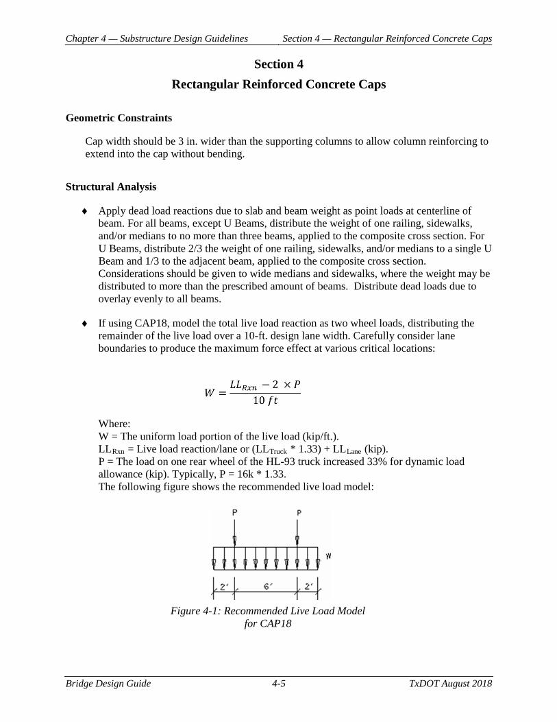
♦ If using CAP18, model the total live load reaction as two wheel loads, distributing the remainder of the live load over a 10-ft. design lane width. Carefully consider lane boundaries to produce the maximum force effect at various critical locations:
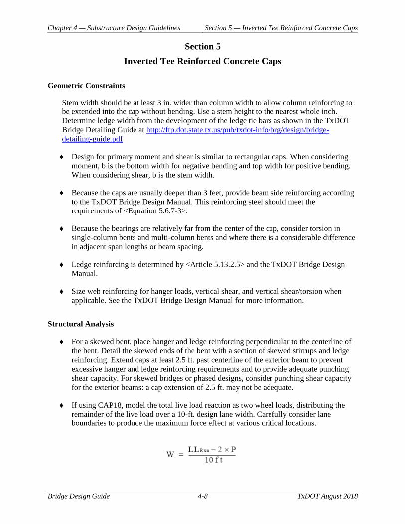
Where: W = The uniform load portion of the live load (kip/ft.). LLRxn = Live load reaction/lane or (LLTruck * 1.33) + LLLane (kip). P = The load on one rear wheel of the HL-93 truck increased 33% for dynamic load allowance (kip). Typically, P = 16k * 1.33. The following figure shows the recommended live load model:
Figure 4-1: Recommended Live Load Model for CAP18
Chapter 4 — Substructure Design Guidelines Section 4 — Rectangular Reinforced Concrete Caps
Bridge Design Guide 4-6 TxDOT August 2018
Design Criteria
Bridge Division encourages the engineer to use Article 5.7.3.4.2 General Procedure for shear design. Bridge Division discourages the use of Article 5.7.3.4.1 Simplified Procedure for Nonprestressed Sections, as it results in a significantly overly conservative shear design. However, if the engineer selects to use the Simplified Procedure, the engineer must ensure that the minimum stirrup spacing requirements are not violated. If the required stirrup spacing is less than the minimum allowed per AASHTO, re-evaluate using Article 5.7.3.4.2 General Procedure, instead of increasing the dimensions of the cross section in an attempt to force the Simplified Procedure to be sufficient.
Detailing
♦ Consider using a construction joint in multicolumn bents when the distance between outside columns exceeds 80 ± ft. Evaluation should be made on a per project basis. Locate the joint close to a dead-load inflection point but not under a bearing seat buildup.
♦ Typically the minimum number of bars is four top and bottom, and the maximum number in a layer is limited by a 3-in. clear-spacing requirement to facilitate concrete placement and vibration. A second layer may be placed 4 in. on center from the outside layer. A third layer should be used only in very deep caps. A horizontal tie bar tied to the vertical stirrup legs should support second and third layers. In heavily reinforced caps, bundling bars in two-bar bundles may be used to maintain necessary clear spacing. Layered and bundling bars should comply with AASHTO Chapter 5.
♦ Bars longer than 60 ft. require laps. Try to locate these laps in compression or very low tension zones. Base lap lengths on tension lap requirements (see the Bridge Detailing Guide). Consider staggering or alternating laps in adjacent bars to minimize congestion. Mechanical couplers or welded splices may be specified for phased construction.
♦ Many cantilevers are too short to allow full development length for the #11 Grade 60 top reinforcement. However, for TxGirder superstructures, the reaction from the outside beam provides a clamping effect and a bar extension of 15 in. beyond the center of the beam will develop the bar.
♦ For most conventional caps, use #5 stirrups with a 4-in. minimum and 12-in. maximum spacing. Double stirrups may be required close to column faces. For large heavily reinforced caps, use #6 stirrups.
♦ Pay attention to the bearing seat build-up for prestressed beam spans. Extreme grades and skews can produce conflicts between the bearing seat or bent cap and the beams or bearings of adjacent spans if the seats are not shown properly on the bent details. The Bridge Detailing Guide shows typical bearing seat configurations. Bearing seat build-ups taller than 3 in. require reinforcement, which should be shown on the detail.
Chapter 4 — Substructure Design Guidelines Section 4 — Rectangular Reinforced Concrete Caps
Bridge Design Guide 4-7 TxDOT August 2018
♦ Place dowels D at outside Tx girders and X beams only. Phased construction may require additional dowels, and wide structures may require dowels to be moved to inside girders. When the distance between the centerlines of the outside girders exceeds 80 feet, move the dowels to an inside girder. Keep the distance between the dowels a maximum of 80 feet (+/-) apart. Use Dowels D at the ends of Tx girder and X beams single spans, but do not use them at the ends of units.
Chapter 4 — Substructure Design Guidelines Section 5 — Inverted Tee Reinforced Concrete Caps
Bridge Design Guide 4-8 TxDOT August 2018
Section 5 Inverted Tee Reinforced Concrete Caps
Geometric Constraints
Stem width should be at least 3 in. wider than column width to allow column reinforcing to be extended into the cap without bending. Use a stem height to the nearest whole inch. Determine ledge width from the development of the ledge tie bars as shown in the TxDOT Bridge Detailing Guide at http://ftp.dot.state.tx.us/pub/txdot-info/brg/design/bridge-detailing-guide.pdf
♦ Design for primary moment and shear is similar to rectangular caps. When considering moment, b is the bottom width for negative bending and top width for positive bending. When considering shear, b is the stem width.
♦ Because the caps are usually deeper than 3 feet, provide beam side reinforcing according to the TxDOT Bridge Design Manual. This reinforcing steel should meet the requirements of <Equation 5.6.7-3>.
♦ Because the bearings are relatively far from the center of the cap, consider torsion in single-column bents and multi-column bents and where there is a considerable difference in adjacent span lengths or beam spacing.
♦ Ledge reinforcing is determined by <Article 5.13.2.5> and the TxDOT Bridge Design Manual.
♦ Size web reinforcing for hanger loads, vertical shear, and vertical shear/torsion when applicable. See the TxDOT Bridge Design Manual for more information.
Structural Analysis
♦ For a skewed bent, place hanger and ledge reinforcing perpendicular to the centerline of the bent. Detail the skewed ends of the bent with a section of skewed stirrups and ledge reinforcing. Extend caps at least 2.5 ft. past centerline of the exterior beam to prevent excessive hanger and ledge reinforcing requirements and to provide adequate punching shear capacity. For skewed bridges or phased designs, consider punching shear capacity for the exterior beams: a cap extension of 2.5 ft. may not be adequate.
♦ If using CAP18, model the total live load reaction as two wheel loads, distributing the remainder of the live load over a 10-ft. design lane width. Carefully consider lane boundaries to produce the maximum force effect at various critical locations.
Chapter 4 — Substructure Design Guidelines Section 5 — Inverted Tee Reinforced Concrete Caps
Bridge Design Guide 4-9 TxDOT August 2018
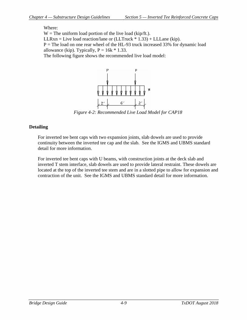
Where: W = The uniform load portion of the live load (kip/ft.). LLRxn = Live load reaction/lane or (LLTruck * 1.33) + LLLane (kip). P = The load on one rear wheel of the HL-93 truck increased 33% for dynamic load allowance (kip). Typically, P = 16k * 1.33. The following figure shows the recommended live load model:
Figure 4-2: Recommended Live Load Model for CAP18
Detailing
For inverted tee bent caps with two expansion joints, slab dowels are used to provide continuity between the inverted tee cap and the slab. See the IGMS and UBMS standard detail for more information.
For inverted tee bent caps with U beams, with construction joints at the deck slab and inverted T stem interface, slab dowels are used to provide lateral restraint. These dowels are located at the top of the inverted tee stem and are in a slotted pipe to allow for expansion and contraction of the unit. See the IGMS and UBMS standard detail for more information.
Chapter 4 — Substructure Design Guidelines Section 6 — Substructure Phasing Guidance
Bridge Design Guide 4-10 TxDOT August 2018
Section 6 Substructure Phasing Guidance
Phased Construction Recommendations
Do not use standard abutment, bent, or trestle detail sheets for phased structures.
Geometric Constraints
In most cases, the phase line in an abutment or interior bent will be offset from the phase line for the slab. The phase line should not be under a beam or within a bearing seat. Extend the abutment or interior bent past the slab phase line in order to provide support for the beam or girder. Preferably, the phase line should be a minimum of 4 inches from the bearing seat or edge of beam, whichever is greater.
When phasing an abutment or an interior bent, consider providing enough space between the existing structure and the new construction to accommodate splicing of the reinforcement and formwork. Consider how the next phase of construction will be impacted by the placement of phase lines and reinforcement that extends beyond the phase line. Drilled shaft for the next phase may lie within the length necessary for splicing. Avoid having splices that overlap drilled shaft locations in order to facilitate construction.
If unable to provide enough room to splice the reinforcement through traditional overlapping, use welded splices or mechanical couplers. In some cases, a combination of couplers/welded splices and traditional overlapping may be utilized for elements with varying bar sizes. Extend reinforcement that will be spliced by welds or mechanical couplers beyond the end of the cap by at least 1-foot.
As an alternative to splicing or welding the reinforcement, a full depth joint may be used at the phase line. For abutments, if a full depth joint is used, limit the space between abutments to 1-inch. Use bituminous fiber to fill the gap between the phases. Use a PVC waterstop across the space along the full height of the cap and backwall.
For bent caps, the full depth open joint at the phase line should be at least 1-foot wide to allow for forming of the adjacent phases. Individual bent caps would support each phase.
When selecting column or drilled shaft/pile spacing, try to keep the distance from face of column or drilled shaft/pile to the phase line between 0.5 and 4 feet. Overhangs greater than 4 feet can result in high negative moments and permanent deflection of the overhang under loading. The construction of additional phases will not remove this deflection.
Phased construction of abutments or bents may require that columns or drilled shafts be spaced at irregular intervals.
Chapter 4 — Substructure Design Guidelines Section 6 — Substructure Phasing Guidance
Bridge Design Guide 4-11 TxDOT August 2018
Offset old bent lines and new bents by at least 5 feet, if possible, to keep from fouling foundations on the existing structure. Pay attention when battered piling is shown on either existing or new construction. Also, investigate potential battered pile conflicts with wingwall foundations when abutments are heavily skewed.
Structural Analysis
When designing bents and abutments to be continuous after phasing, consider all stages of construction (including temporary loads) and the final configuration. Select flexural and shear reinforcement so that loading in all phases can be supported.
Design bents and abutments that have full depth joints at the phase line as individual components.
Detailing
Phased construction may require additional dowels, and wide structures may require dowels to be moved to inside girders. See the guidelines for abutments, interior bents, and inverted tees for maximum recommended space between dowels. If a full depth joint is used between the phases, each component may require a dowel.
Chapter 4 — Substructure Design Guidelines Section 7 — Lateral Restraint for Bridge
Superstructures
Bridge Design Guide 4-12 TxDOT August 2018
Section 7 Lateral Restraint for Bridge Superstructures
General
Lateral movement of superstructures can occur on water crossings due to flooding events and on grade separations due to cross slope with certain beam types. Provide effective lateral restraint in the form of shear keys as described in the TxDOT Bridge Design Manual – LRFD.
Bridges Crossing Water Features
The design criteria for bridges over water crossings provide an economical way to prevent the beams from separating from the substructure during a major storm or flood event.
I-Girder Bridges
Refer to the TxDOT Bridge Design Manual and Bridge Standard Shear Key Details for I-Girders (IGSK) for design and detailing information.
U-Beam Bridges
Crossing Water Features:
Refer to the TxDOT Bridge Design Manual and Appendix B of this Guide for more information.
Grade Separations:
Shear keys are required on bent caps when the roadway has a single direction cross-slope because U-beams are placed in a rotated position to match the roadway cross-slope; as such, the center of gravity of the beam is not coincident with the center of the bearing pad, and the beam has the potential to slide downhill with resistance provided by the shear resistance of the elastomeric pads. When the roadway cross-slope is crowned, beams on opposite sides of the crown will provide opposing forces, thus limiting lateral movement of the superstructure. When the roadway cross-slope is single-direction, the superstructure is not self-restrained and shear keys are needed to limit lateral movement.
Spread Slab Beam and Spread Box Beam (X-beam) Bridges
Grade Separations:
Chapter 4 — Substructure Design Guidelines Section 7 — Lateral Restraint for Bridge
Superstructures
Bridge Design Guide 4-13 TxDOT August 2018
Shear keys are required on bent and abutment caps of X-beams because X-beams are placed in rotated position to match the roadway cross-slope; as such, the center of gravity of the beam is not coincident with the center of the bearing pad, and the beam will slide downhill. When the roadway cross-slope is crowned, beams on opposite sides of the crown will provide opposing forces, thus limiting lateral movement of the superstructure. When the roadway cross-slope is single-direction, the superstructure is not self-restrained and shear keys are needed to limit lateral movement.
Crossing Water Features:
Refer to the TxDOT Bridge Standard Shear Key Details for X-Beams (XBSK) for design and detailing information. Contact TxDOT Bridge Division for guidance on shear key details for spread slab beam bridges, since currently there is not a standard detail.
Slab Beam, Box Beam, Decked Slab Beam, and Double-Tee Beam Bridges
Additional measures of lateral restraint are not required for slab beam, box beam, decked slab beam, and double-tee beam structures because the earwalls on the abutments and bents are considered to be adequate for preventing transverse movement.
Steel Beam or Girder Bridges
Crossing Water Features:
For additional considerations and guidance, refer to the TxDOT Preferred Practices for Steel Bridge Design, Fabrication, and Erection at http://ftp.dot.state.tx.us/pub/txdot-info/library/pubs/bus/bridge/steel_bridge.pdf
Chapter 4 — Substructure Design Guidelines Section 8 — Columns for Multi-Column Bents
Bridge Design Guide 4-14 TxDOT August 2018
Section 8 Columns for Multi-Column Bents
Structural Analysis
For typical bridges only:
♦ For analysis, the designer should consider predicted scour when determining column heights.
♦ Moments can be magnified to account for slenderness (P-delta) effects by using <Article 5.6.4.3> or other analytical methods. However, results are highly conservative.
♦ Analyze slender columns by taking effective length factors as 1.0 transversely and 1.5 longitudinally or by investigating secondary effects and biaxial bending.
♦ For multi-tier bents with square or round columns separated by tie beams, analyze as a frame, and magnify transverse and longitudinal moments separately.
♦ Column size may change within the bent height, producing a multi-tiered bent. Consider multi-columns bent tiers with web walls to be braced in the transverse direction. Column capacity in the longitudinal direction is not affected by the web wall.
♦ Design and model single-tier bent columns without a tie beam or web wall as individual columns with bottom conditions fixed against rotation and deflection in the transverse direction but free to rotate and deflect in the longitudinal direction. Top-of-column conditions should be considered free to translate but not rotate in the transverse direction.
♦ In most cases, it can be assumed when determining fixity conditions for loads, other than temperature and shrinkage, that columns on single drilled shafts are fixed at three shaft diameters but not more than 10 ft. below the top of the shaft. This should always be reviewed by a Geotechnical Engineer to evaluate and determine the fixity condition.
♦ Refine designs by limiting longitudinal deflections to the maximum movement allowed due to joint closure.
Guidance
For typical bridges only:
♦ Round columns are preferred for multicolumn bents with rectangular caps and are used for most structures. See the TxDOT Bridge Detailing Guide for available column size, typical reinforcement, and recommended height limits. Round columns with diameters less than 36 in. are unable to provide sufficient structural resistance when subjected to collision loads.
Chapter 4 — Substructure Design Guidelines Section 8 — Columns for Multi-Column Bents
Bridge Design Guide 4-15 TxDOT August 2018
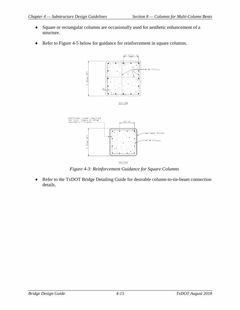
♦ Square or rectangular columns are occasionally used for aesthetic enhancement of a structure.
♦ Refer to Figure 4-5 below for guidance for reinforcement in square columns.
Figure 4-3: Reinforcement Guidance for Square Columns
♦ Refer to the TxDOT Bridge Detailing Guide for desirable column-to-tie-beam connection details.

Chapter 4 — Substructure Design Guidelines Section 9 — Columns for Single Column Bents
Bridge Design Guide 4-16 TxDOT August 2018
Section 9 Columns for Single Column Bents
Structural Analysis
For typical bridges only:
♦ For columns taller than 100 ft., consider wind loads more appropriate for the location and height.
♦ Longitudinal and transverse moments must be magnified separately for P-delta effects using the method in <Article 4> or with a second order analysis computer program.
♦ Effective length factor may be taken as 2.0 in both directions unless restraints provided by the superstructure sufficiently limit secondary moments.
♦ Refine designs by limiting longitudinal deflections to the maximum movement allowed due to joint closure. This value can be determined by taking the total number of joints along the entire bridge length minus 1 plus the thermal contraction along half the unit of the critical bent for joint closure.
Chapter 4 — Substructure Design Guidelines Section 10 — Design Resources
Bridge Design Guide 4-17 TxDOT August 2018
Section 10 Design Resources
For additional information on LRFD bridge design as implemented by TxDOT, consult the following resources:
♦ Bridge Design Manual-LRFD
♦ Design Software Programs http://www.txdot.gov/inside-txdot/division/information-technology/engineering-software.html
Bridge Design Guide 5-1 TxDOT August 2018
Chapter 5 Other Design Guidance
Contents: Section 1 — Bridge Widening Guidance ............................................................................. 5-2
Section 2 — Steel-Reinforced Elastomeric Bearings for Pretensioned Concrete Beams .... 5-4
Section 3 — Approach Slabs ................................................................................................ 5-5
Section 4 — Strut-and-Tie Method ...................................................................................... 5-8
Chapter 5 — Other Design Guidance Section 1 — Bridge Widening Guidance
Bridge Design Guide 5-2 TxDOT August 2018
Section 1 Bridge Widening Guidance
Cast-in-Place Slab Spans
Cast-in-place slab spans can be widened with cast-in-place slab spans. Skewed slabs with the main reinforcing perpendicular to the bents will be weak if the edge beam is removed under traffic. The edge should be shored under this condition. Alternatively, dowels can be grouted into the existing slab edge and the widening placed with reinforcing parallel to the centerline of the roadway. Curbs may be removed after the new slab has cured.
Widening of FS Bridges is not recommended. FS slabs should be replaced.
Cast-in-Place Concrete Girders
Concrete girder spans can be widened with concrete girders, prestressed beams, or prestressed box beams. Prestressed beams are recommended. Box beams may be used if depth is an issue.
Pan Form Girders
Pan form girders can be widened with pan forms, prestressed box beams, or prestressed slab beams. Pan forms are recommended.
Steel I-Beam
Steel I-beam spans can be widened with prestressed TxGirders or steel I beams. Prestressed TxGirders are recommended. Steel I beams may be used if depth, framing, or aesthetics is an issue.
Continuous Steel I-Beam
Continuous steel I-beam units can be widened with prestressed beams or steel I beams. Simple-span prestressed girders with the slab continuous are recommended. The slab should have standard reinforcing and be tied to the existing slab.
Cantilever/Drop-In Steel I-Beam
Cantilever/drop-in steel I-beam units can be widened with prestressed concrete girders or continuous steel I beams. Simple-span prestressed beams are recommended with expansion joints over the bents connected by longitudinal open joints to the existing expansion joint at the notches.
Chapter 5 — Other Design Guidance Section 1 — Bridge Widening Guidance
Bridge Design Guide 5-3 TxDOT August 2018
Continuous Steel Plate Girders
Continuous steel plate girder units can be widened with continuous steel plate girders or with prestressed beams if the span is 150 ft. or less.
Prestressed Concrete Beams and Girders
Prestressed concrete beam and girder spans and units should be widened in kind.
Dowels
Widenings may require additional dowels. See the guidelines for abutments, interior bents, and inverted tees for maximum recommended space between dowels. If a full depth joint is used between the existing and the widened, the widened portion should have dowels per the guidance for abutments, interior bents and inverted tee bents.
Chapter 5 — Other Design Guidance Section 2 — Steel-Reinforced Elastomeric Bearings
for Pretensioned Concrete Beams
Bridge Design Guide 5-4 TxDOT August 2018
Section 2 Steel-Reinforced Elastomeric Bearings for Pretensioned Concrete Beams
Geometric Constraints
Rectangular pads are preferred over round pads, which make it harder to satisfy rotation requirements.
Structural Analysis
Expanding length of prestressed concrete beam units can be taken as 1/2 total unit length. For highly skewed bridges and very wide bridges, take expanding length on a diagonal between slab corners to obtain the most unfavorable expansion length.
Design Criteria
For Design Method A in <Article 14.7.6>, shape factor S is preferred to be between 10 and 12.
Chapter 5 — Other Design Guidance Section 3 — Approach Slabs
Bridge Design Guide 5-5 TxDOT August 2018
Section 3 Approach Slabs
Geometric Constraints
Supporting an approach slab on wing walls is strongly discouraged. Compaction of backfill is difficult and loss of backfill material can occur. Without the bearing on the backfill, the approach slab is supported on only three sides (at the two wing walls and the abutment backwall), and the standard approach slab is not reinforced for this situation nor are the wing walls designed to carry the load. The approach slab should be supported by the abutment wall and approach backfill only, and appropriate backfill material is essential. TxDOT supports the placement of a cement-stabilized abutment backfill (CSAB) wedge in the zone behind the abutment. CSAB solves the problem of difficult compaction behind the abutment, and it resists the moisture gain and loss of material common under approach slabs.
Beginning of the Bridge Bump
There are many mechanisms that cause the bump at the beginning of bridges. The main reasons can be caused by the following:
♦ Consolidation settlement of foundation soil
♦ Poor compaction and consolidation of backfill material
♦ Poor drainage and soil erosion
♦ Traffic volume
Mitigation Techniques
Mitigation techniques to remove or lessen the bump at the beginning of the bridge for bridge approaches are:
♦ Improvement of the embankment foundation soil – if the foundation soils are too weak to support the embankment, they can be improved by:
• Excavation and replacement
• Preloading/precompression
• Dynamic Compaction
• Stone Columns, compaction piles, auger cast piles, deep soil mixing
♦ Improvement of Approach Embankment/Backfill Material
Chapter 5 — Other Design Guidance Section 3 — Approach Slabs
Bridge Design Guide 5-6 TxDOT August 2018
• Use high quality fill – limit the percentage of fines and ensure that the material is properly compacted. Compaction of fill adjacent to the back wall and wingwalls can be problematic.
• Use cement stabilized abutment backfill (CSAB) or flowable fill – this solves the compaction problems and is resistant to moisture gain and loss of material.
♦ Effective Drainage and Erosion Control Methods
• Design for drainage of the bridge and where it is going once off the bridge. Avoid having water run over expansion joints particularly at abutments. Strategically placed deck drains can solve issues with water flowing under approach slabs.
• Use surface drains and/or gutter system.
• Reduce the amount of fines in the backfill and use a more porous material or CSAB
♦ Design of approach slab (more information below)
Approach Slab Use
The positive aspects of using approach slabs are as follows:
♦ Provides a smooth transition between the bridge deck and the roadway pavement.
♦ Minimizes the effect of differential settlements between the bridge abutment founded on shafts or piles and the embankment fill. An approach slab is designed to span across a section that is approximately half of its length without any problems. Consequently, they do a good job of mitigating issues with settlement behind the abutment backwall.
♦ Approach slabs are relatively economical compared to other options (i.e. pile supported embankment, grouted columns, etc.) and are a natural extension of the bridge.
♦ Approach slabs also decrease the live load effect on the abutment backwall, which decreases the lateral load and overturning of the abutment cap.
♦ Approach slabs, when properly placed, provide a seal to prevent water from seeping into the soil behind the abutment backwall and in front of the wingwall. Sealing the gap between the approach slab and the wingwalls is very important.
♦ Districts that have not used approach slabs have found that the maintenance required to minimize the bump at the end of the bridge is very high. This is especially true in swelling clays, where during the dry times the clay shrinks so additional asphalt is placed and then during wet times the clay swells so the asphalt has to be milled off. This can become bothersome after a couple of wet/dry cycles.
The negative aspects of using approach slabs are as follows:
Chapter 5 — Other Design Guidance Section 3 — Approach Slabs
Bridge Design Guide 5-7 TxDOT August 2018
♦ Voids can develop under the approach slabs. The size of the void depends upon what is the cause of it. For example, most approach slabs have a small gap (< 1 inch) between the approach slab and the soil immediately behind the abutment backwall, which is due to the settlement of the soil. This gap is not a problem, as the approach slab is designed to span over sections like this. However, if there is considerable settlement or water erosion behind the abutment backwall, the void can be fairly significant in size and if left unfilled could potentially grow in size. This would need to be filled in with flowable backfill. (It should be noted that in the event of considerable settlement or erosion due to water seepage behind the backwall, if the approach slab wasn’t present there would considerable and constant maintenance required to maintain a nearly constant grade for the roadway.)
♦ If the entire embankment settles then the approach slab can become tilted. The portion of the approach slab that is connected to the backwall would remain fixed but the end away from the backwall would settle. This would create a bump at the end of the approach slab. This would also be problematic for roadway/bridges without an approach slab.
Chapter 5 — Other Design Guidance Section 4 — Strut-and-Tie Method
Bridge Design Guide 5-8 TxDOT August 2018
Section 4 Strut-and-Tie Method
Structural Analysis
Place nodes at applied loads and reactions. More nodes can be added as long as the tension ties are located where reinforcement is normally placed. In general, nodes need to be located at the center of the tension ties and compression struts. If there is sufficient concrete in the incoming member the strut can be considered within both members, such as in the case with a column and a footing, and the nodes can be placed where the two members meet.
A 3 dimensional truss can be broken into multiple 2 dimensional trusses to be analyzed. When analyzing the 2 dimensional trusses, use the same reactions as the 3 dimensional truss, but recalculate the applied loads so equilibrium is satisfied.
Guidelines
The tension tie reinforcement must be close enough to the drilled shaft to be considered in the truss analysis. Therefore, the tension tie reinforcement must be within a 45 degree distribution angle (i.e. no more than dc away from the member on either side).
Use strut bearing lengths proportional to the amount of load carried by the strut at a node.
Conservatively assume the width of a strut in a CCC node, hs, as the height of the compression block.
Bridge Design Guide 6-1 TxDOT August 2018
Chapter 6 Frequently Asked Questions
Contents: Section 1 — Overview .......................................................................................................... 6-2
Section 2 — FAQ’s .............................................................................................................. 6-3
Chapter 6 — Frequently Asked Questions Section 1 — Overview
Bridge Design Guide 6-2 TxDOT August 2018
Section 1 Overview
The Bridge Division receives regular questions on a daily basis. This Chapter captures some of the most frequently asked questions.
Chapter 6 — Frequently Asked Questions Section 2 — FAQ’s
Bridge Design Guide 6-3 TxDOT August 2018
Section 2 FAQ’s
Why is Texas disregarding the requirement specified for 25 percent of the combined axle loads?
The braking force in the AASHTO LRFD Bridge Design Specifications is significantly larger than what was specified in the AASHTO Standard Specifications for highway bridges. This increased load is not justified for Texas.
Why is the minimum spacing for reinforcement in conventional rectangular caps set at 4 inches instead of 3 inches?
The minimum is set at 4 inches for vertical space between rows and 3 inches for horizontal space. This allows for adequate consolidation of concrete.

Bridge Design Guide A-1 TxDOT August 2018
Appendix A Pretensioned Concrete TxGirder Haunch Design Guide
Contents: Section 1 — Components of Haunch .......................................................................................2
Section 2 — Minimum and Maximum Haunch Values ...........................................................5
Section 3 — Steps to Calculate Haunch ...................................................................................6
Section 4 — Vertical Curve Effects on Haunch .....................................................................10
Section 5 — Superelevation Transition Effects on Haunch ...................................................12
Section 6 — Example TxGirder Haunch Calculations ...........................................................15
Appendix A — Pretensioned Concrete TxGirder Haunch Design Guide Section 1 — Components of Haunch
Bridge Design Guide A-2 TxDOT August 2018
Section 1 Components of Haunch
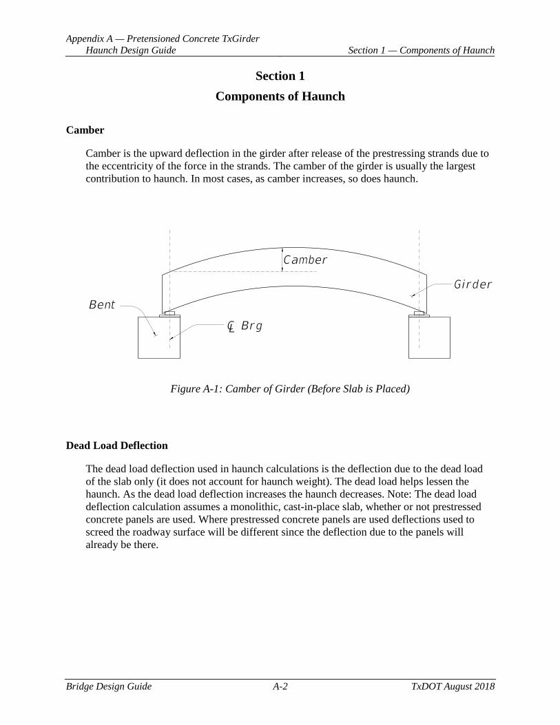
Camber
Camber is the upward deflection in the girder after release of the prestressing strands due to the eccentricity of the force in the strands. The camber of the girder is usually the largest contribution to haunch. In most cases, as camber increases, so does haunch.
Figure A-1: Camber of Girder (Before Slab is Placed)
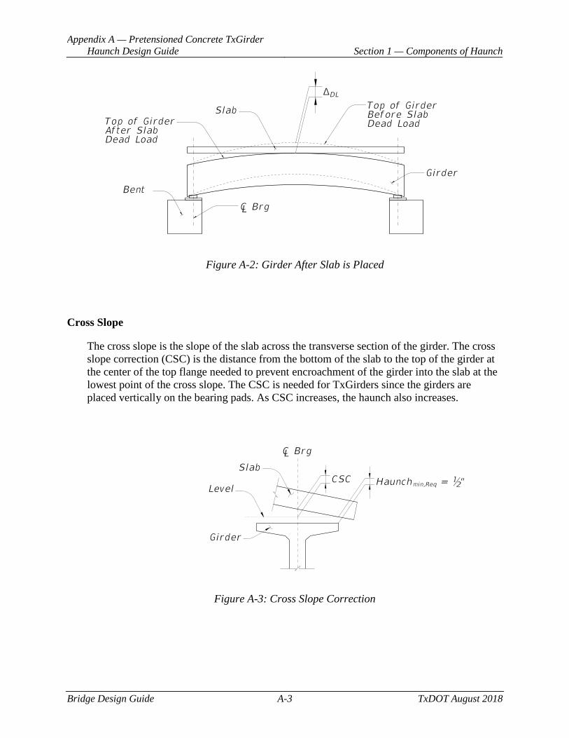
Dead Load Deflection
The dead load deflection used in haunch calculations is the deflection due to the dead load of the slab only (it does not account for haunch weight). The dead load helps lessen the haunch. As the dead load deflection increases the haunch decreases. Note: The dead load deflection calculation assumes a monolithic, cast-in-place slab, whether or not prestressed concrete panels are used. Where prestressed concrete panels are used deflections used to screed the roadway surface will be different since the deflection due to the panels will already be there.
Appendix A — Pretensioned Concrete TxGirder Haunch Design Guide Section 1 — Components of Haunch
Bridge Design Guide A-3 TxDOT August 2018
Figure A-2: Girder After Slab is Placed
Cross Slope
The cross slope is the slope of the slab across the transverse section of the girder. The cross slope correction (CSC) is the distance from the bottom of the slab to the top of the girder at the center of the top flange needed to prevent encroachment of the girder into the slab at the lowest point of the cross slope. The CSC is needed for TxGirders since the girders are placed vertically on the bearing pads. As CSC increases, the haunch also increases.
Figure A-3: Cross Slope Correction
Appendix A — Pretensioned Concrete TxGirder Haunch Design Guide Section 1 — Components of Haunch
Bridge Design Guide A-4 TxDOT August 2018
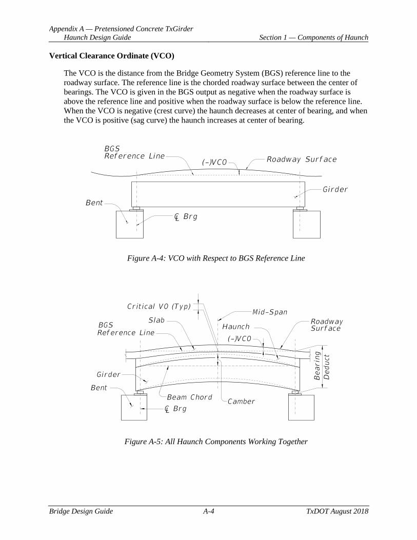
Vertical Clearance Ordinate (VCO)
The VCO is the distance from the Bridge Geometry System (BGS) reference line to the roadway surface. The reference line is the chorded roadway surface between the center of bearings. The VCO is given in the BGS output as negative when the roadway surface is above the reference line and positive when the roadway surface is below the reference line. When the VCO is negative (crest curve) the haunch decreases at center of bearing, and when the VCO is positive (sag curve) the haunch increases at center of bearing.
Figure A-4: VCO with Respect to BGS Reference Line
Figure A-5: All Haunch Components Working Together
Appendix A — Pretensioned Concrete TxGirder Haunch Design Guide
Section 2 — Minimum and Maximum Haunch Values
Bridge Design Guide A-5 TxDOT August 2018
Section 2 Minimum and Maximum Haunch Values
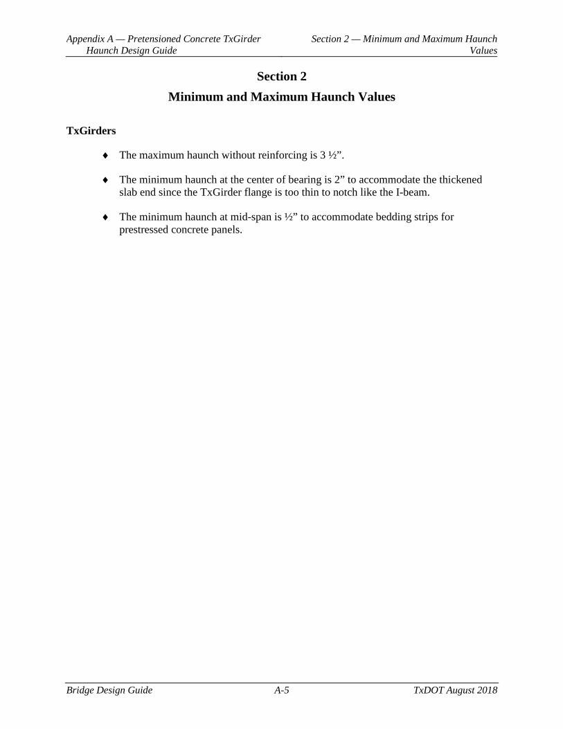
TxGirders
♦ The maximum haunch without reinforcing is 3 ½”.
♦ The minimum haunch at the center of bearing is 2” to accommodate the thickened slab end since the TxGirder flange is too thin to notch like the I-beam.
♦ The minimum haunch at mid-span is ½” to accommodate bedding strips for prestressed concrete panels.
Appendix A — Pretensioned Concrete TxGirder Haunch Design Guide Section 3 — Steps to Calculate Haunch
Bridge Design Guide A-6 TxDOT August 2018
Section 3 Steps to Calculate Haunch
This section applies to simple geometric cases only. Refer to Section 4 for guidance on complex geometry.
Step 1
Execute a preliminary BGS run using a beam framing option from 1-10 in the FOPT card. On the BRNG card, input a “Depth Below the Reference Line”, or bearing deduct, of zero. This gives the VCLR output as the VCO defined above. Include a VCLR card for each span with the bridge alignment as the specified alignment.
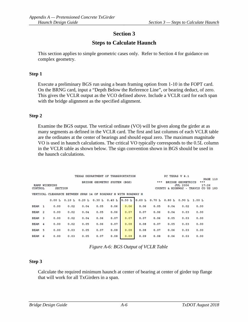
Step 2
Examine the BGS output. The vertical ordinate (VO) will be given along the girder at as many segments as defined in the VCLR card. The first and last columns of each VCLR table are the ordinates at the center of bearings and should equal zero. The maximum magnitude VO is used in haunch calculations. The critical VO typically corresponds to the 0.5L column in the VCLR table as shown below. The sign convention shown in BGS should be used in the haunch calculations.
Figure A-6: BGS Output of VCLR Table
Step 3
Calculate the required minimum haunch at center of bearing at center of girder top flange that will work for all TxGirders in a span.
Appendix A — Pretensioned Concrete TxGirder Haunch Design Guide Section 3 — Steps to Calculate Haunch
Bridge Design Guide A-7 TxDOT August 2018
HaunchCL Brg,Req = (C – 0.8ΔDL) + VCO + CSC + Haunchmin,Req
Where:
C = Camber of the TxGirder, ft (taken from PGSuper “TxDOT Summary Report” under “Camber and Deflections”, the Design Camber. Design Camber includes girder self-weight deflection, camber at release, and camber due to creep. NOTE: PGSuper gives camber in inches and feet. The camber will need to be in feet for the above equation.)
ΔDL = Absolute value of dead load deflection of TxGirder at midspan due to a cast-in-place slab, ft (taken from PGSuper “TxDOT Summary Report” under “Camber and Deflection” for deflections of Slab and Diaphragms. NOTE: PGSuper gives dead load deflection in inches and feet. The dead load deflection will need to be in feet for the above equation.)
VCO = Maximum magnitude vertical clearance ordinate, ft (taken from BGS VCLR output table; keep BGS sign convention)
CSC = Cross slope correction, ft (this equation assumes a constant cross slope above the girder top flange)
CSC = CS x ½(wf)
Where:
CS = Cross slope of slab above girder top flange, ft/ft
wf = Width of top flange, ft
Haunchmin,Req = Minimum required haunch measured at the least-haunch edge of the girder flange. Minimum haunch typically occurs at mid-span. However, with large crest curves and superelevation transitions, Minimum Haunch can occur anywhere along the beam.
Use the largest HaunchCL Brg,Re q value for each girder in that span:
HaunchCL Brg = max{ HaunchCL Brg,Req} (round up to the nearest ¼″)
HaunchCL Brg is the haunch that will be provided at center of bearing for each TxGirder in that span.
Appendix A — Pretensioned Concrete TxGirder Haunch Design Guide Section 3 — Steps to Calculate Haunch
Bridge Design Guide A-8 TxDOT August 2018
Step 4
Calculate the theoretical minimum haunch along center of girder top flange.
Haunchmin = HaunchCL Brg – (C – 0.8ΔDL) – VCO – CSC
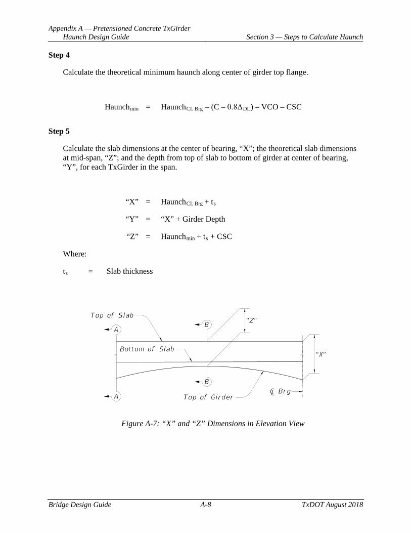
Step 5
Calculate the slab dimensions at the center of bearing, “X”; the theoretical slab dimensions at mid-span, “Z”; and the depth from top of slab to bottom of girder at center of bearing, “Y”, for each TxGirder in the span.
“X” = HaunchCL Brg + ts
“Y” = “X” + Girder Depth
“Z” = Haunchmin + ts + CSC
Where:
ts = Slab thickness
Figure A-7: “X” and “Z” Dimensions in Elevation View
Appendix A — Pretensioned Concrete TxGirder Haunch Design Guide Section 3 — Steps to Calculate Haunch
Bridge Design Guide A-9 TxDOT August 2018
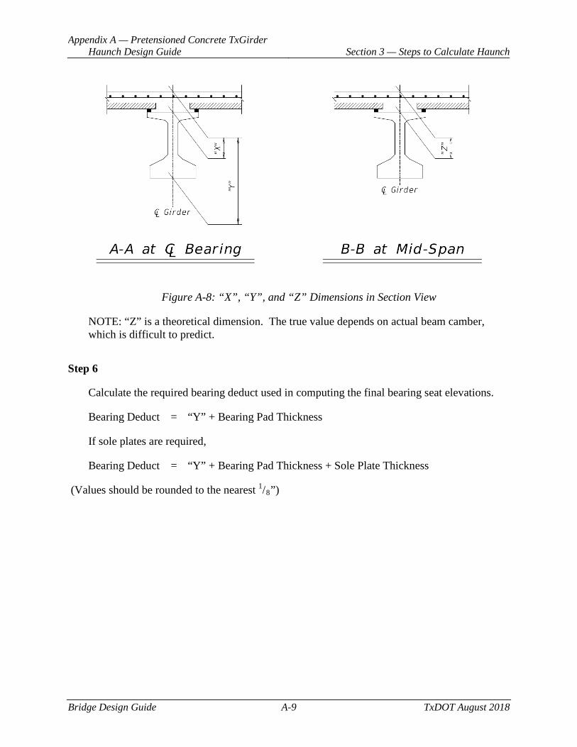
Figure A-8: “X”, “Y”, and “Z” Dimensions in Section View
NOTE: “Z” is a theoretical dimension. The true value depends on actual beam camber, which is difficult to predict.
Step 6
Calculate the required bearing deduct used in computing the final bearing seat elevations.
Bearing Deduct = “Y” + Bearing Pad Thickness
If sole plates are required,
Bearing Deduct = “Y” + Bearing Pad Thickness + Sole Plate Thickness
(Values should be rounded to the nearest 1/8”)
Appendix A — Pretensioned Concrete TxGirder Haunch Design Guide Section 4 — Vertical Curve Effects on Haunch
Bridge Design Guide A-10 TxDOT August 2018
Section 4 Vertical Curve Effects on Haunch
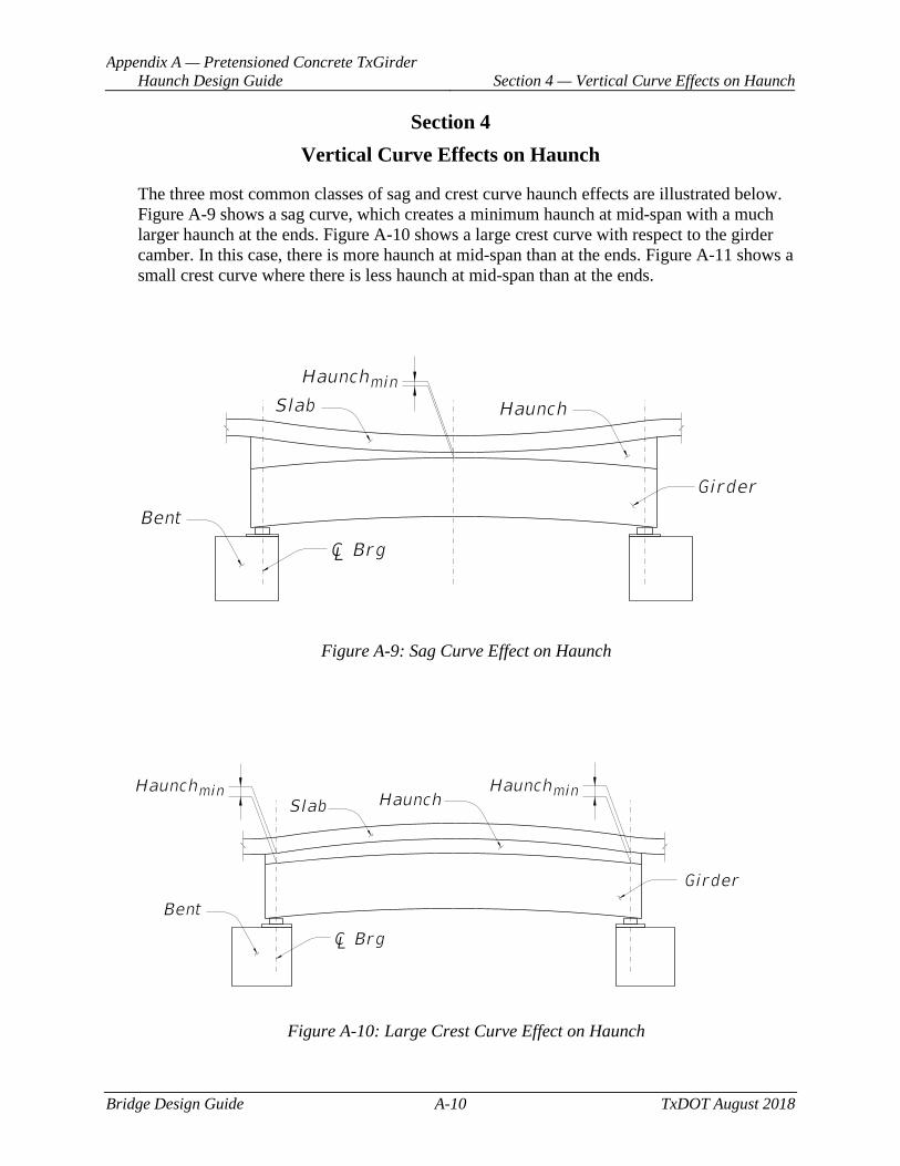
The three most common classes of sag and crest curve haunch effects are illustrated below. Figure A-9 shows a sag curve, which creates a minimum haunch at mid-span with a much larger haunch at the ends. Figure A-10 shows a large crest curve with respect to the girder camber. In this case, there is more haunch at mid-span than at the ends. Figure A-11 shows a small crest curve where there is less haunch at mid-span than at the ends.
Figure A-9: Sag Curve Effect on Haunch
Figure A-10: Large Crest Curve Effect on Haunch

Appendix A — Pretensioned Concrete TxGirder Haunch Design Guide Section 4 — Vertical Curve Effects on Haunch
Bridge Design Guide A-11 TxDOT August 2018
Figure A-11: Small Crest Curve Effect on Haunch
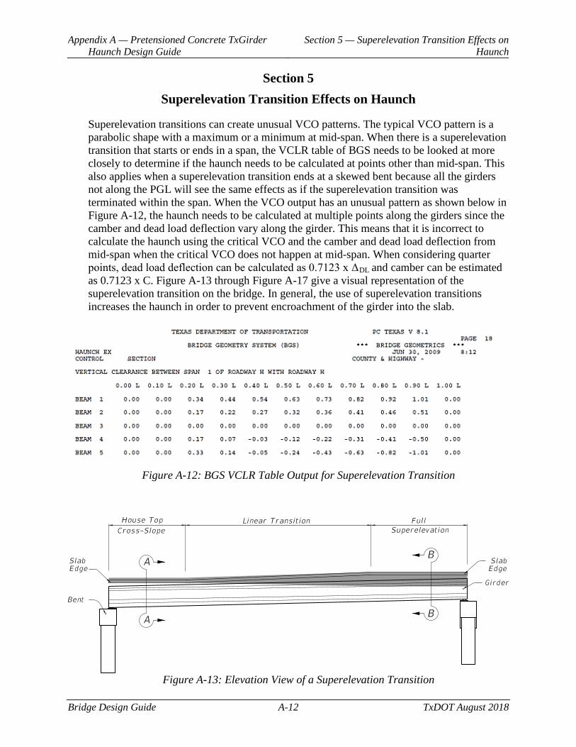
Appendix A — Pretensioned Concrete TxGirder Haunch Design Guide
Section 5 — Superelevation Transition Effects on Haunch
Bridge Design Guide A-12 TxDOT August 2018
Section 5 Superelevation Transition Effects on Haunch
Superelevation transitions can create unusual VCO patterns. The typical VCO pattern is a parabolic shape with a maximum or a minimum at mid-span. When there is a superelevation transition that starts or ends in a span, the VCLR table of BGS needs to be looked at more closely to determine if the haunch needs to be calculated at points other than mid-span. This also applies when a superelevation transition ends at a skewed bent because all the girders not along the PGL will see the same effects as if the superelevation transition was terminated within the span. When the VCO output has an unusual pattern as shown below in Figure A-12, the haunch needs to be calculated at multiple points along the girders since the camber and dead load deflection vary along the girder. This means that it is incorrect to calculate the haunch using the critical VCO and the camber and dead load deflection from mid-span when the critical VCO does not happen at mid-span. When considering quarter points, dead load deflection can be calculated as 0.7123 x ΔDL and camber can be estimated as 0.7123 x C. Figure A-13 through Figure A-17 give a visual representation of the superelevation transition on the bridge. In general, the use of superelevation transitions increases the haunch in order to prevent encroachment of the girder into the slab.
Figure A-12: BGS VCLR Table Output for Superelevation Transition
Figure A-13: Elevation View of a Superelevation Transition
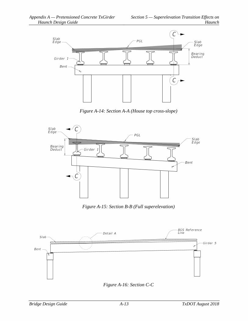
Appendix A — Pretensioned Concrete TxGirder Haunch Design Guide
Section 5 — Superelevation Transition Effects on Haunch
Bridge Design Guide A-13 TxDOT August 2018
Figure A-14: Section A-A (House top cross-slope)
Figure A-15: Section B-B (Full superelevation)
Figure A-16: Section C-C
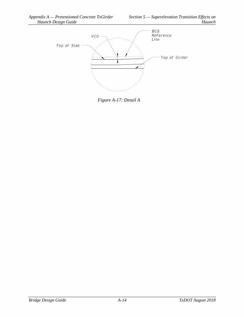
Appendix A — Pretensioned Concrete TxGirder Haunch Design Guide
Section 5 — Superelevation Transition Effects on Haunch
Bridge Design Guide A-14 TxDOT August 2018
Figure A-17: Detail A
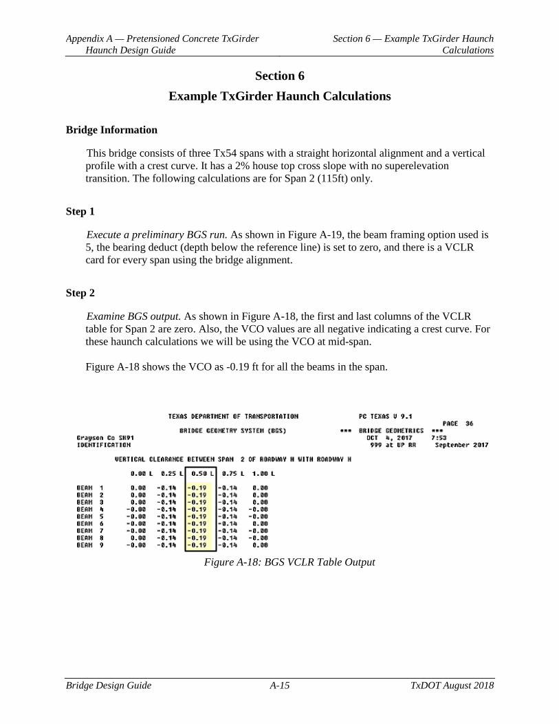
Appendix A — Pretensioned Concrete TxGirder Haunch Design Guide
Section 6 — Example TxGirder Haunch Calculations
Bridge Design Guide A-15 TxDOT August 2018
Section 6 Example TxGirder Haunch Calculations
Bridge Information
This bridge consists of three Tx54 spans with a straight horizontal alignment and a vertical profile with a crest curve. It has a 2% house top cross slope with no superelevation transition. The following calculations are for Span 2 (115ft) only.
Step 1
Execute a preliminary BGS run. As shown in Figure A-19, the beam framing option used is 5, the bearing deduct (depth below the reference line) is set to zero, and there is a VCLR card for every span using the bridge alignment.
Step 2
Examine BGS output. As shown in Figure A-18, the first and last columns of the VCLR table for Span 2 are zero. Also, the VCO values are all negative indicating a crest curve. For these haunch calculations we will be using the VCO at mid-span. Figure A-18 shows the VCO as -0.19 ft for all the beams in the span.
Figure A-18: BGS VCLR Table Output
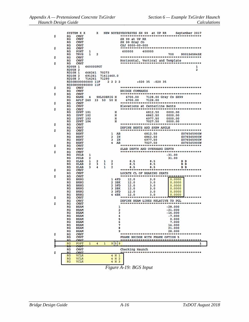
Appendix A — Pretensioned Concrete TxGirder Haunch Design Guide
Section 6 — Example TxGirder Haunch Calculations
Bridge Design Guide A-16 TxDOT August 2018
Figure A-19: BGS Input
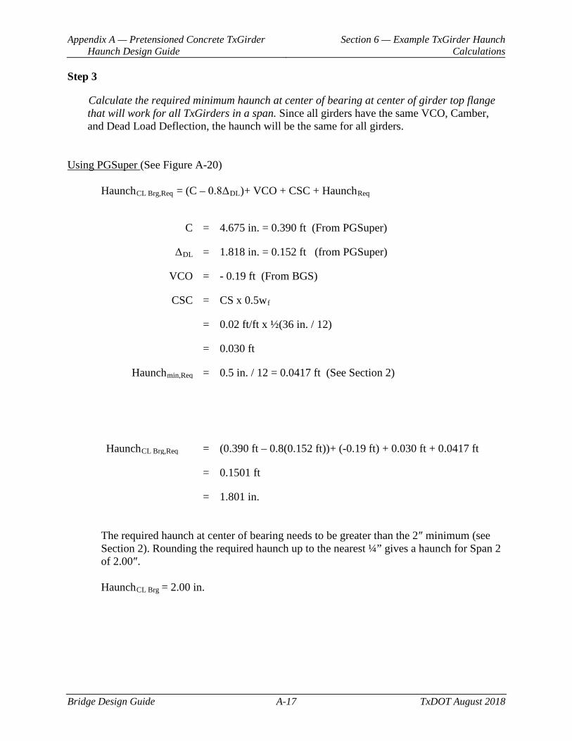
Appendix A — Pretensioned Concrete TxGirder Haunch Design Guide
Section 6 — Example TxGirder Haunch Calculations
Bridge Design Guide A-17 TxDOT August 2018
Step 3
Calculate the required minimum haunch at center of bearing at center of girder top flange that will work for all TxGirders in a span. Since all girders have the same VCO, Camber, and Dead Load Deflection, the haunch will be the same for all girders.
Using PGSuper (See Figure A-20)
HaunchCL Brg,Req = (C – 0.8ΔDL)+ VCO + CSC + HaunchReq
C = 4.675 in. = 0.390 ft (From PGSuper)
ΔDL = 1.818 in. = 0.152 ft (from PGSuper)
VCO = - 0.19 ft (From BGS)
CSC = CS x 0.5wf
= 0.02 ft/ft x ½(36 in. / 12)
= 0.030 ft
Haunchmin,Req = 0.5 in. / 12 = 0.0417 ft (See Section 2)
HaunchCL Brg,Req = (0.390 ft – 0.8(0.152 ft))+ (-0.19 ft) + 0.030 ft + 0.0417 ft
= 0.1501 ft
= 1.801 in.
The required haunch at center of bearing needs to be greater than the 2″ minimum (see Section 2). Rounding the required haunch up to the nearest ¼” gives a haunch for Span 2 of 2.00″. HaunchCL Brg = 2.00 in.
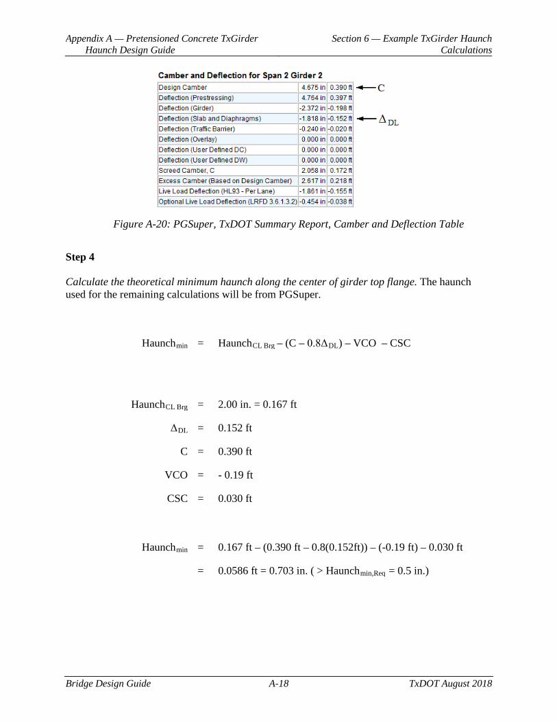
Appendix A — Pretensioned Concrete TxGirder Haunch Design Guide
Section 6 — Example TxGirder Haunch Calculations
Bridge Design Guide A-18 TxDOT August 2018
Figure A-20: PGSuper, TxDOT Summary Report, Camber and Deflection Table
Step 4 Calculate the theoretical minimum haunch along the center of girder top flange. The haunch used for the remaining calculations will be from PGSuper.
Haunchmin = HaunchCL Brg – (C – 0.8ΔDL) – VCO – CSC
HaunchCL Brg = 2.00 in. = 0.167 ft
ΔDL = 0.152 ft
C = 0.390 ft
VCO = - 0.19 ft
CSC = 0.030 ft
Haunchmin = 0.167 ft – (0.390 ft – 0.8(0.152ft)) – (-0.19 ft) – 0.030 ft
= 0.0586 ft = 0.703 in. ( > Haunchmin,Req = 0.5 in.)
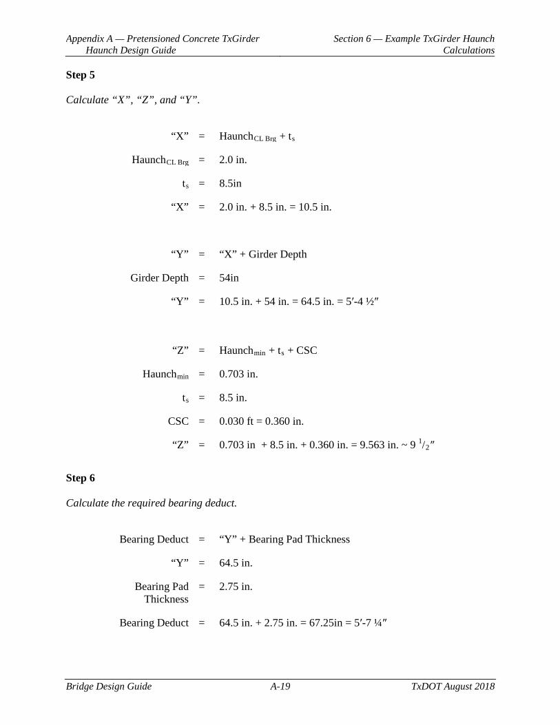
Appendix A — Pretensioned Concrete TxGirder Haunch Design Guide
Section 6 — Example TxGirder Haunch Calculations
Bridge Design Guide A-19 TxDOT August 2018
Step 5
Calculate “X”, “Z”, and “Y”.
“X” = HaunchCL Brg + ts
HaunchCL Brg = 2.0 in.
ts = 8.5in
“X” = 2.0 in. + 8.5 in. = 10.5 in.
“Y” = “X” + Girder Depth
Girder Depth = 54in
“Y” = 10.5 in. + 54 in. = 64.5 in. = 5ʹ-4 ½″
“Z” = Haunchmin + ts + CSC
Haunchmin = 0.703 in.
ts = 8.5 in.
CSC = 0.030 ft = 0.360 in.
“Z” = 0.703 in + 8.5 in. + 0.360 in. = 9.563 in. ~ 9 1/2″
Step 6
Calculate the required bearing deduct.
Bearing Deduct = “Y” + Bearing Pad Thickness
“Y” = 64.5 in.
Bearing Pad Thickness
= 2.75 in.
Bearing Deduct = 64.5 in. + 2.75 in. = 67.25in = 5ʹ-7 ¼″
Bridge Design Guide B-1 TxDOT August 2018
Appendix B Pretensioned Concrete U Beam Design Guide
Contents: Section 1 — Bearing Pad Taper Calculations for U Beams .....................................................2
Section 2 — Haunch Calculations for U Beams ......................................................................6
Section 3 — Beam Framing ...................................................................................................16
Section 4 — Restraining Superstructure Lateral Movement ..................................................17
Appendix B — Pretensioned Concrete U Beam Design Guide
Section 1 — Bearing Pad Taper Calculations for U Beams
Bridge Design Guide B-2 TxDOT August 2018
Section 1 Bearing Pad Taper Calculations for U Beams
Bearing Pad Taper
The bearing seat for a U beam is level perpendicular to the centerline of bearing but slopes along the centerline of bearing between the left and right bearing seat elevations. The bearing pad is oriented along the centerline of bearing. This configuration for the U-beam bearing allows the pad to taper in only one direction (perpendicular to the centerline of bearing). The amount of bearing pad taper depends on three factors:
♦ Grade of the U beam
♦ Slope of the bearing seat (taper is along ¡ Brg)
♦ Beam angle (angle between ¡ Beam and ¡ Brg in plan view)
All U-beam projects should have a Bearing Pad Taper Report sheet that contains the various pad tapers for use by the bearing pad fabricator. This report summarizes the bearing pad taper perpendicular to the centerline of bearing for each beam bearing location. In BGS, the report is titled “Bearing Pad Taper -- Fabricator’s Report”. The calculations that follow derive the formula for calculating the bearing pad taper perpendicular to centerline of bearing.
For purposes of developing the formulas for calculating bearing pad taper, the following sign convention will be used looking in the direction of increasing station numbers:
♦ Positive bearing seat slope is up and to the right
♦ Negative bearing seat slope is down and to the right
♦ Positive beam grade is up
♦ Negative beam grade is down
♦ Positive bearing pad taper is up
♦ Negative bearing pad taper is down
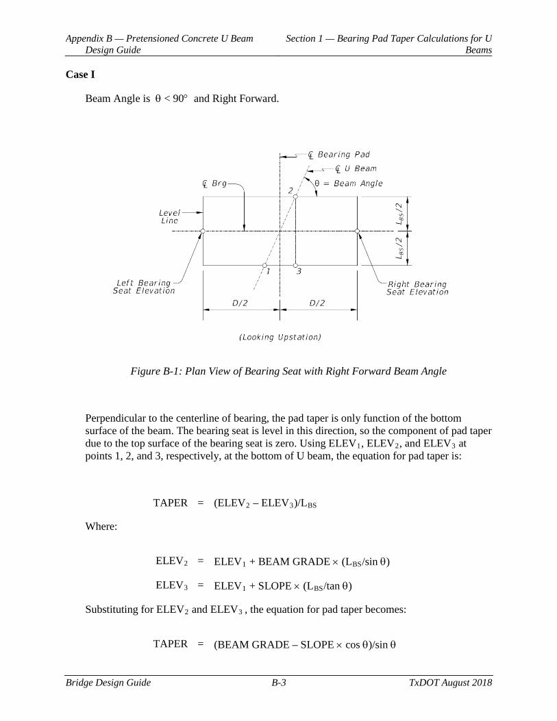
Appendix B — Pretensioned Concrete U Beam Design Guide
Section 1 — Bearing Pad Taper Calculations for U Beams
Bridge Design Guide B-3 TxDOT August 2018
Case I
Beam Angle is θ < 90° and Right Forward.
Figure B-1: Plan View of Bearing Seat with Right Forward Beam Angle
Perpendicular to the centerline of bearing, the pad taper is only function of the bottom surface of the beam. The bearing seat is level in this direction, so the component of pad taper due to the top surface of the bearing seat is zero. Using ELEV1, ELEV2, and ELEV3 at points 1, 2, and 3, respectively, at the bottom of U beam, the equation for pad taper is:
TAPER = (ELEV2 – ELEV3)/LBS
Where:
ELEV2 = ELEV1 + BEAM GRADE × (LBS/sin θ)
ELEV3 = ELEV1 + SLOPE × (LBS/tan θ)
Substituting for ELEV2 and ELEV3 , the equation for pad taper becomes:
TAPER = (BEAM GRADE – SLOPE × cos θ)/sin θ
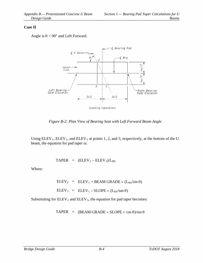
Appendix B — Pretensioned Concrete U Beam Design Guide
Section 1 — Bearing Pad Taper Calculations for U Beams
Bridge Design Guide B-4 TxDOT August 2018
Case II
Angle is θ < 90° and Left Forward.
Figure B-2: Plan View of Bearing Seat with Left Forward Beam Angle
Using ELEV1, ELEV2, and ELEV3 at points 1, 2, and 3, respectively, at the bottom of the U beam, the equation for pad taper is:
TAPER = (ELEV2 – ELEV3)/LBS
Where:
ELEV2 = ELEV1 + BEAM GRADE × (LBS/sin θ)
ELEV3 = ELEV1 – SLOPE × (LBS/tan θ)
Substituting for ELEV2 and ELEV3, the equation for pad taper becomes:
TAPER = (BEAM GRADE + SLOPE × cos θ)/sin θ
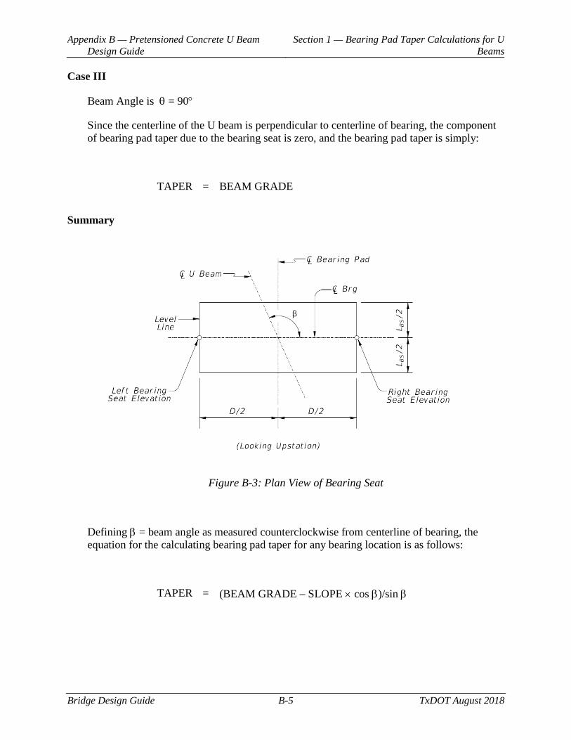
Appendix B — Pretensioned Concrete U Beam Design Guide
Section 1 — Bearing Pad Taper Calculations for U Beams
Bridge Design Guide B-5 TxDOT August 2018
Case III
Beam Angle is θ = 90°
Since the centerline of the U beam is perpendicular to centerline of bearing, the component of bearing pad taper due to the bearing seat is zero, and the bearing pad taper is simply:
TAPER = BEAM GRADE
Summary
Figure B-3: Plan View of Bearing Seat
Defining β = beam angle as measured counterclockwise from centerline of bearing, the equation for the calculating bearing pad taper for any bearing location is as follows:
TAPER = (BEAM GRADE – SLOPE × cos β)/sin β
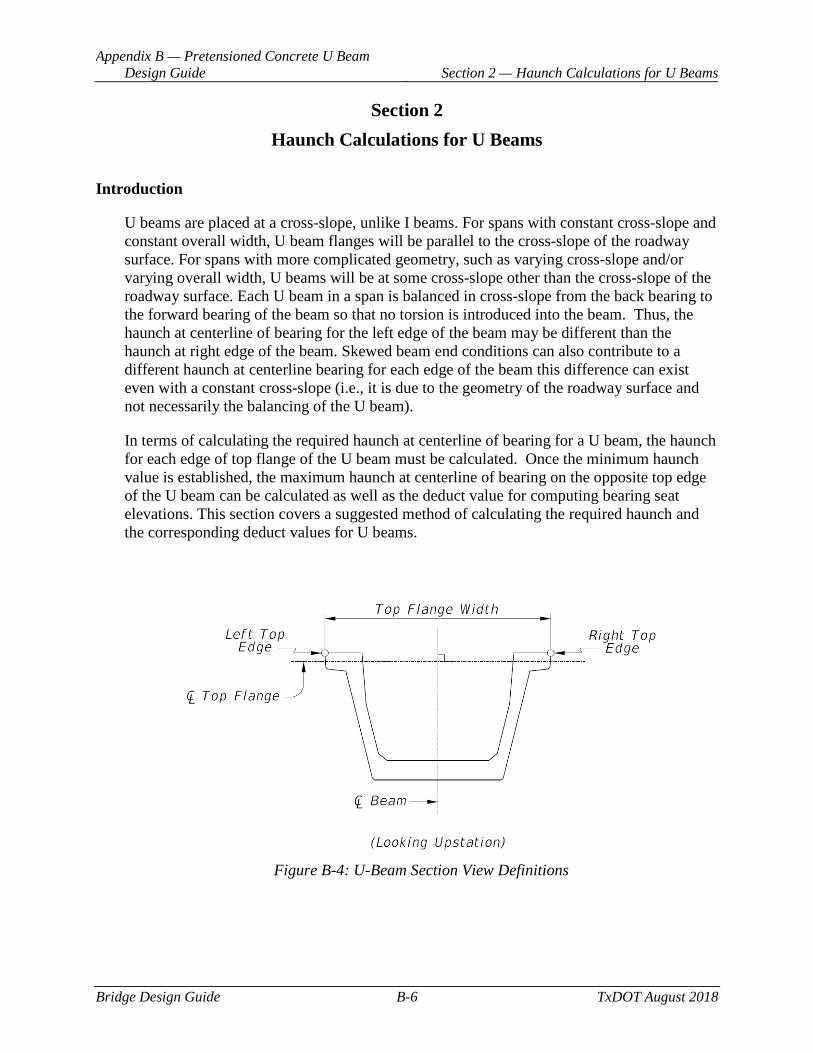
Appendix B — Pretensioned Concrete U Beam Design Guide Section 2 — Haunch Calculations for U Beams
Bridge Design Guide B-6 TxDOT August 2018
Section 2 Haunch Calculations for U Beams
Introduction
U beams are placed at a cross-slope, unlike I beams. For spans with constant cross-slope and constant overall width, U beam flanges will be parallel to the cross-slope of the roadway surface. For spans with more complicated geometry, such as varying cross-slope and/or varying overall width, U beams will be at some cross-slope other than the cross-slope of the roadway surface. Each U beam in a span is balanced in cross-slope from the back bearing to the forward bearing of the beam so that no torsion is introduced into the beam. Thus, the haunch at centerline of bearing for the left edge of the beam may be different than the haunch at right edge of the beam. Skewed beam end conditions can also contribute to a different haunch at centerline bearing for each edge of the beam this difference can exist even with a constant cross-slope (i.e., it is due to the geometry of the roadway surface and not necessarily the balancing of the U beam).
In terms of calculating the required haunch at centerline of bearing for a U beam, the haunch for each edge of top flange of the U beam must be calculated. Once the minimum haunch value is established, the maximum haunch at centerline of bearing on the opposite top edge of the U beam can be calculated as well as the deduct value for computing bearing seat elevations. This section covers a suggested method of calculating the required haunch and the corresponding deduct values for U beams.
Figure B-4: U-Beam Section View Definitions
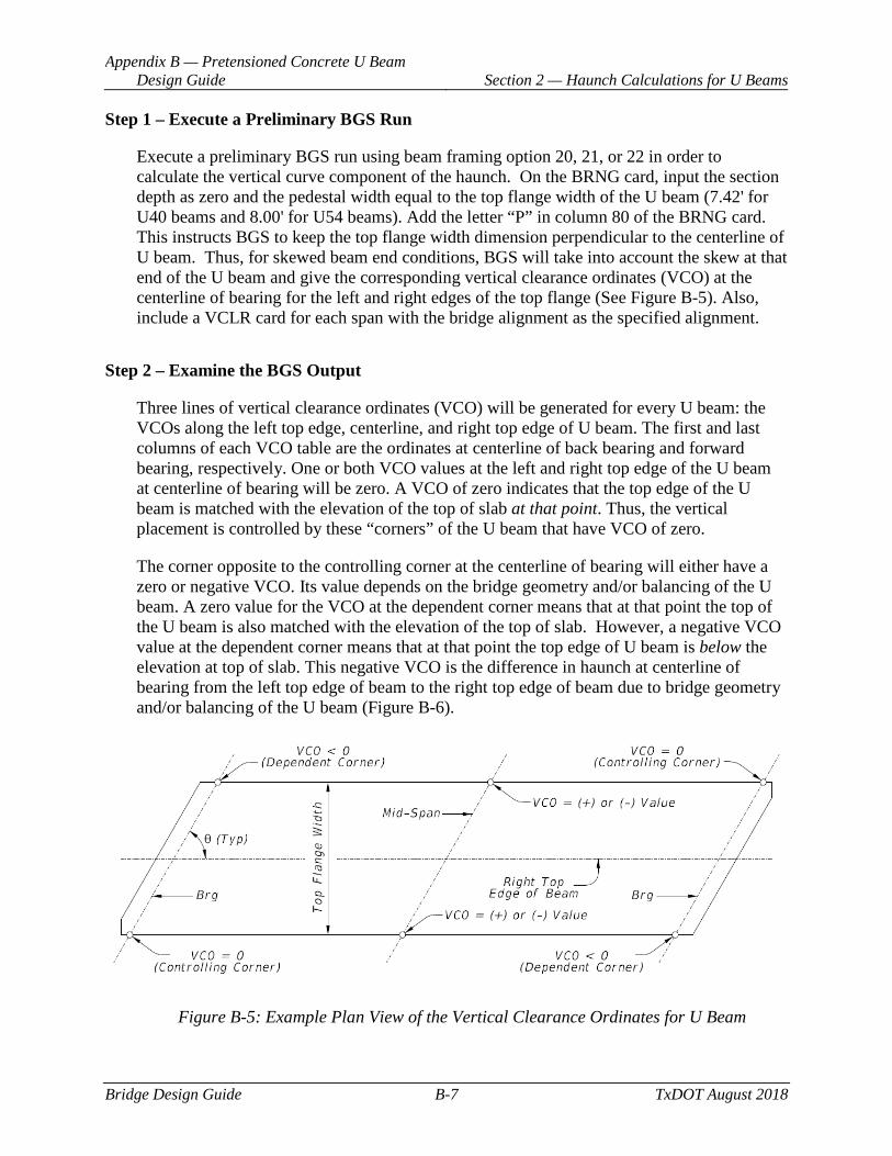
Appendix B — Pretensioned Concrete U Beam Design Guide Section 2 — Haunch Calculations for U Beams
Bridge Design Guide B-7 TxDOT August 2018
Step 1 – Execute a Preliminary BGS Run
Execute a preliminary BGS run using beam framing option 20, 21, or 22 in order to calculate the vertical curve component of the haunch. On the BRNG card, input the section depth as zero and the pedestal width equal to the top flange width of the U beam (7.42' for U40 beams and 8.00' for U54 beams). Add the letter “P” in column 80 of the BRNG card. This instructs BGS to keep the top flange width dimension perpendicular to the centerline of U beam. Thus, for skewed beam end conditions, BGS will take into account the skew at that end of the U beam and give the corresponding vertical clearance ordinates (VCO) at the centerline of bearing for the left and right edges of the top flange (See Figure B-5). Also, include a VCLR card for each span with the bridge alignment as the specified alignment.
Step 2 – Examine the BGS Output
Three lines of vertical clearance ordinates (VCO) will be generated for every U beam: the VCOs along the left top edge, centerline, and right top edge of U beam. The first and last columns of each VCO table are the ordinates at centerline of back bearing and forward bearing, respectively. One or both VCO values at the left and right top edge of the U beam at centerline of bearing will be zero. A VCO of zero indicates that the top edge of the U beam is matched with the elevation of the top of slab at that point. Thus, the vertical placement is controlled by these “corners” of the U beam that have VCO of zero.
The corner opposite to the controlling corner at the centerline of bearing will either have a zero or negative VCO. Its value depends on the bridge geometry and/or balancing of the U beam. A zero value for the VCO at the dependent corner means that at that point the top of the U beam is also matched with the elevation of the top of slab. However, a negative VCO value at the dependent corner means that at that point the top edge of U beam is below the elevation at top of slab. This negative VCO is the difference in haunch at centerline of bearing from the left top edge of beam to the right top edge of beam due to bridge geometry and/or balancing of the U beam (Figure B-6).
Figure B-5: Example Plan View of the Vertical Clearance Ordinates for U Beam

Appendix B — Pretensioned Concrete U Beam Design Guide Section 2 — Haunch Calculations for U Beams
Bridge Design Guide B-8 TxDOT August 2018
Figure B-6 illustrates the VCOs produced by BGS for the left and right top edges of the U beam when framing a span with a crest vertical curve and a varying cross-slope along the span. It is shown only to help visualize a possible scenario of VCOs produced by BGS.
Figure B-6: Example Vertical Profile at Edges of U Beam
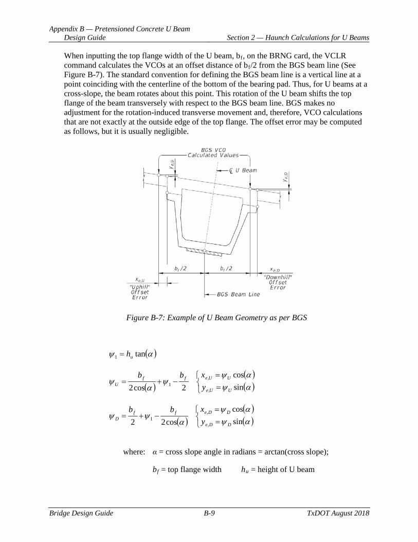
Appendix B — Pretensioned Concrete U Beam Design Guide Section 2 — Haunch Calculations for U Beams
Bridge Design Guide B-9 TxDOT August 2018
When inputting the top flange width of the U beam, bf, on the BRNG card, the VCLR command calculates the VCOs at an offset distance of bf/2 from the BGS beam line (See Figure B-7). The standard convention for defining the BGS beam line is a vertical line at a point coinciding with the centerline of the bottom of the bearing pad. Thus, for U beams at a cross-slope, the beam rotates about this point. This rotation of the U beam shifts the top flange of the beam transversely with respect to the BGS beam line. BGS makes no adjustment for the rotation-induced transverse movement and, therefore, VCO calculations that are not exactly at the outside edge of the top flange. The offset error may be computed as follows, but it is usually negligible.
Figure B-7: Example of U Beam Geometry as per BGS
( )αψ tan1 uh=
( )( )( )
==
−+=αψαψ
ψα
ψsincos
2cos2 ,
,1
UUe
UUeffU y
xbb
( )( )( )
==
−+=αψαψ
αψψ
sincos
cos22 ,
,1
DDe
DDeffD y
xbb
where: α = cross slope angle in radians = arctan(cross slope);
bf = top flange width hu = height of U beam
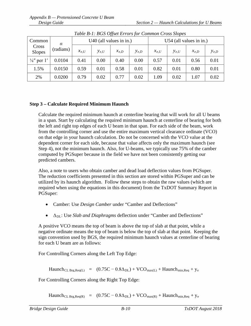
Appendix B — Pretensioned Concrete U Beam Design Guide Section 2 — Haunch Calculations for U Beams
Bridge Design Guide B-10 TxDOT August 2018
Table B-1: BGS Offset Errors for Common Cross Slopes Common
Cross Slopes
α (radians)
U40 (all values in in.) U54 (all values in in.)
xe,U ye,U xe,D ye,D xe,U ye,U xe,D ye,D
⅛″ per 1ʹ 0.0104 0.41 0.00 0.40 0.00 0.57 0.01 0.56 0.01
1.5% 0.0150 0.59 0.01 0.58 0.01 0.82 0.01 0.80 0.01
2% 0.0200 0.79 0.02 0.77 0.02 1.09 0.02 1.07 0.02
Step 3 – Calculate Required Minimum Haunch
Calculate the required minimum haunch at centerline bearing that will work for all U beams in a span. Start by calculating the required minimum haunch at centerline of bearing for both the left and right top edges of each U beam in that span. For each side of the beam, work from the controlling corner and use the entire maximum vertical clearance ordinate (VCO) on that edge in your haunch calculation. Do not be concerned with the VCO value at the dependent corner for each side, because that value affects only the maximum haunch (see Step 4), not the minimum haunch. Also, for U-beams, we typically use 75% of the camber computed by PGSuper because in the field we have not been consistently getting our predicted cambers.
Also, a note to users who obtain camber and dead load deflection values from PGSuper. The reduction coefficients presented in this section are stored within PGSuper and can be utilized by its haunch algorithm. Follow these steps to obtain the raw values (which are required when using the equations in this document) from the TxDOT Summary Report in PGSuper:
• Camber: Use Design Camber under “Camber and Deflections”
• ΔDL: Use Slab and Diaphragms deflection under “Camber and Deflections”
A positive VCO means the top of beam is above the top of slab at that point, while a negative ordinate means the top of beam is below the top of slab at that point. Keeping the sign convention used by BGS, the required minimum haunch values at centerline of bearing for each U beam are as follows:
For Controlling Corners along the Left Top Edge:
HaunchCL Brg,Req(L) = (0.75C − 0.8ΔDL) + VCOmax(L) + Haunchmin,Req + ye
For Controlling Corners along the Right Top Edge:
HaunchCL Brg,Req(R) = (0.75C − 0.8ΔDL) + VCOmax(R) + Haunchmin,Req + ye
Appendix B — Pretensioned Concrete U Beam Design Guide Section 2 — Haunch Calculations for U Beams
Bridge Design Guide B-11 TxDOT August 2018
Where:
VCOmax(L) = Maximum VCO, left top edge (usually at mid-span)
VCOmax(R) = Maximum VCO, right top edge (usually at mid-span)
C = Camber of U beam
∆DL = Dead load deflection of U beam due to slab only (no haunch)
Haunchmin,Req = The minimum required haunch (usually at mid-span) is ½″
ye = Vertical BGS Offset Error; this value is usually small and negligible. If the user wishes to account for this error, assign a positive value for the “downhill” haunch and a negative value for the “uphill” haunch.
Next, calculate the largest haunch required at a controlling corner for that span:
HaunchCL Brg(CC) = max{HaunchCL Brg,Req(L), HaunchCL Brg,Req(R)}*
* (round up to the nearest ¼″)
This haunch value will be the haunch at all controlling corners for each U beam in that span.
Now, calculate the theoretical minimum provided haunch on each side:
Haunchmin(L) = HaunchCL Brg(CC) − (0.75C − 0.8ΔDL) − VCOmax(L) − ye
Haunchmin(R) = HaunchCL Brg(CC) − (0.75C − 0.8ΔDL) − VCOmax(R) − ye
Step 4 – Calculate Maximum Haunches
Calculate the corresponding maximum haunches at centerline of bearing. The maximum haunches at centerline of bearing occur at the dependent corners of each U beam. These maximum haunches may vary between U beams in a span but typically will not vary for the same U beam. The maximum haunches at centerline of bearing for each U beam in a span are:
Appendix B — Pretensioned Concrete U Beam Design Guide Section 2 — Haunch Calculations for U Beams
Bridge Design Guide B-12 TxDOT August 2018
Left Top Edge:
HaunchCL Brg(LDC) = HaunchCL Brg(CC) − VCOLDC
Right Top Edge:
HaunchCL Brg(RDC) = HaunchCL Brg(CC) − VCORDC
Where:
VCOLDC = Vertical clearance ordinate value, dependent left top corner
VCORDC = Vertical clearance ordinate value, dependent right top corner
Step 5 – Calculate Slab Dimensions
Calculate the slab dimensions at centerline of bearing, Xmin and Xmax, and the theoretical slab dimensions at mid-span, ZL and ZR, for each U beam in the span (See Figure B-8). The equations are:
Xmin = HaunchCL Brg(CC) + slab thickness
Xmax = HaunchCL Brg(LDC or RDC) + slab thickness
ZL = Haunchmin(L) + slab thickness
ZR = Haunchmin(R) + slab thickness
Again, Xmin is the section depth at all controlling corners of the beam while Xmax is the section depth at all dependent corners of the beam (any difference in Xmax for each dependent corner of an individual beam should be negligible).
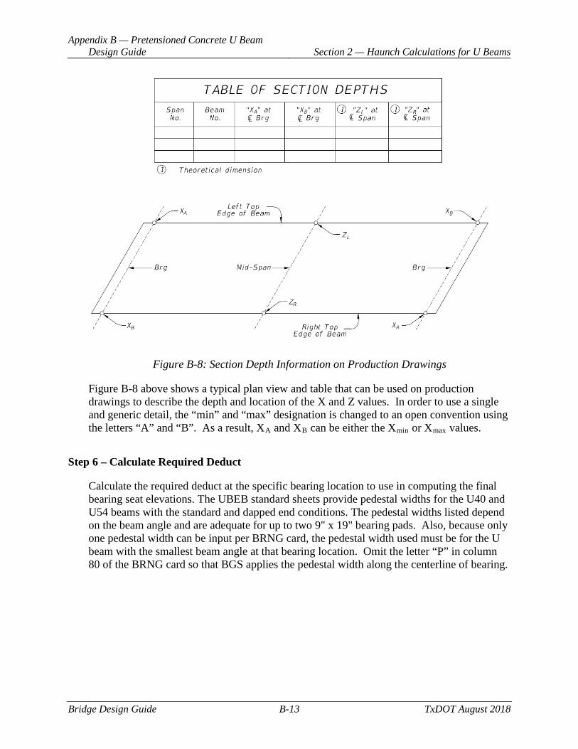
Appendix B — Pretensioned Concrete U Beam Design Guide Section 2 — Haunch Calculations for U Beams
Bridge Design Guide B-13 TxDOT August 2018
Figure B-8: Section Depth Information on Production Drawings
Figure B-8 above shows a typical plan view and table that can be used on production drawings to describe the depth and location of the X and Z values. In order to use a single and generic detail, the “min” and “max” designation is changed to an open convention using the letters “A” and “B”. As a result, XA and XB can be either the Xmin or Xmax values.
Step 6 – Calculate Required Deduct
Calculate the required deduct at the specific bearing location to use in computing the final bearing seat elevations. The UBEB standard sheets provide pedestal widths for the U40 and U54 beams with the standard and dapped end conditions. The pedestal widths listed depend on the beam angle and are adequate for up to two 9" x 19" bearing pads. Also, because only one pedestal width can be input per BRNG card, the pedestal width used must be for the U beam with the smallest beam angle at that bearing location. Omit the letter “P” in column 80 of the BRNG card so that BGS applies the pedestal width along the centerline of bearing.
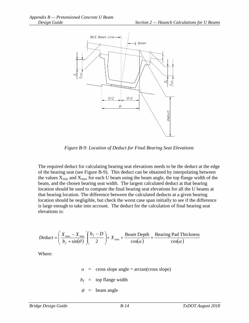
Appendix B — Pretensioned Concrete U Beam Design Guide Section 2 — Haunch Calculations for U Beams
Bridge Design Guide B-14 TxDOT August 2018
Figure B-9: Location of Deduct for Final Bearing Seat Elevations
The required deduct for calculating bearing seat elevations needs to be the deduct at the edge of the bearing seat (see Figure B-9). This deduct can be obtained by interpolating between the values Xmin and Xmax for each U beam using the beam angle, the top flange width of the beam, and the chosen bearing seat width. The largest calculated deduct at that bearing location should be used to compute the final bearing seat elevations for all the U beams at that bearing location. The difference between the calculated deducts at a given bearing location should be negligible, but check the worst case span initially to see if the difference is large enough to take into account. The deduct for the calculation of final bearing seat elevations is:
( ) ( ) ( )ααθ cosThickness PadBearing
cos DepthBeam
2sin minminmax +++
−
÷−
= XDb
bXXDeduct f
f
Where:
α = cross slope angle = arctan(cross slope)
bf = top flange width
θ = beam angle
Appendix B — Pretensioned Concrete U Beam Design Guide Section 2 — Haunch Calculations for U Beams
Bridge Design Guide B-15 TxDOT August 2018
D = bearing seat width
Note: The beam angle and cross slope can usually be ignored because of negligible difference in the final deduct amount.
Summary
The required haunch at centerline of bearing for the left and right top edges of the U beam should always be calculated working from the controlling corner for that side. This is done because the vertical clearance ordinate for the dependent corner is “built-in” to the geometry for the beam and bridge. We cannot use that value in determining our haunch because the vertical clearance ordinate at the dependent corner is always present, i.e., we cannot adjust the beam vertically to reduce that dimension. Basically, the controlling corners will have the minimum haunch at centerline of bearing, while the dependent corners will have the maximum haunch at centerline of bearing, the difference being the vertical clearance ordinate value at the dependent corner. Incidentally, because the U beam is at an average cross-slope, the haunches at centerline of bearing for the back end of the beam for the left and right edges will typically be reversed at the forward end of the beam.
At mid-span, the theoretical haunch value for the left and right top edges of each U beam will be the same value if the roadway surface cross-slope is constant or transitions at a constant rate over the entire length of the span and the beam spacing remains constant in the span. For any other case, the theoretical haunch at mid-span may be different for the left and right top edges of each U beam. Also note that, as with any beam type, the minimum haunch does not always occur at mid-span. With large crest curves and superelevation transitions, minimum haunch can occur anywhere along the beam.
Appendix B — Pretensioned Concrete U Beam Design Guide Section 3 — Beam Framing
Bridge Design Guide B-16 TxDOT August 2018
Section 3 Beam Framing
♦ Three BGS beam framing options specifically written for U-beams currently exist: Options 20, 21, & 22.
♦ When using BGS, beam spacing should be dimensioned at the bottom of beam. U-beams are not vertical but are rotated to accommodate the cross-slope of the roadway. Dimensioning the beam spacing at the bottom of the beams will allow BGS to correctly report the beam spacings on the bent reports. Also, the span sheet details should contain the note:
Beam spacing shown is measured at bottom of beam. Beam spacing at top of beam may vary due to cross-slope of U-beams.
♦ Because U-beams may not be parallel to the cross-slope of the roadway in a given span, the depth of haunch at the left and right top edge of beam may vary. Special attention should be given to these beams in calculating the haunch values.
♦ The amount of deduct for the calculation of final left and right bearing seat elevations should be the deduct at the edge of pedestal (bearing seat) on the minimum haunch side of the beam. This is where BGS applies the input deduct value for a given bearing location.
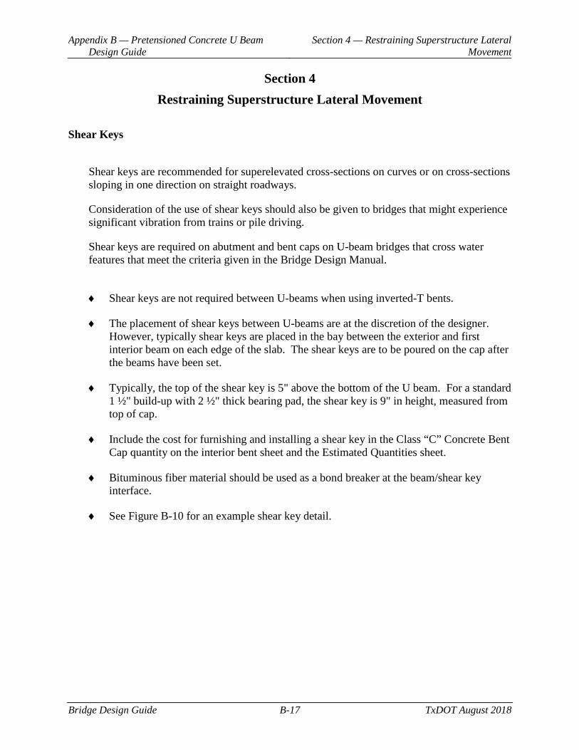
Appendix B — Pretensioned Concrete U Beam Design Guide
Section 4 — Restraining Superstructure Lateral Movement
Bridge Design Guide B-17 TxDOT August 2018
Section 4 Restraining Superstructure Lateral Movement
Shear Keys
Shear keys are recommended for superelevated cross-sections on curves or on cross-sections sloping in one direction on straight roadways.
Consideration of the use of shear keys should also be given to bridges that might experience significant vibration from trains or pile driving.
Shear keys are required on abutment and bent caps on U-beam bridges that cross water features that meet the criteria given in the Bridge Design Manual.
♦ Shear keys are not required between U-beams when using inverted-T bents.
♦ The placement of shear keys between U-beams are at the discretion of the designer. However, typically shear keys are placed in the bay between the exterior and first interior beam on each edge of the slab. The shear keys are to be poured on the cap after the beams have been set.
♦ Typically, the top of the shear key is 5" above the bottom of the U beam. For a standard 1 ½" build-up with 2 ½" thick bearing pad, the shear key is 9" in height, measured from top of cap.
♦ Include the cost for furnishing and installing a shear key in the Class “C” Concrete Bent Cap quantity on the interior bent sheet and the Estimated Quantities sheet.
♦ Bituminous fiber material should be used as a bond breaker at the beam/shear key interface.
♦ See Figure B-10 for an example shear key detail.
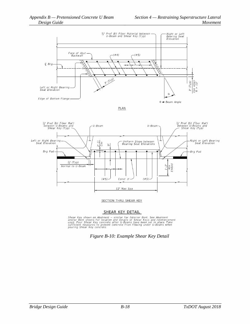
Appendix B — Pretensioned Concrete U Beam Design Guide
Section 4 — Restraining Superstructure Lateral Movement
Bridge Design Guide B-18 TxDOT August 2018
Figure B-10: Example Shear Key Detail