bridge engineering and design - 3doodler...
TRANSCRIPT

Bridge Engineering and Design Supplemental Resources
Page of 1 52
3Doodler EDU

Table of ContentsIntroduction 3
Daily Pacing Guide (Years 11 and 12) 4
Software 10
Trusses 11
Moment of Inertia 20
Beams with MDSolids 26
Beams with Solid Edge 33
Analysis with Solid Edge 42
Web Resources 52
Page of 2 52

Introduction The following pages contain additional resources for the use of commonly-available computer modeling and analysis tools in conjunction with the 3Doodler to provide a more in-depth examination of the topics covered by this unit.
Page of 3 52

Daily Pacing Guide (Years 11 and 12) Day 1 Required Materials: • Handouts:
• Project Description • Design Process • Engineering Notebook • Design Documentation
Introduce students to the main problem by providing them with the Essential Question and the Project Description.
Using the handouts found in the Resources section below, cover with your students the Design Process, Engineering Notebook and Design Documentation requirements. Discuss the Problem Statement, Design Brief, and management plan.
Have students begin thinking by means of a web search for bridge pictures.
Day 2 Required Materials: • 3Doodler 2.0: 1 for every 1 or 2 students • 3Doodler Plastic: ~3 strands per 3Doodler • Handouts:
• Shapes With 3Doodler
Begin the day with a safety demonstration about the 3Doodler and other hand tools that will be used. Discuss electrical safety with the students. Discuss the heat aspect of the 3Doodler.
Have students create the basic shapes with the 3Doodler. Provide them with the document Shapes With 3Doodler. Allow small groups to discuss which shapes withstood the pressure of a finger pressing down better than others. If they do not discuss shapes around them and why certain shapes are used, be sure to include that in the closing discussion.
Day 3 Required Materials: • Computer with Internet access • Printer • Image editing program (optional)
Why are bridges designed and constructed in many different ways?
Page of 4 52
Have students Google pedestrian bridges. Student groups select one or two bridges they like and print the picture to be used as a pattern. Have students create a pattern from the picture either by tracing or importing into a graphics program and then removing the color. Students create a simple 3Doodle model of the bridge of their choice. Have students discuss which of the models they think will be the strongest. Have students apply a simple load to the 3Doodled bridge and see how they behave.
Day 4 Required Materials: • Handouts:
• Problem Statement
Have students begin basic research about bridges. You can direct them to http://www.pbs.org/wgbh/buildingbig/bridge/ or similar site to begin to see the many different types of bridges in use. Have them record their notes in their engineering notebook
Divide the students into teams. Have the student teams discuss the Problem Statement. This will make sure they identify the problem they are trying to solve. Have them write the Problem Statement in their engineering notebook.
Day 5 Required Materials: • 3Doodler 2.0: 1 for every 1 or 2 students • 3Doodler Plastic: ~3 strands per 3Doodler • Handouts:
• Forces
Begin the day with a safety reminder.
Have students participate using the Forces document. You can save time by having a shape for the plank pre-Doodled, but deeper learning will come if they use a program like Solid Edge to draw the plank themselves. Have students make a plank to see how it behaves in tension and compression.
Day 6 Required Materials: • Windows PC or Mac w/ Windows installed • MDSolids software
Begin by reviewing the plank the students made the previous day. Have them discuss what surprised them about the material. Have them discuss other materials and why they are used. For example why is steel used in bridges? Why is concrete used for steps?
Have students discuss their thoughts on the plank they created and why it was stiffer in one direction than the other. Introduce the concept of shape to the students. Some shapes are stiffer than others. Explain that we can predict how a shape will perform, and even evaluate the performance for a specific shape and material combination.
Page of 5 52

Explain that all shapes can be evaluated as long as we know the geometry involved. To do this we need to describe the shape in relation to the Centroid which is the geometric center of the cross section of a shape. Explain that to understand shapes we will use the program MDSolids. Have them open MDSolids and find the Animated Learning Tools tab. Have them begin in the MecMovies. In the menu on the left have them expand #2 Section Properties and begins with 2.1 Centroids: Learning the Ropes. This will help them learn to estimate where the center of mass will be.
Have them record their observations in their engineering notebooks.
Day 7 Required Materials: • 3Doodler 2.0: 1 for every 1 or 2 students • 3Doodler Plastic: ~3 strands per 3Doodler
Now that students are familiar with the concept of Centroids we can now begin to look at how a shape affects the strength of a component. Have the students look a website about shapes. A site similar to http://www.pbs.org/wgbh/buildingbig/lab/shapes.html will give the students a quick understanding of shapes. Have the students create some shapes with the 3Doodler and try to predict how the shape will hold up when they press on them.
The students should also research information about deformation. One site they might look at is http://www.pbs.org/wgbh/buildingbig/lab/shapes.html.
The next concept they should explore is Ductile and Brittle materials. Have the students search for sites that explain them. One site that does a good job of explaining the concept is https://www.youtube.com/watch?v=gGXHdgsFA9s.
Have students record their observations in the engineering notebook. Have students record their observations in the engineering notebook. More detailed information is found below. https://www.youtube.com/watch?v=0s5kBrk0d80 https://www.youtube.com/watch?v=MyksI4O26G4
Day 8 Required Materials: • Windows PC or Mac w/ Windows installed • MDSolids software • Handouts:
• Moment of Inertia
Now that students have some experience with shapes introduce them to the concept of using a program to make the calculations of the strength of the shape. Introduce them to the Moment of Inertia activity. Have students print out various screen shots of their results for their engineering notebook.
Page of 6 52

Day 9 Required Materials: • 3Doodler 2.0: 1 for every 1 or 2 students • 3Doodler Plastic: ~3 strands per 3Doodler • Handouts:
• Testing Beams
Have students discuss how they might test some of the shapes they are thinking of. Introduce students to the Testing Beams activity
Day 10 Required Materials: • 3Doodler 2.0: 1 for every 1 or 2 students • 3Doodler Plastic: ~5 strands per 3Doodler • Handouts:
• Building i-Beams with 3Doodler
Begin the day asking if students are familiar with the concept of the i-beam. Talk about where they have seen them used. Have them talk about the concepts of moment of inertia and how adding mass further from the centroid creates a stiffer structure.
Have the students participate in the Building i-Beams with 3Doodler activity.
Have students discuss in their teams why the structure is more stable in this shape and what advantages it presents. Have them record their findings in the engineering notebook.
Day 11 Required Materials: • Windows PC or Mac w/ Windows installed • MDSolids software • Handouts:
• Beams with MDSolids
Review the I-Beam activity. Have students discuss issues they had with the creation of the shape. Introduce the Beams With MDSolids activity. Have students work with the software until they can predict the size and shape and the strength it will produce. Have students record their findings in their engineering notebook.
Day 12 Required Materials: • Windows PC or Mac w/ Windows installed • Solid Edge software • Handouts:
• Beams with Solid Edge
Page of 7 52

Discuss with students the results they found with the MDSolids activity. Have students work on the design of an I-beam in Solid Edge following the instructions contained in the Beams with Solid Edge handout. Explain this will help them design the shapes they will need when they design their bridge. Once they finish the design of the I beam have them select another shape and see if they can create a beam in a different shape. Have students save their beams and write predictions and comments in their engineering notebooks.
Day 13 Required Materials: • Windows PC or Mac w/ Windows installed • Solid Edge software • Handouts:
• Analysis with Solid Edge
Review the creation of beams in Solid Edge with the students. Find where they had issues and how they overcame those.
Provide students with the Analysis with Solid Edge activity. This will help them understand how the analysis tools in Solid Edge work and how they can be interpreted.
Have students record comments in the engineering notebook. Have them print out the analysis report and record a movie of how the beam behaved.
Days 14-16 Required Materials: • 3Doodler 2.0: 1 for every 1 or 2 students • 3Doodler Plastic: ~5 strands per 3Doodler • Windows PC or Mac w/ Windows installed • MDSolids software • Handouts:
• Trusses
Have the students research trusses and the various forms they take. Provide them with the Trusses handout and have them create a basic Howe Truss using the 3Doodler. Once they have a truss constructed and do some basic testing, they can move on to creating a truss in MDSolids. Students should record their progress in their engineering notebook each day noting things that gave them trouble.
Days 17-19 Required Materials: • 3Doodler 2.0: 1 for every 1 or 2 students • 3Doodler Plastic: ~5 strands per 3Doodler per day
These days are set aside for student teams to brainstorm how they want the final product to look. They work through sizing everything and then work on the scale to reduce the size to the scale model. Circulate in the room answering question and checking on students design process. Have
Page of 8 52

them record their discussions and create the design documentation they will need to present their design to the audience.
Days 20-24 Required Materials: • 3Doodler 2.0: 1 for every 1 or 2 students • 3Doodler Plastic: ~5 strands per 3Doodler per day Students should 3Doodle the pieces they will need to construct their proposed bridge and assemble. Students should check for fit and function as they go. Students can take pictures of the structure as it is built. This will allow them to discuss what was created and the process used.
Days 25-26 Required Materials: • 3Doodler 2.0: 1 for every 1 or 2 students • 3Doodler Plastic: ~5 strands per 3Doodler per day
Students design a presentation to make the case for their design of the pedestrian bridge. Students display their model while they present the thought process that went into the design.
Page of 9 52

Software MDSolids MDSolids is a great program that allows you to understand the relationship between the mechanical behavior of materials and their structures. The author, Tim Philpot has made the software and videos available to students for their use in the study of the behavior of materials and structures.
http://mdsolids.com/download/schools/ Download for educational purposes only.
http://web.mst.edu/~mecmovie/index.html Excellent videos about the analysis using MDSolids.
Solid Edge Siemens is making Solid Edge (a component of the Velocity series of PLM) available to schools at no charge. Solid Edge is technically robust, 3D CAD software and the premier design-centric solution in the CAD industry today. It allows for rapid design and testing of a digital prototype. This saves time and materials for students as they can make decisions and refine designs before construction of an actual prototype.
Schools must register for the software. Schools go to https://www.plm.automation.siemens.com/en_us/academic/resources/solid-edge/educators/highschool-download.cfm? and fill out the registration form. A license file is automatically generated and emailed to the contact listed on the application. The software is downloaded directly. The software can be installed on every computer in the school if desired and a copy provided to the students for their home computers.
Page of 10 52

Trusses To truly understand how trusses work you need to create one. The plan for this Howe truss is below.
You can print the provided stencil of the Howe truss and then use it to guide the creation of the truss.
3Doodler Pro Tip: Cover the stencil with masking tape before 3Doodling. This will make it easier to peel the truss off the page.
Once you have Doodled the components of the truss, you can apply force to them with your hands to understand how they respond to loads.
f you press down from the top you will see how strong it is in the vertical direction. Side to side it is very flexible.
Page of 11 52

Trusses are made from a series of triangles. Triangles are a shape that cannot change without lengthening one side. When forces are applied to a truss some of the members (called webs) act in compression and some act in tension. These forces balance each other and the shape is maintained. This is why the truss is so rigid when a force is applied from the top — the webs balance the force that is being applied to the truss.
You will notice all the webs that make up the truss are the same size. As a practical matter, this is convenient if you want to use only one size of material. On real bridges you will see all different sizes of materials used.
If you think about the material and when you held a plank in your fingers and pushed the ends together causing compression the component buckled easily. When you tried to pull the ends placing it in tension it was very resistant to tension.
If you can examine the truss you want to build you can put more material in the components that will be in compression to help withstand the stress. Your tension members can take advantage of the properties of the material and be made lighter.
Page of 12 52

The mathematical analysis of the truss can tell us which webs are in tension and which are in compression. Using Computer Aided Engineering software allows for us to very easily see where the forces are.
From the main menu of MDSolids select the option for trusses.
Select the option for a new truss.
You will then get a dialog box for the sizing of the spacing. Since we used 13 mm on the truss design we will set the spacing intervals to that. Set the number of spaces to 10 on the horizontal and to 6 on the vertical. This will keep the squares on the screen fairly even.
Set the program to create members of the truss by clicking the radio button next to create and the one next to members. Start at an intersection of the grid. Left click on the intersection and then hold the mouse button down while you pull off the intersection to the next location you want. You will see a black line following your mouse. When you are over the next intersection let go of the mouse button.
Page of 13 52

Once you let go the program will begin calculating. Remember that it needs triangles to perform the calculations.
Continue placing all the parts of the truss. Remember that all the lines go from one grid intersection to the next and should show you the node points.
If you make a mistake you can remove a line by selecting the erase option and use the same method as before. Select the intersection, left click and hold and let go at the other end of the incorrect line and it will go away.
Once you have the structure assembled we will need to provide supports so the program knows where to transfer all the loads. We will place the supports at either end.
Page of 14 52

To do this select Create and also Supports. Click on the intersection and drag the mouse off the intersection. In the picture below the direction was in the Y or downward direction. Do not let go of the mouse button until you are past the end of the black line.
This will create a support under that component of the truss. In this case it is a rolling support.
To make this a fixed support you will repeat the process dragging in the X direction.
Page of 15 52

This will create the fixed support at the end of the truss.
At the other end we only need to support the truss in the Y direction. Click on the other end and drag downward.
This will create the other roller support. Notice that the first support has changed orientation to match.
Page of 16 52

At the other end we only need to support the truss in the Y direction. Click on the other end and drag downward.
This will create the other roller support. Notice that the first support has changed orientation to match.
This will bring up a dialog box which will ask for the load you wish to apply.
Once your magnitude is set you select Enter Load.
You will see the magnitude line appear with the magnitude listed. You will also note that the compute button is now active.
Page of 17 52
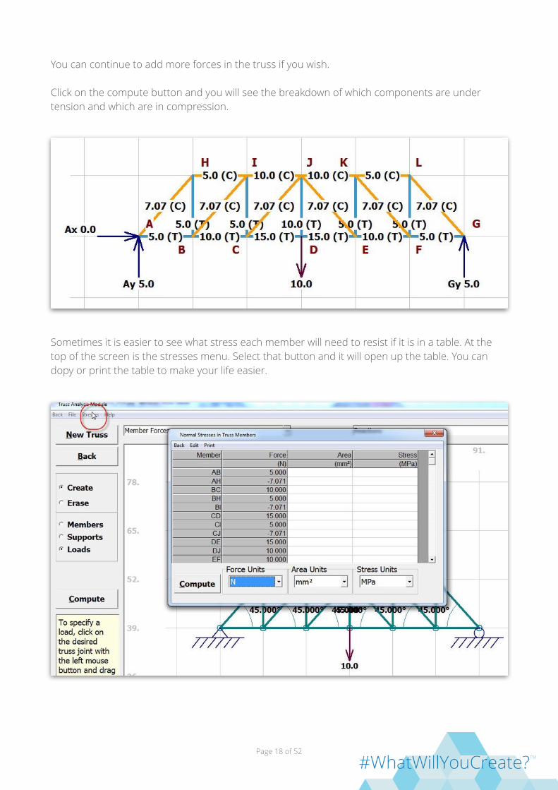
You can continue to add more forces in the truss if you wish.
Click on the compute button and you will see the breakdown of which components are under tension and which are in compression.
Sometimes it is easier to see what stress each member will need to resist if it is in a table. At the top of the screen is the stresses menu. Select that button and it will open up the table. You can dopy or print the table to make your life easier.
Page of 18 52

A simulation can also be done in Solid Edge to see how the truss will perform there once you adjust the shapes you want. If you want to see it accurately you will need to select the Actual deformation setting.
Page of 19 52

Moment of Inertia Moments are a twisting force applied to a reference point. Multiply the force applied by the distance from the point to give you an idea of the twisting force. When we need to design a shape to withstand the forces applied we need to have an idea of the moments that are applied. Before undertaking this exercise be sure you understand the concept of Centroids. A good activity is the Centroids game in MDSolids.
Once you understand the concept of centroids you can then begin to explore the concept of strength of a shape. The strength of the shape can be defined as its resistance to deflecting in the direction of applied force. In the 3Doodler exercise you created a plank and pushed down on it. You discovered that rotating it 90 degrees to align the long axis with the force greatly increased the resistance to bending. Engineers pay attention to this concept and have a way of predicting what the effects will be.
We call the concept second moment of area or moment of inertia. Mathematically it is the area of the plane of the object if it were sliced multiplied by the square of the distance from the axis. This will give us a number in mm4 or in4. We can compare different shapes with this number. You have already experienced this in your testing of the plank. We can use a computer aided engineering program to show you the results.
Open MDSolids and select the option for Section Properties.
Page of 20 52

This will bring up the section properties module. Select Simple from the menu.
From the options select rectangle. This will allow you to duplicate the testing of the plank.
On the screen you will enter in the information from our plank. Set the units to mm. Enter in the 13mm from the width of the plank. Enter in 1 as the thickness. This is the orientation of the plank when it is on edge. The rest of the information will be used in the future but we can ignore it for the moment.
Page of 21 52
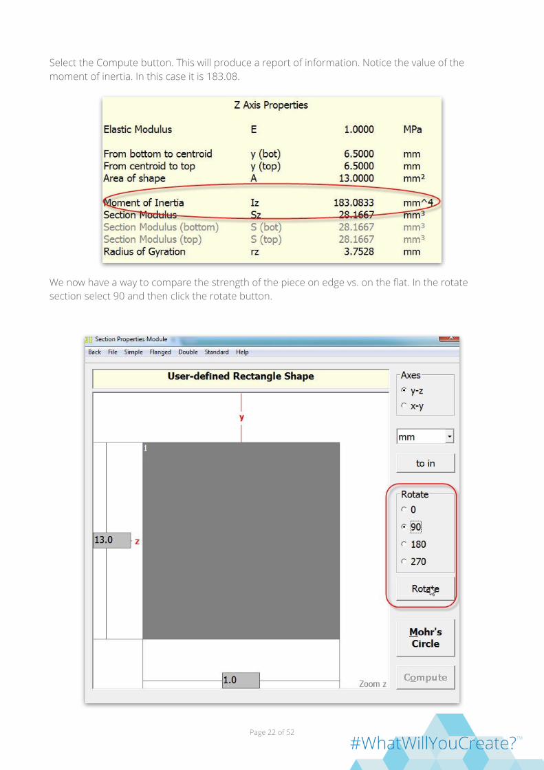
Select the Compute button. This will produce a report of information. Notice the value of the moment of inertia. In this case it is 183.08.
We now have a way to compare the strength of the piece on edge vs. on the flat. In the rotate section select 90 and then click the rotate button.
Page of 22 52

Once you rotate the object you will see the dimensions have switched places and the compute button is active once again. Select the compute button again and get a report for this section.
Notice the moment of Inertia.
Double the thickness of the plank. The setup is similar to the one shown below. Before you hit the calculate button make a prediction as to what you think the moment of inertia will be. Once you make your prediction click the compute button.
Page of 23 52

You can see doubling the height had a large impact on the change in Moment of Inertia.
The Moment of Inertia changed from 1.0833 to 8.6667. Now think about this piece on the edge. Rotate the beam again so the 13 mm is the height again.
Page of 24 52

Once you recalculate you will find the Moment of Inertia doubled by doubling the width, whereas doubling the height was a geometric increase.
Try some different shapes to see how the moment of inertia stands up.
Page of 25 52

Beams with MDSolids When designing structures we can use standard components or we can custom make the shapes in our own design. MDSolids can be used to provide us with details about the strength of shapes we are thinking of using. The ability to predict how a shape will perform before spending the time and money creating the shapes is critical to the design process. Computer aided engineering programs make this possible.
Before you can begin designing you will need to understand how shape affects the strength of what we design. Thousands of years ago people built pyramids. Pyramids were mostly solid objects with small rooms and hallways in them. A few thousand years later people built stone walls and laid wood beams across the openings to make floors. These floors were mostly solid. Besides being a waste of materials the use of solid components meant that the rest of the structure had to be of heavier construction to carry the weight. Today’s designers utilize shaped structures to reduce weight and still keep the same strength.This has allowed us to build taller buildings, airplanes and bridges that we were not able to in centuries past.
Page of 26 52
These activities will help you understand how shapes can be selected for certain applications and performance predicted. When we create a structure we need to know how much it will deflect under load. Loads are the forces acting on structures. There are three basic categories of loads. Dead loads are loads that are fairly constant over time. They include the weight of the structure and immovable fixtures. Live loads are loads that are constantly changing. In the picture above you can see the live load on the bridge. Live loads also include wind, snow, vehicles and other temporary loads. As it is impossible to be accurate in the estimation of what the live load will be engineers use a per square foot estimation when designing. There is always a factor of safety in designs in case the load is much larger than anticipated. The structure is always overbuild just in case. The last load to consider is impact loading. There have been many instances of barges hitting bridges, vehicle crashes and other sudden applications of force. Designers always add extra strength in all directions just in case.
To begin designing you need an idea of how we can utilize shapes to our advantage. You constructed a simple I-beam and found out how strong the shape is. Engineers utilize software to compare elements to select the ones they want. Lets look at the I-beam you constructed.
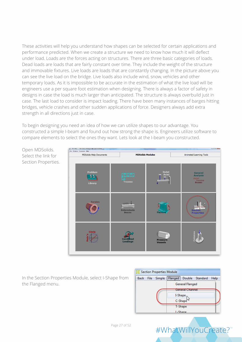
Open MDSolids. Select the link for Section Properties.
In the Section Properties Module, select I-Shape from the Flanged menu.
Page of 27 52

In the window for the user defined I shape enter the following information about the I-beam.
Notice that we included an elastic modulus of 1.4 GPa. This is a measurement of the strength of the material. Testing has established how the material deforms when stress is applied. We know that the 3Doodler uses ABS plastic (among a number of other materials) so we looked up ABS properties at the site www.matweb.com. You will find over a hundred different types of ABS. Their elastic modulus vary from 1.4 to 4.3 GPa. This is on a consistent sample and ours is layered so we will not be as strong as a solid piece. This is why we are using 1.4 GPa
Click on the Compute button. Notice how much the Moment of Inertia is when the material is in the I shape. If we had three planks set side by side it would be much less.
Now that the program knows what the shape and material is we can ask it about the I-beam. Specifically we want to know how much it will deflect when we put a load on the beam. At the top left hand corner of the Section Properties Module you will find a back button. Click that button to return to the main menu.
Page of 28 52

From the main menu select the Determinate Beams.
This will bring up the Determinate Beam Module. Click on the left hand option where the beam will be supported at two points.
Enter the information about our beam. Once you are done select Enter.
Page of 29 52
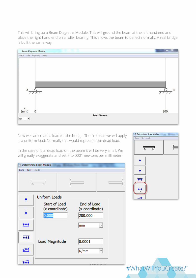
This will bring up a Beam Diagrams Module. This will ground the beam at the left hand end and place the right hand end on a roller bearing. This allows the beam to deflect normally. A real bridge is built the same way.
Now we can create a load for the bridge. The first load we will apply is a uniform load. Normally this would represent the dead load.
In the case of our dead load on the beam it will be very small. We will greatly exaggerate and set it to 0001 newtons per millimeter.
Page of 30 52

When you are ready select the Enter button. This creates some graphs for you. The default graphs are shear and moments. We will want to see the deflection so we will select options on the Beam Diagrams Module.
Once the next set of graphs comes up we will look at the bottom graph. This is showing us a deflection of .001 mm from the weight of the beam.
Now we will add the force pushing down with our finger. On the module select a concentrated load with a force in the downward direction. This will be centered on the beam, about half way which would be 100 mm. I used a 20 N load.
Page of 31 52

This is added to our existing forces. Select the enter button again
Now when we look at the prediction a 20 newton force will cause the beam to deflect almost 1.8 mm.
This is a lot more deflection that would be allowed for a bridge. Normally we aim for the live load to cause a deflection less than the length of the beam divided by 360 to allow for the live load. This would be about .55 mm. So if we wanted to be sure our I-beam would support the load we would need to go back to the section properties box by using the back buttons
This will take you to the main menu. Select the Section Properties. You will select the flanged option again and then the I Shape. You will see your original information there. Modify the information to see if you can resist the changes. In the example below I have changed my height of the central web to 18 mm. Select compute again. Once you receive the report you can use the back button to return to the main menu and then to the determinate beams. You will see a new button labeled Refresh Beam Diagrams.
Click on this and then find the deflection diagram again.
On rechecking I can see I am deflecting less than a mm but still not as small a deflection as I wanted. In this way I can go back and forth adjusting the sizes of the design to arrive at what is needed to carry the load.
Page of 32 52
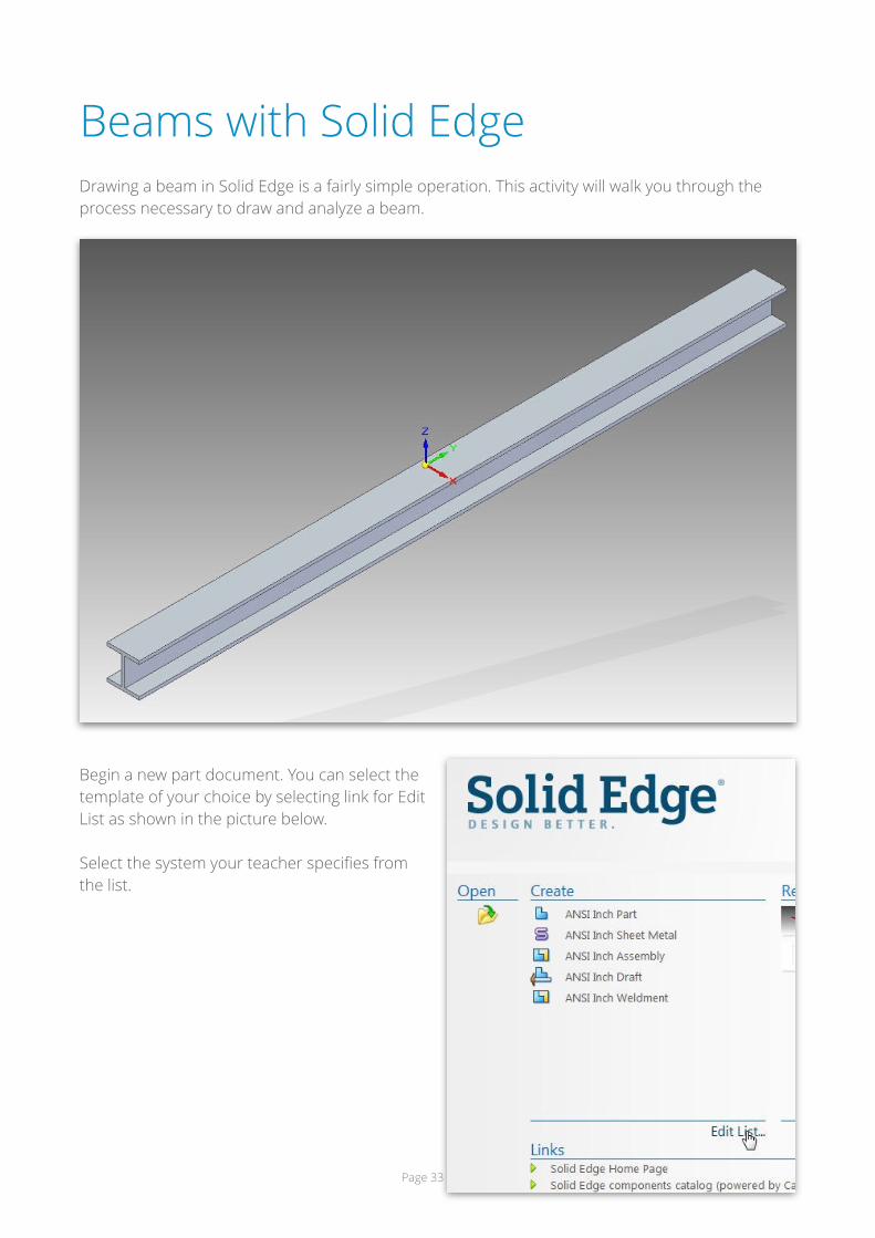
Beams with Solid Edge Drawing a beam in Solid Edge is a fairly simple operation. This activity will walk you through the process necessary to draw and analyze a beam.
Begin a new part document. You can select the template of your choice by selecting link for Edit List as shown in the picture below.
Select the system your teacher specifies from the list.
Page of 33 52

From the list of possible choices from the specified system select the Part.par option to place the choice on the list. Select Apply. Select OK to place the selection as the default system.
Select the Part option. In the picture below the ANSI Metric Part is selected. This will open up a new part file.
Once the part file opens select the view control in the bottom right had corner of the screen. Click on the front to center the view.
Now select the Sketching ribbon at the top of the screen to bring up the sketching tools.
Page of 34 52

Select the line command from the Sketching ribbon.
As you draw your “I” shape it doesn’t have to be totally accurate but if you get it close it will be much easier to complete the shape to analyze. Begin by clicking on the screen and then moving your mouse to the right. In this instance I want a line about 10 mm in length. After the shape is identified I will constrain the shape so it is accurate. If your scale is incorrect you can zoom in and out using the wheel in the middle of your mouse.
The software is intuitive. Because I am moving at a right angle it locks in at -90 degrees. I want a top web thickness of about 1 mm. Again don’t worry if it is not quite exact yet.
Page of 35 52
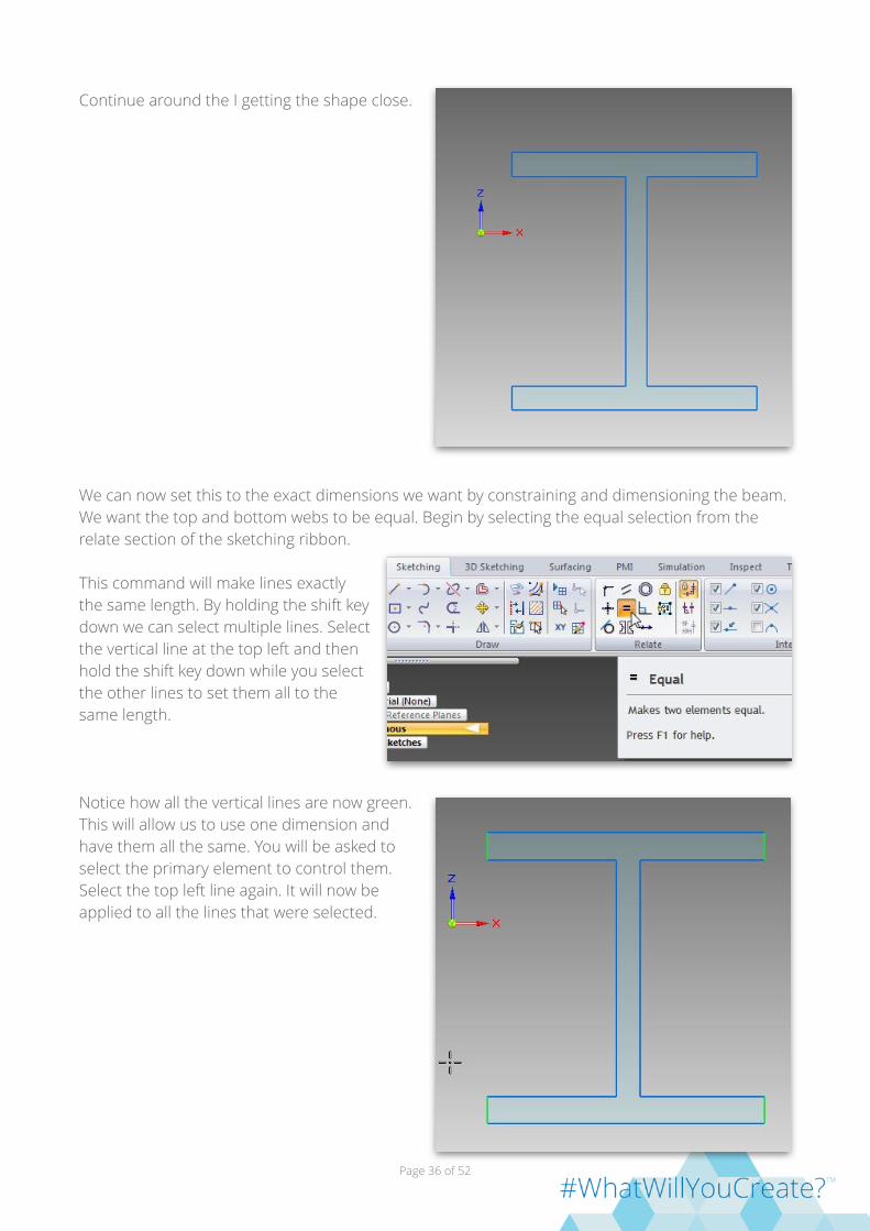
Continue around the I getting the shape close.
We can now set this to the exact dimensions we want by constraining and dimensioning the beam. We want the top and bottom webs to be equal. Begin by selecting the equal selection from the relate section of the sketching ribbon.
This command will make lines exactly the same length. By holding the shift key down we can select multiple lines. Select the vertical line at the top left and then hold the shift key down while you select the other lines to set them all to the same length.
Notice how all the vertical lines are now green. This will allow us to use one dimension and have them all the same. You will be asked to select the primary element to control them. Select the top left line again. It will now be applied to all the lines that were selected.
Page of 36 52
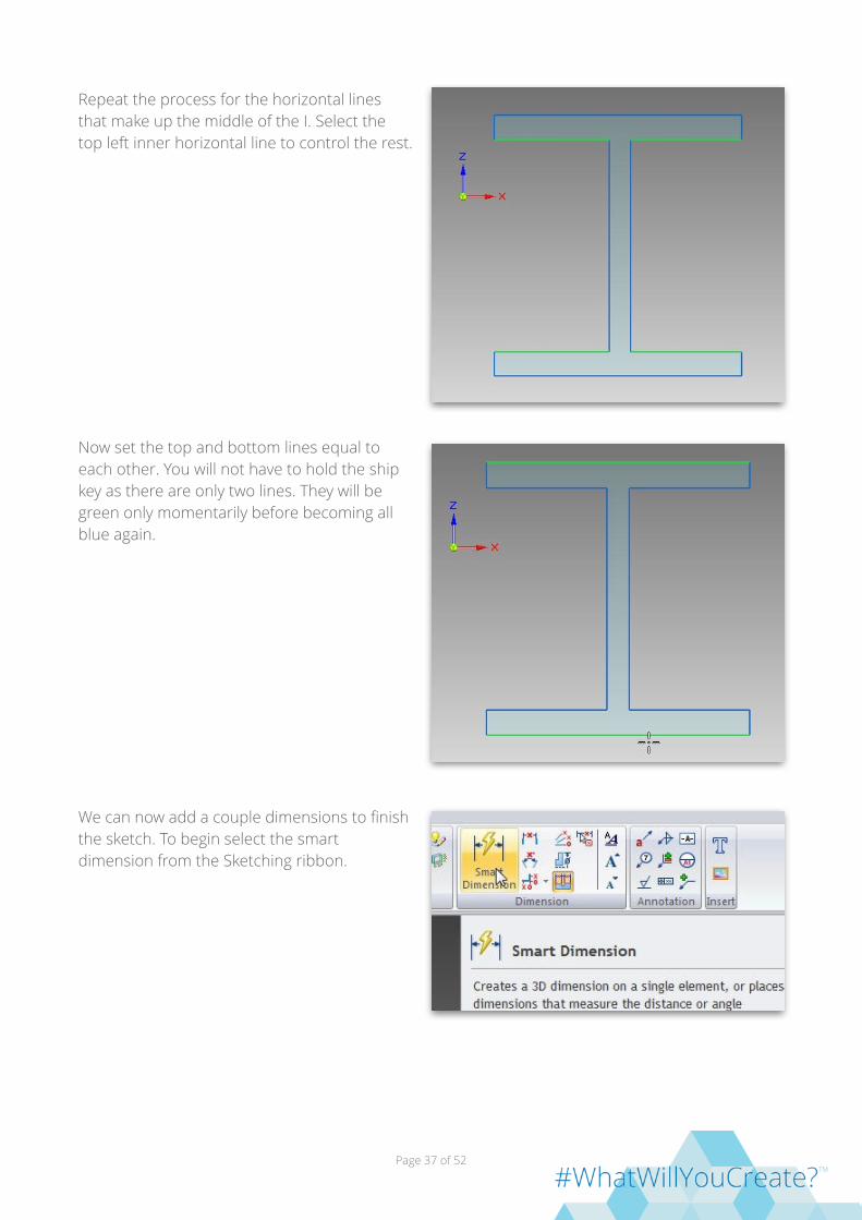
Repeat the process for the horizontal lines that make up the middle of the I. Select the top left inner horizontal line to control the rest.
Now set the top and bottom lines equal to each other. You will not have to hold the ship key as there are only two lines. They will be green only momentarily before becoming all blue again.
We can now add a couple dimensions to finish the sketch. To begin select the smart dimension from the Sketching ribbon.
Page of 37 52

Select the top vertical line on the left that we used as the primary element. After you click on the line pull off to the left and you will see the dimension travel with the mouse.
Left click again to place the dimension. The dialog box will open and you can set the dimension to the desired size. In this case 1 mm is used.
Hit your enter key and the dimension will change and the rest of the lines you established as equal will now be 1mm. Add two more dimensions to complete sizing the beginnings of your I beam. If you correctly applied the equal relationships it should be consistent with all elements being 1mm thick.
Set the view into an isometric view by selecting the Home on the view control at the bottom right hand corner of the screen.
Page of 38 52

The view should now look similar to the picture below.
We are now ready to extrude the beam to the desired length. In this case the beam will be set to 200 mm. Select the Home section of the Ribbon and then select Extrude as the desired option.
Page of 39 52

Slide the mouse over the “I” that you created. It will highlight.
Left click on the I to select it. It will change color to let you know it has been selected.
Page of 40 52

Right click to finish selecting. As you move your mouse you will see the beam begin the extrusion process. Type 200 on your keyboard and the program set the length of the I beam to 200.
Your beam should now appear as the one pictured below.
If you want to hide the dimensions so they are no longer visible right click on each one and select hide. We are now ready to simulate the testing of the beam. Save your file to be sure it is safe.
Page of 41 52

Analysis with Solid Edge The Analysis function in Solid Edge allows us to simulate loading conditions on the model and determine its behavior or response at different locations. This information allows us to determine how our model will actually perform before we spend the time and material to create the actual structure. To perform the analysis certain parameters must be set and the process understood.
Finite element analysis predicts behavior by braking the solid model into small elements. If you think of the beam as made up from hundreds of mini-marshmallows you can see that each marshmallow is one element of the entire structure. As we load the structure each marshmallow interacts with the one next to it so the behavior is easy to see. To perform the analysis on the beam we will need to define how many elements we will divide the structure into. This is done with something called a mesh. This will allow a focused look at each element and how they all interact. The program will automatically perform the numerical approximation to create the solution based on the solid model boundaries. It is also important to provide the material so the analysis will understand how it will behave. We can then export a report of the analysis so we can see visually how our design will perform under conditions we are likely to see.
Process
Open the beam you designed in the beam design activity.
Select the Simulation section of the ribbon. When it appears, select New Study to begin the analysis setup.
Page of 42 52
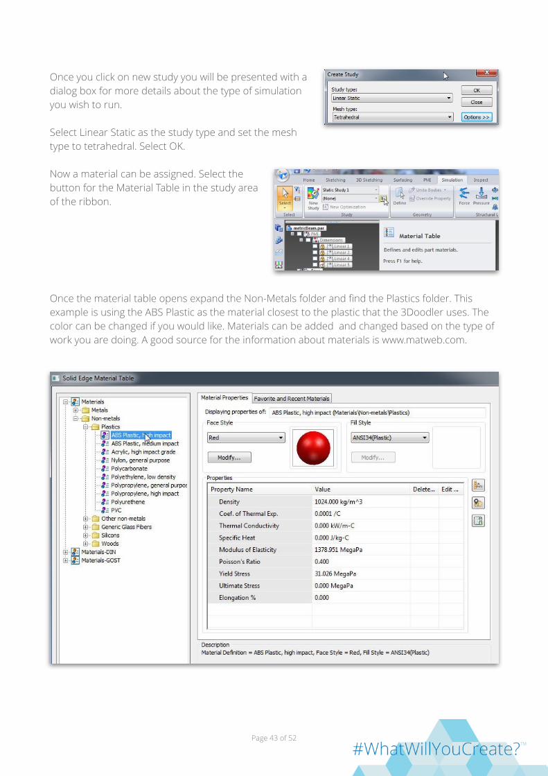
Once you click on new study you will be presented with a dialog box for more details about the type of simulation you wish to run.
Select Linear Static as the study type and set the mesh type to tetrahedral. Select OK.
Now a material can be assigned. Select the button for the Material Table in the study area of the ribbon.
Once the material table opens expand the Non-Metals folder and find the Plastics folder. This example is using the ABS Plastic as the material closest to the plastic that the 3Doodler uses. The color can be changed if you would like. Materials can be added and changed based on the type of work you are doing. A good source for the information about materials is www.matweb.com.
Page of 43 52

When you have things the way you want select the “apply to model” button at the bottom of the dialog box.
You will see the color you selected applied to your model. The color makes us feel good but the parameters such as the modulus of elasticity will tell the program how the model should behave.
Now that the material has been applied we can set the mesh. If the mesh is too fine it will take a long time to solve. If the mesh is too large the computer will not be able to figure out how the structure will behave.
Select the Mesh icon from the Mesh section of the Ribbon.
This will open the Tetrahedral Mesh dialog box. Begin by checking the box for Show mesh on close.
Page of 44 52
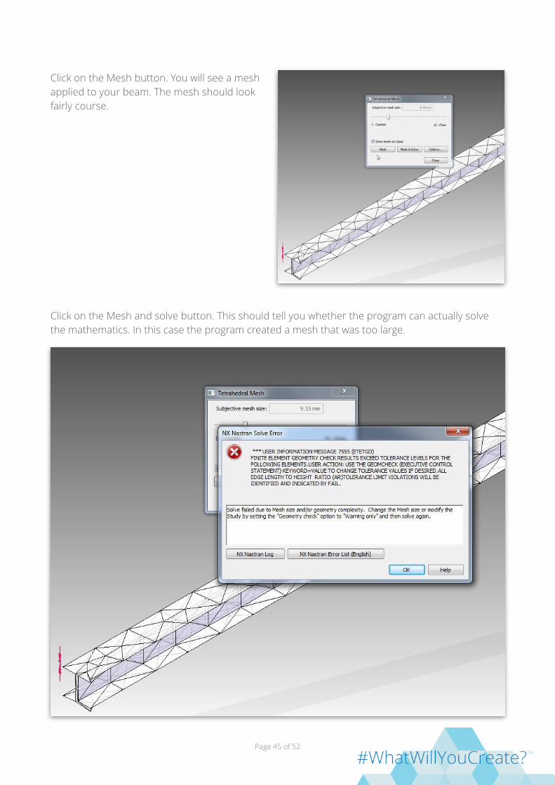
Click on the Mesh button. You will see a mesh applied to your beam. The mesh should look fairly course.
Click on the Mesh and solve button. This should tell you whether the program can actually solve the mathematics. In this case the program created a mesh that was too large.
Page of 45 52

Since the error is about mesh size we can make the mesh smaller with the slider. Dismiss the error message and move the slider to make the mesh smaller.
When you click on mesh this time the mesh will be much smaller. Select Close.
In order for the computer to solve the analysis we need to add some constraints. In the constraints section of the ribbon select the Icon for Fixed.
Now select the end of your beam. Wait until it highlights so you are selecting the end plane.
Page of 46 52

Left click to select the end and then right click to fix the end. You will see a ball appear to let you know it is fixed.
To truly see how this beam will behave we will need to pin the opposite end to allow it to be stationary but still allow the beam to move. Rotate the beam around so you are looking at the opposite end. Select the Pinned Icon from the constraints menu.
Make sure you are selecting just the end. Left click to select and then right click to accept the end.
Page of 47 52
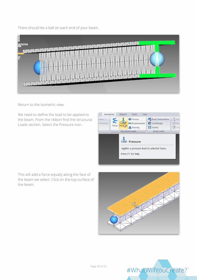
There should be a ball on each end of your beam.
Return to the isometric view.
We need to define the load to be applied to the beam. From the ribbon find the structural Loads section. Select the Pressure icon.
This will add a force equally along the face of the beam we select. Click on the top surface of the beam.
Page of 48 52

You will see the force arrows appear. This example utilizes a force of 17 kPa in a downward direction.
If the arrows are pointing up they can be reversed by selecting the flip direction arrows on the tool bar or typing F to flip the direction. Right click to accept the setting.
We can now try to solve the analysis of the beam. Select the solve button on the Ribbon.
Page of 49 52
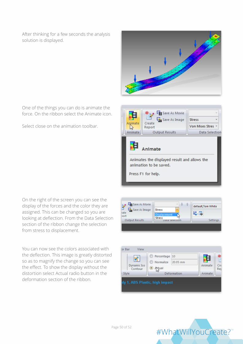
After thinking for a few seconds the analysis solution is displayed.
One of the things you can do is animate the force. On the ribbon select the Animate icon.
Select close on the animation toolbar.
On the right of the screen you can see the display of the forces and the color they are assigned. This can be changed so you are looking at deflection. From the Data Selection section of the ribbon change the selection from stress to displacement.
You can now see the colors associated with the deflection. This image is greatly distorted so as to magnify the change so you can see the effect. To show the display without the distortion select Actual radio button in the deformation section of the ribbon.
Page of 50 52

You will see the effect immediately. Now the display is showing the displacement in proportion to the object.
The animation movies can be saved to be played during a report. You can also print out the entire report of the simulation results. These options are all found in the output results of the ribbon.
Page of 51 52

Web Resources http://www.mdsolids.com/truss.htm MDSolids truss analysis introduction
https://www.youtube.com/watch?v=Pv_MLSU5exA Truss setup for MDSolids video
https://www.youtube.com/watch?v=ZXZBruRkUp8 Truss Analysis with MDSolids video
Page of 52 52