bridge lab manual winter 2012-2013
DESCRIPTION
Drexel MEM 331 Lab SolutionTRANSCRIPT

1
MEM 331 – Truss Structures Lab
Department of Mechanical Engineering and Mechanics
Drexel University

2
TRUSS STRUCTURE EXPERIMENT EXPERIMENTAL DETERMINATION OF THE FORCES ACTING ON TRUSS STRUCTURE
MEMBERS UNDER LOAD
I: INTRODUCTION AND OBJECTIVES A truss is a structural element composed of a stable arrangement of slender interconnected bars (see Figure 1). The pattern of bars, which often subdivides the truss into triangular areas, is selected to produce an efficient, lightweight, load-‐bearing member. Although joints typically formed by welding or bolting truss bars to gusset plates, are rigid, the designer normally assumes that members are connected at joints by frictionless pins. Since no moment can be transferred through a frictionless pin joint, truss members are assumed to carry only axial force; either tension or compression. Because truss members act in direct stress, they carry load efficiently and often have relatively small cross sections.
As shown in Figure 1, the upper and lower members, which are either horizontal or sloping, are called the top and bottom chords. The chords are connected by vertical and diagonal members. The structural action of many trusses is similar to that of a beam. As a matter of fact, a truss can often be viewed as a beam in which excess material has been removed to reduce weight. The chords of a truss correspond to the flanges of a beam. The forces that develop in these members make up the internal couple that carries the moment produced by the applied loads. The primary function of the vertical and diagonal members is to transfer vertical force (shear) to the supports at the ends of the truss.
Generally, on a per pound basis it costs more to fabricate a truss than to roll a steel beam; however, the truss will require less material because the material is used more efficiently. In a long-‐span structure, say 200 ft or more, the weight of the structure can represent the major portion (on the order of 75 to 85 percent) of the design load to be carried by the structure. By using a truss instead of a beam, the engineer can often design a lighter, stiffer structure at a reduced cost. Even when spans are short, shallow trusses called bar joists are often used as substitutes for beams when loads are relatively light.
The diagonals of a truss typically slope upward at an angle that ranges from 45 to 60°. In a long-‐span truss the distance between panel points should not exceed 15 to 20 ft (5 to 7 m) to limit the unsupported length of the compression chords, which must be designed as columns. As the slenderness of a compression chord increases, it becomes more susceptible to buckling. The slenderness of tension members must be limited also to reduce vibrations produced by wind and live load.
If a truss carries equal or nearly equal loads at all panel points, the direction in which the diagonals slope will determine if they carry tension or compression forces. Figure 4.3, for example, shows the difference in forces set up in the diagonals of two trusses that are identical in all respects (same span, same loads, and so forth) except for the direction in which the diagonals slope (T represents tension and C indicates compression).

3
Figure 1: Example truss structure with load cells mounted (not the exact structure you will build)
II: BACKGROUND AND THEORY
ANALYSIS OF TRUSSES A truss is completely analyzed when the magnitude and sense (tension or compression) of all bar forces and reactions are determined. To compute reactions of a determinate truss, we treat the entire structure as a rigid body and, as discussed in Section 3.6, apply the equations of static equilibrium together with any condition equations that may exist. The analysis used to evaluate the bar forces is based on the following three assumptions:
1. Bars are straight and carry only axial load (i.e., bar forces are directed along the longitudinal axis of truss members). This assumption also implies that we have neglected the deadweight of the bar. If the weight of the bar is significant, we can approximate its effect by applying one-‐half of the bar weight as a concentrated load to the joints at each end of the bar.
2. Members are connected to joints by frictionless pins. That is, no moments can be transferred between the end of a bar and the joint to which it connects. If joints are rigid and members stiff, the structure should be analyzed as a rigid frame.
3. Loads are applied only at joints. As a sign convention (after the sense of a bar force is established) we label a tensile force positive and a compression force negative.
Bar forces may be analyzed by considering the equilibrium of a joint—the method of joints—or by considering the equilibrium of a section of a truss—the method of sections.
The method of joints is based on the conclusion that for a truss to be in equilibrium, each of the joints must be in equilibrium. This means that at a joint, the sum of the forces in the vertical direction must be equal to zero and the sum of the forces in the horizontal direction must be equal to zero. Since the analysis is already based on assumption 2, the sum of the moments need not be considered. To solve the truss using methods of joints, write the equilibrium equations in both directions for all the joints. Arrange all the equations in a system of simultaneous equations and solve the system for the forces in each member.
The method of sections is another method to determine forces in members of a truss structure. In order to find unknown forces in using the method of sections, sections of the truss structure must be isolated. The net force on the entire isolated section must be zero since the isolated section does not move (if it did move it wouldn't be a statics problem). This method is often faster because

4
instead of moving from joint to joint with the method of joints, the members of interest can be immediately isolated.
III: EXPERIMENTAL PROCEDURE
EQUIPMENT LIST: Part Description
Quantity
A. #5 Beams 12 B. #4 Beams 6 C. #3 Beams 5 D. #2 Beams 4 E. #1 Beams 2 F. Brackets 14 G. Screws 50 Load Cells 5 Weights (200g) 2
Constructing the Bridge Construct the Warren truss bridge as shown in figure 2 and table 1.
Note that segments AB, BC, BD, CD and CE contain load cells. For these members, screws are inserted through the beams into the load cell in order to join the beams of which said members are comprised.
Table 1: Beam code for each member of the Truss Bridge.
Segment Beam B'D' #5 (24cm) C'D' #4 B'C' #4 C'E' #5

5
E'G', EG #5 D'F', DF #5 D'E', DE #4 E'F', EF #4 F'G', FG #3 B'B, #5 C'C #5 D'D #5 E'E #5 F'F #5 G'G #5 BC 2x#2 CD 2x#2 BD 2x#3 CE 2x#3 A'B' 2x#1 AB #3
Figure 2.a: Front face of truss bridge
Figure 2.b: Back face of truss bridge
A
B
C
D
E
F
G
A
B
C
D
E
F
G

6
Figure 2.c: Top view of truss bridge
Measuring Static Load a. Hang one 200g load at B and another 200g load at B’. Loosen all the screws in the structure
so the members are resting on their pins. This will eliminate any extra moments due to the screws. Record the forces in members AB, BC, BD, CD and CE using Data Studio. Be sure to hit the Tare button at the beginning of each data collection to zero out the weight of the truss and its components.
b. Repeat this procedure for loads hung at C and C’, D and D’ and F and F’.
DATA ANALYSIS AND DISCUSSION 1. Compare results obtained in steps 2.a and 2.b in the procedure to theoretical results
obtained from using the method of joints for this structure. Take the length of the beams with the load cells to be equal to the #5 beams (24cm).
2. Comment on the effect of location of the location of the applied load on the state of axial loading in members AB, BC, BD, CD and CE.
3. Determine a location at which the load can be applied in order to generate i. Zero axial load in Member BC ii. Zero axial load in Member BD
4. Based on the fact that loads are symmetrically applied (equal load simultaneously applied to B and B’ for example) guess the axial load in members BB’, CC’, DD’, EE’, FF’, GG’ and HH’.
REFERENCES 1. http://highered.mcgraw-‐hill.com/sites/dl/free/0073132950/388142/Chapter4.pdf 2. Pasco Instruction Manual 012-‐10656A
B C
B’ C’
D
D’
E
E’
F
F’
7
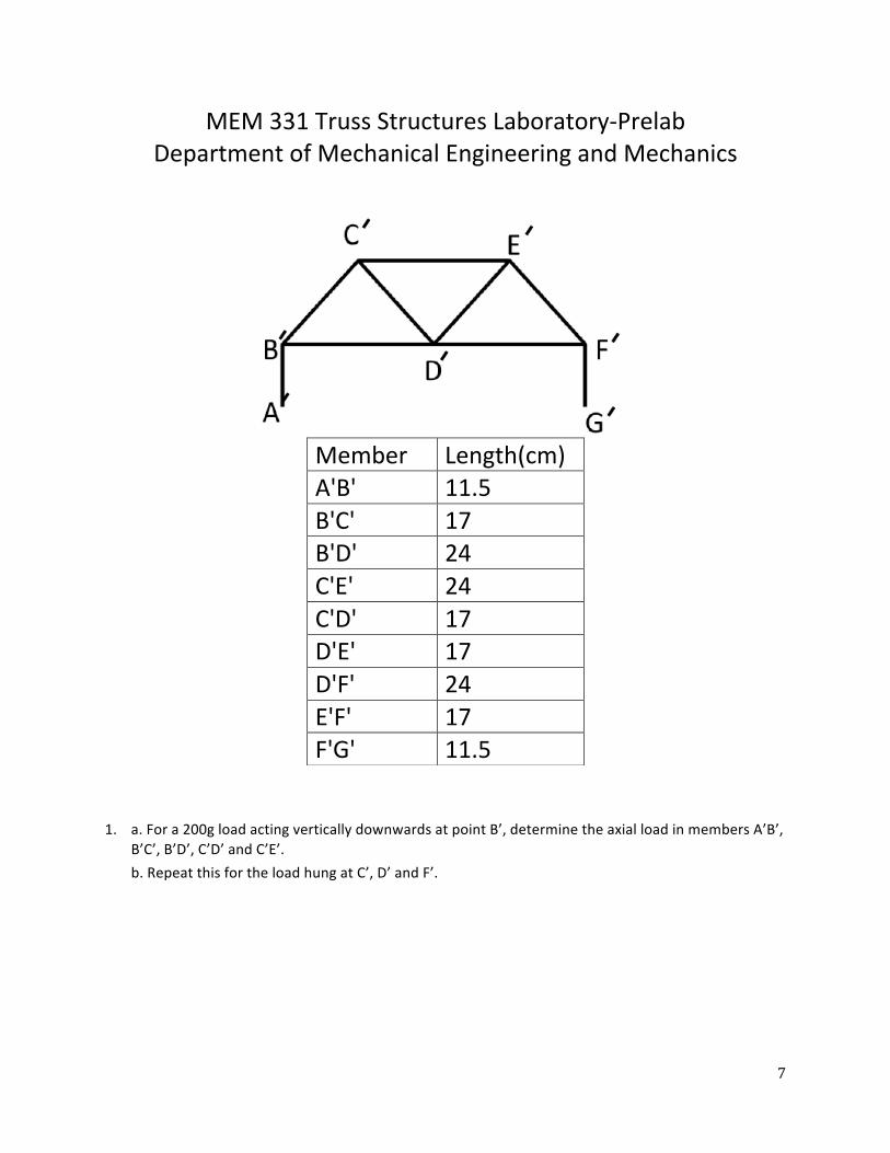
MEM 331 Truss Structures Laboratory-‐Prelab Department of Mechanical Engineering and Mechanics
1. a. For a 200g load acting vertically downwards at point B’, determine the axial load in members A’B’, B’C’, B’D’, C’D’ and C’E’. b. Repeat this for the load hung at C’, D’ and F’.
Member Length(cm) A'B' 11.5 B'C' 17 B'D' 24 C'E' 24 C'D' 17 D'E' 17 D'F' 24 E'F' 17 F'G' 11.5