bridge standards and procedures manual volume 2
TRANSCRIPT


Procedures and Directions
Volume 2 Table of Contents
August 2007 -i- Revision 1
1 General .................................................................................................................................. 1 1.1 Scope .............................................................................................................................. 1 1.2 Software .......................................................................................................................... 1 1.3 Paper Space/Model Space in AutoCAD .......................................................................... 1 1.4 Numbering of Drawings ................................................................................................... 1 1.5 Drawing Size ................................................................................................................... 2 1.6 Standard Ministry Border Sheets for Bridges .................................................................. 2 1.7 Signing of Drawings ........................................................................................................ 5
2 Drawing Preparation .............................................................................................................. 7 2.1 Standard AutoCAD Template .......................................................................................... 7 2.2 Layering and Line Types ................................................................................................. 7 2.2.1 Layering ........................................................................................................................... 8 2.2.2 Line Types ....................................................................................................................... 9 2.3 Colour Assignments and Plot Parameters .................................................................... 10 2.4 Text Styles and Heights ................................................................................................ 11 2.4.1 Standard Text Heights ................................................................................................... 11 2.4.2 Standard Text Codes .................................................................................................... 12 2.5 Dimensioning ................................................................................................................. 14 2.6 Drawing Units and Scales ............................................................................................. 16 2.7 Work Points ................................................................................................................... 17 2.8 AutoCAD Standard Symbols Library ............................................................................. 17 2.9 Section and Detail References ...................................................................................... 19 2.10 Road Geometry ............................................................................................................. 19
3 Drawing Standards .............................................................................................................. 20 3.1 Preliminary Drawings .................................................................................................... 20 3.2 Contract Drawings ......................................................................................................... 21 3.3 Drawing Layout ............................................................................................................. 22 3.4 Cover Sheet .................................................................................................................. 23 3.5 General Notes and Drawing List ................................................................................... 23 3.6 Site Plan ........................................................................................................................ 23 3.7 General Arrangement .................................................................................................... 24 3.8 Abutments ..................................................................................................................... 25 3.9 Piers .............................................................................................................................. 27 3.10 Superstructure, Beams, Stringers, Girders ................................................................... 27 3.10.1 Steelwork ....................................................................................................................... 27 3.10.2 Concrete ........................................................................................................................ 28 3.11 Deck .............................................................................................................................. 29 3.11.1 Sheet 1 .......................................................................................................................... 29 3.11.2 Sheet II (if required) ....................................................................................................... 30 3.12 Deck Joints .................................................................................................................... 31 3.13 Bearings ........................................................................................................................ 31 3.14 Miscellaneous Details .................................................................................................... 32 3.15 Stress Sheets ................................................................................................................ 32 3.16 Borehole Logs ............................................................................................................... 33 3.17 Drawing Revisions ......................................................................................................... 33 3.18 Drawing Submission Requirements .............................................................................. 34 3.18.1 Drawings for Review ..................................................................................................... 34 3.18.2 Final Contract Drawings ................................................................................................ 34
4 Construction Engineering Submissions ............................................................................... 35 4.1 Shop Drawings .............................................................................................................. 35 4.1.1 Hard Copy (Paper) Submission .................................................................................... 35 4.1.2 Electronic Submission ................................................................................................... 36 4.1.2 Electronic Submission ................................................................................................... 37 4.2 Deck Screeds ................................................................................................................ 37
Procedures and Directions
Volume 2 Table of Contents
August 2007 -ii- Revision 1
4.3 Record Drawings ........................................................................................................... 40 4.3.1 Submission and Distribution .......................................................................................... 40 4.3.2 Preparation .................................................................................................................... 40
5 Regulatory Submission Requirements ................................................................................ 41 5.2 Application for Construction of Railway Overheads and Underpasses ........................ 46 5.3 Clearances over Railways ............................................................................................. 49 5.3 Clearances over Railways ............................................................................................. 50
6 Procedures ........................................................................................................................... 51 6.1 Structure Identification Numbers ................................................................................... 51 6.2 Bridge Standards Committee ........................................................................................ 53 6.3 Girder Haul Guidelines .................................................................................................. 53 6.4 Slope Pavement Treatment........................................................................................... 54 6.4.1 General .......................................................................................................................... 54 6.4.2 Details............................................................................................................................ 54 6.4.3 Surface Finishing ........................................................................................................... 56
7 Special Provisions and Appendices ...................................................................................... 57
Procedures and Directions
Section 1 General
August 2018 -1- Revision 1
1 General
1.1 Scope
This standard describes the general appearance, content and organization of the contract drawings required for the construction of bridges, retaining walls, buried structures and culverts. Reference is made to standards used by the Ministry for highway design such that symbols and layering of CADD drawings is consistent.
The drafting standards reflect the purpose of the drawings being produced, a complete, clear and readable contract drawing set. The layering and linetype system has always been kept simple and limited in number to reflect that purpose.
The Drafting Standards shall be subject to periodic review and amendments.
1.2 Software
Contract drawings for the Ministry of Transportation will be produced using AutoCAD 2018 and the only acceptable file formats are .dwg formats.
No third party software package should be used that prevents the drawing from being edited, plotted, etc. by the Ministry. If any 3rd party files/programs must be supplied with the drawing to allow the drawing to be edited, it must be allowed under the Copyright Agreement with the software developer.
1.3 Paper Space/Model Space in AutoCAD
It is recommended and preferred that the Paper Space feature in AutoCAD NOT be used for Bridge Projects. The Ministry prefers drawings be created using Xref and bound for submittals to the Ministry.
If Paper Space is used there MUST be proper drawing setup and organization with in each drawing. All drafting standards still must be followed.
1.4 Numbering of Drawings
When a contract is issued for design, the drawings are assigned a designation number by the Ministry Bridge Section, made up of two parts, NNNN-nnn where:
• NNNNN is the Bridge Number/Structure Number;
• nnn is the sheet number within that Series, if previous drawings exist for this structure, it will be the next available number in the series
Drawing numbers should be sequential with no gaps and without leading 0’s in the order described in Section 3.2.
Procedures and Directions
Section 1 General
July 2012 -2- Revision 2
1.5 Drawing Size
Drawings shall be 560mm x 864mm (22” x 34” ANSI D) such that true half size prints correspond to 11” x 17” sheets.
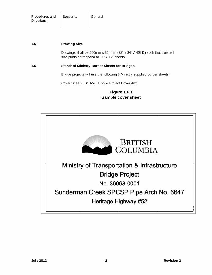
1.6 Standard Ministry Border Sheets for Bridges
Bridge projects will use the following 3 Ministry supplied border sheets:
Cover Sheet - BC MoT Bridge Project Cover.dwg
Figure 1.6.1 Sample cover sheet
Procedures and Directions
Section 1 General
July 2012 -3- Revision 2
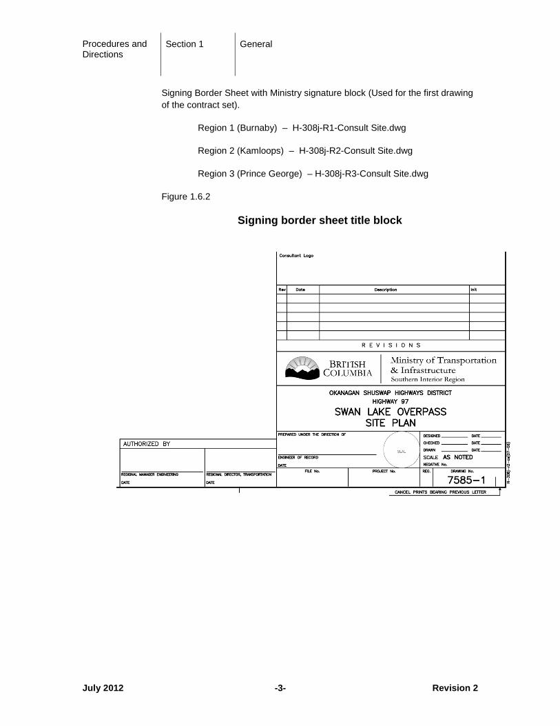
Signing Border Sheet with Ministry signature block (Used for the first drawing of the contract set).
Region 1 (Burnaby) – H-308j-R1-Consult Site.dwg
Region 2 (Kamloops) – H-308j-R2-Consult Site.dwg
Region 3 (Prince George) – H-308j-R3-Consult Site.dwg
Figure 1.6.2
Signing border sheet title block
Procedures and Directions
Section 1 General
July 2012 -4- Revision 2
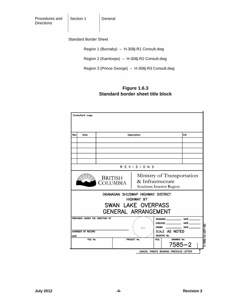
Standard Border Sheet
Region 1 (Burnaby) – H-308j-R1 Consult.dwg
Region 2 (Kamloops) – H-308j-R2 Consult.dwg
Region 3 (Prince George) – H-308j-R3 Consult.dwg
Figure 1.6.3 Standard border sheet title block
Procedures and Directions
Section 1 General
August 2018 -5- Revision 1
1.7 Signing of Drawings
One complete set of engineered contract drawings must be signed and sealed by the responsible professional engineer (Consultant Engineer for Consultant designs or Ministry Engineer for in-house designs), with the appropriate ministry official signatures to give authorization to proceed to tender. Copies of these signed and sealed drawings will be used for tendering and for construction contract award purposes.
For projects tendered by the Ministry, both the Regional Manager of Engineering and the Regional Director (or their equivalents in the case of Major Projects) must sign the tender drawings to give authorization to proceed to tender. Usually these signatures will appear on the first numbered drawing in the tender package. This is usually the Site Plan drawing for bridge projects. The cover sheet is not a numbered drawing and shall not be used for signatures.
Engineered Contract Drawings issued for tender that have not been signed or sealed by the responsible professional engineer must be authorized for use by the Regional or Branch Director in writing (email) and labeled as “Preliminary Not For Construction”.
Once the contract has been executed, the project manager is responsible to ensure that the original set of signed and sealed full size drawings are sent to headquarters Engineering Branch, attention: Chief Engineer.
Addenda Drawings issued during the tender period must be signed and sealed by the responsible professional engineer and posted as an addendum to the tender document package. All original signed and sealed Addenda drawings must be sent to the Chief Engineer once the contract has been executed. All seals shall be done with black ink, embossed seals are not acceptable.
Changes to full size drawings that are issued after contract award are also required to be signed and sealed by the responsible professional engineer and issued as a formal contract amendment. All original signed and sealed Amendment drawings must be sent to the Chief Engineer once the amendment has been executed.
All engineered contract full sized drawings must be clear, comprehensive, accurate, and include the following:
• project number, sub-project number;
• drawing number;
• description;
• date;
Procedures and Directions
Section 1 General
August 2018 -6- Revision 1
• revision, revision date, revision description and first initial and complete last name of the person doing the revisions, for all revisions;
• original signatures and ink seals (embossed seals are not acceptable because they do not copy or scan);
• all signature blocks provided must be signed off, by the responsible professional engineer and by the appropriate Ministry Officials as required;
• sketches, 8 ½ x 11 or any odd size sheets, need to be signed and sealed by the responsible professional engineer if included as contract drawings;
• Design Build Minor: site plans do not require the signature of a professional engineer but Concept drawings must be signed and sealed by the responsible professional engineer.
The signed and sealed full size original drawings must be scanned in order to produce the electronic PDF file(s) used for tendering. All 1/2 sized tender drawings must be produced from the full size drawing in order to keep the scale.
Note: “Issue for Tender” and “Issued for Construction” are not to be annotated on the Drawings.

Procedures and Directions
Section 2 Drawing Preparation
August 2007 -7- Revision 1
2 Drawing Preparation
2.1 Standard AutoCAD Template
Template files BC.MoT Bridge mm.dwt is available and contain standard layering, text and dimensioning settings shown in this section of the manual.
2.2 Layering and Line Types
Bridge design drawings will be produced with the layering system presented in this section and drawing entities must have line type and color determined by layer.
The layering and line type system should not be deviated from. The Plot Style Table (*.CTB file) must be included with any submission to the Ministry and with the as-built drawing files in case of a deviation.
Procedures and Directions
Section 2 Drawing Preparation
August 2007 -8- Revision 1
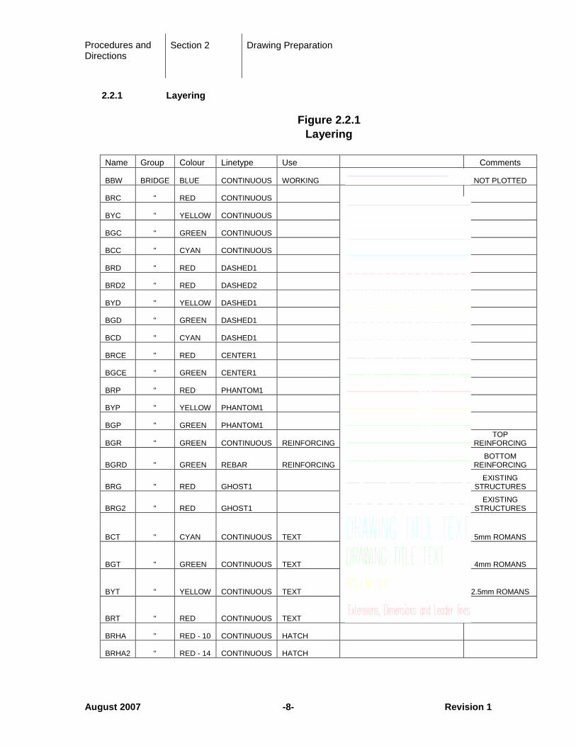
2.2.1 Layering
Figure 2.2.1 Layering
Name Group Colour Linetype Use Comments
BBW BRIDGE BLUE CONTINUOUS WORKING
NOT PLOTTED
BRC " RED CONTINUOUS
BYC " YELLOW CONTINUOUS
BGC " GREEN CONTINUOUS
BCC " CYAN CONTINUOUS
BRD " RED DASHED1
BRD2 " RED DASHED2
BYD " YELLOW DASHED1
BGD " GREEN DASHED1
BCD " CYAN DASHED1
BRCE " RED CENTER1
BGCE " GREEN CENTER1
BRP " RED PHANTOM1
BYP " YELLOW PHANTOM1
BGP " GREEN PHANTOM1
BGR " GREEN CONTINUOUS REINFORCING TOP
REINFORCING
BGRD " GREEN REBAR REINFORCING BOTTOM
REINFORCING
BRG " RED GHOST1 EXISTING
STRUCTURES
BRG2 " RED GHOST1 EXISTING
STRUCTURES
BCT " CYAN CONTINUOUS TEXT 5mm ROMANS
BGT " GREEN CONTINUOUS TEXT 4mm ROMANS
BYT " YELLOW CONTINUOUS TEXT 2.5mm ROMANS
BRT " RED CONTINUOUS TEXT
BRHA " RED - 10 CONTINUOUS HATCH
BRHA2 " RED - 14 CONTINUOUS HATCH
Procedures and Directions
Section 2 Drawing Preparation
August 2007 -9- Revision 1
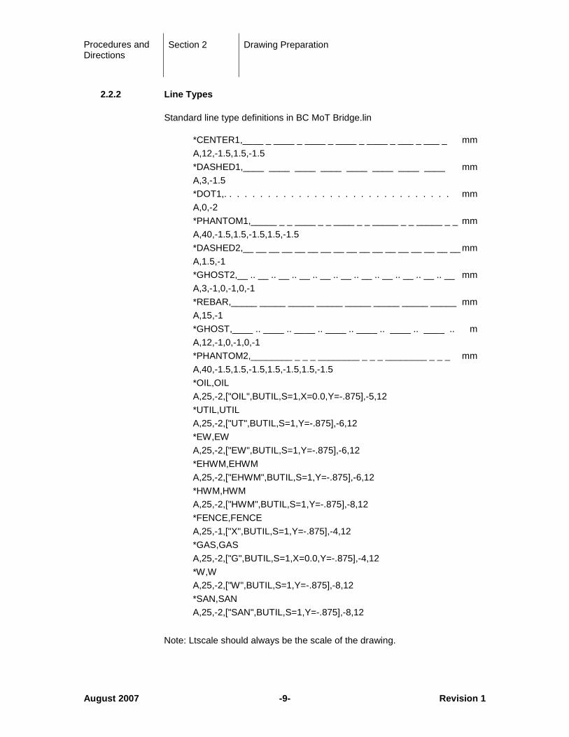
2.2.2 Line Types
Standard line type definitions in BC MoT Bridge.lin
*CENTER1,____ _ ____ _ ____ _ ____ _ ____ _ ___ _ ___ _ mm A,12,-1.5,1.5,-1.5 *DASHED1,____ ____ ____ ____ ____ ____ ____ ____ mm A,3,-1.5 *DOT1,. . . . . . . . . . . . . . . . . . . . . . . . . . . . . . mm A,0,-2 *PHANTOM1,_____ _ _ ____ _ _ ____ _ _ _____ _ _ _____ _ _ mm A,40,-1.5,1.5,-1.5,1.5,-1.5 *DASHED2,__ __ __ __ __ __ __ __ __ __ __ __ __ __ __ __ __ mm A,1.5,-1 *GHOST2,__ .. __ .. __ .. __ .. __ .. __ .. __ .. __ .. __ .. __ .. __ mm A,3,-1,0,-1,0,-1 *REBAR,_____ _____ _____ _____ _____ _____ _____ _____ mm A,15,-1 *GHOST,____ .. ____ .. ____ .. ____ .. ____ .. ____ .. ____ .. m A,12,-1,0,-1,0,-1 *PHANTOM2,________ _ _ _ ________ _ _ _ ________ _ _ _ mm A,40,-1.5,1.5,-1.5,1.5,-1.5,1.5,-1.5 *OIL,OIL A,25,-2,["OIL",BUTIL,S=1,X=0.0,Y=-.875],-5,12 *UTIL,UTIL A,25,-2,["UT",BUTIL,S=1,Y=-.875],-6,12 *EW,EW A,25,-2,["EW",BUTIL,S=1,Y=-.875],-6,12 *EHWM,EHWM A,25,-2,["EHWM",BUTIL,S=1,Y=-.875],-6,12 *HWM,HWM A,25,-2,["HWM",BUTIL,S=1,Y=-.875],-8,12 *FENCE,FENCE A,25,-1,["X",BUTIL,S=1,Y=-.875],-4,12 *GAS,GAS A,25,-2,["G",BUTIL,S=1,X=0.0,Y=-.875],-4,12 *W,W A,25,-2,["W",BUTIL,S=1,Y=-.875],-8,12 *SAN,SAN A,25,-2,["SAN",BUTIL,S=1,Y=-.875],-8,12
Note: Ltscale should always be the scale of the drawing.
Procedures and Directions
Section 2 Drawing Preparation
August 2007 -10- Revision 1
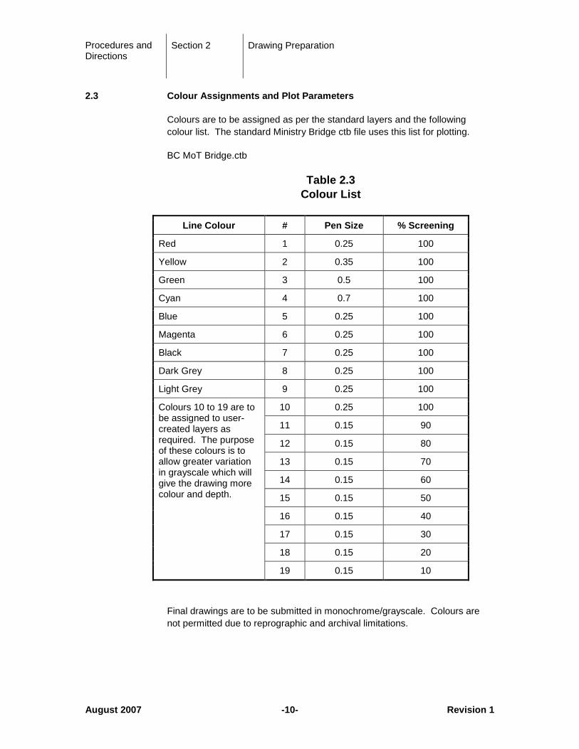
2.3 Colour Assignments and Plot Parameters
Colours are to be assigned as per the standard layers and the following colour list. The standard Ministry Bridge ctb file uses this list for plotting.
BC MoT Bridge.ctb
Table 2.3 Colour List
Line Colour # Pen Size % Screening
Red 1 0.25 100
Yellow 2 0.35 100
Green 3 0.5 100
Cyan 4 0.7 100
Blue 5 0.25 100
Magenta 6 0.25 100
Black 7 0.25 100
Dark Grey 8 0.25 100
Light Grey 9 0.25 100
Colours 10 to 19 are to be assigned to user-created layers as required. The purpose of these colours is to allow greater variation in grayscale which will give the drawing more colour and depth.
10 0.25 100
11 0.15 90
12 0.15 80
13 0.15 70
14 0.15 60
15 0.15 50
16 0.15 40
17 0.15 30
18 0.15 20
19 0.15 10
Final drawings are to be submitted in monochrome/grayscale. Colours are not permitted due to reprographic and archival limitations.

Procedures and Directions
Section 2 Drawing Preparation
August 2007 -11- Revision 1
2.4 Text Styles and Heights
The designer shall use consistent lettering height and font style. On Ministry bridge projects, the font BC_MOT_BRIDGE.shx should be used. This font is based on the standard AutoCAD font ROMANS the closest to Leroy template lettering style previously used. There are five normal text heights to be used on contract drawings. These heights are associated with specific AutoCAD colours and Ministry pen weight assignments. Text heights smaller than 1.75mm should not be used as they may be unreadable on a reduced set of drawings.
2.4.1 Standard Text Heights
Table 2.4.1 Standard Text Heights
Text Style
Plotted Text
Height (mm)
Scale
1 1:1
5 1:5
10 1:10
20 1:20
25 1:25
50 1:50
75 1:75
100 1:100
125 1:125
250 1:250
500 1:500
R1-8 1.75 1.75 8.75 17.5 35 43.75 87.5 131.25 175 218.75 437.5 875
R2-5 2.5 2.5 12.5 25 50 62.5 125 187.5 250 312.5 625 1250
R3 3 3 15 30 60 75 150 225 300 375 750 1500
R4 4 4 20 40 80 100 200 300 400 500 1000 2000
R5 5 5 25 50 100 125 250 375 500 625 1250 2500
Ltscale 1 5 10 20 25 50 75 100 125 250 500
Procedures and Directions
Section 2 Drawing Preparation
August 2007 -12- Revision 1
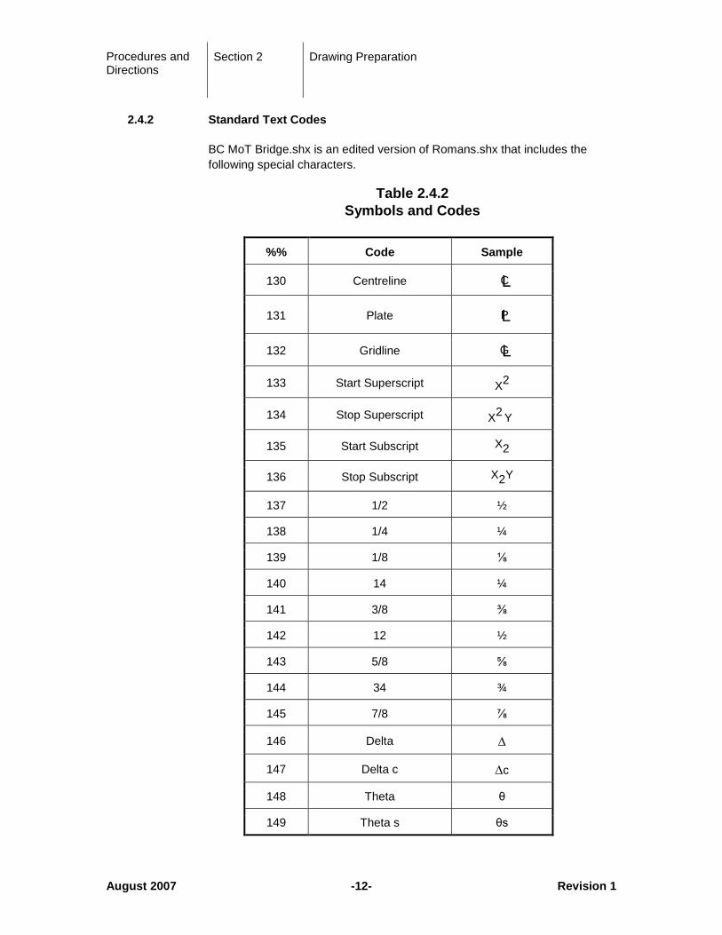
2.4.2 Standard Text Codes
BC MoT Bridge.shx is an edited version of Romans.shx that includes the following special characters.
Table 2.4.2 Symbols and Codes
%% Code Sample
130 Centreline CL
131 Plate PL
132 Gridline GL
133 Start Superscript X2
134 Stop Superscript X2 Y
135 Start Subscript X2
136 Stop Subscript X2Y
137 1/2 ½
138 1/4 ¼
139 1/8 ⅛
140 14 ¼
141 3/8 ⅜
142 12 ½
143 5/8 ⅝
144 34 ¾
145 7/8 ⅞
146 Delta ∆
147 Delta c ∆c
148 Theta θ
149 Theta s θs
Procedures and Directions
Section 2 Drawing Preparation
August 2007 -13- Revision 1
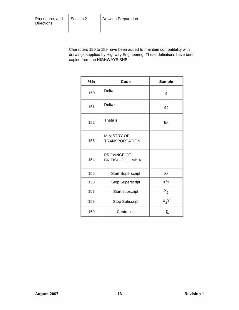
Characters 150 to 159 have been added to maintain compatibility with drawings supplied by Highway Engineering. These definitions have been copied from the HIGHWAYS.SHP.
%% Code Sample
150 Delta ∆
151 Delta c ∆c
152 Theta s θs
153 MINISTRY OF TRANSPORTATION
154 PROVINCE OF BRITISH COLUMBIA
155 Start Superscript X2
156 Stop Superscript X2Y
157 Start subscript X2
158 Stop Subscript X2Y
159 Centreline CL
Procedures and Directions
Section 2 Drawing Preparation
July 2012 -14- Revision 2
2.5 Dimensioning
The method of denoting measurement shall be consistent on all drawings. Elevations and stations shall be shown in metres, using a decimal point as a division between metres and millimetres, e.g.:
• Elevation: 100.040
• Station: 80 + 12.320
All other dimensions shall be shown in millimetres, e.g.:
• 12 415 or 1 080
• 150 x 180 x 12 angle
• 25 dia. Bolt
• 10M reinforcing bar
• 6 weld
The only exceptions to the above dimensioning rules are:
• Contours shall be shown thus: 280 or 98
• Elevations on the profile scale shall be shown thus: 105, 110, 115, etc.
• Stations on the profile scale shall be shown thus: 12 + 00, 12 + 25, etc.
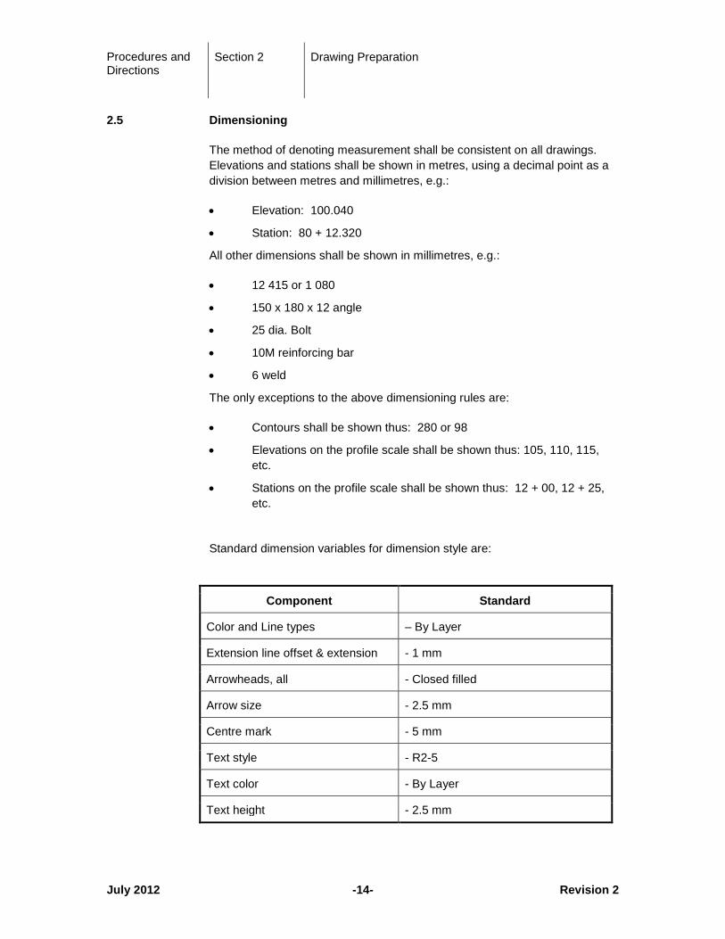
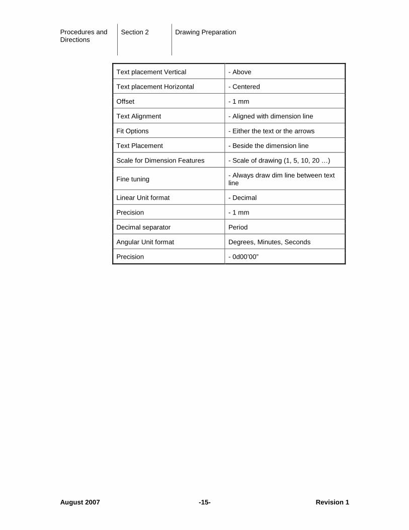
Standard dimension variables for dimension style are:
Component Standard
Color and Line types – By Layer
Extension line offset & extension - 1 mm
Arrowheads, all - Closed filled
Arrow size - 2.5 mm
Centre mark - 5 mm
Text style - R2-5
Text color - By Layer
Text height - 2.5 mm
Procedures and Directions
Section 2 Drawing Preparation
August 2007 -15- Revision 1
Text placement Vertical - Above
Text placement Horizontal - Centered
Offset - 1 mm
Text Alignment - Aligned with dimension line
Fit Options - Either the text or the arrows
Text Placement - Beside the dimension line
Scale for Dimension Features - Scale of drawing (1, 5, 10, 20 …)
Fine tuning - Always draw dim line between text line
Linear Unit format - Decimal
Precision - 1 mm
Decimal separator Period
Angular Unit format Degrees, Minutes, Seconds
Precision - 0d00’00”
Procedures and Directions
Section 2 Drawing Preparation
August 2007 -16- Revision 1
2.6 Drawing Units and Scales
The base unit for all structural drawings shall be millimeters (mm). If any other unit is used, a note shall be added to the drawing to identify the nonstandard units.
The base coordinate system does not need to be, nor will it be the same as the road design drawings. On the Site Plan and General Arrangement drawing, sufficient information must be given to allow the plans to be located in the road drawing coordinate system. This may be accomplished by referencing grid points, monuments or other survey points with known coordinates. (Note to Highway Designer: It is a simple process to INSERT with a 1/1000 scale, MOVE and ROTATE the Bridge drawing to align known coordinate points.)
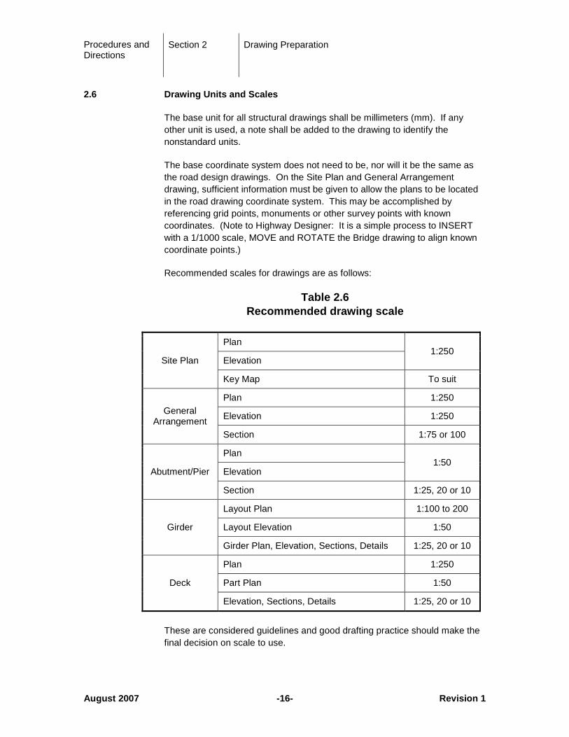
Recommended scales for drawings are as follows:
Table 2.6 Recommended drawing scale
Site Plan
Plan 1:250
Elevation
Key Map To suit
General Arrangement
Plan 1:250
Elevation 1:250
Section 1:75 or 100
Abutment/Pier
Plan 1:50
Elevation
Section 1:25, 20 or 10
Girder
Layout Plan 1:100 to 200
Layout Elevation 1:50
Girder Plan, Elevation, Sections, Details 1:25, 20 or 10
Deck
Plan 1:250
Part Plan 1:50
Elevation, Sections, Details 1:25, 20 or 10
These are considered guidelines and good drafting practice should make the final decision on scale to use.
Procedures and Directions
Section 2 Drawing Preparation
August 2007 -17- Revision 1
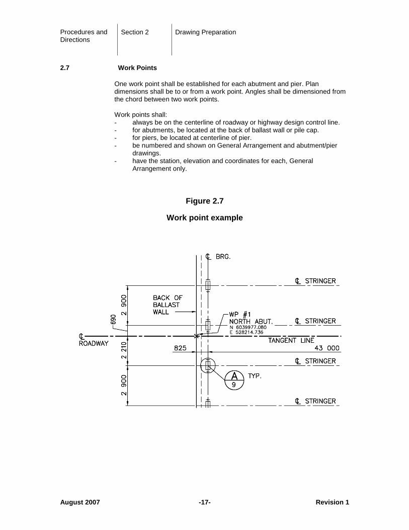
2.7 Work Points
One work point shall be established for each abutment and pier. Plan dimensions shall be to or from a work point. Angles shall be dimensioned from the chord between two work points. Work points shall: - always be on the centerline of roadway or highway design control line. - for abutments, be located at the back of ballast wall or pile cap. - for piers, be located at centerline of pier. - be numbered and shown on General Arrangement and abutment/pier drawings. - have the station, elevation and coordinates for each, General Arrangement only.
Figure 2.7
Work point example
Procedures and Directions
Section 2 Drawing Preparation
August 2007 -18- Revision 1
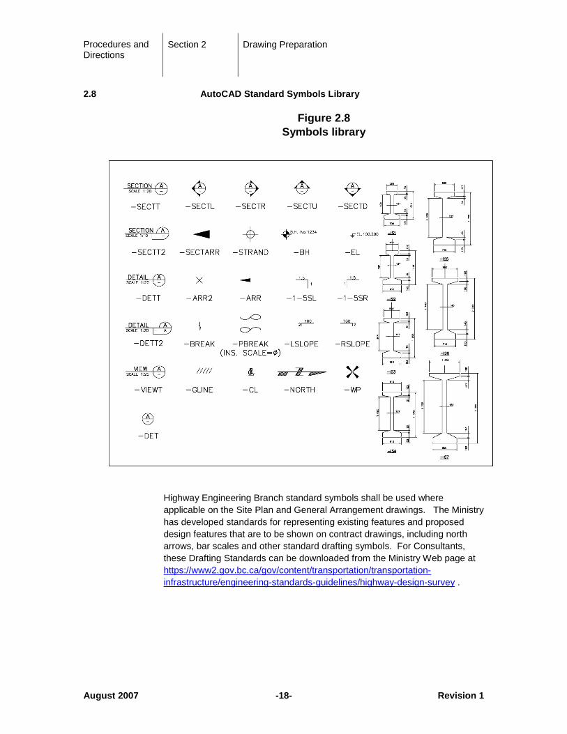
2.8 AutoCAD Standard Symbols Library
Figure 2.8 Symbols library
Highway Engineering Branch standard symbols shall be used where applicable on the Site Plan and General Arrangement drawings. The Ministry has developed standards for representing existing features and proposed design features that are to be shown on contract drawings, including north arrows, bar scales and other standard drafting symbols. For Consultants, these Drafting Standards can be downloaded from the Ministry Web page at https://www2.gov.bc.ca/gov/content/transportation/transportation-infrastructure/engineering-standards-guidelines/highway-design-survey .
Procedures and Directions
Section 2 Drawing Preparation
August 2007 -19- Revision 1
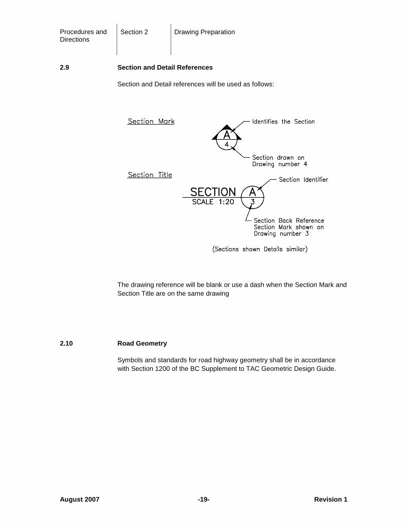
2.9 Section and Detail References
Section and Detail references will be used as follows:
The drawing reference will be blank or use a dash when the Section Mark and Section Title are on the same drawing
2.10 Road Geometry
Symbols and standards for road highway geometry shall be in accordance with Section 1200 of the BC Supplement to TAC Geometric Design Guide.
Procedures and Directions
Section 3 Drawing Standards
August 2007 -20- Revision 1
3 Drawing Standards
3.1 Preliminary Drawings
Preliminary Layout drawings are intended to:
• Acquaint the Ministry with general details of the proposed bridge;
• Obtain approval of the proposed bridge from the Ministry;
• Identify and solve general problems connected with the project prior to final design commencing.
The drawing should be generally pictorial with minimum detail. For example, no more than one precast beam needs to be shown in a cross-section, only a short length of railing needs to be indicated and only the perimeter of the riprap needs to be shown.
Printing need not be of contract drawing quality.
The layout should contain the following information:
• Approach fill details including paving, etc.
• Roadway, sidewalk, curb widths
• Roadway alignment (vertical, horizontal)
• Right-of-way
• Site preparation information
• Channel and riprap information
• Location of substructure units
• Deck details
• Retaining walls
• Clearances
• Approach curb details
• Railings, barrier and fence types
• Foundation, substructure and superstructure types
• Deck joint types
• Bearing types
• Site drainage details
• Span arrangement
• Total length

Procedures and Directions
Section 3 Drawing Standards
August 2007 -21- Revision 1
3.2 Contract Drawings
A set of Contract Drawings shall contain the following drawings, as applicable, in the order indicated. The content of the drawings should reflect the trades and sequence of construction anticipated in the project.
a) Cover Sheet b) General Notes and Drawing List c) Site Plan d) General Arrangement e) General Site Preparation Approach Fills, Channelization Riprap (if
part of bridge contract and if too extensive for General Arrangement) f) Abutments g) Piers and Bents h) Girders i) Bearings j) Deck k) Deck Joints m) Borehole Data n) Miscellaneous:
• Drain details
• Parapets and barriers and fences
• Slope paving/Riprap details
o) Stress Sheets
Procedures and Directions
Section 3 Drawing Standards
August 2007 -22- Revision 1
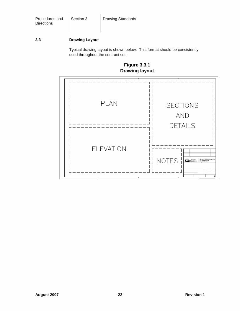
3.3 Drawing Layout
Typical drawing layout is shown below. This format should be consistently used throughout the contract set.
Figure 3.3.1 Drawing layout

Procedures and Directions
Section 3 Drawing Standards
September 2016 -23- Revision 2
3.4 Cover Sheet
This page has the Provincial logo, is unnumbered, has no title block and contains the following information:
PROVINCE OF BRITISH COLUMBIA
MINISTRY OF TRANSPORTATION & INFRASTRUCTURE
BRIDGE PROJECT
No. XXXXX
JOHN DOE BRIDGE
HIGHWAY No. or JOHN DOE ROAD
CONTRACT No. X – SUPERSTRUCTURE
A sample cover sheet is provided in the ACAD FILES link and is shown in Section 1.6.
3.5 General Notes and Drawing List
For Ministry bridge projects, the preference is to have ALL notes on the drawings where the information is considered relevant. For projects that require a large number of Notes, a separate drawing may be prepared that contains all the General Notes. In this case the Drawing List should be included on this General notes drawing if there is room.
3.6 Site Plan
The drawing should show the site as it will be at the time of arrival of the Contractor. The stations should proceed left to right.
• Scale 1:250
• Plan
• Profile on centreline of highway as working line with vertical and horizontal scales at 1:250.
• Geometry of new highway
• Profile of new highway
• Working lines
• Existing structure, roads, ditches, drains
• Existing fill placement including surcharge
• Existing riprap
Procedures and Directions
Section 3 Drawing Standards
August 2007 -24- Revision 1
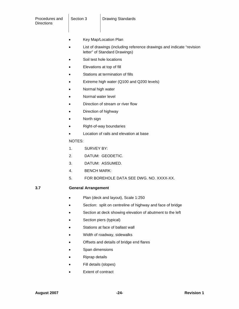
• Key Map/Location Plan
• List of drawings (including reference drawings and indicate “revision letter” of Standard Drawings)
• Soil test hole locations
• Elevations at top of fill
• Stations at termination of fills
• Extreme high water (Q100 and Q200 levels)
• Normal high water
• Normal water level
• Direction of stream or river flow
• Direction of highway
• North sign
• Right-of-way boundaries
• Location of rails and elevation at base
NOTES:
1. SURVEY BY:
2. DATUM: GEODETIC.
3. DATUM: ASSUMED.
4. BENCH MARK:
5. FOR BOREHOLE DATA SEE DWG. NO. XXXX-XX.
3.7 General Arrangement
• Plan (deck and layout), Scale 1:250
• Section: split on centreline of highway and face of bridge
• Section at deck showing elevation of abutment to the left
• Section piers (typical)
• Stations at face of ballast wall
• Width of roadway, sidewalks
• Offsets and details of bridge end flares
• Span dimensions
• Riprap details
• Fill details (slopes)
• Extent of contract
Procedures and Directions
Section 3 Drawing Standards
September 2016 -25- Revision 2
• Fixed, expansion bearings
• Deck joints
• Structural component description
• Utilities
• North sign
• Highway direction
• Superstructure, substructure, anchor bolt layout
• Clearance diagram – overheads, overpasses
• Detour Details (unless separate drawing)
NOTES:
1. DESIGN SPECIFICATION: - CAN/CSA-S6-14.
2. DESIGN LOADS:
- LIVE LOAD:
- FUTURE DEAD LOAD ALLOWANCE:
- EARTHQUAKE: A = 0.XX
- DESIGN TEMP.RANGE: Max/Min in oC
- RAINFALL: ? mm/15 Minutes
- WIND LOAD: 1/100 Year Reference= ? kPa
3. DESIGN SPEED: ? km/h
3.8 Abutments
• Plan
• Elevation
• Section on centre
• Section on wing wall
• General dimensions, reinforcement
• Work points, working lines
• Anchor bolt location relative to abutment (pictorially)
• Bearing seat and roadway elevations
• Note of bridge seat elevations to be confirmed, if not known
• Note on anchor bolt blockouts
Procedures and Directions
Section 3 Drawing Standards
March 2015 -26- Revision 2
• Blockout setting detail
• Bridge number detail
• Rock profiles
• Pile details
• Anticipated Pile Tip Elevations
• Maximum Pile Tip Elevations
• Maximum Factored Pile Design Loads
• Working floor
NOTES:
1. ALL CONCRETE TO HAVE A MINIMUM COMPRESSIVE STRENGTH OF 30 MPa AT 28 DAYS EXCEPT AS NOTED.
2. ALL EXPOSED EDGES OF CONCRETE TO BE CHAMFERED 20 UNLESS NOTED OTHERWISE.
3. ALL REINFORCING STEEL TO CONFORM TO CSA SPECIFICATION G30.18-M, GRADE 400R. (Specify 400W when required for seismic design)
4. ALL REINFORCING STEEL TO HAVE 60 COVER UNLESS NOTED OTHERWISE.
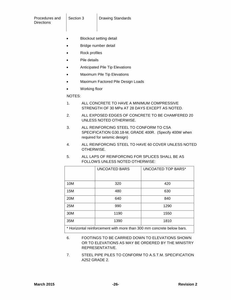
5. ALL LAPS OF REINFORCING FOR SPLICES SHALL BE AS FOLLOWS UNLESS NOTED OTHERWISE:
UNCOATED BARS UNCOATED TOP BARS*
10M 320 420
15M 480 630
20M 640 840
25M 990 1290
30M 1190 1550
35M 1390 1810
* Horizontal reinforcement with more than 300 mm concrete below bars.
6. FOOTINGS TO BE CARRIED DOWN TO ELEVATIONS SHOWN OR TO ELEVATIONS AS MAY BE ORDERED BY THE MINISTRY REPRESENTATIVE.
7. STEEL PIPE PILES TO CONFORM TO A.S.T.M. SPECIFICATION A252 GRADE 2.
Procedures and Directions
Section 3 Drawing Standards
March 2015 -27- Revision 2
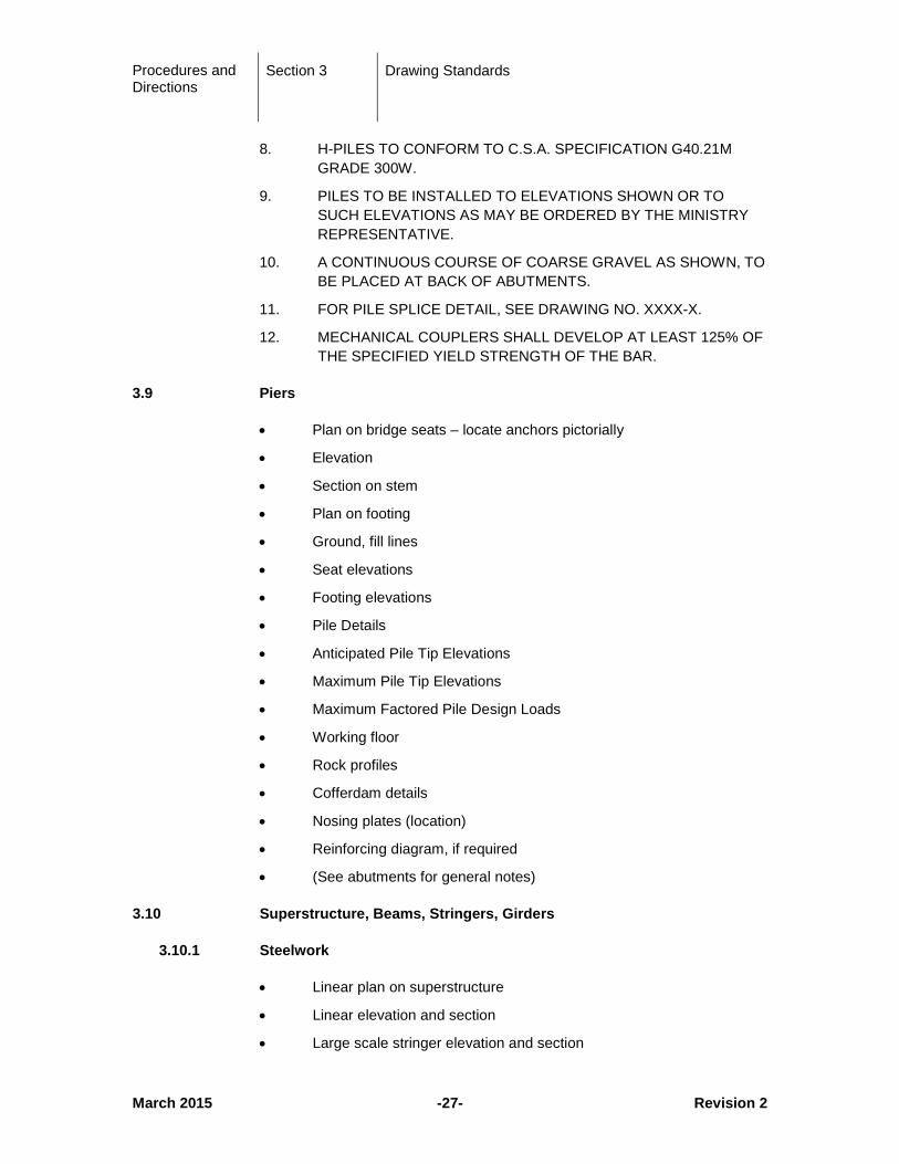
8. H-PILES TO CONFORM TO C.S.A. SPECIFICATION G40.21M GRADE 300W.
9. PILES TO BE INSTALLED TO ELEVATIONS SHOWN OR TO SUCH ELEVATIONS AS MAY BE ORDERED BY THE MINISTRY REPRESENTATIVE.
10. A CONTINUOUS COURSE OF COARSE GRAVEL AS SHOWN, TO BE PLACED AT BACK OF ABUTMENTS.
11. FOR PILE SPLICE DETAIL, SEE DRAWING NO. XXXX-X.
12. MECHANICAL COUPLERS SHALL DEVELOP AT LEAST 125% OF THE SPECIFIED YIELD STRENGTH OF THE BAR.
3.9 Piers
• Plan on bridge seats – locate anchors pictorially
• Elevation
• Section on stem
• Plan on footing
• Ground, fill lines
• Seat elevations
• Footing elevations
• Pile Details
• Anticipated Pile Tip Elevations
• Maximum Pile Tip Elevations
• Maximum Factored Pile Design Loads
• Working floor
• Rock profiles
• Cofferdam details
• Nosing plates (location)
• Reinforcing diagram, if required
• (See abutments for general notes)
3.10 Superstructure, Beams, Stringers, Girders
3.10.1 Steelwork
• Linear plan on superstructure
• Linear elevation and section
• Large scale stringer elevation and section
Procedures and Directions
Section 3 Drawing Standards
September 2016 -28- Revision 2
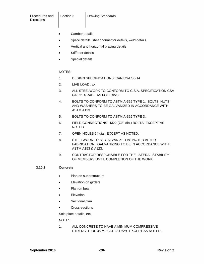
• Camber details
• Splice details, shear connector details, weld details
• Vertical and horizontal bracing details
• Stiffener details
• Special details
NOTES:
1. DESIGN SPECIFICATIONS: CAN/CSA S6-14
2. LIVE LOAD : xx
3. ALL STEELWORK TO CONFORM TO C.S.A. SPECIFICATION CSA G40.21 GRADE AS FOLLOWS:
4. BOLTS TO CONFORM TO ASTM A-325 TYPE 1. BOLTS, NUTS AND WASHERS TO BE GALVANIZED IN ACCORDANCE WITH ASTM A123.
5. BOLTS TO CONFORM TO ASTM A-325 TYPE 3.
6. FIELD CONNECTIONS - M22 (7/8” dia.) BOLTS, EXCEPT AS NOTED.
7. OPEN HOLES 24 dia., EXCEPT AS NOTED.
8. STEELWORK TO BE GALVANIZED AS NOTED AFTER FABRICATION. GALVANIZING TO BE IN ACCORDANCE WITH ASTM A153 & A123.
9. CONTRACTOR RESPONSIBLE FOR THE LATERAL STABILITY OF MEMBERS UNTIL COMPLETION OF THE WORK.
3.10.2 Concrete
• Plan on superstructure
• Elevation on girders
• Plan on beam
• Elevation
• Sectional plan
• Cross-sections
Sole plate details, etc.
NOTES:
1. ALL CONCRETE TO HAVE A MINIMUM COMPRESSIVE STRENGTH OF 35 MPa AT 28 DAYS EXCEPT AS NOTED.
Procedures and Directions
Section 3 Drawing Standards
August 2007 -29- Revision 1
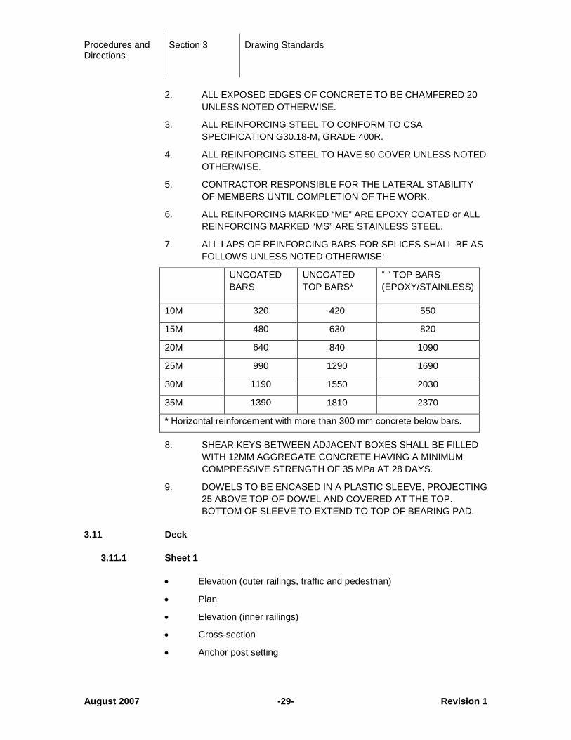
2. ALL EXPOSED EDGES OF CONCRETE TO BE CHAMFERED 20 UNLESS NOTED OTHERWISE.
3. ALL REINFORCING STEEL TO CONFORM TO CSA SPECIFICATION G30.18-M, GRADE 400R.
4. ALL REINFORCING STEEL TO HAVE 50 COVER UNLESS NOTED OTHERWISE.
5. CONTRACTOR RESPONSIBLE FOR THE LATERAL STABILITY OF MEMBERS UNTIL COMPLETION OF THE WORK.
6. ALL REINFORCING MARKED “ME” ARE EPOXY COATED or ALL REINFORCING MARKED “MS” ARE STAINLESS STEEL.
7. ALL LAPS OF REINFORCING BARS FOR SPLICES SHALL BE AS FOLLOWS UNLESS NOTED OTHERWISE:
UNCOATED BARS
UNCOATED TOP BARS*
“ “ TOP BARS (EPOXY/STAINLESS)
10M 320 420 550
15M 480 630 820
20M 640 840 1090
25M 990 1290 1690
30M 1190 1550 2030
35M 1390 1810 2370
* Horizontal reinforcement with more than 300 mm concrete below bars.
8. SHEAR KEYS BETWEEN ADJACENT BOXES SHALL BE FILLED WITH 12MM AGGREGATE CONCRETE HAVING A MINIMUM COMPRESSIVE STRENGTH OF 35 MPa AT 28 DAYS.
9. DOWELS TO BE ENCASED IN A PLASTIC SLEEVE, PROJECTING 25 ABOVE TOP OF DOWEL AND COVERED AT THE TOP. BOTTOM OF SLEEVE TO EXTEND TO TOP OF BEARING PAD.
3.11 Deck
3.11.1 Sheet 1
• Elevation (outer railings, traffic and pedestrian)
• Plan
• Elevation (inner railings)
• Cross-section
• Anchor post setting
Procedures and Directions
Section 3 Drawing Standards
August 2007 -30- Revision 1
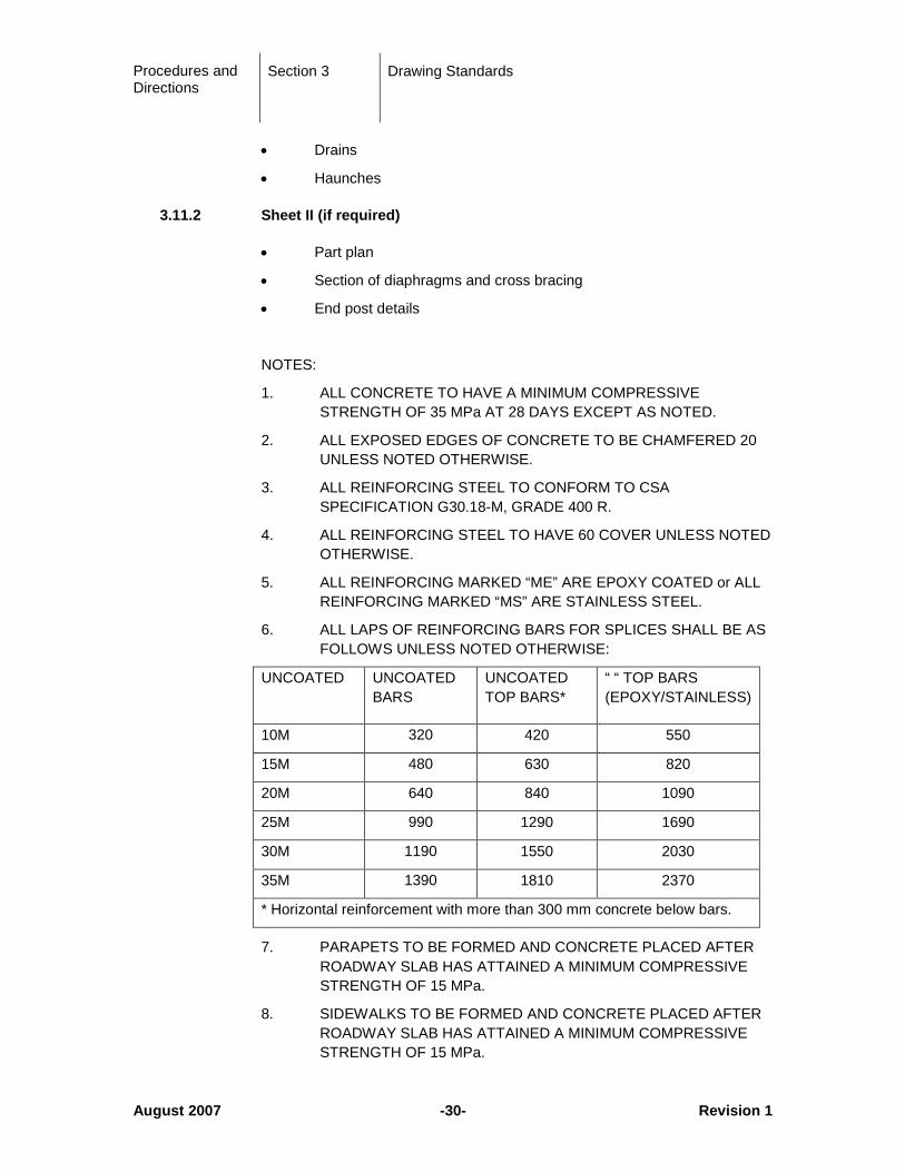
• Drains
• Haunches
3.11.2 Sheet II (if required)
• Part plan
• Section of diaphragms and cross bracing
• End post details
NOTES:
1. ALL CONCRETE TO HAVE A MINIMUM COMPRESSIVE STRENGTH OF 35 MPa AT 28 DAYS EXCEPT AS NOTED.
2. ALL EXPOSED EDGES OF CONCRETE TO BE CHAMFERED 20 UNLESS NOTED OTHERWISE.
3. ALL REINFORCING STEEL TO CONFORM TO CSA SPECIFICATION G30.18-M, GRADE 400 R.
4. ALL REINFORCING STEEL TO HAVE 60 COVER UNLESS NOTED OTHERWISE.
5. ALL REINFORCING MARKED “ME” ARE EPOXY COATED or ALL REINFORCING MARKED “MS” ARE STAINLESS STEEL.
6. ALL LAPS OF REINFORCING BARS FOR SPLICES SHALL BE AS FOLLOWS UNLESS NOTED OTHERWISE:
UNCOATED
UNCOATED BARS
UNCOATED TOP BARS*
“ “ TOP BARS (EPOXY/STAINLESS)
10M 320 420 550
15M 480 630 820
20M 640 840 1090
25M 990 1290 1690
30M 1190 1550 2030
35M 1390 1810 2370
* Horizontal reinforcement with more than 300 mm concrete below bars.
7. PARAPETS TO BE FORMED AND CONCRETE PLACED AFTER ROADWAY SLAB HAS ATTAINED A MINIMUM COMPRESSIVE STRENGTH OF 15 MPa.
8. SIDEWALKS TO BE FORMED AND CONCRETE PLACED AFTER ROADWAY SLAB HAS ATTAINED A MINIMUM COMPRESSIVE STRENGTH OF 15 MPa.
Procedures and Directions
Section 3 Drawing Standards
August 2007 -31- Revision 1
(NOTE: Designer to specify either 9 or 10 as required.)
9. SPLICING OF TRANSVERSE BARS IS NOT PERMITTED. LONGITUDINAL BARS MAY BE SPLICED; SPLICES ARE TO BE STAGGERED SO THAT NOT MORE THAN EVERY THIRD BAR IS SPLICED AT ANY CROSS SECTION OF THE DECK.
10. SPLICES TO BE STAGGERED SO THAT NOT MORE THAN EVERY THIRD BAR IS SPLICED AT ANY SECTION OF THE DECK. FOR TRANSVERSE BAR SPLICES, SEE DETAIL DRAWING NO. XXXX-X.
11. SCREEDS FOR DECK CONCRETE SHALL BE SET TO GIVE A UNIFORM GRADE FROM END TO END OF THE BRIDGE AND TO ACCOMMODATE HOGGING OF THE STRINGERS WHICH IS TO BE MEASURED IN THE FIELD.
12. DEFLECTION AND DIFFERENCE IN CAMBER WILL BE ACCOMMODATED BY DECK SCREED ELEVATIONS SUPPLIED BY THE MINISTRY REPRESENTATIVE. HAUNCH HEIGHTS WILL VARY AS REQUIRED TO MAINTAIN A CONSTANT DECK SLAB THICKNESS BETWEEN STRINGERS.
13. CONCRETE FOR EACH DECK SECTION TO BE PLACED IN ONE CONTINUOUS OPERATION.
14. FOR ELECTRICAL DETAILS FOR LIGHTING, SEE DRAWING NO. XXXX-X.
15. CONTRACTOR RESPONSIBLE FOR THE LATERAL STABILITY OF MEMBERS UNTIL COMPLETION OF THE WORK.
3.12 Deck Joints
• Plan
• Section
• Details
• Table showing gap for various ambient temperatures
• Notes
3.13 Bearings
• Layout
• Plan and section of each type of bearing
• anchor bolt details
• anchor blockouts
• Bearing replacement procedures, including jacking locations and jacking loads
Procedures and Directions
Section 3 Drawing Standards
August 2007 -32- Revision 1
• The tabulation of permanent vertical load, total vertical load, and bearing pressures at serviceability limit states design shall be shown on the drawing for each bearing.
3.14 Miscellaneous Details
• Drain details
• Slope paving and riprap details
• Waterproofing details
• Measures to prevent bird roosting
• Parapet, barriers and fences including transitions
• Lane marking
• Approach slabs
3.15 Stress Sheets
The following combinations of the moment and shear diagrams for the Ultimate Limit States design of the continuous or semi-continuous (where applicable) structures shall be shown as follows:
A
B
(B + C)
(B + C + D)
(B + C + D + E)
(B + C + D + E + F)
where:
A = Factored Resistance
B = Factored non-composite dead load moment and shear (including effect of deck pour sequence, if any)
C = Factored composite dead load moment and shear (including effect of deck pour sequence, if any).
D = Factored live load moment and shear (consideration shall be given to displaying maximum moment and maximum shear, or maximum moment with corresponding concurrent shear and maximum shear with corresponding concurrent moment)
Procedures and Directions
Section 3 Drawing Standards
August 2007 -33- Revision 1
E = Factored dynamic load allowance for moment and shear
F = Factored moments and shears from shrinkage, creep, temperature, prestress, etc. (where applicable)
Tabulations of the load factors and distribution factors shall also be included. The method of obtaining the distribution factor shall be indicated (e.g. S6-06 Clause 5.7.1 or grillage analysis or other method).
3.16 Borehole Logs
The Borehole Logs for the bridge site are prepared by the Geotechnical Engineer in accordance with standard Ministry format as described in “Geotechnical and Materials Engineering Standards for Bridge Foundation Investigations (January 1991) – Section 2, Summary Log available at: (http://www.th.gov.bc.ca/publications/eng_publications/eng_pubs.htm#top)
All geotechnical test hole, test pit and cone penetration test locations are to be shown on the Site Plan with the association test hole reference number.
3.17 Drawing Revisions
Once a project drawing has been approved by the Ministry, any further alterations or amendments must be recorded in the revision space provided. A major revision, which completely alters the intent of the original approved drawing, must be re-approved.
When the General Arrangement drawing is amended to show ROW as purchased, the original boundary or area shall not be removed. Rather, the amended ROW boundary shall be shown with a heavier line and note the increase or decrease in area.
The location of the revised details on the contract drawings shall be indicated by the “revision letter” enclosed within a triangle. Revision letters shall be assigned sequentially from “A” to “Z” and entered into the revision block.
All existing revision symbols shall remain on the drawings when subsequent revisions are indicated.
Drawings shall NOT contain “Issued for Tender” or “Issued for Construction”. Signed and sealed drawings shall be submitted for tendering and all further revisions shall be identified as noted above.
If major revisions are required, consideration should be given to deleting the entire drawing and re-issuing under a new drawing number.
Procedures and Directions
Section 3 Drawing Standards
August 2007 -34- Revision 1
3.18 Drawing Submission Requirements
3.18.1 Drawings for Review
Drawings submitted to the Ministry for review as specified in Contract or RFP (minimum Conceptual, 70% and 100%) shall consist of one full size hard copy, one half size hard copy and an electronic copy in *.PDF format (Adobe Portable Document Format).
3.18.2 Final Contract Drawings
A minimum of one full size hard copy of the stamped and signed contract drawings will be supplied with a CD containing all drawings. When the contract drawings are finalized and plotted for signature, the plot versions of the drawings shall be archived onto the CD. The CD and signed originals make up part of the contract and are property of the Ministry of Transportation. The project CD shall be labeled as follows:
• Drawing Series Number
• Bridge Name
• Consultant
• Drawing templates
• Standard drawings
Procedures and Directions
Section 4 Construction Engineering Submissions
August 2007 -35- Revision 1
4 Construction Engineering Submissions
4.1 Shop Drawings
4.1.1 Hard Copy (Paper) Submission
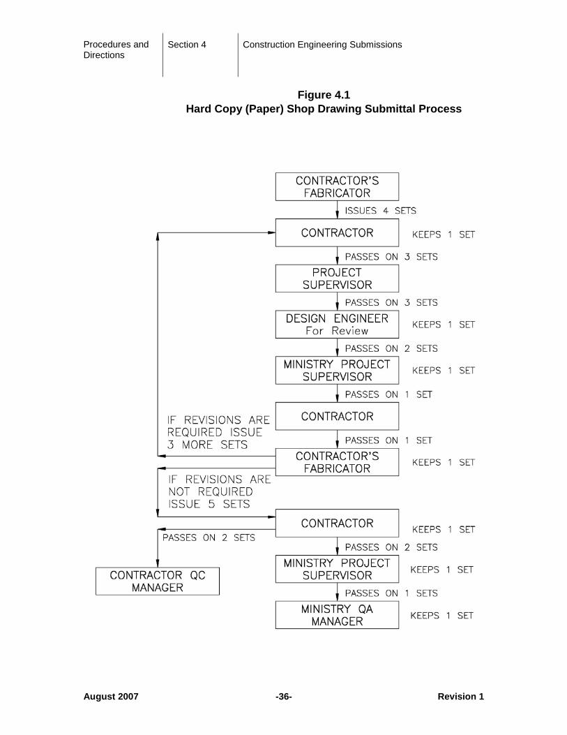
In general, the procedure described below and shown in Figure 4.1 shall be followed regarding the hard copy (paper) submission of shop drawings.
The Contractor’s fabricator shall create and submit four sets of shop drawings to the Contractor. The Contractor shall keep one set and shall submit three sets to the Ministry Project Supervisor. The Ministry Project Supervisor shall forward three sets to the Design Engineer, who will review the drawings for general compliance with the contract requirements. The Design Engineer shall keep one set and pass 2 sets to the Ministry Project Supervisor who shall keep one set and pass one set on to the Contractor. The Contractor shall then pass one set to the Fabricator. If revisions are required, the Fabricator shall carry out the revisions and then resubmit four sets to the Contractor to begin the cycle again.
When no exceptions are taken to the drawings, the Fabricator shall issue five sets of drawings to the Contractor. The Contractor shall keep one set and pass four sets on to the Ministry Project Supervisor. The Ministry Project Supervisor shall keep one set and pass two sets to the Plant Inspector and one set to the Regional Bridge Section.
The process described above is illustrated in Figure 4.1 following.
Procedures and Directions
Section 4 Construction Engineering Submissions
August 2007 -36- Revision 1
Figure 4.1 Hard Copy (Paper) Shop Drawing Submittal Process
Procedures and Directions
Section 4 Construction Engineering Submissions
August 2007 -37- Revision 1
4.1.2 Electronic Submission
Only with the Ministry Representative (or Project Supervisor) permission, shop drawings may be submitted and distributed electronically. Before giving permission, the Ministry Representative must confirm with all parties that they have the capacity to handle electronic submissions.
Electronic Submission will follow the same distribution pattern as hard copies except as noted below.
The Fabricator shall create shop drawings in AutoCAD and save them as both *.DWG and *.PDF (Adobe Portable Document Format) files. The Fabricator shall electronically forward the *.PDF files to the Contractor who, at his discretion and/or in keeping with requirements of his Quality Control Plan, may print a copy for his records. The Contractor shall electronically forward the drawings to the Project Supervisor.
The Design Engineer shall print the required number of copies and shall review the drawings as per a hard copy submission.
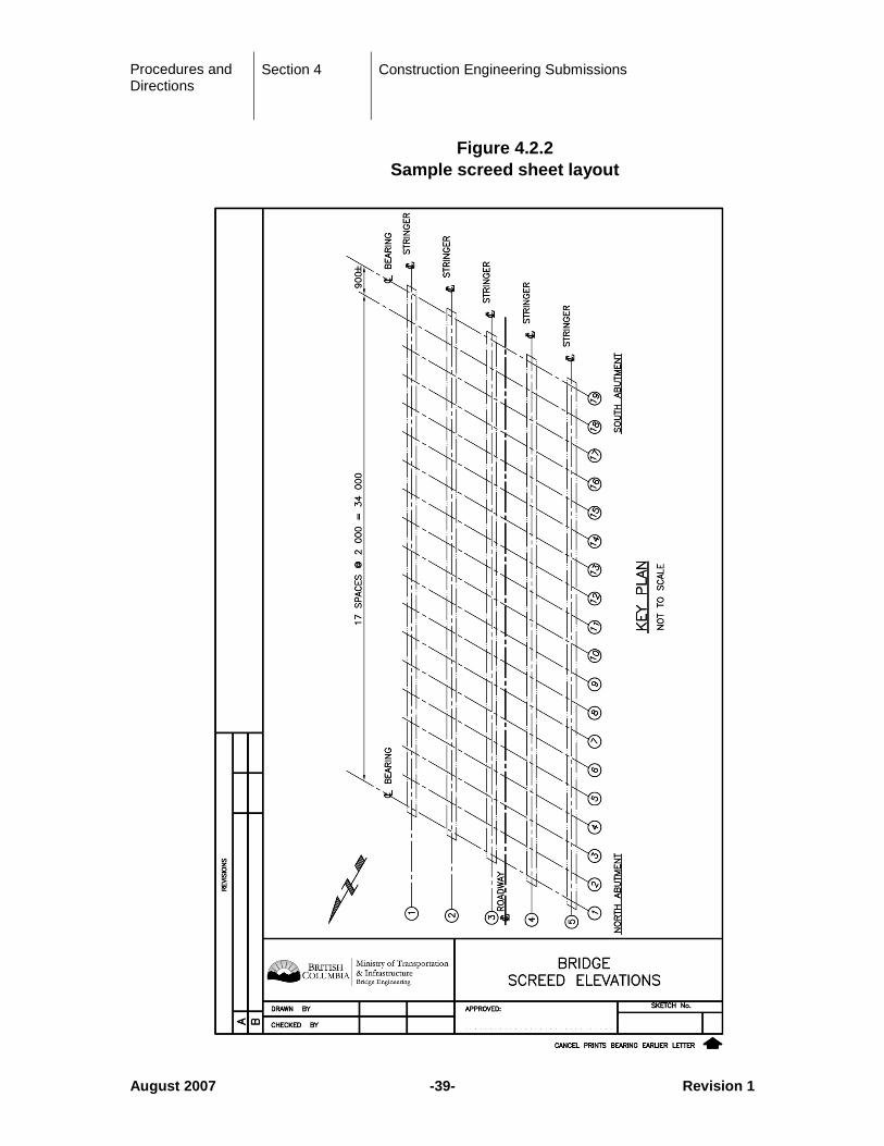
4.2 Deck Screeds
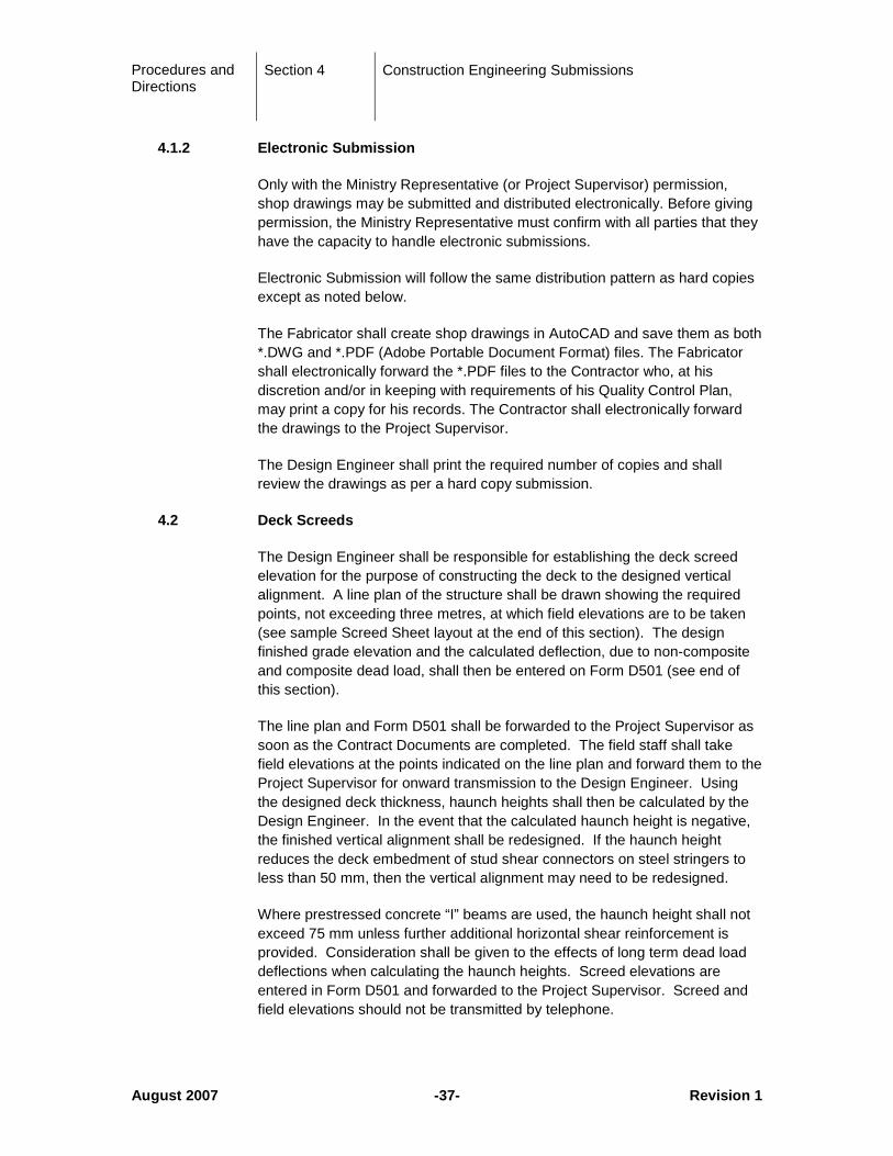
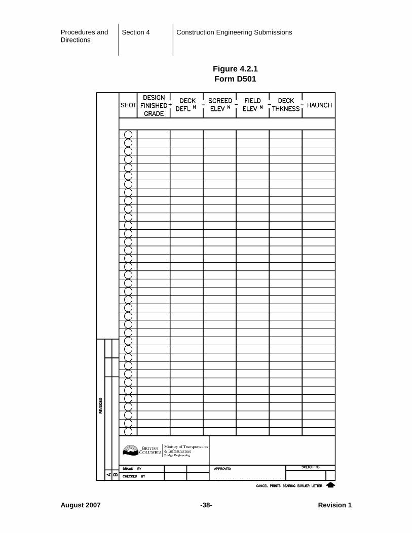
The Design Engineer shall be responsible for establishing the deck screed elevation for the purpose of constructing the deck to the designed vertical alignment. A line plan of the structure shall be drawn showing the required points, not exceeding three metres, at which field elevations are to be taken (see sample Screed Sheet layout at the end of this section). The design finished grade elevation and the calculated deflection, due to non-composite and composite dead load, shall then be entered on Form D501 (see end of this section).
The line plan and Form D501 shall be forwarded to the Project Supervisor as soon as the Contract Documents are completed. The field staff shall take field elevations at the points indicated on the line plan and forward them to the Project Supervisor for onward transmission to the Design Engineer. Using the designed deck thickness, haunch heights shall then be calculated by the Design Engineer. In the event that the calculated haunch height is negative, the finished vertical alignment shall be redesigned. If the haunch height reduces the deck embedment of stud shear connectors on steel stringers to less than 50 mm, then the vertical alignment may need to be redesigned.
Where prestressed concrete “I” beams are used, the haunch height shall not exceed 75 mm unless further additional horizontal shear reinforcement is provided. Consideration shall be given to the effects of long term dead load deflections when calculating the haunch heights. Screed elevations are entered in Form D501 and forwarded to the Project Supervisor. Screed and field elevations should not be transmitted by telephone.
Procedures and Directions
Section 4 Construction Engineering Submissions
August 2007 -38- Revision 1
Figure 4.2.1 Form D501
Procedures and Directions
Section 4 Construction Engineering Submissions
August 2007 -39- Revision 1
Figure 4.2.2 Sample screed sheet layout
Procedures and Directions
Section 4 Construction Engineering Submissions
August 2007 -40- Revision 1
4.3 Record Drawings
4.3.1 Submission and Distribution
At the completion of construction, the Project Supervisor will submit marked up prints of all contract drawings showing as-built changes to the Design Engineer (via the Consultant Liaison Engineer for Consultant designs).
• The Consultant Liaison Engineer will forward the as-built field drawings and shop drawings to the Design Consultant
• The Design Engineer shall complete record AutoCAD drawings in accordance with the marked up prints. The format for drawing revisions will be as per Section 3.17 Drawing Revisions.
• The Design Consultant shall return record AutoCAD drawings and CDs, to the Consultant Liaison Engineer in accordance with 4.3.2 - Preparation
4.3.2 Preparation
One full sized set of record drawings shall be provided by the Design Consultant to the Ministry. These record drawings shall be signed by the Design Engineer and all other signature blocks shall state, “ORIGINAL SIGNED BY name (print the name of the original signature).
The Design Consultant shall also scan the full sized signed record drawings to create an electronic file for each drawing in *.PDF format (Adobe Portable Document Format). These electronic files of each record drawing shall also be provided to the Ministry on a CD. CDs shall be labeled to indicate bridge number, bridge name, date of construction, drawing numbers included on the CD. All drawings on CDs shall be verified before submission for archiving purposes
One (1) set of record AutoCAD drawings on CD or other media (non-compressed files) shall also be provided to the Ministry at the same time for archiving as specified below:
• One copy of each final drawing (individual drawing files that make up the final drawing need not be supplied)
• CDs shall be labeled to indicate bridge number, bridge name, date of construction, drawing numbers included on the CD.
• Load as many drawings as possible on one CD without compressing the Files
• All drawings on CDs shall be verified before submission for archiving purposes

Procedures and Directions
Section 5 Regulatory Submission Requirements
August 2007 -41- Revision 1
5 Regulatory Submission Requirements
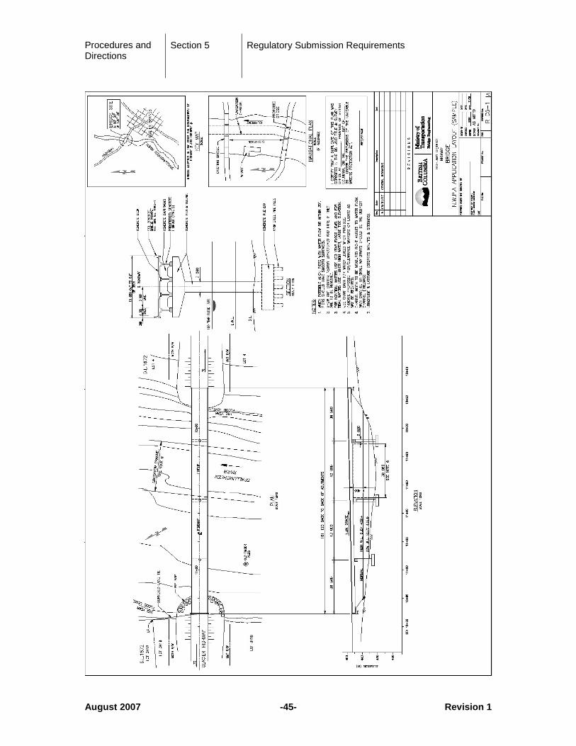
5.1 Application for Construction Under the Navigable Waters Protection Act
When a bridge spans “Navigable Waters”, an application to construct must be made to the Federal Government under the Navigable Waters Protection Act and the Rail, Navigable Waters Coordinator shall coordinate contact with Transport Canada about clearance provisions and safety appurtenances
“Navigable Waters” are described as any body of water, natural or man made, capable of carrying water borne vessel. If the body of water is considered to be marginal for navigation then a review will be coordinated by the Rail, Navigable Waters Coordinator. This review is generally carried out with stakeholders and Transport Canada and any Harbours Board (Port Authorities) or other authority having jurisdictional responsibilities for the Navigable Waters Protection Act. To allow this evaluation several pictures of the watercourse and a location description are required.
In general Navigable Waters require a vertical clearance capable of allowing passage of the largest air draft vessel at the 100 year flood level or the HHWLT (Higher High Water, Large Tide). This allowance also includes a calculation of maximum wave height. For small watercourses capable of carrying only canoes, kayaks and other small craft a clearance of 1.7 m above the 100 year flood level is usually considered adequate. For small watercourses less clearance can be considered if cost and road design factors are compromised significantly.
Transport Canada, having authority of works over or in Navigable Waters, can declare other clearance requirements. Vessel Surveys and studies may also be required to determine clearance requirements and navigable areas and channel(s) within the waterway.
Transport Canada can also indicate the preferred location, alignment and dimension of navigable channel(s), lights and markers (etc.) to ensure the safety of water users. In general piers should be aligned within 10 degrees of river flow (possibly 20 degrees for very slow moving water) and have smooth and continuous faces. For structures on shipping channels, or waters with ice floes or in fast moving rivers with debris, piers shall be designed to withstand impact loading.
Reconstruction of a previously approved structure may not require a full application if the work does not alter the physical dimension of the navigable channel(s). This should be determined through consultation with Transport Canada.
Temporary works, facilities and equipment that may be present in any navigable area or works that require temporary alteration to the operation of a

Procedures and Directions
Section 5 Regulatory Submission Requirements
August 2007 -42- Revision 1
moveable span must be coordinated by Rail, Navigable Waters Coordinator with Transport Canada, Harbours Board (Port Authorities) and known mariners. Notice to Mariners, advertising, warning signs and, occasionally, mitigation may be required to ensure the safety of work crews and mariners. Construction procedures, limits of temporary works and clearances, schedules, lighting/signage/markers and communication procedures will be written into the contract as required.
The following is the preferred procedure for filling the applications:
1. As soon as the general details of the structure are known, a general layout drawing, entitled “NWPA Application Layout” is prepared. General details often require negotiation with Transport Canada and Harbours Board (Port Authorities) to ensure the proposed design is conceptually satisfactory.
The drawing should include:
a) Plan and elevation of the bridge with general dimension of total bridge length, span lengths, width of superstructure, width of approaches, width of piers, elevation and grade of deck, depth of stringers etc. Luminaires and required navigational lighting, signs and markers are also required to be shown.
b) Direction of water flow
c) Section of bridge showing river pier and general construction details
d) Nearby landmarks or significant marine features
e) Road name
f) Bearings of bridge
g) Width of water lot
h) Width and location of the water course with contours and the navigation channel for at least 40 m up and downstream of small bridges (20 m length or less) and at least 100 m for larger bridge. A large-scale “marine” map may be added to the drawing if required.
i) Clearance above 100-year flood level in non-tidal waters or the HHWLT (Higher High Water, Large Tide).
j) Legal description of property at each end of the bridge
Procedures and Directions
Section 5 Regulatory Submission Requirements
August 2007 -43- Revision 1
k) Key map (including Longitude and Latitude of the bridge location)
l) Standard note that a duplicate has been filed in the appropriate Land Titles Office or with the local Government Agent’s Office.
m) Location and description of nearby existing structures and a note if they are to be removed
n) The vertical clearance above 100-year flood level in non-tidal waters or the HHWLT (Higher High Water, Large Tide) of the existing or nearby bridge.
o) This drawing should be used for the NWPA application only.
p) An Environmental checklist is to be filled out by the Project Manager or Environmental Coordinator and forwarded to the Rail, Navigable Waters Coordinator along with relevant environmental reports (four copies), correspondence and environmental contact list.
2. The completed drawing and environmental information is provided to the Rail, Navigable Waters Coordinator who is responsible for continuing this application process. This drawing should not be used for construction purposes.
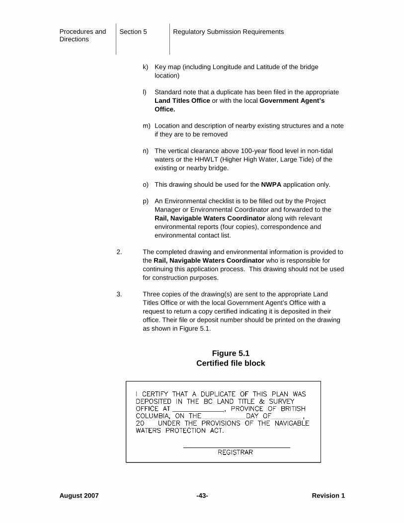
3. Three copies of the drawing(s) are sent to the appropriate Land Titles Office or with the local Government Agent’s Office with a request to return a copy certified indicating it is deposited in their office. Their file or deposit number should be printed on the drawing as shown in Figure 5.1.
Figure 5.1
Certified file block
Procedures and Directions
Section 5 Regulatory Submission Requirements
August 2007 -44- Revision 1
4. The formal application is made to Canada Ministry of Transport in Vancouver with ten copies of the drawing and four copies of environmental information. Copies are forwarded to the Project Manager or Designer, Regional Director and the District Highways Manager. The letter should describe known or probable navigation, navigation studies where applicable, any features which minimize the impact on navigation, the proposed date of construction, and any temporary conditions that may be known or stipulated in the contract. Normally approval takes about 4-6 months; therefore it is imperative that the process start at the earliest possible date.
5. When Canada Ministry of Transport in Vancouver has completed its initial investigation, they will advise the Ministry that it is in order to advertise the project.
6. The project is advertised in at least two local newspapers and in the Canada Gazette.
7. After waiting for one month, the proof of advertising is sent to Canada Ministry of Transport. If there have been no objections to the project, the formal approval will be issued in due course.
8. A copy of the approval document and the conveying letter are sent to the Project Manager or Designer, Regional Director and District Transportation Manager.
Procedures and Directions
Section 5 Regulatory Submission Requirements
August 2007 -45- Revision 1
Procedures and Directions
Section 5 Regulatory Submission Requirements
August 2007 -46- Revision 1
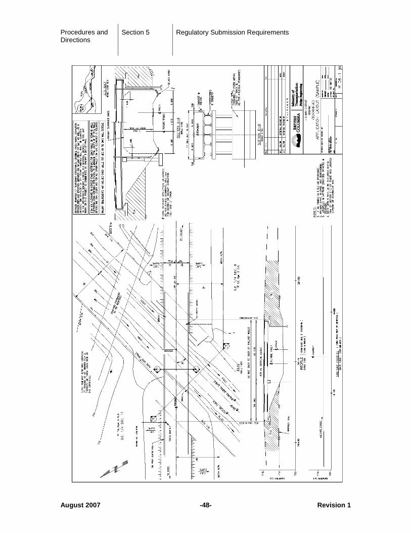
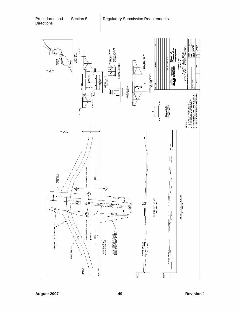
5.2 Application for Construction of Railway Overheads and Underpasses
When a grade separation, either an Overhead (Road structure) or underpass (railway structure) an application must be made to the appropriate authorities in accordance with the suitable provincial or federal legislation.
The Rail, Navigable Waters Coordinator shall contact the Railway about future provisions of facilities and safety appurtenances. This should be done before the alignment, concept and layout are fixed.
The preferred procedure for filing the application is as follows:
1. As soon as the location and general details of the structure are known, a general layout drawing, entitled “Application Layout” is prepared.
The drawing should include:
a) Plan and elevation of the bridge
b) Section of bridge showing pier and general construction details
c) Key map (longitude and latitude of the bridge location)
d) Road name
e) Bearings of bridge, angle of crossing, name of Railway, railway mile and subdivision
f) Width of right-of-way
g) Width and location, railway clearances including future railway facilities
h) Location of existing and future utilities
i) Legal description of property at each end of the bridge
j) Standard note on construction required by Railway Authorities
k) Location and description of existing nearby structures and if they will be removed or modified
l) Details of drainage off the structure and area adjacent to the rail right-of-way.
2. The completed drawing is handed to the Rail, Navigable Waters Coordinator who is responsible for continuing this application process. This drawing should not be used for construction purposes.
Procedures and Directions
Section 5 Regulatory Submission Requirements
August 2007 -47- Revision 1
3. Federally chartered railways are governed by Acts and regulations under the authority of the Railway Safety Directorate and Canadian Transportation Agency. The Rail, Navigable Waters Coordinator will negotiate with the railway for cost and facility responsibilities and, if possible, conclude an agreement allowing the (re)construction of the facility. The agreement is then passed to the Canadian Transportation Agency to provide an Order filing the agreement and attesting to its completeness. The Railway Safety Act requires that a Notice be issued describing the proposal and, when construction is complete, that an affidavit be issued by the engineer responsible for the work.
If an agreement can not be concluded with the railway company then the Canadian Transportation Agency can resolve disputes and will issue an Order or Decision authorizing construction providing all the responsibilities and conditions. The Canadian Transportation Agency will, by law, require that an environmental report satisfying the requirements of CEAA (Canadian Environmental Assessment Act) be attached to any application for resolution.
4. Provincially chartered railways are governed by Acts and regulations under the authority of the Ministry of Community, Aboriginal and Women’s Services. The Rail, Navigable Waters Coordinator will negotiate with the railway for cost and facility responsibilities and, if possible, conclude an agreement allowing (re)construction of the facility. An application is then made to the Ministry of Community, Aboriginal and Women’s Services for the issuance of a Certificate allowing construction.
5. The application, in general terms should describe the roadway traffic effects and the cost sharing requests, the proposed date of construction and any construction allowances that may be required. Normally approval takes about six months; therefore it is imperative that the process start at the earliest possible date.
6. A copy of the approval document and the conveying letter are sent to the Project Manager/Design Coordinator, Regional Director and District Transportation Manager.
Procedures and Directions
Section 5 Regulatory Submission Requirements
August 2007 -48- Revision 1
Procedures and Directions
Section 5 Regulatory Submission Requirements
August 2007 -49- Revision 1
Procedures and Directions
Section 5 Regulatory Submission Requirements
August 2007 -50- Revision 1
5.3 Clearances over Railways
• Centre to centre of tracks: 4.57 m/15 ft (typical)
• Vertical: 7.16 m/23 ft 6 ins above the base of the rail (Federal Railways) or 6.86 m/22 ft 6 ins above top of rail (Provincial Railways)
• Horizontal: 5.50 m/18 ft (Federal Railways) or 2.60 m/8 ft 6 ins (Provincial Railways) from the centreline of track
For each degree of curvature of the track, the horizontal clearance shall be increased by 50 mm each side of track.
Crash walls should be considered for any structures with substructure components including piers and mechanically stabilized earth walls within 7.65 m /25 ft of any track.
Continuous drainage over structure is preferred but in no case shall deck drains be closer than 6 m to the tracks unless in a closed system. Careful consideration shall be given to drainage adjacent to the tracks.
The American Railway Engineering and Maintenance of Way Association (AREMA) Manual, Section 2.1.5 Pier Protection Figure C-2-1 may be referenced with regards to an appropriate detail. This publication is available from their website at: https://www.arema.org/

Procedures and Directions
Section 6 Procedures
January 2019 -51- Revision 2
6 Procedures
6.1 Structure Identification Numbers
Every structure in the Ministry inventory shall have the structure number and year of construction cast into substructure elements as follows:
• Bridge: on each abutment wingwall on the same side as and facing in the direction of traffic
• Buried Underpass Structure: on the headwall on the same side as and facing in the direction of traffic
• Culvert Structure: on each headwall positioned for easy identification
• Retaining Wall: on the right hand end of the wall facing, positioned for easy identification
• Sign Structure: on the footing positioned for easy identification
The Ministry will make available to the Contractor through the Project Supervisor or other designated individuals, in the case of Design-Build projects, bridge numeral forms. The forms shall be returned to the Ministry in good clean condition upon completion of castings which incorporate the bridge numeral forms.
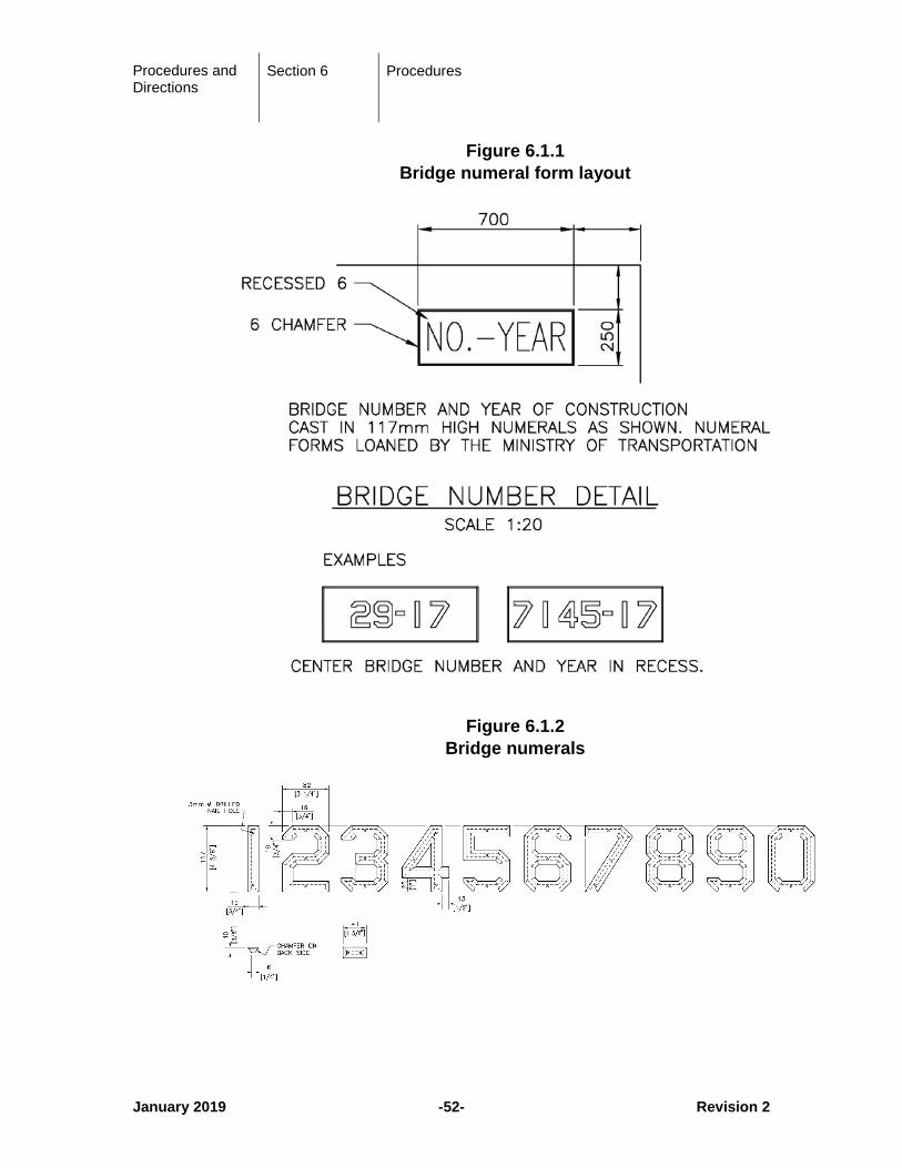
The bridge numeral forms shall be placed on the structure in general accordance with Figure 6.1.1.
Procedures and Directions
Section 6 Procedures
January 2019 -52- Revision 2
Figure 6.1.1 Bridge numeral form layout
Figure 6.1.2 Bridge numerals
Procedures and Directions
Section 6 Procedures
September 2016 -53- Revision 2
6.2 Bridge Standards Committee
The Bridge Standards Committee is comprised of Ministry representatives from Headquarters, each Region and selected Area Bridge Managers. This group provides a wide cross-section of bridge engineering, construction and maintenance expertise. The Committee meets annually to review and discuss any additions, deletions or modifications to the Ministry Bridge Standards and Procedures Manual. The group is chaired by the Senior Bridge Standards Engineer.
Any suggestions for revisions to the Bridge Standards documentation may be forwarded to:
Senior Bridge Standards Engineer
4B-940 Blanshard Street Victoria, BC, V8W 3E6 Email: [email protected]
6.3 Girder Haul Guidelines
Girders which require transportation by truck on the Ministry highway system shall be sized in order that the following limits are not exceeded:
● Length: 47.5 m out to out including truck
● Width: 4.4 m
● Weight: 64,000 kg including truck (GVW) **
** Higher GVWs are possible in the following situations:
• Lower Mainland Langley to Horseshoe Bay 80,000 kg
• Designated 85 tonne permit Routes. 85,000 kg
Existing 85 tonne routes are documented in Commercial Transport Manual:
https://www2.gov.bc.ca/gov/content/transportation/vehicle-safety-enforcement/information-education/commercial-transport-procedures
• The project funds the successful evaluation of any required routes for 85 t status.
Procedures and Directions
Section 6 Procedures
August 2007 -54- Revision 1
The design engineer shall determine and verify whether the girder of a particular length and weight can be transported to the bridge site, including consideration of tight corners and switchbacks and compliance with posted load limits on bridges on route.
If particular girders are close to the guidelines or if a slightly larger girder is required, the design engineer should contact representatives of companies specializing in girder transportation to see if limiting weight and length constraints can be met with their particular haul vehicles: Mick Thomas of Davey Cartage at (604) 580 9877, or Bill Sengotta of Rocky Mountain Transport at (250) 542-3116. The approximate limiting constraints for steel girders are the maximum length of 41.5 m or weight of 43,500 kg (for 64,000 GVW).
The approximate limiting constraints for prestressed concrete girders are the maximum length of 39 m or weight of 43,000 kg (for 64,000 kg GVW). Girder weights shall be calculated using concrete densities of 2650 kg/m3 for I-Girders and 2720 kg/m3 for box girders to provide allowance for spread of formwork and higher reinforcing steel densities.
For the transportation of very short heavy sections, trucking companies should be consulted for girder weights that will meet both the bridge overload formula and the permissible maximum GVW.
6.4 Slope Pavement Treatment
6.4.1 General
Slope pavement treatment shall be provided under overpass or underpass bridges to protect the bridge end fill from erosion provide a surface treatment where landscaping is not viable and as an aesthetic treatment for areas under bridges. The need and application of slope pavement treatment will be adjudicated on a site specific basis.
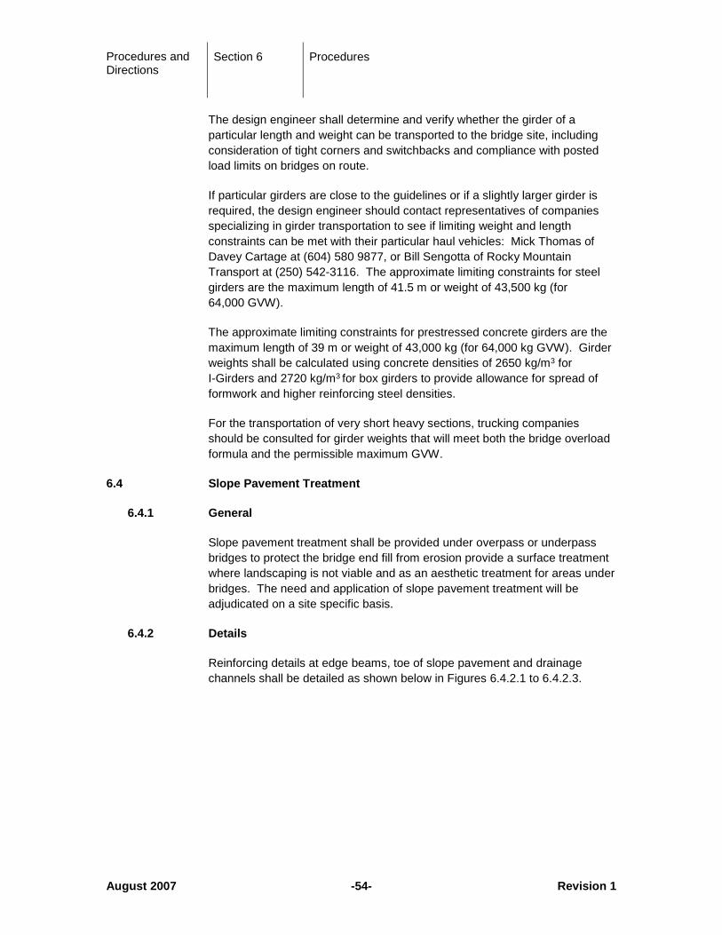
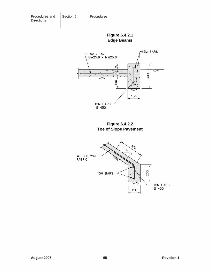
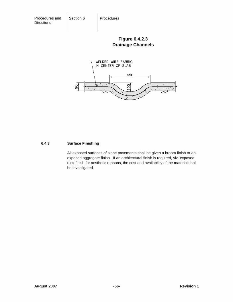
6.4.2 Details
Reinforcing details at edge beams, toe of slope pavement and drainage channels shall be detailed as shown below in Figures 6.4.2.1 to 6.4.2.3.
Procedures and Directions
Section 6 Procedures
August 2007 -55- Revision 1
Figure 6.4.2.1 Edge Beams
Figure 6.4.2.2
Toe of Slope Pavement
Procedures and Directions
Section 6 Procedures
August 2007 -56- Revision 1
Figure 6.4.2.3 Drainage Channels
6.4.3 Surface Finishing
All exposed surfaces of slope pavements shall be given a broom finish or an exposed aggregate finish. If an architectural finish is required, viz. exposed rock finish for aesthetic reasons, the cost and availability of the material shall be investigated.
Procedures and Directions
Section 7 Special Provisions and Appendices
August 2007 -57- Revision 1
7 Special Provisions and Appendices
The Special Provisions are a template of construction specification clauses intended to cover the most common aspects of bridge and structure construction used on Ministry projects. The designer is responsible for selecting the appropriate clauses that augment the design of the bridge or structure and for providing any new clauses or modifications as required to suit the specific project requirements. The text in the Special Provisions template is generally not to be modified other than as allowed by the hidden text within the document to describe project specific attributes.
The Senior Bridge Standards Engineer, with assistance from the Bridge Standards Committee is responsible updating the Special Provisions to ensure that the documentation reflects best practices for bridge construction to ensure a quality and durable product.
The Special Provisions Template is located at the following web site:
https://www2.gov.bc.ca/gov/content/transportation/transportation-infrastructure/engineering-standards-guidelines/structural/standards-procedures/volume-7