bridges for service life beyond 100 years: innovative ... and... · innovative systems, subsystems...
TRANSCRIPT

Bridges for Service Life Beyond 100 Years: Innovative Systems, Subsystems and Components
SHRP 2 | Project R19A
SHRP 2- Project (R19A)
Bridges for Service Life beyond 100 Years: Innovative Systems,
Subsystems, and Components
Principal Investigator: Dr. Atorod Azizinamini, P.E.
Professor and Chairperson
Florida International University
Miami, Florida
Program Officer: Dr. Monica Starnes (2007-2010)
Mark Bush, P.E., PTOE (Jan 2011- Dec 2011)
Jerry DiMaggio (Jan 2012 to present)
Main Product
Design Guide for Bridges for Service Life, hereafter referred to as the
Guide.
Provides systematic and general approach for design
for service life is developed.
Camera ready copy of the Guide was submitted Feb 2013 Should be available by end of March 2013

Research Team Members Florida International University
University of Nebraska
HDR
Attkins
Celik Ozyildirim
KTA
Vector Corrosion
University of Delaware
Georgia Inst. Of Tech
AASHTO T-9 Ralph Oesterle, CTL – Jointless Bridges
Lloryd Sterling – Water Proofing Bridge Deck
Martin Burke – Consultant – Jointless Bridges
Charles Roeder- University of Washington- Bearings
Six (6) Ph.D., students
Three (3) M.S. students
Three (2) Research Associates

Strategy, Technology and Ranking Tables
Concrete Durability Bridge Decks
Substructures Bearings
Fatigue and Fracture
Steel Bridges
Expansion Joints, Joints and Jointless
Structural Steel Protection
Concrete Bridges
Major Categories
Concrete DurabilityConcrete Durability Bridge DecksBridge Decks
SubstructuresSubstructures BearingsBearings
Fatigue and Fracture
Fatigue and Fracture
Steel BridgesSteel Bridges
Expansion Joints, Joints and JointlessExpansion Joints,
Joints and JointlessStructural Steel
ProtectionStructural Steel
Protection
Concrete BridgesConcrete Bridges
Major Categories
Suggested Topics
Categ
ory 1
Categ
ory 2
Categ
ory 3
Suggested Topics
Categ
ory 1
Categ
ory 2
Categ
ory 3
Input of AASHTO Sub-committees
Survey of DOTs
Input from IndustryInput of Individuals Outside the Team
Analysis of NBI Data
Problematic Issues
Input of AASHTO Sub-committeesInput of AASHTO Sub-committees
Survey of DOTsSurvey of DOTs
Input from IndustryInput from IndustryInput of Individuals Outside the Team
Input of Individuals Outside the Team
Analysis of NBI Data
Analysis of NBI Data
Problematic Issues
Chapter 11
Chapter 12
Chapter 13
Stand Alone Guide
Chapter 14
Chapter 15
Chapter 6
Chapter 7
Chapter 8
Chapter 9
Chapter 10
Chapter 1
Chapter 2
Chapter 3
Chapter 4
Chapter 5
Chapter 11Chapter 11
Chapter 12Chapter 12
Chapter 13Chapter 13
Stand Alone Guide
Chapter 14Chapter 14
Chapter 15Chapter 15
Chapter 6Chapter 6
Chapter 7Chapter 7
Chapter 8Chapter 8
Chapter 9Chapter 9
Chapter 10Chapter 10
Chapter 1Chapter 1
Chapter 2Chapter 2
Chapter 3Chapter 3
Chapter 4Chapter 4
Chapter 5Chapter 5
Start
AASHTO Specifications
Design Guide for
“Bridges for Service Life”

Project main product
Design Guide for Bridges for Service
Life

Guide is primarily for bridges with spans of less than 300 ft.
However, Guide provides a frame work
that could be used to address service life design of any span bridges
Review of bridges that have lasted more than 100 years indicates:
1- Maintainable and well maintained over their 100-
year lives due to extreme importance or high capital replacement cost, 2- Originally over-designed
.

Traditional Approaches - Service life of bridges in various codes and an - Direct or indirect and isolated form, specifying the use of certain details or properties such as cover thickness, maximum crack width, concrete compressive strength, etc.

How to accomplish design for service life
- At the design stage - Systematic and comprehensive - Plan should eliminate the surprise
factor for the owner

OBJECTIVES OF THE GUIDE
The main objective of the Guide is to provide information about, and define
procedures for systematically designing for service life and durability for both new and
existing bridges.
GUIDE Approach - Provide body of knowledge to make
decision - Establish array of solutions - Allow incorporating local experiences,
practice and preferences - Let designer and owner select the
optimum solution

Chapters
Design Guide for
“Bridges for Service Life”
General categories of information included in each Chapter 1- Introduction 2- Factors Affecting Service Life 3- Options for Enhancing Service Life 4- Strategy for developing solution for specific problem 5- Management Plan 6- Examples

Guide for Bridges for Life
Sources of Information Being Used
to Develop the Guide
Available information
in AASHTO specifications
Synthesis of state
of the knowledge
Results of R19A
research (about 40%)
Industry inputs
AASHTO and
DOT inputs Input from
other experts
Others, such as
fib C5
Commission

Chapter 1- Design for Service Life: general
Framework Chapter 1-This chapter provides an overview of the
approach used in the Guide for design for service life.
Chapter 1, also describes terminologies used throughout the
guide and various relationships that exist between service
life of bridge element, component, subsystem and system
and bridge design life as used in AASHTO Specifications. It
provides an introduction to the different philosophies used
to predict service life. It is essential to read this chapter
before proceeding with use of the Guide.
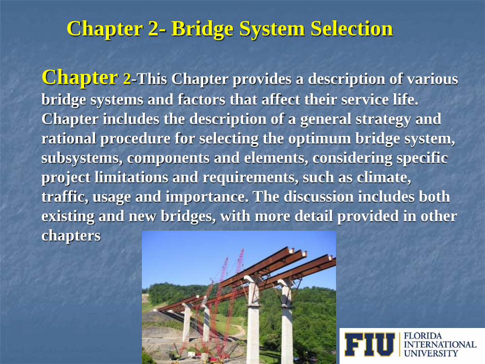
Chapter 2- Bridge System Selection
Chapter 2-This Chapter provides a description of various
bridge systems and factors that affect their service life.
Chapter includes the description of a general strategy and
rational procedure for selecting the optimum bridge system,
subsystems, components and elements, considering specific
project limitations and requirements, such as climate,
traffic, usage and importance. The discussion includes both
existing and new bridges, with more detail provided in other
chapters
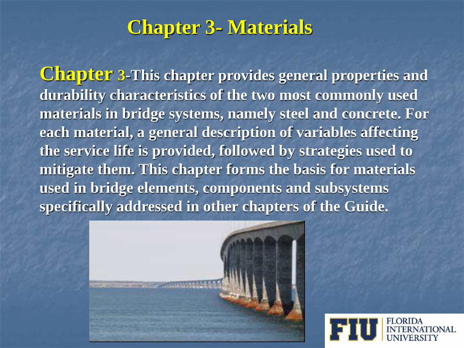
Chapter 3- Materials
Chapter 3-This chapter provides general properties and
durability characteristics of the two most commonly used
materials in bridge systems, namely steel and concrete. For
each material, a general description of variables affecting
the service life is provided, followed by strategies used to
mitigate them. This chapter forms the basis for materials
used in bridge elements, components and subsystems
specifically addressed in other chapters of the Guide.

Chapter 4- Bridge Deck
Chapter 4-This chapter provides descriptions of various
bridge deck types and essential information related to their
service life, such as modes of deterioration and strategies to
mitigate them. The chapter concentrates on cast-in-place
and precast concrete bridge decks.
Chapter 4- Bridge Deck
New Concepts- Self stressing
Waterproofing Manual

Chapter 5- Corrosion Protection of Concrete
Bridges Chapter 5-This chapter provides basic mechanisms
causing corrosion of reinforcement embedded in concrete and strategies for preventing corrosion of reinforcement in concrete bridges
Chloride Contaminated
Concrete
Fe Fe2+ + 2e -
Fe2+ + 2Cl- FeCl2
2Fe(OH)2 + 1/2O2Fe2O3 + 2H2O
2e -
FeCl2 + 2OH- Fe(OH)2 + 2Cl-
2OH-
1/2O2 + H2O + 2e - 2OH-

Chapter 6- Corrosion Protection of Steel
Bridges Chapter 6-This chapter provides descriptions of various
coating systems using paint, galvanizing and metalizing, and descriptions of corrosion resistant steels along with factors affecting their service life. Various options for preventing corrosion of steel bridges and general approaches that could lead to bridge coatings with enhanced service life are presented.
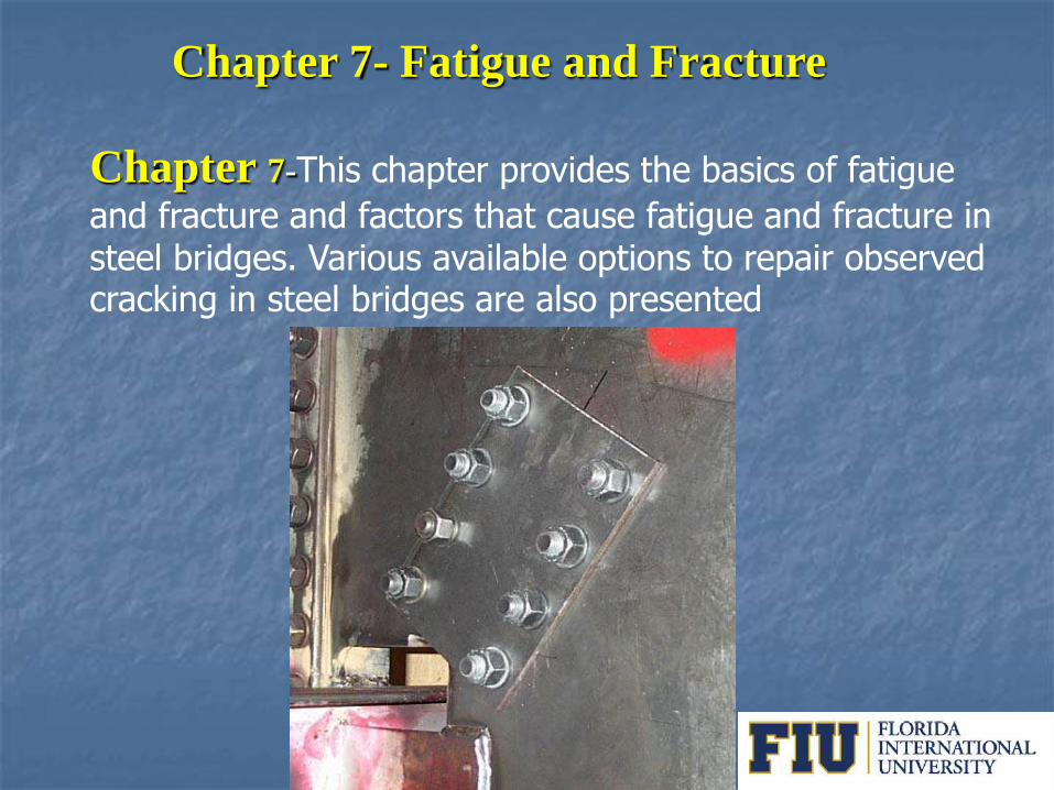
Chapter 7- Fatigue and Fracture
Chapter 7-This chapter provides the basics of fatigue
and fracture and factors that cause fatigue and fracture in steel bridges. Various available options to repair observed cracking in steel bridges are also presented

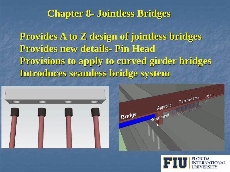
Chapter 8- Jointless Bridges
Chapter 8- This chapter provides descriptions,
advantages and disadvantages of various jointless bridge systems, and provides complete steps for design of jointless integral abutment bridges. This chapter provides design procedures to extend the application of jointless integral bridges to curved girder bridges. This chapter also introduces new details and integral abutment systems, where expansion joints are completely eliminated, even at the end of approach slabs.
Chapter 8- Jointless Bridges
Provides A to Z design of jointless bridges
Provides new details- Pin Head
Provisions to apply to curved girder bridges
Introduces seamless bridge system

0
1
2
3
4
5
6
7
8
9
10
0 50 100 150 200
Dis
p. C
ap
aci
ty (
in)
Axial Load (kips)
HP12x84-Medium Clay
Pinned-Strong
Pinned-Weak
Fixed-StrongFixed-Weak

Bridge Approach
Abutment
Transition Zone
JPCP
Secondary Slab
Small Piles

Chapter 9- Bridge Expansion Devices
Chapter 9- The Guide encourages, eliminating the use of
expansion joints, however, expansion joints may be needed
when the total bridge length exceeds practical limits of
jointless bridges. This chapter provides description of
various expansion joints used in practice, observed modes of
failure for each and potential strategies to mitigate them.

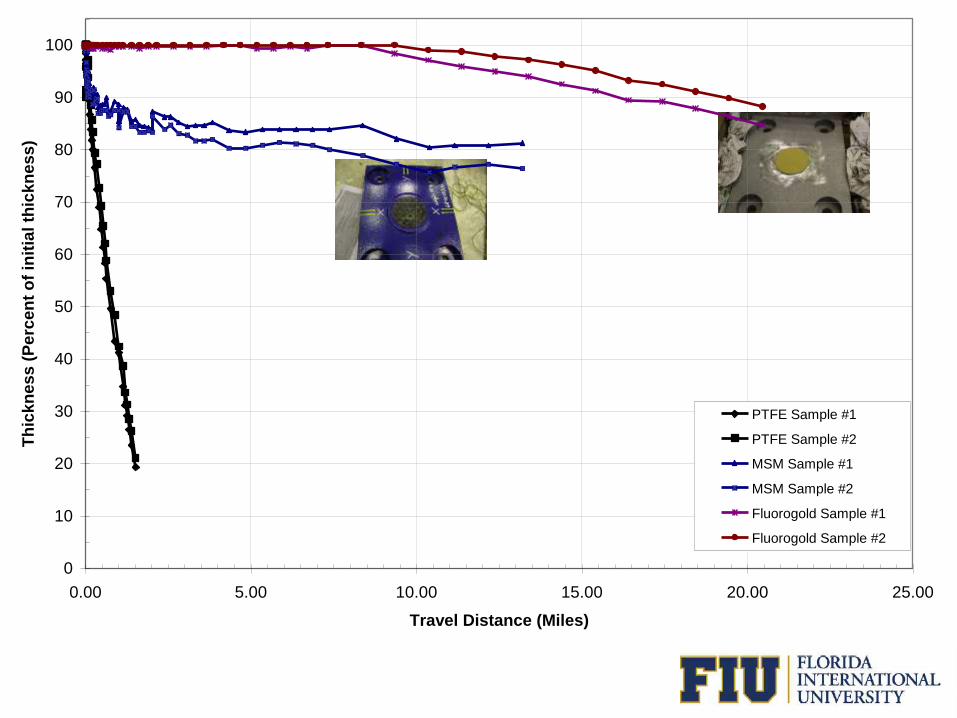
Chapter 10- Bridge Bearings
Chapter 10-This chapter provides descriptions of
various bearing types, and lists factors that affect their service life with strategies to mitigate them. New materials capable of providing long service life for sliding surfaces are introduced as well as deterioration models for sliding surfaces. The Guide emphasizes use of elastomeric bearing pads for long service life.

0
10
20
30
40
50
60
70
80
90
100
0.00 5.00 10.00 15.00 20.00 25.00
Travel Distance (Miles)
Th
ick
ne
ss
(P
erc
en
t o
f in
itia
l th
ick
ne
ss
)
PTFE Sample #1
PTFE Sample #2
MSM Sample #1
MSM Sample #2
Fluorogold Sample #1
Fluorogold Sample #2

0
10
20
30
40
50
60
70
80
90
100
0.00 5.00 10.00 15.00 20.00 25.00
Travel Distance (Miles)
Th
ick
ne
ss
(P
erc
en
t o
f in
itia
l th
ick
ne
ss
)
PTFE Sample #1
PTFE Sample #2
MSM Sample #1
MSM Sample #2
Fluorogold Sample #1
Fluorogold Sample #2
𝑊𝑒𝑎𝑟 𝑅𝑎𝑡𝑒 = 𝐵𝑎𝑠𝑒 𝑊𝑒𝑎𝑟 𝑅𝑎𝑡𝑒 (𝑀𝑎𝑡𝑒𝑟𝑖𝑎𝑙, 𝑃, 𝑉) × 𝐶𝑇 × 𝐶𝐿 Eq. 1
(𝑇𝐷)𝑇𝑟 = 2 × 𝐴 × 𝜃 × 𝐷1 × 𝑛 × 1.33 × 𝐴𝐷𝑇𝑇 𝑆𝐿 × (𝑆𝐿)𝐵 ×365
63360 Eq. 1
(𝑇𝐷)𝐷𝑇 = ∆𝐿𝐷𝑎𝑖𝑙𝑦 × (𝑆𝐿)𝐵 × 365/5280 Eq. 3
(𝑇𝐷)𝑆𝑇 = ∆𝐿𝐴𝑛𝑛𝑢𝑎𝑙 × (𝑆𝐿)𝐵 ×1
5280 Eq. 4
(TD) Demand = (𝑇𝐷)𝑇𝑟 + (𝑇𝐷)𝐷𝑇 + (𝑇𝐷)𝑆𝑇 Eq. 5

Chapter 11- Life Cycle Cost Analysis
Chapter 11-This chapter provides essential information
for incorporating Life Cycle Cost Analysis (LCCA) in bridge system, subsystem, component and element selection. This chapter concentrates on general features and elements of incorporating LCCA in the design process, emphasizing consideration of project costs throughout its service life.
Probability Distribution
of NPV
Uncertainty in
Construction Cost
Uncertainty in Timing
Uncertainty in Repair
Costs

Steps in Design for Service Life
Step 1- Identify the factors that influence the service life of bridge elements, components and subsystems, such as traffic, environmental or internal defects and risk to damage. Step 2- Identify the deterioration and damage mechanism, such as freeze/thaw cycles Step 3- Identify modes of failures and consequences. For instance, the corrosion of reinforcement, causing corrosion induced cracking and loss of strength.

Steps in Design for Service Life
Step 4- Identify suitable approaches for mitigating the failure modes or assessing risk of damage, through life cycle cost analysis. For instance, use of higher performing materials for sliding surfaces in bearings or use of material prone to deterioration at lower initial cost. Step 5- Estimate service life of the bridge element, component or subsystem using Finite or Target Service Life Design approaches. Step 6- Compare the service life of the bridge element, component or subsystem to the service life of the bridge system and develop appropriate maintenance, retrofit and/or replacement plan. Step 7- Develop design, fabrication, construction, operation, maintenance, replacement and management plans for achieving the specified design life for the bridge system.
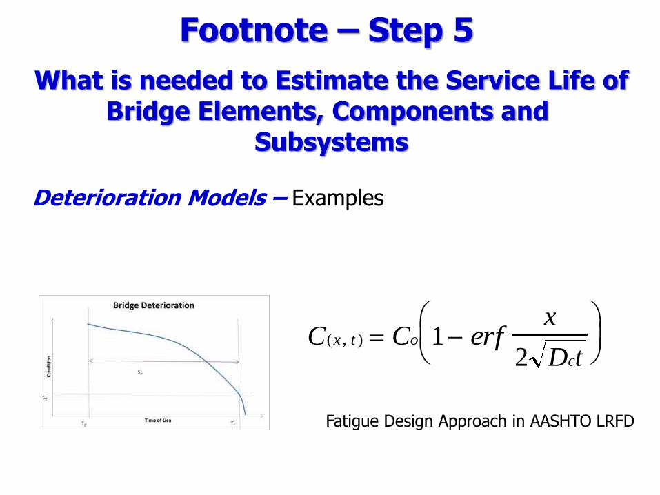
What is needed to Estimate the Service Life of Bridge Elements, Components and
Subsystems
Deterioration Models – Examples
C C erfx
D tx t o
c
( , )
1
2
Fatigue Design Approach in AASHTO LRFD
Footnote – Step 5

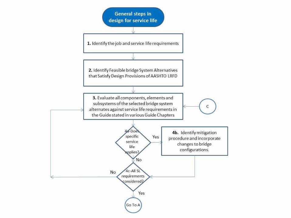
Flow Charts to Use Guide Series of flow charts are provided, within each chapter, that allows an engineer with minimal design experience to navigate through design for service life steps. Next slide shows the main steps, without elaborating on the details
Fault Tree- Identifying factors affecting service life The fault tree is used to systematically identify the factors that can affect service life of a particular bridge element, component, or subsystem.
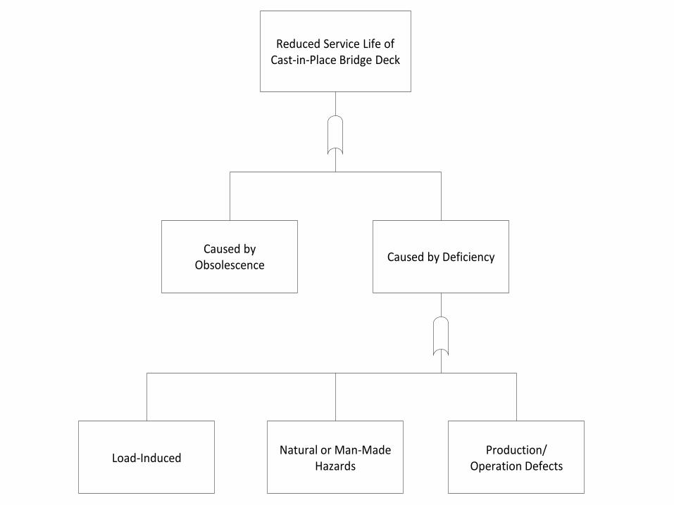
Reduced Service Life of Cast-in-Place Bridge Deck
Caused by DeficiencyCaused by
Obsolescence
Natural or Man-Made Hazards
Load-InducedProduction/
Operation Defects

Load-Induced
WearFatigue
System-Dependent Loads
Differential Shrinkage
System Framing Restraint
Traffic-Induced Loads
ThermalOverload
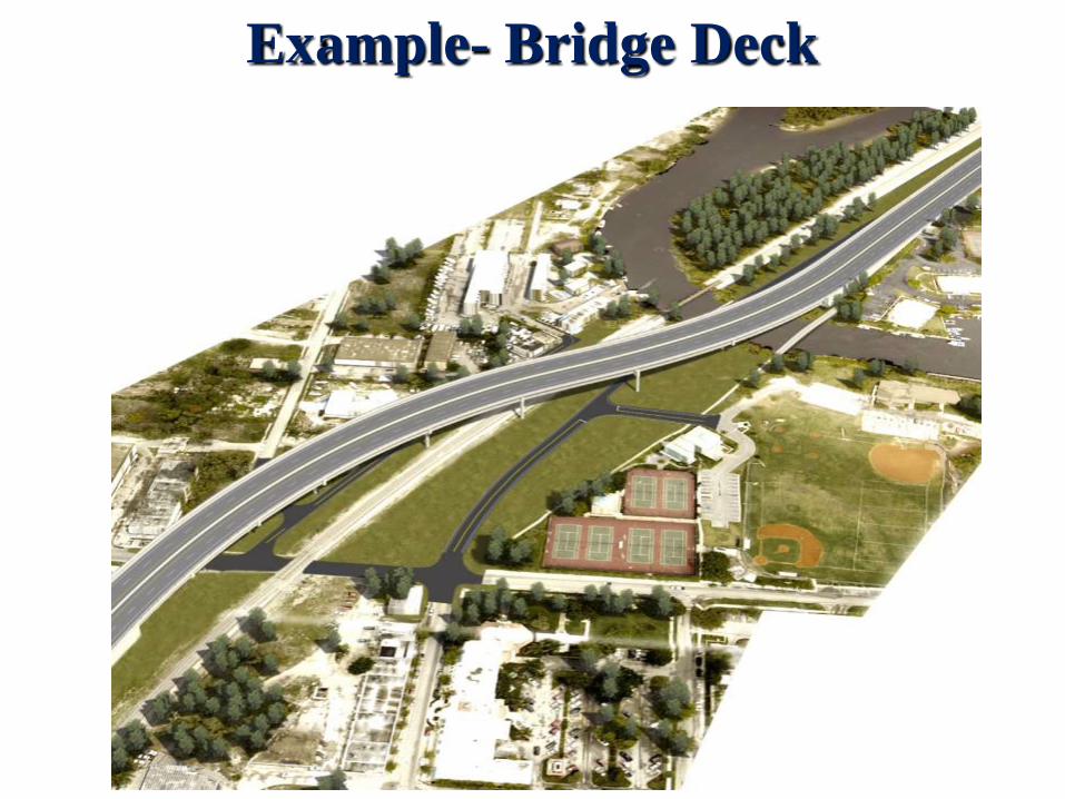
Example- Bridge Deck

1.b: Identify Local Factors Affecting Service Life
2: Identify Feasible Deck Alternatives Satisfying Design Provisions of AASHTO LRFD, Operational, Site and
Bridge System Requirements
1.a: Identify Local Operational and Site Requirements
3: For Each Alternative, Identify Factors Affecting Service Life Following Fault Tree
Go ToA
Bridge Deck System Component Selection Process
Yes
No
6: Identify Maintenance Requirements
5.a: Identify Rehab or Replacement Requirements
Yes
7: Develop Life Cycle Costs
No5: Deck SL ≥ System
TDSL?
8: Add’l. Deck Alternative?
9: Compare Alternatives and Select Deck System
B8.a: Go To Next
Alternative
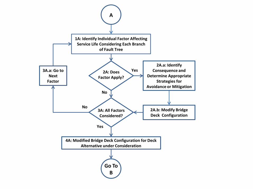
2A.b: Modify Bridge Deck Configuration
A
2A.a: Identify Consequence and
Determine Appropriate Strategies for
Avoidance or Mitigation
1A: Identify Individual Factor Affecting Service Life Considering Each Branch
of Fault Tree
3A.a: Go to Next
Factor
4A: Modified Bridge Deck Configuration for Deck Alternative under Consideration
Go ToB
Yes
No
2A: Does Factor Apply?
Yes
No3A: All Factors Considered?

Operational Category Operational Criteria to Be Specified
Traffic capacity requirements Urban arterial, 4 lanes, 40 mph
Traffic volumes and required capacity 24000 ADT NB and SB
Truck volumes 10%
Special vehicle uses Overload possible
The local environment or man-made hazard category Maintain 2 existing lanes
Mixed use requirements Traffic, pedestrians, bicycle lane
Vehicle loads and special vehicle load requirements
HL 93 with typical legal and permit loads No special construction loads Overload with 20 kip tire loads (HL93 truck configuration) Studded tires used in winter
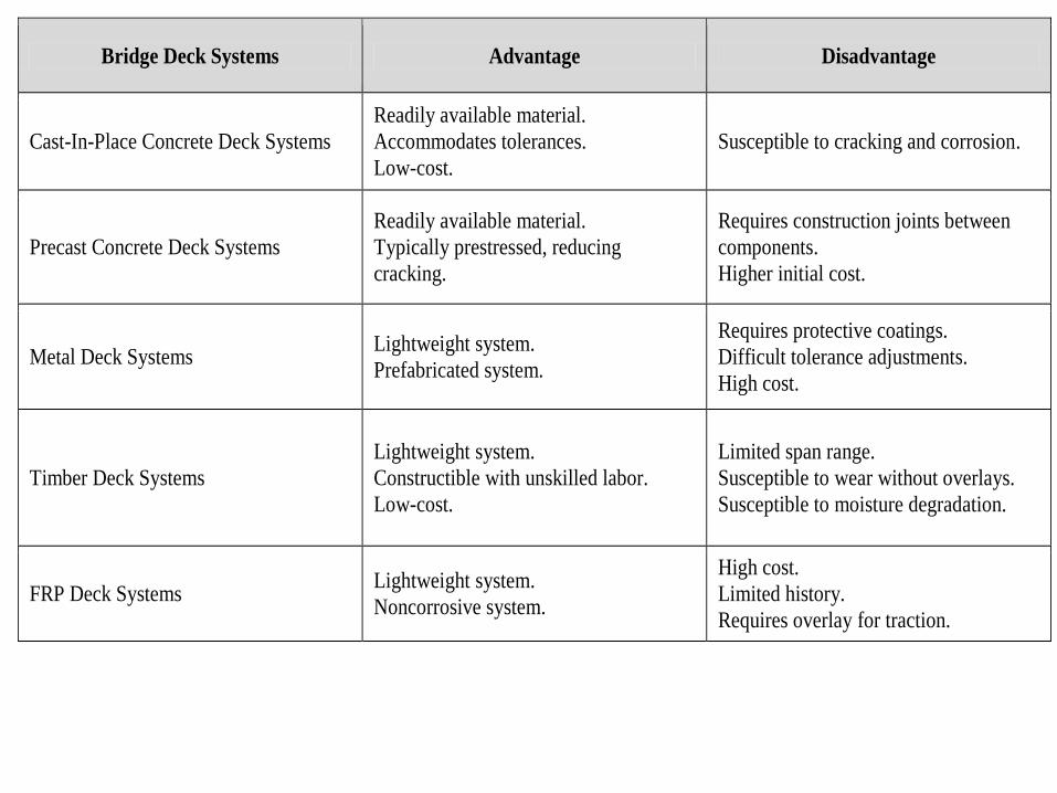
Bridge Deck Systems Advantage Disadvantage
Cast-In-Place Concrete Deck Systems
Readily available material.
Accommodates tolerances.
Low-cost.
Susceptible to cracking and corrosion.
Precast Concrete Deck Systems
Readily available material.
Typically prestressed, reducing
cracking.
Requires construction joints between
components.
Higher initial cost.
Metal Deck Systems Lightweight system.
Prefabricated system.
Requires protective coatings.
Difficult tolerance adjustments.
High cost.
Timber Deck Systems
Lightweight system.
Constructible with unskilled labor.
Low-cost.
Limited span range.
Susceptible to wear without overlays.
Susceptible to moisture degradation.
FRP Deck Systems Lightweight system.
Noncorrosive system.
High cost.
Limited history.
Requires overlay for traction.


Service Life
Issue
Corresponding Job
Requirements Section Mitigating Strategy Advantage Disadvantage
Overload
HL93 with 20 kip
wheel load, applied
once a month
5.3.2.1.1.2 Increase deck thickness Minimizes cracking Adds weight to bridge structure,
increases cost
Minimize bar spacing for given
amount of steel Improves crack control More labor to install and higher cost
Fatigue 24000 ADT NB and SB
and 10% truck volume 5.3.2.1.1.1 Design per LRFD Specifications
Minimizes possibility of
reinforcement failure May increase area of steel
Wear and
Abrasion
Studded tires on high
level of service bridge 5.3.2.1.1.3
Implement concrete mix design
strategies Identified in Chapter 3 Identified in Chapter 3
Implement membranes and
overlays
Protects surface from direct contact
with tires
Requires periodic rehabilitation every
10 to 20 years
System
Framing
Restraint
Deck shrinkage
restraint from shear
studs
5.3.2.1.2.3 Develop accurate system model Identifies design criteria for
establishing stresses
Restraining force may cause cracking
in deck. Refer to Chapter 8.
Differential
Shrinkage
Use low modulus concrete mix
design for composite decks
Allows additional strain to be
accommodated up to cracking stress
Typically lower in strength and may
be subject to wear and abrasion
Use high creep concrete mix
designed for composite decks Reduces locked‐in stresses
Uncommon mix design. Difficult to
assess stress relief
Develop composite action after
concrete has hardened
Allows slippage between deck and
supporting members, minimizing
locked-in stresses
Little experience with experimental
systems. Friction reduction difficult
to assess. Introduces numerous
construction joints. Grout integrity
issues in closed void systems.
Use precast deck panels
Allows slippage between deck and
supporting members, minimizing
locked-in stresses
Introduces numerous construction
joints
Reactive
Ingredients—
ASR/ACR
Local aggregates are
reactive 5.3.2.2.4.1
Use materials and mix designs that
are not sensitive to aggregate Refer to Chapter 3 Refer to Chapter 3
Coastal
Climate—
Humidity
RH average 70% 5.3.2.2.2.2 Use materials that are not sensitive
to moisture content Refer to Chapter 3 Refer to Chapter 3
Thermal
Climate—
Freeze/Thaw
Multiple cycles of
freeze/thaw expected 5.3.2.2.1.2
Refer to Chapter 3 for strategies
relating to freeze/thaw
Refer to Chapter 3 for strategies
relating to freeze/thaw
Refer to Chapter 3 for strategies
relating to freeze/thaw

Overload Fatigue Wear System
Restraint
Differential
Shrinkage Deicing
Freeze/
Thaw Salt spray Humidity ASR/ACR
Increase
Deck
Thinness
Design per
AASHTO
Concrete
mix
Accurate
modeling
during
analysis of
the system
Concrete mix—
Use mix with
low modulus
Impermeable
Concrete
Concrete
mix—
air content
Stainless
steel
Use
aggregate
that are not
sensitive to
humidity
Concrete
mix non-
reactive
aggregate
Membrane
and overlay Stainless Steel
Stay in
place metal
deck to
protect
bottom
Increase
thickness
Specify non-
chloride based
deicing
Deck
bottom
sealer and
top
membrane
Membrane and
Overlay

Before Design
for Service Life
Alt. 1
Good Mix
Alt. 2
Stainless steel

Alt. 3
Large
cover
Alt. 4
Membrane
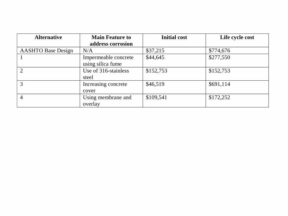
Alternative Main Feature to
address corrosion
Initial cost Life cycle cost
AASHTO Base Design N/A $37,215 $774,676
1 Impermeable concrete
using silica fume
$44,645 $277,550
2 Use of 316-stainless
steel
$152,753 $152,753
3 Increasing concrete
cover
$46,519 $691,114
4 Using membrane and
overlay
$109,541 $172,252

Camera ready copy of the Guide was submitted Feb 2013 Should be available by end of March 2013
Atorod Azizinamini [email protected]
402-770-6210