brightspark easy-cap - british cycle · pdf filemagneto's spark energy in the event that...
TRANSCRIPT

CONVERTING THE ARMATURE
OF A ROTATING-COIL MAGNETO
TO ACCEPT THE
BRIGHTSPARK EASY-CAP (The ‘Condensectomy’)
© 2012 Brightspark Magnetos Limited

1
The Condensectomy The aims of a 'condensectomy' are:
• to take the condenser that is buried in the armature out of circuit, and possibly remove it completely; • to maintain the connection of the 'earth' side of the low-tension winding to the body of the armature; and • to maintain the connection of the 'live' side of the LT winding to the live contact breaker point.
Then, when an EasyCap is fitted to the contact breaker assembly, the whole magneto can function as intended, without the old condenser interfering with the operation.
A number of people have mentioned that if the old condenser has failed completely open circuit, then there is no need to disconnect it. That is true. However, condensers commonly fail in other ways, and it is nigh on impossible to tell whether a condenser has failed open circuit without disconnecting it from the LT winding. Having disconnected it, there's no point in reconnecting it again.
In this booklet, we have set out step-by-step instructions on how to perform a condensectomy on a Lucas K1F, K2F, KVF or N1 magneto or an MO1 or MN2 magdyno. There are a number of procedures involved, as listed below.
Procedure
• Removing the magneto from the machine ········································································ 1 • Removing the magneto armature ·················································································· 2 • Choosing whether to perform the condensectomy······························································· 3
by either: o the 'quick snip' procedure (often not possible) ························································ 4 o or the 'complete works' procedure ······································································ 4
• Reassembling the magneto including fitting an EasyCap ···················································· 15 • Reinstalling the magneto on the machine ······································································· 18
Removing the magneto from the machine Tools required
• If driven by a fixed pinion or sprocket, a suitable puller for removing it • Possibly one or more specially adapted tools for removing the
nuts/screws securing the magneto's mounting flange or base to the engine
Procedure
Remove the magneto from the machine following the instructions in your machine's service manual.
Tips:
If fitted with an automatic timing device (ATD) for advance and retard, undoing the ATD retaining screw more than a few turns should engage its self-extract mechanism, and a further turn of the retaining screw should release the taper.
If fitted with a fixed drive pinion/sprocket, a puller will be required. With some pinions/sprockets, a sleeve of the puller is screwed into the pinion/sprocket, and an extractor screw is then tightened against the end of the magneto drive shaft to release the taper. With others, a universal two-legged puller can be employed, or there may be provision for attaching a bridge puller. Resist the temptation to crowbar the pinion-sprocket off by levering against any mating surfaces of the timing chest.
With magdynos, it is, of course, also necessary to remove the dynamo and its drive train.
Some of fixing nuts/screws may be difficult to access and specially adapted tools may be required. If in doubt and your service manual doesn't help, ask on the appropriate web forum for your machine.

2
Removing the magneto armature Remove the HT pickup(s) and contact breaker end cover.
Be careful not to lose the pick-up brush(es).
With the K2F magneto in the picture, the pick-ups are retained by pivoting spring blades. Other types of pick-up may be held by a pair of screws.
The end cover may be retained by a pair of nuts (as in the example), a pivoting spring blade, or by a large ring screw-threaded onto the magneto body.
Remove the CB assembly.
For ring-cam instruments:
Release the contact breaker centre screw using a 4BA or 1/4"AF nut driver or socket. This will allow removal of the contact breaker assembly as a unit. With screw undone, wiggling it will always free the taper with its integral key. The assembly in the picture is an original Lucas brass one (to be contrasted with later Lucas steel ones and more recent steel pattern ones).
Some brass backplates have an auxiliary earth brush on their rear face.
For face-cam instruments:
Undo the screw holding the moving point and remove the point. This gives access to the centre screw, which needs to be removed after straightening the locking tab washer. The CB assembly can then be withdrawn.
Be careful that the points tappet does not fall out.
Remove the safety screws.
The safety screw(s), if fitted, lie in the same transverse plane as the pick-ups.
Many twin magnetos have two safety screws opposite each other. Many single magnetos have a single safety screw. Some don't have any safety screws.
The safety screws are there to provide a safe route to earth for the magneto's spark energy in the event that the normal path (via the pick-up, HT cable and sparking plug) is interrupted.
ANY SAFETY SCREWS MUST BE REMOVED BEFORE PROCEEDING FURTHER, otherwise they will interfere with, and probably break, the slip ring when withdrawing the armature from the magneto's body.
Remove the earth brush.
The earth brush connects the armature body (and thus the earth end of the HT coil) to the magneto housing (and thus the engine) to provide a return path for the sparking plug current. The earth brush assembly comprises a carbon brush, spring, special hollow screw and usually a fibre washer. Simply unscrew it.
On some magnetos, the earth brush is sometimes hidden beneath the name plate.

3
Remove the end housing.
The housing for the cam and CB-end bearing is removed by undoing the two, three or four screws holding it in place. One of the screws may also double-up as the mounting post for the spring blade that held the CB end cover in place.
Note, and retain, any large brass shims (two of which are shown in the picture).
The outer race of the CB-end bearing should be firmly fixed in the end housing. However, the insulator between the outer race and the housing may have
disintegrated, leaving the race loose. In that case, the insulator will need replacing.
Remove the armature from the main housing.
The armature can now simply be tipped out of the housing. The inner race, cage and balls of the drive-end bearing should come with it, but the outer race of the drive-end bearing should remain in the housing.
Again, the insulator between the outer race and the housing may have disintegrated, leaving the race loose, so that it, and the oil seal, may fall out. In that case, the insulator will need replacing. In any case, having stripped the magneto this far, it is prudent to replace the insulator for the drive-end bearing and the oil seal (if provided).
Choosing between the 'Quick Snip' and the 'Complete Works' condensectomy The 'quick snip' procedure entails electrically disconnecting the original condenser without disassembling the armature, and leaving it in place buried in the armature. By comparison, the 'complete works' entails disassembling the armature.
If you need to disassemble the armature to have the bobbin rewound, then you should do a 'complete works' condensectomy.
In the case of the MO1, MN2 and N1 instruments, the 'quick snip' procedure is not possible, and you'll need to perform the complete works.
In the case of a Lucas K1F, K2F or KVF instrument:
The quick snip isn't always possible, but if it is then you should try it in preference to the complete works. With the complete works, there is probably a greater risk of damaging the wires where they come out of the bobbin necessitating a rewind.
Hold the armature with the drive-end in your left hand, the CB-end in your right hand, and the HT wire that goes from the bobbin into the boss on the slip ring furthest away from you (hidden at the rear). At the top of the gap between the bobbin and the brass drive-end end-piece, you should see a wire sheath coming out of the end of the bobbin. There are two wires inside the sheath, and they are connected to the live side of the existing condenser. You may be able to see the condenser, or it may be potted in a lump of resin. Ask yourself: Have I got the tools and is there enough room so that I can:
• disconnect the wires from the condenser or snip through the sheath, • ensure that the disconnected wires remain electrically connected to each other and solder them if
necessary, and • insulate the disconnected ends so that they don't make electrical contact with anything else?
If the answer is "yes", you can try the quick snip. Otherwise, you'll need to perform the complete works.

4
The 'Quick Snip' condensectomy Special tools/materials required
• Soldering iron (50W preferably) and solder • Adhesive-lined heat-shrink sleeving • Heat gun or other suitable heat source for shrinking the sleeving • Fine long-nosed pliers and/or fine side-cutters
Procedure
In the case of a Lucas K1F, K2F or KVF instrument, place the armature on the bench or in a vice with soft jaws with the drive-end to the left, the CB-end to the right, and the HT wire that goes from the bobbin into the boss on the slip ring furthest away from you (hidden underneath).
At the top of the gap between the bobbin and the brass drive-end end-piece, you should see a wire sheath coming out of the end of the bobbin. There are two wires inside the sheath, and they are connected to the live side of the existing condenser. You may be able to see the condenser, or it may be potted in a lump of resin.
If you can get at the soldered connection to the condenser:
• Unsolder the wires from the condenser. A 50W soldering iron seems best, and a pair of fine long-nosed pliers may help.
• Twist the ends of the wires together and solder them together.
If, however, the wire sheath disappears into a lump of resin:
• Snip the sheath with a pair of fine side-cutters as close to the resin lump as possible.
• Cut back the sheath by about 1/4" to expose the ends of the two wires inside.
• Remove any insulation from the exposed ends of the two wires.
• Twist the ends of the wires together and solder them together.
Now fit a layer of heat-shrink insulation sleeve, preferably adhesive-lined, so as to insulate the ends of the wires from everything else.
Poke the wires back into the space between the drive-end end-piece and the bobbin, and if possible tuck them in so that there is no risk of them flying out again as the armature rotates.
That completes the 'quick snip.'
If it turned out that there there wasn't enough room to perform all of the above steps, then you will now need to disassemble the armature as described in the 'complete works' section.
The 'Complete Works' condensectomy Overview of procedure
We've tried to provide a lot of detail on this set of pages so that you can be sure of what you are doing. The procedure differs depending on whether the slip ring is at the contact-breaker end or the slip-ring end of the armature. In summary the procedure is:

5
Armatures with slip ring at contact breaker end (e.g. K1F, K2F & KVF)
Armatures with slip ring at drive end (e.g. MO1, N1 & MN2)
• Remove inner race of bearing at the CB end, possibly some shims, the oil flinger disc and the slip ring.
• Undo the two long screws holding the armature together, and ease the end piece of the armature at the drive end away from the bobbin to reveal the old condenser.
• Remove inner race of bearing at the drive end, possibly some shims, the oil flinger disc and the slip ring.
• Undo the two long screws holding the armature together, and separate the end piece of the armature at the CB end from the bobbin to reveal the old condenser.
• Electrically disconnect the condenser and remove it, while
o maintaining the connection of the earth end of the LT winding to the drive-end end-piece, and
o maintaining the connection of the live end of the LT winding to the link wire that passes through the bobbin to the nut for the CB centre screw.
• If the old condenser is an original Lucas item:
o Electrically disconnect and isolate the earth side of the condenser,
o connect the earth end of the LT winding to the CB-end end-piece and
o maintain the connection of the live end of the LT winding through the can of the old condenser to the integral nut for the CB centre screw.
• Otherwise:
o Electrically disconnect the old condenser and remove it,
o maintain the connection of the earth end of the LT winding to the CB-end end-piece,
o maintain some form of nut for the CB centre screw, and
o maintain the connection of the live end of the LT winding to the nut for the CB centre screw.
• Reassemble everything and check the straightness of the armature.
The 'Complete Works' condensectomy - splitting the armature
Special tools/materials required
• The Brightspark Toolpack (available for hire from us for the K-series mags) or other suitable pullers for the slip ring and the inner race of the bearing next to the slip ring.
Procedure
Please note that the pictures below show the armature of a Lucas K1F, K2F or KVF magneto, which has the slip ring at the CB end and the condenser at the drive end. For MO1, MN2 and N1 instruments, the slip ring and condenser are at the opposite ends.
6
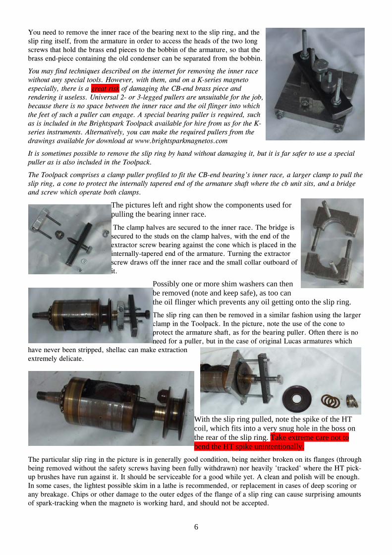
You need to remove the inner race of the bearing next to the slip ring, and the slip ring itself, from the armature in order to access the heads of the two long screws that hold the brass end pieces to the bobbin of the armature, so that the brass end-piece containing the old condenser can be separated from the bobbin.
You may find techniques described on the internet for removing the inner race without any special tools. However, with them, and on a K-series magneto especially, there is a great risk of damaging the CB-end brass piece and rendering it useless. Universal 2- or 3-legged pullers are unsuitable for the job, because there is no space between the inner race and the oil flinger into which the feet of such a puller can engage. A special bearing puller is required, such as is included in the Brightspark Toolpack available for hire from us for the K-series instruments. Alternatively, you can make the required pullers from the drawings available for download at www.brightsparkmagnetos.com
It is sometimes possible to remove the slip ring by hand without damaging it, but it is far safer to use a special puller as is also included in the Toolpack.
The Toolpack comprises a clamp puller profiled to fit the CB-end bearing's inner race, a larger clamp to pull the slip ring, a cone to protect the internally tapered end of the armature shaft where the cb unit sits, and a bridge and screw which operate both clamps.
The pictures left and right show the components used for pulling the bearing inner race.
The clamp halves are secured to the inner race. The bridge is secured to the studs on the clamp halves, with the end of the extractor screw bearing against the cone which is placed in the internally-tapered end of the armature. Turning the extractor screw draws off the inner race and the small collar outboard of it.
Possibly one or more shim washers can then be removed (note and keep safe), as too can the oil flinger which prevents any oil getting onto the slip ring. The slip ring can then be removed in a similar fashion using the larger clamp in the Toolpack. In the picture, note the use of the cone to protect the armature shaft, as for the bearing puller. Often there is no need for a puller, but in the case of original Lucas armatures which
have never been stripped, shellac can make extraction extremely delicate.
With the slip ring pulled, note the spike of the HT coil, which fits into a very snug hole in the boss on the rear of the slip ring. Take extreme care not to bend the HT spike unintentionally.
The particular slip ring in the picture is in generally good condition, being neither broken on its flanges (through being removed without the safety screws having been fully withdrawn) nor heavily 'tracked' where the HT pick-up brushes have run against it. It should be serviceable for a good while yet. A clean and polish will be enough. In some cases, the lightest possible skim in a lathe is recommended, or replacement in cases of deep scoring or any breakage. Chips or other damage to the outer edges of the flange of a slip ring can cause surprising amounts of spark-tracking when the magneto is working hard, and should not be accepted.

7
Unscrew the two through-screws which hold the brass ends of the armature to the central 'bobbin' - the laminated core around which the low and high tension windings and their insulation are laid. Once you have removed the screws, it is a good idea to put the slip ring temporarily back in place so as to protect the HT spike.
Before going any further, scribe or punch corresponding marks on the bobbin and on the drive-end brass end-piece (but not on the track for the earth brush) so that your can put them back together, later on, the same way round.
Also, if you have an ohmmeter or multimeter, measure and make a note of (a) the LT resistance between the earth brush track and the nut for the CB
centre screw (hidden between the bobbin and the CB-end brass end-piece) and (b) the HT resistance between the earth brush track and the HT spike. You should get readings of about 0.6 Ohms and 5000 Ohms. Anything vastly different from these figures probably indicates that the bobbin needs rewinding, although a lower figure for the LT resistance could be a result of the old capacitor providing a short circuit. Then, the brass end-piece containing the condenser needs to be gently pulled from the bobbin. At this stage you do not need to separate them completely, just by about 5/16" (8mm).
Don't try to separate the other end-piece from the bobbin - all being well, it can be left undisturbed.
For K1F, K2F and KVF magnetos:
The drive-end brass end-piece and the bobbin are also connected by two dowel pins, which are often quite tight.
Resist the urge to hold the drive-end brass end-piece in the vice. You can, however, place a spare 3/8" BSF nut (or an interlocked pair of nuts) on the drive shaft, clamp in the vice, and then try wiggling and pulling the bobbin by hand.
Also, resist the urge to use any significant crowbarring action against the large diameter edge of the drive-end brass end-piece - it is all too easy to distort or damage it and the track for the earth brush.
It is sometimes possible to start the separating movement by screwing the long 2BA through-screws the wrong way round into the drive-end brass end-piece (i.e. from the drive end) and inserting something into the gap between the end piece and the bobbin to prevent the screws passing into their holes in the bobbin.
For MO1, MN2 and N1 instruments:
Dowel pins are not usually provided between the bobbin and the CB-end end-piece containing the condenser, and so things are usually a lot easier.
The 'Complete Works' condensectomy - reconfiguring the K1F, K2F & KVF
Special tools/materials required
• Soldering iron (50W preferably) and solder
• Adhesive-lined heat-shrink sleeving, and a heat gun or other suitable heat source for shrinking the sleeving
• Possibly a small solder tag

8
Procedure - overview
Having eased the drive-end end-piece away from the bobbin, you will be able to see whether the armature is fitted with an original Lucas condenser (picture top right) or with a more modern device which is usually potted in resin. The procedures to be adopted are roughly similar for both and summarised by the following schematics.
IF FITTED WITH ORIGINALLUCAS CONDENSER
Slip ring
Drive-endend-piece
Bobbin
Contact breakerassembly
Points
Centre-screw
Lucas condenser andmounting bracket
Screw
CB-endend-piece
HT spike
LT winding live endLT live link wire
LT windingearth end
Nut for centre screwand insulated mounting
Screw
LT winding live endLT live link wire
LT windingearth end
Solder tag
Heat-shrink
New EasyCap
Earth wire connected todrive-end end-piece bysolder tag and screw
Originalcondenserremoved
Two LT live wires solderedtogether and insulated with
heat-shrink sleeving
BEFORE AFTER
IF FITTED WITH POTTEDNON-ORIGINAL CONDENSER
Slip ring
Drive-endend-piece
Bobbin
Contact breakerassembly
Points
Centre-screw
CB-endend-piece
HT spike
LT winding live endLT live link wire
LT windingearth end
Nut for centre screwand insulated mounting
Screw
LT winding live endLT live link wire
LT windingearth end
Solder tag
Heat-shrink
New EasyCap
Earth wire connected todrive-end end-piece bysolder tag and screw
Resin and originalcondenser removed
Two LT live wires solderedtogether and insulated with
heat-shrink sleeving
CondenserSolder tagand screw
Resin
AFTERBEFORE

9
Procedure - detail
With the armature held in a vice as in the picture to the left, i.e. with the HT spike nearest you, you should see a wire in a sheath coming out of the left-hand side of the lower end of the bobbin. This is the common earth of the HT and LT windings.
You may be able to see where it is connected to earth, for example by being soldered to the metal casing of an original Lucas condenser or its metal mounting bracket, or to a solder tag connected to the brass end-piece. If so, unsolder it. A decent
soldering iron, say 50W, is needed to get the joints to part. Try to concentrate the heat on the joint. Steady hands are needed, as the coil and the wires leading from it won't respond well to excess heat. Once the solder is molten, you may
need to wiggle to wire with a pair of long-nosed pliers in order to free it. But be careful not to break the earth wire near its exit point from the bobbin. If you do break it there, the bobbin will need to be rewound.
If a replacement condenser has previously been fitted, it may be potted in resin, and an earth terminal post may be sticking out of the resin with the earth wire of the bobbin soldered to it, as in the picture to the right. In this case, unsolder the earth wire from the post.
Alternatively, the earth wire may disappear into the resin. If you can carefully excavate into the resin with a fine chisel or punch to reach the place where the wire is soldered, so much the better, and then unsolder it. As a last resort, you may need to snip the wire, using a pair of fine side-cutters, but snip it as far away from the bobbin as possible to leave the maximum amount of wire attached to the bobbin.
With the armature rotated 180 degrees from its previous position as shown in the picture to the left, i.e. with the HT spike away from you, you should see a sheath coming out of the left-hand side of the lower end of the bobbin. This sheath should contain two wires. One is the live end of the LT winding. The other is the link wire up to the nut for the CB centre screw at the other end of the armature. These two wires should be connected to one side of the existing condenser. You need to disconnect them, preferably by unsoldering but if necessary by snipping as far away from the bobbin as possible, in the manner described in the
previous section.
Having disconnected the wires, you can now separate the drive-end end-piece completely from the remainder of the armature.
10
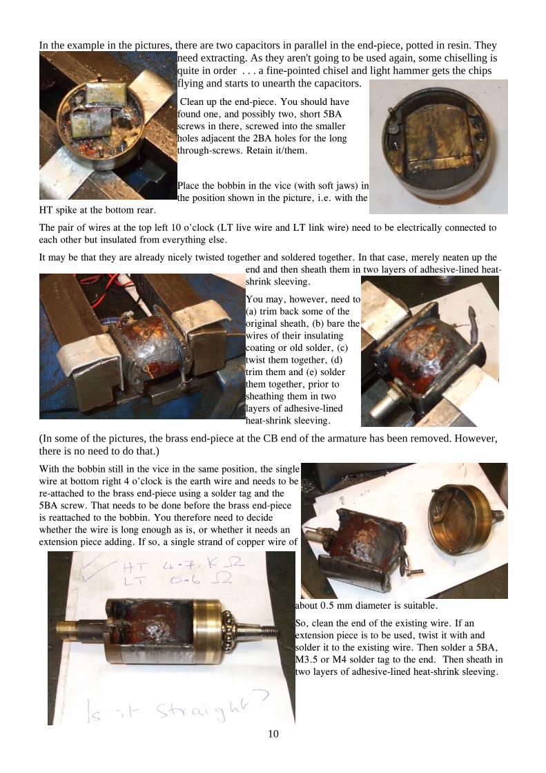
In the example in the pictures, there are two capacitors in parallel in the end-piece, potted in resin. They need extracting. As they aren't going to be used again, some chiselling is quite in order . . . a fine-pointed chisel and light hammer gets the chips flying and starts to unearth the capacitors.
Clean up the end-piece. You should have found one, and possibly two, short 5BA screws in there, screwed into the smaller holes adjacent the 2BA holes for the long through-screws. Retain it/them.
Place the bobbin in the vice (with soft jaws) in the position shown in the picture, i.e. with the
HT spike at the bottom rear.
The pair of wires at the top left 10 o'clock (LT live wire and LT link wire) need to be electrically connected to each other but insulated from everything else.
It may be that they are already nicely twisted together and soldered together. In that case, merely neaten up the end and then sheath them in two layers of adhesive-lined heat-shrink sleeving.
You may, however, need to (a) trim back some of the original sheath, (b) bare the wires of their insulating coating or old solder, (c) twist them together, (d) trim them and (e) solder them together, prior to sheathing them in two layers of adhesive-lined heat-shrink sleeving.
(In some of the pictures, the brass end-piece at the CB end of the armature has been removed. However, there is no need to do that.) With the bobbin still in the vice in the same position, the single wire at bottom right 4 o'clock is the earth wire and needs to be re-attached to the brass end-piece using a solder tag and the 5BA screw. That needs to be done before the brass end-piece is reattached to the bobbin. You therefore need to decide whether the wire is long enough as is, or whether it needs an extension piece adding. If so, a single strand of copper wire of
about 0.5 mm diameter is suitable.
So, clean the end of the existing wire. If an extension piece is to be used, twist it with and solder it to the existing wire. Then solder a 5BA, M3.5 or M4 solder tag to the end. Then sheath in two layers of adhesive-lined heat-shrink sleeving.

11
Now, using the scribe marks you made earlier, work out which of the two 5BA holes in the brass end-piece is going to have the earth wire connected to it, and block the other hole with a spare 5BA screw, silicone or other suitable material. This will prevent any grease from the drive-end bearing getting into the interior of the armature through the hole.
Now attach the earth wire's solder tag to the remaining 5BA hole in the brass end-piece, taking care not to stress the wire too much, and then reassemble the drive-end end-piece with the bobbin, and refit the two long through-screws. Tighten them fully and then release them slightly.
You can now measure the LT and HT resistances again and check whether they are unchanged from the figures you obtained earlier. Make a note of the HT resistance. The 'Complete Works' condensectomy - reconfiguring the MO1, MN2 and N1 Special tools/materials required
• Soldering iron (50W preferably) and solder • Adhesive-lined heat-shrink sleeving, and a heat gun or other
suitable heat source for shrinking the sleeving • Possibly a small solder tag
Procedure - overview
Having partly separated the drive-end end-piece from the bobbin, you will be able to see whether the armature is fitted with an original Lucas condenser (picture top right) or with a more modern device which is usually potted in resin. The procedures to be adopted are somewhat different.
Before proceeding any further, it is important that you mark the bobbin and the armature end-piece at the CB end so that you will put them back together the same way round. Also, work out and make a note of which of the two wires coming from the bobbin is earth (i.e. going to the bracket/tag screwed to the end piece) and which is live (i.e. going to the tag on the condenser which is not earthed).
Procedure - if fitted with original Lucas condenser
The following 'before-and-after' schematic illustrates what is required.

12
IF FITTED WITH ORIGINAL LUCAS CONDENSERBEFORE AFTER
Slip ring
Drive-endend-piece
Bobbin
Contact breakerassembly
Points
Centre-screw
Live LT wireEarth LT wire
Tail-end end-piece
HTspike
Earthtag
Screw
Earthbracket
LivetagScrew Insulating
clamp plateInsulatingspacer
Integral nut for centre screwinternally connected to liveside of condenser
Lucas condenser
Live LT wireEarth LT wire
ScrewLivetagScrew Insulating
clamp plateInsulatingspacer
New EasyCap
Solder tag
Old condenser'searth bracket removed.
Earth LT wire connected to brass end-piece by solder tag and screw.
No change neededon live side
In detail, you need to unsolder the bobbin wires from the condenser so as to free the end-piece and condenser from the remainder of the armature.
Then remove the condenser from the end-piece by undoing the two small screws, noting how the insulating clamp plate and the insulating strip fit, and which way round the condenser was fitted.
Then tear off the earth bracket and grind or file down the stud to which the earth bracket was attached, as shown in the picture to the left.
Fit the old condenser back into the end-piece, the same way round as before, and
check that the remains of the earth stud will not touch the end-piece, as shown in the picture to the right.
If the integral nut for the centre screw looks rusty (as in the photo at the top of the page), clean it up with a 3BA tap, if available.
Solder a solder tag to the end of the bobbin's earth wire.
Re-solder the bobbin's live wire back onto the live terminal of the condenser, making sure that nothing on the live side can short to the brass of the end-piece or the adjacent condenser fixing screw.
Now screw the solder tag on the earth wire into the position where the old earth bracket used to be, as shown in the picture to the left.
Then reassemble the end-piece with the bobbin, and refit the two long

13
through-screws. Tighten them fully and then release them slightly.
You can now measure the LT and HT resistances again and check whether they are unchanged from the figures you obtained earlier. Make a note of the HT resistance.
Procedure - if fitted with a non-original condenser
The original Lucas condenser also provides the nut for the contact-breaker centre screw. When a non-Lucas condenser was subsequently fitted, some method would have been adopted to provide a nut for the centre screw. Also, the new condenser may well have been potted in resin. It is impossible to provide any detailed instructions without knowing what is there at the moment. However, the following 'before-and-after' schematic illustrates generally what is required.
IF FITTED WITH POTTED NON-ORIGINAL CONDENSERAFTERBEFORE
Live LT wire somehowconnected to 3BA nutEarth LT wire
Points
3BA nut for centre screw, and some means for fixing it in placeinsulated from thebrass end piece
Some means (such assolder tag and screw)
for connecting theearth wire to thebrass end-piece
Slip ring
Drive-endend-piece
Bobbin
Contact breakerassembly
Centre-screw
HTspike
Tail-endend-piece
Condenser somehowconnected between liveand earth and possiblypotted in resin
Earth LT wire
3BA nut for centre screw, fixed in placeinsulated from thebrass end piece
Some means (such assolder tag and screw)
for connecting theearth wire to thebrass end-piece
Live LT wireconnected to 3BA nut
New EasyCap
The old condenser isdisconnected and preferablyremoved, leaving the earthwire connected to the brassend-piece and the live wireconnected to a nut fixed to, but insulated from, the brass
end-piece
In summary, you need to:
1. retain the original method of providing a nut for the CB centre screw, or provide some alternative which is insulated from the brass end-piece;
2. identify which is the earth wire from the bobbin and ensure that it remains connected to the brass end-piece;
3. identify which is the live wire from the bobbin and ensure that it remains connected to the nut for the centre screw without being able to short to the brass end-piece;
4. disconnect at least one of the wires to the previous condenser (and possibly remove it altogether) without affecting connections "2" and "3" above.
Once that has been done, reassemble the end-piece with the bobbin, and refit the two long through-screws. Tighten them fully and then release them slightly.
You can now measure the LT and HT resistances again and check whether they are unchanged from the figures you obtained earlier. Make a note of the HT resistance.

14
The Complete Works' condensectomy - reassembling the armature
Special tools/materials required
• 15mm+ i.d. cylindrical drift (an 11/16"AF 1/2"-drive socket may well do the trick for the K-series instruments)
• Preferably a lathe (or access to one), but you can make do without one
Procedure
The aim now is to re-tighten the two long through-screws with the armature straight. If you have a lathe, it makes the job simple. If you don't but a friend does, speak nicely to them. If you don't have access to a lathe or anything similar, you can try the technique described later.
A potential serious lack of straightness usually arises where the bobbin and brass end-pieces are not a matched set as left the factory together, or where the parts have been distorted through over-zealous use of hammer and crowbar.
If the armature is seriously unstraight, it may result in the bobbin clashing with the magnetic pole pieces in the main housing. If the armature is only slightly out-of-straight, it might cause some vibration, but we'd guess that would be minimal. It might cause an increased wear rate of the bearings, or early breakdown of the bearing insulators. It might also cause an eccentric or swashplate movement of the drive pinion or sprocket. Using the lathe straightening method:-
A. Place the portion of the armature that carries the slip ring in the chuck. Especially in the case of the K-series instruments, take care not to damage the HT spike. Turn the lathe slowly, and check whether the armature seems to be straight. We find there's no need to use a dial gauge or the like.
B. If not straight, set up the toolpost, or something mounted on the toolpost, so that it can smoothly rub again the track for the earth brush without damaging it. Apply a little oil to the earth track. Now turn the lathe and slowly advance the cross-slide until the armature does seem to run straight. Then slowly move the cross-slide back.
C. Now remove the armature from the chuck and tighten the long through-screws slightly.
D. Keep repeating the above steps "A" to "C" until the through-screws are fully tightened.
It may be impossible to achieve a perfect result, but usually a good one is possible. It is often the case that the threaded section for the nut that secures the drive pinion/sprocket is out of line, owing to brutality on the part of owners who lacked the correct tools for removing the drive. This is particularly true on armatures which use all-brass end pieces at that end. If that is the case, there is not much you can do about it, other than try to find a better second-hand armature. If you do not have access to a lathe, you can try using a pair of V-blocks and a dial gauge to check straightness of the armature. Another method involves:
• temporarily refitting the CB-end inner race and balls without the slip-ring in the case of a K1F, K2F or KVF;
• placing the CB housing in the soft jaws of a vice with the outer race uppermost; • temporarily refitting the CB centre screw without the CB assembly and tying a length of string to it; • placing the armature on the CB housing with the string passing though the hole; • tying a heavy weight to the other end of the string; • spinning the armature slowly on the bearing; and • looking at it from the side to see if it wobbles.
Once you are happy with the straightness of the armature, the slip ring now needs to be replaced. It helps if it is not a tight fit on the armature. Therefore ensure that the hole through the slip ring (and also the portion of the armature on which it fits) are clean and clear of any residues of shellac. Also, ensure that the HT spike is clean, but do not remove any metal from it. As the slip ring is slid into position, the HT spike needs to enter the tiny

15
hole at the bottom of the larger hole in the boss on the slip ring. Care needs to be taken. Usually, it helps if the HT spike is not parallel to the armature axis, but is angled slightly towards it, as the slip ring is offered up to it.
After fitting the slip ring, check that the resistance between the brass segment of the slip ring and the body of the armature is the same as the HT resistance you measured previously. If it is significantly higher, then you have a bad connection between the HT spike and the slip ring. It might be possible to cure that by removing the slip ring, squeezing the sides of the HT spike between a pair of pliers so that the wire takes on a very slightly oval cross-section, and then refitting the slip ring. Any problem with refitting may be the result of there previously having been a bad connection, and the slip ring having become burnt inside that tiny hole. If you have any suspicion of that, renew the slip ring. All in all, great care is needed in an attempt to achieve a good connection without buckling the HT spike or, worse still, breaking it so that a rewind of the bobbin is required.
Now replace the oil flinger and any shim washers that were originally on the shaft. If you have a micrometer or slide gauge, it is a good idea to measure and make a note of the thickness of each shim washer.
Now rest the armature, slip-ring up, on the open jaws of a vice. Then choose a cylindrical drift that you will use to drive the inner race of the bearing into position. It needs an internal diameter of just over 15mm. If you have an 11/16"AF 1/2"-drive socket to hand, you may find that it is just the right size for the K-series. Something longer is required for the magdynos. Place the inner race over the end of the shaft and drive it home using your drift, a hammer and moderate taps, trying not to disturb the straightness of the armature. As the upper face of the race becomes level with the end of the armature shaft, be careful that your drift does not damage the brass at the end of the shaft. You will probably be able to tell when the race is fully home from a change in the sound of your taps. Finally, for the K-series instruments, replace the small collar next to the race, using a similar technique as for the race. Then fit the cages and balls to the races at each end of the armature, and the reassembly of the armature is complete.
Reassembling the magneto including fitting an EasyCap Special tools/materials required
• EasyCap capacitor
• Possibly additional shims
Procedure
Place the armature in the main housing and refit the end-housing and the original shims for it if there were any. As the screws approach being tight, check that there is end float and that it does not completely disappear. The acceptable end float is between 0.001" and 0.005".
If there is negative end float, loosen the two screws until there is no end float and no preload, and then use a set of feeler gauges to measure the gap between the end housing and the main housing. You will then need either to obtain/make and fit one or more end-housing shims and/or remove one or more of the shaft shims that you may have fitted earlier. You can use your feeler gauge measurement to calculate the required thickness to achieve the desired end float. End housing shims are available in thicknesses of 0.003" and 0.005".
If there is positive end float, try to assess how much there is. You will then need either to remove one or more end-housing shims and/or add one or more shaft shims so as to correct the end float.
Although the pukka end housing shims are of brass and are still available, we have found that homemade shims of paper/card are perfectly satisfactory. You can download a pattern for a standard K1F/K2F/KVF end housing shim by clicking here. It can be printed out at 100% scale on paper or card, cut out and punched, and there you are.
16
Once you are happy with the end float, remove the armature, check that there aren't any ferrous particles stuck to the magnetic pole pieces in the main housing, apply a high-melting-point grease (such as Castrol 'LM') to the balls of the bearings, reassemble, and fully tighten the screws for the end housing. The armature should spin freely.
Now clean, check the condition of, and replace the earth brush and safety screws and, if appropriate, the manual advance and retard mechanism.
For the ring cam instruments, with the cam ring removed, apply some engine oil to the felt strip in the end housing and, if present, the felt pellet in the ring cam. Then replace the ring cam, ensuring that the notch with the square sides registers with the pin in the cam housing. If manual advance and retard is fitted, also ensure that the fitting at the end of the advance/retard cable registers with the V-shaped notch in the cam ring.
Turning now to the contact-breaker assembly, different procedures are required for the different types of CB assembly.
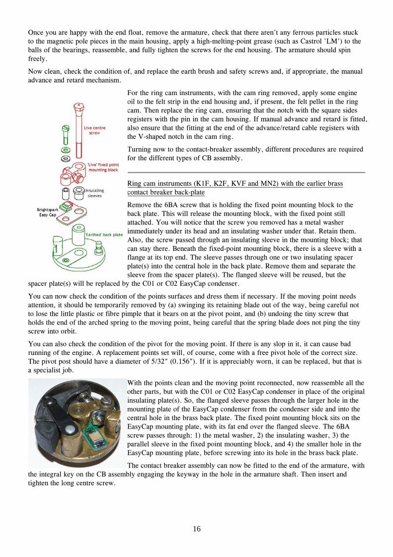
Ring cam instruments (K1F, K2F, KVF and MN2) with the earlier brass contact breaker back-plate
Remove the 6BA screw that is holding the fixed point mounting block to the back plate. This will release the mounting block, with the fixed point still attached. You will notice that the screw you removed has a metal washer immediately under its head and an insulating washer under that. Retain them. Also, the screw passed through an insulating sleeve in the mounting block; that can stay there. Beneath the fixed-point mounting block, there is a sleeve with a flange at its top end. The sleeve passes through one or two insulating spacer plate(s) into the central hole in the back plate. Remove them and separate the sleeve from the spacer plate(s). The flanged sleeve will be reused, but the
spacer plate(s) will be replaced by the C01 or C02 EasyCap condenser.
You can now check the condition of the points surfaces and dress them if necessary. If the moving point needs attention, it should be temporarily removed by (a) swinging its retaining blade out of the way, being careful not to lose the little plastic or fibre pimple that it bears on at the pivot point, and (b) undoing the tiny screw that holds the end of the arched spring to the moving point, being careful that the spring blade does not ping the tiny screw into orbit.
You can also check the condition of the pivot for the moving point. If there is any slop in it, it can cause bad running of the engine. A replacement points set will, of course, come with a free pivot hole of the correct size. The pivot post should have a diameter of 5/32" (0.156"). If it is appreciably worn, it can be replaced, but that is a specialist job.
With the points clean and the moving point reconnected, now reassemble all the other parts, but with the C01 or C02 EasyCap condenser in place of the original insulating plate(s). So, the flanged sleeve passes through the larger hole in the mounting plate of the EasyCap condenser from the condenser side and into the central hole in the brass back plate. The fixed point mounting block sits on the EasyCap mounting plate, with its fat end over the flanged sleeve. The 6BA screw passes through: 1) the metal washer, 2) the insulating washer, 3) the parallel sleeve in the fixed point mounting block, and 4) the smaller hole in the EasyCap mounting plate, before screwing into its hole in the brass back plate.
The contact breaker assembly can now be fitted to the end of the armature, with the integral key on the CB assembly engaging the keyway in the hole in the armature shaft. Then insert and tighten the long centre screw.

17
Ring cam instruments (K1F, K2F, KVF and MN2) with the later steel contact breaker back-plate
Remove the screw that is holding the spring anchor bracket and the fixed-point mounting plate to the back plate. You will notice that the screw has a metal washer immediately under its head and an insulating washer under that. Retain the metal washer. The insulating washer will, however, be replaced by the C04 EasyCap. You will see that there is a moulded nylon spacer between the spring anchor bracket and the fixed-point mounting plate. Note which way round it goes.
You can now check the condition of the points surfaces and dress them if necessary.
With the points clean and the moving point reconnected, now reassemble all the other parts, but with the C04 EasyCap condenser in place of the insulating washer with its capacitor elements uppermost as shown in the picture. So, the screw passes through: 1) the metal washer, 2) the EasyCap condenser, 3) the nylon insulator, and 4) the fixed point mounting plate, before screwing into its hole in the steel back plate. It is important that the end of the tiny screw that fixes the CB spring to its anchor bracket does not dig into the edge of the circuit board of the EasyCap.
The contact breaker assembly can now be fitted to the end of the armature, with the integral key on the CB assembly engaging the keyway in the hole in the armature shaft. Then insert and tighten the long centre screw.
Face cam instruments (MO1 and N1)
With the moving point removed, undo the screw that holds the moving-point mounting block to the back plate. It should have an insulating washer under its head, and there should be an insulating sleeve in its hole through the moving-point mounting block. There should also be one or more insulating plates between the moving-point mounting block and the back plate, and a flanged insulating sleeve that passes through those plate(s) into the hole in the back plate for the centre screw. The insulating plate(s) will be replaced by the C03
EasyCap.
You can now check the condition of the points surfaces and dress them if necessary.
With the points clean, reassemble all the other parts apart from the moving point, but with the C03 EasyCap condenser in place of the insulating plates between the moving-point mounting block and the back plate as shown in the picture. The plain insulating sleeve and the flanged insulating sleeve should both be reused, with the flanged sleeve passing through the larger hole in the EasyCap into the hole in the backplate for the centre screw. Check that the tappet is still in place, and apply a few drops of oil to the wick opposite the tappet on the underside of the back plate.
The contact breaker assembly can now be fitted to the end of the armature, with the notch in the end of the armature shaft properly engaging with the CB assembly. Insert and tighten the long centre screw. The refit the moving point. The points gap should now be adjusted to the value specified by the engine maker. If the setting is unknown, use between 0.012" and 0.015".
Finally, replace the end cover and the HT pick-up(s) having firstly checked that the brushes are in good condition and that there are no signs of tracking on the HT pickups.
Reinstalling the magneto on the machine Special tools required
• The same tools used to remove it
• Timing devices (consult your machine's service manual or appropriate web forum)

18
Procedure
Reinstalling the magneto involves the opposite steps to removal in reverse order. If you need a fresh gasket for the mounting flange and do not have one to hand, a pattern that may be of use to you is available for download at www.brightsparkmagnetos.com.
In addition, for chain driven magnetos, you will need to set the tension of the drive chain.
Lastly, you will need to set the ignition timing. Consult your machine's service manual or the appropriate web forum for your machine. If you do not have a timing disc and would like to make your own, you can download a pattern at www.brightsparkmagnetos.com.
Job finished!