britannia ª series b1 b2 b3 - zendesk · pdf fileuser manual britannia ª series b1...
TRANSCRIPT
USER MANUAL
Britannia™ Series
B1
B2
B3
REL Acoustics LimitedNorth Road, Bridgend Industrial EstateBridgend, CF31 3TPGreat Britain
Telephone: +44 (0) 1 656 768 777Fax: +44 (0) 1 656 766 093Web: www.rel.net
Downloaded from www.Manualslib.com manuals search engine

REL Acoustics Britannia Range User Manual
2
Downloaded from www.Manualslib.com manuals search engine
REL Acoustics Britannia Range User Manual
3
Contents
CONTENTS................................................................................................................................................... 3
IMPORTANT SAFEGUARDS ................................................................................................................... 4
WARNING..................................................................................................................................................... 4
WELCOME ................................................................................................................................................... 5
WORLD WIDE WARRANTY.................................................................................................................... 5
SERVICE AFTER WARRANTY.............................................................................................................. 5
DESIGN SAFETY......................................................................................................................................... 6
MAIN FEATURES OF THE REL BRITANNIA B1, B2 AND B3 SUB- BASS SYSTEMS............... 7
CONTROL PANEL...................................................................................................................................... 8
CONTROLS AND CONNECTIONS B1 ................................................................................................... 9
CONTROLS AND CONNECTIONS B2 ................................................................................................. 10
CONTROLS AND CONNECTIONS B3 ................................................................................................. 11
CONNECTING UP..................................................................................................................................... 13
TO CONNECT TO THE POWER AMPLIFIER USING THE UNBALANCED NEUTRIK HIGH LEVEL INPUT..... 13TO CONNECT TO MONO BLOCK POWER AMPLIFIERS USING THE HIGH LEVEL NEUTRIK
UNBALANCED INPUT ............................................................................................................................ 14TO CONNECT TO DIFFERENTIAL (BALANCED OUTPUT) POWER AMPLIFIERS USING THE BALANCEDHIGH LEVEL INPUT ..................................................................................................................................... 16TO CONNECT TO THE AMPLIFIER/PROCESSOR USING THE PHONO TO PHONO LOW LEVEL INTERCONNECT
................................................................................................................................................................... 17ALTERNATIVE METHOD FOR CONNECTING AT LOW LEVEL FROM PRE AMPLIFIER .................................. 18TO CONNECT TO A PRE AMPLIFIER WITH LOW LEVEL DIFFERENTIAL (BALANCED) OUTPUTS.................. 19
REL SET-UP MADE SIMPLE ................................................................................................................. 20
REL SET-UP MADE SIMPLER .............................................................................................................. 23
RUNNING IN .............................................................................................................................................. 24
OVERLOAD PROTECTION ................................................................................................................... 24
CARE AND POLISHING.......................................................................................................................... 24
TECHNICAL............................................................................................................................................... 25
POWER SAVING EFFICIENCY............................................................................................................. 26
TECHNICAL SPECIFICATIONS BRITANNIA RANGE B1, B2 AND B3 ...................................... 27
Downloaded from www.Manualslib.com manuals search engine
REL Acoustics Britannia Range User Manual
4
IMPORTANT SAFEGUARDS
1. Read all of these instructions.
2. Save these instructions for future use.
3. Unplug from the wall socket before cleaning. Do not use liquid cleaners or aerosolcleaners. Use a damp cloth for cleaning.
4. Do not use near water.
5. Do not place on a stand or table it may fall causing injury to a child or adult, and damageto the unit.
6. The unit should only be operated from the power source indicated on the panel of theamplifier.
7. Only use the power cord supplied.
8. Do not allow anything to rest on the power cord. Position the power cord such that itcannot be walked on.
9. For added protection during a lightening storm, or when not in use for long periods oftime, unplug it from the wall socket.
10. Never spill any kind of liquid on the unit.
11. Do not attempt to service the unit yourself, as removing the amplifier may expose you todangerous voltages. Refer all servicing to your dealer.
12. Unplug the unit from the wall socket and refer servicing to your dealer under the followingconditions:
a. When the power cord or plug is damaged.b. If liquid has been spilled onto the unit.c. If the unit does not operate properly by following the operating instructions.d. If the unit has been dropped and damaged.e. When the unit exhibits a drastic change in performance.
WARNING
These items are extremely heavy. To avoid risk of injury, take care when handling.
Downloaded from www.Manualslib.com manuals search engine
REL Acoustics Britannia Range User Manual
5
WELCOME
Thank you for buying a REL Britannia range Sub-Bass system. Our Britannia range is
carefully hand built using the finest materials available and is designed for maximum
performance. This manual contains important safety information as well as helpful advice and
should be carefully studied before connecting up.
WARRANTY
This product is warranted to be free of all defects in material and workmanship for three yearsfrom the date of original purchase by the original owner. A purchase receipt or other proof oforiginal purchase will be required before warranty service is rendered. This warranty is nottransferable and does not apply to any defects caused by negligence, accidents, misuse,modification, disassembly, or repair by other than the manufacturer, or by other than normaluse for which this product was intended. Within the period of this warranty, Sumiko will repairor replace at our service center located at 2431 Fifth St., Berkeley, CA 94710 any part provingdefective in material or workmanship. All expenses, except collateral expenses, related toreplacing or repairing a defective part under this warranty will be assumed by Sumiko, exceptfor the cost of transporting and insuring the product to our above-named service center. Thebuyer must notify Sumiko of any defect, malfunction, or nonconformity promptly upondiscovery. Within 30 business days after receiving the defective product from the buyer,Sumiko will repair or replace the defective part. We neither assume nor authorize anyrepresentative or other person to assume for us any other liability in connection with the salesor shipment of our products. We reserve the right to make changes or improvements in ourproducts without incurring any obligation to similarly alter products previously purchased. Thebuyer has the right to bring any action at law or equity to resolve disputes concerning or toenforce the provision of this warranty.
SERVICE AFTER WARRANTY
Please contact your dealer in the first instance before returning any product directly to us.
Should the unit need to be returned for any reason, all shipping costs will be payable by the
customer. Losses or damage caused during transit are the customer's risk.
Downloaded from www.Manualslib.com manuals search engine
REL Acoustics Britannia Range User Manual
6
DESIGN SAFETY
This apparatus is designed to Class II specification and is doubleinsulated, therefore it does not require to be grounded.
[Is below true, or should it be cut as indicated?]
This product is CE marked and has been tested to ensure it satisfies all relevant standards.
It satisfies all relevant standards for Conducted Emissions, Radiated Emissions,Susceptibility and Immunity.
It also complies with the requirements relating to class II construction detailed in clauses 9 &10 of BS EN 60065 1994
It also satisfies all relevant safety tests for consumer use provided it is used within theguidelines of this manual.
Downloaded from www.Manualslib.com manuals search engine
REL Acoustics Britannia Range User Manual
7
Main Features of the Rel Britannia B1, B2 and B3 SUB- BASS SYSTEMS
1. Separate volume controls for both high and low level inputs
2. Critically correct semitone resolution of the filter controls
3. Balanced and unbalanced inputs via high quality sockets
4. Mode switch to control phase and low level filter bypass
5. All components of matching superior quality to achieve both long-life and long-term
consistency of sound quality.
6. All cabinets made from 30 mm thick MDF.
7. Superior wood veneered finishes available for all models.
8. Set-Safe® circuitry ensuring ultimate protection if overloaded.
Downloaded from www.Manualslib.com manuals search engine
REL Acoustics Britannia Range User Manual
8
Control Panel
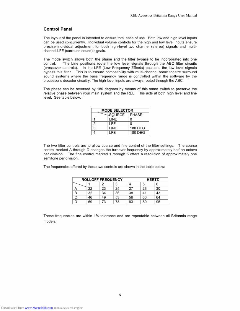
The layout of the panel is intended to ensure total ease of use. Both low and high level inputscan be used concurrently. Individual volume controls for the high and low level inputs ensureprecise individual adjustment for both high-level two channel (stereo) signals and multi-channel LFE (surround sound) signals.
The mode switch allows both the phase and the filter bypass to be incorporated into onecontrol. The Line positions route the low level signals through the ABC filter circuits(crossover controls). In the LFE (Low Frequency Effects) positions the low level signalsbypass this filter. This is to ensure compatibility with multi-channel home theatre surroundsound systems where the bass frequency range is controlled within the software by theprocessor’s decoder circuitry. The high level inputs are always routed through the ABC.
The phase can be reversed by 180 degrees by means of this same switch to preserve therelative phase between your main system and the REL. This acts at both high level and linelevel. See table below.
MODE SELECTORSOURCE PHASE
1 LINE 02 LFE 03 LINE 180 DEG4 LFE 180 DEG
The two filter controls are to allow coarse and fine control of the filter settings. The coarsecontrol marked A through D changes the turnover frequency by approximately half an octaveper division. The fine control marked 1 through 6 offers a resolution of approximately onesemitone per division.
The frequencies offered by these two controls are shown in the table below:
ROLLOFF FREQUENCY HERTZ1 2 3 4 5 6
A 22 23 25 27 28 30B 32 34 36 38 41 43C 46 49 53 56 60 64D 69 73 78 83 89 95
These frequencies are within 1% tolerance and are repeatable between all Britannia range
models.
Downloaded from www.Manualslib.com manuals search engine
REL Acoustics Britannia Range User Manual
9
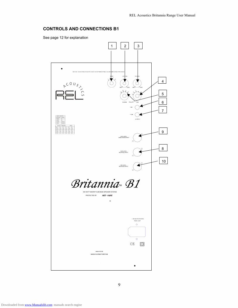
CONTROLS AND CONNECTIONS B1
See page 12 for explanation
1 2 3
4
5
6
7
9
8
10
HIGH LEVELUNBALANCED INPUT
CE
FUSE 6.3A/T
~ 100-120 VAC 50-60 HZ
300 WATT MOSFET SUB-BASS SPEAKER SYSTEM
PROTECTED BY
MADE IN GREAT BRITAIN
www.rel.net
R
HIGH LEVELBALANCED INPUT
Britannia B1TM
MAXMINMAXMIN
12 3
4
AB C
D
1
23
5
6
MODE LO LEVEL HI LEVEL
COARSE FINE
LO INPUT
0dB
+12dB
SOURCE
1
2
3
4
LINE
LFE
LINE
LFE
PHASE
0
0
180 deg
180 deg
MODE SELECTOR
ROLLOFF FREQUENCY
A
B
D
1 2 3 4 5 6
HERTZ
22 23 25 27 28 30
32 34 36 38 41 43
C 46 49 53 56 60 64
69 73 78 83 89 95
ROLLOFF
LINE LEVELBALANCED INPUT
Downloaded from www.Manualslib.com manuals search engine
REL Acoustics Britannia Range User Manual
10
CE
FUSE 6.3A/T
~ 100-120 VAC 50-60 HZ
200 WATT MOSFET SUB-BASS SPEAKER SYSTEM
PROTECTED BY
MADE IN GREAT BRITAIN
www.rel.net
R
Britannia B2TM
MAXMINMAXMIN
1
2 3
4
A
B C
D
1
2
3 4
5
6
MODE LO LEVEL HI LEVEL
COARSE FINE
LO INPUT
0dB
+12dB
SOURCE
1
2
3
4
LINE
LFE
LINE
LFE
PHASE
0
0
180 deg
180 deg
MODE SELECTOR
ROLLOFF
HIGH LEVELUNBALANCED INPUT
LINE LEVELBALANCED INPUT
HIGH LEVELBALANCED INPUT
ROLLOFF FREQUENCY
A
B
D
1 2 3 4 5 6
HERTZ
22 23 25 27 28 30
32 34 36 38 41 43
C 46 49 53 56 60 64
69 73 78 83 89 95
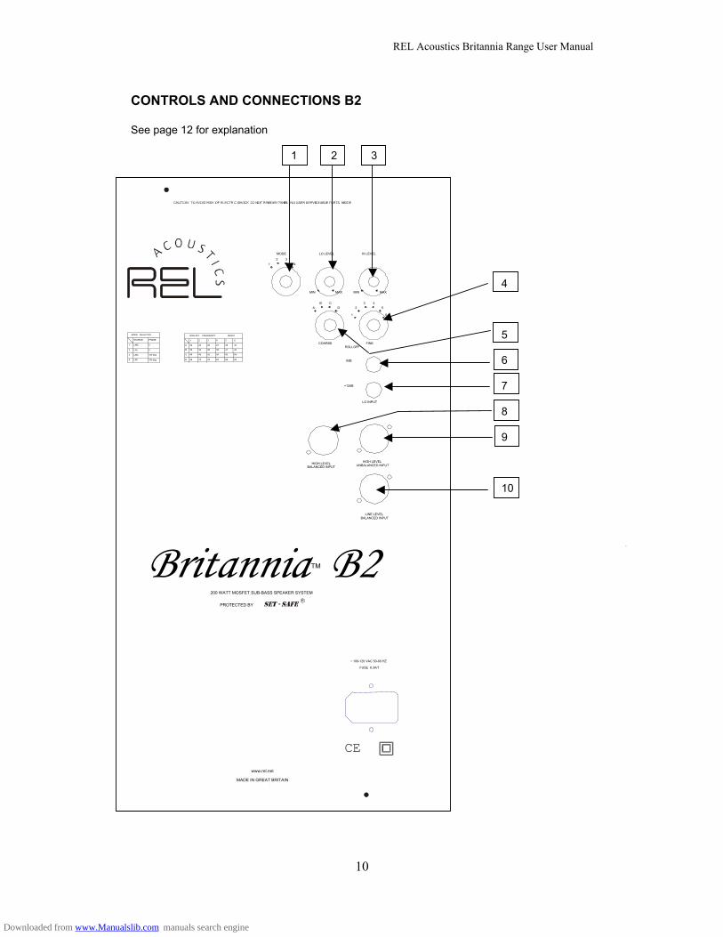
CONTROLS AND CONNECTIONS B2
See page 12 for explanation
1 2 3
4
5
6
7
8
9
10
Downloaded from www.Manualslib.com manuals search engine
REL Acoustics Britannia Range User Manual
11
HIGH LEVELUNBALANCED INPUT
CE
FUSE 3.15A/T
~ 100-120 VAC 50-60 HZ
150 WATT MOSFET SUB-BASS SPEAKER SYSTEM
PROTECTED BY
MADE IN GREAT BRITAIN
www.rel.net
R
HIGH LEVELBALANCED INPUT
Britannia B3TM
MAXMINMAXMIN
12 3
4
AB C
D
1
23 4
5
6
MODE LO LEVEL HI LEVEL
COARSE FINE
LO INPUT
0dB
+12dB
SOURCE
1
2
3
4
LINE
LFE
LINE
LFE
PHASE
0
0
180 deg
180 deg
MODE SELECTOR ROLLOFF FREQUENCY
A
B
C
D
1 2 3 4 5 6
HERTZ
22 23 25 27 28 30
32 34 36 38 41 43
46 49 53 56 60 64
69 73 78 83 89 95
ROLLOFF
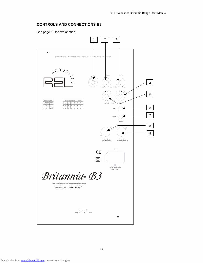
CONTROLS AND CONNECTIONS B3
See page 12 for explanation
1 2 3
4
5
6
7
8
9
Downloaded from www.Manualslib.com manuals search engine
REL Acoustics Britannia Range User Manual
12
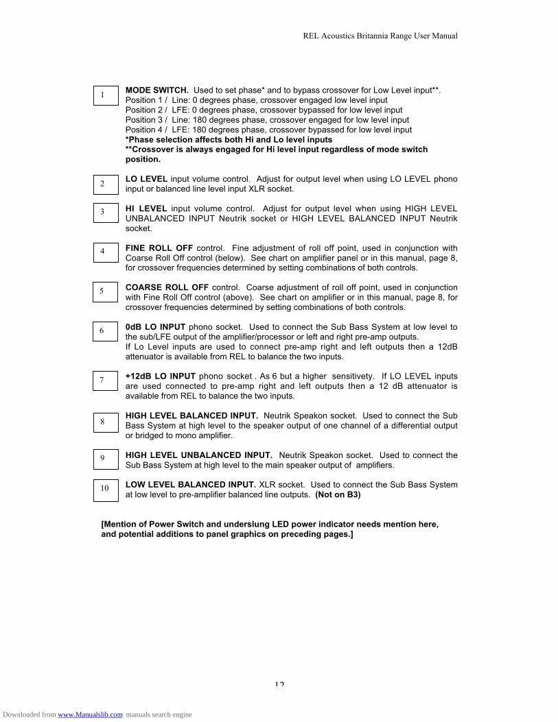
MODE SWITCH. Used to set phase* and to bypass crossover for Low Level input**.Position 1 / Line: 0 degrees phase, crossover engaged low level inputPosition 2 / LFE: 0 degrees phase, crossover bypassed for low level inputPosition 3 / Line: 180 degrees phase, crossover engaged for low level inputPosition 4 / LFE: 180 degrees phase, crossover bypassed for low level input*Phase selection affects both Hi and Lo level inputs**Crossover is always engaged for Hi level input regardless of mode switchposition.
LO LEVEL input volume control. Adjust for output level when using LO LEVEL phonoinput or balanced line level input XLR socket.
HI LEVEL input volume control. Adjust for output level when using HIGH LEVELUNBALANCED INPUT Neutrik socket or HIGH LEVEL BALANCED INPUT Neutriksocket.
FINE ROLL OFF control. Fine adjustment of roll off point, used in conjunction withCoarse Roll Off control (below). See chart on amplifier panel or in this manual, page 8,for crossover frequencies determined by setting combinations of both controls.
COARSE ROLL OFF control. Coarse adjustment of roll off point, used in conjunctionwith Fine Roll Off control (above). See chart on amplifier or in this manual, page 8, forcrossover frequencies determined by setting combinations of both controls.
0dB LO INPUT phono socket. Used to connect the Sub Bass System at low level tothe sub/LFE output of the amplifier/processor or left and right pre-amp outputs.If Lo Level inputs are used to connect pre-amp right and left outputs then a 12dBattenuator is available from REL to balance the two inputs.
+12dB LO INPUT phono socket . As 6 but a higher sensitivety. If LO LEVEL inputsare used connected to pre-amp right and left outputs then a 12 dB attenuator isavailable from REL to balance the two inputs.
HIGH LEVEL BALANCED INPUT. Neutrik Speakon socket. Used to connect the SubBass System at high level to the speaker output of one channel of a differential outputor bridged to mono amplifier.
HIGH LEVEL UNBALANCED INPUT. Neutrik Speakon socket. Used to connect theSub Bass System at high level to the main speaker output of amplifiers.
LOW LEVEL BALANCED INPUT. XLR socket. Used to connect the Sub Bass Systemat low level to pre-amplifier balanced line outputs. (Not on B3)
[Mention of Power Switch and underslung LED power indicator needs mention here,and potential additions to panel graphics on preceding pages.]
1
2
3
4
6
7
8
9
10
5
Downloaded from www.Manualslib.com manuals search engine
REL Acoustics Britannia Range User Manual
13
CONNECTING UP
Always switch off your system before disconnecting any wires
To increase the versatility of connecting up, the Britannia range has various separate inputsdepending on the model, see pages 9,10 and 11.
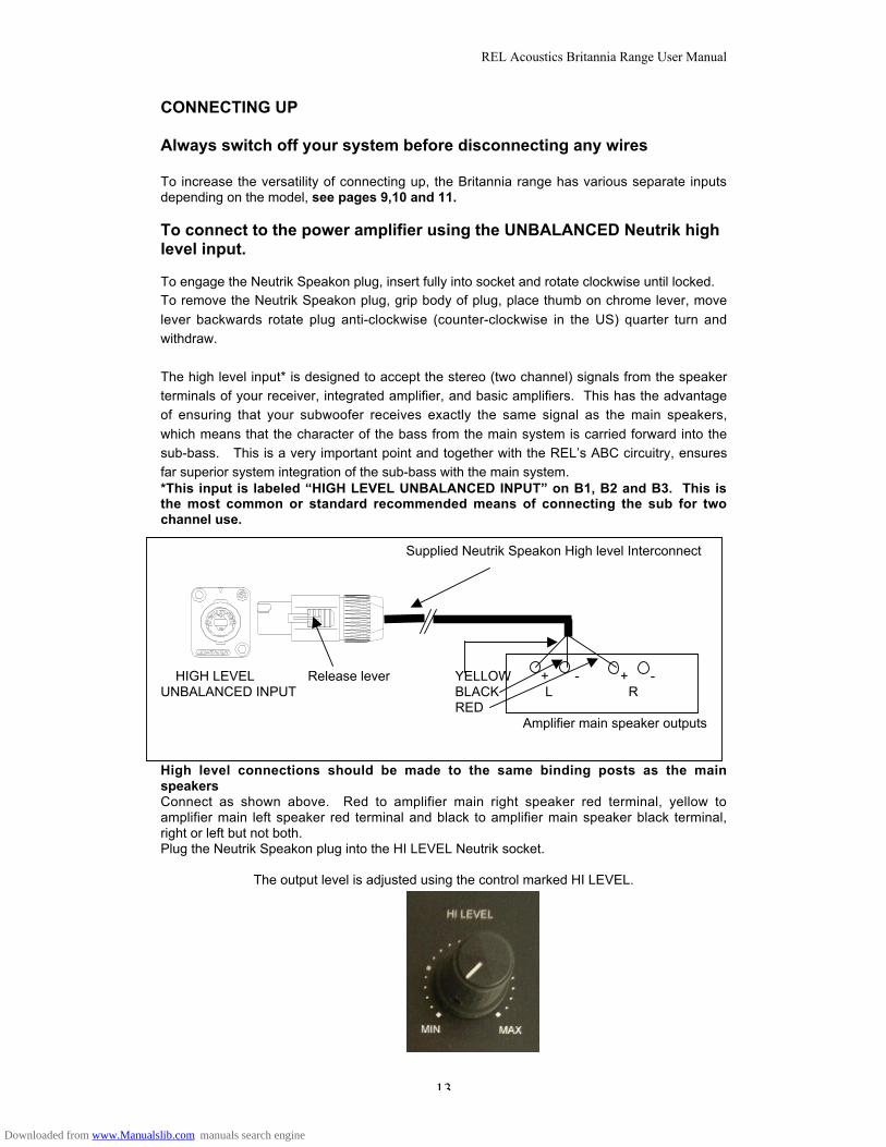
To connect to the power amplifier using the UNBALANCED Neutrik highlevel input.
To engage the Neutrik Speakon plug, insert fully into socket and rotate clockwise until locked.To remove the Neutrik Speakon plug, grip body of plug, place thumb on chrome lever, move
lever backwards rotate plug anti-clockwise (counter-clockwise in the US) quarter turn and
withdraw.
The high level input* is designed to accept the stereo (two channel) signals from the speaker
terminals of your receiver, integrated amplifier, and basic amplifiers. This has the advantage
of ensuring that your subwoofer receives exactly the same signal as the main speakers,
which means that the character of the bass from the main system is carried forward into the
sub-bass. This is a very important point and together with the REL’s ABC circuitry, ensures
far superior system integration of the sub-bass with the main system.*This input is labeled “HIGH LEVEL UNBALANCED INPUT” on B1, B2 and B3. This isthe most common or standard recommended means of connecting the sub for twochannel use.
Supplied Neutrik Speakon High level Interconnect
HIGH LEVEL Release lever YELLOW + - + -UNBALANCED INPUT BLACK L R
RED Amplifier main speaker outputs
High level connections should be made to the same binding posts as the mainspeakersConnect as shown above. Red to amplifier main right speaker red terminal, yellow toamplifier main left speaker red terminal and black to amplifier main speaker black terminal,right or left but not both.Plug the Neutrik Speakon plug into the HI LEVEL Neutrik socket.
The output level is adjusted using the control marked HI LEVEL.
Downloaded from www.Manualslib.com manuals search engine
REL Acoustics Britannia Range User Manual
14
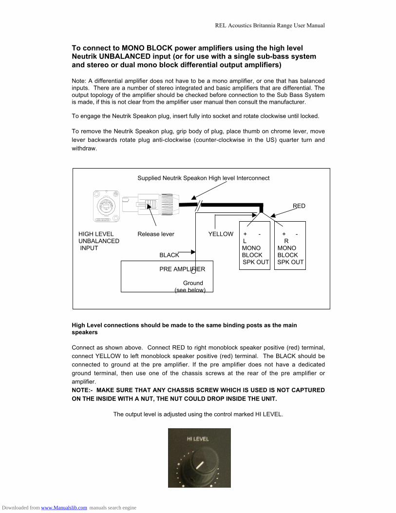
To connect to MONO BLOCK power amplifiers using the high levelNeutrik UNBALANCED input (or for use with a single sub-bass systemand stereo or dual mono block differential output amplifiers)
Note: A differential amplifier does not have to be a mono amplifier, or one that has balancedinputs. There are a number of stereo integrated and basic amplifiers that are differential. Theoutput topology of the amplifier should be checked before connection to the Sub Bass Systemis made, if this is not clear from the amplifier user manual then consult the manufacturer.
To engage the Neutrik Speakon plug, insert fully into socket and rotate clockwise until locked.
To remove the Neutrik Speakon plug, grip body of plug, place thumb on chrome lever, move
lever backwards rotate plug anti-clockwise (counter-clockwise in the US) quarter turn and
withdraw.
Supplied Neutrik Speakon High level Interconnect
RED
HIGH LEVEL Release lever YELLOW + - + - UNBALANCED L R INPUT MONO MONO
BLACK BLOCK BLOCKSPK OUT SPK OUT
PRE AMPLIFIER
Ground (see below)
High Level connections should be made to the same binding posts as the mainspeakers
Connect as shown above. Connect RED to right monoblock speaker positive (red) terminal,
connect YELLOW to left monoblock speaker positive (red) terminal. The BLACK should be
connected to ground at the pre amplifier. If the pre amplifier does not have a dedicated
ground terminal, then use one of the chassis screws at the rear of the pre amplifier or
amplifier.
NOTE:- MAKE SURE THAT ANY CHASSIS SCREW WHICH IS USED IS NOT CAPTURED
ON THE INSIDE WITH A NUT, THE NUT COULD DROP INSIDE THE UNIT.
The output level is adjusted using the control marked HI LEVEL.
Downloaded from www.Manualslib.com manuals search engine

REL Acoustics Britannia Range User Manual
15
Downloaded from www.Manualslib.com manuals search engine
REL Acoustics Britannia Range User Manual
16
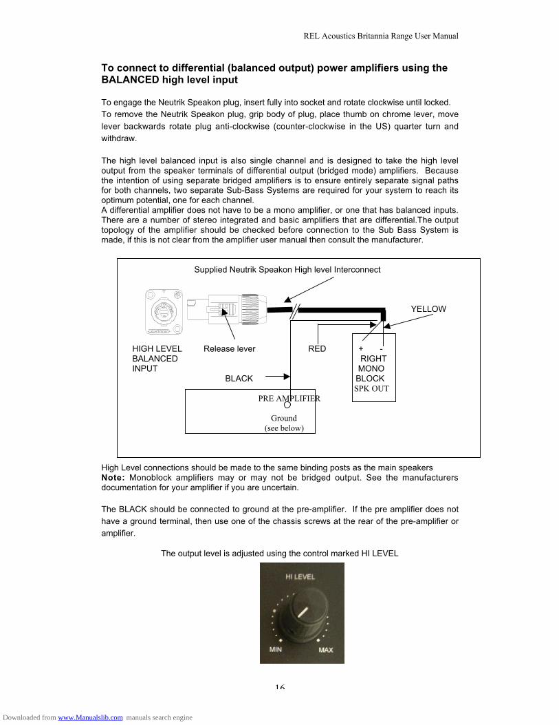
To connect to differential (balanced output) power amplifiers using theBALANCED high level input
To engage the Neutrik Speakon plug, insert fully into socket and rotate clockwise until locked.To remove the Neutrik Speakon plug, grip body of plug, place thumb on chrome lever, move
lever backwards rotate plug anti-clockwise (counter-clockwise in the US) quarter turn and
withdraw.
The high level balanced input is also single channel and is designed to take the high leveloutput from the speaker terminals of differential output (bridged mode) amplifiers. Becausethe intention of using separate bridged amplifiers is to ensure entirely separate signal pathsfor both channels, two separate Sub-Bass Systems are required for your system to reach itsoptimum potential, one for each channel.A differential amplifier does not have to be a mono amplifier, or one that has balanced inputs.There are a number of stereo integrated and basic amplifiers that are differential.The outputtopology of the amplifier should be checked before connection to the Sub Bass System ismade, if this is not clear from the amplifier user manual then consult the manufacturer.
Supplied Neutrik Speakon High level Interconnect
YELLOW
HIGH LEVEL Release lever RED + - BALANCED RIGHTINPUT MONO
BLACK BLOCK SPK OUT
PRE AMPLIFIER
Ground (see below)
High Level connections should be made to the same binding posts as the main speakersNote: Monoblock amplifiers may or may not be bridged output. See the manufacturersdocumentation for your amplifier if you are uncertain.
The BLACK should be connected to ground at the pre-amplifier. If the pre amplifier does not
have a ground terminal, then use one of the chassis screws at the rear of the pre-amplifier or
amplifier.
The output level is adjusted using the control marked HI LEVEL
Downloaded from www.Manualslib.com manuals search engine

REL Acoustics Britannia Range User Manual
17
To connect to the amplifier/processor using the phono to phono lowlevel interconnect
Two low level inputs are provided, 0dB and +12dB,Connect as shown above using a phono to phono interconnect (not supplied). Plug one endinto the sub/LFE output on the amplifier/processor and the other end into the 0dB input on thesub woofer.If when using the 0dB input the output of the sub woofer is too low then use the +12dB input.
The output level is adjusted using the control marked LO LEVEL
If the low level connection is to be made to left and right pre-amp outputs then a 12dBattenuator is available to balance the 0dB and +12dB phono inputs. See below.
Phono to Phono Interconnect.(Not supplied) To sub/LFE output of
Amplifier/Processor
Sub Low Level Input
.
Sub Low Level 12dB Phono to phono Input Attenuator interconnect (Not supplied)
Downloaded from www.Manualslib.com manuals search engine
REL Acoustics Britannia Range User Manual
18
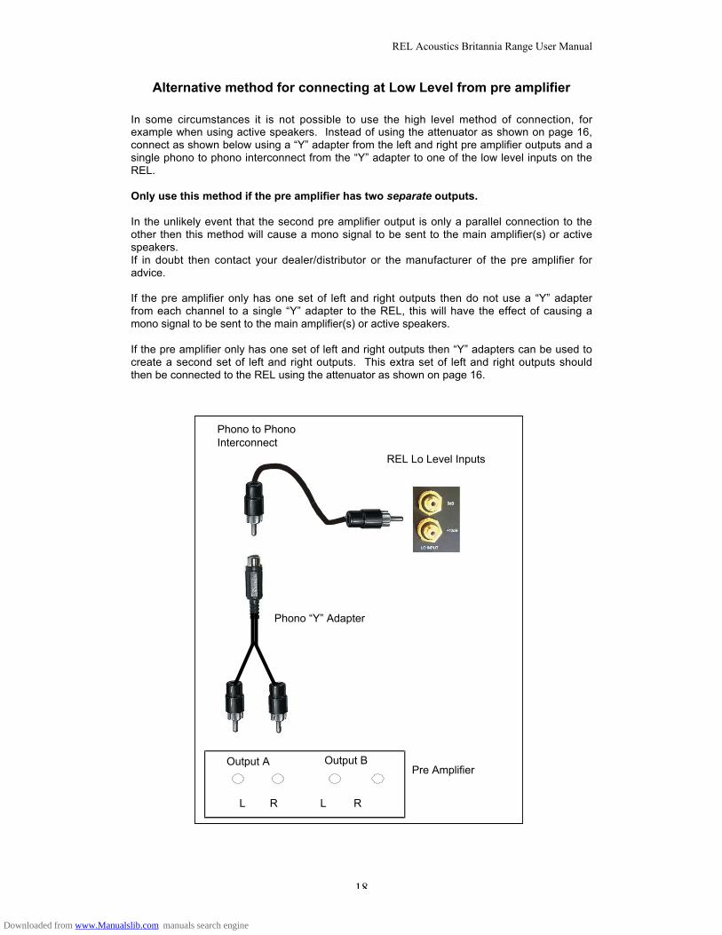
Alternative method for connecting at Low Level from pre amplifier
In some circumstances it is not possible to use the high level method of connection, forexample when using active speakers. Instead of using the attenuator as shown on page 16,connect as shown below using a “Y” adapter from the left and right pre amplifier outputs and asingle phono to phono interconnect from the “Y” adapter to one of the low level inputs on theREL.
Only use this method if the pre amplifier has two separate outputs.
In the unlikely event that the second pre amplifier output is only a parallel connection to theother then this method will cause a mono signal to be sent to the main amplifier(s) or activespeakers.If in doubt then contact your dealer/distributor or the manufacturer of the pre amplifier foradvice.
If the pre amplifier only has one set of left and right outputs then do not use a “Y” adapterfrom each channel to a single “Y” adapter to the REL, this will have the effect of causing amono signal to be sent to the main amplifier(s) or active speakers.
If the pre amplifier only has one set of left and right outputs then “Y” adapters can be used tocreate a second set of left and right outputs. This extra set of left and right outputs shouldthen be connected to the REL using the attenuator as shown on page 16.
Pre Amplifier
L R L R
Output A Output B
REL Lo Level Inputs
Phono “Y” Adapter
Phono to PhonoInterconnect
Downloaded from www.Manualslib.com manuals search engine
REL Acoustics Britannia Range User Manual
19
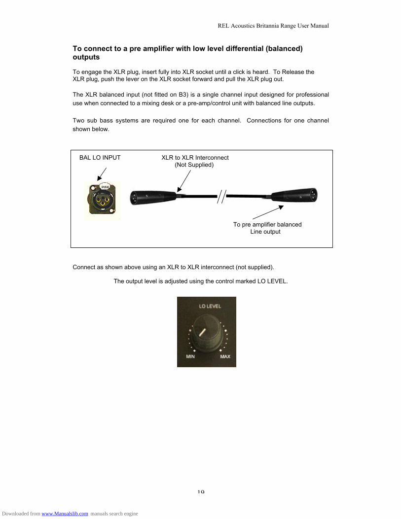
To connect to a pre amplifier with low level differential (balanced)outputs
To engage the XLR plug, insert fully into XLR socket until a click is heard. To Release theXLR plug, push the lever on the XLR socket forward and pull the XLR plug out.
The XLR balanced input (not fitted on B3) is a single channel input designed for professional
use when connected to a mixing desk or a pre-amp/control unit with balanced line outputs.
Two sub bass systems are required one for each channel. Connections for one channel
shown below.
BAL LO INPUT XLR to XLR Interconnect (Not Supplied)
To pre amplifier balanced Line output
Connect as shown above using an XLR to XLR interconnect (not supplied).
The output level is adjusted using the control marked LO LEVEL.
Downloaded from www.Manualslib.com manuals search engine
REL Acoustics Britannia Range User Manual
20
REL Set-Up Made Simple
RELs are not traditional subwoofers, but true sub-bass systems. A REL is designed toaugment the performance of “full range” speaker systems, to provide linear response down tobelow 12 Hz. Therefore, for the moment, set aside everything you’ve been taught aboutsubwoofers and how they are integrated into a stereo or theatre system. REL’s set-up andpositioning differs from other subwoofers. A REL will take advantage of physics and roomacoustics to provide deep pressurisation as no other sub-woofer can. It’s important that youbring to the set-up process a willingness to do things a little differently in order to obtain thesesuperior results. The end result of your labours will be an utterly seamless integration of truedeep bass to a sound system, regardless of the main speaker’s low bass capability.
Two Things Before You Begin
A. It is helpful to know that you will almost always connect the REL to the input on therear panel labelled “HIGH LEVEL.” This connection is made using the supplied 34’10” (10 meters) cable, the bare leads of which connect to the speaker outputterminals of the power amplifier. The easy and foolproof connection at the REL isdone with a Neutrik Speakon connector. The purpose of connecting to the speakeroutput terminals is one of the unique secrets of REL’s success. By connecting to thehigh level input on the REL from the amplifier, you build forward the sonic signature ofyour main system, including the tonal balance and timing cues of the entireelectronics chain. In this way, the REL is fed the exact signal that is fed to the mainspeakers.
B. When possible, the REL should be placed in one of the corners behind the speakers.Remember, we are dealing with true LOW bass pressurisation with RELs, not themid-bass that most competitors settle for. Low bass pressurisation below 40Hz isbest derived from corner placement, where the most linear and efficient low bass canbe produced.
Basic set-up should take no more than ten to fifteen minutes to accomplish once connected.
ConnectingHigh-level connection, using the enclosed cable with the Neutrik Speakon connector,is always the first choice. By connecting to the amplifier’s speaker outputs the sonicsignature of the entire amplification chain is folded into the signal for the sub, therebykeeping timing and timbre cues consistent. In other words, the signal sent to the RELis exactly the same signal sent to the speakers, allowing for seamless integration. Thisconnection can be made without affecting the performance of the amplifier becausethe sub’s amplifier input impedance is 100,000 ohms. This scheme also avoids addingany detrimental effects by not interposing any additional electronics into theamplification chain.
• The standard high level hook up procedure is: attach the red wire to the amplifier’sright positive speaker output terminal; attach the yellow wire to the amplifier’s leftpositive speaker output terminal; attach the black wire to which ever of the amplifier’sground output terminals is convenient; plug the Speakon connector into the sub’shigh level input.
• For differential amplifiers using one sub, simply use the standard connecting schemewith the exception of connecting ground to chassis ground, not to speaker outputground, and then connecting into the HIGH LEVEL UNBALANCED INPUT.
• For differential amplifiers using two subs, one for each channel: connect red topositive; yellow to negative; and black to chassis ground; plug the Speakon into theHIGH LEVEL BALANCED INPUT.
Low-level connection, RCA inputs (or XLR on some models), is always an option, shouldhigh-level connection not be possible, or in a theatre system where both high-level and low-level connection should be used. When connecting to the low level inputs, connect a singleRCA cable to the 0dB RCA jack. Additional gain can be achieved by connecting to the +12dBinput.
Downloaded from www.Manualslib.com manuals search engine
REL Acoustics Britannia Range User Manual
21
PositioningThe optimal position for a REL is in one of the corners behind the main speakers, with thedriver pointed directly out of the corner towards the centre of the room. This position provides9 dB of mechanical amplification and allows for the most linear true low bass wave launch,owing to the ability to tune the sub to the axial node of the room, or longest throw distance.
The ProcessTo begin the set-up process, choose a piece of music that has a repetitive bass line that isvery low in frequency. We recommend cut 4 from the soundtrack to Sneakers (Columbia CK53146). This has a repetitive bass drum throughout that gives you plenty of time to move thewoofer around, but more importantly, the recording venue was quite large for this recording,and therefore it has a very deep and large-scale bass signature. This type of cut is perfect forthe set-up process, and should be played at the highest reasonable level expected for systemplay back.
Working with a partner, one in the listening position and one at the woofer manipulating thecontrols is the most effective and efficient ways to set up the woofer. If working alone, theinitial steps in the set-up can very effectively be carried out from the location of the woofer.Trying to ignore all other music in the cut, listen for the bass drum and its effect on thelistening room.
1. Phase Orientation: Once in the corner we need to adjust for phase. This may be thesingle most critical step, and because it really is quite simple, it is often over thought,especially by the most experienced audiophiles. Keep in mind; the right phase iswhichever position is the loudest or fullest. While playing music with true low bass,adjust the crossover to a point where the sub and the speaker are sure to sharefrequencies (B, 3 for big speakers or C, 4 for smaller speakers). At this point turn thegain so that both sub and speaker are roughly equal and then switch, using the“mode selector” switch, from “0” (position 1) to “180” (position 3) phase positions.Again, whichever position is loudest or fullest is the correct position, and, as often asnot, may be 180-degree phase. That is, this position is working in harmony with yourmain speakers, reinforcing bass, and not cancelling it.
2. Placement: The next step is to determine precisely how far out from the corner thesub should be placed to achieve the most efficient output, as well as the lowestfrequency extension. With the sub fully into the corner, continuing to play the music,slowly pull the sub from the corner on the diagonal, equidistant from both side andrear wall. At a certain point (sometimes a matter of only a few inches, in rare cases afoot or more) the sub will audibly go lower, play louder, and, if it truly locks on to theroom and is fully pressurising it, the air around the sub will seem to be energised,stop right there! This is the correct position for the sub.
3. Orientation: Once the position from the corner has been established, the orientationof the woofer must be determined by rotating the REL from an imagined centre pointat the rear of the sub. As the sub is moved from one side to the other listen for thegreatest level of output and bass linearity. In effect, the sub should left in the positionwhere it is playing the loudest and lowest.
Crossover and Gain Settings: To determine the crossover point, bring the gain down, put thecrossover to A-1, bring the gain back up to the point where you have achieved a subtlebalance (In some situations where there may not be sufficient output due to room andsubwoofer interactions B-1 should be the position to use in setting initial gain). Working onlywith the coarse control (A-D), bring the crossover point up until it is obviously too high, at thispoint bring it down to the next lowest setting. Now, working with the fine control (1-6), bring upthe crossover point until it sounds too high, at which point bring it back down to the nextlowest setting. For all intents and purposes, this is the correct crossover point. Once thisstage has been reached, subtle changes to gain and crossover can be accomplished toprovide the last bit of complete and seamless integration. In addition, a repetition of step 3above, orientation, may provide further, albeit subtle, improvement of the sub-bass system’sintegration with the main speakers. With that, set-up is complete.
Downloaded from www.Manualslib.com manuals search engine
REL Acoustics Britannia Range User Manual
22
Hint: There is a tendency among audiophiles to set the crossover point too high and the gaintoo low when first learning how to integrate a REL with the system, the fear being one ofoverwhelming the main speakers with bass. But in doing so, the resulting set-up will belacking in bass depth and dynamics. The proper crossover point and gain setting will increaseoverall dynamics, allow for extended bass frequencies, and improve soundstage properties.Note: gain must be adjusted in conjunction with crossover changes. In general, whenselecting a lower crossover point, more gain may need to be applied.
Theatre and Film Applications: For Dolby Digital AC-3 or other 5.1 theatre systems, oncethe standard set-up for two-channel outlined above is complete, the LFE output from theprocessor or receiver should be connected to the low-level input and appropriate gainadjustments made. It may be necessary to take the crossover out of the low-level input usingthe “mode” switch if extra upper bass output is called for. Keep phase consistent with whatwas selected during high-level set-up by simply choosing the corresponding setting (1 = 2, 3 =4). For this configuration, you must set the processor to the “large” or “full range” setting forthe left and right speakers in order for the REL to receive the bass signal via the high-levelcable. In this configuration, the REL provides support for both the left and right speakers fortwo-channel listening, and support for the LFE when movies are playing. Most processors willallow you to defeat the subwoofer output when listening in the two-channel mode. The effectof this set-up is one of greatly increased dynamics in the mid-bass range; no bass bloat; anda greater degree of space and timing from the Foley effects. For an even greater sense ofspace and impact, a second woofer connected in parallel to the centre channel will prove tobe a dramatic improvement as well. And if that is not enough fun, a rear sub, both to supportthe rear channel speakers as well as to evenly distribute LFE through the room, trulycompletes the full-range sonic picture for state-of-the-art film reproduction. A comprehensiveset-up paper for home theatre will be coming very soon.
Other Tips: Generally speaking, do not use the supplied spikes. RELs work on the principle ofthe driver in a high-pressure zone relative to the floor. Spiking the REL will decouple thewoofer from the floor, which will lean out the bass response. If the floor is an older, very“springy” floor, spikes can be useful in reducing the influence of the REL on the floor. Butbetter yet, a heavy stone slab placed under the REL will work better. Even if you intend to usethe spikes, do NOT insert them until completion of the set-up process. After which, subtleadjustments to crossover and gain may be necessary
Downloaded from www.Manualslib.com manuals search engine

REL Acoustics Britannia Range User Manual
23
REL Set-Up Made Simpler
ConnectingHigh-level connection, using the enclosed cable, is always the first choice. Thestandard high level hook up procedure is: attach the red wire to the amplifier’s rightpositive speaker output terminal; attach the yellow wire to the amplifier’s left positivespeaker output terminal; attach the black wire to which ever of the amplifier’s groundoutput terminals is convenient; plug the connector into the “HIGH LEVELUNBALANCED INPUT” input. For connection to a differential amplifier consult yourdealer.
PositioningPrimary Placement, for a REL is in one of the corners behind the main speakers.Phase Selection is the next step. Keep in mind; the correct phase is whichever position is theloudest or fullest. While playing music with true low bass, adjust the crossover to a pointwhere the sub and the speaker are sure to share frequencies (B, 3 for big speakers; C, 4 forsmaller speakers). At this point adjust the gain so that both sub and speaker are roughlyequal in output and then switch, using the “mode selector” switch, from “0” (position 1) to“180” (position 3) phase positions. Again, whichever position is loudest or fullest is the correctposition, and, as often as not, may be 180-degree phase (see enclosed “Control Panel”section from the owner’s manual).Position. The next step is to determine precisely how far out from the corner the sub shouldbe to achieve the most efficient output, as well as the lowest frequency extension. With thesub fully into the corner, continuing to play the music, slowly pull the sub from the corner onthe diagonal, equidistant from both side and rear wall. At a certain point (sometimes a matterof only a few inches, in rare cases a foot or more) the sub will audibly go lower, play louder,and, if it truly locks on to the room and is fully pressurising it, the air around the sub will seemto be energised. Stop right there! This is the correct position for the sub.Orientation. Once the position from the corner has been established, the orientation of thewoofer must be determined by rotating the REL from an imagined centre point at the rear ofthe sub. As the sub is moved from one side to the other listen for the greatest level of outputand bass linearity. In effect, the sub should left in the position where it is playing the loudestand lowest.
AdjustingCrossover Selection. To determine the crossover point, bring the gain down, put thecrossover to A-1 (or B-2 should output not be sufficient), and then bring the gain back up tothe point where you have achieved a subtle balance. Working only with the coarse control (A-D), bring the crossover point up until it is obviously too high, at this point bring it down to thenext lowest setting. Now, working with the fine control (1-6), bring up the crossover point untilit sounds too high, at which point bring it back down to the next lowest setting. For all intentsand purposes, this is the correct crossover point. Once this stage has been reached, subtlechanges to gain and crossover can be accomplished to provide the last bit of complete andseamless integration. In addition, subtle adjustments of the orientation of the sub may providefurther improvement of the sub-bass system’s integration with the main speakers.
Including TheatreMulti-channel systems LFE output should be connected to the low-level input and appropriategain adjustments made at this point. It may be necessary to take the crossover out of the low-level input using the “mode” switch if extra upper bass output is called for. Keep phaseconsistent with what was selected during high-level set-up by simply choosing thecorresponding setting (1 = 2, 3 = 4). When connecting to the low level inputs, connect a singleRCA cable to the 0dB RCA jack. Should additional gain be required, connect to the +12 dBinput.
Downloaded from www.Manualslib.com manuals search engine
REL Acoustics Britannia Range User Manual
24
RUNNING IN
Care taken over running in will be rewarded by many years of pleasurable use. Both theelectronics and the drive unit will benefit from an initial period of carefully controlled use.Possible damage may be sustained by running in the unit at too high a volume setting over anextended period. On the other hand, by taking a little care over this initial period, about 24hours of actual use, a longer life with a higher potential eventual performance is assured.
OVERLOAD PROTECTION
REL Sub-Bass Systems are designed as true sub-bass speakers. They are designed toreproduce those exceptionally deep notes that are felt rather than heard. This they willattempt to do at whatever volume level you set. If set too high no damage should resultbecause the built-in electronics will limit the cone movement. This electronic control is calledSet-Safe®. It constantly and instantaneously monitors the output from the power amplifierand is totally transparent in operation until required. This means it has absolutely no effect onthe sound quality of any REL Sub-Bass System until an overload is detected. Ordinarily anoverload would cause the power amplifier to go into clipping with resultant loss of control overthe drive unit. Apart from being sonically offensive, this can cause drive unit damage. Set-Safe® detects the point of incipient clipping and reduces the signal level to ensure actualclipping does not occur.
Even without Set-Safe® overload would be a difficult thing to achieve because REL Sub-bassSystems have particularly high current amplifiers and very powerful drive units specificallydesigned for high sound pressure levels.
From our tests, we believe it would be very difficult to deliberately damage a REL Sub-bassSystem. Nevertheless, anything can be damaged if sufficient effort is made. Althougheverything possible has been done to minimise damage from moderate attempts atoverloading, there can be no defence against those individuals who deliberately andperversely abuse the device. Such damage is NOT covered by Warranty. Please remember,a REL Sub-Bass System is there to supplement your main system, not to overwhelm it!
CARE AND POLISHING
Brittex (sprayed) finishes:These are best maintained by careful dusting with a lint free cloth. Alternatively, a softbristled brush may be used to sweep off any dust failing on the surface. If objects are to beplaced upon the top, it is advisable to use a small mat to protect the surface and to avoid therisk of rattles.
Wood veneer finishes:Dusting as above, plus the occasional polishing with a good quality furniture polish for thewood veneers. Treat the finish as you would any other piece of quality furniture in your home.
Downloaded from www.Manualslib.com manuals search engine
REL Acoustics Britannia Range User Manual
25
TECHNICAL
The Britannia range utilizes an unique (Patent applied for) loading system called AcousticResistive Matrix (ARM) loading. This unique to REL system offers significant advantagesover conventional reflex loading. Firstly, it significantly lowers the system resonantfrequency, this on its own is a very worthwhile advantage over simple reflex loading, but italso offers the very important benefit of much reduced port noise (chuffing). Its action is across between ordinary reflex loading and a transmission line. Because it has similaritiesto a transmission line, it means it also has less stored energy compared to a reflex, thistranslates into a faster sound. Rhythmic timing is improved, yet it also offers far higheroutput sound pressure levels for its driver size compared to a closed box. By designing theport to fire down onto the floor, it means the Britannia series have all the benefits of adownward firing sub, but also all the benefits of forward firing for impact and excellentdynamics for home movies. Remember the very lowest frequencies that are felt, ratherthan heard, emanate from the port, it is somewhat similar to having two drive units, eachoptimised for it’s particular purpose.
The particular adaptation of ARM loading used in the new Britannia series is a thirdgeneration on from our previous methods. A lot of thought and experimenting has goneinto these models to ensure they represent the highest possible performance for their size.
Each cabinet is manufactured from 30 mm thick MDF (Medium Density Fibreboard). Thisis the material of choice where the very highest quality is demanded. There can be nosubstitute for weight and density as far as low frequencies are concerned.
Each model in the Britannia range uses incrementally more powerful drive units, amplifiersand larger cabinets compared to the base model. The drive unit fitted to B3 is a bespokedriver with an exceptionally heavy and powerful motor assembly. This is very important tomaximise dynamics and control. The driver fitted to the B2 mode is an upgraded B3 driverwith a heavier cast chassis, this driver handles greater power both through greater linearextension and the ability to dissipate more heat, and this translates into greater bass depthand volume. To help control this power and to further minimise port noise, both the B2 andthe B1 models incorporate Balanced ARM loading. This is a refinement of the ARMloading that is used in the B3, it offers even greater bass depth and increased powerhandling without excessive port noise. The B1 model represents state of the art design.Because it has a 12 inch drive unit and an even more powerful amplifier together withBalanced ARM loading (as in B2) it can approach sound pressure levels that can be toohigh for comfort. The port noise of all models is very low and is totally innocuous inpractice.
All REL amplifiers are fully DC coupled to avoid phase shifts and compromises in their lowend performance. The line level and filter stages are fully regulated to ensure totalisolation from the power amp stages. The filter stages are unique designs using the highestquality components. The capacitors are high quality nitrogen filled polystyrene types of 1%very close tolerance and an indefinite life. The use of very close tolerance componentsalso ensures consistency of performance throughout the production life of each model.
The filter board is identical for all three models and is designed so that each fineadjustment equates to a semitone, offering musically correct increments of the filter.
There is further filtering of the higher frequencies to ensure optimum performance at allsettings of the ABC. The built-in power amplifier is built onto a separate circuit board anduses ultra rugged audio grade MOSFET output devices. The power supply is the enginehouse of the amplifier, the smoothing capacitors are long life with very low equivalentseries resistance (ESR), and the bridge rectifier is very conservatively rated at 35Amps.Most of our competitors boast about using 6 Amp or perhaps 10 Amp rectifiers. We feelthis is short-changing the customer. It must mean a higher impedance path between thesource of power (the AC mains) and the amplifier supply rails. The transformers are ultraquiet audio quality toroid types with very low losses, these are especially manufactured toour strict specifications. Great care has been taken to deliberately over engineer all RELproducts to ensure ruggedness in service. This ensures an exceptionally robust, longlasting device. For all practical purposes it will probably outlast its owner!
Downloaded from www.Manualslib.com manuals search engine

REL Acoustics Britannia Range User Manual
26
POWER SAVING EFFICIENCY
All REL Sub-Bass Systems are designed for maximum power efficiency, both when passinga signal through to its resultant output sound into the room and also when silent.
REL circuitry is designed for “power starvation” operation under no signal conditions. Thismeans that immediately when there is a gap in the signal the sub is instantly at maximumpower saving efficiency, yet remains at maximum readiness to respond immediately to asudden transient signal, such as an explosion in a movie, even after a long quiet period andat whatever level.
This compares to some “auto power on/off systems” which remain powered up for a setperiod of no-signal condition (up to 10-15 minutes) and which need to power-up on receiptof a sudden transient thus failing to catch the start of that transient. There is also thepossibility of the sub remaining inoperative during listening sessions where the overallvolume is low.
It is not necessary to switch off between listening sessions - it will not significantly shortenits life by leaving it switched on. On the other hand, it will not harm sound quality if it isalways switched off. The power consumption in the quiescent (no signal) state is negligible.REL’s power starvation technology uses less than 4w when idle (less than 1/25th the powerof a standard light bulb).
It is perfectly safe under all normal domestic circumstances as it is fully protected byinternal fuses and an external mains fuse in the sliding drawer of the mains input socket,with a spare inside this drawer.
Downloaded from www.Manualslib.com manuals search engine
REL Acoustics Britannia Range User Manual
27
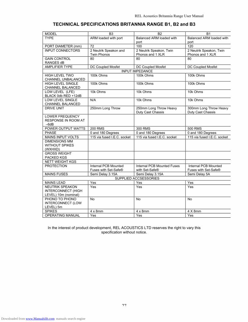
TECHNICAL SPECIFICATIONS BRITANNIA RANGE B1, B2 and B3
MODEL B3 B2 B1TYPE ARM loaded with port Balanced ARM loaded with
portBalanced ARM loaded withport
PORT DIAMETER (mm) 72 100 120INPUT CONNECTORS 2 Neutrik Speakon and
Twin Phonos2 Neutrik Speakon, TwinPhonos and 1 XLR
2 Neutrik Speakon, TwinPhonos and 1 XLR
GAIN CONTROLRANGES dB
80 80 80
AMPLIFIER TYPE DC Coupled Mosfet DC Coupled Mosfet DC Coupled MosfetINPUT IMPEDANCE
HIGH LEVEL TWOCHANNEL UNBALANCED
100k Ohms 100k Ohms 100k Ohms
HIGH LEVEL SINGLECHANNEL BALANCED
100k Ohms 100k Ohms 100k Ohms
LOW LEVEL (LFE)BLACK 0db RED +12dB
10k Ohms 10k Ohms 10k Ohms
LOW LEVEL SINGLECHANNEL BALANCED
N/A 10k Ohms 10k Ohms
DRIVE UNIT 250mm Long Throw 250mm Long Throw HeavyDuty Cast Chassis
300mm Long Throw HeavyDuty Cast Chassis
LOWER FREQUENCYRESPONSE IN ROOM AT –6dBPOWER OUTPUT WATTS 200 RMS 300 RMS 500 RMSPHASE 0 and 180 Degrees 0 and 180 Degrees 0 and 180 DegreesMAINS INPUT VOLTS 115 via fused I.E.C. socket 115 via fused I.E.C. socket 115 via fused I.E.C. socketDIMENSIONS MMWITHOUT SPIKES(WXHXD)GROSS WEIGHTPACKED KGSNETT WEIGHT KGSPROTECTION Internal PCB Mounted
Fuses with Set-Safe®Internal PCB Mounted Fuseswith Set-Safe®
Internal PCB MountedFuses with Set-Safe®
MAINS FUSES Semi Delay 3.15A Semi Delay 3.15A Semi Delay 5ASUPPLIED ACCSESSORIES
MAINS LEAD Yes Yes YesNEUTRIK SPEAKONINTERCONNECT (HIGHLEVEL) 10m (nominal)
Yes Yes Yes
PHONO TO PHONOINTERCONNECT (LOWLEVEL) 5m
No No No
SPIKES 4 x 8mm 4 x 8mm 4 X 8mmOPERATING MANUAL Yes Yes Yes
In the interest of product development, REL ACOUSTICS LTD reserves the right to vary thisspecification without notice.
Downloaded from www.Manualslib.com manuals search engine

REL Acoustics Britannia Range User Manual
28
Downloaded from www.Manualslib.com manuals search engine

REL Acoustics Britannia Range User Manual
29
Downloaded from www.Manualslib.com manuals search engine