büro für tragwerksplanung und ingenieurbau vom …...2018/11/05 · this structural report is set...
TRANSCRIPT
Büro für Tragwerksplanung und Ingenieurbau
vom Felde + Keppler GmbH & Co. KG
Lütticher Straße 10-12 Telefon: 0241 / 70 96 96 52064 Aachen Telefax: 0241 / 70 96 46 www.vom-felde.de [email protected]
Structural Report F45
Date 05/11/2018 for the system by
Global Truss Furong Industrial Area Shajing Town Baoan District Shenzen China Compiled by: Aachen, 05th November 2018
This Structural Report includes pages 1 - 50 This Structural Report is set up exclusively for the company Global Truss. Forwarding to third parties only with the author’s approval.
17433
Büro für Tragwerksplanung und Ingenieurbau
vom Felde + Keppler GmbH & Co. KG
Lütticher Straße 10-12
52064 Aachen
Telefon: 0241 / 70 96 96
Telefax: 0241 / 70 96 46
buero@vom- fe lde.de
TABLE OF CONTENTS
1 PRELIMINARY NOTES ....................................................................................................................................1
1.1 Basics .........................................................................................................................................................1 1.2 Materials ....................................................................................................................................................1 1.3 General remarks ........................................................................................................................................1 1.4 Geometry and loadings ..............................................................................................................................2
2 SYSTEM............................................................................................................................................................6 3 SECTION- AND MATERIAL PROPERTIES ....................................................................................................7 4 ALLOWABLE LOADING SINGLE COMPONENTS ....................................................................................... 10 5 ALLOWABLE LOADING SINGLE SPAN GIRDER ........................................................................................ 16
5.1 Center chords at bottom .......................................................................................................................... 16 5.2 Outer chords + bracing uniformly distributed load (UDL) ....................................................................... 27
6 SUMMARY OF RESULTS ............................................................................................................................. 42
6.1 Allowable loadings: .................................................................................................................................. 42 6.2 Deflections at max. allowable loadings: .................................................................................................. 48
ANNEXES Drawings F45
Büro für Tragwerksplanung und Ingenieurbau
vom Felde + Keppler GmbH & Co. KG
1
Lütticher Straße 10-12
52064 Aachen
Telefon: 0241 / 70 96 96
Telefax: 0241 / 70 96 46
buero@vom- fe lde.de
1 PRELIMINARY NOTES
1.1 Basics
The currently applicable regulations and standards, in particular: DIN EN 1991-1 Actions on structures (Eurocode 1) DIN EN 13814 Fairground and amusement park machinery and structures DIN EN 13782 Temporary Structures – Tents DIN EN 1993-1 Design of steel structures DIN EN 1999-1 Design of aluminium structures
1.2 Materials
Tubes Aluminium EN AW-6082 T6 Bolts Güte mid. 8.8 (grade min. 10.9)
1.3 General remarks
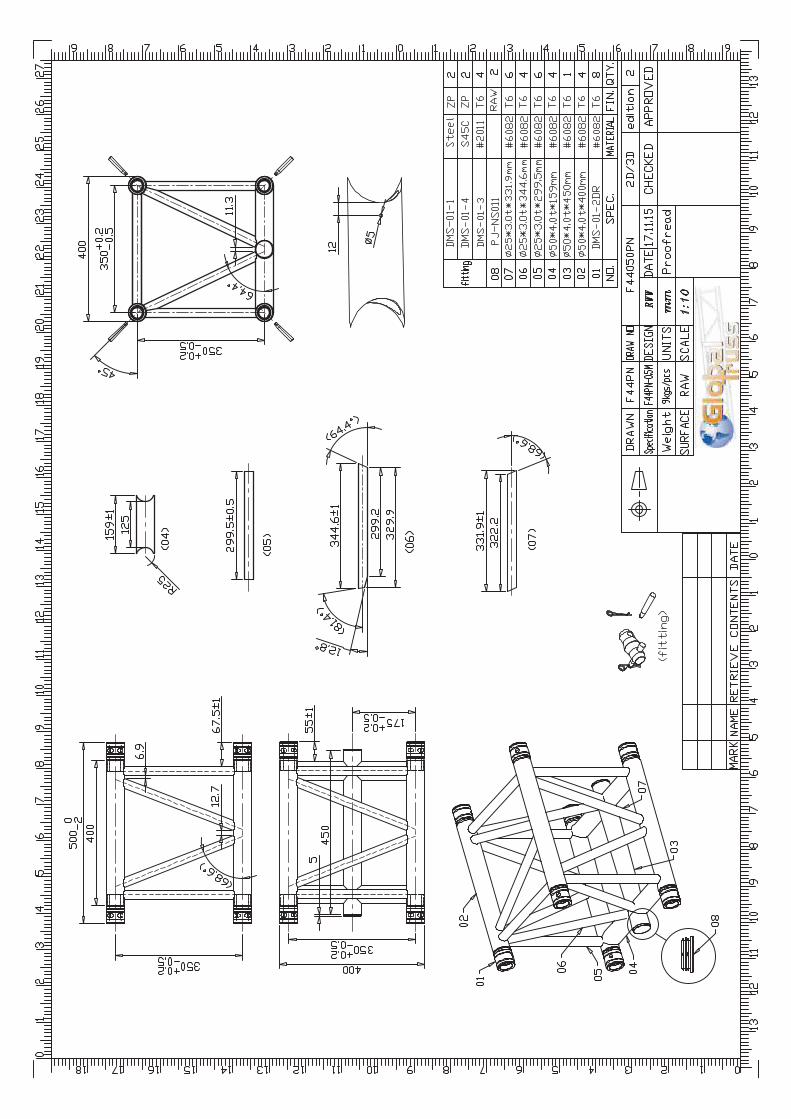
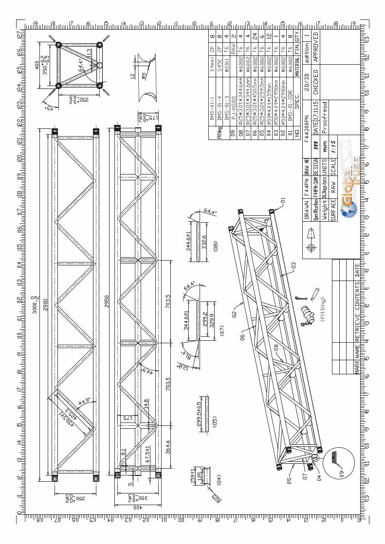
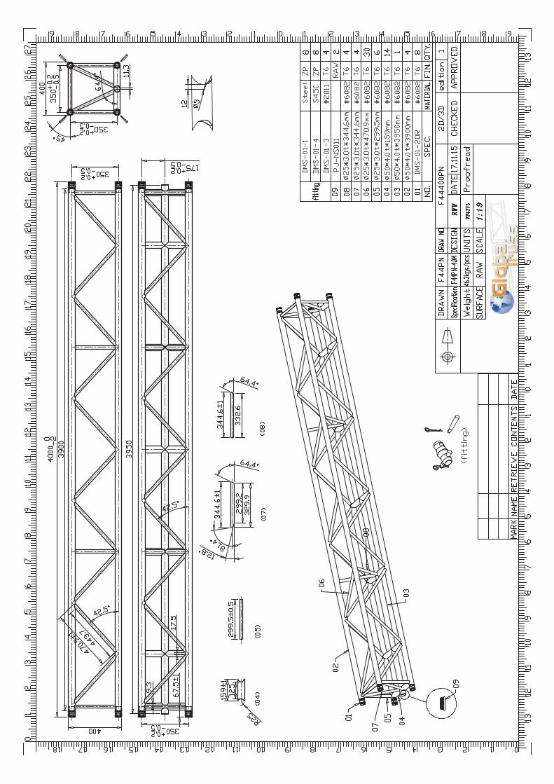
The truss system is part of a "modular construction system" with the different truss lengths 500mm, 1000mm, 1500mm, 2000mm, 2500mm, 3000mm, 3500mm, 4000mm, 4500mm and 5000mm. The Trusses consist of 2 upper and 3 lower main chords (round tube 50 x 4mm), which are arranged in a quadratic shape. The center chord at the bottom is connected to the outer chords by cross tubes (round tube 50 x 4mm). The trusses also consist of welded diagonal bracings (round tube 25 x 3mm). The truss type F44-P is stiffened by diagonal bracings at the top and at both vertical sides. The distance between system lines of the mainchords is 35 cm in vertical- and 35 cm in horizontal direction. The trusses are connected at the 4 outer mainchords with couplers consisting of female fittings, connectors and bolts. The center chord of the bottom is not connected with couplers. The loads are applied acc. chapter 1.4. The allowable loads are listed in tables (see chapter 6). The verification of the single parts is done according the safety concept of EN 1990 with a partial safety factor of the loading side of 1.50 for payloads. For applications which can be calculated on the basis of other codes, the partial safety factors can be adjusted (for example temporary structures acc. EN 13814, yF = 1.35 for payloads). To use the resulting allowable loads with British Standard (BS) and ANSI, the allowable loads listed in tables have to be multiplied by 0.85
Büro für Tragwerksplanung und Ingenieurbau
vom Felde + Keppler GmbH & Co. KG
2
Lütticher Straße 10-12
52064 Aachen
Telefon: 0241 / 70 96 96
Telefax: 0241 / 70 96 46
buero@vom- fe lde.de
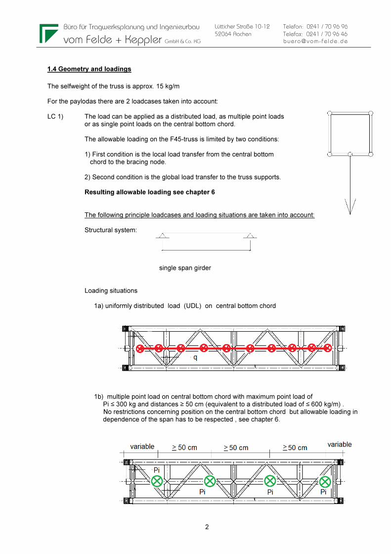
1.4 Geometry and loadings
The selfweight of the truss is approx. 15 kg/m For the paylodas there are 2 loadcases taken into account: LC 1) The load can be applied as a distributed load, as multiple point loads or as single point loads on the central bottom chord. The allowable loading on the F45-truss is limited by two conditions: 1) First condition is the local load transfer from the central bottom chord to the bracing node. 2) Second condition is the global load transfer to the truss supports. Resulting allowable loading see chapter 6 The following principle loadcases and loading situations are taken into account: Structural system: single span girder Loading situations 1a) uniformly distributed load (UDL) on central bottom chord 1b) multiple point load on central bottom chord with maximum point load of Pi ≤ 300 kg and distances ≥ 50 cm (equivalent to a distributed load of ≤ 600 kg/m) . No restrictions concerning position on the central bottom chord but allowable loading in dependence of the span has to be respected , see chapter 6.

Büro für Tragwerksplanung und Ingenieurbau
vom Felde + Keppler GmbH & Co. KG
3
Lütticher Straße 10-12
52064 Aachen
Telefon: 0241 / 70 96 96
Telefax: 0241 / 70 96 46
buero@vom- fe lde.de
P
l/2 l/2
P P
l/3l/3 l/3
PPPPPP PPPPPPPPPPPP
l/4 l/4 l/4 l/4
l/5
P P P P
l/5 l/5 l/5 l/5
1c) Single point loads on central bottom chord Single-load in 1/2 point Single-load in 1/3 points Single-load in 1/4 points Single-load in 1/5 points

Büro für Tragwerksplanung und Ingenieurbau
vom Felde + Keppler GmbH & Co. KG
4
Lütticher Straße 10-12
52064 Aachen
Telefon: 0241 / 70 96 96
Telefax: 0241 / 70 96 46
buero@vom- fe lde.de
q
l
P
l/2 l/2
P P
l/3l/3 l/3
PPPPPP PPPPPPPPPPPP
l/4 l/4 l/4 l/4
l/5
P P P P
l/5 l/5 l/5 l/5
LC 2) The load can be applied as a distributed load or as single point loads on the side chords: The following principle loadcases and loading situations are taken into account: Structural system: single span girder Loading situations 2a) uniformly distributed load (UDL) on side chords Uniformly distributed load (UDL) 2b) Single point loads on central bottom chord Single-load in 1/2 point Single-load in 1/3 points Single-load in 1/4 points Single-load in 1/5 points

Büro für Tragwerksplanung und Ingenieurbau
vom Felde + Keppler GmbH & Co. KG
5
Lütticher Straße 10-12
52064 Aachen
Telefon: 0241 / 70 96 96
Telefax: 0241 / 70 96 46
buero@vom- fe lde.de
For the support or suspension there are the following possibilities: The trusses are connected at the 4 outer mainchords with couplers consisting of female fittings, connectors and bolts. The center chord of the bottom is not connected with couplers.
No coupler! No coupler!

Büro für Tragwerksplanung und Ingenieurbau
vom Felde + Keppler GmbH & Co. KG
6
Lütticher Straße 10-12
52064 Aachen
Telefon: 0241 / 70 96 96
Telefax: 0241 / 70 96 46
buero@vom- fe lde.de
2 SYSTEM
Drawings F45 see annex

Büro für Tragwerksplanung und Ingenieurbau
vom Felde + Keppler GmbH & Co. KG
7
Lütticher Straße 10-12
52064 Aachen
Telefon: 0241 / 70 96 96
Telefax: 0241 / 70 96 46
buero@vom- fe lde.de
3 SECTION- AND MATERIAL PROPERTIES No coupler! No coupler!
Querschnittswerte Rohre / properties Tubes
D t A I Wel i
[mm] [mm] [cm²] [cm4] [cm³] [cm]
Gurtrohre / main chords 50,0 4 5,78 15,41 6,16 1,63
vertikal Diagonalen / Bracing 25 3 2,07 1,28 1,02 0,79
horizontal Diagonalen / Bracing 25 3 2,07 1,28 1,02 0,79
Geometrie Traverse / truss geometry
Achsabstand Gurtrohre vertikal ev 35 [cm]
distance axes main chords horizontal eh 35 [cm]
min. Neigung Diagonalen vertikal α 41 [°]
min. gradient bracing horizontal α 41 [°]
Kennwerte Gesamttraverse / properties truss-Section
A = 4 x AG = 23,12 [cm²]
Iyy = 4 x IG + 4 x AG x (ev/2)² = 7142,77 [cm4]
Izz = 4 x IG + 4 x AG x (eh/2)² = 7142,77 [cm4]
It = Näherung aus Erfahrungsw erten = 1666,38 [cm4]
iy = (Iyy/A) 1/2 = 17,58 [cm]
iz = (Izz/A) 1/2 = 17,58 [cm]
Index G : Querschnittseigenschaft Gurtrohr
section properties main chord

Büro für Tragwerksplanung und Ingenieurbau
vom Felde + Keppler GmbH & Co. KG
8
Lütticher Straße 10-12
52064 Aachen
Telefon: 0241 / 70 96 96
Telefax: 0241 / 70 96 46
buero@vom- fe lde.de
Material properties
Gurtrohre + Diagonalen EN AW 6082 T6 (AlMgSi1)
chords and bracing
zulässige Spannungen nach EN-1999-1-1 / allowable stress acc. to EN-1999-1-1
Teilsicherheitsbeiwerte Material / partial safety factors material
YM1= 1,10 Beulklasse / BC= A
YM2= 1,25
0,2%-Dehngrenze / 0,2%-Proof Strength Zugfestigkeit / ultimate tensile strength
fo t≤5mm= 250 [N/mm²] fu t≤5mm= 290 [N/mm²]
fo t>5mm= 260 [N/mm²] fu t>5mm= 310 [N/mm²]
fo,haz= 125 [N/mm²] fu,haz= 185 [N/mm²]
Festigkeit der Schweißnaht fw= 190 [N/mm²]
Strength of w elding seams
Faktor für die WEZ-Werte beim WIG-Schweißen: 0,8
Factor for HAZ-values for TIG-w elding:
Bolzen / Bolt 42 CrMo (8.8)
Verbinder / Connector EN AW 2011 T6 (AlCuBiPb)
0,2%-Dehngrenze / 0,2%-Proof Strength Zugfestigkeit / ultimate tensile strength
fo> 230 [N/mm²] fu> 310 [N/mm²]
Hülse / Female fitting EN AW 6082 T6
zulässige Spannungen nach EN-1999-1-1 / allowable stress acc. to EN-1999-1-1
Teilsicherheitsbeiwerte Material / partial safety factors material
YM1= 1,10
YM2= 1,25
0,2%-Dehngrenze / 0,2%-Proof Strength Zugfestigkeit / ultimate tensile strength
fo= 250 [N/mm²] fu= 290 [N/mm²]
Büro für Tragwerksplanung und Ingenieurbau
vom Felde + Keppler GmbH & Co. KG
9
Lütticher Straße 10-12
52064 Aachen
Telefon: 0241 / 70 96 96
Telefax: 0241 / 70 96 46
buero@vom- fe lde.de
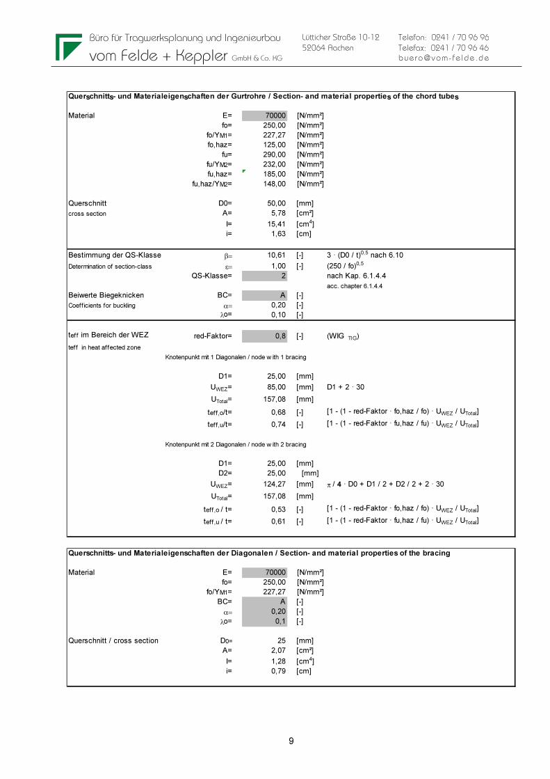
Querschnitts- und Materialeigenschaften der Gurtrohre / Section- and material properties of the chord tubes
Material E= 70000 [N/mm²]
fo= 250,00 [N/mm²]
fo/YM1= 227,27 [N/mm²]
fo,haz= 125,00 [N/mm²]
fu= 290,00 [N/mm²]
fu/YM2= 232,00 [N/mm²]
fu,haz= 185,00 [N/mm²]
fu,haz/YM2= 148,00 [N/mm²]
Querschnitt D0= 50,00 [mm]
cross section A= 5,78 [cm²]
I= 15,41 [cm4]
i= 1,63 [cm]
Bestimmung der QS-Klasse β= 10,61 [-] 3 · (D0 / t)0,5 nach 6.10
Determination of section-class ε= 1,00 [-] (250 / fo)0,5
QS-Klasse= 2 nach Kap. 6.1.4.4
acc. chapter 6.1.4.4
Beiwerte Biegeknicken BC= A [-]
Coefficients for buckling α= 0,20 [-]
λo= 0,10 [-]
teff im Bereich der WEZ red-Faktor= 0,8 [-] (WIG TIG)
teff in heat affected zone
Knotenpunkt mit 1 Diagonalen / node w ith 1 bracing
D1= 25,00 [mm]
UWEZ= 85,00 [mm] D1 + 2 · 30
UTotal= 157,08 [mm]
teff,o/t= 0,68 [-] [1 - (1 - red-Faktor · fo,haz / fo) · UWEZ / UTotal]
teff,u/t= 0,74 [-] [1 - (1 - red-Faktor · fu,haz / fu) · UWEZ / UTotal]
Knotenpunkt mit 2 Diagonalen / node w ith 2 bracing
D1= 25,00 [mm]
D2= 25,00 [mm]
UWEZ= 124,27 [mm] π / 4 · D0 + D1 / 2 + D2 / 2 + 2 · 30
UTotal= 157,08 [mm]
teff,o / t= 0,53 [-] [1 - (1 - red-Faktor · fo,haz / fo) · UWEZ / UTotal]
teff,u / t= 0,61 [-] [1 - (1 - red-Faktor · fu,haz / fu) · UWEZ / UTotal]
Querschnitts- und Materialeigenschaften der Diagonalen / Section- and material properties of the bracing
Material E= 70000 [N/mm²]
fo= 250,00 [N/mm²]
fo/YM1= 227,27 [N/mm²]
BC= A [-]
α= 0,20 [-]
λo= 0,1 [-]
Querschnitt / cross section D0= 25 [mm]
A= 2,07 [cm²]
I= 1,28 [cm4]
i= 0,79 [cm]

Büro für Tragwerksplanung und Ingenieurbau
vom Felde + Keppler GmbH & Co. KG
10
Lütticher Straße 10-12
52064 Aachen
Telefon: 0241 / 70 96 96
Telefax: 0241 / 70 96 46
buero@vom- fe lde.de
4 ALLOWABLE LOADING SINGLE COMPONENTS Outer chords at top and bottom Gurtrohr im Bereich der WEZ an der Kupplung
main chord in heat affected zone at coupler
NRd =A x 0,8* x fu,haz / YM2= 68,44 [kN] *(WIG TIG)
örtliche Schweißnaht nach Kap. 6.2.9.3 (1)
local w elding seam acc. chapter 6.2.9.3 (1)
Gurtrohr im Bereich der WEZ
main chord in heat affected zone Knotenpunkt mit 1 Diagonalen / node w ith 1 bracing
NRd = Aeff x fo / YM1= 88,72 [kN] örtliche Schweißnaht nach Kap. 6.2.9.3 (2)
(mit Aeff= teff,o / t x A) local w elding seam acc. Chapter 6.2.9.3 (2)
Knotenpunkt mit 2 Diagonalen / node w ith 2 bracing
NRd = Aeff x fo / YM1= 69,01 [kN] örtliche Schweißnaht nach Kap. 6.2.9.3 (2)
(mit Aeff= teff,o / t x A) local w elding seam acc. Chapter 6.2.9.3 (2)
Knicken Gurtrohr zw. Knoten sk= 80,00 [cm]
mit 1 Diagonale in der Mitte
buckling main chord bew teen nodes
w ith 1 bracing in the middle Ncr= 166,30 [kN]
λ*= 0,93 [-]
φ= 1,02 [-]
X= 0,70 [-]
A1= 3,74 [cm²] nach Tab. 6.5
κ= 0,84 [-] acc. table 6.5
NRd = X x κ x Aeff x fo / YM1= 77,82 [kN] nach Gl. 6.49
(mit Aeff=A für QSK 1,2 und 3, s. EN 1999-1-1 Kap. 6.3.1.1) acc. equation 6.49
Knicken Gurtrohr zw. Knoten sk= 80,00 [cm]
ohne Diagonale in der Mitte
buckling main chord bew teen nodes
w ithout bracing in the middle Ncr= 166,30 [kN]
λ*= 0,93 [-]
φ= 1,02 [-]
X= 0,70 [-]
NRd = X x A x fo / YM1= 92,12 [kN] nach Gl. 6.49
acc. equation 6.49
Schweißnaht zwischen Gurtrohr und Hülse
welding seam betw een chord and female conical coupler
fw= 190,00 [N/mm²]
Ymw= 1,25 [-]
NRd = A x fw / YM1= 87,86 [kN] nach Gl. 8.29
acc. equation 8.29 relevant for main chord tubes: NRdG = 68,44 kN

Büro für Tragwerksplanung und Ingenieurbau
vom Felde + Keppler GmbH & Co. KG
11
Lütticher Straße 10-12
52064 Aachen
Telefon: 0241 / 70 96 96
Telefax: 0241 / 70 96 46
buero@vom- fe lde.de
Bending of the center chord at the bottom and of the cross tubes:
Lokale Biegung unteres inneres Gurtrohr Knotenpunkt mit Querrohr
Local bending of low er inner chord w ith lateral tube
örtliche Schweißnaht nach Kap. 6.2.9.3 (2)
local w elding seam acc. Chapter 6.2.9.3 (2)
α= 0,55 [-] nach Tab. 6.4
Nebenrechnung QS-Kl. 3 D= 50,0 [mm]
Auxiliary calculation for class 3 red-Faktor= 0,8 [-] (WIG TIG)
ρo,haz= 0,5 [-] fo,haz / fo
to,eff= 1,60 [mm] teff,o / t · t
Wel,haz= π x R² x to,eff= 2,66 [cm³] mit R = D / 2 - t / 2
Wel= 6,16 [cm³]
Wpl,haz= 4 x R² x to,eff= 3,39 [cm³] mit R = D / 2 - t / 2
β3= 18 nach Kap. 6.1.4.4nach Kap. 6.1.4.4
β2= 13 nach Kap. 6.1.4.4nach Kap. 6.1.4.4
α,3w= 0,61 [-]
MoRd = α · Wel · fo / yM1= 76,95 [kNcm] nach Gl. 6.24
acc. equation 6.24
Bracing
Diagonale im Bereich der WEZ
bracing in heat affected zone
NRd = A x 0,8* x fu,haz / YM2= 24,55 [kN] *(WIG TIG)
örtliche Schweißnaht nach Kap. 6.2.9.3 (1)
local w elding seam acc. chapter 6.2.9.3 (1)
Knicken Diagonale sk= 45,00 [cm]
buckling bracing
Ncr= 43,59 [kN]
λ*= 1,09 [-]
φ= 1,19 [-]
X= 0,60 [-]
NRd = X x AG x fo / YM1= 28,07 [kN] nach Gl. 6.49
acc. equation 6.49
Schweißnaht zwischen Diagonale und Gurtrohr
welding seam betw een chord and female conical coupler
fw= 190,00 [N/mm²]
Ymw= 1,25 [-]
NRd = A x fw / YM1= 31,52 [kN] nach Gl. 8.29
acc. equation 8.29 relevant for bracing tubes: NRdD = 24,55 kN

Büro für Tragwerksplanung und Ingenieurbau
vom Felde + Keppler GmbH & Co. KG
12
Lütticher Straße 10-12
52064 Aachen
Telefon: 0241 / 70 96 96
Telefax: 0241 / 70 96 46
buero@vom- fe lde.de
Allowable normal force at coupler: Bolzen / Bolt
Material / material (8.8) fy,bk= 64,00 [kN/cm²]
fu,bk= 80,00 [kN/cm²]
Geometrie / geometry Db= 1,08 [cm]
Ab= 0,91 [cm²]
zul Normalkraft aus Abscheren n. EN 1999-1-1
allow able loading due to shearing acc. to EN 1999-1-1
NRd = 2 x 0,60 x Ab x fub,k / 1,25= 69,71 [kN]
Verbinder / Connector
Material / material EN AW 2011 (AlCuBiPb F37)
Geometrie / geometry Dm= 29 [mm]
Lochleibung in Verbinder fu / YM2= 248,00 [N/mm²]
Bearing stress in connector do= 11 [mm]
t= 29 [mm]
e1= 17,1 [mm]
αb= 0,52 [-]
e2= 14,5 [mm]
k1= 1,99090909 [-]
NRd = k1 x αb x fu x d x t / YM2= 81,62 [kN]
Nachweis Restquerschnitt auf Zug
Remaining section under tension
NRd = 0,9 x A,net x fu / YM2= 76,23 [kN]
Hülse / Female Fitting
Geometrie / geometry DH= 50 [mm]
Di-1= 29 [mm]
Di-2= 35 [mm]
Di-m= 32 [mm]
Lochleibung in Hülse fu / YM2= 232 [N/mm²]
Bearing stress in female fitting do= 13 [mm]
t = DH - Di-m= 18 [mm]
e1> 23 [mm]
αb= 0,59
e2> 20 [mm]
k1= 2,5
NRd = k1 x αb x fu x d x t / YM2= 80,04 [kN]
The allowable normal force of the coupler is not relevant compared to the allowable normal force of the tube
(NRdG = 68,44 kN < 69,71 kN).

Büro für Tragwerksplanung und Ingenieurbau
vom Felde + Keppler GmbH & Co. KG
13
Lütticher Straße 10-12
52064 Aachen
Telefon: 0241 / 70 96 96
Telefax: 0241 / 70 96 46
buero@vom- fe lde.de
Interaction bending and normal force at coupler of the outer chords
Verification of interaction bending and normal force at coupler
=> (NsdG / NRdG)1,3 + (MsdG / MRdG) < 1,0 mit NsdG = Nsd / 4 + Msd / (2 · 0,35 m)
und MsdG = 0,25 ⋅ Qsd ⋅ 8,0 cm = 2,0 cm ⋅ Qsd
=> a = factor for cantilever at the coupler = 2,0 cm
Nsd, Msd und Qsd: global internal forces in the truss (in kN resp. kNm)
The global internal forces include the following safety factors acc. Eurocode: selfweight of the truss: yF = 1,35 Net load on the truss: yF = 1,50 NRdG = allowable loading of the chord in the heat affected zone (see following table): Gurtrohr im Bereich der WEZ an der Kupplung
main chord in heat affected zone at coupler
NRd =A x 0,8* x fu,haz / YM2= 68,44 [kN] *(WIG TIG)
örtliche Schweißnaht nach Kap. 6.2.9.3 (1)
local w elding seam acc. chapter 6.2.9.3 (1)
MRdG = MuRd (see following table): Lokale Biegung Gurtrohr Knotenpunkt vollst. in WEZ
Local bending of chord
örtliche Schweißnaht nach Kap. 6.2.9.3 (1)
local w elding seam acc. Chapter 6.2.9.3 (1)
D= 50 [mm]
red-Faktor= 0,8 [-] (WIG TIG)
ρo,haz= 0,64 [-] fu,haz / fu
tu,eff= 2,04 [mm] red-Faktor · ρu,haz · t
Wnet= π x R² x tu,eff= 3,39 [cm³] mit R = D / 2 - t / 2
MuRd = Wnet · fu / yM2= 78,71 [kNcm] nach Gl. 6.24
acc. equation 6.24

Büro für Tragwerksplanung und Ingenieurbau
vom Felde + Keppler GmbH & Co. KG
14
Lütticher Straße 10-12
52064 Aachen
Telefon: 0241 / 70 96 96
Telefax: 0241 / 70 96 46
buero@vom- fe lde.de
The following 4 cases are taken into account. 1. Verification of the center chords at the bottom at UDL-loads or multiple single point loads (LC 1a and 1b)
The loads at center chord at the bottom are loaded at the worst points with multiple single point loads at a distance of 50 cm between each load. 2. Verification of the center chord at the bottom with single point loads (LC 1c) No requirements for position of coupler (see below). 3. Verification of the outer chords with uniformly distributed load (UDL) (LC 2a) The coupler is always located at the theoretically worst point. This results from the following extremum-calculation:
Note: For the determination of the worst position of the coupler, the exponent 1,3, for the relation of actual load to the allowable load is not taken into account with sufficient accuracy.
Msd (x) = qsd ⋅ L² / 8 - qsd ⋅ x² / 2
Qsd (x) = qsd ⋅ x
NRdG = 68,44 kN MRdG = 78,71 kNcm
M-Q Interaction Msd(x) / (2 ⋅ 0,35 · 68,44) + Qsd(x) ⋅ 2,0 / 78,71
Extreme value: d/dx σ (x) = 0
=> x = 2 ⋅ 0,35 ⋅ 68,44 ⋅ 2,0 / 78,71 = 1,217 m (from middle of span)
4. Verification of the side chords with single point loads (LC 2b) No requirements for position of coupler (Distance between load and coupler is e ≥ 9,5 cm, see below)

Büro für Tragwerksplanung und Ingenieurbau
vom Felde + Keppler GmbH & Co. KG
15
Lütticher Straße 10-12
52064 Aachen
Telefon: 0241 / 70 96 96
Telefax: 0241 / 70 96 46
buero@vom- fe lde.de
Summary Following points are relevant for the determination of the allowable loads: 1. Allowable bending moment of the center chord at the bottom and the cross tubes (MRdG) => MRdG = 76,95 kNcm
2. Allowable normal force in main chord (NRdG) Main chord in heat affected zone at coupler is relevant => NRdG = 68,44 kN 3. Global shear force in truss (Q) Allowable normal force in diagonals at nodes is relevant => NRdD = 24,55 kN
zul shear force from QRd / (2 ⋅ sin 41 ̊ ) < 0,9 ⋅ NRdD
* 10% reduction because of minor stresses
=> allow. QRd = 0,9 ⋅ 24,55 ⋅ 2 ⋅ sin 41 ̊ => QRd = 28,99 kN
4. Interaction bending and normal force at coupler see page 13

Büro für Tragwerksplanung und Ingenieurbau
vom Felde + Keppler GmbH & Co. KG
16
Lütticher Straße 10-12
52064 Aachen
Telefon: 0241 / 70 96 96
Telefax: 0241 / 70 96 46
buero@vom- fe lde.de
5 ALLOWABLE LOADING SINGLE SPAN GIRDER
5.1 Center chords at bottom
Systems [cm]:
Loadings: Multiple point loads at a distance of 50 cm Pi = 3,0 kN see following pages Single point load (CPL or at 1/3-, 1/4- or 1/5-pts) Pi = 5,0 kN Calculation see following pages
Verification: Multplie point loads max MEd = 1,5 · 45 kNcm = 67,5 kNcm < MRd = 76,95 kNcm Single point load max MEd = 1,5 · 5 · 35 / 4 = 66 kNcm < MRd = 76,95 kNcm

Büro für Tragwerksplanung und Ingenieurbau
vom Felde + Keppler GmbH & Co. KG
27
Lütticher Straße 10-12
52064 Aachen
Telefon: 0241 / 70 96 96
Telefax: 0241 / 70 96 46
buero@vom- fe lde.de
q
l
5.2 Outer chords + bracing uniformly distributed load (UDL)
System: Loading qsd = psd + gsd (Net load + selfweight, incl. safety factors)
Normal force in chords: NRd > qsd ⋅ L² / 8 / (n ⋅ b)
=> qsd < NRd ⋅ (n ⋅ b) ⋅ 8 / L²
=> zul p = (NRd ⋅ (n ⋅ b) ⋅ 8 / L² - gsd) / yF
Normal force in bracing: QRd > qsd ⋅ L / 2
=> qsd < QRd ⋅ 2 / L
=> zul p = (QRd ⋅ 2 / L - gsd) / yF
Interaction at coupler: Verification of interaction bending and normal force at coupler by an iterative method.
=> (NsdG / NRdG)1,3 + (MsdG / MRdG) < 1,0 The coupler is located at e = 1,217 m from the middle of the span (theoretically worst point, see extremum- calculation in chapter 4) Center chord at bottom: zul p ≤ 6,0 kN/m Limit of deflection: Limit of deflection max. u = L / f => zul p = (L / f) / (5/384 · L4 / E / Iyy) - g 3 different limitations are taken into account: max. u = L / 100 max. u = L / 200 max. u = L / 300
Loading tables: see following pages

Büro für Tragwerksplanung und Ingenieurbau
vom Felde + Keppler GmbH & Co. KG
28
Lütticher Straße 10-12
52064 Aachen
Telefon: 0241 / 70 96 96
Telefax: 0241 / 70 96 46
buero@vom- fe lde.de
Uniformly distributed load UDL
NRd QRd Interaction at coupler Deflection L/100
L [m] zul q [kN/m] zul q [kN/m] zul q [kN/m] zul q [kN/m]
4,00 15,84 9,53 12,60 59,85
5,00 10,09 7,60 8,75 30,57
6,00 6,96 6,31 6,31 17,63
7,00 5,08 5,39 4,73 11,05
8,00 3,86 4,70 3,65 7,35
9,00 3,02 4,16 2,89 5,12
10,00 2,42 3,73 2,34 3,69
11,00 1,98 3,38 1,92 2,74
12,00 1,64 3,09 1,60 2,07
13,00 1,38 2,84 1,35 1,60
14,00 1,17 2,63 1,15 1,25
15,00 1,00 2,44 0,99 0,99
16,00 0,86 2,28 0,85 0,79
17,00 0,75 2,14 0,74 0,63
18,00 0,66 2,01 0,65 0,51
19,00 0,57 1,90 0,57 0,41
20,00 0,51 1,80 0,50 0,33
21,00 0,45 1,71 0,44 0,27
22,00 0,39 1,62 0,39 0,21
23,00 0,35 1,55 0,35 0,17
24,00 0,31 1,48 0,31 0,13
allowable load as a function of
zulässige Belastung in Abhängigkeit von
Note: If the load ist applied at the center bottom chord (LC1) it has to be ≤ 6,0 kN/m
Uniformly distributed load UDL
NRd QRd Interaction at coupler Deflection L/200
L [m] zul q [kN/m] zul q [kN/m] zul q [kN/m] zul q [kN/m]
4,00 15,84 9,53 12,60 29,85
5,00 10,09 7,60 8,75 15,21
6,00 6,96 6,31 6,31 8,74
7,00 5,08 5,39 4,73 5,45
8,00 3,86 4,70 3,65 3,60
9,00 3,02 4,16 2,89 2,49
10,00 2,42 3,73 2,34 1,77
11,00 1,98 3,38 1,92 1,29
12,00 1,64 3,09 1,60 0,96
13,00 1,38 2,84 1,35 0,73
14,00 1,17 2,63 1,15 0,55
15,00 1,00 2,44 0,99 0,42
16,00 0,86 2,28 0,85 0,32
17,00 0,75 2,14 0,74 0,24
18,00 0,66 2,01 0,65 0,18
19,00 0,57 1,90 0,57 0,13
20,00 0,51 1,80 0,50 0,09
21,00 0,45 1,71 0,44 0,06
22,00 0,39 1,62 0,39 0,03
allowable load as a function of
zulässige Belastung in Abhängigkeit von
Note: If the load ist applied at the center bottom chord (LC1) it has to be ≤ 6,0 kN/m

Büro für Tragwerksplanung und Ingenieurbau
vom Felde + Keppler GmbH & Co. KG
29
Lütticher Straße 10-12
52064 Aachen
Telefon: 0241 / 70 96 96
Telefax: 0241 / 70 96 46
buero@vom- fe lde.de
Uniformly distributed load UDL
NRd QRd Interaction at coupler Deflection L/300
L [m] zul q [kN/m] zul q [kN/m] zul q [kN/m] zul q [kN/m]
4,00 15,84 9,53 12,60 19,85
5,00 10,09 7,60 8,75 10,09
6,00 6,96 6,31 6,31 5,78
7,00 5,08 5,39 4,73 3,58
8,00 3,86 4,70 3,65 2,35
9,00 3,02 4,16 2,89 1,61
10,00 2,42 3,73 2,34 1,13
11,00 1,98 3,38 1,92 0,81
12,00 1,64 3,09 1,60 0,59
13,00 1,38 2,84 1,35 0,43
14,00 1,17 2,63 1,15 0,32
15,00 1,00 2,44 0,99 0,23
16,00 0,86 2,28 0,85 0,16
17,00 0,75 2,14 0,74 0,11
18,00 0,66 2,01 0,65 0,07
19,00 0,57 1,90 0,57 0,04
20,00 0,51 1,80 0,50 0,01
allowable load as a function of
zulässige Belastung in Abhängigkeit von
Note: If the load ist applied at the center bottom chord (LC1) it has to be ≤ 6,0 kN/m

Büro für Tragwerksplanung und Ingenieurbau
vom Felde + Keppler GmbH & Co. KG
30
Lütticher Straße 10-12
52064 Aachen
Telefon: 0241 / 70 96 96
Telefax: 0241 / 70 96 46
buero@vom- fe lde.de
P
l/2 l/2
5.3 Outer chords + bracing single point load at 1/2-point
System: Loading Psd + gsd (Net load + selfweight, incl. safety factors)
Normal force in chords: NRd > (Psd ⋅ L / 4 + gsd · L² / 8) / (n ⋅ b)
=> Psd < [NRd ⋅ (n ⋅ b) - gsd ⋅ L² / 8] · 4 / L
=> zul P = [NRd ⋅ (n ⋅ b) - gsd ⋅ L² / 8] · 4 / L / yF
Normal force in bracing: QRd > Psd / 2 + gsd ⋅ L / 2
=> Psd < (QRd – gsd · L / 2) · 2 => zul P = (QRd – gsd · L / 2) · 2 / yF Interaction at coupler: Verification of interaction bending and normal force at coupler by an iterative method.
=> (NsdG / NRdG)1,3 + (MsdG / MRdG) < 1,0 The coupler is located at e = 0,095 m from the coupler Center chord at bottom: zul P ≤ 5,0 kN Limit of deflection: Limit of deflection max. u = L / f => zul P = [L / f - g · (5/384 · L4 / E / Iyy)] / (L³/48 / E / Iyy) 3 different limitations are taken into account: max. u = L / 100 max. u = L / 200 max. u = L / 300
Loading tables: see following pages

Büro für Tragwerksplanung und Ingenieurbau
vom Felde + Keppler GmbH & Co. KG
31
Lütticher Straße 10-12
52064 Aachen
Telefon: 0241 / 70 96 96
Telefax: 0241 / 70 96 46
buero@vom- fe lde.de
Single-load in 1/2point
Nrd Qrd Interaction at coupler Deflection L/100
0,095 = e [m]
L [m] zul P [kN] zul P [kN] zul P [kN] zul P [kN]
4,00 31,67 38,12 22,09 149,63
5,00 25,22 37,99 18,79 95,54
6,00 20,89 37,85 16,29 66,11
7,00 17,78 37,72 14,34 48,33
8,00 15,44 37,59 12,76 36,76
9,00 13,59 37,45 11,46 28,80
10,00 12,11 37,32 10,37 23,07
11,00 10,88 37,19 9,44 18,82
12,00 9,85 37,05 8,64 15,56
13,00 8,96 36,92 7,93 13,00
14,00 8,19 36,79 7,31 10,95
15,00 7,52 36,65 6,75 9,28
16,00 6,92 36,52 6,25 7,89
17,00 6,38 36,39 5,80 6,73
18,00 5,90 36,25 5,39 5,74
19,00 5,46 36,12 5,01 4,89
20,00 5,05 35,99 4,66 4,15
21,00 4,68 35,85 4,33 3,50
22,00 4,34 35,72 4,03 2,92
23,00 4,02 35,59 3,74 2,41
24,00 3,72 35,45 3,48 1,94
zulässige Belastung in Abhängigkeit von
allowable load as a function of
Note: If the load is applied at the center bottom chord (LC1) it has to be ≤ 5,0 kN
Single-load in 1/2point
Nrd Qrd Interaction at coupler Deflection L/200
0,095 = e [m]
L [m] zul P [kN] zul P [kN] zul P [kN] zul P [kN]
4,00 31,67 38,12 22,09 74,63
5,00 25,22 37,99 18,79 47,54
6,00 20,89 37,85 16,29 32,78
7,00 17,78 37,72 14,34 23,84
8,00 15,44 37,59 12,76 18,01
9,00 13,59 37,45 11,46 13,98
10,00 12,11 37,32 10,37 11,07
11,00 10,88 37,19 9,44 8,90
12,00 9,85 37,05 8,64 7,22
13,00 8,96 36,92 7,93 5,90
14,00 8,19 36,79 7,31 4,83
15,00 7,52 36,65 6,75 3,94
16,00 6,92 36,52 6,25 3,21
17,00 6,38 36,39 5,80 2,58
18,00 5,90 36,25 5,39 2,04
19,00 5,46 36,12 5,01 1,56
20,00 5,05 35,99 4,66 1,15
21,00 4,68 35,85 4,33 0,78
22,00 4,34 35,72 4,03 0,44
zulässige Belastung in Abhängigkeit von
allowable load as a function of
Note: If the load is applied at the center bottom chord (LC1) it has to be ≤ 5,0 kN

Büro für Tragwerksplanung und Ingenieurbau
vom Felde + Keppler GmbH & Co. KG
32
Lütticher Straße 10-12
52064 Aachen
Telefon: 0241 / 70 96 96
Telefax: 0241 / 70 96 46
buero@vom- fe lde.de
Single-load in 1/2point
Nrd Qrd Interaction at coupler Deflection L/300
0,095 = e [m]
L [m] zul P [kN] zul P [kN] zul P [kN] zul P [kN]
4,00 31,67 38,12 22,09 49,63
5,00 25,22 37,99 18,79 31,54
6,00 20,89 37,85 16,29 21,67
7,00 17,78 37,72 14,34 15,68
8,00 15,44 37,59 12,76 11,76
9,00 13,59 37,45 11,46 9,04
10,00 12,11 37,32 10,37 7,07
11,00 10,88 37,19 9,44 5,59
12,00 9,85 37,05 8,64 4,44
13,00 8,96 36,92 7,93 3,53
14,00 8,19 36,79 7,31 2,79
15,00 7,52 36,65 6,75 2,17
16,00 6,92 36,52 6,25 1,64
17,00 6,38 36,39 5,80 1,19
18,00 5,90 36,25 5,39 0,80
19,00 5,46 36,12 5,01 0,46
20,00 5,05 35,99 4,66 0,15
zulässige Belastung in Abhängigkeit von
allowable load as a function of
Note: If the load is applied at the center bottom chord (LC1) it has to be ≤ 5,0 kN

Büro für Tragwerksplanung und Ingenieurbau
vom Felde + Keppler GmbH & Co. KG
33
Lütticher Straße 10-12
52064 Aachen
Telefon: 0241 / 70 96 96
Telefax: 0241 / 70 96 46
buero@vom- fe lde.de
P P
l/3l/3 l/3
5.4 Outer chords + bracing single point load at 1/3-points
System: Loading Psd + gsd (Net load + selfweight, incl. safety factors)
Normal force in chords: NRd > (Psd ⋅ L / 3 + gsd · L² / 8) / (n ⋅ b)
=> Psd < [NRd ⋅ (n ⋅ b) - gsd ⋅ L² / 8] · 3 / L
=> zul P = [NRd ⋅ (n ⋅ b) - gsd ⋅ L² / 8] · 3 / L / yF
Normal force in bracing: QRd > Psd / 2 gsd ⋅ L / 2
=> Psd < (QRd – gsd · L / 2) => zul P = (QRd – gsd · L / 2) / yF Interaction at coupler: Verification of interaction bending and normal force at coupler by an iterative method.
=> (NsdG / NRdG)1,3 + (MsdG / MRdG) < 1,0 The coupler is located at e = 0,095 m from the coupler Center chord at bottom: zul P ≤ 5,0 kN Limit of deflection: Limit of deflection max. u = L / f => zul P = [L / f - g · (5/384 · L4/E/Iyy)] / (23/684·L³/E/Iyy) 3 different limitations are taken into account: max. u = L / 100 max. u = L / 200 max. u = L / 300 Loading tables: see following pages

Büro für Tragwerksplanung und Ingenieurbau
vom Felde + Keppler GmbH & Co. KG
34
Lütticher Straße 10-12
52064 Aachen
Telefon: 0241 / 70 96 96
Telefax: 0241 / 70 96 46
buero@vom- fe lde.de
Single-load in 1/3points
Nrd Qrd Interaction at coupler Deflection L/100
0,095 = e [m]
L [m] zul P [kN] zul P [kN] zul P [kN] zul P [kN]
4,00 23,75 19,06 13,58 87,83
5,00 18,91 18,99 11,93 56,08
6,00 15,67 18,93 10,57 38,81
7,00 13,34 18,86 9,45 28,37
8,00 11,58 18,79 8,53 21,58
9,00 10,20 18,73 7,74 16,90
10,00 9,08 18,66 7,07 13,54
11,00 8,16 18,59 6,49 11,04
12,00 7,38 18,53 5,98 9,13
13,00 6,72 18,46 5,52 7,63
14,00 6,14 18,39 5,12 6,43
15,00 5,64 18,33 4,76 5,45
16,00 5,19 18,26 4,43 4,63
17,00 4,79 18,19 4,12 3,95
18,00 4,42 18,13 3,85 3,37
19,00 4,09 18,06 3,59 2,87
20,00 3,79 17,99 3,36 2,43
21,00 3,51 17,93 3,14 2,05
22,00 3,26 17,86 2,93 1,71
23,00 3,02 17,79 2,74 1,41
24,00 2,79 17,73 2,56 1,14
allowable load as a function of
zulässige Belastung in Abhängigkeit von
Note: If the load is applied at the center bottom chord (LC1) it has to be ≤ 5,0 kN
Single-load in 1/3points
Nrd Qrd Interaction at coupler Deflection L/200
0,095 = e [m]
L [m] zul P [kN] zul P [kN] zul P [kN] zul P [kN]
4,00 23,75 19,06 13,58 43,81
5,00 18,91 18,99 11,93 27,90
6,00 15,67 18,93 10,57 19,24
7,00 13,34 18,86 9,45 13,99
8,00 11,58 18,79 8,53 10,57
9,00 10,20 18,73 7,74 8,21
10,00 9,08 18,66 7,07 6,50
11,00 8,16 18,59 6,49 5,22
12,00 7,38 18,53 5,98 4,24
13,00 6,72 18,46 5,52 3,46
14,00 6,14 18,39 5,12 2,83
15,00 5,64 18,33 4,76 2,32
16,00 5,19 18,26 4,43 1,88
17,00 4,79 18,19 4,12 1,51
18,00 4,42 18,13 3,85 1,20
19,00 4,09 18,06 3,59 0,92
20,00 3,79 17,99 3,36 0,67
21,00 3,51 17,93 3,14 0,46
22,00 3,26 17,86 2,93 0,26
zulässige Belastung in Abhängigkeit von
allowable load as a function of
Note: If the load is applied at the center bottom chord (LC1) it has to be ≤ 5,0 kN

Büro für Tragwerksplanung und Ingenieurbau
vom Felde + Keppler GmbH & Co. KG
35
Lütticher Straße 10-12
52064 Aachen
Telefon: 0241 / 70 96 96
Telefax: 0241 / 70 96 46
buero@vom- fe lde.de
Single-load in 1/3points
Nrd Qrd Interaction at coupler Deflection L/300
0,095 = e [m]
L [m] zul P [kN] zul P [kN] zul P [kN] zul P [kN]
4,00 23,75 19,06 13,58 29,13
5,00 18,91 18,99 11,93 18,51
6,00 15,67 18,93 10,57 12,72
7,00 13,34 18,86 9,45 9,20
8,00 11,58 18,79 8,53 6,90
9,00 10,20 18,73 7,74 5,31
10,00 9,08 18,66 7,07 4,15
11,00 8,16 18,59 6,49 3,28
12,00 7,38 18,53 5,98 2,61
13,00 6,72 18,46 5,52 2,07
14,00 6,14 18,39 5,12 1,63
15,00 5,64 18,33 4,76 1,27
16,00 5,19 18,26 4,43 0,96
17,00 4,79 18,19 4,12 0,70
18,00 4,42 18,13 3,85 0,47
19,00 4,09 18,06 3,59 0,27
20,00 3,79 17,99 3,36 0,09
allowable load as a function of
zulässige Belastung in Abhängigkeit von
Note: If the load is applied at the center bottom chord (LC1) it has to be ≤ 5,0 kN
Büro für Tragwerksplanung und Ingenieurbau
vom Felde + Keppler GmbH & Co. KG
36
Lütticher Straße 10-12
52064 Aachen
Telefon: 0241 / 70 96 96
Telefax: 0241 / 70 96 46
buero@vom- fe lde.de
PPPPPP PPPPPPPPPPPP
l/4 l/4 l/4 l/4
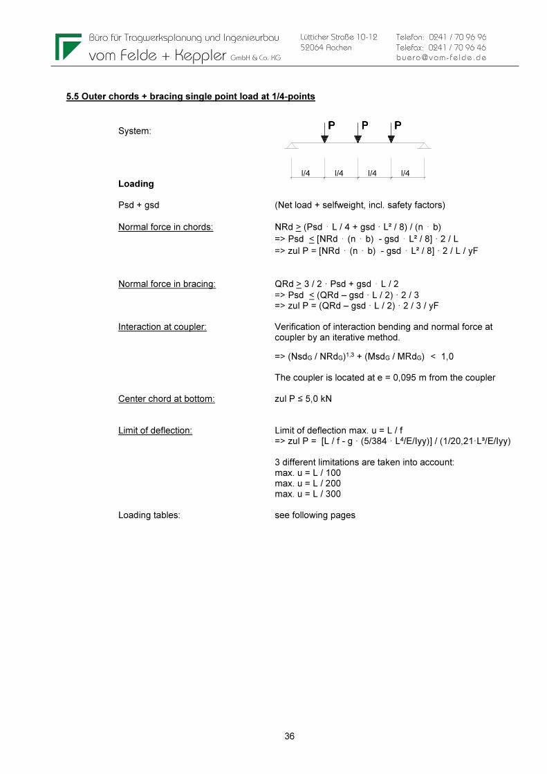
5.5 Outer chords + bracing single point load at 1/4-points
System: Loading Psd + gsd (Net load + selfweight, incl. safety factors)
Normal force in chords: NRd > (Psd ⋅ L / 4 + gsd · L² / 8) / (n ⋅ b)
=> Psd < [NRd ⋅ (n ⋅ b) - gsd ⋅ L² / 8] · 2 / L
=> zul P = [NRd ⋅ (n ⋅ b) - gsd ⋅ L² / 8] · 2 / L / yF
Normal force in bracing: QRd > 3 / 2 · Psd + gsd ⋅ L / 2
=> Psd < (QRd – gsd · L / 2) · 2 / 3 => zul P = (QRd – gsd · L / 2) · 2 / 3 / yF Interaction at coupler: Verification of interaction bending and normal force at coupler by an iterative method.
=> (NsdG / NRdG)1,3 + (MsdG / MRdG) < 1,0 The coupler is located at e = 0,095 m from the coupler Center chord at bottom: zul P ≤ 5,0 kN Limit of deflection: Limit of deflection max. u = L / f => zul P = [L / f - g · (5/384 · L4/E/Iyy)] / (1/20,21·L³/E/Iyy) 3 different limitations are taken into account: max. u = L / 100 max. u = L / 200 max. u = L / 300 Loading tables: see following pages

Büro für Tragwerksplanung und Ingenieurbau
vom Felde + Keppler GmbH & Co. KG
37
Lütticher Straße 10-12
52064 Aachen
Telefon: 0241 / 70 96 96
Telefax: 0241 / 70 96 46
buero@vom- fe lde.de
Single-load in 1/4points
Nrd Qrd Interaction at coupler 1 Interaction at coupler 2 Deflection L/100
0,095 0,095 = e [m]
L [m] zul P [kN] zul P [kN] zul P [kN] zul P [kN] zul P [kN]
4,00 15,84 12,71 10,42 12,76 63,00
5,00 12,61 12,66 9,31 10,56 40,23
6,00 10,45 12,62 8,37 8,99 27,84
7,00 8,89 12,57 7,57 7,81 20,35
8,00 7,72 12,53 6,90 6,89 15,48
9,00 6,80 12,48 6,32 6,14 12,12
10,00 6,05 12,44 5,82 5,53 9,72
11,00 5,44 12,40 5,38 5,01 7,92
12,00 4,92 12,35 4,99 4,56 6,55
13,00 4,48 12,31 4,64 4,18 5,47
14,00 4,10 12,26 4,33 3,84 4,61
15,00 3,76 12,22 4,05 3,54 3,91
16,00 3,46 12,17 3,79 3,27 3,32
17,00 3,19 12,13 3,55 3,02 2,83
18,00 2,95 12,08 3,33 2,80 2,42
19,00 2,73 12,04 3,13 2,60 2,06
20,00 2,53 12,00 2,94 2,41 1,75
21,00 2,34 11,95 2,77 2,24 1,47
22,00 2,17 11,91 2,60 2,08 1,23
23,00 2,01 11,86 2,44 1,93 1,01
24,00 1,86 11,82 2,30 1,79 0,82
allowable load as a function of
zulässige Belastung in Abhängigkeit von
Note: If the load is applied at the center bottom chord (LC1) it has to be ≤ 5,0 kN Single-load in 1/4points
Nrd Qrd Interaction at coupler 1 Interaction at coupler 2 Deflection L/200
0,095 0,095 = e [m]
L [m] zul P [kN] zul P [kN] zul P [kN] zul P [kN] zul P [kN]
4,00 15,84 12,71 10,42 12,76 31,42
5,00 12,61 12,66 9,31 10,56 20,02
6,00 10,45 12,62 8,37 8,99 13,80
7,00 8,89 12,57 7,57 7,81 10,04
8,00 7,72 12,53 6,90 6,89 7,58
9,00 6,80 12,48 6,32 6,14 5,89
10,00 6,05 12,44 5,82 5,53 4,66
11,00 5,44 12,40 5,38 5,01 3,75
12,00 4,92 12,35 4,99 4,56 3,04
13,00 4,48 12,31 4,64 4,18 2,48
14,00 4,10 12,26 4,33 3,84 2,03
15,00 3,76 12,22 4,05 3,54 1,66
16,00 3,46 12,17 3,79 3,27 1,35
17,00 3,19 12,13 3,55 3,02 1,09
18,00 2,95 12,08 3,33 2,80 0,86
19,00 2,73 12,04 3,13 2,60 0,66
20,00 2,53 12,00 2,94 2,41 0,48
21,00 2,34 11,95 2,77 2,24 0,33
22,00 2,17 11,91 2,60 2,08 0,19
zulässige Belastung in Abhängigkeit von
allowable load as a function of
Note: If the load is applied at the center bottom chord (LC1) it has to be ≤ 5,0 kN

Büro für Tragwerksplanung und Ingenieurbau
vom Felde + Keppler GmbH & Co. KG
38
Lütticher Straße 10-12
52064 Aachen
Telefon: 0241 / 70 96 96
Telefax: 0241 / 70 96 46
buero@vom- fe lde.de
Single-load in 1/4points
Nrd Qrd Interaction at coupler 1 Interaction at coupler 2 Deflection L/300
0,095 0,095 = e [m]
L [m] zul P [kN] zul P [kN] zul P [kN] zul P [kN] zul P [kN]
4,00 15,84 12,71 10,42 12,76 20,90
5,00 12,61 12,66 9,31 10,56 13,28
6,00 10,45 12,62 8,37 8,99 9,12
7,00 8,89 12,57 7,57 7,81 6,60
8,00 7,72 12,53 6,90 6,89 4,95
9,00 6,80 12,48 6,32 6,14 3,81
10,00 6,05 12,44 5,82 5,53 2,98
11,00 5,44 12,40 5,38 5,01 2,35
12,00 4,92 12,35 4,99 4,56 1,87
13,00 4,48 12,31 4,64 4,18 1,49
14,00 4,10 12,26 4,33 3,84 1,17
15,00 3,76 12,22 4,05 3,54 0,91
16,00 3,46 12,17 3,79 3,27 0,69
17,00 3,19 12,13 3,55 3,02 0,50
18,00 2,95 12,08 3,33 2,80 0,34
19,00 2,73 12,04 3,13 2,60 0,19
20,00 2,53 12,00 2,94 2,41 0,06
allowable load as a function of
zulässige Belastung in Abhängigkeit von
Note: If the load is applied at the center bottom chord (LC1) it has to be ≤ 5,0 kN

Büro für Tragwerksplanung und Ingenieurbau
vom Felde + Keppler GmbH & Co. KG
39
Lütticher Straße 10-12
52064 Aachen
Telefon: 0241 / 70 96 96
Telefax: 0241 / 70 96 46
buero@vom- fe lde.de
l/5
P P P P
l/5 l/5 l/5 l/5
5.5 Outer chords + bracing single point load at 1/5-points
System: Loading Psd + gsd (Net load + selfweight, incl. safety factors)
Normal force in chords: NRd > (Psd · 3 / 5 ⋅ L + gsd · L² / 8) / (n ⋅ b)
=> Psd < [NRd ⋅ (n ⋅ b) - gsd ⋅ L² / 8] · 5 / 3
=> zul P = [NRd ⋅ (n ⋅ b) - gsd ⋅ L² / 8] · 5 / 3 / L / yF
Normal force in bracing: QRd > 2 · Psd + gsd ⋅ L / 2
=> Psd < (QRd – gsd · L / 2) / 2 => zul P = (QRd – gsd · L / 2) / 2 / yF Interaction at coupler: Verification of interaction bending and normal force at coupler by an iterative method.
=> (NsdG / NRdG)1,3 + (MsdG / MRdG) < 1,0 The coupler is located at e = 0,095 m from the coupler Center chord at bottom: zul P ≤ 5,0 kN Limit of deflection: Limit of deflection max. u = L / f => zul P = [L / f - g · (5/384 · L4/E/Iyy)] / (1/15,87·L³/E/Iyy) 3 different limitations are taken into account: max. u = L / 100 max. u = L / 200 max. u = L / 300 Loading tables: see following pages

Büro für Tragwerksplanung und Ingenieurbau
vom Felde + Keppler GmbH & Co. KG
40
Lütticher Straße 10-12
52064 Aachen
Telefon: 0241 / 70 96 96
Telefax: 0241 / 70 96 46
buero@vom- fe lde.de
Single-load in 1/5points
Nrd Qrd Interaction at coupler 1 Interaction at coupler 2 Deflection L/100
0,095 0,095 = e [m]
L [m] zul P [kN] zul P [kN] zul P [kN] zul P [kN] zul P [kN]
4,00 13,20 9,53 8,59 9,35 49,47
5,00 10,51 9,50 7,78 7,91 31,59
6,00 8,71 9,46 7,09 6,84 21,86
7,00 7,41 9,43 6,48 6,01 15,98
8,00 6,43 9,40 5,96 5,34 12,15
9,00 5,66 9,36 5,50 4,80 9,52
10,00 5,05 9,33 5,10 4,34 7,63
11,00 4,53 9,30 4,74 3,95 6,22
12,00 4,10 9,26 4,42 3,61 5,14
13,00 3,73 9,23 4,13 3,32 4,30
14,00 3,41 9,20 3,87 3,06 3,62
15,00 3,13 9,16 3,64 2,83 3,07
16,00 2,88 9,13 3,42 2,62 2,61
17,00 2,66 9,10 3,22 2,43 2,23
18,00 2,46 9,06 3,04 2,26 1,90
19,00 2,27 9,03 2,87 2,10 1,62
20,00 2,11 9,00 2,71 1,95 1,37
21,00 1,95 8,96 2,56 1,82 1,16
22,00 1,81 8,93 2,42 1,69 0,97
23,00 1,68 8,90 2,28 1,57 0,80
24,00 1,55 8,86 2,16 1,46 0,64
allowable load as a function of
zulässige Belastung in Abhängigkeit von
Note: If the load is applied at the center bottom chord (LC1) it has to be ≤ 5,0 kN Single-load in 1/5points
Nrd Qrd Interaction at coupler 1 Interaction at coupler 2 Deflection L/200
0,095 0,095 = e [m]
L [m] zul P [kN] zul P [kN] zul P [kN] zul P [kN] zul P [kN]
4,00 13,20 9,53 8,59 9,35 24,67
5,00 10,51 9,50 7,78 7,91 15,72
6,00 8,71 9,46 7,09 6,84 10,84
7,00 7,41 9,43 6,48 6,01 7,88
8,00 6,43 9,40 5,96 5,34 5,95
9,00 5,66 9,36 5,50 4,80 4,62
10,00 5,05 9,33 5,10 4,34 3,66
11,00 4,53 9,30 4,74 3,95 2,94
12,00 4,10 9,26 4,42 3,61 2,39
13,00 3,73 9,23 4,13 3,32 1,95
14,00 3,41 9,20 3,87 3,06 1,60
15,00 3,13 9,16 3,64 2,83 1,30
16,00 2,88 9,13 3,42 2,62 1,06
17,00 2,66 9,10 3,22 2,43 0,85
18,00 2,46 9,06 3,04 2,26 0,67
19,00 2,27 9,03 2,87 2,10 0,52
20,00 2,11 9,00 2,71 1,95 0,38
21,00 1,95 8,96 2,56 1,82 0,26
22,00 1,81 8,93 2,42 1,69 0,15
zulässige Belastung in Abhängigkeit von
allowable load as a function of
Note: If the load is applied at the center bottom chord (LC1) it has to be ≤ 5,0 kN

Büro für Tragwerksplanung und Ingenieurbau
vom Felde + Keppler GmbH & Co. KG
41
Lütticher Straße 10-12
52064 Aachen
Telefon: 0241 / 70 96 96
Telefax: 0241 / 70 96 46
buero@vom- fe lde.de
Single-load in 1/5points
Nrd Qrd Interaction at coupler 1 Interaction at coupler 2 Deflection L/300
0,095 0,095 = e [m]
L [m] zul P [kN] zul P [kN] zul P [kN] zul P [kN] zul P [kN]
4,00 13,20 9,53 8,59 9,35 16,41
5,00 10,51 9,50 7,78 7,91 10,43
6,00 8,71 9,46 7,09 6,84 7,16
7,00 7,41 9,43 6,48 6,01 5,18
8,00 6,43 9,40 5,96 5,34 3,89
9,00 5,66 9,36 5,50 4,80 2,99
10,00 5,05 9,33 5,10 4,34 2,34
11,00 4,53 9,30 4,74 3,95 1,85
12,00 4,10 9,26 4,42 3,61 1,47
13,00 3,73 9,23 4,13 3,32 1,17
14,00 3,41 9,20 3,87 3,06 0,92
15,00 3,13 9,16 3,64 2,83 0,72
16,00 2,88 9,13 3,42 2,62 0,54
17,00 2,66 9,10 3,22 2,43 0,39
18,00 2,46 9,06 3,04 2,26 0,27
19,00 2,27 9,03 2,87 2,10 0,15
20,00 2,11 9,00 2,71 1,95 0,05
allowable load as a function of
zulässige Belastung in Abhängigkeit von
Note: If the load is applied at the center bottom chord (LC1) it has to be ≤ 5,0 kN

Büro für Tragwerksplanung und Ingenieurbau
vom Felde + Keppler GmbH & Co. KG
42
Lütticher Straße 10-12
52064 Aachen
Telefon: 0241 / 70 96 96
Telefax: 0241 / 70 96 46
buero@vom- fe lde.de
6 SUMMARY OF RESULTS
6.1 Allowable loadings at center bottom chord (LC1):
The values of the following tables are only valid for single-span girder. The truss-elements have to be braced with diagonals. Loads have to be applied acc. chapter 1.4. Loads at the middle of the couplers are not allowed. The specified values include partial safety coefficients on the loadings side acc. EN 1990 of yF = 1.50 for payloads and yG = 1.35 for selfweight of the truss. For applications which can be calculated on the basis of other codes, the partial safety factors can be adjusted (for example temporary structures acc. EN 13814, yF = 1.35 for payloads). To use the resulting allowable loads with British Standard (BS) and ANSI, allowable loads listed in tables have to be multiplied by 0.85.
6.1.1 Limitation of deflection = L/100
Allowable load F45 Loading applied on the central bottom chord
[m] [ft] [kg/m] [lbs/ft] [kg] [lbs] [kg] [lbs] [kg] [lbs] [kg] [lbs]
4 13,1 600 403 500 1103 500 1103 500 1103 500 1103
5 16,4 600 403 500 1103 500 1103 500 1103 500 1103
6 19,7 600 403 500 1103 500 1103 500 1103 500 1103
7 23,0 473 318 500 1103 500 1103 500 1103 500 1103
8 26,2 365 245 500 1103 500 1103 500 1103 500 1103
9 29,5 289 194 500 1103 500 1103 500 1103 480 1057
10 32,8 234 157 500 1103 500 1103 500 1103 434 957
11 36,1 192 129 500 1103 500 1103 500 1103 395 871
12 39,4 160 108 500 1103 500 1103 456 1006 361 797
13 42,7 135 91 500 1103 500 1103 418 921 332 732
14 45,9 115 77 500 1103 500 1103 384 846 306 675
15 49,2 99 66 500 1103 476 1049 354 780 283 624
16 52,5 79 53 500 1103 443 976 327 720 261 575
17 55,8 63 43 500 1103 395 871 283 625 223 491
18 59,1 51 34 500 1103 337 743 242 533 190 419
19 62,3 41 28 489 1078 287 633 206 454 162 356
20 65,6 33 22 415 915 243 537 175 385 137 302
21 68,9 27 18 350 771 205 453 147 325 116 255
22 72,2 21 14 292 644 171 378 123 271 97 213
23 75,5 17 11 241 531 141 312 101 223 80 176
24 78,7 13 9 194 429 114 252 82 181 64 142
Load limited by allowable local loading on the Bottom chord
Load limited by allowable deflection of L/100
Einzellasten / Single point loadsSpan UDL on cBC
UDL on cBC in 1/5 Punkten
in 1/5 Pointsin 1/4 Punkten
in 1/4 Pointsin 1/3 Punkten
in 1/3 Pointsin 1/2 Punkt
in 1/2 PointSpannweite
Büro für Tragwerksplanung und Ingenieurbau
vom Felde + Keppler GmbH & Co. KG
43
Lütticher Straße 10-12
52064 Aachen
Telefon: 0241 / 70 96 96
Telefax: 0241 / 70 96 46
buero@vom- fe lde.de
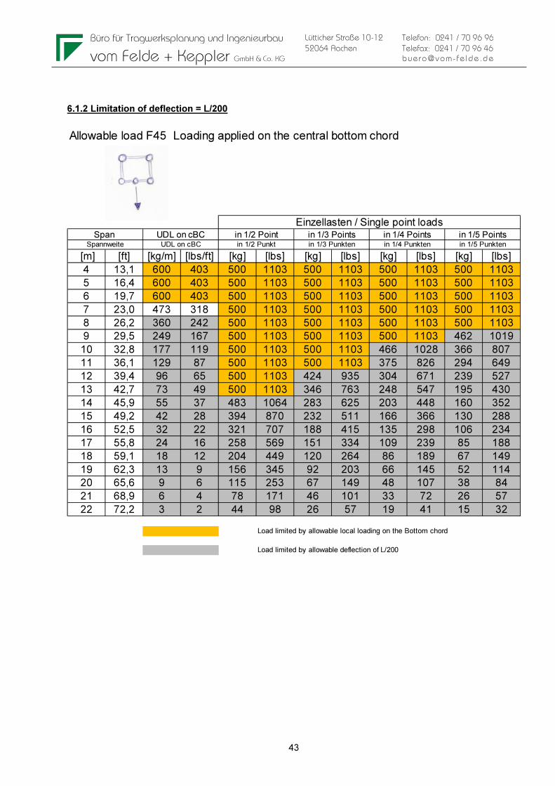
6.1.2 Limitation of deflection = L/200
Allowable load F45 Loading applied on the central bottom chord
[m] [ft] [kg/m] [lbs/ft] [kg] [lbs] [kg] [lbs] [kg] [lbs] [kg] [lbs]
4 13,1 600 403 500 1103 500 1103 500 1103 500 1103
5 16,4 600 403 500 1103 500 1103 500 1103 500 1103
6 19,7 600 403 500 1103 500 1103 500 1103 500 1103
7 23,0 473 318 500 1103 500 1103 500 1103 500 1103
8 26,2 360 242 500 1103 500 1103 500 1103 500 1103
9 29,5 249 167 500 1103 500 1103 500 1103 462 1019
10 32,8 177 119 500 1103 500 1103 466 1028 366 807
11 36,1 129 87 500 1103 500 1103 375 826 294 649
12 39,4 96 65 500 1103 424 935 304 671 239 527
13 42,7 73 49 500 1103 346 763 248 547 195 430
14 45,9 55 37 483 1064 283 625 203 448 160 352
15 49,2 42 28 394 870 232 511 166 366 130 288
16 52,5 32 22 321 707 188 415 135 298 106 234
17 55,8 24 16 258 569 151 334 109 239 85 188
18 59,1 18 12 204 449 120 264 86 189 67 149
19 62,3 13 9 156 345 92 203 66 145 52 114
20 65,6 9 6 115 253 67 149 48 107 38 84
21 68,9 6 4 78 171 46 101 33 72 26 57
22 72,2 3 2 44 98 26 57 19 41 15 32
Load limited by allowable local loading on the Bottom chord
Load limited by allowable deflection of L/200
Einzellasten / Single point loadsSpan UDL on cBC
UDL on cBC in 1/5 Punkten
in 1/5 Pointsin 1/4 Punkten
in 1/4 Pointsin 1/3 Punkten
in 1/3 Pointsin 1/2 Punkt
in 1/2 PointSpannweite

Büro für Tragwerksplanung und Ingenieurbau
vom Felde + Keppler GmbH & Co. KG
44
Lütticher Straße 10-12
52064 Aachen
Telefon: 0241 / 70 96 96
Telefax: 0241 / 70 96 46
buero@vom- fe lde.de
6.1.3 Limitation of deflection = L/300
Allowable load F45 Loading applied on the central bottom chord
[m] [ft] [kg/m] [lbs/ft] [kg] [lbs] [kg] [lbs] [kg] [lbs] [kg] [lbs]
4 13,1 600 403 500 1103 500 1103 500 1103 500 1103
5 16,4 600 403 500 1103 500 1103 500 1103 500 1103
6 19,7 578 388 500 1103 500 1103 500 1103 500 1103
7 23,0 358 241 500 1103 500 1103 500 1103 500 1103
8 26,2 235 158 500 1103 500 1103 495 1092 389 857
9 29,5 161 108 500 1103 500 1103 381 840 299 659
10 32,8 113 76 500 1103 415 916 298 657 234 516
11 36,1 81 55 500 1103 328 724 235 519 185 408
12 39,4 59 40 444 980 261 575 187 413 147 324
13 42,7 43 29 353 778 207 457 149 328 117 257
14 45,9 32 21 279 614 163 360 117 259 92 203
15 49,2 23 16 217 478 127 280 91 201 72 158
16 52,5 16 11 164 362 96 213 69 153 54 120
17 55,8 11 8 119 263 70 155 50 111 39 87
18 59,1 7 5 80 177 47 104 34 75 27 59
19 62,3 4 3 46 101 27 59 19 42 15 33
20 65,6 1 1 15 33 9 19 6 14 5 11
Load limited by allowable local loading on the Bottom chord
Load limited by allowable deflection of L/300
Einzellasten / Single point loadsSpan UDL on cBC
UDL on cBC in 1/5 Punkten
in 1/5 Pointsin 1/4 Punkten
in 1/4 Pointsin 1/3 Punkten
in 1/3 Pointsin 1/2 Punkt
in 1/2 PointSpannweite

Büro für Tragwerksplanung und Ingenieurbau
vom Felde + Keppler GmbH & Co. KG
45
Lütticher Straße 10-12
52064 Aachen
Telefon: 0241 / 70 96 96
Telefax: 0241 / 70 96 46
buero@vom- fe lde.de
6.2 Allowable loadings at side chord (LC2):
The values of the following tables are only valid for single-span girder. The truss-elements have to be braced with diagonals. Loads have to be applied acc. chapter 1.4. Loads at the middle of the couplers are not allowed. The specified values include partial safety coefficients on the loadings side acc. EN 1990 of yF = 1.50 for payloads and yG = 1.35 for selfweight of the truss. For applications which can be calculated on the basis of other codes, the partial safety factors can be adjusted (for example temporary structures acc. EN 13814, yF = 1.35 for payloads). To use the resulting allowable loads with British Standard (BS) and ANSI, allowable loads listed in tables have to be multiplied by 0.85. 6.2.1 Limitation of deflection = L/100
Allowable load F45 Loading applied on the side chords
[m] [ft] [kg/m] [lbs/ft] [kg] [lbs] [kg] [lbs] [kg] [lbs] [kg] [lbs]
4 13,1 953 640 2209 4870 1358 2994 1042 2298 859 1895
5 16,4 760 511 1879 4143 1193 2631 931 2053 778 1716
6 19,7 631 424 1629 3593 1057 2330 837 1845 684 1507
7 23,0 473 318 1434 3161 945 2084 757 1670 601 1324
8 26,2 365 245 1276 2814 853 1880 689 1519 534 1178
9 29,5 289 194 1146 2527 774 1707 614 1354 480 1057
10 32,8 234 157 1037 2287 707 1559 553 1218 434 957
11 36,1 192 129 944 2082 649 1431 501 1104 395 871
12 39,4 160 108 864 1904 598 1318 456 1006 361 797
13 42,7 135 91 793 1749 552 1218 418 921 332 732
14 45,9 115 77 731 1612 512 1129 384 846 306 675
15 49,2 99 66 675 1489 476 1049 354 780 283 624
16 52,5 79 53 625 1379 443 976 327 720 261 575
17 55,8 63 43 580 1279 395 871 283 625 223 491
18 59,1 51 34 539 1188 337 743 242 533 190 419
19 62,3 41 28 489 1078 287 633 206 454 162 356
20 65,6 33 22 415 915 243 537 175 385 137 302
21 68,9 27 18 350 771 205 453 147 325 116 255
22 72,2 21 14 292 644 171 378 123 271 97 213
23 75,5 17 11 241 531 141 312 101 223 80 176
24 78,7 13 9 194 429 114 252 82 181 64 142
Load limited by allowable deflection of L/100
Einzellasten / Single point loads
Spannweite
Span in 1/5 Punkten
in 1/5 Pointsin 1/4 Punkten
in 1/4 Pointsin 1/3 Punkten
in 1/3 Pointsin 1/2 Punkt
in 1/2 PointUDL on cBC
UDL on cBC

Büro für Tragwerksplanung und Ingenieurbau
vom Felde + Keppler GmbH & Co. KG
46
Lütticher Straße 10-12
52064 Aachen
Telefon: 0241 / 70 96 96
Telefax: 0241 / 70 96 46
buero@vom- fe lde.de
6.2.2 Limitation of deflection = L/200
Allowable load F45 Loading applied on the side chords
[m] [ft] [kg/m] [lbs/ft] [kg] [lbs] [kg] [lbs] [kg] [lbs] [kg] [lbs]
4 13,1 953 640 2209 4870 1358 2994 1042 2298 859 1895
5 16,4 760 511 1879 4143 1193 2631 931 2053 778 1716
6 19,7 631 424 1629 3593 1057 2330 837 1845 684 1507
7 23,0 473 318 1434 3161 945 2084 757 1670 601 1324
8 26,2 360 242 1276 2814 853 1880 689 1519 534 1178
9 29,5 249 167 1146 2527 774 1707 589 1298 462 1019
10 32,8 177 119 1037 2287 650 1433 466 1028 366 807
11 36,1 129 87 890 1962 522 1152 375 826 294 649
12 39,4 96 65 722 1593 424 935 304 671 239 527
13 42,7 73 49 590 1300 346 763 248 547 195 430
14 45,9 55 37 483 1064 283 625 203 448 160 352
15 49,2 42 28 394 870 232 511 166 366 130 288
16 52,5 32 22 321 707 188 415 135 298 106 234
17 55,8 24 16 258 569 151 334 109 239 85 188
18 59,1 18 12 204 449 120 264 86 189 67 149
19 62,3 13 9 156 345 92 203 66 145 52 114
20 65,6 9 6 115 253 67 149 48 107 38 84
21 68,9 6 4 78 171 46 101 33 72 26 57
22 72,2 3 2 44 98 26 57 19 41 15 32
Einzellasten / Single point loads
Spannweite
Span in 1/5 Punkten
in 1/5 Pointsin 1/4 Punkten
in 1/4 Pointsin 1/3 Punkten
in 1/3 Pointsin 1/2 Punkt
in 1/2 PointUDL on cBC
UDL on cBC

Büro für Tragwerksplanung und Ingenieurbau
vom Felde + Keppler GmbH & Co. KG
47
Lütticher Straße 10-12
52064 Aachen
Telefon: 0241 / 70 96 96
Telefax: 0241 / 70 96 46
buero@vom- fe lde.de
6.2.3 Limitation of deflection = L/300
Allowable load F45 Loading applied on the side chords
[m] [ft] [kg/m] [lbs/ft] [kg] [lbs] [kg] [lbs] [kg] [lbs] [kg] [lbs]
4 13,1 953 640 2209 4870 1358 2994 1042 2298 859 1895
5 16,4 760 511 1879 4143 1193 2631 931 2053 778 1716
6 19,7 578 388 1629 3593 1057 2330 837 1845 684 1507
7 23,0 358 241 1434 3161 920 2029 660 1456 518 1143
8 26,2 235 158 1176 2593 690 1522 495 1092 389 857
9 29,5 161 108 904 1994 531 1170 381 840 299 659
10 32,8 113 76 707 1560 415 916 298 657 234 516
11 36,1 81 55 559 1233 328 724 235 519 185 408
12 39,4 59 40 444 980 261 575 187 413 147 324
13 42,7 43 29 353 778 207 457 149 328 117 257
14 45,9 32 21 279 614 163 360 117 259 92 203
15 49,2 23 16 217 478 127 280 91 201 72 158
16 52,5 16 11 164 362 96 213 69 153 54 120
17 55,8 11 8 119 263 70 155 50 111 39 87
18 59,1 7 5 80 177 47 104 34 75 27 59
19 62,3 4 3 46 101 27 59 19 42 15 33
20 65,6 1 1 15 33 9 19 6 14 5 11
Load limited by allowable deflection of L/300
Einzellasten / Single point loads
Spannweite
Span in 1/5 Punkten
in 1/5 Pointsin 1/4 Punkten
in 1/4 Pointsin 1/3 Punkten
in 1/3 Pointsin 1/2 Punkt
in 1/2 PointUDL on cBC
UDL on cBC

Büro für Tragwerksplanung und Ingenieurbau
vom Felde + Keppler GmbH & Co. KG
48
Lütticher Straße 10-12
52064 Aachen
Telefon: 0241 / 70 96 96
Telefax: 0241 / 70 96 46
buero@vom- fe lde.de
6.3 Deflections at max. allowable loadings on center bottom chords (LC1):
6.3.1 Limitation of deflection = L/100
Deflections [cm] for F45 at max. allowable loading on central Bottom chordVorhandene Durchbiegung [cm] F45 unter max. zul. Lasten
[m] [ft] [cm] [inch] [cm] [inch] [cm] [inch] [cm] [inch] [cm] [inch]
4 13,1 0,41 0,16 0,14 0,06 0,24 0,09 0,33 0,13 0,41 0,16
5 16,4 1,00 0,39 0,28 0,11 0,47 0,18 0,64 0,25 0,81 0,32
6 19,7 2,07 0,82 0,50 0,20 0,82 0,32 1,12 0,44 1,41 0,56
7 23,0 3,05 1,20 0,81 0,32 1,31 0,52 1,79 0,70 2,25 0,89
8 26,2 4,05 1,60 1,22 0,48 1,98 0,78 2,69 1,06 3,38 1,33
9 29,5 5,19 2,05 1,77 0,70 2,84 1,12 3,86 1,52 4,66 1,83
10 32,8 6,47 2,55 2,47 0,97 3,94 1,55 5,33 2,10 5,85 2,30
11 36,1 7,89 3,11 3,34 1,31 5,29 2,08 7,15 2,82 7,19 2,83
12 39,4 9,44 3,72 4,40 1,73 6,93 2,73 8,60 3,39 8,67 3,41
13 42,7 11,14 4,38 5,68 2,24 8,90 3,50 10,18 4,01 10,29 4,05
14 45,9 12,97 5,11 7,20 2,83 11,22 4,42 11,90 4,68 12,07 4,75
15 49,2 14,95 5,89 8,98 3,54 13,35 5,25 13,76 5,42 13,98 5,51
16 52,5 16,00 6,30 11,06 4,35 15,40 6,06 15,77 6,21 16,00 6,30
17 55,8 17,00 6,69 13,46 5,30 17,00 6,69 17,00 6,69 17,00 6,69
18 59,1 18,00 7,09 16,20 6,38 18,00 7,09 18,00 7,09 18,00 7,09
19 62,3 19,00 7,48 19,00 6,38 19,00 7,48 19,00 7,48 19,00 7,48
20 65,6 20,00 7,87 20,00 6,38 20,00 7,87 20,00 7,87 20,00 7,87
21 68,9 21,00 8,27 21,00 6,38 21,00 8,27 21,00 8,27 21,00 8,27
22 72,2 22,00 8,66 22,00 6,38 22,00 8,66 22,00 8,66 22,00 8,66
23 75,5 23,00 9,06 23,00 6,38 23,00 9,06 23,00 9,06 23,00 9,06
24 78,7 24,00 9,45 24,00 6,38 24,00 9,45 24,00 9,45 24,00 9,45
UDLSpan
Einzellasten / Single point loads
in 1/5 Pointsin 1/4 Pointsin 1/3 Pointsin 1/2 Point
6.3.2 Limitation of deflection = L/200
Deflections [cm] for F45 at max. allowable loading on central Bottom chordVorhandene Durchbiegung [cm] F45 unter max. zul. Lasten
[m] [ft] [cm] [inch] [cm] [inch] [cm] [inch] [cm] [inch] [cm] [inch]
4 13,1 0,41 0,16 0,14 0,06 0,24 0,09 0,33 0,13 0,41 0,16
5 16,4 1,00 0,39 0,28 0,11 0,47 0,18 0,64 0,25 0,81 0,32
6 19,7 2,07 0,82 0,50 0,20 0,82 0,32 1,12 0,44 1,41 0,56
7 23,0 3,05 1,20 0,81 0,32 1,31 0,52 1,79 0,70 2,25 0,89
8 26,2 4,00 1,57 1,22 0,48 1,98 0,78 2,69 1,06 3,38 1,33
9 29,5 4,50 1,77 1,77 0,70 2,84 1,12 3,86 1,52 4,50 1,77
10 32,8 5,00 1,97 2,47 0,97 3,94 1,55 5,00 1,97 5,00 1,97
11 36,1 5,50 2,17 3,34 1,31 5,29 2,08 5,50 2,17 5,50 2,17
12 39,4 6,00 2,36 4,40 1,73 6,00 2,36 6,00 2,36 6,00 2,36
13 42,7 6,50 2,56 5,68 2,24 6,50 2,56 6,50 2,56 6,50 2,56
14 45,9 7,00 2,76 7,00 2,76 7,00 2,76 7,00 2,76 7,00 2,76
15 49,2 7,50 2,95 7,50 2,95 7,50 2,95 7,50 2,95 7,50 2,95
16 52,5 8,00 3,15 8,00 3,15 8,00 3,15 8,00 3,15 8,00 3,15
17 55,8 8,50 3,35 8,50 3,35 8,50 3,35 8,50 3,35 8,50 3,35
18 59,1 9,00 3,54 9,00 3,54 9,00 3,54 9,00 3,54 9,00 3,54
19 62,3 9,50 3,74 9,50 6,38 9,50 3,74 9,50 3,74 9,50 3,74
20 65,6 10,00 3,94 10,00 6,38 10,00 3,94 10,00 3,94 10,00 3,94
21 68,9 10,50 4,13 10,50 6,38 10,50 4,13 10,50 4,13 10,50 4,13
22 72,2 11,00 4,33 11,00 6,38 11,00 4,33 11,00 4,33 11,00 4,33
UDLSpan
Einzellasten / Single point loads
in 1/5 Pointsin 1/4 Pointsin 1/3 Pointsin 1/2 Point

Büro für Tragwerksplanung und Ingenieurbau
vom Felde + Keppler GmbH & Co. KG
49
Lütticher Straße 10-12
52064 Aachen
Telefon: 0241 / 70 96 96
Telefax: 0241 / 70 96 46
buero@vom- fe lde.de
6.3.3 Limitation of deflection = L/300
Deflections [cm] for F45 at max. allowable loading on central Bottom chordVorhandene Durchbiegung [cm] F45 unter max. zul. Lasten
[m] [ft] [cm] [inch] [cm] [inch] [cm] [inch] [cm] [inch] [cm] [inch]
4 13,1 0,41 0,16 0,14 0,06 0,24 0,09 0,33 0,13 0,41 0,16
5 16,4 1,00 0,39 0,28 0,11 0,47 0,18 0,64 0,25 0,81 0,32
6 19,7 2,00 0,79 0,50 0,20 0,82 0,32 1,12 0,44 1,41 0,56
7 23,0 2,33 0,92 0,81 0,32 1,31 0,52 1,79 0,70 2,25 0,89
8 26,2 2,67 1,05 1,22 0,48 1,98 0,78 2,67 1,05 2,67 1,05
9 29,5 3,00 1,18 1,77 0,70 2,84 1,12 3,00 1,18 3,00 1,18
10 32,8 3,33 1,31 2,47 0,97 3,33 1,31 3,33 1,31 3,33 1,31
11 36,1 3,67 1,44 3,34 1,31 3,67 1,44 3,67 1,44 3,67 1,44
12 39,4 4,00 1,57 4,00 1,57 4,00 1,57 4,00 1,57 4,00 1,57
13 42,7 4,33 1,71 4,33 1,71 4,33 1,71 4,33 1,71 4,33 1,71
14 45,9 4,67 1,84 4,67 1,84 4,67 1,84 4,67 1,84 4,67 1,84
15 49,2 5,00 1,97 5,00 1,97 5,00 1,97 5,00 1,97 5,00 1,97
16 52,5 5,33 2,10 5,33 2,10 5,33 2,10 5,33 2,10 5,33 2,10
17 55,8 5,67 2,23 5,67 2,23 5,67 2,23 5,67 2,23 5,67 2,23
18 59,1 6,00 2,36 6,00 2,36 6,00 2,36 6,00 2,36 6,00 2,36
19 62,3 6,33 2,49 6,33 6,38 6,33 2,49 6,33 2,49 6,33 2,49
20 65,6 6,67 2,62 6,67 6,38 6,67 2,62 6,67 2,62 6,67 2,62
UDLSpan
Einzellasten / Single point loads
in 1/5 Pointsin 1/4 Pointsin 1/3 Pointsin 1/2 Point
6.4 Deflections at max. allowable loadings on side chords (LC2):
6.4.1 Limitation of deflection = L/100
Deflections [cm] for F45 at max. allowable loading on the side chordsVorhandene Durchbiegung [cm] F45 unter max. zul. Lasten
UDL UDL
[m] [ft] [cm] [inch] [cm] [inch] [cm] [inch] [cm] [inch] [cm] [inch]
4 13,1 0,65 0,25 0,60 0,24 0,63 0,25 0,67 0,26 0,70 0,28
5 16,4 1,26 0,50 1,00 0,39 1,08 0,43 1,18 0,46 1,25 0,49
6 19,7 2,18 0,86 1,52 0,60 1,67 0,66 1,84 0,72 1,91 0,75
7 23,0 3,05 1,20 2,14 0,84 2,39 0,94 2,66 1,05 2,69 1,06
8 26,2 4,05 1,60 2,88 1,13 3,26 1,28 3,65 1,44 3,60 1,42
9 29,5 5,19 2,05 3,73 1,47 4,26 1,68 4,68 1,84 4,66 1,83
10 32,8 6,47 2,55 4,71 1,85 5,41 2,13 5,85 2,30 5,85 2,30
11 36,1 7,89 3,11 5,80 2,28 6,70 2,64 7,16 2,82 7,19 2,83
12 39,4 9,44 3,72 7,02 2,76 8,13 3,20 8,60 3,39 8,67 3,41
13 42,7 11,14 4,38 8,36 3,29 9,72 3,83 10,18 4,01 10,29 4,05
14 45,9 12,97 5,11 9,84 3,87 11,45 4,51 11,90 4,68 12,07 4,75
15 49,2 14,95 5,89 11,45 4,51 13,35 5,25 13,76 5,42 13,98 5,51
16 52,5 16,00 6,30 13,20 5,20 15,40 6,06 15,77 6,21 16,00 6,30
17 55,8 17,00 6,69 15,10 5,94 17,00 6,69 17,00 6,69 17,00 6,69
18 59,1 18,00 7,09 17,14 6,75 18,00 7,09 18,00 7,09 18,00 7,09
19 62,3 19,00 7,48 19,00 7,48 19,00 7,48 19,00 7,48 19,00 7,48
20 65,6 20,00 7,87 20,00 7,87 20,00 7,87 20,00 7,87 20,00 7,87
21 68,9 21,00 8,27 21,00 8,27 21,00 8,27 21,00 8,27 21,00 8,27
22 72,2 22,00 8,66 22,00 8,66 22,00 8,66 22,00 8,66 22,00 8,66
23 75,5 23,00 9,06 23,00 9,06 23,00 9,06 23,00 9,06 23,00 9,06
24 78,7 24,00 9,45 24,00 9,45 24,00 9,45 24,00 9,45 24,00 9,45
Span
Einzellasten / Single point loads
in 1/5 Pointsin 1/4 Pointsin 1/3 Pointsin 1/2 Point

Büro für Tragwerksplanung und Ingenieurbau
vom Felde + Keppler GmbH & Co. KG
50
Lütticher Straße 10-12
52064 Aachen
Telefon: 0241 / 70 96 96
Telefax: 0241 / 70 96 46
buero@vom- fe lde.de
6.4.2 Limitation of deflection = L/200
Deflections [cm] for F45 at max. allowable loading on the side chordsVorhandene Durchbiegung [cm] F45 unter max. zul. Lasten
UDL UDL
[m] [ft] [cm] [inch] [cm] [inch] [cm] [inch] [cm] [inch] [cm] [inch]
4 13,1 0,65 0,25 0,60 0,24 0,63 0,25 0,67 0,26 0,70 0,28
5 16,4 1,26 0,50 1,00 0,39 1,08 0,43 1,18 0,46 1,25 0,49
6 19,7 2,18 0,86 1,52 0,60 1,67 0,66 1,84 0,72 1,91 0,75
7 23,0 3,05 1,20 2,14 0,84 2,39 0,94 2,66 1,05 2,69 1,06
8 26,2 4,00 1,57 2,88 1,13 3,26 1,28 3,65 1,44 3,60 1,42
9 29,5 4,50 1,77 3,73 1,47 4,26 1,68 4,50 1,77 4,50 1,77
10 32,8 5,00 1,97 4,71 1,85 5,00 1,97 5,00 1,97 5,00 1,97
11 36,1 5,50 2,17 5,50 2,17 5,50 2,17 5,50 2,17 5,50 2,17
12 39,4 6,00 2,36 6,00 2,36 6,00 2,36 6,00 2,36 6,00 2,36
13 42,7 6,50 2,56 6,50 2,56 6,50 2,56 6,50 2,56 6,50 2,56
14 45,9 7,00 2,76 7,00 2,76 7,00 2,76 7,00 2,76 7,00 2,76
15 49,2 7,50 2,95 7,50 2,95 7,50 2,95 7,50 2,95 7,50 2,95
16 52,5 8,00 3,15 8,00 3,15 8,00 3,15 8,00 3,15 8,00 3,15
17 55,8 8,50 3,35 8,50 3,35 8,50 3,35 8,50 3,35 8,50 3,35
18 59,1 9,00 3,54 9,00 3,54 9,00 3,54 9,00 3,54 9,00 3,54
19 62,3 9,50 3,74 9,50 3,74 9,50 3,74 9,50 3,74 9,50 3,74
20 65,6 10,00 3,94 10,00 3,94 10,00 3,94 10,00 3,94 10,00 3,94
21 68,9 10,50 4,13 10,50 4,13 10,50 4,13 10,50 4,13 10,50 4,13
22 72,2 11,00 4,33 11,00 4,33 11,00 4,33 11,00 4,33 11,00 4,33
Span
Einzellasten / Single point loads
in 1/5 Pointsin 1/4 Pointsin 1/3 Pointsin 1/2 Point
6.4.3 Limitation of deflection = L/300
Deflections [cm] for F45 at max. allowable loading on the side chordsVorhandene Durchbiegung [cm] F45 unter max. zul. Lasten
Span UDL UDL
[m] [ft] [cm] [inch] [cm] [inch] [cm] [inch] [cm] [inch] [cm] [inch]
4 13,1 0,65 0,25 0,60 0,24 0,63 0,25 0,67 0,26 0,70 0,28
5 16,4 1,26 0,50 1,00 0,39 1,08 0,43 1,18 0,46 1,25 0,49
6 19,7 2,00 0,79 1,52 0,60 1,67 0,66 1,84 0,72 1,91 0,75
7 23,0 2,33 0,92 2,14 0,84 2,33 0,92 2,33 0,92 2,33 0,92
8 26,2 2,67 1,05 2,67 1,05 2,67 1,05 2,67 1,05 2,67 1,05
9 29,5 3,00 1,18 3,00 1,18 3,00 1,18 3,00 1,18 3,00 1,18
10 32,8 3,33 1,31 3,33 1,31 3,33 1,31 3,33 1,31 3,33 1,31
11 36,1 3,67 1,44 3,67 1,44 3,67 1,44 3,67 1,44 3,67 1,44
12 39,4 4,00 1,57 4,00 1,57 4,00 1,57 4,00 1,57 4,00 1,57
13 42,7 4,33 1,71 4,33 1,71 4,33 1,71 4,33 1,71 4,33 1,71
14 45,9 4,67 1,84 4,67 1,84 4,67 1,84 4,67 1,84 4,67 1,84
15 49,2 5,00 1,97 5,00 1,97 5,00 1,97 5,00 1,97 5,00 1,97
16 52,5 5,33 2,10 5,33 2,10 5,33 2,10 5,33 2,10 5,33 2,10
17 55,8 5,67 2,23 5,67 2,23 5,67 2,23 5,67 2,23 5,67 2,23
18 59,1 6,00 2,36 6,00 2,36 6,00 2,36 6,00 2,36 6,00 2,36
19 62,3 6,33 2,49 6,33 2,49 6,33 2,49 6,33 2,49 6,33 2,49
20 65,6 6,67 2,62 6,67 2,62 6,67 2,62 6,67 2,62 6,67 2,62
Einzellasten / Single point loads
in 1/5 Pointsin 1/4 Pointsin 1/3 Pointsin 1/2 Point