broadband and high speed networksfac.ksu.edu.sa/sites/default/files/switching_4.pdf · atm switch...
TRANSCRIPT
BROADBAND AND HIGH SPEED
NETWORKS
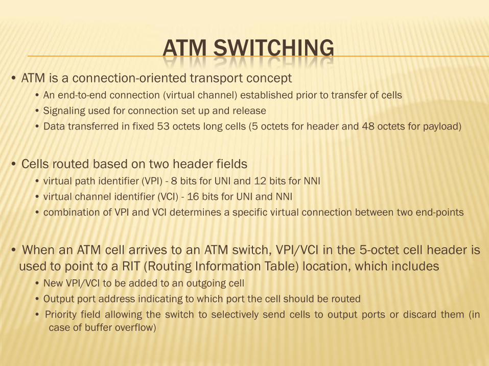
ATM SWITCHING • ATM is a connection-oriented transport concept
• An end-to-end connection (virtual channel) established prior to transfer of cells
• Signaling used for connection set up and release
• Data transferred in fixed 53 octets long cells (5 octets for header and 48 octets for payload)
• Cells routed based on two header fields
• virtual path identifier (VPI) - 8 bits for UNI and 12 bits for NNI
• virtual channel identifier (VCI) - 16 bits for UNI and NNI
• combination of VPI and VCI determines a specific virtual connection between two end-points
• When an ATM cell arrives to an ATM switch, VPI/VCI in the 5-octet cell header is
used to point to a RIT (Routing Information Table) location, which includes
• New VPI/VCI to be added to an outgoing cell
• Output port address indicating to which port the cell should be routed
• Priority field allowing the switch to selectively send cells to output ports or discard them (in
case of buffer overflow)
• Three routing modes:
• Unicast • multicast • broadcast
• In multi-cast/broadcast case, a cell is replicated into multiple copies and
each copy is routed to its intended output port/outbound VC
• ATM connections are either
• Pre-established - Permanent Virtual Connections (PVCs)
• Dynamically set up - Switched Virtual Connections (SVCs)
• Signaling (UNI or NNI) messages carry call set up requests to ATM switches
• Each ATM switch includes a call processor, which
• processes call requests and decides whether the requested connection can be established
• updates Routing Information Table based on established and released call connections
Ensuring that VPIs/VCIs of cells, which are coming from several inputs and directed to a common
output are different
• finds an appropriate routing path between source and destination ports
ATM SWITCH CHARACTERISTICS
High-Speed Interface (50Mbps to 2.4 Gbps)
Transports various types of traffic, each with different requirements Cell loss
Errors
Delay and Delay jitter
Relays (routes and buffers) cells from input to output ports
Provide control and management functions
Supports a set of traffic control requirements
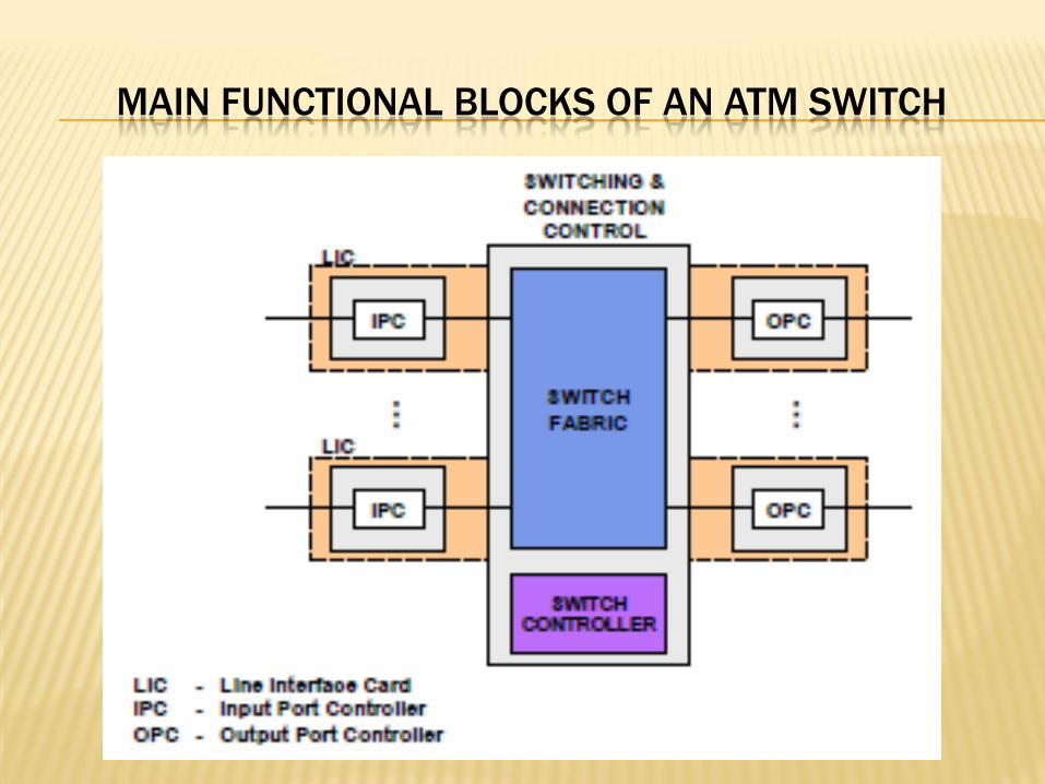
MAIN FUNCTIONAL BLOCKS OF AN ATM SWITCH
FUNCTIONAL BLOCKS OF AN ATM SWITCH
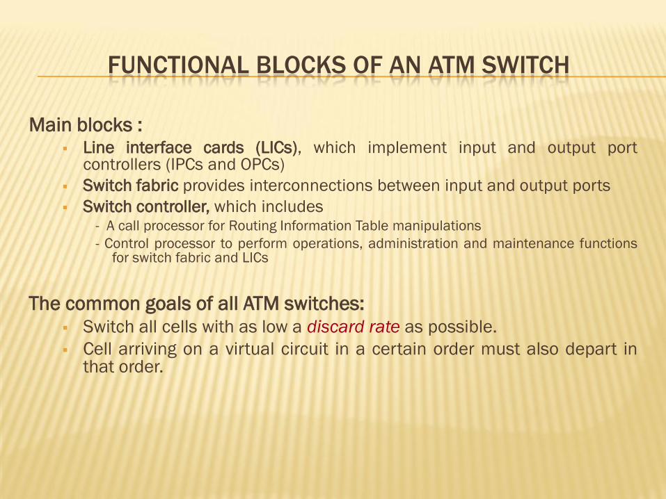
Main blocks : Line interface cards (LICs), which implement input and output port
controllers (IPCs and OPCs)
Switch fabric provides interconnections between input and output ports
Switch controller, which includes - A call processor for Routing Information Table manipulations
- Control processor to perform operations, administration and maintenance functions for switch fabric and LICs
The common goals of all ATM switches:
Switch all cells with as low a discard rate as possible.
Cell arriving on a virtual circuit in a certain order must also depart in that order.
7
ATM SWITCH
A problem occurs when the cells arriving at two or more input lines want to go to the same output port in the same cycle.
One solution is to provide a queue for each input line. If two or more cells conflict, one of them is chosen for delivery, and the rest are held for the next cycle.
The choice can be made at random, or cyclically, but should not exhibit systematic bias.
FUNCTIONS OF INPUT PORT CONTROLLER
Line termination and reception of incoming line signal
Extraction of cell header for processing
Storing of cell payload (or whole cells) to buffer memory
Head Error Control (HEC) processing
=> discard corrupted cells
=> forward headers of uncorrupted cells to routing process
• Generation of a new cell header and routing tag to be used inside switch fabric
• Cell stream is slotted and a cell is forwarded through switch fabric in a time-slot
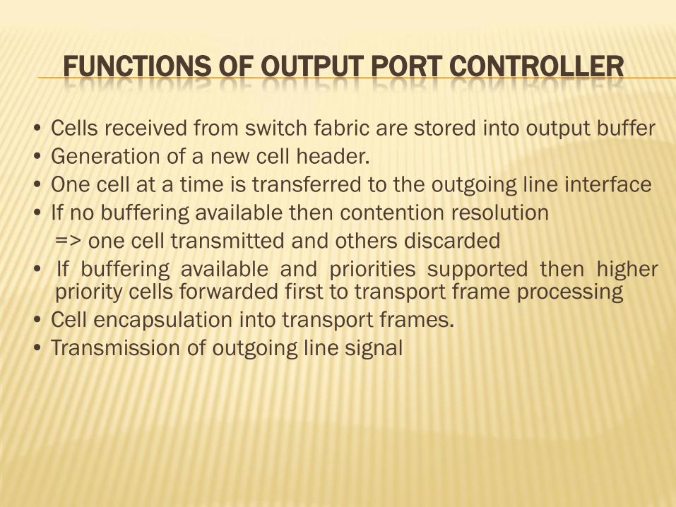
FUNCTIONS OF OUTPUT PORT CONTROLLER
• Cells received from switch fabric are stored into output buffer
• Generation of a new cell header.
• One cell at a time is transferred to the outgoing line interface
• If no buffering available then contention resolution
=> one cell transmitted and others discarded
• If buffering available and priorities supported then higher priority cells forwarded first to transport frame processing
• Cell encapsulation into transport frames.
• Transmission of outgoing line signal
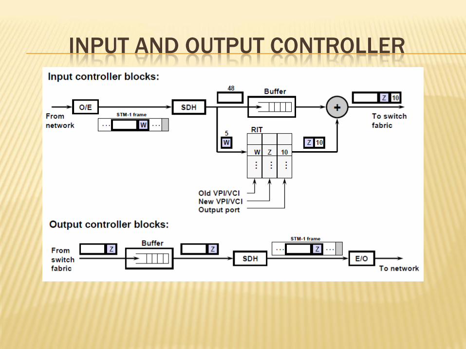
INPUT AND OUTPUT CONTROLLER
SWITCH CONTROL
• Switch controller implements functions of ATM management
and control layer
• Control plan
• Responsible for establishment and release of connections
• Signaling/management used to update routing tables in different
switches
• Processes Operations Administration Management cells
ATM SWITCHING AND BUFFERING
• Due to asynchronous nature of ATM traffic, buffering is an
important part of an ATM switch fabric design
• A number of different buffering strategies have been developed
• input buffering
• output buffering
• input-output buffering
• internal buffering
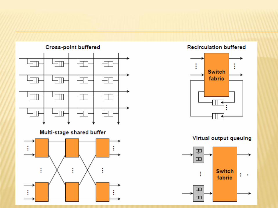
• shared buffering
• cross-point buffering
• recirculation buffering
• multi-stage shared buffering
• virtual output queuing buffering
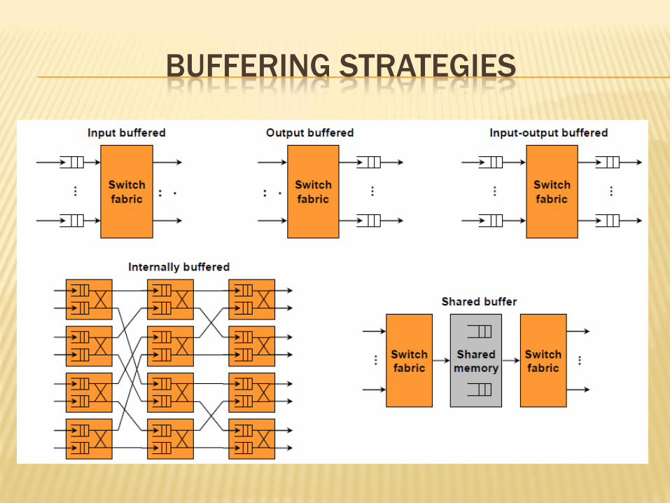
BUFFERING STRATEGIES
15
ATM SWITCH
The problem with input queuing is that when a cell has to held up in the case of the output blocking, it blocks the progress of any cells behind it. This is called head-of-line blocking.
The other solution that does not exhibit head-of-Line blocking is to have a queue for each output line.
When two cells want to go to the same output line in the same cycle, both are passed through the switch. One of them is put on the output line, and the other is queued on the output line.
16
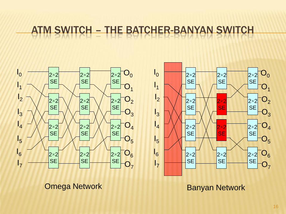
ATM SWITCH – THE BATCHER-BANYAN SWITCH
2×2
SE
2×2
SE
2×2
SE
2×2
SE
2×2
SE
2×2
SE
2×2
SE
2×2
SE
2×2
SE
2×2
SE
2×2
SE
2×2
SE
I0
I1
I4
I2
I3
I5
I6
I7
O0
O1
O4
O2
O3
O5
O6
O7
Omega Network
2×2
SE
2×2
SE
2×2
SE
2×2
SE
2×2
SE
2×2
SE
2×2
SE
2×2
SE
2×2
SE
2×2
SE
2×2
SE
2×2
SE
I0
I1
I4
I2
I3
I5
I6
I7
O0
O1
O4
O2
O3
O5
O6
O7
Banyan Network
17
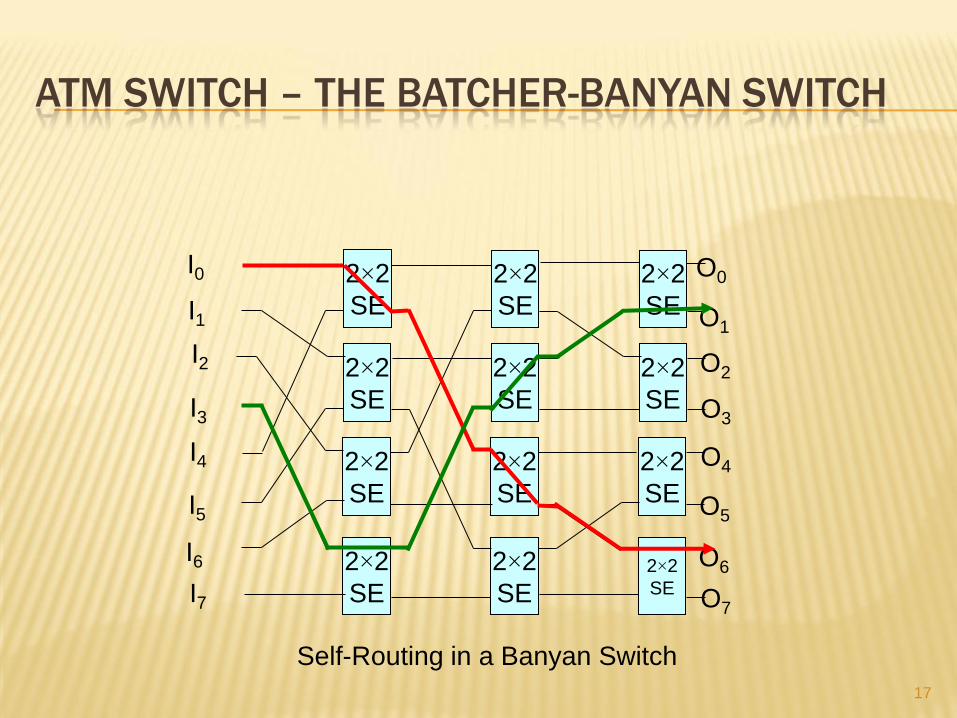
ATM SWITCH – THE BATCHER-BANYAN SWITCH
Self-Routing in a Banyan Switch
2×2
SE
2×2
SE
2×2
SE
2×2
SE
2×2
SE
2×2
SE
2×2
SE
2×2
SE
2×2
SE
2×2
SE
2×2
SE
2×2
SE
I0
I1
I4
I2
I3
I5
I6
I7
O0
O1
O4
O2
O3
O5
O6
O7
18
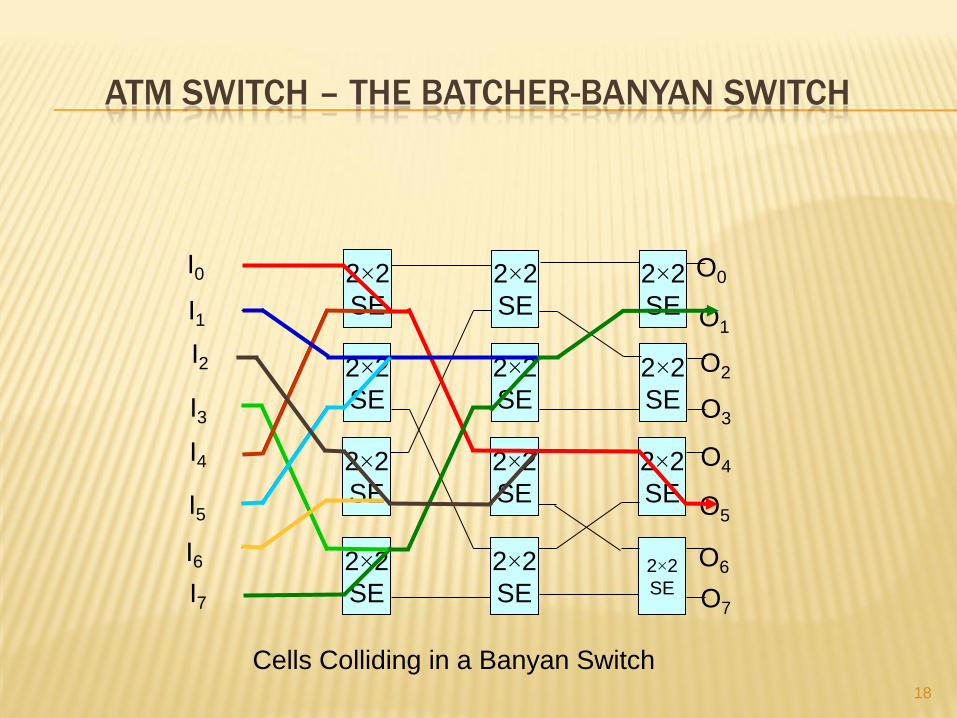
ATM SWITCH – THE BATCHER-BANYAN SWITCH
Cells Colliding in a Banyan Switch
2×2
SE
2×2
SE
2×2
SE
2×2
SE
2×2
SE
2×2
SE
2×2
SE
2×2
SE
2×2
SE
2×2
SE
2×2
SE
2×2
SE
I0
I1
I4
I2
I3
I5
I6
I7
O0
O1
O4
O2
O3
O5
O6
O7
19
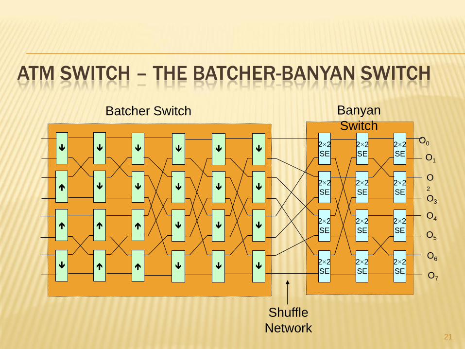
ATM SWITCH – THE BATCHER-BANYAN SWITCH
The idea behind the Batcher-Banyan switch is to put a Batcher switch in front of the Banyan switch to permute the cell into configuration that the banyan switch can handle without loss.
A Batcher switch is synchronous and works with discrete cycles.
A Batcher switch is built up of 2×2 switching elements.
When a switching element receives two cells, it compare their output addresses numerically and routes the higher one on the port in the direction of the arrow, and the lower one the other way.
20
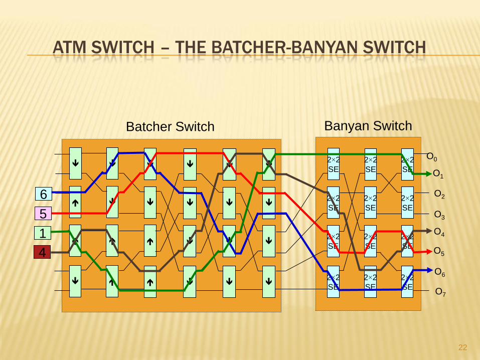
ATM SWITCH – THE BATCHER-BANYAN SWITCH
When k cells are present on the input lines, the Batcher
switch puts the cells in sort order an the first k output
lines.
After exiting the Batcher switch, the cells pass through a
shuffle connection and are then injected into a Banyan
switch.
The final result is that every cells appears on the correct
output line at the end of the Banyan switch.
21
ATM SWITCH – THE BATCHER-BANYAN SWITCH
O3
O2
O4
2×2
SE
2×2
SE
2×2
SE
2×2
SE
2×2
SE
2×2
SE
2×2
SE
2×2
SE
2×2
SE
2×2
SE
2×2
SE
2×2
SE
O0
O1
O5
O6
O7
Banyan
Switch
Batcher Switch
Shuffle
Network
22
ATM SWITCH – THE BATCHER-BANYAN SWITCH
O3
O2
O4
2×2
SE
2×2
SE
2×2
SE
2×2
SE
2×2
SE
2×2
SE
2×2
SE
2×2
SE
2×2
SE
2×2
SE
2×2
SE
2×2
SE
O0
O1
O5
O6
O7
Banyan Switch
Batcher Switch
6
5
1
4
23
HIGH PERFORMANCE SWITCHES
High performance switching is necessary to
match the high speed networks.
We can classify the switches by:
Multiplexing techniques
Packet versus circuit switching
Synchronization techniques
Internal blocking/output blocking versus non-blocking
Unicast versus multicast
Single-stage versus multistage switching
24
Multiplexing Techniques:
Time Division Multiplexing (TDM)
Wavelength Division Multiplexing (WDM)
Code Division Multiplexing (CDM)
Space Division Multiplexing (SDM)
25
Packet versus Circuit Switching:
In circuit switching, a dedicated line is set up
before transmission and is occupied by the user
who made that call until the service is terminated.
The delay and throughput are constant.
In packet switching, there is no dedicated line, and
messages are divided into packets which may be
sent on different paths; reassembling is needed in
the destination. The delay and throughput varies.
26
Packet versus Circuit Switching:
In high-speed networks, only packet switching is
considered because of the following reasons:
Packet switching can dynamically use the resources
but circuit switching has constant delay and
throughput.
Packet switching is more suitable for integrated
voice, video, and data services. Each packet is
treated the same way whether it is voice, video, or
data packets.
27
Synchronization Techniques:
There are two types of synchronization:
Synchronous Switching: To send a message according to a certain time schedule.
Asynchronous Switching: To send a message at any desired time.
Since the asynchronous switching is more flexible and can use the network resources dynamically. Therefore, high-speed networks usually use asynchronous switching.
28
Blocking versus Non-Blocking:
Switches may be categorized according to whether the packet are blocked while switched:
Blocking: Blocking may be due to either internal blocking or output blocking.
Internal Blocking: Packets (cells) collide within a switch when more than one cell tries to use the same internal link, even though they are destined for different output at the same cycle.
Output Blocking: More than one cell is destined for the same output at the same cycle.
Non_Blocking: Neither internal/output blocking has occurred.
29
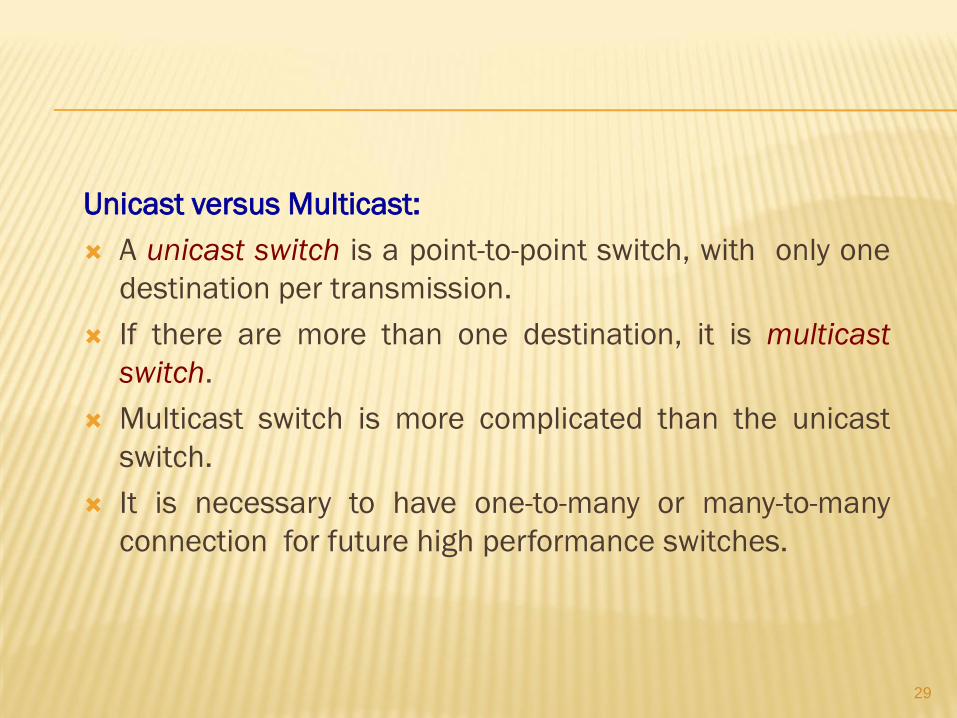
Unicast versus Multicast:
A unicast switch is a point-to-point switch, with only one
destination per transmission.
If there are more than one destination, it is multicast
switch.
Multicast switch is more complicated than the unicast
switch.
It is necessary to have one-to-many or many-to-many
connection for future high performance switches.
30
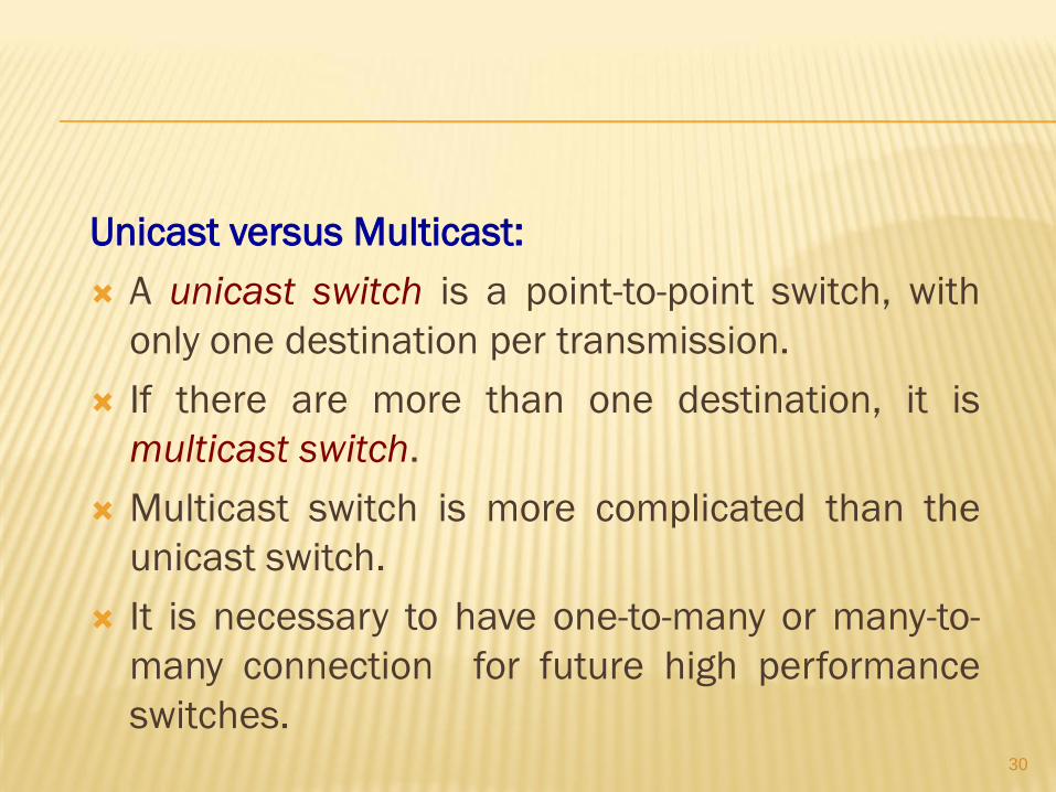
Unicast versus Multicast:
A unicast switch is a point-to-point switch, with
only one destination per transmission.
If there are more than one destination, it is
multicast switch.
Multicast switch is more complicated than the
unicast switch.
It is necessary to have one-to-many or many-to-
many connection for future high performance
switches.
31
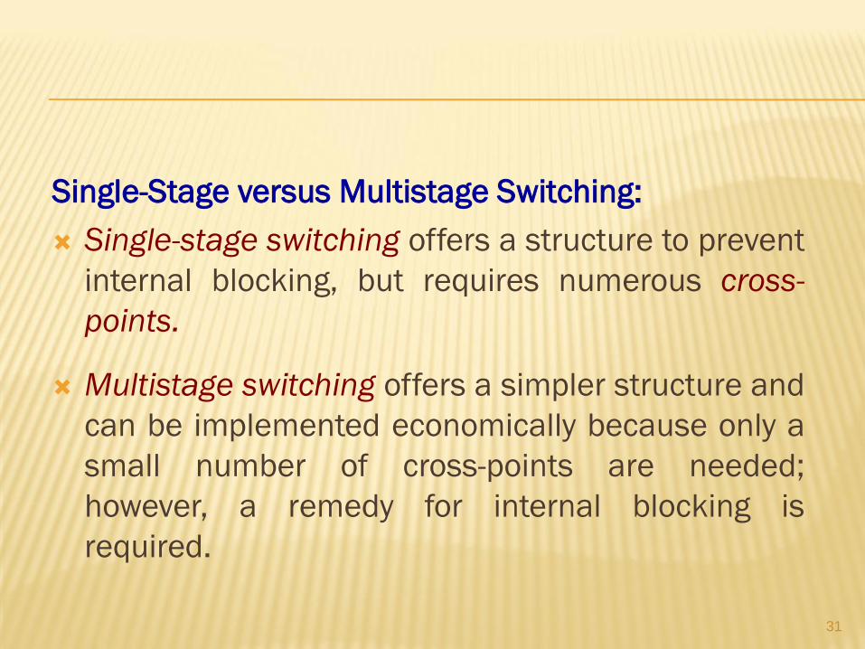
Single-Stage versus Multistage Switching:
Single-stage switching offers a structure to prevent
internal blocking, but requires numerous cross-
points.
Multistage switching offers a simpler structure and
can be implemented economically because only a
small number of cross-points are needed;
however, a remedy for internal blocking is
required.
32
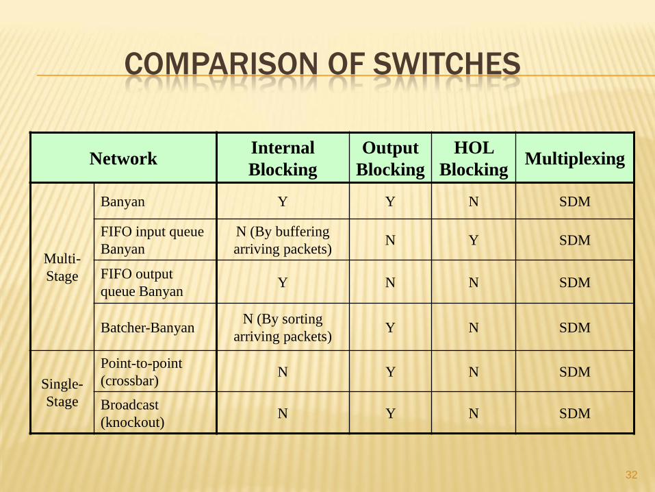
COMPARISON OF SWITCHES
Multiplexing HOL
Blocking
Output
Blocking
Internal
Blocking Network
SDM N Y Y Banyan
Multi-
Stage
SDM Y N N (By buffering
arriving packets)
FIFO input queue
Banyan
SDM N N Y FIFO output
queue Banyan
SDM N Y N (By sorting
arriving packets) Batcher-Banyan
SDM N Y N Point-to-point
(crossbar) Single-
Stage SDM N Y N
Broadcast
(knockout)