broadband applications & construction manual · · 2016-12-08dry stranded loose tube cables...
TRANSCRIPT

Broadband Applications & Construction Manual
Fiber Optic Cable Products


Table of Contents 0.1 Fiber Optic Cable Applications and Construction Manual
Table of Contents
Section 1 ................. Introduction
Section 2 ................ CommScope Fiber Optic Cable Types
Section 3 ................ CommScope Fiber Features
Section 4 ................ Storage and Testing of Fiber Optic Cable
Section 5 ................ Installation Safety Issues
Section 6 ................. Installation Basics of Fiber Optic Cable
Section 7 ................ Self-Supporting Aerial Installation of Fiber Optic Cable
Section 8 ................ Underground Installation of Fiber Optic Cable
Section 9 ................ ConQuest® Cable-in-Conduit Installation
Section 10 ............. Fiber Splicing
Section 11 ............. Emergency Restoration
Section 12 ............. Midsheath Entry
Section 13 ............. Plant Maintenance
Section 14 .............. Appendix

1.1 Introduction Fiber Optic Cables for the Broadband Cable Plant
CommScope Fiber Optic Cables for BroadbandNo matter who you are, no matter what you do at your company, you want one thing more thananything else - a cable plant that is reliable, durable and economical to install, operate and maintain.
CommScope’s fiber optic cables can do all of this, delivering maximum performance for a reasonable installed cost. CommScope’s experience with coaxial cable and broadband service providers has enabled us to design a family of fiber optic cables that is unmatched for performance, installability and reliability.
In the following chapters, we will show how CommScope fiber optic cables are the perfect solution for your network and they are no more difficult to install than traditional cable. We will prove that:
for the system buyer, CommScope fiber cables offer the absolute best signal performance at a surprisingly affordable cost –
for the engineer, CommScope fiber cable’s combination of optical performance and mechanical stamina is the best possible choice for both systemwide and partial upgrades while providing the optimal path to a fully digital network –
for the plant manager, CommScope fiber cables offer time-tested designs that perform for as long - or longer - than any competitive cable –
for the system designer, CommScope fiber cables offer benefits such as tighter mode field diameter tolerance for splice compatibility to matched clad singlemode regardless of brand, so they fit into new or existing construction –
for the craftsman, CommScope fiber optic cables offer innovations like smaller diameter cables that are easier to pull, strong ripcords to ease fiber access, ‘dry’ moisture barriers that make fiber cables easier to terminate and other features that speed installation.
CommScope fiber optic cables fit anywhere in the cable plant to ease your migration path to the digital network. If you are performing a full system upgrade, or just augmenting an existing network, you’ll discover that CommScope’s fiber optic cables are the obvious choice.
CommScopefiber cables offer
innovation thattranslates into
a superiorcabling system

Introduction 1.2 Design Details and Advantages
Features and Benefits of CommScope Fiber Optic Cables
Like their coaxial counterparts, fiber optic cables are expected to withstand the rigors of life in their application. CommScope cables are designed to meet that challenge.
Broadband fiber optic cables can be grouped into three categories:
Outside Plant Cables - These cables are designed specifically for outdoor applications, includingaerial, underground and direct burial. They feature polyethylene jackets and may also be armored.CommScope outside plant cables meet or exceed the Telcordia GR-20-CORE Mechanical and Environmental requirements, as well as ANSI/ICEA 640 requirements.
Indoor/Outdoor Cables - These cables offer a unique blend of abilities. They are tough enough to withstand the rigors of the outside plant environment, yet are riser-rated (NEC 770 OFNR) or plenum-rated (NEC 770 OFNP) for indoor use. The advantage of an indoor/outdoor cable is that it can pass from the outside to the inside intact, with no need to transition from one cable type to another, thus saving the time and labor involved in creating an additional splice point. CommScope cables meet or exceed the Telcordia GR-20-CORE Mechanical and Environmental requirements, as well as GR-20-CORE requirements for crush resistance, impact resistance, flexing and twist/bend.
Premise Cables - These cables are designed to handle the stresses of indoor applications. They include distribution and cordage cable constructions available with a riser or plenum-rated jacket (meeting the critical NEC/CEC riser [OFNR] or plenum [OFNP] safety standards).
Dry Stranded Loose Tube Cables – Available with up to 288 fibersCommScope’s Dry water blocking technology used in stranded loose tube cables provides both ease of handling and smaller overall cable diameters. By eliminating the use of gel in the core and buffer tubes, CommScope is able to provide a product that enables you to have an improved work environment that is cleaner and greener. You can decrease the amount of time it takes to prep the cable while also decreasing the amount of consumable materials required. These materials include the potentially hazardous solvents that can be bad for you and the environment. The lightweight cable design offers a smaller overall cable diameter and smaller buffer tubes which improves ease of handling, maximizes the reel capacity and the available space inside the enclosure.
1.3 Introduction Quality Control and Testing
Precise Production Control andRigorous Testing Ensure a Trouble-Free CableThe superior performance of CommScope fiber optic cables derives as much from the manufacturing process as from the components. CommScope manufactures its cables in an ISO 9001:2008 registered facility with leading edge SPC and PLC equipment. Because we have been involved with broadband cable systems since 1966, we offer a combination of extra features:
Controlled Cable Traverse - CommScope fiber optic cables are traversed so they coil neatly and permit the smoothest possible payoff, thus avoiding cable kinking and snagging during payoff in the field.
Water Penetration Testing - Both ends of the cable are cut off and tested to Telcordia and ICEA standards for water penetration. The one-meter sections are connected to a one-meter column of water. The cable section should be able to prevent seepage over its length for a 24-hour period.
Certified Test Report - A report of attenuation and length test results is attached to the reel for proof of performance and to provide a baseline for installer testing in the field.
In addition to the paper copy of the test reports, we also offer WebTrak®, a web program that puts factory cabling results on-line for all of our fiber optic cables. The WebTrak® program resides on our commscope.com website for quick access from any computer. For access to the electronic test reports, all the installers need is the 11-digit serial number printed on the cable jacket and a footage or meter marker for reference. Installers can then enter this number and pull up the cable’s factory test results from anywhere in the world at any time of the day or night.
CommScope also takes the extra step of spooling cable onto high quality reels. A good, nonwarped reel helps payout and lessens the chance of the cable rubbing against the reel to cause abrasion of the cable jacket. A solid reel also prevents painful splinters - something the experienced installer will appreciate.

CommScope Drop CablesThe Efficient Design for Broadband Networks
The design of Drop cables complements the needs often found in the broadband cable plant. Drop cables offer a compact, flexible and cost-efficient configuration that provides low-loss performance when twelve fibers or less are needed.
Drop cables feature the tightest loaded and unloaded bend radii in the industry for optimum flexibility in installation. These cables meet virtually all Telcordia GR-20-CORE requirements*. The drop cables were designed to meet the S-110-717-2002 “Standard for Optical Fiber Drop Cable”.
The Flat Drop cable design is a small, lightweight cable construction designed for ease of handling and installation. The costs associated with bonding and grounding is eliminated with the all-dielectric design while the Toneable design incorporates a 24 AWG copper conductor that is used to locate the cable after it is buried in the field. Dual ripcords simplify cable access and installation. Both designs are qualified to the ANSI/ICEA S-110-717-2002 Standard for Optical Fiber Drop Cable and are both RUS/RDUP: RD Telecommunications Program listed.
Versions include:
Outside plant armored up to 12 fibersOutside plant dielectric up to 12 fibersFlat Drop up to 12 fibersToneable Flat Drop up to 12 fibers
Drop cables are commonly used to branch from the main cable route to outlying distribution points.
All drop cables can be pre-installed in conduit.
*GR-20-CORE requirements call for tensile strength of 600 lbs. Drop cables are rated at 300lbs., which is more than sufficient because of their smaller size, lighter weight and excellent flexibility.
Cable Types 2.1 Drop Cables

CommScope Central Tube -An Efficient Alternate to Stranded Loose Tube
System providers striving to reduce costs and increase network efficiency can choose CommScope’scentral tube design for CommScope fiber optic cable.
Central Tube Cables feature a single buffer tube to accommodate higher fiber counts. Central tube cables save time and money because the single tube design reduces termination cost. Their smaller diameter makes them pull easier and take up less valuable conduit space.
Color-coded high-strength binders are applied in a counter-rotating fashion to separate fibers into easily-traced bundles of 12. The central tube is gel-filled for moisture protection.
Outside plant versions meet or exceed the Telcordia GR-20-CORE Mechanical and Environmental requirements. Riser-rated indoor/outdoor versions meet or exceed the Telcordia GR-409-CORE, GR-20-CORE and ANSI/ICEA 696 Mechanical and Environmental requirements.
Available versions include:
Outside plant armored up to 48 fibersOutside plant dielectric up to 48 fibers
All central tube cables can be pre-installed in conduit.
2.2 Cable Types Central Tube Cables

CommScope Stranded Loose Tube - Traditional Cables with Innovative Design
In situations requiring high fiber counts, stranded loose tube cables offer the capacity and design flexibility required for high-traffic trunk applications as well as excellent fiber management.
Stranded Loose Tube Cables offer excellent flexibility and the durability for long distance pulls. Certain stranded loose tube cables can be ordered in lengths as long as 7.5 miles (12.2 km). Where more arduous conditions prevail (temperature extremes, higher incident of rodent damage), CommScope offers stranded loose tube cables with especially rugged combinations of jackets and armor.
Outside plant versions meet or exceed all Telcordia GR-20-CORE, as well as ANSI/ICEA 640 requirements. Indoor/outdoor versions meet or exceed all Telcordia GR- 409-CORE, GR-20-CORE and ANSI/ICEA 696 requirements.
Available versions include:Outside plant armored and dielectric up to 576 fibers
Outside plant self-supporting armored andnon-armored Figure-8 up to 288 fibers
Outside plant rugged condition (double jacket/single armor)up to 288 fibers
Outside plant rugged condition (triple jacket/double armor)up to 288 fibers
Indoor/outdoor riser-rated dielectric up to 288 fibersIndoor/outdoor plenum-rated dielectric up to 144 fibers
Loose tube cables are best used for high-traffic trunk and distribution.
All loose tube cables can be pre-installed in conduit.
Cable Types 2.3 Stranded Loose Tube Cables

2.4 Cable Types ADSS Cables
CommScope’s ADSS Cables -Special Purpose Stranded Loose Tube Cables
ADSS (All-Dielectric Self-Supporting) is a loose tube non-metallic fiber optic cable that is designed to be installed without the assistance of metal strand. An ADSS cable uses aramid yarn and a high tensile central strength member for support. ADSS cable attaches directly to the pole or tower with the use of special attachment hardware (see page 2.5).
Special Note
ADSS fiber optic cables are custom designed to fit the maximum span lengths of your plant. Be sure to have this information available for your customer service representative when placing orders.

Advantages of ADSS Cable
• ADSS cable offers great strength and flexibility for placement on overhead transmission towers or poles eliminating the need for a support messenger.
• Tension strength capability required for installation in the toughest environmental and electrical conditions and completely unaffected by electromagnetic fields.
• Single strand or ribbon technologies for ease of mid-span breakout or high fiber count needs.
• ADSS cable offers high tensile strength and can reach spans in excess of two kilometers (6,500 feet). Making a perfect aerial solution for river or gorge crossings.
• ADSS cable reduces the cost of installation with less manpower and the elimination of metal strand and lashing.
ADSS Hardware
• ADSS pole hardware (shown at right) is made available through Tyco and Preformed Line Products.
Construction Methods
• Please reference 7.1 through 7.4 of this manual for installation instructions.
• CommScope recommends verification of sag and tension for self-supporting cables. Please call our Technical Resource Center for recommendations.
Cable Types 2.5 ADSS Cables

2.6 Cable Types Hybrids
CommScope Hybrid Cables
Revenue generating units, or RGUs are central to the business model of every broadband service provider and more than any other cable construction, hybrid cable designs are becoming the choice to enable numerous outlets for cable television, HDTV, computer networking, multi-line telephone service, security, energy management systems, and more–all via a single cable run.
Using our unique position as the one cable supplier manufacturing coax, twisted pair and fiber optic cables under one roof, CommScope employs advanced engineering technologies by extruding and testing each component of a hybrid cable congruently.
CommScope offers true hybrid/composite cables featuring subunits contained within a single jacket. Our constructions offer the additional protection of an outside jacket compared to designs offered by many vendors that are merely a bundle of subunits wrapped together with a special tape or binder thread – frequently called “speed pull”. CommScope hybrid cables are constructed from subunits carefully selected and performance-verified individually and as the sum of individual parts.
Special designs can be produced quickly and economically at your request, using our flexible manufacturing system. In fact, CommScope will help define the product that best meets your specific needs. Contact any CommScope sales representative at (800) 982-1708.
(Shown at left, left to right)Fiber + UTP + Coax Hybrid CableFiber + UTP Hybrid CableFiber + Coax Hybrid Cable

Cable Types 2.7 Hybrids
CommScope Hybrid Cables Features and Benefits
Features
May contain copperUTP, coax and fiber optic subunits individually jacketed then cabled in a single bundle under one smooth surface.
Coax cable subunits
Singlemode and/or multimode fiber optic cable subunits
Copper twisted pair subunits
Benefits
• Great for multiple cable drops, phone/data lines, security systems and multimedia requirements
• Saves time and installation dollars
• Easier materials management
• Components can be easily separated into individually jacketed points for easy termination
• Capable of voice transmission, cable location and site powering
• Avails future proofing for the demands of advanced data video and telecommunications for subscribers
• Less prone to snags and violations of cable bend radius limits
• Enhances the cable’s ruggedness enabling each subunit to better withstand the rigors of cable installation and remote field applications
• Robust drop or trunk cable components are available in a variety of braid options to provide protection against moisture, liquids and gases while boasting excellent mechanical strength and transmission qualities
• Excellent for transmission of critical audio and video signals with extraordinary reliability and clarity. No other medium today can challenge fiber optics in bandwidth, distance and noise immunity
• Available in armored constructions for additional rodent and environmental protection
• Tight buffered, loose tube or central tube designs offered in singlemode or multimode optical fiber types and a range of grades
•Often used in broadband networks for powering nodes and pedestals
• Specify Category 5e rather than Cat 5. The cost differential is small compared with the quality and performance advantages gained– in- cluding the potential for significantly higher speeds and greater capacity

2.8 Cable Types Alternative Jacket
Alternative Jacket
CommScope’s Alternative Jacket is a patented polymer blend that utilizes food grade additives including bittering agents and capsaicinoids to deter squirrels from chewing the jacket. The material is intended to make the act of cutting their teeth back on cable an unpleasant experience. The combination of bitterness and sensation of heat from the capsaicinoids have proven to be enough to discourage squirrels from this behavior.
The additives blended into the polymer are temporarily unpleasant but are not harmful to wildlife.
CommScope’s Alternative Jacket Fiber Optic Cable is installed using the same process as standard outside plant stranded loose tube fiber optic cable.
Handling PrecautionsSome people may show sensitivity to the additives in AJ resulting in mild skin reaction. CommScope recommends the use of gloves while handling and working with Alternative Jacket cables, and thoroughly washing hands with soap and water after working with the cable. Avoid contact with eyes and take normal precautions including the use of safety glasses when preparing cable.
- Non-toxic, environmentally friendly
- Unpleasant to taste and smell
- Reduces the amount and intensity of chews
- Standard warranty applies
- Designated by 3 green tracers on the outer jacket

The Cable Industry’s Fiber SupplierTM
LightScope ZWP® singlemode fiber optic cable continues a CommScope tradition of being the leading manufacturer of innovative and performance-enhancing products for the communications industry.
CommScope’s LightScope ZWP® fiber optic cable offers Full Spectrum AdvantageTM transmission capability while being fully backwards compatible with existing singlemode legacy fiber optic cable plants. LightScope ZWP® makes available 30% more usable transmission spectrum, which can be used for return path, enhanced video services such as video on demand (VOD) or Dedicated Wavelength ServicesTM for business or other applications.
Features & Benefits• LightScope ZWP®, zero water peak full spectrum singlemode fiber optic cable, opens up transmission over the previously unusable wavelength range from 1360nm to 1460nm known as the “Extended Band” or E-band.
• Enables 16 channel coarse wavelength division multiplexing (CWDM) as a lower cost alternative to dense wavelength division multiplexing (DWDM) in unamplified portions of hybrid fiber coax (HFC) networks.
• Enables transmission from 1260nm to 1625nm adding 30% more usable spectrum.
• For the communication industry, making use of the full transmission spectrum translates to added capacity enabling service-rich systems and revenue enhancing growth.
• Fully compatible with legacy standard singlemode fiber optic networks.
• Provides future bandwidth upgradeability.
Fiber Features 3.1 LightScope ZWP®

Reduced Attenuation
LightScope ZWP cable is designed for use in the wavelengths between1260 nm and 1625 nm, including the for-merly off-limit wavelengths in the E-band. LightScope ZWP provides superior attenuation performance throughout this range of wavelengths, including a lower attenuation performance at 1383 nm than at 1310 nm.
LightScope ZWP - Reduced Water Peak
Standard singlemode fiber has a pronounced attenuation increase at 1383 nm. This region, called the water peak, is an area within the fiber’s transmis-sion spectrum where light is increasingly absorbed by the hydroxyl (OH-) ions pres-ent within the structure of the glass core. Hydroxyl ions are the cause of increased attenuation within the E-band. These ions are removed during the manufacturing of LightScope ZWP, thereby reducing attenu-ation spikes in the E-band and rendering this portion of the transmission spectrum usable. The E-band accounts for 30% of the transmission spectrum available in silica glass fibers.
LightScope ZWP provides superior low wa-ter peak performance in the E-band over the lifetime of the product. This performance is ensured by a unique ultra-purifying manufacturing process which virtually eliminates hydroxyl ions in the glass fiber. The resulting decrease in attenuation over the water peak region, and relatively lower 1400 nm band dispersion (compared with conventional fiber in the 1550 band), results in a product offering increased transmission spectrum and the economic benefits of less expensive transmission options.
3.2 Fiber Features LightScope ZWP®

Fiber Features 3.3LightScope ZWP® Specifications
LightScope ZWP Type 8W Singlemode Fiber Specifications Dispersion-Unshifted, Matched-Clad Singlemode Fiber ITU-T G.652.D, G.657.A1 Physical Characteristics
Cladding Diameter 125 ± 0.7 µm
Core/Clad Offset < 0.5 µm
Coating Diameter (uncolored) 245 ± 10 µm
Coating Diameter (colored) 254 ± 7 µm
Coating/Cladding Concentricity Error, maximum 12 µm
Clad Non-Circularity < 1%
Mechanical Characteristics
Prooftest 100 kpsi (.69 Gpa)
Coating Strip Force 0.3 - 2.0 lbf (1.3 - 8.9 N)
Fiber Curl > 4 m
Dynamic Fatigue Parameter (nd) > 18 nd
Macrobend 100 turns @ 50mm mandrel
1550 nm 0.05 dB maximum
Macrobend 1 turn @ 32mm mandrel
1550 nm 0.05 dB maximum
Environmental Characteristics
Temperature Dependence -60°C to +85°C < 0.05 dB
Temperature Humidity Cycling -10°C to 85°C up to 95% RH < 0.05 dB
Water Immersion, 23 + 2°C < 0.05 dB
Heat Aging, 85 + 2°C < 0.05 dB
*Initial attenuation at 1385 nm shall be no greater than the specified value. The attenuation shall not exceed 0.35 dB/km at this wavelength during the life of the cable.

3.4 Fiber Features CommScope Fiber Specifications - LightScope ZWP
LightScope ZWP Type 8W Singlemode Fiber Specifications Dispersion-Unshifted, Matched-Clad Singlemode Fiber ITU-T G.652.D, G.657.A1 Optical Characteristics, Wavelength Specific
Attenuation, Loose Tube Cable1310 nm 0.34 dB/km 1385 nm 0.31 dB/km1550 nm 0.22 dB/km
Attenuation, Tight Buffer Cable1310 nm 0.50 dB/km 1385 nm 0.50 dB/km1550 nm 0.50 db/km
Mode Field Diameter1310 nm 9.2 + 0.3 µm 1385 nm 9.6 + 0.6 µm1550 nm 10.4 + 0.6 µm
Group Refractive Index1310 nm 1.4671385 nm 1.4681550 nm 1.468
Dispersion1310 nm 3.5 ps/(nm-km) from 1285 to 1330 nm1550 nm 18 ps/(nm-km)
Optical Characteristics, Wavelength Specific
Attenuation @ 1385 nm 0.32 dB/kmPoint Defects 0.10 dBCutoff Wavelength < 1260Zero Dispersion Wavelength 1302 - 1322 nmZero Dispersion Slope 0.090 ps/(km-nm-nm)Polarization Mode Dispersion Link Design Value < 0.06 ps/sqrt(km)Specifications are subject to change without notice.

Fiber Features 3.5 Splice Compatibility with other Fibers/Mode Field Diameter- LightScope ZWP®
A Median Mode Field Diameter Produces a Superior Splice
Mode Field Diameter - Optical fiber is composed of two regions - a narrow core surrounded by amuch thicker cladding. In a typical fiber size specification, the diameter of the core is 8.3 µm - the cladding is 125 µm (µm is a micron or 1/1,000,000th of a meter).
In singlemode fiber, about 80% of the light is carried in the core - the remaining 20% is carried in the cladding. The core and section of the cladding that carries the light is referred to as the mode field.
Mode Field Diameter (MFD) is a critical performance specification for splicing and connectorization purposes. Matching mode field diameters minimizes the splicing or connector losses associated with joining two different sections of fiber. It also minimizes the number of attempts needed to get a connection to meet the low loss require-ments of today’s high capacity systems.
In an ideal world, all fibers would have the exact same MFD. The reality is that there will be some variance in MFD from fiber to fiber. However, minimizing this variance will save an operator both time and money. The industry standard for MFD is 9.2 µm ± 0.5 µm, with some manufacturers reducing this to ± 0.4 µm. To provide even better performance, LightScope ZWP is engineered to produce an MFD or 9.2 µm ± 0.3 µm.
fiber side view

A More-Centered Core Keeps Splices on Target
Along with mode field diameter, core/cladding offset is another factor that affects the quality of the splice.
Core/Cladding Offset - All manufacturers strive to build the core as close to the center of the cladding as possible so that when the fiber is viewed in cross-section, the core and cladding form concentric circles. If the core is in the exact center of the cladding (the optimal position), the core/cladding offset is zero. A low core/cladding offset means a cleaner splice because the cores of the fiber align more precisely.
Telcordia standards permit a core/cladding offset of no more than 1 µm. A worst-case scenario of splicing two 8.3 µm/125 µm fibers with a 1 µm offset would cause enough splice loss to force the technician to break and resplice the fiber. This wastes time and slows the speed of the installation.
LightScope ZWP fiber optic cables have a core/cladding offset of no more than 0.5 µm. The result is faster, lower-loss splicing, not only with our own cables but to those of other manufacturers for speedier installations and better system performance.
8.3/125 µm fiber withindustry standard
1.0µm max. core offset
8.3/125 µm fiber withLightScope ZWP
0.5µm max. core offset
Worst-case scenariosmaximum core/cladding offset
3.6 Fiber Features Splice Compatibility With Other Fibers/Core-Cladding Offset LightScope ZWP

Physical Characteristics
Cladding Diameter 125 ± 0.7 µm
Core/Clad Offset < 0.5 µm
Coating Diameter (uncolored) 245 ± 5 µm
Coating Diameter (colored) 256 ± 8 µm
Coating/Cladding Concentricity Error, maximum 12 µm
Clad Non-Circularity < 1%
Mechanical Characteristics
Prooftest 100 kpsi (.69 Gpa)
Coating Strip Force 0.3 - 2.0 lbf (1.3 - 8.9 N)
Fiber Curl > 4 m
Dynamic Fatigue Parameter (nd) > 20 nd
Macrobend 100 turns @ 75mm mandrel
1550 & 1625 nm 0.05 dB maximum
Macrobend 1 turn @ 32mm mandrel
1550 & 1625 nm 0.50 dB maximum
Environmental Characteristics
Temperature Dependence -60°C to +85°C < 0.05 dB
Temperature Humidity Cycling -10°C to 85°C up to 95% RH < 0.05 dB
Water Immersion, 23 + 2°C < 0.05 dB
Heat Aging, 85 + 2°C < 0.05 dB
*Initial attenuation at 1385 nm shall be no greater than the specified value. The attenuation shall not exceed 0.35 dB/km at this wavelength during the life of the cable.
LightScope NZDTM Type 8T Optical Fiber:Non-Zero Dispersion Shifted Singlemode Fiber ITU-T G.655.A,B,C
Fiber Features 3.7 CommScope Fiber Specifications LightScope NZDTM

Optical Characteristics, Wavelength Specific
Attenuation, Loose Tube Cable 1310 nm 0.45 dB/km 1550 nm 0.25 dB/km 1625 nm 0.34 dB/km Attenuation, Tight Buffer Cable 1310 nm N/A 1550 nm N/A 1625 nm N/A Mode Field Diameter 1310 nm 1550 nm 8.4 + 0.6 µm 1625 nm 8.9 + 0.6 µm Group Refractive Index 1310 nm 1.471 1550 nm 1.470 1625 nm 1.470Dispersion 1310 nm -8 ps/(nm-km) (typical) 1550 nm 2.6 to 6 ps/(nm-km) from 1530 - 1565 nm 1625 nm 4.0 to 8.9 ps/(nm-km) from 1565 - 1925 nm
Optical Characteristics, General
Attenuation @ 1385 nm 1.0 dB/kmPoint Defects 0.10 dBCutoff Wavelength < 1260Dispersion Slope < 0.05 ps/(km-nm-nm) at 1550 nmPolarization Mode Dispersion Link Design Value < 0.1 ps/sqrt(km)Specifications are subject to change without notice.
LightScope NZDTM Type 8T Optical Fiber:Non-Zero Dispersion Shifted Singlemode Fiber ITU-T G.655.A,B,C
3.8 Fiber Features CommScope Fiber Specifications - LightScope NZDTM

Fiber Features 3.9 CommScope Fiber Specifications - LightScope NZDTM
Why Dispersion-Shifted Fiber?
Dispersion-shifted fiber is needed when the bit rate and transport distance combination is such that dispersion begins to degrade system performance. This can occur when bit rates are above 2.5 Gb/s or when transport distances are over 100 km. Dispersion-shifted fiber, as the name implies, shifts the zero dispersion point from its location at 1310 nm in standard singlemode fiber (SMF) to above 1450 nm (see chart). More importantly though, by shifting the dispersion curve it also reduces the dispersion level in the 1550 nm which is the region where Dense Wavelength Division Multiplexing (DWDM) and optical amplification technology operates. Reducing the dispersion through the use of dispersion shifted fiber enables a greater reach at the same level of dispersion or improved system performance at the same reach. The alternative to dispersion-shifted fiber is dispersion compensation. Dispersion compensation is usually achieved through the use of a long section of highly negative dispersion fiber that is typically housed in a module and inserted in line with the system. While this is a viable option, it must be weighed against that additional loss, increased Polarization Mode Dispersion (PMD), and additional components and cost that dispersion compensation introduces.
LightScope NZDTM is a Non-Zero Dispersion-Shifted (NZD) fiber designed for use with systems that operate in the 1550 nm region. Some of its key performance capabilities include:
• 4x reduction in dispersion levels at 1550 nm relative to standard SMF
• Reduced dispersion slope resulting in very low dispersion in both the C and L bands
• Low dispersion coupled with a moderate effective area provides for excellent Non-Linear Distortion (NLD) performance. Non-linear products such as Four Wave Mixing (FWM) are kept at levels that are sufficiently low to avoid any significant signal degradation
• A moderate effective area results in very efficient Raman amplification. This can be used as a lower noise substitute for conventional optical amplification
Overall, LightScope NZD provides equivalent or better transmission characteristics than other NZD fibers, translating into greater reach, and a lower transmission Bit Error Rate (BER)

Inspecting and Unloading Fiber Optic Cables
Trouble-free unloading begins with letting your CommScope Customer Service Representative know of any special packaging or delivery requirements (no shipping dock available, call before delivery, etc.). CommScope will make every reasonable effort to comply with your shipping needs.
When the shipment arrives, make sure the cable types and quantities match the bill of lading. Contact your CommScope Customer Service Representative if there is a discrepancy.
Inspect every reel and pallet of material for damage as it is unloaded. Suspect cable should be set aside for a more detailed inspection before the shipping documents are signed.
Reels of fiber optic cable are shipped on their rolling edges, not stacked flat on their sides. Make sure you note the orientation and condition of the reel in your inspection.
If any cable damage is visible or suspected and if it is decided to accept the shipment, note the damage and the reel number on ALL copies of the bill of lading.
If the damage is too extensive to accept the shipment, advise the carrier’s driver that the shipment is being refused because of the damage. Immediately notify CommScope’s Customer Service Department so that arrangements can be made for a replacement shipment.
Cable performance test results taken at CommScope are provided with each reel. Compare them to your own tests using the methods outlined on page 4.4.
CommScopemakes every
effort to assurethat fiber opticcables arrive inthe same 100%ready-to-install
condition aswhen they left
the factory
4.1 Storage and Testing Inspection

Storage and Testing 4.2 Cable Handling
Unloading and Moving Fiber Optic Cable
Fiber optic cable reels are typically delivered on a substantially heavier reel than coaxial cable.Therefore, they must be loaded and unloaded using a crane, special lift truck or forklift.
Forklifts must pick the reel up with the flat side of the reel facing the driver. Extend the forks under the entire reel. DO NOT pick the reel up with the lags facing the driver. Keep all reels upright on their rolling edges and never lay them flat or stack them.
All reels are marked with an arrow indicating the direction in which the reel must be rolled. Roll only in the indicated direction.
DO NOT drop reels off the back of the truck onto a stack of tires, onto the ground or any other surface.The impact may injure personnel and will damage the cable. Always use ample personnel to safely unload shipments of cable.
The reel is labeled with handling directions. Consult these directions if you have any doubt about handling the reel.
Storing Fiber Optic CableFiber optic cable is always stored on the rolling edge and typically away from the main cable storage area to prevent possible damage. To prevent reel deterioration during long term storage, store optical fiber cable in a manner that protects the reel from the weather.
Testing CommScope Fiber Optic Cables
While testing reels of fiber optic cables at delivery is not required, testing prior to, during and afterconstruction is essential to identify any cable performance degradation caused during installation.
There are four phases in fiber optic cable testing:
1) Visual inspection for shipping damage (see page 4.1),
2) Pre-installation testing, which occurs immediately after cable delivery,
3) Installation testing, which occurs after the cable is installed or placed in the plant and at every splice point, and
4) Final acceptance testing, which occurs just prior to activation.
Pre-Installation TestingPre-installation testing typically consists of an OTDR (Optical Time Domain Reflectometer) test performed at 1550 nm. All CommScope fiber optic cables are OTDR-tested prior to shipment and the test report is attached to the reel. A pre-installation test will verify the characteristics of the cable and check for any shipping damage. The tests can be jointly conducted by the system operator and the construction group in order to preclude future difficulties should a cable be damaged during construction.
Installation TestingCable should be tested once it has been placed in the plant and prior to splicing to make sure thatthere has been no installation damage. Installation testing is usually done with an OTDR. Splice testingtakes place after each splice to insure that a clean, low-loss connection was made. OTDR, local injection detection and/or profile alignment, can be used alone or in combination for splice testing.
Post Installation - Final Acceptance TestingThe usual post installation testing method is to perform end-to-end OTDR testing. The results should be compared to the pre-installation test. It is highly recommended that an ongoing testing program be established after the system is powered up (see page 13.1).
Every reel ofCommScope fiber
optic cable is exten-sively tested for at-
tenuation, flaws and continuity and a copy
of the certification report is attached to
the reel
4.3 Storage and Testing Factory and On-Site Testing

Storage and Testing 4.4 OTDE Attenuationi Testing
Attenuation Testing With an OTDR
Attenuation testing with an OTDR (Optical Time Domain Reflectometer) should be performed as part of any pre-installation test regimen. All the fibers in a cable should be tested and the results recorded and documented.
Attenuation is defined as the loss in optical power as it travels through fiber optic cable and is usually expressed in decibels per 1,000 meters (dB/km). Attenuation testing can be used to compare actual attenuation data to the specifications provided by CommScope. Field attenuation characteristics of a reel of fiber optic cable should be the same as when it was tested at the CommScope factory. Other general attenuation tests include cable reel acceptance, splice loss verification, and final end-to-end measurements. Signature traces should be made of all fibers after splicing and connectorization to show the entire cable route. These traces will be invaluable if trouble develops in the passive cable plant.
OTDRs have several significant advantages over other test methods. OTDRs are extremely versatileinstruments that can be operated by a single technician. Through periodic comparison withthe initial signature traces, OTDRs may provide early warning of a potential catastrophicfailure by indicating points of stress in the cable.
The OTDR operates by transmitting an optical pulse through the fiber. Signal loss is measuredby charting the reflections of a pulse of light as it is backscattered by the glass structure ormore strongly reflected by a flaw or break in the fiber or the end of the cable itself. Distance to the
flaw is measured by the elapsed time between the generation of the pulse and the arrival of the reflected light back at the OTDR. The result (a linear trace of the fiber displayed as distance from the source [horizontal axis] versus relative power [vertical axis]) is displayed on a screen or printed out.
Operation of OTDRs vary according to manufacturer. Consult your OTDR documentation for instructions.
Typical OTDR display

System Documentation and Field Test Data
Documentation is essential in the optical fiber plant. While a coaxial installation deals with a single conductor over a span, an optical fiber installation involves multiple fibers in a cable that may besignificantly longer. If a cable is damaged during installation and not detected by on-going field testing, the replacement costs can be extremely high.
DocumentationThe minimum documentation required for a fiber optic cable network should include the schematicdrawings, splice loss data, end-to-end optical loss measurements and end-to-end OTDR signature traces.
The purpose of this documentation is to provide historical references for maintenance and emergency restoration. By maintaining this data, the system operator is assured of a prompt response by the quick identification, location and repair of any problem that may occur within a cable route.
Field DataTwo types of field data should be collected during the installation process. Calculated data is obtained from cable reel data sheets and splicing logs. Measured data, such as OTDR data, is obtained from end-to-end cable testing. This data becomes part of the permanent record for both the customer and CommScope. This data provides information that accurately characterizes the optical condition of the passive fiber optic cable plant.
It is essential that any operator of a fiber transmission system maintain adequate information about that system for maintenance, trouble-shooting and emergency restoration procedures. By periodically verifying the attenuation loss of the cable system, the cable operator may be able to avoid future problems.
The ability toquickly trace
and solve cableplant problemsdepends on the accuracy of the
installationdocumentation
4.5 Storage and Testing Documentation

Installation Safety Issues 5.1 Industry Organizations
Installation Safety Issues
Construction of underground facilities requires a substantial amount of manpower, tools and equipment. Underground and aerial construction will expose the manpower, tools and equipment to hazards, dependent upon field conditions and circumstances.
The Occupational Safety and Health Administration (OSHA) defines a qualified employee as “any worker who by reason of training and experience has demonstrated his ability to safely perform his duties.” Only a qualified employee should be assigned duties that could cause harm or potential harm to the construction crew, general public, cable plant and other utilities. This manual cannot identify the many hazards that exist in the construction environment, nor can it dictate the caution required with all tools, equipment and field conditions. CommScope continues this manual with the assumption that the construction personnel performing the work are qualified employees.
Three sets of national codes and standards apply to the construction of underground facilities. The OSHA Safety and Health Standards applies to work in telecommunications and utility installations. The National Electric Code (NEC) applies to building utilization wiring, i.e. inside plant construction. The NEC applies specifically, but not limited to, plant that is within or on public and private buildings or other structures. The National Electric Safety Code (NESC), generally applies to outside plant construction.
Municipal, state, county and local codes are often applied to the construction of telecommunication and utility systems or work that involves their respective properties and right-of-ways. Pole Lease Agreements often stipulate specific practices related to safety.
These codes, regulations and specified practices should be investigated, interpreted, communicated and observed.

Underground Safety
Telecommunication construction is typically done within right-of-way dedicated for the routing of other underground systems – municipal and utility pipes, wires, cables, and conduits.
Damage to any one of these utilities could cause a disruption of services. At worst, it may cause catastrophic harm to personnel and surrounding property.
It is usually required by law that you contact all operators of these systems prior to the start of any excavation, including those that are out of the right-of-way (ROW). These system operators will indicate horizontal location of their plants with a flag or paint mark, called a locate mark or locate. Law usually requires that the subsurface plant owner perform this duty within a defined time period and ensure that the locate marks are correctly positioned. The primary intent of the locate mark is to PREVENT damage to conflicting ROW, not to define liability. However, the recovery of damages resulting from excavation work is generally decided with high consideration given to the locate marks.
Once the horizontal location of the conflicting ROW has been established, the depth, or ‘vertical’ location of the ROW must be determined. This is usually done by potholing, or carefully digging a hole until the conflicting ROW (or its warning tape) is located.
The owner of the real estate should also be contacted prior to excavation. There may be a water sprinkler, closed circuit television or communication systems buried in or around the ROW. The excavating party should also make necessary locate marks on their existing plant.
Underground installations typically terminate in a pit or trench that is accessible to the public. Pits and trenches MUST be guarded by barricades, warning devices and covers.
5.2 Installation Safety Issues Underground Safety

Installation Basics 6.1 Overview
Both CommScope dielectric and armored fiber optic cables can be used in aerial installations. Dielectric cables contain no metal components, which tends to minimize lightning strikes and avoid electrical field crossover from power lines. Armored cables offer more mechanical protection from rodent attack but must be grounded. CommScope fiber optic cables come in several styles in both armored and dielectric versions:
Fiber Optic Drop a compact, flexible and cost-efficient central tube design for 1 to 12 fibers
Central Tube similar design to the drop cables with a higher capacity of up to 48 fibers
Stranded Loose Tube available in up to 576 fibers
All Dielectric a stranded loose tube, non-metallic design available with up to 288 fibers Self-Support
CommScope also offers some of these cable types in indoor/outdoor riser-rated versions (NEC 770 OFNR) and plenum-rated versions (NEC 770 OFNP) that can transition from outdoor to indoor without a need for a splice point. Regular OSP cables must transition or terminate within 50 feet of entering a building.
The two preferred methods for aerial installation are the back-pull/stationary reel method and the drive-off/moving reel method. Circumstances at the construction site and equipment/manpower availability will dictate which placement method will be used.
The back-pull/stationary reel method is the usual method of cable placement. The cable is run from the reel up to the strand, pulled by a block that only travels forward and is held aloft by cable blocks. Excess (slack) loops (see page 6.4) are then formed. Lashing takes place after the cable is pulled.
The drive-off/moving reel method may take less manpower and save time in cable placement and lash-up. In it, the cable is attached to the strand and payed-off a reel moving away from it. The cable is lashed as it is being pulled. Excess (slack) loops (see page 6.4) are made during lashing. Make sure all down guys at corners and dead ends are installed and tensioned prior to cable placement.
Aerial Installation of CommScope Fiber Optic Cable
Indoor/outdoorcables transition
from OSP tobuilding without
having to changecable types

Pulling Tension
Pulling tensions for various CommScope OSP fiber optic cables are shown in this chart. Kellems® orcrimp-on grips are used to pull the fiber optic cable. Make sure you use the correct-sized grip forthe cable being pulled. If aramid yarn is part of the cable structure, tie it to the grip to furtherdistribute the pulling force.
NEVER EXCEED the maximum pulling tension. Excessive pulling force will cause the cable to permanently elongate. Elongation may cause the optical fiber to fail by strain. Good construction techniques and proper tension monitoring equipment are essential.
Place enough cable blocks along the route to keep cable sag to a minimum. Excessive sagging willincrease pulling tension. When pulling, do not let the cable ride over the reel flange as it may scuff or tear the jacket.
Tail loading is the tension in the cable caused by the mass of the cable on the reel and reel brakes. Tail loading can
be minimized by using little to no braking during the pay-off of the cable from the reel -at times, no braking is preferred. Rotating the reel in the direction can also minimize tail loading of pay-off, but be careful not to let the reel overspin.
Dynamometers are used to measure the dynamic tension in the cable. They allow continuous review of pulling tension. Sudden increases in pulling tension, caused by factors such as a cable falling from a block or a cable binding against pole-line hardware, can be detected immediately.
Break-away swivels are used alone or in conjunction with dynamometers to ensure that the maximum pulling tension is not exceeded. A swivel with a break tension equal to that of the pulling tension of the cable is placed between the cable puller and pulling grip. Use one break-away swivel for each cable being pulled.
CommScope’sflexible
constructionmeans less
pulling effortis required
OSP Fiber Optic Max. Pulling TensionCable Type lbs/newtons
Drop/Flat Drop Dielectric 300/1335
Drop Armored 300/1335
Central Tube Self-Support 607/2700
Central Tube Dielectric 607/2700
Central Tube Armored 607/2700
Loose Tube Dielectric 607/2700
Loose Tube Armored 607/2700
6.2 Installation Basics Pulling Tension

Installation Basics 6.3 Bending Radiius
Bending Radius
Cables are often routed around corners during cable placement. A more flexible cable (one with a smaller bending radius) will require less pulling tension to get it through a bend in the route. CommScope fiber optic cables are designed for maximum flexibility to ease installation.
NEVER EXCEED the minimum bending radius. Overbent cable may deform and damage the fiber inside and can cause high attenuation.
Bending radius for fiber optic cable is given as loaded and unloaded. Loaded means that the cable is under pulling tension and is being bent simultaneously. Unloaded means that the cable is under no tension or up to a residual tension of 30% of its maximum pulling tension. The unloaded bending radius is also the radius allowed for storage purposes.
OSP Fiber Optic CableType/Max. Fiber Count Loaded Unloaded
Flat Drop/12 3.5 (9.0) 1.8 (4.5)Toneable Flat Drop/12 3.5 (9.0) 1.8 (4.5)Drop Dielectric/12 6.8 (17.4) 3.4 (8.7)Drop Armored/12 6.4 (16.2) 3.2 (8.1)Central Tube Armored/24 8.6 (22.0) 4.3 (11.0)Central Tube Armored/48 10.2 (26.0) 5.1 (13.0) Can be removed if neededCentral Tube Armored/96 11.8 (30.0) 5.9 (15.0) Can be removed if neededCentral Tube Dielectric/24 7.9 (20.2) 4.0 (10.1)Central Tube Dielectric/48 9.5 (24.2) 4.7 (12.1) Can be removed if neededCentral Tube Dielectric/96 11.1 (28.2) 5.5 (14.1) Can be removed if neededDry Loose Tube Armored/60 9.4 (23.9) 4.7 (11.95)Dry Loose Tube Armored/72 9.8 (24.9) 4.9 (12.43)Dry Loose Tube Armored/96 11.0 (28.0) 5.5 (13.99)Dry Loose Tube Armored/120 12.2 (31.1) 6.1 (15.57)Dry Loose Tube Armored/144 13.8 (35.3) 6.9 (17.64)Dry Loose Tube Armored/216 13.8 (35.3) 6.9 (17.64)Dry Loose Tube Armored/288 15.7 (40.0) 7.9 (20.02)Loose Tube Armored/432 18.1 (46.0) 9.0 (23.0)Loose Tube Armored/576 20.6 (52.4) 10.3 (26.2)Dry Loose Tube Dielectric/60 8.2 (21.0) 4.1 (10.5)Dry Loose Tube Dielectric/72 8.6 (21.8) 4.3 (10.9)Dry Loose Tube Dielectric/96 9.8 (25.0) 4.9 (12.5)Dry Loose Tube Dielectric/120 11.1 (28.2) 5.5 (14.1)Dry Loose Tube Dielectric/144 12.6 (32.2) 6.3 (16.1)Dry Loose Tube Dielectric/216 12.6 (32.2) 6.3 (16.1)Dry Loose Tube Dielectric/288 14.5 (37.0) 7.3 (18.5)Loose Tube Dielectric/432 16.9 (43.0) 8.4 (21.5)Loose Tube Dielectric/576 19.5 (49.6) 9.7 (24.8)
Min. Bending Radius in/cm
Flat Drop/12 3.5 (9.0) 1.8 (4.5) Toneable Flat Drop/12 3.5 (9.0) 1.8 (4.5) Drop Dielectric/12 6.8 (17.4) 3.4 (8.7) Drop Armored/12 6.4 (16.2) 3.2 (8.1) Central Tube Armored/24 8.6 (22.0) 4.3 (11.0) Central Tube Armored/48 10.2 (26.0 5.1 (13.0) Central Tube Dielectric/24 7.9 (20.2) 4.0 (10.1) Central Tube Dielectric/48 9.5 (24.2) 4.7 (12.1) Dry Loose Tube Armored/60 9.4 (23.9) 4.7 (11.95) Dry Loose Tube Armored/72 9.8 (24.9) 4.9 (12.43) Dry Loose Tube Armored/96 11.0 (28.0) 5.5 (13.99) Dry Loose Tube Armored/120 12.2 (31.1) 6.1 (15.57) Dry Loose Tube Armored/144 13.8 (35.3) 6.9 (17.64) Dry Loose Tube Armored/216 13.8 (35.3) 6.9 (17.64) Dry Loose Tube Armored/288 15.7 (40.0) 7.9 (20.02) Loose Tube Armored/432 18.1 (46.0) 9.0 (23.0) Loose Tube Armored/576 20.6 (52.4) 10.3 (26.2) Dry Loose Tube Dielectric/60 8.2 (21.0) 4.1 (10.5) Dry Loose Tube Dielectric/72 8.6 (21.8) 4.3 (10.9) Dry Loose Tube Dielectric/96 9.8 (25.0) 4.9 (12.5) Dry Loose Tube Dielectric/120 11.1 (28.2) 5.5 (14.1) Dry Loose Tube Dielectric/144 12.6 (32.2) 6.3 (16.1) Dry Loose Tube Dielectric/216 12.6 (32.2) 6.3 (16.1) Dry Loose Tube Dielectric/288 14.5 (37.0) 7.3 (18.5) Loose Tube Dielectric/432 16.9 (43.0) 8.4 (21.5) Loose Tube Dielectric/576 19.5 (49.6) 9.7 (24.8)

Back-Pull/Stationary Reel - Puller Set-Up and Block Placement
Cable Block/Corner Block PlacementUse a cable block lifter/lay-up stick to place cable blocks on the strand every 30 - 50 feet (9 - 15 meters).
Place corner blocks at all corners greater than 30° in the pole line. NEVER PULL CABLE OVER THEEND ROLLERS OF CORNER BLOCKS. Use the entire set or they will deform the cable. At corners less than 30°, cable blocks can be placed on the strand several feet from and on each side of the pole/line hardware. The cable blocks should allow the cable to move through the corner without undue bending or drag.
Cable Puller Set-Up is Cable > Grip > Breakaway Swivel > PullerAttach an appropriate cable grip to each cable. Secure the grip to the cable with tape to keep thecable from backing out of the grip should the pulling tension be relaxed.
Place a breakaway swivel between the pulling grip and the cable puller. An in-line dynamometer maybe placed there along with the breakaway swivel.
Place the cable puller on the strand and close the puller gates to secure the puller to the strand.
Attach a pulling line to the cable puller. Pull the cable puller along the strand by hand or by winch. Place cable blocks to support the cable as it is pulled. The cable puller has an internal brake, which prevents the cable puller from moving backward on the strand when the pulling tension is released.
Do not overspin the reel. Keep the cable wraps tight.
Remember toplace slack
loops duringthe pull
totaling 5%of the lengthof the cable
6.31 Aerial Installation Back-Pull/Stationary Reel Passing the Pole

Back-Pull/Stationary Reel - Passing the Pole and Power Winching
Passing the Cable Puller at PolesPull the cable puller to the pole and release the tension in the pulling line. Pass the cable and the puller across the pole face and the pole/line hardware, and attach the cable puller back to the strand. Place cable blocks on each side of the pole.
At corner block locations, pass the cable puller to the opposite side of the pole and route the cablesthrough the corner block.
Power Winching MethodsPower winching a pull line to install fiber optic cable is a method often used when the poleline is obstructed or is in extremely rough terrain because the pull line can be placed without tension concerns. In winching, the pull line is placed in the cable puller and run along the strand. Cable blocks must be placed at this time. Once the pull line is run, it is attached to the fiber optic cable.
Carefully tension the pull line and begin pulling. Adjust the reel brakes to prevent undue pulling tension. Real-time tension monitoring is required as is radio communication between the lineman observing the pull-out and the winch operator. Intermediate cable handling may be required as the pulling grips approach cable and corner blocks.
CommScope’slong lengths
and flexibilitylend itself to
power winching
Aerial Installation 6.32 Back-Pull/Stationary Reel Block Placement

Back-Pull/Stationary Reel - Lashing
Excess Cable for Splicing and Future RelocationLeave enough excess cable at the first and last pole of the pull to facilitate splicing. The cable should be able to reach the ground, enter a splicing trailer/truck and be placed in an enclosure. If you are unsure of the length, the rule of thumb is to always leave more, not less. Cap the open cable end to prevent contamination from dirt or moisture. Coil the cable, being careful not to exceed the minimum bend radius, and tie the loop to the strand away from the pole.
Excess cable should be pulled out and lashed back to the strand to facilitate splicing or the future relocation of the pole-line. Normally, an additional 5% of the total cable span is stored during the installation.
Attach the Lashing Wire ClampPlace the lasher on the strand. Wrap the lashing wire twice around the strand in the same direction as the twist in the strand and in the lay of the strand. Pass the lashing wire between the washers of the lashing wire clamp without overlapping the wire. Wrap the wire around the clamp to the post on the opposite side of the clamp and wrap it twice around the post. Cut the wire and tuck it between the halves of the lashing wire clamp. Use appropriate-sized spacers to prevent fiber optic cable from rubbing against the pole hardware. NOTE: Use double lashing with two or more cables, at street and railroad crossings.
Place the cable within the lasher. A cable positioner may be arranged ahead of the lasher for extra guidance as the lasher is pulled toward the reel.
Keep Sag to a Minimum - Use Cable Blocks for as Long as PossibleFor safety purposes, keep sag on the cable at a minimum until it enters the lasher. Do not let thecable sag so low that it can be hit or run over by traffic. Leave the cable blocks in place until thelasher is close enough to support the cable. As the lasher approaches cable blocks, either removethem with a cable block lifter or push the cable blocks to the next pole by utilizing a cable blockpusher.
6.33 Aerial Installation Back-Pull/Stationary Reel Lashing

Back-Pull/Stationary Reel - Passing the Lasher at the Pole
Passing the Lasher at the PolePull the lasher toward the pole to be passed. Attach a lashing wire clamp to the strand as shown onAerial Installation (page 6.15). Remove the lasher from the strand and move it across the pole-face to thestrand and cable on the opposite side of the pole.
Put the cable into the lasher. Close the gates to prevent the lasher from being pulled backward along the strand. Cut the lashing wire from the lasher and secure the lashing wire to the lashing wire clamp. Make sure that the lashing wire does not loosen from around the cable.
Attach appropriate straps and spacers as needed. At the back end of the lasher, attach a lashing wireclamp to the strand about to be lashed. Attach the lashing wire to the clamp. Continue lashing as before.
Carefully rotate the cable reel to take up any excess cable slack prior to lashing each section.
Do not lash the cable too tightly. Although fiber optic cables expand far less than coaxial cables, they must be permitted to contract and expand along the strand or the cable may buckle and fail. Remember also to leave a small loop for strain relief.
Lashing Fiber and Coaxial Cables TogetherFiber optic cables that are lashed in the same cable bundle as coaxial cables can be routed directlyalong the strand when a coaxial expansion loop is encountered. A simple 2 - 4 inch (5 -10 cm) loop willprovide sufficient strain relief.
Aerial Installation 6.34 Back-Pull/Stationary Reel Passing the Lasher

Installation - Drive-Off/Moving Reel Set-Up and Lashing
In the drive-off/moving reel method, the cable is attached to the strand and payed-off by moving the reel away from it. The cable is lashed as it is being pulled. Excess (slack) loops are made during lashing.
Trailer Set-Up • Attach the Lasher, Set-Up Chute and CablePay the cable off the top of the reel rotating toward the rear of the cable trailer. Use minimal reel braking. Attach a lashing wire clamp to the strand (see page 6.15) 3 - 5 feet (1 to 1.5 meters) from the pole. Place the lasher on the strand and attach the lashing wire to the lashing wire clamp (page 6.15).
Position the set-up chute in front of the lasher and attach it to the lasher with a block pusher (or shotgun). Attach the pull line to the set-up chute or lasher. Thread the cable through the set-up chute and place the cable in the lasher.
Leave enough excess cable at the first and last pole of the pull to reach the ground, enter a splicing trailer/truck, be spliced and be placed in an enclosure. If in doubt about the length, leave more rather than less. Cap the open cable end to prevent contamination from dirt or moisture. Coil the cable, being careful not to exceed the minimum bend radius, and tie the loop to the strand away from the pole.
The cable should move only through the chute. If the pole-line is offset from the reel, observe the cable closely as it moves through the chute. Cable reel offset may cause the cable to abrade on the reel flange and the cable in the chute to bind.
Remember toplace slack
loops duringthe pull
totaling 5%of the lengthof the cable
6.35 Aerial Installation Driive-Off/Moving Reel Set-up

Installation - Drive-Off/Moving Reel - Passing the Pole
Allow a Loop to Relieve Cable StrainStop the lasher about 3 feet (1 meter) from the pole. Allow for a 2 - 4 inch (5 - 10 cm) loop at the pole hardware for strain relief.
Passing the PoleAttach a lashing wire clamp to the strand. Disconnect the set-up chute and lasher and pass them across the pole-face. Place them on the unlashed strand far enough from the pole to accommodate a small strain relief loop. Reassemble the set-up chute and lasher.
Close the lasher gates. Cut the lashing wire and secure it to the lashing wire clamp. Make sure that thelashing wire does not loosen from around the cable.
Attach another lashing wire clamp to the strand on the unlashed side of the pole allowing enoughdistance for a strain relief or equipment. Connect the wire from the lasher to the new clamp. Place the cable in the set-up chute and the lasher.
Rotate the cable reel to take up any excess slack. Continue until the installation is complete.
Aerial Installation 6.36 Drive-Off/Moving Reel - Passing the Pole

Installation - Overlashing Existing Cable
Overlash Cable PlacementOverlashing cables onto existing cable plant is similar to installing cable onto new strand. However,there are some unique aspects:
Do not tight-lash fiber and coaxial cables.
A sag and tension analysis should be performed to see if the new cable load will overwhelm the strand.
Use special overlash cable puller blocks and continuously maintain and monitor the pulling line tension. Overlash cable pullers do not have a strand brake and will be pulled backward on the span by the tension in the cables being pulled.
Use cable blocks designed specifically for overlash applications. Place them onto the cable bundle with a cable block lifter and lift the cable with a cable lifter. During lashing, remove the cable blocks from the cable bundle with a cable block lifter. DO NOT PUSH THE CABLE BLOCKS in front of the lasher as that may damage existing cables.
Remove all straps and spacers from the existing cable bundle during lash-up. New straps and spacersmay be required - check the old ones carefully to see if they need replacing.
SPANMASTER® SoftwareCommScope offers SpanMaster, software that aids in the calculation of span sag and tension.SpanMaster is Windows® compatible and is available through your CommScope sales representative or may be downloaded from our website, www.commscope.com.
CommScope’sSpanmaster®
software helpsyou quickly
calculate sagand tension
of spans
6.37 Aerial Installation Overlashing

Vertical Clearance of Wires, Conductors and Cables Above Ground, Roadway, Rail or Water Surfaces
Insulated communication conductors and cables, messengers, surge protection wires, grounded guys,
underground guys exposed to 0 to 300 neutralconductors meeting rule 230E1,
supply cables meeting rule 230C1
Nature of surface underneath wire,conductors or cables
1. Track rails of railroads (except electrified railroads using overhead trolley conductors)
2. Roads, streets and other areas subject to truck traffic
3. Driveways, parking lots and alleys
4. Other land transversed by vehicles, such as cultivated, grazing, forest, orchard, etc.
5. Spaces and ways subject to pedestrians or restricted traffic only
6. Water areas not suitable for sailboating or where sailboating is prohibited
7. Water areas suitable for sailboating, including lakes, ponds, reservoirs, tidal waters, rivers, streams and canals with an unobstructed surface area of:
a. Less than 20 acres b. Over 20 to 200 acres c. Over 200 to 2000 acres d. Over 2000 acres
8. Public or private land water areas posted for rigging or launching sailboats
Feet Meters
23.5 7.2
15.5 4.7
15.5 4.7
15.5 4.7
9.5 2.9
14.0 4.0
17.5 5.3 25.5 7.8 31.5 9.6 37.5 11.4
Clearance above ground shall be 5 feet greater than in 7 above, for the type of water areas served by the launching site.
Aerial Installation 6.38 Vertical Clearances of Above Ground Cables

Self-Supporting Cable Installation - Drive-Off/Moving Reel
The drive-off method is the simplest way to place self-supporting central tube cable.
Attach the cable to pole-line hardware at the first pole of the cable run. Leave enough excess cable tofacilitate splicing. The cable should be able to reach the ground, enter a splicing trailer/truck and beplaced in an enclosure. If in doubt about the length, leave more rather than less. Cap the open cable end to prevent contamination from dirt or moisture. Coil the cable being careful not to exceed the minimum bend radius and tie the loop to the top of the pole.
Ground and bond the armor at the first pole. The armor is contacted by means of a clamp (sometimescalled ‘shark jaws’) that pierces the jacket to reach the armor.
Cable blocks should be installed at all poles not framed in dead-end hardware configurations.Pay the cable off the top of the reel and manually place it into the cable block. Continue to pay-offthe cable slowly and uniformly to keep the pulling tension even. Stop-and-go pulling may cause thecable to ‘bounce’ and damage it at the pole blocks. Do not let the cable reel overspin and let slackcable spin off the reel. (Brakes will be required.)
Lift the cable from the cable blocks and place it into the suspension clamp once the cable route hasbeen tensioned as required. Tension the cable wherever there are dead end hardware configurations.Ground and bond the armor at these locations once the cable is tensioned.
7.1 Self-Supporting Cable Installation Drive Off/Moving Reel
Self-Supporting Cable Installation - Back-Pull/Stationary Reel Set-Up
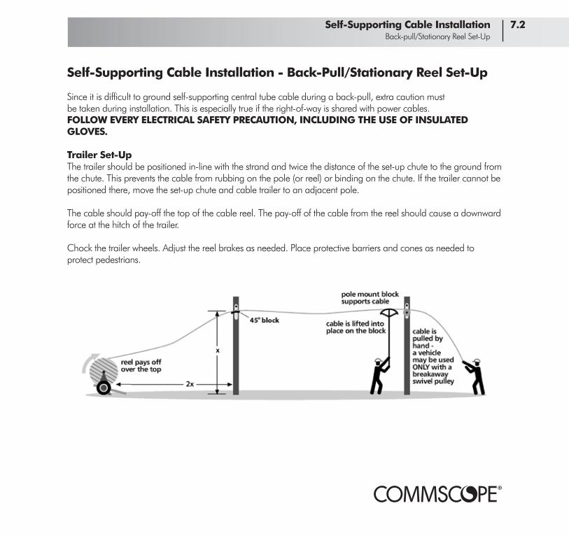
Since it is difficult to ground self-supporting central tube cable during a back-pull, extra caution mustbe taken during installation. This is especially true if the right-of-way is shared with power cables.FOLLOW EVERY ELECTRICAL SAFETY PRECAUTION, INCLUDING THE USE OF INSULATEDGLOVES.
Trailer Set-UpThe trailer should be positioned in-line with the strand and twice the distance of the set-up chute to the ground from the chute. This prevents the cable from rubbing on the pole (or reel) or binding on the chute. If the trailer cannot be positioned there, move the set-up chute and cable trailer to an adjacent pole.
The cable should pay-off the top of the cable reel. The pay-off of the cable from the reel should cause a downward force at the hitch of the trailer.
Chock the trailer wheels. Adjust the reel brakes as needed. Place protective barriers and cones as needed to protect pedestrians.
Self-Supporting Cable Installation 7.2 Back-pull/Stationary Reel Set-Up

Self-Supporting Cable Installation - Back-Pull/Stationary Reel
Pulling Set-UpAttach the correct-sized cable grip. Then attach a swivel and a pulling line to the grip. Attention should be given to the tension that is being placed on the cable. There is not a practical method to monitor the tension in the cable itself.
Cable Block PlacementUse cable blocks designed to be attached directly to the pole hardware. Pull the cable out along the pole line and lift it into the cable blocks with a cable lifter or by hand from a bucket truck.
DF Cable
Attach the drop wire clampDF (flat) cable can be attached to a P, Q, etc... hook using a drop wire clamp normally specified for telephone wire. Models include:Senior Industries #SI-0972SBThomas & Betts #23-88881 MacLean Power Systems #2PRMS
These designs use a shim to trap the cable in the clamp’s shell, and then use a wedge to tighten the shim. The weight of the cable produces tension that tightens the wedge in the shell to secure the cable.
7.3 Self-Supporting Cable Installation Back-Pull/Stationary Reel Pulling

Underground Installation of CommScope Fiber Optic Cable
CommScope fiber optic cables for direct burial are always armored, while those intended to run in duct or conduit may be either armored or dielectric constructions. CommScope offers several types of fiber optic cable designed specifically for underground installation:
Drop a compact, flexible and cost-efficient central tube design for 1 to 12 fibers - its small diameter translates into excellent flexibility
Central Tube similar design to drop cables but with a higher capacity of up to 48 fibers
Stranded up to 576 fibers - special jacketing options are available including various multipleLoose Tube jacket/configurations
Static/Vibratory plowing is the most popular method of direct burial. A plow with a special blade slicesthrough the ground. The cable runs through a tube in the blade and is placed as the plow movesforward. Since no dirt is displaced, vibratory plowing is much less intrusive than trenching.
Trenching involves digging or plowing a trench, placing the cable in it and then backfilling it. Thetrenching depth should be below the frost level for the area.
Boring (directional and conventional) digs or punches a hole in the earth, usually from one trench toanother. It is an excellent method for crossing areas that cannot be plowed (such as paved roads orrailroad tracks) if they cannot be traversed aerially. Cable is then pulled through the hole.
Underground conduit or ductwork allow cable to be pulled through new or existing undergroundcableways. The cable may be armored or dielectric. As with aerial installation, careful attentionmust be paid to not exceeding the maximum pulling force or the minimum bend radius.
CommScope offers cable pre-installed in conduit. See page 9.1 for details.
Underground Installation 8.1 Overview

Underground Installation - Route Survey and Safety
Broadband cable construction is typically done within right-of-ways dedicated for the routing of other underground systems - municipal and utility pipes, wires, cables and conduits. Damage to any one of these utilities could cause a disruption of services. At worst, it may cause catastrophic harm to you and surround-ing property.
It is usually required by law that you contact all operators of these systems prior to the start of any excavation, including those that are out of the right-of-way (ROW). These system operators will indicate the horizontal location of their plants with a flag or paint mark, called a locate mark or locate. Law usually requires that the subsurface plant owner perform this duty within a defined time period and ensure that the locate marks are correctly positioned. The primary intent of the locate mark is to PREVENT damage to conflicting ROW, not to define liability. However, the recovery of damages resulting from excavation work is generally decided with high consideration given to the locate marks.
Once the horizontal location of the conflicting ROW has been established, the depth, or ‘vertical’location of the ROW must be determined. This is usually done by pot-holing, or carefully digging a holeuntil the conflicting ROW (or its warning tape) is located.
The owner of the real estate should also be contacted prior to excavation. There may be water sprinkler, closed circuit television or communication systems buried in or around the ROW. The excavating party should also make necessary locate marks on their existing plant.
Open Trenches and PitsUnderground installations typically terminate in a pit or trench that is accessible to the public. Pits and trenches MUST be guarded by barricades, warning devices and covers.
8.2 Underground Installation Route/Survey Safety

Underground Installation 8.3 Static Plowing
Underground Installation - Static Plowing
Static plowing is the preferred method for installing fiber optic cable or conduit. A tractor moves slowly forward as the blade splits the earth and places the cable at the required depth. Because terrain and soil types vary, contact your plow manufacturer for their equipment recommendation. We strongly recommend a professionally engineered single or double feed tube plow blade with a tube at least 0.5 inch (1.3 cm) larger than the largest cable size and a radius of 12 inches (30 cm) or larger for >144 fiber cables. At a minimum, an operator and a helper/feeder are needed for a plowing installation. Pulling fiber behind plowshares using a pulling chain or ‘bullet’ is not recommended.
Local regulations may require (and CommScope strongly recommends) that warning tape beplowed in with the cable. Most plow manufacturers make plow blades that bury cable and tape at the same time.
Dig a trench deep enough and at least twice the length of the plow blade/chute for the plow blade to enter it comfortably. A similar trench should be dug at the other end of the installation. The cable may pay-off from the front of the tractor or from a stationary cable reel.
In the tractor method, make sure the reel is not run into objects that may damage the cable. Pay thecable over the top of the reel. Do not use reel brakes.
Cap or tape the cable end. Remove the back plate from the blade and inspect the feed tube forburrs, rough surfaces and sharp edges. Clean out any dirt or rocks. Make sure the plow does notexceed the loaded minimum bend radius of the cable. Carefully place the cable in the feeder tube.Reattach the back plate.
Carefully pull enough cable through the blade to allow for splicing and storage. Have someone holdthe cable end to keep it from being pulled as the tractor initially moves forward.

Underground Installation - Vibratory Plowing
While vibratory plowing is not the preferred method for fiber optic cable installation, it can offer substantial pro-ductivity gains over other direct burial methods. A tractor (usually smaller than that used in static plowing) moves slowly forward as a vibrating blade splits the earth and places the cable at the required depth. Because terrain and soil types vary, contact your plow manufacturer for their equipment recommendation. We strongly recommend a professionally engineered single or double feed tube plow blade with a tube at least 0.5 inch (1.3 cm) larger than the largest cable size and a radius of 12 inches (30 cm) or larger for > 144 fiber cables. At minimum, an opera-tor and a helper/feeder are needed for a plowing installation. Local regulations may require (and CommScope strongly recommends) that warning tape be plowed in with the cable. Most plow manufacturers make plow blades that bury cable and tape at the same time.
Dig a trench deep enough and at least twice the length of the plow blade/chute for the plow blade to enter it comfortably. A similar trench should be dug at the other end of the installation. Make sure the reel will not run into objects that may damage the cable. Pay-off the cable over the top of the reel. Do not use reel brakes.
An alternate method is to use a moving trailer to pay-off the cable on the surface between the two trenches. Use safety cones to mark and protect the cable from pedestrian and vehicle traffic. The moving trac-tor then picks up and passes the cable over the top of the tractor, using a combination of chutes and guides to get the cable to the plow blade.
Remove the back plate from the blade and inspect the feed tube for burrs, rough surfaces and sharp edges. Clean out any dirt or rocks. Cap or tape the cable end. Carefully place the cable in the feeder tube. Reattach the back plate.
Carefully pull enough cable through the blade to allow for splicing and storage. Have someone hold the cable end to keep it from being pulled as the tractor initially moves forward. Start the vibrator after forward movement begins. Have the blade in solid contact with the earth before applying full RPM.
• Do not vibrate in place for more than 30 seconds. • Do not raise the blade unless the tractor is in motion. • Do not back up with the cable in the blade. • Do not rotate the blade more than the manufacturer allows.
8.4 Underground Installation Vibratory Plowing

Underground Installation 8.5 Rip and Plow/Plow Movement
Underground Installation - Rip and Plow/Plow Movement
Rip and Plow (Using Two Tractors)If you anticipate obstructions (like roots) along the installation path, you may want to consider a ripand plow installation. In rip and plow, a lead tractor rips the ground by pulling a plow without cableseveral hundred yards/meters ahead of the tractor with the cable. The first tractor clears the routeand permits the second tractor to work more efficiently.
Handling ObstructionsIf obstructions (tree roots, large rocks, etc.) are encountered, disengage the transmission, turn theengine off and then disengage the clutch. NEVER BACK THE PLOW WITH CABLE IN THE FEEDTUBE. This will damage the cable and pack dirt into the feed tube.
Carefully dig a pit behind the blade. REMOVE THE CABLE FIRST, then remove the obstruction. Replace the cable and proceed with the installation.
TurningGentle turns can be made over a distance of 5 - 8 feet (1.5 - 2.4 meters). Never turn the blade unlessthe tractor is moving forward. Some manufacturers make steerable blades.
Lifting the BladeIf ABSOLUTELY necessary (for instance, avoiding a buried utility line), the blade can be gradually raised at a rate of 8 inches (20 cm) over a 5 foot (1.5 meter) run. Lower the blade at the same rate once the underground hazard has been passed. Do not raise the blade to ground level with cable in the feed tube.
Trenching Installations
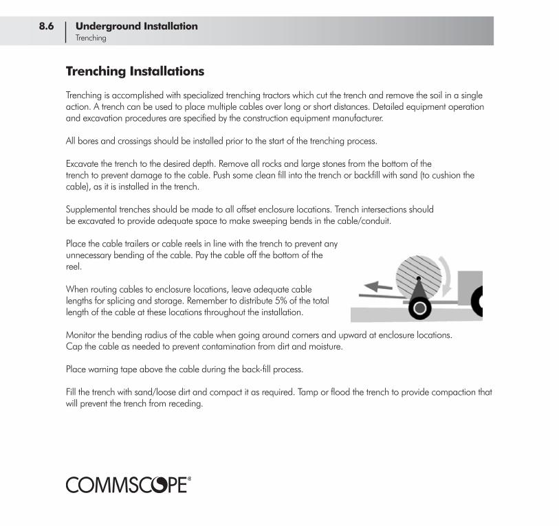
Trenching is accomplished with specialized trenching tractors which cut the trench and remove the soil in a single action. A trench can be used to place multiple cables over long or short distances. Detailed equipment operation and excavation procedures are specified by the construction equipment manufacturer.
All bores and crossings should be installed prior to the start of the trenching process.
Excavate the trench to the desired depth. Remove all rocks and large stones from the bottom of thetrench to prevent damage to the cable. Push some clean fill into the trench or backfill with sand (to cushion the cable), as it is installed in the trench.
Supplemental trenches should be made to all offset enclosure locations. Trench intersections shouldbe excavated to provide adequate space to make sweeping bends in the cable/conduit.
Place the cable trailers or cable reels in line with the trench to prevent any unnecessary bending of the cable. Pay the cable off the bottom of the reel.
When routing cables to enclosure locations, leave adequate cable lengths for splicing and storage. Remember to distribute 5% of the total length of the cable at these locations throughout the installation.
Monitor the bending radius of the cable when going around corners and upward at enclosure locations.Cap the cable as needed to prevent contamination from dirt and moisture.
Place warning tape above the cable during the back-fill process.
Fill the trench with sand/loose dirt and compact it as required. Tamp or flood the trench to provide compaction that will prevent the trench from receding.
8.6 Underground Installation Trenching

Underground Installation 8.7 Boring
Boring Installations
Conventional BoresMechanical boring machines may be utilized to push a drill stem to make an adequate cable passage.Pneumatically driven pistons may be used as well. Conduit should be placed to support the tunnelwall and allow cable placement.
Directional BoresDirectional boring is accomplished by using a steerable drill stem. The depth and direction of the boring can be controlled by the equipment operator. Very long bore lengths can be accomplished by using directional boring devices.
Subsurface crossings are generally accomplished by digging a trench on each side of the crossing to allow the guiding and retrieval of the drill stem. Detailed equipment operation and excavation procedures are specified by the construction equipment manufacturer.
Generally, try to keep the bore as straight as possible. The hole may be enlarged by using reamers.Conduit should be installed at strategic locations (i.e. street crossings).
After the bore is complete, attach the fiber optic cable to the drill stem with the appropriate cablegrip and swivel. Pull the drill stem/cable through the bore. Longer pulls will require tension monitoring.
ConQuest®
cable-in-conduitis an excellent
system forinstalling cable
in bores

Installing Fiber Optic Cable in Conduit
Cable can be pulled in new or existing ductwork. New conduit should be installed in as straight a path aspossible - undulations in the conduit system increase pulling tensions due to sidewall pressure. Existing conduit systems generally require some maintenance prior to placing cables into the conduit. Always clean the route prior to installation. Use a rodding machine to remove unwanted debris and water from the conduit.
A cable route survey will dictate the cable placement scheme that should account for the difficultyof the pull, manpower and equipment availability.
The curve radius in the conduit systems should be large enough to prevent excessive pulling tension due to sidewall friction. The use of pulling lubricants (such as CommScope’s WHUPP!TM) is recommended to reduce friction and pulling tension. Very small radius bends may prevent even a cable as flexible as CommScope fiber optic from being successfully pulled.
Blowing/Jetting Fiber Optic CableThis process uses a combination of air pressure and a small drive to push fiber optic cable through aconduit. It is most effective when placing a single cable. Since the cable is not pulled, pulling tensionis not a concern.
Position the reel so the pay-off is from the top and is in as straight a line as possible with the entrance to the conduit. A small caterpillar drive pushes 150 - 200 feet (45 - 60 meters) of cable into the conduit. Air is then forced into the conduit and the jetting action helps propel the cable with minimum effort.
With this method, a flexible cable like dielectric Central Tube can be pushed through several 90° sweeps over a 1,500 foot (450 meter) distance of 2 inch (5 cm) rigid PVC conduit.
8.8 Underground Installation Fiber Cable in Conduit

Long Pulls Through Conduit -Pulling in Stages to Intermediate Locations
If capstans or other mechanical devices are not available or practical to assist the pull, you can reducethe overall tension by pulling the cable in stages to intermediate locations.
Underground InstallationLocate the midway point of the pull. While monitoring the tension, pull the cable from the mid-point to an interme-diate vault or manhole. Pay the cable up to the surface.
Set up two traffic cones about 10 - 15 paces apart (more for larger cables). Loosely weave the cable around the cones in a figure-8 pattern. Large re-laxed loops will help you avoid tangling the cable.
Walking Over the Figure-8Once you’ve stopped pulling, ‘walk’ the figure-8 over. Be careful - a figure-8 may weigh several hundred pounds.
The cable end should now be at the top of the fig-ure-8. Prepare the cable end for pulling toward the next intermediate location or the end of the pull.
When you resume the pull, the cable will pay off the top of the figure-8. (The cable end moves to the top of the pile.)
Underground Installation 8.9 Pulling in Stages/Walking the Reel Over

Long Pulls Through Conduit - Mid-Point Pulling TechniqueCommScope fiber optic cables can be ordered in lengths of up to 7.5 miles (12.2 km) and can be installed in one continuous run. However, even a typical installation of 3 - 5 miles (4.8 - 8.0 km) offers installation challenges because of the accumulation in pulling tension along such a long route. A midpoint cable pull is a proven method for installing long lengths of fiber optic cable.
Mid-point Cable Pull
Locate the midway point of the pull. While monitoring the tension, pull the cable from the mid-point to the end of one direction. The pull may be assisted at an intermediate vault by a capstan or a craftsman.
Prepare to figure-8 the remaining cable. Set up two traffic cones about 10 - 15 paces apart (more for larger cables). Pay the cable off the top of the reel and loosely weave it around the cones in a figure-8 pattern. Large relaxed loops will help you avoid tangling the cable. Continue to figure-8 the cable until the remainder of the reel is payed off. Remove the cones.
Prepare the cable end in your hand for pulling toward the other end of the installation. When you resume the pull, the cable will pay off the top of the figure-8.
9.1 ConQuest® Installation Midpoint Pulls/Setup

Fiber Splicing 10.1 Fiber Preparation
Splicing Fiber Optic Cables - Fiber Preparation
Trim the Buffer TubeThe buffer tube must be carefully trimmed to reveal the fibers. Use a buffer tube cutter to score the buffer tube in intervals of 12 - 16 inches (30 - 40 cm). Flex the buffer tube back and forth until it snaps, then slide the tube off the fibers. The splice enclosure instruction will tell you how far back to removethe buffer tubes.
Fiber StrippingThe exposed fiber can now be stripped. CommScope fiber optic cables use a 125 µm singlemode fibercoated to an industry standard 250 µm. A fiber stripping tool will cleanly remove the outer coating.Do not try to remove any more than 2 inches (5 cm) at one time.
Once a fiber is stripped, it needs to be cleaned with 99% isopropyl alcohol and a lint-free cloth to remove the coating residue. Keep handling of bare fibers to a minimum. Once cleaned, cleave and splice the fiber as soon as possible in order to reduce the fiber’s contact with airborne contaminants.
Fiber CleavingCleave the fiber end using a quality fiber cleaver. The cleave should be clean (devoid of chips and lips)and be within 1° of perpendicular. Try to leave as little bare, uncoated fiber as possible (no more than1/2 inch [1.25 cm]). Some fusion splicers come with their own cleavers attached. Smaller hand-heldcleavers (called beaver tail cleavers) are not recommended for precision cleaves.

Splicing Fiber Optic Cables - Fusion Splicing
Fusion SplicersThere are several brands of fusion splicers available. Most integrate features such as:
• a fusion heat source, usually an electric arc • V-groove clamps for holding the fibers • a way of positioning the fibers relative to themselves and the heat source • a way of viewing the fibers (microscope, display screen) so they can be accurately positioned
Procedures will vary depending on the fusion splicer used. The older models require you to manually match up the outer diameters of the cleaned fibers before fusing them. More sophisticated ones offer features that automatically align the fiber cores for the lowest loss splices.
LID (Local Injection and Detection)Some splicers come equipped with LID in which the fibers to be fused are coiled around a small postso that light can actually be ‘injected’ through the fiber coating. The light crosses through the alignmentpoint and is measured on the output side. The fibers are then manually or automatically positioneduntil the most light is passing through the aligned fibers. LID systems also monitors the fibersas they are being fused and shut off the arc when the process shows the lowest splice loss.
PAS (Profile Alignment System)Splicers equipped with PAS project an image that allows you to view the fiber cores and manually orautomatically bring them into alignment.
Splice ProtectionCommScope recommends that the spliced fibers be mechanically reinforced. A heat-shrink sleeveis placed over the fiber prior to splicing. Once the splice is completed, the sleeve is placed overthe splice and shrunk. There are other methods such as crimpable sleeves, splints and sealants; experience will show which work best for your application.
10.2 Fiber Splicing Fusion Splicing

Emergency Restoration 11.1 Trouble Shooting
Emergency Restoration - Troubleshooting the Problem
There are several reasons for all or any part of a system to ‘go dark.’ The reason may be obvious, such as a falling tree shearing a span. More often than not, the reasons may not be that apparent. The first step in restoration is to determine exactly what and where the problem is located. The methodical approach described below is the wisest way to determine the cause of the outage. All records of installation parameters should be easily available:
Check the Transmitter - Measure the transmitter output at the output connector with an opticalpower meter. Check the received power to that recorded at installation.
Check Patchcords at the Transmitter End - Patchcords, connectors and sleeves may be damagedor defective. Replace suspect patchcords with known good ones and measure the output powercompared to installed values.
Check Patchcords at the Receiver End - Repeat the process above at the far end of the system.Replace suspect patchcords with known good ones and measure the output power compared toinstalled values. If the power is within prescribed limits, the problem is in the receiver.
Check the Cable Plant - This can be done from either end of the system with an OTDR. Comparethe OTDR trace with the as-built documentation. This will often show you to within a few yardswhere the problem might be.
Unfortunately, many problems turn out to be a catastrophic failure of the cable. Common causesinclude rodent damage, lightning strikes, trees falling on the cable, traffic accidents, gunshots orother vandalism. Mechanical causes could be freezing water in conduit, failed splices or environmentaldamage within a splice closure. In many cases, a short span of cable may need to be replaced quicklyto restore service.

Emergency Restoration - Material Checklist
Action can be taken once the location and nature of the problem have been determined. It may bepossible to transfer the signal to an undamaged dark fiber within the cable. However, you should beprepared to do a full on-site restoration.
If the problem is with a downed pole placed on a utility ROW, make sure the ROW owner is alerted to the problem. It is important to have an agreement with the ROW owner that gives a high priority to the repair of the poles you share.
Preparedness is the Key to Quick RestorationPrior to the emergency, you should have designated a trained response team of fiber technicians(usually three in number) as well as a secondary technician team. A current notification list should bemade available to designated personnel. Unannounced practice sessions will help with proficiency.
The fiber technicians should have lock-and-key access to an emergency restoration kit. A complete list of kit materials should be displayed at the storage site. The kits should be inventoried quarterly. Any missing or out-of-date materials should be replaced IMMEDIATELY. While kits can be purchased, they can be assembled with the following items:
Cable components Splice trays Splice closures About 300 ft/100 of prepped fiber cable 2x mechanical splices as fibers in the cable
System documentation City/county map with receiver/splice locations clearly noted ‘Hot fibers’ list with routing documentation
Master maintenance/restoration log with as-built or repaired fiber data
Two Tool/Supply Kits With: Isopropyl alcohol packs Needlenose pliers Gel remover Wrenches Vinyl tape Screwdriver Mechanical stripping tool Cable sheath knife Book of numbers Hook blade knife Lint-Free wipes Cable ties Pliers Snips Precision fiber cleaver
11.2 Emergency Restoration Materials

Emergency Restoration 11.3 Aerial Restoration
Emergency Restoration - Aerial Installations
Pull in Excess Cable from the Slack LoopLocate the nearest excess/slack loop on the line. Unlash the cable from the span to the excess loop,being careful not to let the cable sag into traffic (or other areas where it could be damaged) and notto let the cable bend past its loaded bend radius.
Unlash the cable on the other side of the break to free enough cable to reach the ground.While emergency splicing can be performed on the pole, it is easier to do it in a splicing van or tent.
If slack loops are not available to you, patch the cable with the 300 ft (100 m) of prepared cable fromyour emergency restoration kit.
Splice With Mechanical SplicesCut away the damaged ends of the cable. Strip away the jacket and prepare the cable per the instruction with your emergency splice enclosure. Your emergency restoration kit should contain splice enclosures and trays adapted for mechanical splices. Prepare the fiber ends for splicing, noting any changes in technique mentioned in the instructions for the mechanical splices. If at all possible, loop the cable and suspend it from the pole out of harm’s way.
Mark and Protect the CableFor emergency purposes, or in cases where the pole line has been damaged, it is permissible to leavethe cable on the ground out of the way of vehicle or foot traffic. Make sure the area is clearly markedwith cones or tape. Restore the pole line as soon as possible. If needed, reinstall a new span of cable.

Emergency Restoration - Underground Installations
Direct Buried InstallationsFrom the site of the intrusion, dig back in both directions to where the cable has not been disturbed.Place a manhole or vault at this point. Free up enough cable for handling and splicing purposes byCAREFULLY digging around the undisturbed cable. When moving the cable, do not let the cable bendexceed its loaded bend radius. Use the 300 ft (100 m) of prepared cable from your emergency restorationkit to connect the broken cable.
Conduit and Ductwork InstallationsLocate the nearest excess/slack loops on both sides of the break. Pull enough cable from both directions to accommodate splicing. Place a manhole or vault at this point. If slack loops are not available to you, patch the cable with the 300 ft (100 m) of prepared cable from your emergency restoration kit.
Splice with Mechanical SplicesCut away the damaged ends of the cable. Strip away the jacket and prepare the cable per the instructions with your emergency splice closures. Your emergency restoration kit should contain splice closures and trays adapted for mechanical splices. Prepare the fiber ends for splicing (see pages 9.1 to 9.3), noting any changes in technique mentioned in the instructions for the mechanical splices.
Mark and Protect the CableFor emergency purposes, it is permissible to leave the cable on the ground out of the way of vehicleor foot traffic. Make sure the area is clearly marked with cones or tape. If needed, reinstall a newspan of cable as soon as possible.
11.4 Emergency Restoration Underground Restoration

Midsheath Entry 12.1 Overview
Midsheath Entry of Fiber Optic Cables -Preparation and Jacket Removal
Some installations require that you ‘branch off’ some of the fibers in a cable between points oftermination. This is called a branch splice. To access fibers along a span, use a midsheath entry procedure.
Determine Choke Points/Cut the JacketFor midsheath entry, first determine the amount of jacket to remove - typically, this will be between 3and 6 yards (2.8 and 5.1 meters). The amount may vary depending on the splice enclosure to be used;check the enclosure instructions.
Measure and mark the cable at the ends of the proposed entry points with two turns of vinyl tape.These are called the choke points. Using a hook blade knife, CAREFULLY make a ring cut through thejacket at the choke points. In a dielectric cable, E-glass yarn will be the only protection for the buffertubes. Therefore, take extreme care not to nick or cut the buffer tube(s).
Remove the JacketFree the ripcord by carefully notching the jacket about 6 inches (15 cm) from one choke point. Cut theripcord at the choke point. Pull the ripcord through the notch and wrap it around the shaft of ascrewdriver. Using the screwdriver as a handle, pull the ripcord to the other choke point. Carefullyremove the jacket. Cut off the excess ripcord with scissors.
Midsheath Entry of Fiber Optic Cables - Buffer Tube EntryRemove Filler TubesFiller tubes have no fibers in them and should be cut at the choke points and removed. Be careful notto mistake an active white buffer tube for a filler tube; the white tube is located between the slateand red tubes.
Trim the Central Member and Anchor the Cable in the EnclosureUse diagonal side cutters to trim the central support member at each choke point to the length specified by the enclosure manufacturer. Some enclosures require that the central member be stripped of its coating. The central member will be used to secure the cable in the enclosure. Anchor the cable according to enclosure instructions.
Cut the Tubes and FibersIn stranded loose tube cables with live fibers within the tube being cut, slit the buffer tube carefully removing the buffer tube material. Separate the live fibers from the fibers to be cut, and prepare the fibers for splicing as detailed below.
In stranded loose tube cables in which the entire tube can be cut, cut the buffer tubes and fibers midway between the choke points. To access the fibers, use a buffer tube cutter to score the buffer tube at intervals of 12 - 16 inches (30 - 40 cm). Flex the buffer tube back and forth until it snaps, then slide the tube off the fibers. The splice enclosure instructions will tell you how far back to remove the buffer tubes.
In central tube and drop cables, use a buffer tube slitter to open and remove the tube without cutting the fibers. Once the tube is removed, cut the fibers you intend to break out.
Clean the Fibers/Prepare for SplicingAfter the buffer tube has been removed, clean the fibers with 99% isopropyl alcohol. Prepare thefibers for splicing (see pages 10.1 and 10.2). You will probably be using some type of branch splice enclosure to accommodate another cable. Prepare the second (branch) cable for termination and its fibersfor splicing.
12.2 Midsheath Entry Fiber Preparation

Plant Maintenance 13.1 Overview
Fiber Plant Maintenance
CommScope fiber optic cable actually requires very little maintenance once installed. However, periodic inspection may reveal small problems that can be corrected before they become large ones.
Maintenance TestingIt is recommended that all the cable in your system be tested with an OTDR at least once every two years.A good practice would be to test every time you take the transmitter down for maintenance. Comparing these test results with the final inspection tests permit you to identify and correct gradual losses in performance before they become the cause for an outage.
Aerial Trunk and Distribution CableWorn or broken lashing wire can create serious performance problems, such as wind-caused deformation which can impact the performance of the cable. Loose lashing can also be the cause of jacket abrasion over long lengths of cable which can cause water to migrate through cracks in the jacket and lead to mechanical breakdown. If this sort of damage is detected, CommScope recommends that the entire span be replaced.
Underground Trunk and Distribution CableInspect cable where possible in vaults and manholes. Check the plant periodically with an OTDR to see if there is any sign of degraded performance. Replace any damaged cable.

Occupational Safety And Health Administration (OSHA) Standards
OSHA Standards were established in 1970 to help ensure workplace safety. The Standards are federal regulations that are intended to enable employees to recognize, understand and control hazards in the workplace. Standards have been established for general industry while some sections of the Standards are dedicated to specific industries such as telecommunications.
The general applicable OSHA Standards are found in:
Title 29 CFR Parts 1901.1 to 1910.399 General Industry, Part 1926 Safety and Health Regulations for Construction.
Most relevant is Title 29 CFR Part 1910 Occupational Safety and Health Standards
Copies of OSHA standards can be obtained from:
US Department of LaborOSHA PublicationsPO Box 37535Washington, DC 20013-7535(202) 693-1888(202) 693-2498 faxwebsite: www.osha.gov
14.1 Appendix OSHA Standards

Appendix 14.2 NEC Standards
National Electric Code (NEC) Standards
The NEC typically identifies the construction techniques and materials necessary in building wiring require-ments, i.e., inside plant construction, of fiber optic, coaxial cable, or twisted pair systems. The NEC has been developed by the National Fire Protection Association’s (NFPA’s) National Electric Code committee. Committee members are professionals from the electrical industry. The NEC addresses safety from fire and electrocution. The NEC has been adopted by the American National Standards Institute (ANSI).
Copies of NEC standards can be obtained from:
National Fire Protection Association1 Batterymarch Park/P.O. Box 9146Quincy, MA 02269-3555(800) 344-3555website: www.nfpa.org

National Electric Safety Code (NESC) Standards
The NESC covers supply and communication cables and equipment in underground buried facilities. The rules also cover the associated structural arrangements and the extension of such facilities into buildings.
The NESC typically identifies the construction techniques and materials necessary in outside plant construction of electric supply or communication cable systems. The NESC is an American National Standard that has been written by a group of professionals that are concerned about the Standard’s scope and provisions. The NESC has been adopted by the American National Standards Institute (ANSI). All references to the NESC in this manual are from the 2007 edition.
Special attention should be given to NESC Part 3 Safety Rules for the Installation and Maintenance of Underground Electric Supply and Communication Lines.
Copies of NESC standards can be obtained from:
IEEE Service Center445 Hoes Lane/P.O. Box 1331Piscataway, NJ 08855-1331(800) 678-4333website: www.ieee.org
14.3 Appendix OSHA Standards

Equipment/Blocks
Multiple Cable BlockUsed to support multiple cables in independent rollers. Multiple cable blocks make a cable positioner unnecessary when lashing multiple cables.
Single Roller BlockTypically used to support a single cable prior to lashing and may be used when cables are lashed directly to strand or in overlash applications. In new strand situations, single roller blocks may be locked onto the strand. In over-lash applications, this block should not be pushed in front of the lasher.
Economy BlockUsed to support a single cable prior to lashing and, depending on the actual block, may be used when cables are lashed directly to strand or in overlash applications.
Pole MountCable BlockUsed to install self- support cable and is attached to the pole hardware to support the cable as it is pulled out.
NOTE: Take care that cable slack does not exceed the minimum bend radius over blocks.
Appendix 14.4 Equipment/Blocks
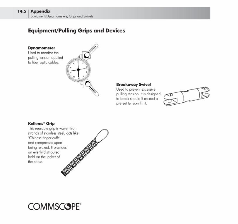
Equipment/Pulling Grips and Devices
Kellems® GripThis reusable grip is woven from strands of stainless steel, acts like ‘Chinese finger cuffs’ and compresses uponbeing relaxed. It providesan evenly distributedhold on the jacket ofthe cable.
DynamometerUsed to monitor thepulling tension applied to fiber optic cables.
Breakaway SwivelUsed to prevent excessive pulling tension. It is designed to break should it exceed a pre-set tension limit.
14.5 Appendix Equipment/Dynamometers, Grips and Swivels

Appendix 14.6 Equipment/Blocks, Chutes and Brackets
90° Corner BlockUsed to route cables through inside or outside corners up to 90°. It minimizes drag on the cable in corners and ensures that the minimum bend radius of the cable is not exceeded. Requires specialized mounting hardware depending on the specific use of the equipment.
45° Corner BlockUsed to route cables through inside or outside corners up to 45°. It minimizes drag on the cable in corners and ensures that the minimum bend radius of the cable is not exceeded. 45° corner blocks should be used as a set-up chute to guide cables from the cable trailer or a reel stand. Requires specialized mounting hardware depending on the specific use of the equipment.
Equipment/Blocks, Chutes and Brackets
Set-Up ChuteA set-up chute is used to guide cables from the cable trailer or reel stand. This equipment requires specialized mounting hardware depending on the specific use of the equipment.
Set-Up BracketThis bracket is used to support 45° and 90° corner blocks or set-up chutes at mid-span.

Cable Positioner(or Magic Box)Pushed in front of a lasher by a cable block pusher to uniformly position multiple cables that are being lashed.
Cable GuideUsed to guide the cable into the lasher in drive-off applications. Can be used for new strand or overlash applications. The guide may be pushed in front of the lasher with a cable block pusher, pulled in front of the lasher or physically attached to the lasher, dependent on the cable guide type.
Cable LasherUsed to lash cable directly to installed strand or cable bundles. Lashers are some-what specific to cable and strand size - improper lasher size or adjustment may damage cables.
Multiple Cable PullerAllows multiple cables to be pulled into place when lashing cables directly to strand. It’s equipped with a strand brake to prevent sagging of cables as the pulling tension is released. Allows pulled cables to independently swivel.
Overlash Cable PullerAllows multiple cables to be pulled into place in over-lash applications. Allows pulled cables to indepen-dently swivel.
Equipment/Lashers, Pullers, Positioners and Guides
Cable Block Pusher(or Shotgun or Shuttle)
Used to push equipment ahead of a pulled lasher.
14.7 Appendix Equipment/Lashers, Pullers, Positioners and Guides
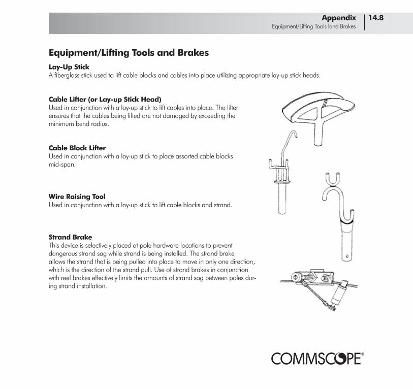
Appendix 14.8 Equipment/Lifting Tools land Brakes
Equipment/Lifting Tools and BrakesLay-Up StickA fiberglass stick used to lift cable blocks and cables into place utilizing appropriate lay-up stick heads.
Cable Lifter (or Lay-up Stick Head)Used in conjunction with a lay-up stick to lift cables into place. The lifter ensures that the cables being lifted are not damaged by exceeding the minimum bend radius.
Cable Block LifterUsed in conjunction with a lay-up stick to place assorted cable blocks mid-span.
Wire Raising ToolUsed in conjunction with a lay-up stick to lift cable blocks and strand.
Strand BrakeThis device is selectively placed at pole hardware locations to prevent dangerous strand sag while strand is being installed. The strand brake allows the strand that is being pulled into place to move in only one direction, which is the direction of the strand pull. Use of strand brakes in conjunction with reel brakes effectively limits the amounts of strand sag between poles dur-ing strand installation.

Equipment/Fiber Preparation and Splicing
Buffer Tube CutterThese are used to score drop, central tube and stranded loose tube buffers to facilitate exposing the fibers.
Coating StripperThis device mechanically strips fiber coating using pre-cision blades and preset openings in much the same way as a wire stripper takes insulation off a copper wire. After the coating has been stripped, the fiber is cleaned with a solution of 95% or higher isopropyl alcohol.
Fiber Cleaver (Hand Held)Fiber cleavers score and then trim the fiber. Price and complexity of cleavers vary widely - generally, the more you spend, the greater the consistency of the cleave. The beaver tail cleaver shown is a lower cost model.
Fiber Cleaver (Free Standing)This is a larger and more expensive version of a cleaver. Its main advantage is that it performs accurate cleaves more consistently than the hand-held models.
Fusion SplicerMost low-loss splices are made with fusion splicers, which use an electric arc to fuse together the cleaved ends of fibers. Splicers vary widely in complexity, features and price. Some automate the entire splicing process. An applicable splicer for CommScope fiber optic cables would have:
• a fusion heat source, usually an electric arc • V-groove clamps for holding the fibers • a way of positioning the fibers for optimum splicing • a way of viewing the fibers (microscope, display screen) so they can be accurately positioned • LID (Local Injection and Detection) and/or PAS (Profile Alignment System) to aid with fiber alignment
14.9 Appendix Equipment/Cutting and Stripping

Installation - Back-Pull/Stationary Reel Set-Up
The back-pull/stationary reel method is the usual method of cable placement. The cable is run from the reel up to the strand, pulled by a device that only travels forward and is held aloft by cable blocks. Excess (slack) loops are formed during the pull. Lashing takes place after the cable is pulled.
Set-Up Roller-Block PlacementThe set-up block should be positioned on the first pole of the cable route. Do not position set-up or take-down blocks on the span. They should only be placed on a pole. Placement of the set-up block should keep the cable from rubbing on the reel or pole. A 45° roller block should be used at the set-up pole.
Trailer Set-UpThe trailer should be positioned in-line with the strand and twice the distance of the set-up block to the ground from the chute. This prevents the cable from rubbing on the pole (or reel) or binding on the block. If the trailer cannot be positioned there, move the set-up block and cable trailer to an adjacent pole.
The cable should pay-off the top of the cable reel. The pay-off of the cable from the reel should cause a downward force at the hitch of the trailer.
Chock the trailer wheels. Adjust the reel brakes as needed. Place protective barriers and cones as needed to protect pedestrians.
Appendix 14.10 Back-Pull/Stationary Reel Set-Up

Legal DisclaimerTHIS MANUAL IS PROVIDED FOR GUIDANCE PURPOSES ONLY AND SHOULD NOT BE USED OR IN ANY WAY RELIED UPON WITHOUT CONSULTATION WITH AND SUPERVISION OF EXPERIENCED CONSTRUCTION PERSONNEL, ENGINEERS OR NETWORK DESIGN SPECIALISTS. COMMSCOPE MAKES NO REPRESENTATIONS OR WARRANTIES OF ANY KIND, EXPRESS OR IMPLIED, INCLUDING ANY REPRESENTATION OR WARRANTY REGARDING THE QUALITY, CONTENT, COMPLETENESS, SUITABILITY, ADEQUACY OR ACCURACY OF THE DATA CONTAINED HEREIN. COMMSCOPE IS UNDER NO OBLIGATION TO ISSUE ANY UPGRADES OR UPDATES OR NOTIFY CUSTOMERS/USERS OF THIS MANUAL THAT CHANGES HAVE BEEN MADE TO THIS MANUAL. THE USER OF THIS MANUAL ASSUMES ALL RISKS ASSOCIATED WITH SUCH USE, AND COMMSCOPE HEREBY DISCLAIMS ANY AND ALL LIABILITY FOR DAMAGES OF ANY KIND RESULTING FROM SUCH USE.
Disclaimer

www.commscope.comVisit our website or contact your local CommScope representative for more information.
© 2014 CommScope, Inc. All rights reserved.
All trademarks identified by ® or ™ are registered trademarks or trademarks, respectively, of CommScope, Inc. This document is for planning purposes only and is not intended to modify or supplement any specifications or warranties relating to CommScope products or services.
CO-107147.2-EN (11/15)