broadband services and impacts to the network
TRANSCRIPT

Broadband services and impacts to the network infrastructures, network architectures vs. services.
• Support for Quality of Service on streaming services
DIPLOMA THESIS
PETER ŠIMURKA
UNIVERSITY OF ŽILINA Faculty of Electrotechnics
The Department of Telecommunications
Field of study: TELECOMMUNICATIONS
Diploma thesis supervisor: doc. Ing. Martin Vaculík, PhD.
Degree: Engineer Date of delivery: 18.5.2006
Žilina 2006
Abstract Streaming as a broadband service has undoubtedly contributed to the architecture changes
not only in the access but also in the core networks. The work presented in this thesis
describes analysis of streaming, discusses Quality of Service and its parameters, provides
a detailed discussion on important Internet multimedia protocols and mechanisms that are
intending to improve the QoS of real-time streaming applications. The thesis also
explores architecture changes in mobile networks and Quality of Service in these
networks. At the end of this thesis I am commenting existing streaming services and
proposing new ones. Combined results of the work presented in this thesis strongly
contribute to the understanding of improvement QoS for future streaming applications
over the Internet and shows architecture changes witch have been implemented to mobile
networks in order to build a packet-based mobile cellular network.
Abstrakt Streaming ako širokopásmová služba nepochybne prispela k zmenám v architektúre
nielen v prístupových, ale aj chrbticových sieťach. V mojej diplomovej práci sa postupne
zaoberám analýzou streamingu, potrebou vzniku ale aj samotnou kvalitou služby, ktorá je
pre real-time aplikácie nevyhnutná. Popisujem protokoly potrebné pre multimediálne
aplikácie ako aj mechanizmy zabezpečenia resp. zvýšenia kvality služby v Internet.
Taktiež sa zaoberám zmenami architektúry v mobilných sieťach ako aj ich kvalitou
služby. V poslednej kapitole popisujem služby pracujúce na princípe streamingu
a navrhujem nové oblasti resp. možnosti využitia streamingu v mobilných sieťach.
Cieľom tejto práce je prispieť k problematike kvality služby v pevných dátových sieťach
ako je Internet, ale aj k zmenám v architektúre mobilných sieti poukázaním na službu
streaming.

Žilinská univerzita v Žiline, Elektrotechnická fakulta, Katedra telekomunikácií
______________________________________________________________________________
ANOTAČNÝ ZÁZNAM - DIPLOMOVÁ PRÁCA
Priezvisko, meno: Šimurka Peter školský rok: 2005/2006 Názov práce : Broadband services and impacts to the network infrastructures, network architectures vs. services.
• Support for Quality of Service on streaming services
Počet strán: 55 Počet obrázkov: 29 Počet tabuliek: 16
Počet grafov: 2 Počet príloh: 0 Použitá lit.: 27
Anotácia (slov. resp. český jazyk):
Analýza Streamingu, Kvalita Služby, Multimediálne Protokoly,
Podpora kvality služby v pevných a mobilných sieťach.
Anotácia v cudzom jazyku (anglický resp. nemecký):
Analyse of Streaming, Quality of Service, Internet Multimedia Protocols,
Real-Time Streaming in the Internet, Real-Time Streaming in Mobile Networks.
Kľúčové slová:
Streaming, Quality of Service, Multimedia Protocols, Network Layer QoS,
Application Later QoS, GSM, GPRS, UMTS
Vedúci práce : doc. Ing Martin Vaculík, PhD.
Recenzent práce : Ing. Róbert Hudec Dátum odovzdania práce : 18.5.2006
Acknowledgements I would especially like to thank my supervisor doc.Ing. Martin Vaculík,PhD. for his
initial inspiration and ongoing guidance. I am grateful to Orange Slovakia, a.s. for thesis
proposal.
I would also like to express great appreciation to my family and other family friends not
mentioned here who continued to provide support and encouragement. Finally, and most
especially I would like to thank my girlfriend Danka Vajdová for supporting me with
encouragement and care throughout this time.
Žilina, May 2006 Peter Šimurka

Contents 1 Introduction 1 1.2 Traffic Classification ....................................................................................... 3 2 Analyse of Streaming 5 2.1 Principle of Streaming ...................................................................................... 5 2.2 Process of Creating Streaming File................................................................... 6 2.3 Streaming Media Delivery Methods................................................................. 7 2.4 Summary .......................................................................................................... 8 3 Quality of Service 9 3.1 QoS ................................................................................................................... 9 3.2 QoS Parameters.................................................................................................. 10 3.3 Causes of Delay ................................................................................................. 12 3.4 Causes of Jitter ................................................................................................... 13 3.5 Causes of Packet Loss........................................................................................ 14 3.6 Dynamic QoS Control........................................................................................ 15 3.7 Application QoS Requirements ........................................................................ 16 3.7.1 QoS Requirements for Real-Time Audio Streaming ................................ 16 3.7.2 QoS Requirements for Real-Time Video Streaming ................................ 19 3.8 Summary ............................................................................................................ 22 4 Internet Multimedia Protocols 23 4.1 Network Layer Protocols ................................................................................... 24 4.2 Transport Layer Protocols ................................................................................. 25 4.2.1 User Datagram Protocol............................................................................ 25 4.2.2 Transport Control Protocol ....................................................................... 26 4.2.3 Real-Time Transport Protocol .................................................................. 27 4.2.4 Summary ................................................................................................... 29 4.3 Reservation Protocols ........................................................................................ 30 4.3.1 RSVP ........................................................................................................ 31 4.4 Application Layer Protocols .............................................................................. 34 4.4.1 Hyper Text Transfer Protocol ................................................................... 34 4.4.2 Real-Time Streaming Protocol ................................................................. 34 4.4.3 Summary ................................................................................................... 35 4.5 Summary ........................................................................................................... 35 5 Real-Time Streaming in the Internet 37 5.1 Network Layer QoS ........................................................................................... 37 5.1.1 Service Marking ....................................................................................... 38 5.1.2 Differentiated Services.............................................................................. 39 5.1.3 IP Label Switching ................................................................................... 41 5.1.4 Integrated Services.................................................................................... 42 5.1.5 Integration of Differentiated and Integrated Services............................... 45 5.1.6 Summary ................................................................................................... 46 5.2 Application Layer QoS ...................................................................................... 48 5.2.1 Adaptation................................................................................................. 48 5.2.2 Receiver Buffering ................................................................................... 49 5.2.3 Summary ................................................................................................... 49
6 Real-Time Streaming in Mobile Networks 50 6.1 Streaming Technology in Mobile Communication Systems ............................ 50 6.2 Evolution of Mobile Networks ......................................................................... 54 6.3 Global System for Mobile Communication...................................................... 55 6.3.1 GSM Network Architecture..................................................................... 56 6.3.2 GSM Data Rates ...................................................................................... 58 6.3.3 Summary .................................................................................................. 58 6.4 General Packet Radio Service........................................................................... 59 6.4.1 GPRS Network Architecture.................................................................... 59 6.4.2 GPRS Data Rates ..................................................................................... 61 6.4.3 Quality of Service in GPRS ..................................................................... 62 6.5 Enhanced Data for GSM Evolution ................................................................... 64 6.5.1 Summary ................................................................................................... 65 6.6 Universal Mobile Telecommunication System.................................................. 67 6.6.1 UMTS Network Architecture .................................................................... 67 6.6.2 Quality of Service in UMTS...................................................................... 70 6.6.3 QoS mapping between UMTS and Differentiated Services ...................... 76 6.6.4 Summary .................................................................................................... 76 7 Streaming Services 77 7.1 Nowadays Streaming Services......................................................................... 77 7.1.1 Live TV Broadcasting............................................................................. 77 7.1.2 Live Radio Broadcasting......................................................................... 78 7.1.3 Video on Demand ................................................................................... 78 7.2 Future Streaming Services ................................................................................ 78 7.2.1 Mobile Advertisement ............................................................................ 79 7.2.2 Mobile Hot News.................................................................................... 79 7.2.3 Mobile Education.................................................................................... 79 7.2.4 Mobile Security....................................................................................... 80 7.2.5 Mobile Holiday & Entertainment ........................................................... 80 8 Final Remarks 81 8.1 Conclusions...................................................................................................... 81 Bibliography ............................................................................................................ 85

List of Figures 1.1 Traffic and Application Classification 2.1 Principle of Streaming 2.2 Process of creating Streaming File 3.1 Packet Clustering 4.1 Internet Multimedia Protocol Stack 4.2 The UDP Protocol Header 4.3 The TCP Protocol Header 4.4 The RTP Protocol Header 4.5 IP packet containing real-time data encapsulated in a UDP and RTP packet 4.6 Interaction between modules on a RSVP capable node and end host 4.7 A simple network topology with the data path from sender (H1) to the receiver (H2 and H3) and the reverse path from receivers to the sender 5.1 The meaning of ToS in IPv4 Header (Service Marking) 5.2 The meaning of ToS in IPv4 Header (Differentiated Services) 5.3 Differentiated Services Packet Classifier and Traffic Conditioner 5.4 The MPLS Header 5.5 The IntServ Reservation Request Format: FlowSpec and FilterSpec 5.6 Interoperation between IntServ and DiffServ 6.1 Overview of 3GPP Protocol Stack 6.2 Overview of 3GPP Streaming Client 6.3 Evolution of Mobile Networks 6.4 Different Access Methods used in Mobile Networks 6.5 The GSM Network Architecture 6.6 The GPRS Network Architecture 6.7 The UMTS Network Architecture 6.8 The UMTS Terrestrial Radio Access Network 6.9 QoS Mapping among GPRS and UMTS 6.10 The UMTS QoS Architecture 6.11 Different PDP context for each traffic class 6.12 QoS Mapping between UMTS and DiffServ

List of Tables 1.1 Heterogeneity of Various Application Requests 3.1 Voice Quality Encoding Techniques and Throughputs 3.2 Sound Quality Encoding Techniques and Throughputs 3.3 Video Quality Encoding Techniques and Throughputs 4.1 IPv4 vs. IPv6 4.2 Comparison of UDP, TCP and RTP-on-UDP as Transfer Mechanisms 4.3 RSVP Reservation Styles 6.1 Coding Schemes and Data Rates in GPRS (1TS) 6.2 Coding Schemes and Data Rates in GPRS for 1-8 TSs 6.3 Precedence Classes in GPRS 6.4 Reliability Classes in GPRS 6.5 Delay Classes in GPRS 6.6 QoS Profile for voice and video streaming at an aggregate bit rate of 39.8 kbps 6.7 Modulation Coding Schemes and Data Rates in EDGE 6.8 QoS Attributes for UMTS classes 6.9 QoS Profile for voice and video streaming at an aggregate bit rate of 57.8 kbps List of Graphs 6.1 Data Rates and Modulation Coding Schemes in EDGE (1 TS) 6.2 Comparison of data rates in EDGE and GPRS

Abbreviations 1xEV-DO 1x Enhanced Version-Data Only 1xEV-DV 1x Enhanced Version-Data/Voice 1xRTT 1x Radio Transmission Technology 2G Second Generation 3G Third Generations 3GPP Third-Generation Partnership Project ADPCM Adaptive Differential Pulse Code Modulation AuC Authentication Centre BSC Base Station Controller BSS Base Station Subsystem BTS Base Transceiver Station CDMA Code-Division Multiple Access CELP Code Excited Linear Prediction CIF Common Intermediate Format CS Coding Scheme CSD Circuit-Switched Data DiffServ Differentiated Services DPCM Differential Pulse Code Modulation DSCP Differentiated Service Code Point DVI Digital Video Interactive EDGE Enhanced Data for GSM Evolution EIR Equipment Identity Register FDMA Frequency-Division Multiple Access FTP File Transfer Protocol GGSN Gateway GPRS Support Node GPRS General Packet Radio Service GSM Global System for Mobile Communication GSM Global System for Mobile Communication HLR Home Location Register HSCSD High-Speed Circuit-Switched Data HTTP Hyper Text Transfer Protocol IETF Internet Engineering Task Force IntServ Integrated Services IP Internet Protocol IPv4 Internet Protocol version 4 IPv6 Internet Protocol version 6 ISP Internet Service Provider ITU-T International Telecommunications Union- Telecommunication Standardization Sector JPEG Joint Photographic Experts Group MCS Modulation and Coding Scheme MPEG Moving Picture Experts Group MPLS MultiProtocol Label Switching

MS Mobile Station MSC Mobile Switching Centre NSS Network and Switching Subsystem NTSC National Television Society Commitee OSI Open Systems Interconnection PAL Phase Alternating Line SECAM Sequnces de Couleurs a Memoire PCM Pulse Code Modulation PCU Packet Control Unit PDU Protocol Data Unit PHB Per-Hop Behaviour QoS Quality of Service RED Random Early Detection RFC Requests for Comments RSVP Resource Reservation Protocol RTCP Real-Time Transport Control Protocol RTP Real-Time Transport Protocol RTSP Real-Time Streaming Protocol SDU Service Data Unit SDP Session Description Protocol SGSN Serving GPRS Support Node SIP Session Initiation Protocol SLA Service Level Agreement SNDCP Subnetwork Dependent Convergence Protocol TE Terminal Equipment TCP Transport Control Protocol TDMA Time-Division Multiple Access ToS Type of Service UDP User Datagram Protocol UMTS Universal Mobile Telecommunication System UTRAN UMTS Terrestrial Radio Access Network VLR Visitor Location Register WAP Wireless Access Protocol WCDMA Wide-band Code Division Multiple Access WWW World Wide Web

Name: Peter Šimurka
Declaration I declare I have elaborated this thesis by myself, while being supervised by my thesis
supervisor doc.Ing Martin Vaculík,PhD. and I have only used the literature listed here.
I agree with my thesis to be loaned.
Žilina 18.5.2006 Peter Šimurka.
Chapter 1
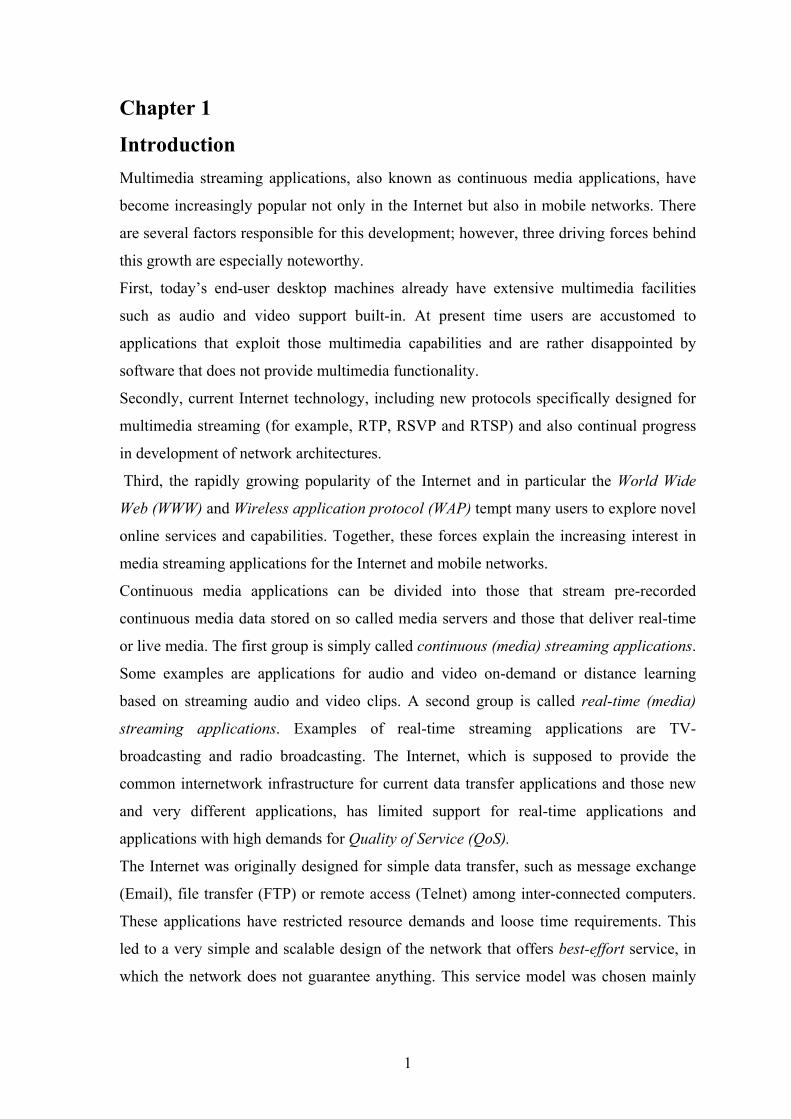
Introduction Multimedia streaming applications, also known as continuous media applications, have
become increasingly popular not only in the Internet but also in mobile networks. There
are several factors responsible for this development; however, three driving forces behind
this growth are especially noteworthy.
First, today’s end-user desktop machines already have extensive multimedia facilities
such as audio and video support built-in. At present time users are accustomed to
applications that exploit those multimedia capabilities and are rather disappointed by
software that does not provide multimedia functionality.
Secondly, current Internet technology, including new protocols specifically designed for
multimedia streaming (for example, RTP, RSVP and RTSP) and also continual progress
in development of network architectures.
Third, the rapidly growing popularity of the Internet and in particular the World Wide
Web (WWW) and Wireless application protocol (WAP) tempt many users to explore novel
online services and capabilities. Together, these forces explain the increasing interest in
media streaming applications for the Internet and mobile networks.
Continuous media applications can be divided into those that stream pre-recorded
continuous media data stored on so called media servers and those that deliver real-time
or live media. The first group is simply called continuous (media) streaming applications.
Some examples are applications for audio and video on-demand or distance learning
based on streaming audio and video clips. A second group is called real-time (media)
streaming applications. Examples of real-time streaming applications are TV-
broadcasting and radio broadcasting. The Internet, which is supposed to provide the
common internetwork infrastructure for current data transfer applications and those new
and very different applications, has limited support for real-time applications and
applications with high demands for Quality of Service (QoS).
The Internet was originally designed for simple data transfer, such as message exchange
(Email), file transfer (FTP) or remote access (Telnet) among inter-connected computers.
These applications have restricted resource demands and loose time requirements. This
led to a very simple and scalable design of the network that offers best-effort service, in
which the network does not guarantee anything. This service model was chosen mainly
1
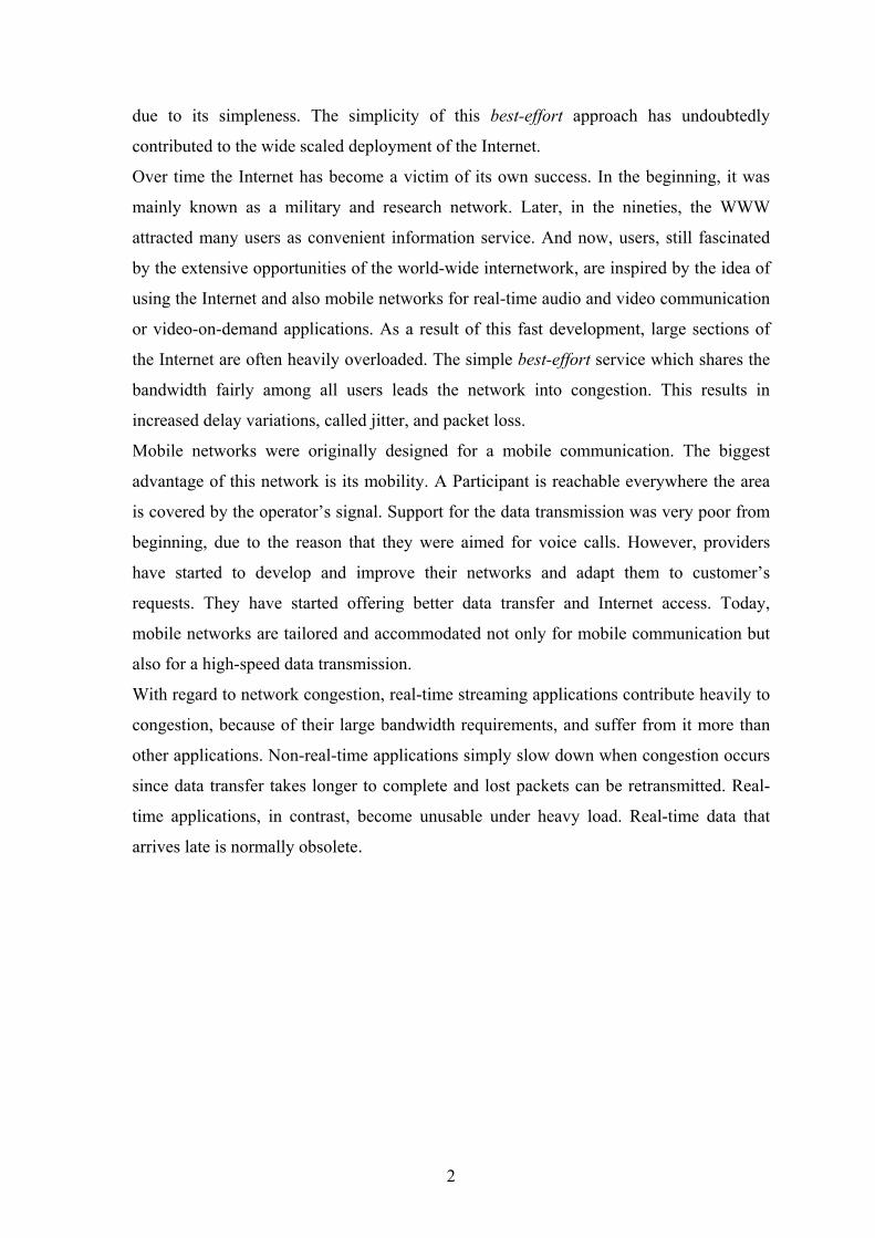
due to its simpleness. The simplicity of this best-effort approach has undoubtedly
contributed to the wide scaled deployment of the Internet.
Over time the Internet has become a victim of its own success. In the beginning, it was
mainly known as a military and research network. Later, in the nineties, the WWW
attracted many users as convenient information service. And now, users, still fascinated
by the extensive opportunities of the world-wide internetwork, are inspired by the idea of
using the Internet and also mobile networks for real-time audio and video communication
or video-on-demand applications. As a result of this fast development, large sections of
the Internet are often heavily overloaded. The simple best-effort service which shares the
bandwidth fairly among all users leads the network into congestion. This results in
increased delay variations, called jitter, and packet loss.
Mobile networks were originally designed for a mobile communication. The biggest
advantage of this network is its mobility. A Participant is reachable everywhere the area
is covered by the operator’s signal. Support for the data transmission was very poor from
beginning, due to the reason that they were aimed for voice calls. However, providers
have started to develop and improve their networks and adapt them to customer’s
requests. They have started offering better data transfer and Internet access. Today,
mobile networks are tailored and accommodated not only for mobile communication but
also for a high-speed data transmission.
With regard to network congestion, real-time streaming applications contribute heavily to
congestion, because of their large bandwidth requirements, and suffer from it more than
other applications. Non-real-time applications simply slow down when congestion occurs
since data transfer takes longer to complete and lost packets can be retransmitted. Real-
time applications, in contrast, become unusable under heavy load. Real-time data that
arrives late is normally obsolete.
2
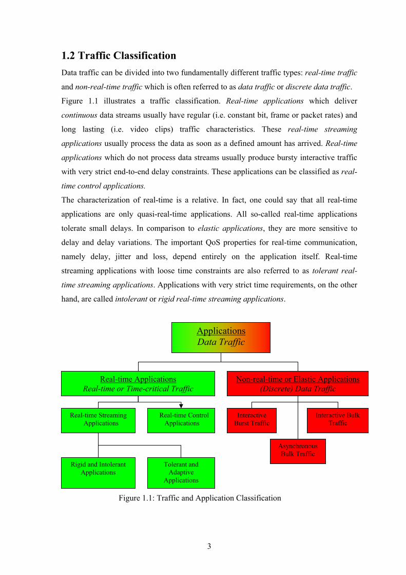
1.2 Traffic Classification Data traffic can be divided into two fundamentally different traffic types: real-time traffic
and non-real-time traffic which is often referred to as data traffic or discrete data traffic.
Figure 1.1 illustrates a traffic classification. Real-time applications which deliver
continuous data streams usually have regular (i.e. constant bit, frame or packet rates) and
long lasting (i.e. video clips) traffic characteristics. These real-time streaming
applications usually process the data as soon as a defined amount has arrived. Real-time
applications which do not process data streams usually produce bursty interactive traffic
with very strict end-to-end delay constraints. These applications can be classified as real-
time control applications.
The characterization of real-time is a relative. In fact, one could say that all real-time
applications are only quasi-real-time applications. All so-called real-time applications
tolerate small delays. In comparison to elastic applications, they are more sensitive to
delay and delay variations. The important QoS properties for real-time communication,
namely delay, jitter and loss, depend entirely on the application itself. Real-time
streaming applications with loose time constraints are also referred to as tolerant real-
time streaming applications. Applications with very strict time requirements, on the other
hand, are called intolerant or rigid real-time streaming applications.
Applications Data Traffic
Real-time Applications Real-time or Time-critical Traffic
Non-real-time or Elastic Applications (Discrete) Data Traffic
Real-time Streaming Applications
Real-time Control Applications
Interactive Burst Traffic
Interactive Bulk Traffic
Asynchronous Bulk Traffic
Rigid and Intolerant Applications
Tolerant and Adaptive
Applications
Figure 1.1: Traffic and Application Classification
3

Applications which have by their nature very strict QoS constraints can become tolerant
to QoS interruptions by means of adaptation. Rigid applications have a fixed playback
point, whereas adaptive applications are capable of adjusting their playback point
according to the observed network QoS. Elastic applications like Telnet, FTP, WWW,
Email, etc. produce discrete data traffic, where the individual data packets are sent
loosely coupled and without time constraints between each other. These applications
usually wait for certain amount of data to arrive, before starting to process them.
Therefore, long delays and jitter, as a result of bad network conditions, degrade the
performance, but do not affect the final outcome of the data transfer. Elastic applications
can be further classified according to their delay requirements. Bulk traffic (for example,
Email, News), asynchronously delivered in the background, operates well even with high
transmission delay. Interactive burst traffic, on the other hand, requires minimal delay to
achieve acceptable responsiveness. Interactive bulk traffic (for example, FTP, WWW)
operates well with medium delays.
(Discrete) Data traffic is known to be of a bursty nature. This is simply due to the fact
that elastic applications usually send out data as fast as the connection allows. Moreover,
these connections are usually very transient. They exist only to transfer one or at most a
few packets of data. As a result, data traffic is, in general, considered to be unpredictable.
Each type of application is prone to different QoS parameter. Some of them demand high
reliability and low bandwidth and another reverse. This heterogeneity of requests is
shown in Table 1.1
Applications Reliability Delay Jitter Bandwidth
E-mail High Low Low Low File transfer High Low Low Medium
Web access High Medium Low Medium
Remote login High Medium Medium Low
Audio on demand Low Low High Medium
Video on demand Low Low High High
Telephony Low High High Low
Videoconferencing Low High High High
Table 1.1: Heterogeneity of Various Application Requests
4

Chapter 2 Analyse of Streaming This chapter describes principle of streaming technology. It discusses about process of
creating streaming file as well as streaming media delivery methods.
2.1 Principle of Streaming Streaming is the process of playing a file while it is still downloading. Streaming
technology, also known as streaming media, lets a user view and hear digitized content
(video, sound and animation) as it is being downloaded [CC98]. Streaming is a
technology for playing audio and video files (either live or pre-recorded) from a
streaming server. A user can hear and view the audio or video files directly from server
for immediate playback.
When audio or video is streamed, a small buffer space is created on the user's device
(personal computer, notebook, mobile phone or PDA), and data starts downloading into
it. See Figure 2.1. As soon as the buffer is full (usually just a matter of seconds), the file
starts to play. As the file plays, it uses up information in the buffer, but while it is playing,
more data is being downloaded. As long as the data can be downloaded as fast as it is
used up in playback, the file will play smoothly.
Figure 2.1: Principle of Streaming
The Principle of Streaming (A snapshot in time)
The entire streaming video or audio file
The portion on your hard at one time
The portion you are viewing The portion in the buffer
Time
5
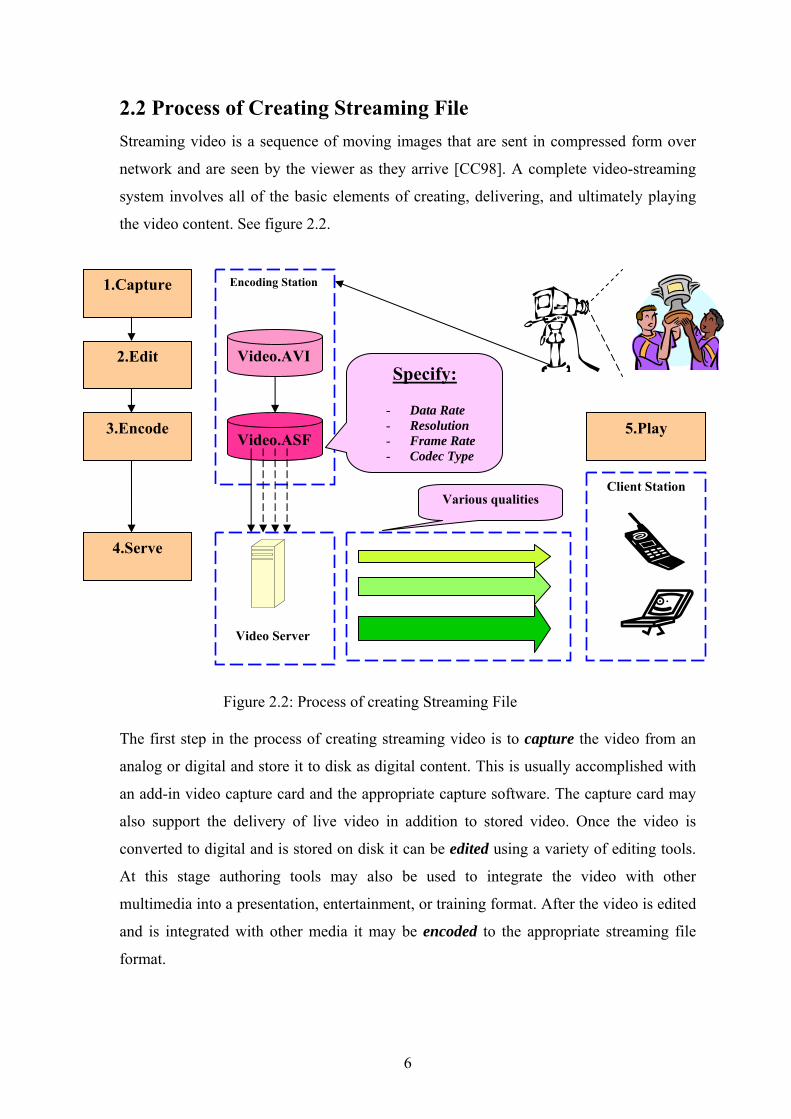
2.2 Process of Creating Streaming File Streaming video is a sequence of moving images that are sent in compressed form over
network and are seen by the viewer as they arrive [CC98]. A complete video-streaming
system involves all of the basic elements of creating, delivering, and ultimately playing
the video content. See figure 2.2.
1.Capture
2.Edit
3.Encode
4.Serve
Encoding Station
Video Server
Client Station
Video.AVI
Video.ASF
Specify:
- Data Rate - Resolution - Frame Rate - Codec Type
Various qualities
5.Play
Figure 2.2: Process of creating Streaming File
The first step in the process of creating streaming video is to capture the video from an
analog or digital and store it to disk as digital content. This is usually accomplished with
an add-in video capture card and the appropriate capture software. The capture card may
also support the delivery of live video in addition to stored video. Once the video is
converted to digital and is stored on disk it can be edited using a variety of editing tools.
At this stage authoring tools may also be used to integrate the video with other
multimedia into a presentation, entertainment, or training format. After the video is edited
and is integrated with other media it may be encoded to the appropriate streaming file
format.
6

This generally involves using the encoding software from the video-streaming vendor and
specifying the desired output resolution, frame rate, and data rate for the streaming video
file. When multiple data rates need to be supported, multiple files may be produced
corresponding to each data rate. As an alternative, newer video streaming technologies
create one file that has dynamic bandwidth adjustment to the needed client data rate. The
video server manages the delivery of video to clients using the appropriate network
transport protocols over the network connection. The video server consists of a hardware
platform that has been optimally configured for the delivery of real-time video plus video
server software that runs under an operating system. Video server software is generally
licensed by the number of streams. If more streams are requested than the server is
licensed for, the software rejects the request. Finally, at the client station the video player
receives and buffers the video stream and plays it in the appropriate size window. The
player generally supports such functions as play, pause, stop, rewind, seek, and fast
forward.
2.3 Streaming Media Delivery Methods There are three main ways that users access and experience media clips.
• On-demand, as with renting a video at a 24-hour video store, a clip is available to
a given user whenever he wants it. This type of clip is pre-recorded or
preassembled. Pre-recorded clips are delivered, or streamed, to users upon request.
A user who clicks a link to an on-demand clip watches the clip from the
beginning. The user can fast-forward, rewind, or pause the clip, and server will
send the right part of it.
• Live, as a live broadcasting of TV programs or radio channels, a user can tune in
to the action that is happening at any given time. Note that a user can not fast-
forward or rewind through the clip, because the event is happening in real time.
• Simulated live, just as television broadcasts sometimes record live events and then
broadcast them later, such as Olympic sports that wouldn't be seen live
everywhere because of time-zone differences, simulated live broadcasts take pre-
recorded events and broadcast them as live ones. Thus, although the content is
pre-recorded, users view the events as if they were live.
7
There are three ways to deliver the clip.
• Unicasting: This is the simplest and most popular method of live broadcasting, as
it requires little or no configuration.
• Splitting: Splitting is the term used to describe how one MediaServer can share its
live media streams with other MediaServers. Clients connect to these other
RealServers, called splitters, rather than to the main MediaServer where the
streams originate. Splitting reduces the traffic load on the source MediaServer,
enabling it to distribute other broadcasts simultaneously.
• Multicasting: Multicasting is a standardized method for delivering presentations
to large numbers of users over the Internet.
2.4 Summary Streaming as a process of playing sound and video content is a very progressive solution.
First, it better utilizes a network capacity. This is the reason of continuous sending of the
negotiated amounts of data. In comparison, downloading load the network capacity as
much as possible. Secondly, streaming by its native facility, allows user to hear and see
content while it is being downloaded. This undoubtedly reduces the time consumed with
downloading of files. Other important advantages are live TV and Radio broadcasting.
Customers are allowed to watch their favourite program from around the world.
8
Chapter 3 Quality of Service
The usability or the success of continuous multimedia application depends largely on the
Quality of Service (QoS) they provide to the end users. As discussed in detail later, the
quality requirements of real-time streaming applications are crucial. Delayed data
transfer, even if delayed only fractionally, makes two-way communication intolerable.
Loss of signals is also instantaneously recognized by human perception. Thus, the QoS
necessary for multimedia applications is an important issue for their usability and success.
3.1 QoS - Quality of Service QoS is currently one of the most elusive and confusing topics in the area of data
networking. One reason surely comes from the expression itself. Words quality and
service are fairly vague and ambiguous. Another reason might be that QoS has different
meanings in different contexts or to different people. It is important to understand the
different meanings. To some, QoS means introducing an element of predictability and
consistency into existing best-effort networks. To others, it means obtaining higher
transport efficiency or throughput from the network. And yet to others, QoS is simply a
means of differentiating classes of data service. It may also mean to match the allocation
of network resources to the characteristics of specific data flows. To examine the concept
of QoS in detail, its two operative words, quality and service, are first examined.
Quality in networking is commonly used to describe the process of delivering data in a
certain manner, sometimes reliable or simply better than normal. It includes the aspect of
data loss, minimal delay or latency and delay variations. Determining the most efficient
use of network resources, such as the shortest distance or the minimal congested route, is
also an issue expressed by quality.
9
The term service has several meanings. It is generally used to describe something offered
to end-users of a network. Services can provide a wide range of offerings, from
application level services, such as Email, WWW, etc., to network or link level services.
The composition of the terms quality and service in the context of networking, puts
definition: network QoS is a measurement of how well the network operates and a means
to define the characteristics of specific network services.
Accordingly, the ISO standard defines QoS as a concept for specifying how “good” a
networking service is. Therefore, QoS provides the means to evaluate services. For
example, Internet Service Providers (ISP) provides more or less the same service, except
that they usually provide different quality.
3.2 QoS Parameters QoS parameters provide a means of specifying user requirements that may or may not be
supported by underlying networks. QoS can only be guaranteed at higher layers if the
underlying layers are also able to guarantee this QoS. The QoS values are usually agreed
between the service provider and the customer at the time the customer subscribes to a
particular service.
QoS parameters also form a basis for charging customers for pre-specified services. With
the increasing interest in continuous media streaming applications such as audio and
video, QoS is becoming more and more important. There are several aspects of QoS to be
considered. For example, to support video communication high throughput is required
and therefore, high bandwidth guarantees will have to be made. Audio communication, in
contrast, does not usually require high bandwidth. End-to-end delay and delay variations
are other factors that must be taken into account for time-critical traffic. In particular,
interactive or real-time media streaming communication imposes stringent delay
constraints, derived from human perceptual thresholds, which must not be violated. Jitter
must also be kept within rigorous bounds to preserve the understand ability of audio and
voice information.
10

A set of QoS parameters suitable for characterizing the quality of service of individual
connections or data flows is as follows:
Delay
End-to-end transit delay is the elapsed time for a packet to be passed from the
sender through the network to the receiver. The higher the delay between the
sender and receiver, the more insensitive the feedback loop becomes. For
interactive or real-time applications the introduction of delay causes the system
to appear unresponsive and as a result in many cases unusable.
Jitter
The variation in end-to-end transit delay is called jitter, also often referred to as
delay variation. In packet-switched networks jitter defines the distortion of the
inter-packet arrival times compared to the inter-packet times of the packet
transmission. High levels of jitter are unacceptable in situations where the
application is real-time. In such cases the distorted data can only be rectified by
increasing the receiver’s reassembly buffer, which effects the end-to-end delay,
making interactive sessions very ponderous to maintain. The strong
interconnection between the end-to-end delay and the jitter should be noted. The
jitter in the network has a direct impact on the minimum end-to-end delay that
can be guaranteed by the network.
Bandwidth
The maximal data transfer rate that can be sustained between two end points of
the network is defined as the bandwidth of the network link. It should be noted
that the bandwidth is not only limited by the physical infrastructure of the traffic
path within the transit networks, which provides an upper bound to the available
bandwidth, but is also limited by the number of other flows sharing common
resources on this end-to-end path. The term bandwidth is used as an upper
bound of the data transfer rate, whereas the expression throughput is used as an
instant measurement of the actual exchanged data rate between two entities.
11

Network applications, for example, have a certain bandwidth disposable
between two nodes, but the amount of data they really transmit is determined by
their throughput. The data throughput of an application is usually highly
dynamic, depending on its needs.
0 ≤ Throughput ≤ Bandwidth
Reliability
This property of the transmission system determines the average error rate of the
transit network. The error rate can be subdivided into bit error rate and packet
or cell error rate. Transport level mechanisms are required to detect and correct
reordered packets.
The QoS requirements should be negotiated at the time of connection or data flow
establishment. Preferred, acceptable and unacceptable tolerance levels for each of these
QoS parameters should be quantified and expressed. The finally agreed QoS should then
be guaranteed for the duration of the transmission.
3.3 Causes of Delay
The one-way, end-to-end delay is the accumulated delay through the entire data flow
including sender coding and packetization, network transmission, reception and decoding.
Some delays, such as coding and decoding, are of fixed duration while others are
nondeterministic due to highly dynamic network or process scheduling conditions. The
minimum end-to-end delay encompasses all time lags which remain constant for all
transmitted units. The maximum end-to-end delay is determined by the sum of the
minimum delay and the maximum jitter. The transmission delay of packets in the network
results from the accumulation of the processing times in every intermediate router (or
switch) between the source and the destination node and the transmission time on the
physical links on this path. The transmission time on the network link is dependent on the
physical medium and the link layer protocol. This is called a propagation delay.
The processing time within the network nodes depends mainly on the forwarding
mechanism in use. Switches or routers that process the packet in hardware require very
little processing time. Such devices are usually found in the core of the network where
many links are concentrated. This is called a processing delay.
12

The processing time of the encoding and packetization at the sender, and the reception
and decoding at the receiver depend mainly on the performance of the processors and the
encoding and decoding algorithm. Some encoding formats require very little computation
whereas others require significant processing power. Even though the processing time
within end hosts is mainly fixed due the constant processing task.
3.4 Causes of Jitter
Packet queuing in the network nodes to compensate traffic bursts is widely recognized to
be the main cause for delay variations. If all the packets of a flow travelling along the
same path encounter the same queue lengths, they all experience the same transit delay.
The end-to-end delay might be high, but the delay variance is zero. Thus, jitter is caused
when consecutive packets experience different waiting times in queues.
Queues grow in a switch or router whenever the sum of the incoming data rates for one
outgoing link is larger than the bandwidth of this outgoing link. In cases where bursty
traffic competes for the available link bandwidth another noteworthy effect called packet
clustering occurs. Figure 3.1 illustrates how these packet clusters develop. At all
subsequent hops these packets arrive closely together and the same might happen again.
Thus, it is likely that clusters grow with the number of hops along a transmission path.
Competing Traffic
Growing Queues
Packet Clustering
Figure 3.1: Packet Clustering
13
Bursty flows competing for bandwidth on a network link and build up queues on the
router’s outgoing interface. Thus several packets of the same flow might arrive while the
first packet is still queuing. Packets of such packet clusters are then sent out very shortly
after one another. The impact of the length of the path on the end-to-end delay variation is
difficult to predict. Under most circumstances the maximum delay variation increases
linearly with the number of hops in the path. In order to fix the delay variation problems
caused by queuing mechanisms in the network, delay sensitive applications need to
deploy services which enable the total time spent in the queues to be limited. Resource
reservation mechanisms such as RSVP for example, are capable of negotiating the
maximum end-to-end delay. Nothing can be done about the transmission path length.
3.5 Causes of Packet Loss Packet switched networks are often unreliable in nature. In particular, significant parts of
the Internet suffer greatly from erroneous data transmission, especially loss of packets.
Packets are frequently discarded due to queue overflows in routers or end-user machines.
As a result, the packet loss rate is an important QoS property for multimedia application.
When packets carrying video data are lost, the video application cannot update the frames
adequately. The image may become inconsistent (for example, moving objects appearing
twice) or may change abruptly upon arrival of the consecutive packets. However, in audio
applications, packet loss leads to crackles and gaps in the audio signal which makes
speech difficult to understand and music less enjoyable. The human eye is known to act
as an integrator of visual information whereas the ear acts as a differentiator. Another fact
is that visual data carries in general more implicit redundancy than audio signals. Thus I
conclude that packet loss within audio streaming is more disturbing for human listeners
than erroneous video transmission. Whereas some packets are lost during the transmission
from the source to the destination, most lost packets are consciously discarded for several
reasons:
First, packets are most frequently dropped because of congestion within the network. If a
network node runs out of buffer space or, in other words, the packet queues overflow,
packets must be discarded. A router usually has incoming buffers, system buffers and
outgoing interface buffers. If packets are dropped due to an incoming queue overflow, it
is called an input drops. Such input drops occur when the router cannot process packets
fast enough. Packet loss due to input drops should not normally appear, since it is the
14

result of a badly engineered system. Output drops, in contrast, occur when the outgoing
link is too busy. This clearly is not a design problem of the router but an issue of available
network bandwidth on the link.
Second, routers use packet dropping as a mechanism to avoid congestion in the network
and prevent queues from reaching their maximum limits. One such technique is known as
Random Early Detection (RED) mechanism. By dropping packets before the queues hit
their maximum limits, sophisticated transport protocols such as TCP can early detect
potential congestion and, as a result, reduce the data rate. UDP does not back off its
transmission rate when congestion occurs. Note that it is also impossible for UDP to
deploy transmission control mechanisms due to the lack of feedback information.
And last, damaged packets as a result of erroneous data transmission are discarded. Bit
errors are usually recognized due to the checksum provided within the packet header;
these checks are often done on multiple levels (for example, the Ethernet link layer and
TCP/UDP transport layer). Reliable protocols like the Ethernet link layer protocol or the
TCP transport layer protocol initiate retransmission of damaged packets, whereas
unreliable protocols such as UDP simply drop the packets. Packets dropped due to bit
errors, however, become less common in today’s fibre networks. Within wireless
networks, in contrast, bit errors are frequent.
3.6 Dynamic QoS Control Because of the increasing demand on QoS requirements, current and future
communication architectures must be extended to support dynamic QoS selections so that
customers are able to precisely tailor individual transport connections to their particular
requirements. Specified QoS levels do not often remain valid for the lifetime of the
transmission. Hence, dynamic QoS control which allows users to alter the QoS of a
connection or data flow during the session is preferential.
State-of-the-art multimedia applications make use of dynamic QoS control mechanisms to
dynamically negotiate their instantaneous QoS demands. The benefits of dynamic QoS
control mechanisms are mainly flexibility and cost reduction. First, the application can
change its QoS level whenever this is desired rather than having to stick to the initial
negotiation. Second, if lower QoS is required, service costs can be reduced by simply
degrading the QoS level.
15
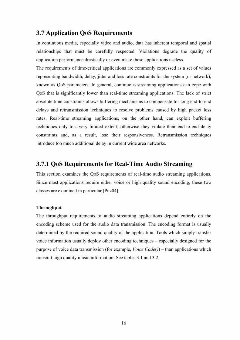
3.7 Application QoS Requirements In continuous media, especially video and audio, data has inherent temporal and spatial
relationships that must be carefully respected. Violations degrade the quality of
application performance drastically or even make these applications useless.
The requirements of time-critical applications are commonly expressed as a set of values
representing bandwidth, delay, jitter and loss rate constraints for the system (or network),
known as QoS parameters. In general, continuous streaming applications can cope with
QoS that is significantly lower than real-time streaming applications. The lack of strict
absolute time constraints allows buffering mechanisms to compensate for long end-to-end
delays and retransmission techniques to resolve problems caused by high packet loss
rates. Real-time streaming applications, on the other hand, can exploit buffering
techniques only to a very limited extent; otherwise they violate their end-to-end delay
constraints and, as a result, lose their responsiveness. Retransmission techniques
introduce too much additional delay in current wide area networks.
3.7.1 QoS Requirements for Real-Time Audio Streaming This section examines the QoS requirements of real-time audio streaming applications.
Since most applications require either voice or high quality sound encoding, these two
classes are examined in particular [Puz04].
Throughput
The throughput requirements of audio streaming applications depend entirely on the
encoding scheme used for the audio data transmission. The encoding format is usually
determined by the required sound quality of the application. Tools which simply transfer
voice information usually deploy other encoding techniques – especially designed for the
purpose of voice data transmission (for example, Voice Coder)) – than applications which
transmit high quality music information. See tables 3.1 and 3.2.
16

Voice Quality Encoding Technique Bit Rate
Telephone Quality Telephone Quality (Lower) Telephone Quality Lower Telephone Quality GSM Phone Quality Low-bandwidth Voice
PCM 64 kbps 32 kbps
40,32,24,16 kbps 16 kbps 13 kbps 8 kbps
DPCM ADPCM
LD-CELP GSM
CS-CELP
Table 3.1: Voice Quality Encoding Techniques and Throughputs
CD quality CD quality Near CD quality Near CD quality Improved CD quality
CD-DA (stereo) MPEG Layer-1 (stereo) MPEG Layer-2 (stereo) MPEG Layer-2 (stereo)
MPEG (stereo)
1.4 Mbps 384 kbps
192-248 kbps 128 kbps 768kbps
Sound Quality Encoding Technique Bit Rate
Table 3.2: Sound Quality Encoding Techniques and Throughputs
Delay
The transit delay requirements for the transmission of continuous audio streams are
highly dependent on the multimedia application. In the case of pure live audio data
distribution (un-directional transmission), long delays are usually tolerable. Large
receiver buffers can be deployed to compensate for high delay variations and
irregularities in the network and end systems. This of course is not the case for interactive
applications such as Internet Telephony or live audio conferencing systems. Interactivity,
especially human conversation, demands high responsiveness. The two-way or round-trip
delay of the streaming application is crucial.
The impression of real-time, which users experience from responsive applications, is
subjective. User studies for the ITU indicate that most telephony users perceive
communication with round-trip delays greater than approximately 300 ms. However,
depending on the application and user perception, more tolerant users are often satisfied
with delays of 300-800 ms.
17
Jitter
Streaming of live audio is probably the most sensitive media type to delay variations. If
packets carrying the audio information arrive with a wide distribution of transit delays,
the receiving system needs to wait a sufficient time called buffering or playout delay.
Otherwise, a significant number of packets would arrive late. This results in sound quality
that is intolerable. Receiver buffering mechanisms temporarily store incoming packets in
a so called buffer until their playout point. The packets can then be played out smoothly
without gaps in the signal. Buffering mechanisms are also often referred to as delay
compensation. Although delay compensation clearly has advantages, there are two
possible drawbacks of this technique. First, an additional delay is introduced at the
receiver. Second, sufficient buffer memory must be available at the receiving system. The
process of determining the best buffering or playout delay is commonly called Playout
Delay Estimation. It is dictated mainly by the following two parameters:
• The maximum overall delay that the application or the end user can tolerate.
• The buffering capabilities of the receiving system.
Reliability
It is commonly recognized that humans are far more sensitive to erroneous audio
transmission than to defective video transfer. This is due to the different processing of
audio and visual information. Thus, QoS requirements for audio are very strict. The
maximum error rate tolerable within audio communications is highly dependent on the
application, the encoding scheme, and the sensitivity of the individual human user.
Study concludes that no more than 5% of erroneous audio data can be tolerated in human
conversations. Another study discovered that a packet loss rate of 1% is clearly noticeable
as a crackle. Up to 13% of packet loss of voice information still allows words to be
understood, but there are many crackles in the signal. Loss rates of 20% still allow
sentences to be understood. This is due to the redundancy in human language. Non
redundant information like numbers get lost. At 25% packet loss only parts of phrases are
understandable. Higher packet loss rates make audio voice transmissions for most people
totally useless. Packet losses within real-time audio streaming cannot simply be resolved
by means of retransmission, since the end-to-end delay constraints would be greatly
exceeded.
18

3.7.2 QoS Requirements for Real-Time Video Streaming
This section introduces the QoS requirements for live video streaming applications. The
aim is to highlight the main differences between audio and video in the context of real-
time media streaming. The following classes of video quality are examined:
Broadcast Quality TV: There are currently two standards, either NTSC, which specifies a
frame rate of 30 fps and a vertical resolution of 525 lines, or PAL/SECAM, which defines
25 fps and 625 lines.
Video Conferencing: Low-bandwidth video conferencing operates at about 128 kbps.
The H.261 compression standard has been developed to support video telephony. This
encoding scheme is particularly suitable for video sequences with little movement (for
example, head and shoulder video conferencing). Moving pictures can be encoded at rates
of p× 64 kbps, where p is in the range 1 to 30.
The picture scanning format Common Intermediate Format (CIF), defined in relation to
H.261, specifies a resolution of 352 pixels per line and 288 lines per frame. To achieve
data rates with less than 128 kbps, the frame rate is limited to 5-10 fps. H.263 is intended
for very low bit-rates >22.8 kbps).
Animated Images: A film of single compressed Images (usually GIF or JPEG encoded) is
transmitted. The quality of the video depends on the size and colours of the single images
and on the available bandwidth on the network path.
Throughput
Compressed broadcast quality TV requires as little as 6 Mbps. Existing implementations
of the MPEG-2 compression standard operate at this rate. It is expected to reduce the bit
rate to 3-4 Mbps for quality equivalent to that of NTSC (PAL/SECAM) broadcast.
Compression schemes such as MPEG-1 or DVI (Digital Video Interactive) provide off-
line compression to 1.2 Mbps for quality similar to VCR quality. The bit rate of 128 kbps,
required for CIF encoded video conferencing quality, is specifically designed for low-
bandwidth links. Work is underway by the MPEG group to define schemes that can
provide video conferencing quality with as little as 32 kbps or even 4.8 kbps within the
new MPEG-4 standard.
19
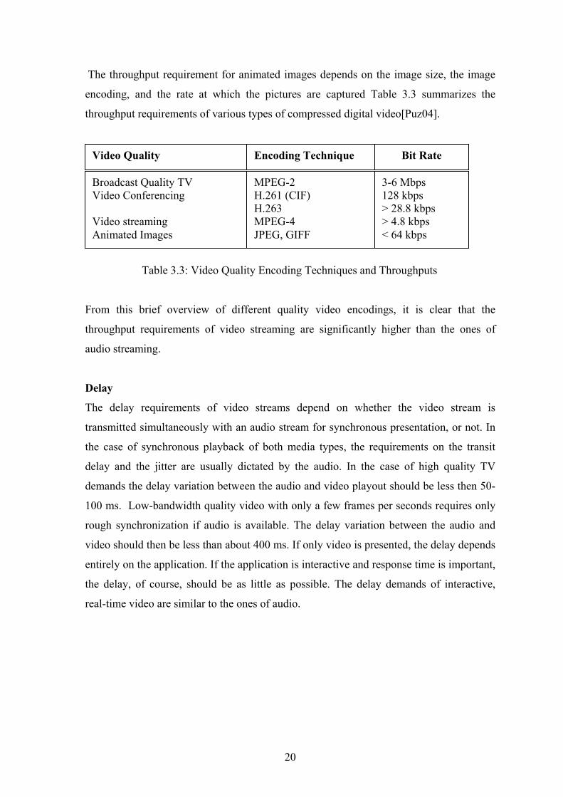
The throughput requirement for animated images depends on the image size, the image
encoding, and the rate at which the pictures are captured Table 3.3 summarizes the
throughput requirements of various types of compressed digital video[Puz04].
Broadcast Quality TV Video Conferencing Video streaming Animated Images
MPEG-2 H.261 (CIF) H.263 MPEG-4 JPEG, GIFF
3-6 Mbps 128 kbps > 28.8 kbps > 4.8 kbps < 64 kbps
Encoding Technique Bit Rate Video Quality
Table 3.3: Video Quality Encoding Techniques and Throughputs
From this brief overview of different quality video encodings, it is clear that the
throughput requirements of video streaming are significantly higher than the ones of
audio streaming.
Delay
The delay requirements of video streams depend on whether the video stream is
transmitted simultaneously with an audio stream for synchronous presentation, or not. In
the case of synchronous playback of both media types, the requirements on the transit
delay and the jitter are usually dictated by the audio. In the case of high quality TV
demands the delay variation between the audio and video playout should be less then 50-
100 ms. Low-bandwidth quality video with only a few frames per seconds requires only
rough synchronization if audio is available. The delay variation between the audio and
video should then be less than about 400 ms. If only video is presented, the delay depends
entirely on the application. If the application is interactive and response time is important,
the delay, of course, should be as little as possible. The delay demands of interactive,
real-time video are similar to the ones of audio.
20

Jitter
As long as the video and audio is synchronized, the jitter requirements of the video
transmission are dictated by the audio. Otherwise, small or moderate delay variations are
still tolerable. While in the case of audio streaming small delay variations result
immediately in spurious sound quality, playout delays of video frames are less disturbing.
This is due to the fact that human sound recognition is more sensitive to irregularities in
the signal than the eye.
The amount of tolerable jitter mainly depends on the video quality and in particular the
frame rate. In the case of high quality video with frame rates of 25-30 fps, jitter above 50
ms will be recognized in most cases. On the other hand, if low-bandwidth video quality
with 5-10 fps is used, jitter of about 100 ms will hardly disturb the user. If
synchronization is required, the playout delay estimations of the audio and video must be
adjusted. The playout point of the video should not vary from the audio by more than 50-
100 ms.
Reliability
As mentioned earlier, humans are less sensitive to erroneous video transmission than to
defective audio transfer. The reason is simply the different processing of audio and visual
information. Therefore, the QoS requirements for video with respect to error liability are
less strict than for audio.
The maximum error rate tolerable within video streaming is highly dependent on the
application. Missing frames usually result in jerky movement. The degree of disturbance
depends on the video quality level and especially the frame rate. Motion interruption in
high quality video is immediately recognized, whereas in low-bandwidth video a missing
frame might not be noticed.
Unlike the case of audio playback, a missing frame does not lead to a gap in the signal.
The user still perceives an image, even if it is an old image. It is only the motion which is
intermittent, whereas in the case of audio playback the signal is completely missing for a
period of time. Since the human eye acts as an integrator of visual information rather than
as a differentiator like the ear, gaps in the signal are not as noticeable. Thus, erroneous
video transmission and in particular packet loss is more tolerable than defective audio
transfer
21

3.8 Summary To guarantee streaming services, QoS and their parameters are undoubtedly necessary.
Thanks to QoS parameters we are able to control application’s requests and ensure
effectivity of network utilization. Interactive audio streaming has very strict end-to-end
QoS requirements, especially with respect to the end-to-end delay, jitter and reliability.
The throughput requirements are less demanding. Video streaming requires significantly
more bandwidth than audio. The end-to-end QoS requirements with respect to jitter and
reliability are less strict than for audio. However, if the video signal is to be synchronized
with the audio, the stronger requirements of audio streaming usually dictate the
transmission characteristics of the video.
22

Chapter 4
Internet Multimedia Protocols This section introduces most of the protocols used in the multimedia streaming
technology. An overview of current protocols is shown in Figure 4.1. It associates the
individual protocols with their OSI layers. Related protocols or protocols with similar
functionalities have the same shading.
Unfortunately in many cases it is hard to classify streaming protocols according to the
OSI reference model. Many modern protocols have a rather vertical design, or in other
words, they cross the boundaries of one layer. An example is RSVP which provides apart
from the network level resource reservation control also an application level interface.
Assigning upper-layer protocols (for example, HTTP, RTSP, etc.) to their OSI reference
model is even more difficult. Hence, the three top layers of the OSI model are merged
into one single layer here called Application Support Layer Protocols. This includes all
protocols above the Transport Layer which provide any kind of service to end-user
applications.
Figure 4.1: Internet Multimedia Protocol Stack
Application Support Layer
Transport Layer
Network Layer
DiffServ IntServ QoS Support
Resource Reservation RSVP
TCP UDP
SDP RTSP HTTP RTP/UDP
RTCP
IPv6 IPv4
23
4.1 Network Layer Protocols
The main network level protocol used within today’s Internet is still IPv4, even though
the next generation Internet protocol IPv6 has already been specified in 1995
[DH95].Since IPv4 specification in 1981 [Pos81]. IPv4 has undoubtedly evolved to be the
most widely deployed network protocol ever.
The Internet protocol is designed for use in interconnected systems of packet-switched
data communication networks. Its function or purpose is to move datagrams through an
interconnected set of networks. This is done by passing the packets from one Internet
module to another until the destination is reached. The selection of the transmission path
and the subsequent forwarding of datagrams along this path is called routing. The packets
are routed from one module to another based on the interpretation of the Internet address
in the datagram. According to the Internet communication model packets are treated as
independent entities and, as far as the network subsystem is concerned, are unrelated to
each other. End-to-end connections have to be emulated at a higher layer (for example,
the transport layer). IPv4 serves as the network layer protocol for the well known
Transport Control Protocol (TCP) and User Datagram Protocol (UDP) that are used
within all of today’s Internet application.
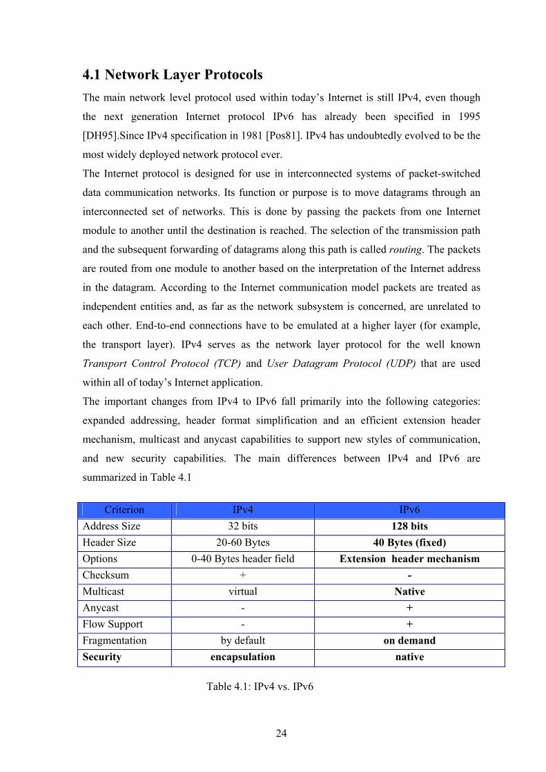
The important changes from IPv4 to IPv6 fall primarily into the following categories:
expanded addressing, header format simplification and an efficient extension header
mechanism, multicast and anycast capabilities to support new styles of communication,
and new security capabilities. The main differences between IPv4 and IPv6 are
summarized in Table 4.1
Criterion IPv4 IPv6
Address Size 32 bits 128 bits Header Size 20-60 Bytes 40 Bytes (fixed) Options 0-40 Bytes header field Extension header mechanism Checksum + - Multicast virtual Native Anycast - + Flow Support - + Fragmentation by default on demand Security encapsulation native Table 4.1: IPv4 vs. IPv6
24
4.2 Transport Layer Protocols
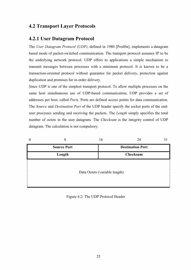
4.2.1 User Datagram Protocol The User Datagram Protocol (UDP), defined in 1980 [Pos80a], implements a datagram
based mode of packet-switched communication. The transport protocol assumes IP to be
the underlying network protocol. UDP offers to applications a simple mechanism to
transmit messages between processes with a minimum protocol. It is known to be a
transaction-oriented protocol without guarantee for packet delivery, protection against
duplication and promises for in-order delivery.
Since UDP is one of the simplest transport protocol. To allow multiple processes on the
same host simultaneous use of UDP-based communication, UDP provides a set of
addresses per host, called Ports. Ports are defined access points for data communication.
The Source and Destination Port of the UDP header specify the socket ports of the end-
user processes sending and receiving the packets. The Length simply specifies the total
number of octets in the user datagram. The Checksum is the integrity control of UDP
datagram. The calculation is not compulsory.
0 8 16 24 31
Source Port Destination Port
Length Checksum
Data Octets (variable length)
Figure 4.2: The UDP Protocol Header
25

4.2.2 Transport Control Protocol The Transmission Control Protocol (TCP) [Pos80b] is known as a reliable host-to-host
protocol between hosts in IP networks. It offers connection-oriented, end-to-end
communication between any pair of hosts connected to the network. It provides reliability
on the top of the unreliable services offered by IP. Interfacing both TCP makes a general
inter-process communication protocol for multi-network environments. Its main design
features are data transfer, reliability, flow control, multiplexing and connections.
In Internet communication TCP has been very successfully used for many years. Most
applications (for example, WWW and Email) and application support layer protocols (for
example, HTTP, FTP, RTSP and SIP) rely on TCP as their transport protocol.
However, experience with TCP has shown that early implementations had some
drawbacks if used in large-scale environments. As a result, most modern implementations
of TCP contain four intertwined algorithms that improve fault tolerance, resource
utilization, efficiency, and scalability. Namely Slow Start Algorithm, Congestion
Avoidance, Fast Retransmission and Fast Recovery.
0 8 16 24 31
Source Port Destination Port
Sequence Number
Acknowledgement Number
DataOffset Reserved Control Bits Window size
Checksum Urgent Pointer
Options
Payload Data (variable length)
Figure 4.3: The TCP Protocol Header
26

4.2.3 Real-time Transport Protocol The Real-time Transport Protocol (RTP) [S+96] provides, according to its specification,
end-to-end delivery services for data with real-time characteristics such as interactive
audio and video. The real-time transport protocol consists of two closely related parts:
• RTP, the real-time transport protocol, adds flow information of the transmitted
real-time media stream to the data packets.
• RTCP, the real-time transport control protocol, provides a feedback channel from
the receiver to the sender. It monitors the QoS of the data stream and conveys the
QoS feedback.
Even though RTP is supposed to be a transport protocol for real-time streaming
applications, it does not provide transport services nor does it guarantees QoS regarding
the bandwidth, delay, jitter, or packet loss. It simply adds a protocol header with stream
information characterizing the media flow (for example, a sequence number, session id
and timestamp) in front of the actual media payload. This information can be used to
compute the QoS that a particular data packet experienced on its transmission path.
0 8 16 24 31
V=2 CSRC Payload Type Sequence Number
Timestamp
Synchronization Source (SSRC) Identifier
Figure 4.4: The RTP Protocol Header
In more detail reviewed, the basic services provided by RTP are payload type
identification, sequence numbering, time stamping and source identification.
The payload type is intended to tell the receiving application how to interpret the payload
data. Based on the payload type, the receiving application selected the appropriate
encoding and compression scheme. The sequence numbers are useful to identify and
process packets that arrive out of order at the receiver node. They facilitate also packet
loss detection. The sender marks each RTP packet with the relative time. The receiver can
use the timestamps to reconstruct the original timing before playing the data stream back.
27

They are probably the most important information provided by the RTP header since it is
means to estimate the delay and jitter. The source identifier can be used, for example, in
audio conferencing applications to indicate the sender currently talking. In multicast
applications with several senders, where all sources send their data to the same multicast
address, source identification becomes necessary in order to associate incoming packets
to the proper data stream.
Applications typically run RTP and RTCP on top of UDP/IP. Figure 4.5 illustrates the
structure of an IP packet containing real-time data that is delivered via RTP/UDP. Since
RTP usually runs on top of UDP/IP, it also supports data transfer to multiple destinations
using multicast distribution.
IP Header UDP Header RTP Header RTP Payload
Figure 4.5: IP packet containing real-time data encapsulated in a UDP and RTP packet
28
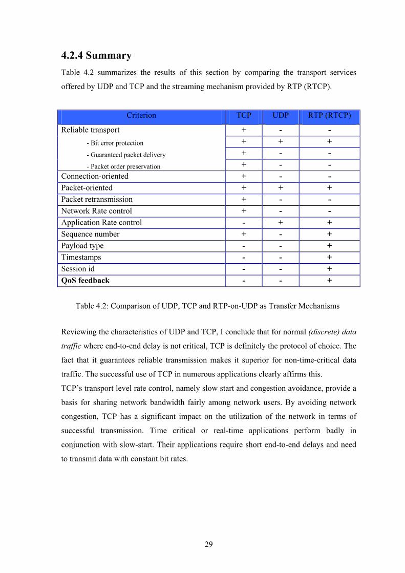
4.2.4 Summary Table 4.2 summarizes the results of this section by comparing the transport services
offered by UDP and TCP and the streaming mechanism provided by RTP (RTCP).
Criterion TCP UDP RTP (RTCP)
+ - - + + + + - -
Reliable transport - Bit error protection
- Guaranteed packet delivery
- Packet order preservation + - - Connection-oriented + - - Packet-oriented + + + Packet retransmission + - - Network Rate control + - - Application Rate control - + + Sequence number + - + Payload type - - + Timestamps - - + Session id - - + QoS feedback - - +
Table 4.2: Comparison of UDP, TCP and RTP-on-UDP as Transfer Mechanisms
Reviewing the characteristics of UDP and TCP, I conclude that for normal (discrete) data
traffic where end-to-end delay is not critical, TCP is definitely the protocol of choice. The
fact that it guarantees reliable transmission makes it superior for non-time-critical data
traffic. The successful use of TCP in numerous applications clearly affirms this.
TCP’s transport level rate control, namely slow start and congestion avoidance, provide a
basis for sharing network bandwidth fairly among network users. By avoiding network
congestion, TCP has a significant impact on the utilization of the network in terms of
successful transmission. Time critical or real-time applications perform badly in
conjunction with slow-start. Their applications require short end-to-end delays and need
to transmit data with constant bit rates.
29

As a result, those applications are better with the simple datagram protocol UDP, as a
transport protocol. Furthermore, the lack of reliable transmission might, in the case of
time critical applications, be a benefit rather than a disadvantage. Even though UDP is
currently the better transport protocol for media streaming, but it has two serious
drawbacks. First, the lack of network-level flow control impedes congestion avoidance.
Nothing prevents applications from permanently congesting the network. Second, UDP
causes many problems if network resources need to be fairly shared among different
protocols and applications. If congestion occurs, for example, TCP backs off whereas
UDP keeps sending with whatever rate the application requires. It means that TCP traffic
is currently suppressed by UDP traffic. Finally, RTP is considered as a streaming
mechanism. Since UDP is used on the transport level, RTP-on-UDP has the same
transport properties. The additional streaming information, namely the timestamp and
session id, can be exploited to compute the instantaneous QoS properties of the delivery
path. This information is especially valuable if adaptation is deployed within the sender
and receiver applications. In order to propagate the QoS feedback to the sender, RTP
includes the control protocol RTCP.
4.3 Reservation Protocols Resource reservation protocols generally communicate application QoS requirements to
the network elements along the transmission path. If the QoS request is admitted by the
network (i.e. bandwidth, processing time, queuing space is at acceptable levels), the
resource reservation is established.
A common misunderstanding is that reservation protocols provide better QoS. Those
signalling protocols simply establish and control reservations. Enforcement of the
reservation must be provided by another component of the QoS architecture. It is similar
to flight reservation systems. The booking system makes sure that a seat is available for
a certain passenger by marking the seat as unavailable for everybody else. However, if
nobody at the airport controls the boarding and checks the flight tickets, the plane might
be full of passengers without reservation. Thus, resource reservation protocols
(signalling) and QoS control services (controlling) complement each other, but are useless
on their own.
30

4.3.1 RSVP The Resource ReSerVation Protocol (RSVP) [B+97] was developed in the University of
California. Today the development of RSVP is carried in the IETF working groups for
RSVP and Integrated Services.
RSVP is intended to be a general resource reservation mechanism used within the
Internet. It is used to establish reservations for network resources on the path from a data
stream source to its destination. The goal of resource reservation is to ensure that the
packets are handled within the network such that they meet the QoS demands of the
communication applications. According to the specification, RSVP provides receiver-
initiated setup of resource reservations.
Each RSVP capable network node requires several modules; see Figure 4.6 as an
illustration. The RSVP daemon handles all protocol messages required to set up and tear
down reservations. RSVP provides a general mechanism for creating and maintaining
distributed reservation state in routers along the transmission path of a flow’s data
packets. If sufficient network resources are available, its requests will result in resources
being reserved in each node along the data path. RSVP only supports reservations for
simplex flows; it requests resources in only one direction. However, nothing prevents an
application process from being a sender and a receiver at the same time.
RSVP Daemon
Policy Control
Admission Control
Application
RSVP capable IntServ node End node
Data Path Packet Scheduler
Packet Classifier
Figure 4.6: Interaction between modules on a RSVP capable node or end host
31

During the reservation setup phase an arriving QoS request (in an RESV message) must
pass two local decision modules, namely the admission control that is part of traffic
control, and the policy control. Admission control checks out whether the node has
sufficient resources available to provide the requested QoS. Policy control, on the other
hand, determines whether the user has the expected administrative permission to make the
reservation. If both subsystems decide to accept the reservation request, the reservation
properties are set in the packet classifier and in the packet scheduler to obtain the desired
QoS. In order to continue the end-to-end reservation establishment along the transmission
path, the RESV message is forwarded upstream towards the sender. If the request is
rejected, the RSVP daemon returns a reservation error message (RESVERR) to the
application which originated the request. When sufficient resources are available, the
RESV message will finally arrive at the sender node indicating that the reservation has
been successfully established.
Since reservations in RSVP are receiver-initiated, RSVP must make sure that the
reservation messages (RESV) follow exactly the reverse route to the data flow. This
reverse path (or tree in the case of multicast) is maintained by periodic path messages
(PATH) initiated by the senders. PATH messages are sent downstream along the routing
path provided by the IP routing protocol. Figure 4.7 illustrates how the PATH and RESV
messages travel between the RSVP nodes assuming a simple network topology.
Figure 4.7: A simple network topology with the data path from the sender (H1) to the
N1
N5
N6
N2
N4
N3
H1
H2
H3
Routing path
Reservation path
receiver (H2 and H3) and the reverse path from the receivers to the sender
32
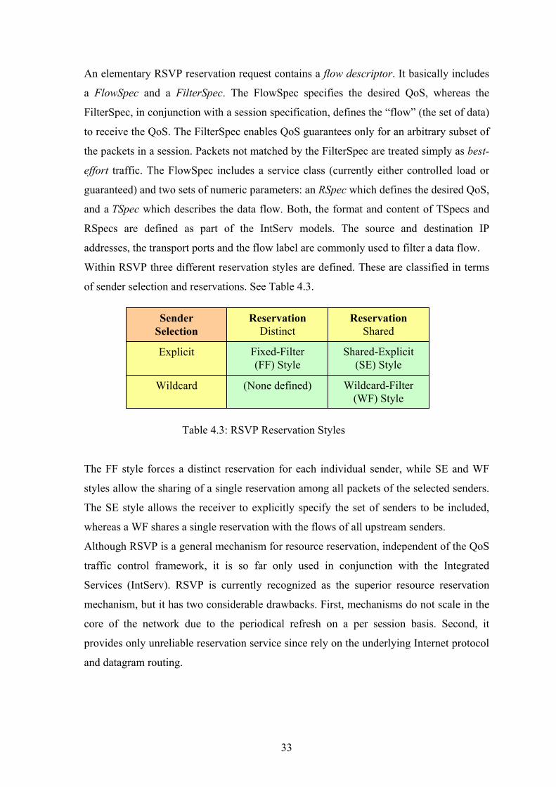
An elementary RSVP reservation request contains a flow descriptor. It basically includes
a FlowSpec and a FilterSpec. The FlowSpec specifies the desired QoS, whereas the
FilterSpec, in conjunction with a session specification, defines the “flow” (the set of data)
to receive the QoS. The FilterSpec enables QoS guarantees only for an arbitrary subset of
the packets in a session. Packets not matched by the FilterSpec are treated simply as best-
effort traffic. The FlowSpec includes a service class (currently either controlled load or
guaranteed) and two sets of numeric parameters: an RSpec which defines the desired QoS,
and a TSpec which describes the data flow. Both, the format and content of TSpecs and
RSpecs are defined as part of the IntServ models. The source and destination IP
addresses, the transport ports and the flow label are commonly used to filter a data flow.
Within RSVP three different reservation styles are defined. These are classified in terms
of sender selection and reservations. See Table 4.3.
Sender Selection
Reservation Distinct
Reservation Shared
Fixed-Filter (FF) Style
(None defined) Wildcard
Explicit
Wildcard-Filter (WF) Style
Shared-Explicit (SE) Style
Table 4.3: RSVP Reservation Styles
The FF style forces a distinct reservation for each individual sender, while SE and WF
styles allow the sharing of a single reservation among all packets of the selected senders.
The SE style allows the receiver to explicitly specify the set of senders to be included,
whereas a WF shares a single reservation with the flows of all upstream senders.
Although RSVP is a general mechanism for resource reservation, independent of the QoS
traffic control framework, it is so far only used in conjunction with the Integrated
Services (IntServ). RSVP is currently recognized as the superior resource reservation
mechanism, but it has two considerable drawbacks. First, mechanisms do not scale in the
core of the network due to the periodical refresh on a per session basis. Second, it
provides only unreliable reservation service since rely on the underlying Internet protocol
and datagram routing.
33

4.4 Application Layer Protocols Among the great number of application layer protocols used in the Internet only the
protocols useful for stream setup and control of real-time media streaming applications
are examined in this section.
4.4.1 Hyper Text Transfer Protocol The Hyper Text Transfer Protocol (HTTP) [BL+96] is a generic, stateless, and object-
oriented application-level protocol that can be used for a variety of tasks based on the
request-response methodology. Since 1990 when the World-Wide Web (WWW) initiative
decided to use HTTP, it has evolved to one of the most widely deployed application level
protocols today. Although it is currently exclusively used on top of the transport protocol
TCP, HTTP is independent of the transport protocol. It merely requires that the
underlying transport protocol provides reliable service.
4.4.2 Real-Time Streaming Protocol The Real Time Streaming Protocol (RTSP) [S+98] is an extensible framework to control
delivery of real-time media data, such as audio and video.
RTSP is designed as a signalling protocol for the establishment and control of one or
more time-synchronized streams of continuous media. A good comparison of RTSP with
a real world device is the VCR remote control. Like a VCR remote control, RTSP can be
used to start, stop, and pause selected media clips. This “Internet remote control” supports
operation to control both, live data feeds or stored media clips. RTSP is often
misunderstood to be a transport protocol. However, it is not involved in the delivery
process of the continuous streams itself.
RTSP itself is independent of any particular transport mechanism. All current Internet
transport mechanisms, namely UDP, TCP, and RTP-on-UDP are supported. The
signalling channel of RTSP is also independent of the transport protocol. Both UDP and
TCP are supported.
34

4.4.3 Summary This section compares the application level protocols HTTP and RTSP and discusses their
usability as stream control protocols.
Difference between HTTP and RTSP is that HTTP is limited to use the reliable transport
protocol TCP whereas RTSP is independent of the transport protocol. RTSP is not tied to
any specific transport protocol. It can deploy UDP for its request-response messages
instead. The main advantage of RTSP over HTTP is that RTSP is a symmetrical protocol.
Thus, the server can also initiate communication. RTSP is clearly the more sophisticated
stream control protocol, and hence, preferable in cases where the whole range of control
functionally is required, simple http based stream control has the advantage that existing
http user agents (such as standard Web browsers) can simply be used as clients. Finally,
RTSP requires a presentation description format which can express both static and
temporal properties of a presentation containing several media streams. The description
format of choice here is the Session Description Protocol (SDP). It is especially designed
to describe multimedia sessions for the purposes of session initiation and control.
4.5 Summary This section concludes the study on Internet multimedia protocols presented throughout
this chapter. The study examines the most important protocols currently used within
Internet multimedia applications and explores their usability within interactive real-time
media streaming.
The network layer protocol IPv6 is compared with its predecessor IPv4. Besides resolving
the address problem, the benefits of the new Internet protocol regarding interactive real-
time streaming can be summarized as follows:
• IPv6 improves the packet processing in every intermediate router due to
simplification of the IP header. This has the potential to decrease the overall
network load and to reduce the end-to-end delay of real-time streaming simply
due to faster packet processing in each intermediate router.
• IPv6 provides native multicast and security support which facilitates media
broadcast and secure data transmission within streaming applications.
• The IPv6 flow label, which introduces the concept of a flow, resolves the
implicit layer violation problem of RSVP and has a great impact on the
performance of packet classification.
35

Although IPv6 has the potential clearly to improve real-time streaming applications, it
does not magically resolve the QoS problems of Internet communication.
The transport protocols and streaming mechanisms discussed are: UDP, TCP and RTP-
on- UDP. Whereas TCP is not suitable for interactive real-time streaming applications
because of the interference of its congestion control and reliability mechanisms with the
requirements of time-critical applications, UDP provides a simple but sufficient service.
RTP-on-UDP is recommended as the streaming mechanism for real-time applications
because it adds valuable stream information to the media packets. RTP’s control protocol
RTCP is especially useful in conjunction with server-site adaptive mechanisms due to the
QoS feedback channel.
The resource reservation protocol RSVP is discussed. Even though RSVP is currently the
resource reservation protocol of choice within the IETF, it has several significant
drawbacks:
• The periodic PATH and RESV messages and per flow PATH and RESV state
within network routers do not scale successfully in the core of the network.
• Due to the lack of acknowledge messages, RSVP has a very slow establishment
time if initial PATH or RESV messages are lost.
• RSVP is not a reliable reservation protocol, since it is dependent on the underlying
routing protocol.
The application level protocols HTTP and RTSP are discussed and evaluated for use in
stream control. RTSP is a sophisticated stream control protocol with similar functionality
to a “VCR remote control”. It provides sufficient control functionality for stream control
and is therefore recommended for use within media streaming applications. Whereas
RTSP based stream control requires special RTSP capable clients, HTTP based stream
control can simply be accomplished by means of standard Web browsers. However, the
lack of session or stream semantics limits its usability. Although HTTP could be extended
in order to provide equivalent functionality to RTSP, it would then lose its main
advantage, namely that stream control can be achieved simply by means of a standard
Web browser.
36

Chapter 5 Real-Time Streaming in the Internet
This chapter discusses application level techniques that are used to compensate for the
lack of network QoS and explores current network level QoS models which aim is
improving the usability of real-time media streaming applications within the Internet.
Current Internet researchers have not yet come to an agreement on how to achieve QoS
for these applications in the network. Some believe that the QoS in the network depends
only on the amount of available bandwidth. Hence, they propose simply to increase the
amount of bandwidth to resolve the QoS problems. Temporary bottlenecks or momentary
service degradations could be overcome by means of adaptation. On the other hand,
others think that the network should rely on resource management mechanisms in order to
guarantee QoS to the user. Resource reservation is one mechanism to achieve guaranteed
service for real-time media streaming applications.
Section 5.1 describes several network level QoS mechanisms that are being currently
discussed. Section 5.2 application level techniques to improve the quality of simple best-
effort based network communication.
5.1 Network Layer QoS This section introduces various different network layer mechanisms to achieve network
level QoS or differentiated QoS classes in the Internet. First, techniques that are
commonly called service differentiation mechanisms are introduced. Second, a network
service that provides QoS guarantees based on resource reservation is explored. This
network service or QoS framework is known as Integrated Services. The third, QoS in
MPLS is shortly indicated.
37
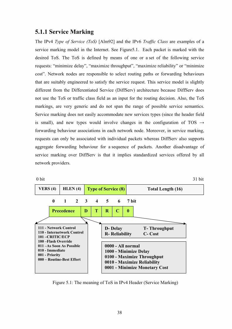
5.1.1 Service Marking The IPv4 Type of Service (ToS) [Alm92] and the IPv6 Traffic Class are examples of a
service marking model in the Internet. See Figure5.1. Each packet is marked with the
desired ToS. The ToS is defined by means of one or a set of the following service
requests: “minimize delay”, “maximize throughput”, “maximize reliability” or “minimize
cost”. Network nodes are responsible to select routing paths or forwarding behaviours
that are suitably engineered to satisfy the service request. This service model is slightly
different from the Differentiated Service (DiffServ) architecture because DiffServ does
not use the ToS or traffic class field as an input for the routing decision. Also, the ToS
markings, are very generic and do not span the range of possible service semantics.
Service marking does not easily accommodate new services types (since the header field
is small), and new types would involve changes in the configuration of TOS →
forwarding behaviour associations in each network node. Moreover, in service marking,
requests can only be associated with individual packets whereas DiffServ also supports
aggregate forwarding behaviour for a sequence of packets. Another disadvantage of
service marking over DiffServ is that it implies standardized services offered by all
network providers.
0 bit 31 bit
VERS (4) HLEN (4) Type of Service (8) Total Length (16)
0 1 2 3 4 5 6 7 bit
111 - Network Control 110 - Internetwork Control 101 –CRITIC/ECP 100 –Flash Override 011 –As Soon As Possible 010 - Immediate 001 - Priority 000 – Routine-Best Effort
Precedence D T C R 0
D- Delay T- Throughput R- Reliability C- Cost
0000 - All normal 1000 - Minimize Delay 0100 - Maximize Throughput 0010 - Maximize Reliability 0001 - Minimize Monetary Cost
Figure 5.1: The meaning of ToS in IPv4 Header (Service Marking)
38

5.1.2 Differentiated Services This architecture achieves scalability by implementing complex classification and
conditioning functions at network boundary nodes, and by applying Per-Hop Behaviours
(PHB) to aggregates of traffic which have been appropriately marked using the DS field in
the IP headers. Within the core of the network packets are forwarded according to the per-
hop behaviour associated with the DS code-point (DSCP). See Figure 5.2. The difference
to other service marking models is mainly that the service classes are not limited to a pre-
defined standard, but are rather flexible. [Nich98].
Forwarding Behaviour
The forwarding behaviour applied to a particular service class of a DS node is
described within the node’s PHB. Per-hop behaviour is defined in terms of
behaviour characteristics relevant to service provisioning policies. PHBs can
be specified by means of their resource priority relative to other PHBs or in
terms of their relative observable traffic characteristics. PHBs are defined to
permit a reasonably granular means of allocating buffer and bandwidth
resources at each node among competing traffic streams.
0 31 bit
VERS (4) HLEN (4) Type of Service (8) Total Length (16)
0 1 2 3 4 5 6 7 bit
Drop Precedence Class 1 Class 2 Class 3 Class 4
Low
Medium
High
AF11 001010
AF 21 010010
AF 31 011010
AF 41 100010
AF 22 010100
AF 32 011100
AF 42 100100
AF 13 001110
AF 23 010110
AF 33 011110
AF 43 100110
AF 12 001100
Assured forwarding PHB
CU DSCP
Expedited forwarding PHB
Default PHB
000000
101110
DSCP – Differentiated Services Code Point CU - Currently Unused
Figure 5.2: The meaning of ToS in IPv4 Header (Differented Services)
39
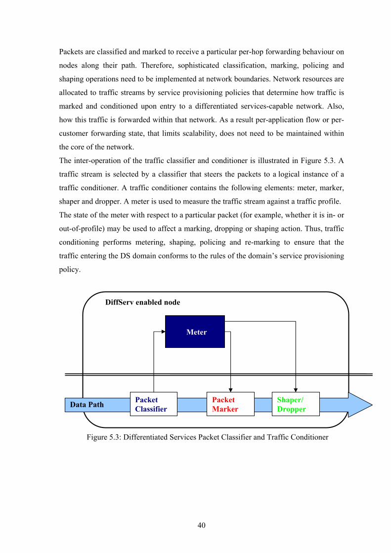
Packets are classified and marked to receive a particular per-hop forwarding behaviour on
nodes along their path. Therefore, sophisticated classification, marking, policing and
shaping operations need to be implemented at network boundaries. Network resources are
allocated to traffic streams by service provisioning policies that determine how traffic is
marked and conditioned upon entry to a differentiated services-capable network. Also,
how this traffic is forwarded within that network. As a result per-application flow or per-
customer forwarding state, that limits scalability, does not need to be maintained within
the core of the network.
The inter-operation of the traffic classifier and conditioner is illustrated in Figure 5.3. A
traffic stream is selected by a classifier that steers the packets to a logical instance of a
traffic conditioner. A traffic conditioner contains the following elements: meter, marker,
shaper and dropper. A meter is used to measure the traffic stream against a traffic profile.
The state of the meter with respect to a particular packet (for example, whether it is in- or
out-of-profile) may be used to affect a marking, dropping or shaping action. Thus, traffic
conditioning performs metering, shaping, policing and re-marking to ensure that the
traffic entering the DS domain conforms to the rules of the domain’s service provisioning
policy.
Meter
Data Path Packet Classifier
Packet Marker
Shaper/ Dropper
DiffServ enabled node
Figure 5.3: Differentiated Services Packet Classifier and Traffic Conditioner
40

Differentiated services are extended across a DS domain boundary by establishing a
Service Level Agreement (SLA). Briefly, the SLA specifies packet classification and re-
marking rules. DiffServ provides a simple QoS framework for the Internet without the
stringent need for changes in end-user applications and end systems. Even if only parts of
the end-to-end transmission path support DiffServ, the service operates well within these
bounds. Unlike end-to-end resource reservation mechanisms such as IntServ/RSVP,
DiffServ does not require that all network nodes along a delivery path support the service.
The DiffServ architecture has the potential to resolve the scalability problem of the
IntServ architecture in the core of the network, since no per-flow state is required within
network elements.
In contrast, end-to-end QoS guarantees, as supported by IntServ, cannot be accomplished.
The fact that DiffServ depends on the resource allocation mechanisms provided by per-
hop behaviour implementations prevents DiffServ from offering end-to-end service
guarantees.
5.1.3 IP Label Switching In IP label switching, path forwarding state or QoS state are established for data streams
on each hop along a network path. Traffic flows are marked with a forwarding label and
associated with the corresponding label-switched path at ingress nodes. Label values are
not globally significant but are only meaningful on a single link. Therefore, resources can
be reserved for the aggregate of packets received on a link with a particular label. IP label
switching is generally a very efficient approach, especially if media streams are long-
lived. In this case, IP label switching is by far more efficient than regular IP routing due
to the simpler decision making process in the network routers. Since label switching can
be processed very efficiently within network nodes, it has the potential to improve delay
sensitive applications by reducing the processing delays in every intermediate node.
An example, the meanings of MPLS Header is shown in figure 5.4.
Figure 5.4: The MPLS Header
IP Header TCP Header Label Exp S TTL Payload
Bits: 0-19 > Label 20-22 > Exp. Bits (Class of Service) 23 > S-flag 24-31 > Time To Live
41
5.1.4 Integrated Services The IETF’s Integrated Services (IntServ) [Wro97] architecture provides network level
QoS by controlling the network delivery service. This enables QoS sensitive applications
to request their QoS desires by means of resource reservation mechanisms.
The Integrated Services framework provides the ability for applications to choose
different controlled levels of delivery service for their data packets. Before sending the
data packets applications use a reservation mechanism to establish the resource
reservation for the data stream. Different levels of QoS guarantees, namely soft and hard
guarantees, are supported within this framework.
In order to support resource reservation within the Internet two entities are required. First,
all network elements (IP routers) along the delivery path of an application’s data flow
must support mechanisms to control and provide the QoS required by packets of the
reserved flow. This is called the QoS control service. Second, a protocol to communicate
the application’s QoS requirements to the individual network elements along the path and
to convey QoS management information between network elements and the application
must be provided. This is referred to as reservation setup mechanism. In the IntServ
architecture the QoS control is provided by either the controlled-load or guaranteed
service. The Resource reSerVation Protocol (RSVP) is currently the mechanism of choice
within the Internet for reservation setup.
Reservation Setup Mechanism
The reservation setup mechanism is responsible for establishing and maintaining the
resource reservation along the transmission path. In order to invoke the QoS control
service within the network elements, several types of data must be exchanged between the
application and those network elements.
First, information generated at the sender, describing the data traffic (the sender TSpec)
of the sender application is carried to intermediate network elements and to the receiver.
Second, information generated or modified within the network elements and required at
the receiver to make reservation decisions, encompass the available services, delay and
bandwidth estimates. The information is collected from network elements and carried
towards receivers in so called AdSpec messages. Rather than carrying information from
each intermediate node separately to the receivers, this information represents a summary,
computed as it passes each individual hop along the transmission path.
42

Third, information generated by each receiver, describes the QoS control service required
for the reservation (guaranteed or controlled load), a description of the traffic level for
which resources should be reserved (the receiver TSpec), and whatever parameters are
required to invoke the service (the receiver RSpec). This information is carried from the
receiver to intermediate network elements, and finally, if the reservations have been
installed successfully, to the sender in so called FlowSpec messages. The FlowSpec
describes the QoS parameters of a data flow, and if the resources are granted, it specifies
the resource reservation. In order to associate a FlowSpec with a particular data flow, a
FilterSpec is required. The FilterSpec specifies the packets that can make use of the
reserved resources (see Figure 5.5)
FilterSpec Sender Port Sender Address
RSpec Rate Slack Term
TSpec Token Bucket Rate Token Bucket Size Peak Data Rate Minimum Policed Unit Maximum Packet Size
FlowSpec Service Model Controlled load or Guarantee Service
Figure 5.5: The IntServ Reservation Request Format: FlowSpec and FilterSpec
QoS control services
Traditionally the Internet provides the same QoS to every data packet. This service is
known as simple best-effort service. The network promises no boundaries on delay, jitter
or loss rate. It simply tries to deliver the packets as soon as possible. In the IntServ
architecture the QoS control is provided by either the controlled-load or guaranteed
service.
Guaranteed Service
Guaranteed service [SPG97] provides firm bounds on end-to-end packet queuing
delays. It offers sufficient service for real-time streaming application with hard
QoS requirements. Guaranteed services make use of resource reservation
mechanisms in order to provide fixed, guaranteed bounds on end-to-end delay and
jitter. Guaranteed service does not explicitly minimize the jitter. It merely controls
the maximum queuing delay and hence provides an upper bound for the jitter. The
concept behind guaranteed service is that a flow is described using a token bucket.
43

Based on this flow description, network elements (routers, subnets, etc.) compute
various parameters describing how the service element will handle the packets of
this flow. By accumulating the parameters of all network elements along a
transmission path, the maximum delay that a packet might experience can be
determined.
Controlled Load Service
Controlled load service [Wro97a] promises a QoS service for data flows that is
closely approximating the QoS that the same flow would receive from an
unloaded network with best-effort service. In contrast to guaranteed service it does
not give explicit or hard QoS guarantees with respect to bandwidth, delay and
jitter. Nonetheless, the service provides low end-to-end delays and very few
packet losses.
Controlled load service is designed for applications that are highly sensitive to
overloaded conditions (for example, live video streaming) but can tolerate small
QoS variations. Applications with fixed end-to-end timing requirements that fail
immediately when end-to-end delays exceed their boundaries require hard QoS
guarantees. Adaptive real-time streaming applications operate badly under
overloaded or congested network conditions. However, network experiments have
shown that they work well on unloaded networks.
The controlled load service is similar to the guaranteed service in that sender
nodes communicate the token bucket specification (TSpec) of their traffic to the
network. The network nodes ensure that enough resources will be set aside for the
data flow. Active admission control mechanisms prevent the network elements
from overloading their link. As in the case of guaranteed service, controlled load
service provides QoS only for traffic conforming to the TSpec given at setup time.
Excess traffic should simply be forwarded on a best-effort basis if sufficient
resources are available.
Controlled load service is advantageous over guaranteed service in that it enables
much better overall network utilization. Note, guaranteed resource reservations
often waste a large percentage of the available resources since they are not always
fully used. Hence, controlled load service offers a more cost-effective solution if
no real hard guarantee is required.
44
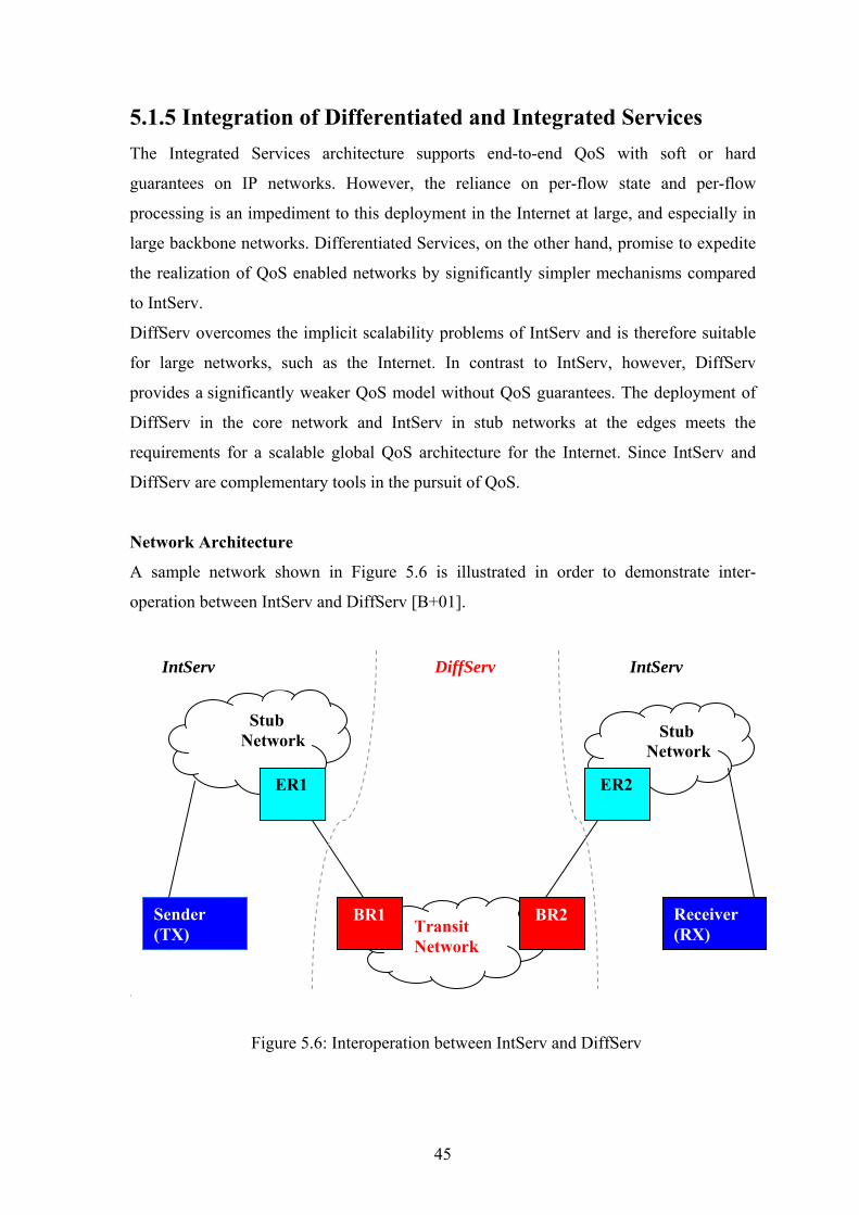
5.1.5 Integration of Differentiated and Integrated Services The Integrated Services architecture supports end-to-end QoS with soft or hard
guarantees on IP networks. However, the reliance on per-flow state and per-flow
processing is an impediment to this deployment in the Internet at large, and especially in
large backbone networks. Differentiated Services, on the other hand, promise to expedite
the realization of QoS enabled networks by significantly simpler mechanisms compared
to IntServ.
DiffServ overcomes the implicit scalability problems of IntServ and is therefore suitable
for large networks, such as the Internet. In contrast to IntServ, however, DiffServ
provides a significantly weaker QoS model without QoS guarantees. The deployment of
DiffServ in the core network and IntServ in stub networks at the edges meets the
requirements for a scalable global QoS architecture for the Internet. Since IntServ and
DiffServ are complementary tools in the pursuit of QoS.
Network Architecture
A sample network shown in Figure 5.6 is illustrated in order to demonstrate inter-
operation between IntServ and DiffServ [B+01].
.
Figure 5.6: Interoperation between IntServ and DiffServ
Transit Network
Stub Network
Stub Network
ER1 ER2
BR1 BR2 Sender (TX)
Receiver (RX)
IntServ DiffServ IntServ
45

The transmitting (TX) and receiving (RX) hosts use a resource setup mechanism, such as
RSVP to communicate the QoS requirements. Both, TX and RX, are part of IntServ stub
networks. The transit network, on the other hand, is not required to be IntServ capable. It
provides DiffServ service based on the DS field in the headers of carried packets. In order
to provide end-to-end QoS services, the transit network must be able to carry messages of
the resource setup mechanism transparently to other stub networks.
The IntServ service types (controlled load and guaranteed service) must be mapped to a
DiffServ service class (or behaviour aggregate) on the boundary routers (BRs). End-to-
end services can be provided by concatenating PHBs. The contract negotiated between
the customer (owner of the stub network) and the carrier (owner of the transit network)
for the capacity to be provided by each of a number of standard DiffServ service classes
is called the carrier-customer agreement. Edge routers (ERs) are special routers that
bridge the IntServ and DiffServ region of the network.
The inter-operation of IntServ and DiffServ to provide a scalable QoS framework for
today’s Internet is successful in that it resolves the scalability problem of IntServ in core
networks. However, the hard end-to-end QoS guarantees that IntServ can offer become
lost by mapping IntServ reservations onto DiffServ service classes. It is important to note
that DiffServ does not offer end-to-end services.
New approaches or approaches that incorporate the IntServ and DiffServ architectures are
more likely to become the future QoS framework within the Internet. Since many believe
that the future QoS solution for the Internet includes the ideas of DiffServ and the
IntServ, industry leading companies investigate both approaches.
5.1.6 Summary This section summarizes the study of network layer QoS mechanisms that are currently of
interest within Internet. The first group of mechanisms includes various service
differentiation mechanisms, namely service marking, and DiffServ.
Service marking enhances service differentiation based on relative priorities by increasing
the range of possible service semantics. However, service marking has no provision to
easily add new service types since the header field is small and new types would involve
changes in each network node. Unlike DiffServ, service marking uses the marking also as
an input for the routing decision. It outperforms the two former differentiation
mechanisms by supporting flexible service classes that are not limited to a pre-defined
46
standard. In principle, DiffServ provides a mechanism that divides the network into
several virtual best-effort networks each of that offers different QoS. Since DiffServ does
not require per-flow state information within network routers, it has the potential to
resolve the scalability problem of IntServ in the core of the network. However,
forwarding behaviours only on a per-hop basis prevent DiffServ from offering end-to-end
service guarantees. Moreover, the lack of a reliable admission control mechanism
impedes DiffServ from offering reliable resource promises. Even though DiffServ cannot
guarantee end-to-end QoS, it has the potential to improve network QoS received by real-
time streaming application when widely deployed in the Internet. QoS sensitive real-time
media traffic would then be protected from discrete data traffic.
The IntServ architecture provides network level QoS by controlling the network delivery
service. Real-time streaming applications can request their QoS demands by means of a
resource reservation protocol. Granted QoS provides optimal service for QoS sensitive
applications such as real-time streaming applications. IntServ supports guaranteed (hard)
and controlled load (soft) QoS guarantees. On the one hand, controlled load QoS,
providing service equivalent to unloaded networks, is suitable for adaptive real-time
streaming applications that are capable of dealing with small variations in the QoS. On
the other hand, guaranteed QoS, offering hard QoS guarantees, provides optimal service
for real-time streaming applications even without adaptation, error correction, and
receiver buffering mechanisms. The main drawbacks of IntServ can by summarized as
follows: first, IntServ relies on all network elements along a transmission path to support
end-to-end reservations, and second, per-flow state is required in every intermediate
network element. This, of course, does not scale in large networks and in particular not
within the core of the Internet. Another approach that integrates IntServ and DiffServ
suggests to use DiffServ as a scalable, hop-by-hop QoS mechanism in the core of the
network, and IntServ at the stub networks, where scalability is not a problem. In the
DiffServ network in the core, IntServ QoS reservations must be mapped to appropriate
DiffServ service classes.
47

5.2 Application Layer QoS This section describes application level mechanisms that are worth considering when
developing real-time streaming applications. These techniques are designed to achieve
higher quality application services to increase end-user satisfaction.
5.2.1 Adaptation Media streaming applications must tolerate variations in QoS (i.e. dynamic changes of
delay variations, preserved throughput and packet loss) delivered by the network.
Mechanisms to provide continuous service even when external conditions change (i.e.
network congestion, router queue overflows and processing overload) are commonly
known as QoS adaptation mechanisms. Adaptive applications are able to gracefully adapt
their service quality depending on the QoS received from lower level services.
Application level QoS adaptation is increasing or reducing the QoS properties of the
application depending on variations in the network QoS characteristics. Adaptation, for
example, changes the media stream (i.e. quality, encoding format), adds redundancy to
the stream, or adjusts the receiver buffer size to make users think that their application
have constant network service qualities. If the QoS degrades below the adaptation limits,
adaptation cannot operate properly anymore and the quality remains poor. If the network
supports QoS by means of resource reservation, applications have guaranteed resources
for their media stream, and hence, need not adapt to changing network QoS
characteristics. Thus, in an environment where resource reservation is available,
adaptation is only of user-initiated nature.
In summary I conclude that adaptive applications significantly improve performance
under moderate to high network load. However, they can only account service
degradation to a certain level.
48
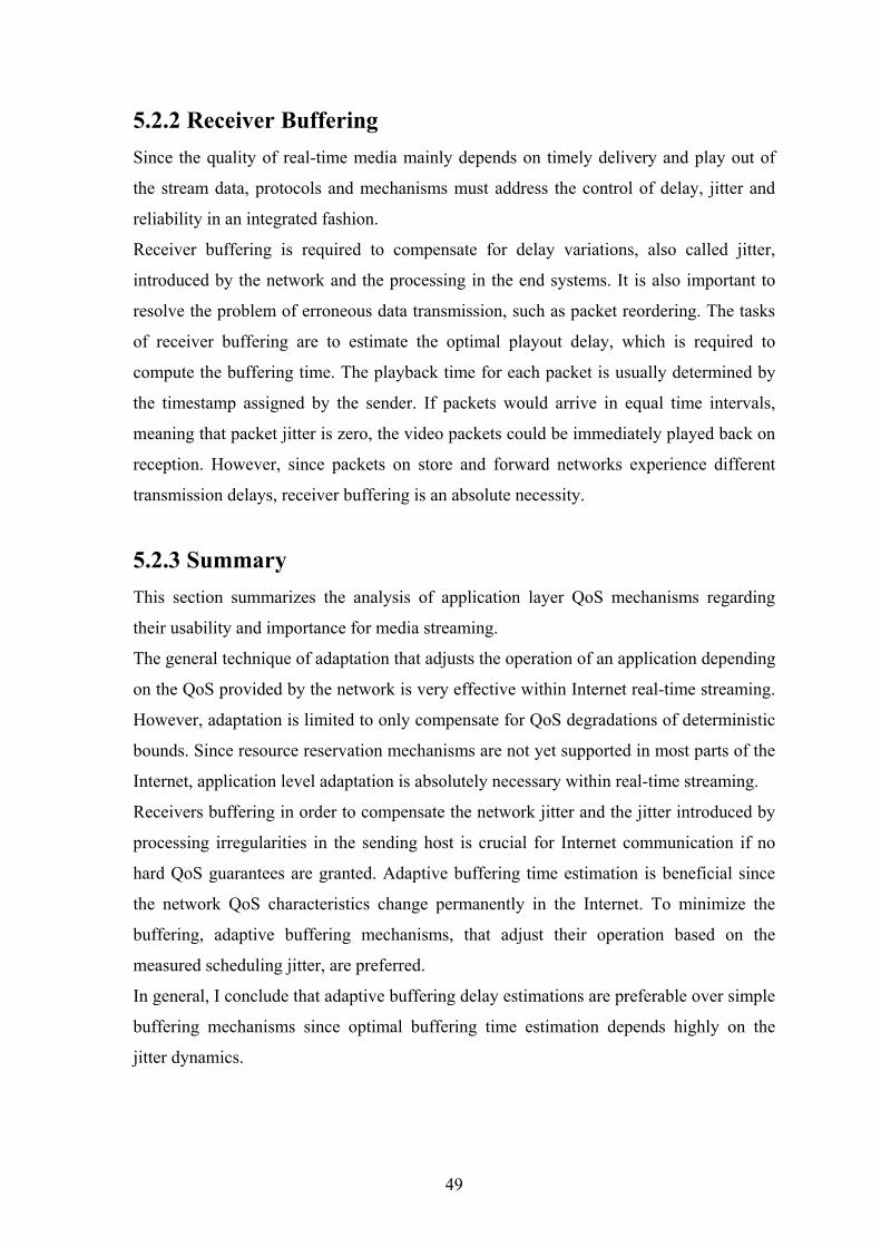
5.2.2 Receiver Buffering Since the quality of real-time media mainly depends on timely delivery and play out of
the stream data, protocols and mechanisms must address the control of delay, jitter and
reliability in an integrated fashion.
Receiver buffering is required to compensate for delay variations, also called jitter,
introduced by the network and the processing in the end systems. It is also important to
resolve the problem of erroneous data transmission, such as packet reordering. The tasks
of receiver buffering are to estimate the optimal playout delay, which is required to
compute the buffering time. The playback time for each packet is usually determined by
the timestamp assigned by the sender. If packets would arrive in equal time intervals,
meaning that packet jitter is zero, the video packets could be immediately played back on
reception. However, since packets on store and forward networks experience different
transmission delays, receiver buffering is an absolute necessity.
5.2.3 Summary This section summarizes the analysis of application layer QoS mechanisms regarding
their usability and importance for media streaming.
The general technique of adaptation that adjusts the operation of an application depending
on the QoS provided by the network is very effective within Internet real-time streaming.
However, adaptation is limited to only compensate for QoS degradations of deterministic
bounds. Since resource reservation mechanisms are not yet supported in most parts of the
Internet, application level adaptation is absolutely necessary within real-time streaming.
Receivers buffering in order to compensate the network jitter and the jitter introduced by
processing irregularities in the sending host is crucial for Internet communication if no
hard QoS guarantees are granted. Adaptive buffering time estimation is beneficial since
the network QoS characteristics change permanently in the Internet. To minimize the
buffering, adaptive buffering mechanisms, that adjust their operation based on the
measured scheduling jitter, are preferred.
In general, I conclude that adaptive buffering delay estimations are preferable over simple
buffering mechanisms since optimal buffering time estimation depends highly on the
jitter dynamics.
49

Chapter 6 Real-Time Streaming in Mobile Networks
This chapter discusses techniques used in mobile networks to offer streaming services.
From the beginning of this chapter the Third Generation Partnership Project’s
recommendations will be described. I explore an evolution of mobile networks from
GSM (2G) to UMTS (3G). It gradually discusses about the architecture changes witch
have been step by step added into the network topology to obtain higher data rates.
Moreover, I describe QoS in these networks. In the same way, each of the mentioned
network technology is compared with its applicability to streaming services. Furthermore,
I chose and described the most probably mapping between the mobile network and the
packet data network.
6.1 Streaming Technology in Mobile Communication Systems Many portal sites offer streaming audio and video services on the Internet from a PC. In
this time, new mobile communication systems have extended the scope of today’s
Internet streaming solutions by introducing standardized streaming services. By offering
higher data rates, systems are able to provide high-quality streamed Internet content to the
rapidly growing mobile market. The widespread implementation of mobile streaming
services faces major challenges; access network, terminal heterogeneity and content
protection.
Mobile streaming services in particular require a common standardized format because it
is unlikely that mobile terminals will be able to support all proprietary Internet streaming
formats in the near future. The Third-Generation Partnership Project (3GPP) is currently
mobile streaming standardization. Using standardized components such as multimedia
protocol stack (See Figure 6.1.), codec, video and audio compression/decompression
software in the end-user equipment also reduces terminal cost. The 3GPP mobile
streaming standard is currently the most mature standardization activity in this field, and
all major mobile telecommunication equipment providers support it [TS 26.234].
50
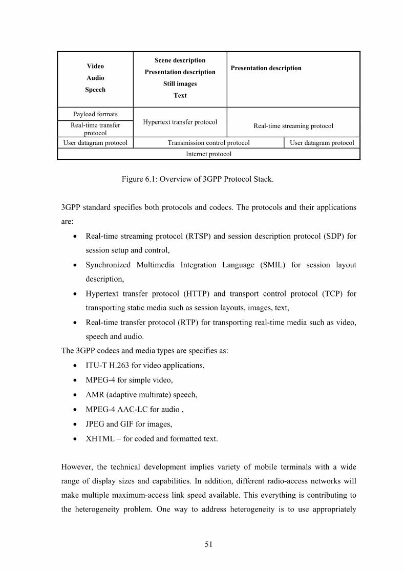
Video
Audio
Speech
Scene description
Presentation description
Still images
Text
Presentation description
Payload formats Real-time transfer
protocol Hypertext transfer protocol
Real-time streaming protocol
User datagram protocol Transmission control protocol User datagram protocol Internet protocol
Figure 6.1: Overview of 3GPP Protocol Stack.
3GPP standard specifies both protocols and codecs. The protocols and their applications
are:
• Real-time streaming protocol (RTSP) and session description protocol (SDP) for
session setup and control,
• Synchronized Multimedia Integration Language (SMIL) for session layout
description,
• Hypertext transfer protocol (HTTP) and transport control protocol (TCP) for
transporting static media such as session layouts, images, text,
• Real-time transfer protocol (RTP) for transporting real-time media such as video,
speech and audio.
The 3GPP codecs and media types are specifies as:
• ITU-T H.263 for video applications,
• MPEG-4 for simple video,
• AMR (adaptive multirate) speech,
• MPEG-4 AAC-LC for audio ,
• JPEG and GIF for images,
• XHTML – for coded and formatted text.
However, the technical development implies variety of mobile terminals with a wide
range of display sizes and capabilities. In addition, different radio-access networks will
make multiple maximum-access link speed available. This everything is contributing to
the heterogeneity problem. One way to address heterogeneity is to use appropriately
51
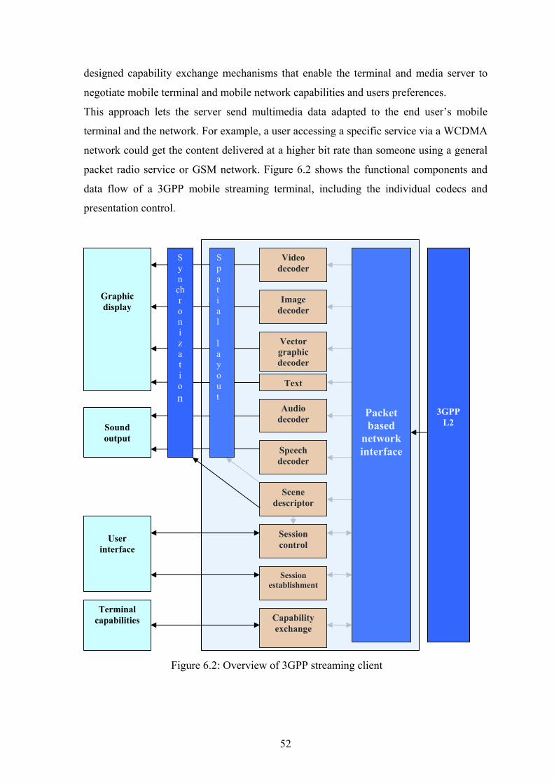
designed capability exchange mechanisms that enable the terminal and media server to
negotiate mobile terminal and mobile network capabilities and users preferences.
This approach lets the server send multimedia data adapted to the end user’s mobile
terminal and the network. For example, a user accessing a specific service via a WCDMA
network could get the content delivered at a higher bit rate than someone using a general
packet radio service or GSM network. Figure 6.2 shows the functional components and
data flow of a 3GPP mobile streaming terminal, including the individual codecs and
presentation control.
Graphic display
Sound output
Video decoder
Image decoder
Text
Vector graphic decoder
Audio decoder
Speech decoder
S p a t i a l l a y o u t
S y n ch r o n i z a t i o n
Packet based
network interface
3GPP
L2
Session control
Session establishment
Scene descriptor
Terminal capabilities
User
interface
Capability exchange
Figure 6.2: Overview of 3GPP streaming client
52
The functional components can be divided into control, scene description, media codecs
and transport of media and control data. The control related elements are session
establishment, capability exchange and session control. The session establishment refers
to methods to invoke a PSS session from a browser or server in the terminal’s user
interface. The capability exchange enables choice or adaptation of media streams
depending on different terminal capabilities. The session control deals with the set-up of
the individual media streams between client and servers. It enables control media streams
by the user. The scene description consists of spatial layout and a description of the
temporal relation between different media that is included in the media presentation.
Transport of media and control data consists of the encapsulation of the coded media and
control data in the transport protocols. Finally, media codecs are specified by 3GPP.
53

6.2 Evolution of Mobile Networks
A technology progress in mobile networks occurred in the late 1970s and early 1980s.
First generation (1G) mobile networks were realized as an analog. They were focused on
voice information, without any data services. The most prominent 1G systems are: NMT
(Nordic Mobile Telephone) was the first commercial analogue mobile system taken into
use in Norway and Sweden in 1979. AMPS (Analog Mobile Phone System) initiated in
USA in 1982 and TACS (Total Access Communication System) exercised in Asia and
Pacific.
Second generation (2G) have been applied in many countries in the half 1990s. The
digital transmission is used mostly for voice calls but also a low data service SMS (Short
Message Service) or fax is feasible. 2G cellular systems include GSM, CDMA (Code
Division Multiple Access) and PDC (Personal Digital Communication) [Puz04].
Towards the third generation (3G), some changes have been realized. Namely, HSCSD
(High Speed Circuit-Switched Data), GPSR (General Packet Radio Service), EDGE
(Enhanced Data for GSM Evolution) and different variants of CDMA; CDMAone and
CDMA2000 [The05]. See Figure 6.3. During the evolution of mobile networks a different
access methods have been used. See Figure 6.4.
Third generation networks have been designed to offer multimedia services and
applications. These packet data networks are adapted for high speed data transmissions.
Figure 6.3: Evolution of Mobile Networks
cdmaOne TIA/IS-95
Circuit-switching (14,4 kbit/s)
cdma2000 1xTreme
DV/3xRTT (<5 Mbit/s)
WCDMA (<2 Mbit/s)
cdma2000 1xEV DO
(<2, 4 Mbit/s)
cdma2000 1xRTT DV
(<144 kbit/s)
GSM Circuit-switching
(<9,6 kbit/s)
GPRS (<171 kbit/s)
EDGE (<384 kbit/s)
2G 2,5 – 2,75G 3G
100+ kbit/s 1+ Mbit/s 10 kbit/s
54
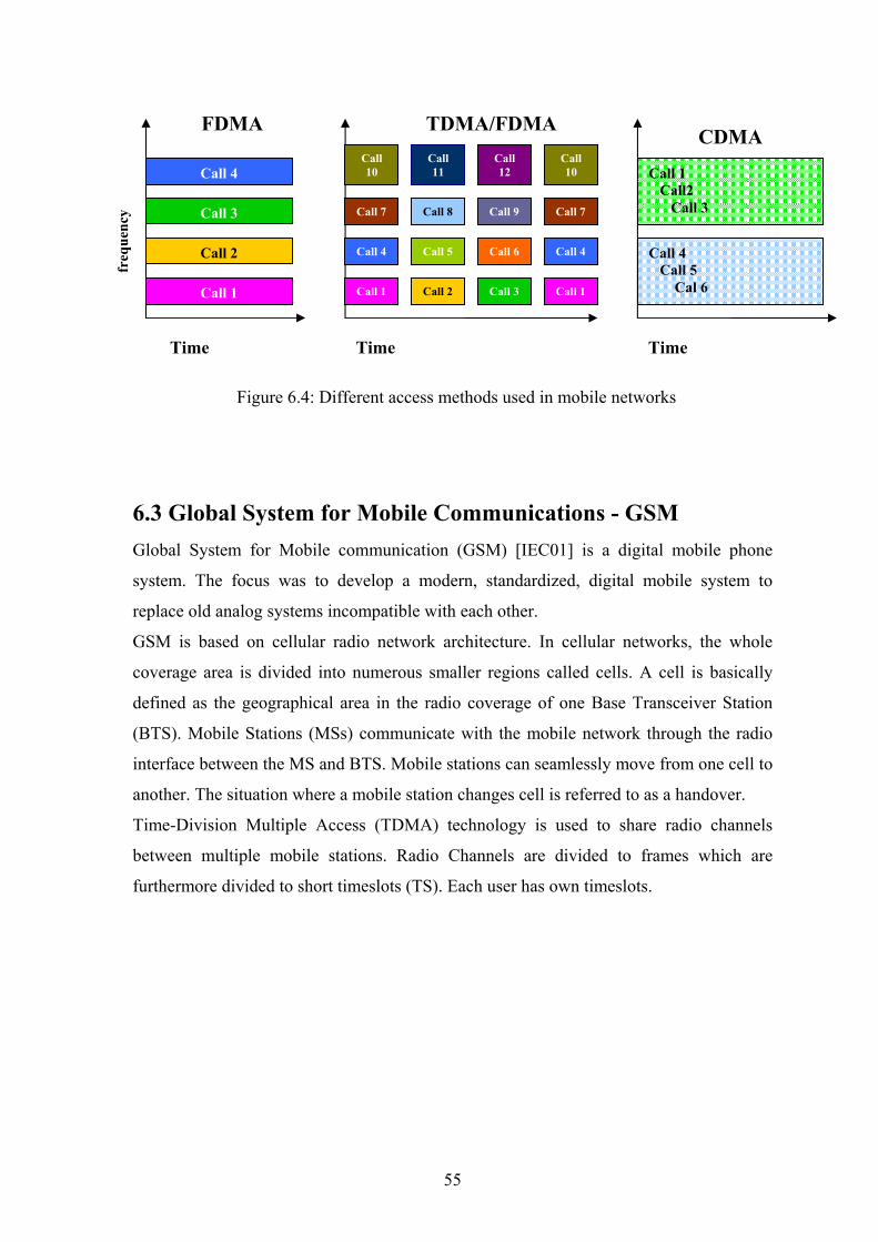
FDMA TDMA/FDMA CDMA
Call 1
Call 2
Call 3
Call 4
Call 1 Call 2 Call 3
Call 6 Call 5 Call 4
Call 9 Call 8 Call 7
Call 12
Call 11
Call 10
Call 1
Call 4
Call 7
Call 10 Call 1
Call2 Call 3
Call 4 Call 5 Cal 6
Time Time Time
freq
uenc
y
Figure 6.4: Different access methods used in mobile networks
6.3 Global System for Mobile Communications - GSM Global System for Mobile communication (GSM) [IEC01] is a digital mobile phone
system. The focus was to develop a modern, standardized, digital mobile system to
replace old analog systems incompatible with each other.
GSM is based on cellular radio network architecture. In cellular networks, the whole
coverage area is divided into numerous smaller regions called cells. A cell is basically
defined as the geographical area in the radio coverage of one Base Transceiver Station
(BTS). Mobile Stations (MSs) communicate with the mobile network through the radio
interface between the MS and BTS. Mobile stations can seamlessly move from one cell to
another. The situation where a mobile station changes cell is referred to as a handover.
Time-Division Multiple Access (TDMA) technology is used to share radio channels
between multiple mobile stations. Radio Channels are divided to frames which are
furthermore divided to short timeslots (TS). Each user has own timeslots.
55
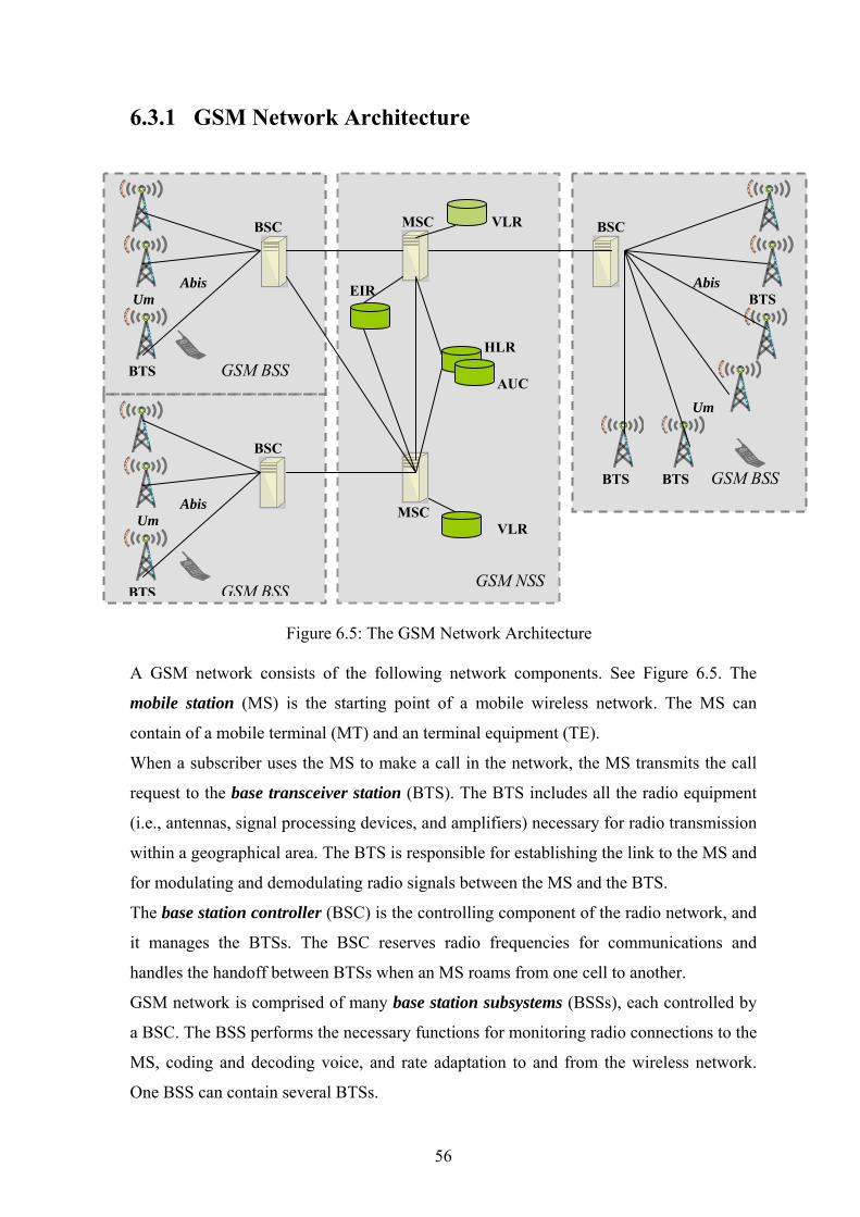
6.3.1 GSM Network Architecture
BSC
Abis Um
BTS GSM BSS
MSC
VLR
EIR HLR AUC
MSC VLR GSM NSS
BSC
Abis Um
BTS GSM BSS
BSC
Abis BTS
Um
BTS BTS GSM BSS
Figure 6.5: The GSM Network Architecture A GSM network consists of the following network components. See Figure 6.5. The
mobile station (MS) is the starting point of a mobile wireless network. The MS can
contain of a mobile terminal (MT) and an terminal equipment (TE).
When a subscriber uses the MS to make a call in the network, the MS transmits the call
request to the base transceiver station (BTS). The BTS includes all the radio equipment
(i.e., antennas, signal processing devices, and amplifiers) necessary for radio transmission
within a geographical area. The BTS is responsible for establishing the link to the MS and
for modulating and demodulating radio signals between the MS and the BTS.
The base station controller (BSC) is the controlling component of the radio network, and
it manages the BTSs. The BSC reserves radio frequencies for communications and
handles the handoff between BTSs when an MS roams from one cell to another.
GSM network is comprised of many base station subsystems (BSSs), each controlled by
a BSC. The BSS performs the necessary functions for monitoring radio connections to the
MS, coding and decoding voice, and rate adaptation to and from the wireless network.
One BSS can contain several BTSs.
56

The mobile switching centre (MSC) is a digital switch that sets up connections to other
MSCs and to the BSCs. The MSCs form the wired backbone of a GSM network and can
switch calls to the public switched telecommunications network (PSTN). The MSC can
connect to a large number of BSCs.
The equipment identity register (EIR) is a database that stores the international mobile
equipment identities (IMEIs) of all the mobile stations in the network. The IMEI is an
equipment identifier assigned by the manufacturer of the mobile station. The EIR
provides security features such as blocking calls from handsets that have been stolen.
The home location register (HLR) is the central database for all users to register to the
GSM network. It stores static information about the subscribers such as the international
mobile subscriber identity (IMSI), subscribed services, and a key for authenticating the
subscriber.
Associated with the HLR is the authentication centre (AuC); this database contains the
algorithms for authenticating subscribers and the necessary keys for encryption to
safeguard the user input for authentication.
The visitor location register (VLR) is a distributed database that temporarily stores
information about the mobile stations that are active in the geographic area for which the
VLR is responsible. A VLR is associated with each MSC in the network. When a new
subscriber roams into a location area, the VLR is responsible for copying subscriber
information from the HLR to its local database. This relationship between the VLR and
HLR avoids frequent HLR database updates and long distance signalling of the user
information, allowing faster access to subscriber information.
The network and switching subsystem (NSS) is the heart of the GSM system. It connects
the wireless network to the standard wired network. It is responsible for the handoff of
calls from one BSS to another and performs services such as charging, accounting, and
roaming.
57
6.3.2 GSM Data Rates The Global System for Mobile Communication was initially developed for voice calls. In
addition to voice calls, GSM technology provides support for data transmission. By using
a Circuit-Switched Data (CSD) service, a GSM phone can be used like a modem to
transfer arbitrary digital data. The bit rate for user data in GSM is 9.6kbps. This data rate
is sufficient mainly for a Short Message Service (SMS), but insufficient for streaming
services. Because the original bit rate of CSD is quite low, some improvements have been
developed to achieve higher bit rates. By using High-Speed Circuit-Switched Data
(HSCSD) [Puz04] technology, a mobile station can use multiple timeslots grouped to one
logical channel. By using 4 timeslots, bit rates as high as 38, 4 kbps can be achieved. In
addition, the bit rate per one timeslot can be raised from 9,6 to 14,4 kbps using enhanced
channel coding technique witch lowers the number of bits used for error correction.
Therefore, the maximum bit rate using 14, 4 kbps channel coding and 4 timeslots is 57, 6
kbps.
6.3.3 Summary Circuit-switched connections are well suited for voice calls, but when they are used for
typical data services, some resources are usually wasted. This happens because in CSD
every data channel is in the exclusive use of only one user, and there are no means to
share it with others.
Second disadvantage is its charging. You should pay for the time and not for the real data
consumed. Since typical data services do not fully utilize the channel most of the time, a
lot of capacity is wasted. However, this could be an advantage with respect to streaming
services. In comparison with typical data services (Web applications), streaming services
utilize the capacity of channel more equally. Effectiveness depends on the network’s
extent of utilization. In the GSM networks the highest priority is assigned to voice calls.
58
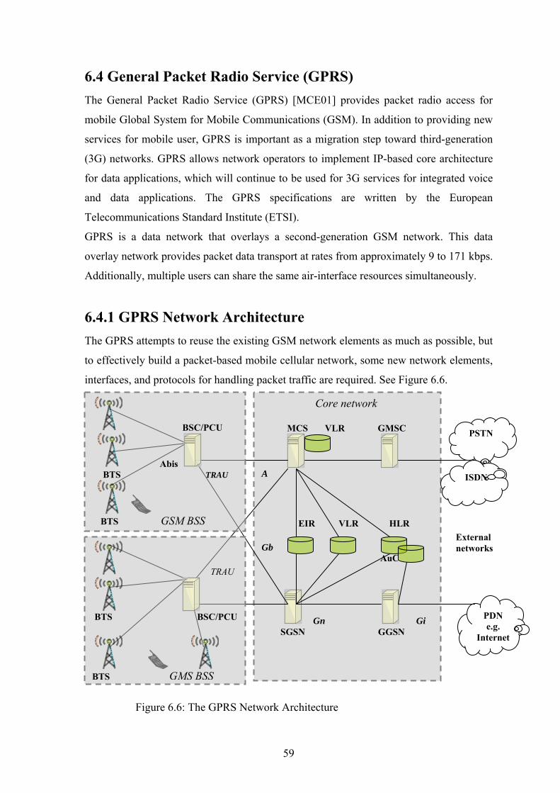
6.4 General Packet Radio Service (GPRS) The General Packet Radio Service (GPRS) [MCE01] provides packet radio access for
mobile Global System for Mobile Communications (GSM). In addition to providing new
services for mobile user, GPRS is important as a migration step toward third-generation
(3G) networks. GPRS allows network operators to implement IP-based core architecture
for data applications, which will continue to be used for 3G services for integrated voice
and data applications. The GPRS specifications are written by the European
Telecommunications Standard Institute (ETSI).
GPRS is a data network that overlays a second-generation GSM network. This data
overlay network provides packet data transport at rates from approximately 9 to 171 kbps.
Additionally, multiple users can share the same air-interface resources simultaneously.
6.4.1 GPRS Network Architecture The GPRS attempts to reuse the existing GSM network elements as much as possible, but
to effectively build a packet-based mobile cellular network, some new network elements,
interfaces, and protocols for handling packet traffic are required. See Figure 6.6.
Core network MCS VLR GMSC
A EIR VLR HLR Gb AuC
Gn Gi SGSN GGSN
PSTN
ISDN
PDN e.g.
Internet
External networks
BSC/PCU
Abis BTS TRAU
BTS GSM BSS
TRAU
BTS BSC/PCU
BTS GMS BSS
Figure 6.6: The GPRS Network Architecture
59
The GPRS terminal equipment is required to access GPRS service. New terminals are
required because existing GSM phones do not handle the enhanced air interface or packet
data. These terminals are backward compatible with GSM for voice calls. The term
terminal equipment is generally used to refer to the variety of mobile phones and mobile
stations that can be used in a GPRS environment. The equipment is defined by terminal
classes and types.
The base station controller (BSC) requires a software upgrade and the installation of new
hardware called the packet control unit (PCU). The PCU provides a physical and logical
data interface to the base station subsystem (BSS) for packet data traffic. When either
voice or data traffic is originated at the subscriber terminal, it is transported over the air
interface to the BTS, and from the BTS to the BSC in the same way as a standard GSM
call. However, at the output of the BSC, the traffic is separated; voice is sent to the
mobile switching centre (MSC) per standard GSM, and data is sent to a new device called
the SGSN via the PCU over a Frame Relay interface.
The Serving GPRS support node (SGSN) delivers packets to mobile stations (MSs)
within its service area. SGSNs send queries to home location registers (HLRs) to obtain
profile data of GPRS subscribers. SGSNs detect new GPRS MSs in a given service area,
process registration of new mobile subscribers, and keep records of their locations inside
a predefined area. The SGSN performs mobility management functions such as handing
off a roaming subscriber from the equipment in one cell to the equipment in another.
The Gateway GPRS support node (GGSN) is used as interface to external IP networks
such as the public Internet. GGSNs maintain routing information that is necessary to
tunnel the protocol data units (PDUs) to the SGSNs that service particular MSs. Other
functions include network and subscriber screening and address mapping. The main
functions of the GGSN involve interaction with the external data network. It routes the
external data network protocol packet encapsulated over the GPRS backbone to the
SGSN currently serving the MS. It also encapsulates and forwards external data network
packets to the appropriate data network and collects charging data that is forwarded to a
charging gateway (CG).
60
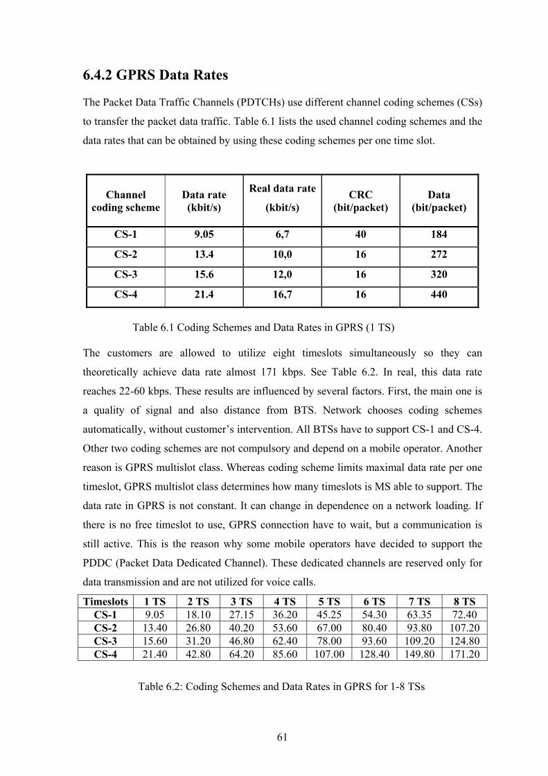
6.4.2 GPRS Data Rates The Packet Data Traffic Channels (PDTCHs) use different channel coding schemes (CSs)
to transfer the packet data traffic. Table 6.1 lists the used channel coding schemes and the
data rates that can be obtained by using these coding schemes per one time slot.
CRC
(bit/packet) Channel
coding scheme Data rate (kbit/s)
Real data rate
(kbit/s)
Data (bit/packet)
CS-1 9.05 6,7 40 184
CS-2 13.4 10,0 16 272
CS-3 15.6 12,0 16 320
CS-4 21.4 16,7 16 440
Table 6.1 Coding Schemes and Data Rates in GPRS (1 TS) The customers are allowed to utilize eight timeslots simultaneously so they can
theoretically achieve data rate almost 171 kbps. See Table 6.2. In real, this data rate
reaches 22-60 kbps. These results are influenced by several factors. First, the main one is
a quality of signal and also distance from BTS. Network chooses coding schemes
automatically, without customer’s intervention. All BTSs have to support CS-1 and CS-4.
Other two coding schemes are not compulsory and depend on a mobile operator. Another
reason is GPRS multislot class. Whereas coding scheme limits maximal data rate per one
timeslot, GPRS multislot class determines how many timeslots is MS able to support. The
data rate in GPRS is not constant. It can change in dependence on a network loading. If
there is no free timeslot to use, GPRS connection have to wait, but a communication is
still active. This is the reason why some mobile operators have decided to support the
PDDC (Packet Data Dedicated Channel). These dedicated channels are reserved only for
data transmission and are not utilized for voice calls.
Timeslots 1 TS 2 TS 3 TS 4 TS 5 TS 6 TS 7 TS 8 TS CS-1 9.05 18.10 27.15 36.20 45.25 54.30 63.35 72.40 CS-2 13.40 26.80 40.20 53.60 67.00 80.40 93.80 107.20 CS-3 15.60 31.20 46.80 62.40 78.00 93.60 109.20 124.80 CS-4 21.40 42.80 64.20 85.60 107.00 128.40 149.80 171.20
Table 6.2: Coding Schemes and Data Rates in GPRS for 1-8 TSs
61
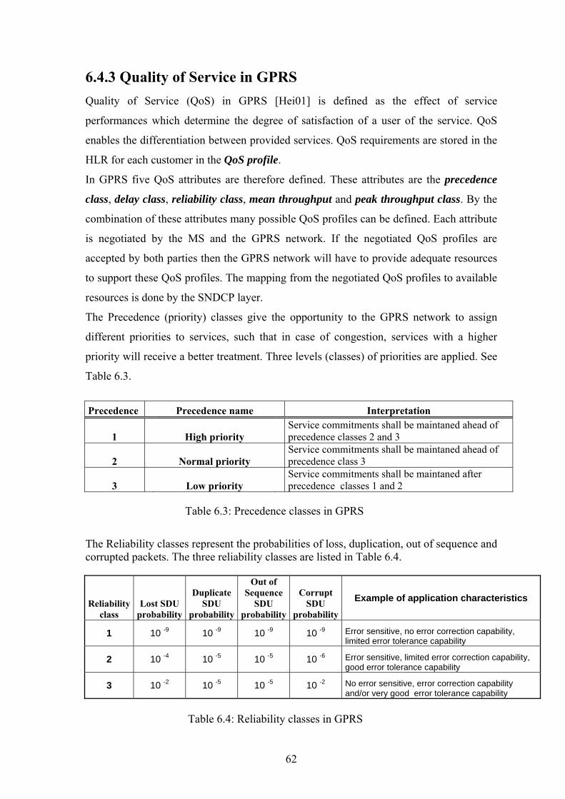
6.4.3 Quality of Service in GPRS
Quality of Service (QoS) in GPRS [Hei01] is defined as the effect of service
performances which determine the degree of satisfaction of a user of the service. QoS
enables the differentiation between provided services. QoS requirements are stored in the
HLR for each customer in the QoS profile.
In GPRS five QoS attributes are therefore defined. These attributes are the precedence
class, delay class, reliability class, mean throughput and peak throughput class. By the
combination of these attributes many possible QoS profiles can be defined. Each attribute
is negotiated by the MS and the GPRS network. If the negotiated QoS profiles are
accepted by both parties then the GPRS network will have to provide adequate resources
to support these QoS profiles. The mapping from the negotiated QoS profiles to available
resources is done by the SNDCP layer.
The Precedence (priority) classes give the opportunity to the GPRS network to assign
different priorities to services, such that in case of congestion, services with a higher
priority will receive a better treatment. Three levels (classes) of priorities are applied. See
Table 6.3.
Precedence Precedence name Interpretation
1 High priority Service commitments shall be maintaned ahead of precedence classes 2 and 3
2 Normal priority Service commitments shall be maintaned ahead of precedence class 3
3 Low priority Service commitments shall be maintaned after precedence classes 1 and 2
Table 6.3: Precedence classes in GPRS
The Reliability classes represent the probabilities of loss, duplication, out of sequence and corrupted packets. The three reliability classes are listed in Table 6.4.
Reliability class
Lost SDU probability
Duplicate SDU
probability
Out of Sequence
SDU probability
Corrupt SDU
probability
Example of application characteristics
1 10 -9 10 -9 10 -9 10 -9 Error sensitive, no error correction capability, limited error tolerance capability
2 10 -4 10 -5 10 -5 10 -6 Error sensitive, limited error correction capability, good error tolerance capability
3 10 -2 10 -5 10 -5 10 -2 No error sensitive, error correction capability and/or very good error tolerance capability
Table 6.4: Reliability classes in GPRS
62

The delay parameter is defined as the end to end transfer time between two MSs or
between a MS and the Gi interface to an external PDN. Two types of delays are specified
as QoS parameters. One of them is the mean delay and the other one is the maximum
delay in 95% of all transfers. Four delay classes are listed for two types of SDU (Service
Data Unit) sizes, i.e., 128 and 1024 octets. See table 6.5.
Delay ( maximum values ) SDU size: 128 octets SDU size: 1025 octets
Delay Class Mean Transfer
Delay(sec) 95 percentile delay(sec)
Mean Transfer Delay(sec
95 percentile delay(sec)
1.(Predictive) < 0.5 < 1.5 < 2 < 7 1.(Predictive) < 5 < 25 < 15 < 75 1.(Predictive) < 50 < 250 < 75 < 375 1.(BestEffort) Unspecified Table 6.5: Delay classes in GPRS
The throughput parameter defines the mean octet rate per hour (19 classes from best
effort to 111kbit/s ~ 50 000 000 octets) and the peak octet rate (9 classes from 8 to
2048kbit/s) measured at the Gi interface.
Form Third Generation Partnership Project (3GPP) specifications [TR 26.937] I chose
one profile for voice and video streaming for a demonstration. In this use case it is
supposed a 3+1 time slot configuration using coding schemes CS1 and CS2. The total
video bit rate is 32.5 kbps (including RTP/UDP/IP header). The total voice bit rate is 7.3
kbps (including RTP/UDP/IP header). The total user bit rate is 39.8 kbps. The values of
QoS parameters are in the Table 6.6.
QoS parameter Parameter value comment
Service precedence 1 Delay class 1 Mean throughput class 17 It means 44 kbps Peak throughput class 4 It means 64 kbps Reliability class 3
Table 6.6: QoS profile for voice and video streaming at an aggregate bit rate of 39.8 kbps
63
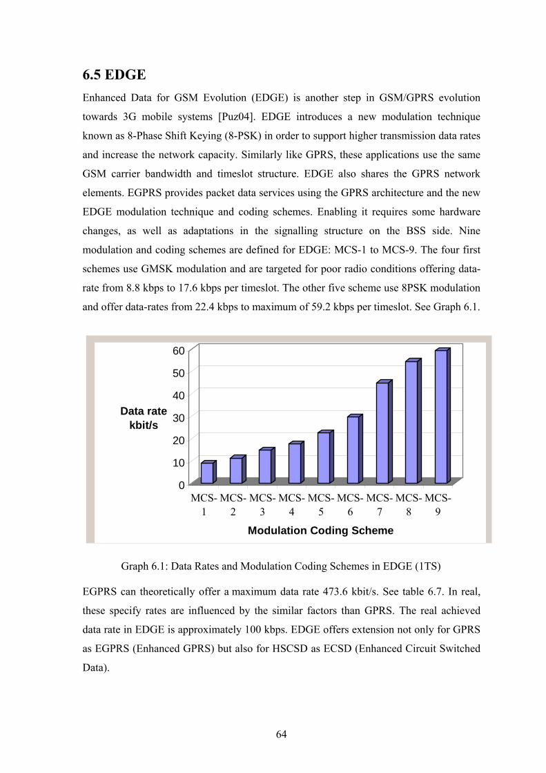
6.5 EDGE Enhanced Data for GSM Evolution (EDGE) is another step in GSM/GPRS evolution
towards 3G mobile systems [Puz04]. EDGE introduces a new modulation technique
known as 8-Phase Shift Keying (8-PSK) in order to support higher transmission data rates
and increase the network capacity. Similarly like GPRS, these applications use the same
GSM carrier bandwidth and timeslot structure. EDGE also shares the GPRS network
elements. EGPRS provides packet data services using the GPRS architecture and the new
EDGE modulation technique and coding schemes. Enabling it requires some hardware
changes, as well as adaptations in the signalling structure on the BSS side. Nine
modulation and coding schemes are defined for EDGE: MCS-1 to MCS-9. The four first
schemes use GMSK modulation and are targeted for poor radio conditions offering data-
rate from 8.8 kbps to 17.6 kbps per timeslot. The other five scheme use 8PSK modulation
and offer data-rates from 22.4 kbps to maximum of 59.2 kbps per timeslot. See Graph 6.1.
0
10
20
30
40
50
60
Data rate kbit/s
MCS-1
MCS-2
MCS-3
MCS-4
MCS-5
MCS-6
MCS-7
MCS-8
MCS-9
Modulation Coding Scheme
Graph 6.1: Data Rates and Modulation Coding Schemes in EDGE (1TS) EGPRS can theoretically offer a maximum data rate 473.6 kbit/s. See table 6.7. In real,
these specify rates are influenced by the similar factors than GPRS. The real achieved
data rate in EDGE is approximately 100 kbps. EDGE offers extension not only for GPRS
as EGPRS (Enhanced GPRS) but also for HSCSD as ECSD (Enhanced Circuit Switched
Data).
64

Timeslots 1 2 3 4 5 6 7 8 MCS-1 8,8 17,6 26,4 35,2 44 52,8 61,6 70,4 MCS-2 11,2 22,4 33,6 44,8 56 67,2 78,4 89,6 MCS-3 14,8 29,6 44,4 59,2 74 88,8 103,6 118,4 MCS-4 17,6 35,2 52,8 70,4 88 105,6 123,2 140,8 MCS-5 22,4 44,8 67,2 89,6 112 134,4 156,8 179,2 MCS-6 29,6 59,2 88,8 118,4 148 177,6 207,2 236,8 MCS-7 44,8 89,6 134,4 179,2 224 268,8 313,6 358,4 MCS-8 54,4 108,8 163,2 217,6 272 326,4 380,8 435,2 MCS-9 59,2 118,4 177,6 236,8 296 355,2 414,4 473,6
Table 6.7: Modulation Coding Schemes and Data Rates in EDGE 6.5.1 Summary General Packet Radio Service (GPRS) and Enhanced Data Rate (EDGE) are services that
provide packet radio access for users of Global System for Mobile Communications
(GSM) technology. It is truly a monumental step in the evolution of mobile
communications towards data centric paradigm.
GPRS and EDGE have been designed as an extension to the existing GSM network
infrastructure to provide a packet data services. They introduce numbers of new
functional elements that support the end-to-end transport of IP based package data. The
main different among these two technologies is in coding schemes. EDGE offers higher
data rate. However, it is influenced by quality of signal. A simple comparison shows
Graph 6.2.
1TS
2TS
3TS
4TS
5TS
6TS
7TS
8TS
0,00
100,00
200,00
300,00
400,00
500,00
Dat
a ra
te k
bit/s
Timeslot
Graph 6.2: Comparison of data rates in EDGE and GPRS
GPRS (CS1) EDGE (MCS1)
GPRS (CS4) EDGE (MCS5)
EDGE (MCS9)
65

Tests in MediaLab in Finland showed that mobile streaming in GPRS or EDGE networks
are rather reliable when the streaming client is not moving. Stream bit rate was set to
22kbps [TS04]. When the client position remains the same, cell changes are not common
and radio link quality is usually very stable. The only major risk is that the used cell
cannot provide enough timeslots for streaming. This is possible especially during peak
hours in urban areas. As the streaming clients move through the city at walking speed,
some cell changes are expected. Handovers do not have much effect on the streaming,
except for a short delay and possibly a few lost packets. The reason is also enough
information in the buffer. The possible lack of network resources is a major problem
especially in dense urban areas.
In the case of higher speeds, streaming is highly affected by mobility. Although the cell
changes do not cause major problems at walking speed, at higher speeds they may be
a problem. This is because the intervals between handovers shorten and the delay for
packet gets longer. This problem usually occurs in dense urban areas where there are a lot
of cells in a small area. Moving fast through terrain may also affect radio channel quality.
However, the worst problem is that it is very likely that some cells along the way cannot
provide the resource required for streaming. When these factors are combined, the result
is that streaming at higher speeds in an urban area is relatively unreliable and highly
affected by many random factors.
It must also be noticed that there are differences between the behaviours of different
network operators. These differenced between networks may be the result of different
hardware and software, different configuration, different network design, or just the result
of random factors. From another point of view, it is necessary to support QoS
provisioning not only over GPRS/EDGE wireless medium but also QoS provisioning
over GPRS core network.
66

6.6 Universal Mobile Telecommunication System
The Universal Mobile Telecommunication System (UMTS) is a third generation (3G)
mobile communications system that provides a range of broadband services to the world
of wireless and mobile communications. It preserves the global roaming capability of
second generation GSM/GPRS networks and provides new enhanced capabilities. The
UMTS is designed to deliver pictures, graphics, video communications, streaming
services, and other multimedia information, as well as voice and data, to mobile wireless
subscribers. The UMTS provides support for both voice and data services [IEC02].
The following data rates are targets for UMTS:
• 144 kbps—Satellite and rural outdoor
• 384 kbps—Urban outdoor
• 2048 kbps—Indoor and low range outdoor
6.6.1 UMTS Network Architecture The major difference between GSM/GPRS networks and UMTS networks is in the air
interface transmission. Time division multiple access (TDMA) and frequency division
multiple access (FDMA) are used in GSM/GPRS networks. The air interface access
method for UMTS networks is wide-band code division multiple access (WCDMA),
which has two basic modes of operation: frequency division duplex (FDD) and time
division duplex (TDD). This new air interface access method requires a new radio access
network (RAN) called the UTMS terrestrial RAN (UTRAN). The UMTS network
architecture is shown in Figure 6.7. The core network requires minor modifications to
accommodate the UTRAN. The UMTS core network is still based on the GSM/GPRS
network topology. It provides the switching, routing, transport, and database functions for
user traffic. The core network contains circuit-switched elements such as the MSC, VLR,
and gateway MSC (GMSC). It also contains the packet-switched elements SGSN and
GGSN. The EIR, HLR, and AuC support both circuit- and packet-switched data. The
Asynchronous Transfer Mode (ATM) is the data transmission method used within the
UMTS core network. ATM Adaptation Layer type 2 (AAL2) handles circuit-switched
connections. Packet connection protocol AAL5 is used for data delivery.
67
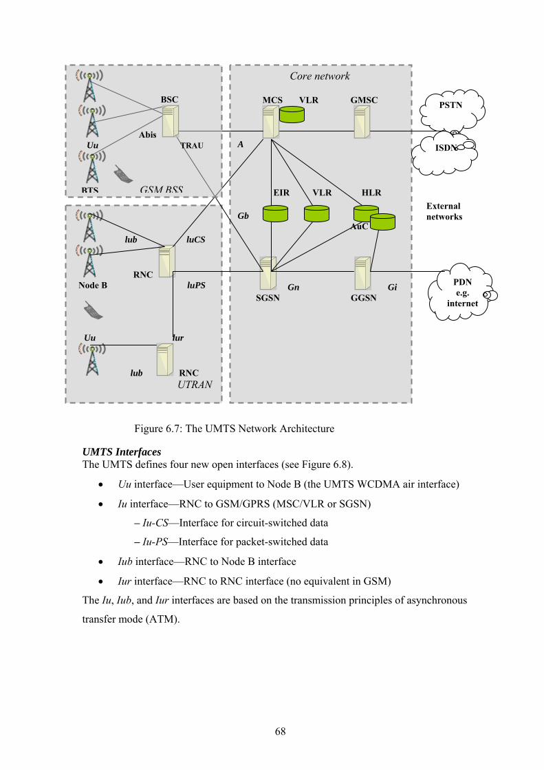
Core network MCS VLR GMSC
A EIR VLR HLR Gb AuC
Gn Gi SGSN GGSN
lub luCS
RNC Node B luPS
Uu lur
lub RNC UTRAN
PSTN
ISDN
PDN e.g.
internet
External networks
BSC
Abis Uu TRAU
BTS GSM BSS
Figure 6.7: The UMTS Network Architecture UMTS Interfaces The UMTS defines four new open interfaces (see Figure 6.8).
• Uu interface—User equipment to Node B (the UMTS WCDMA air interface)
• Iu interface—RNC to GSM/GPRS (MSC/VLR or SGSN)
– Iu-CS—Interface for circuit-switched data
– Iu-PS—Interface for packet-switched data
• Iub interface—RNC to Node B interface
• Iur interface—RNC to RNC interface (no equivalent in GSM)
The Iu, Iub, and Iur interfaces are based on the transmission principles of asynchronous
transfer mode (ATM).
68

UMTS Terrestrial Radio Access Network
Two new network elements are introduced in the UTRAN, namely the radio network
controller (RNC) and Node B. See Figure 6.9.The UTRAN contains multiple radio
network systems (RNSs), and each RNS is controlled by a RNC. The RNC connects to
one or more Node B elements. Each Node B can provide service to multiple cells. The
RNC in UMTS networks provides functions equivalent to the base station controller
(BSC) functions in GSM/GPRS networks. Node B in UMTS networks is equivalent to the
base transceiver station (BTS) in GSM/GPRS networks. In this way, the UMTS extends
existing GSM and GPRS networks.
lub RNC
Node B lu lur Uu RNC lu
lub Node B UTRAN
MSC
SGSN Core network
Figure 6.8: The UMTS Terrestrial Radio Access Network
The radio network controller provides centralized control of the Node B elements in its
covering area. It handles protocol exchanges between UTRAN interfaces. The RNC uses
the Iur interface. There is no equivalent to manage radio resources in GSM/GPRS
networks. In GSM/GPRS networks, radio resource management is performed in the core
network. In UMTS networks, this function is distributed to the RNC, freeing the core
network for other functions. A single serving RNC manages serving control functions
such as connection to the UE, congestion control and handover procedures.
Node B is the radio transmission and reception unit for communication between radio
cells. Each Node B unit can provide service for one or more cells. Node B connects to the
user equipment (UE) over the Uu radio interface using wide-band code division multiple
access (WCDMA). A single Node B unit can support both frequency division duplex
(FDD) and time division duplex (TDD) modes. The main function of Node B is
conversion of data on the Uu radio interface.
69

This function includes error correction and rate adaptation on the air interface. Node B
monitors the quality and strength of the connection and calculates the frame error rate,
transmitting this information to the RNC for processing.
UMTS User Equipment
The UMTS user equipment (UE) is the combination of the subscriber’s mobile equipment
and the UMTS subscriber identity module (USIM). Similar to the SIM in GSM/GPRS
networks, the USIM is a card that inserts into the mobile equipment and identifies the
subscriber to the core network.
6.6.2 QoS in UMTS In this part I would like to explore the main challenges the end-to-end quality of service
(QoS) poses to the third generation (3G) telecommunication architecture and their
solution.
The traditional telecommunication networks (GSM) guarantee a high and fixed QoS by
using circuit switching for real-time applications, which consumes a lot of system
capacity. This is due to the fact that a link is reserved for the entire lifetime of a
connection and the capacity is provided even for times where no data is transferred. On
the other hand, packet switching allows more efficient use of the system capacity.
End-to-end QoS means that the evaluation of the service is done from the end-user
perspective. The end user could be a terminal or even another 3G network. The end-to-
end QoS UMTS requirement implies that QoS management is needed in all involved
domains: wireless domain, IP core, external IP network (DiffServ and IntServ).
UMTS QoS Parameters
The UMTS QoS profile [TS 23.207] is used as the interface for negotiating the
application and network QoS parameters. In this part the UMTS QoS parameters are
mentioned. See Figure 6.9, Table 6.8. The guaranteed bitrate can be understood as the
throughput that the network tries to guarantee. The maximum bit rate is used for policing
in the core network (at the GGSN). These two parameters are similar to the peak and
mean throughput classes in GPRS. The policing function enforces the traffic to be the
compliant with negotiated resources. The SDU error ratio is the average value of error
ratio that the network attempts to keep all the time. In some instants this error ratio could
be higher than the average target, but an upper bound cannot be defined. This is the
residual bit error rate. These two parameters are similar to the Reliability class in GPRS.
70
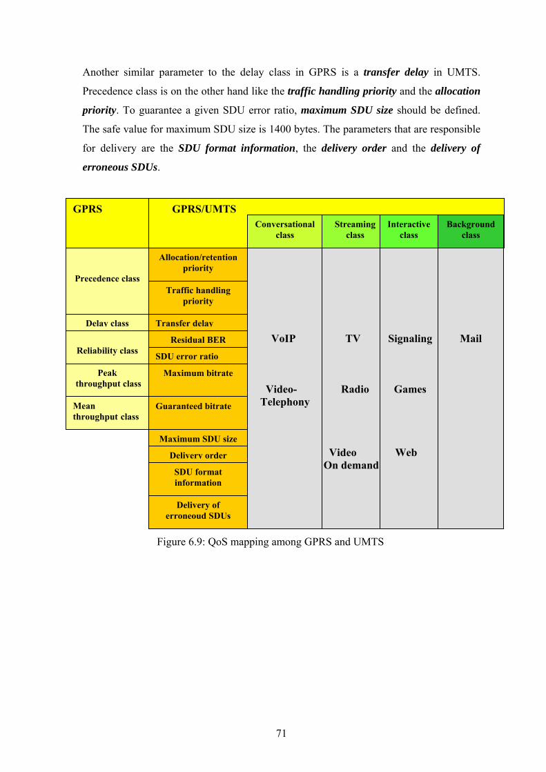
Another similar parameter to the delay class in GPRS is a transfer delay in UMTS.
Precedence class is on the other hand like the traffic handling priority and the allocation
priority. To guarantee a given SDU error ratio, maximum SDU size should be defined.
The safe value for maximum SDU size is 1400 bytes. The parameters that are responsible
for delivery are the SDU format information, the delivery order and the delivery of
erroneous SDUs.
GPRS
Precedence class Traffic handling
priority
Delay class Transfer delay
Allocation/retention priority
Residual BER
SDU error ratio
Maximum bitrate
Mean throughput class
Peak throughput class
Reliability class
SDU format information
Delivery order
Maximum SDU size
Guaranteed bitrate
Delivery of erroneoud SDUs
GPRS/UMTS Conversational
class Streaming
class Interactive
class Background
class
VoIP TV Signaling Mail Video- Radio Games Telephony Video Web On demand
Figure 6.9: QoS mapping among GPRS and UMTS
71

In order to better control the QoS mechanisms, 3GPP demands application traffic
differentiation into a finite number of profiles, named classes. [Chio04]
UMTS QoS Classes
1. Conversational Class: provides as its name implies conversational services. They
comprise real-time symmetric services as voice over IP or video telephony.
Human perception of the maximum transfer delay defines the characteristics of
this traffic class.
2. Streamig Class: Comprise typically one-way real-time services used by a human
destination. Examples of these services include news stream, web radio. For
these services low delay is not a stringent requirement due to application level
buffering in UE and UTRAN. The buffering offers to the end user the
appearance of a real-time service. Codec usage needs to be negotiated as for the
Conversational class.
3. Interactive Class: Provides an asymmetric non real-time service with more capacity for
the downlink than for the uplink. Interactive Web is example of interactive
service. If packet error happens the retransmission increases the delay thus
diminishing the QoS. Low bit error rate is essential for this class.
4. Background Class: Background class services are characterized by the fact that the
destination is not expecting the data to arrive within a certain time. Examples of
these services include the background delivery of emails, files, SMS. This class
requires that the packets should be transmitted with a low bit error rate.
72

Traffic class Conversational class Streaming class Interactive class Backround class
Maximum bit rate
(kbps) < 2048 < 2048 < 2048 < 2048
Delivery order Yes/No Yes/No Yes/No Yes/No
Maximum SDU size < 1500 < 1500 < 1500 < 1500
Delivery of erroneous
SDUs Yes/No/- Yes/No/- Yes/No/- Yes/No/-
Residual BER 5*10-2, 10-2, 5*10-3, 10-3, 10-4,10-6
5*10-2,10-2, 5*10-3,
10-3, 10-4, 10-5, 10-6 4*10-3, 10-5, 6*10-8, 4*10-3, 10-5, 6*10-8
SDU error ratio 10-2, 7*10-3, 10-3,
10-4, 10-5
10-1, 10-2, 7*10-3,
10-3, 10-4, 10-5 10-3, 10-4, 10-6 10-3, 10-4,10-6
Transfer delay (ms) max 100 max 250
Guaranteed bit rate
(kbps) <2048 2048
Table 6.8: QoS Attributes for UMTS classes
From Third Generation Partnership Project (3GPP) [TR 26.937] specifications I chose
one profile for voice and video streaming for a demonstration. The total video bit rate is
47.7 kbps (including RTP/UDP/IP4 headers). The total voice bit rate is 10.1 kbps
(including RTP/UDP/IP header). The total user bit rate is 57.8 kbps. Table 6.9 shows the
QoS parameters for this aggregate bit rate.
QoS parameter Parameter value
Delivery of erroneous SDUs No
Delivery order No Traffic class Streaming Maximum SDU size 1400 bytes Guaranteed bitrate for downlink Ceil (59.3)=60 kbps
Maximum bit rate for downlink Equal or higher than guaranteed bit rate
Guaranteed bitrate for uplink [Ceil(0.12)=1] <= x <= [Ceil(1.5)=2] kbps
Maximum bit rate for uplink Equal or higher than guaranteed bit rate
Residual BER 10-5
SDU error ratio 10-4
Traffic handling priority Subscribed traffic handling priority Transfer delay 250 ms
Table 6.9: QoS profile for voice and video streaming at an aggregate bit rate of 57.8 kbps
73

UMTS QoS architecture From a QoS point of view the UMTS is a network of services. As defined by Third
Generation Partnership Project (3GPP) UMTS relies on a layered Bearer Service (BS)
architecture, where each layer is using the services of the layers below while providing its
services to the layers above, as shown in the bearer architecture diagram of Figure.6.10.
Each bearer service is defined using its QoS parameters, which define such things as
traffic type, bit rates, error ratio [Chio04].
TE MT RAN GSSN GGSN TE
End – to – End Service
TE/MT Local Bearer Service
UMTS Bearer Service External Bearer Service
Radio Access Bearer Service
CN Bearer Service
Radio Bearer Service
RAN Access Bearer Service
Backbone Bearer Service
Physical Radio Bearer Service
Physical Bearer Service
Figure 6.10: The UMTS QoS Architecture
The upper layer end-to-end service is seen as a Bearer Service (BS), with service source
and service destination. In the UMTS model the end-to-end service is built upon three
services: local BS, UMTS BS service and the external BS. Local BS translates between
the end-user service attributes in TE and MT. UMTS BS is the provider of the services
that the UMTS network offers. It covers the RAN and the CN domain. External BS maps
the UMTS bearer service to the QoS attributes of the external network service.
74
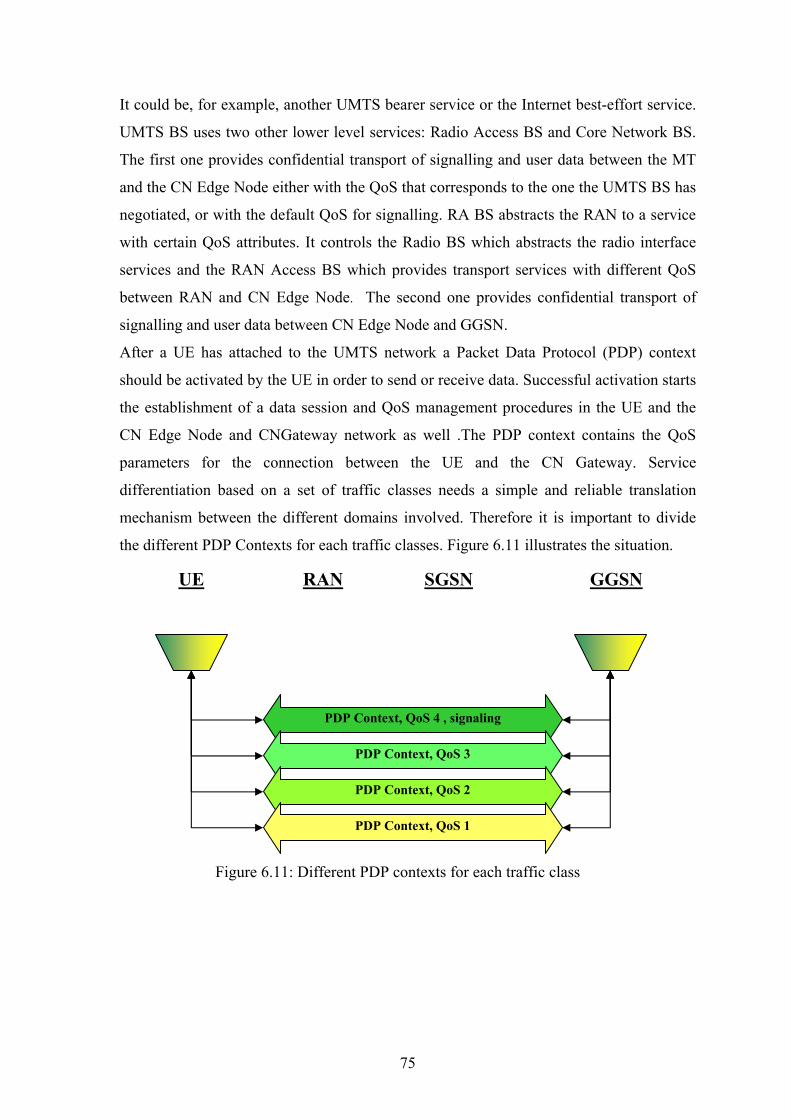
It could be, for example, another UMTS bearer service or the Internet best-effort service.
UMTS BS uses two other lower level services: Radio Access BS and Core Network BS.
The first one provides confidential transport of signalling and user data between the MT
and the CN Edge Node either with the QoS that corresponds to the one the UMTS BS has
negotiated, or with the default QoS for signalling. RA BS abstracts the RAN to a service
with certain QoS attributes. It controls the Radio BS which abstracts the radio interface
services and the RAN Access BS which provides transport services with different QoS
between RAN and CN Edge Node. The second one provides confidential transport of
signalling and user data between CN Edge Node and GGSN.
After a UE has attached to the UMTS network a Packet Data Protocol (PDP) context
should be activated by the UE in order to send or receive data. Successful activation starts
the establishment of a data session and QoS management procedures in the UE and the
CN Edge Node and CNGateway network as well .The PDP context contains the QoS
parameters for the connection between the UE and the CN Gateway. Service
differentiation based on a set of traffic classes needs a simple and reliable translation
mechanism between the different domains involved. Therefore it is important to divide
the different PDP Contexts for each traffic classes. Figure 6.11 illustrates the situation.
UE RAN SGSN GGSN
PDP Context, QoS 4 , signaling
PDP Context, QoS 3
PDP Context, QoS 2
PDP Context, QoS 1
Figure 6.11: Different PDP contexts for each traffic class
75
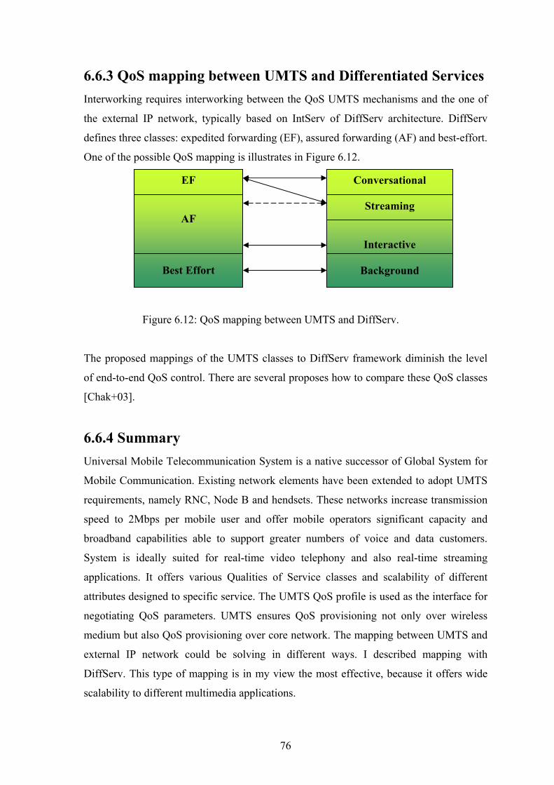
6.6.3 QoS mapping between UMTS and Differentiated Services Interworking requires interworking between the QoS UMTS mechanisms and the one of
the external IP network, typically based on IntServ of DiffServ architecture. DiffServ
defines three classes: expedited forwarding (EF), assured forwarding (AF) and best-effort.
One of the possible QoS mapping is illustrates in Figure 6.12.
EF
AF
Best Effort
Conversational
Streaming
Interactive
Background
Figure 6.12: QoS mapping between UMTS and DiffServ.
The proposed mappings of the UMTS classes to DiffServ framework diminish the level
of end-to-end QoS control. There are several proposes how to compare these QoS classes
[Chak+03].
6.6.4 Summary
Universal Mobile Telecommunication System is a native successor of Global System for
Mobile Communication. Existing network elements have been extended to adopt UMTS
requirements, namely RNC, Node B and hendsets. These networks increase transmission
speed to 2Mbps per mobile user and offer mobile operators significant capacity and
broadband capabilities able to support greater numbers of voice and data customers.
System is ideally suited for real-time video telephony and also real-time streaming
applications. It offers various Qualities of Service classes and scalability of different
attributes designed to specific service. The UMTS QoS profile is used as the interface for
negotiating QoS parameters. UMTS ensures QoS provisioning not only over wireless
medium but also QoS provisioning over core network. The mapping between UMTS and
external IP network could be solving in different ways. I described mapping with
DiffServ. This type of mapping is in my view the most effective, because it offers wide
scalability to different multimedia applications.
76
Chapter 7
Streaming Services In this chapter I will describe nowadays streaming services and the main problems
impeded to streaming into the mobile terminals. Moreover, I would like to utilize this
chapter to my personal view to make use of streaming as a service.
7.1 Nowadays Streaming Services Main problems with streaming to the mobile terminals have been concentrated to the bit
rate available for customers. The major obstacle for mobile data transmission was due to
the reason that first mobile networks were designed for voice calls. After some time
mobile networks have became a victim of its own success. Mobile markets have started
offering data services. Providers have gradually adapted their architectures to all IP
networks. The packet switching network is the network of choice from a provider’s point
of view. Video-calls together with streaming are the most attractive services.
Nowadays streaming services are very closely associated with third generation mobile
networks. By increasing of network capacity new services with higher quality can be
provided. Streaming services have one great advantage. Their contents are not stored in
the terminal’s memory. This is undoubtedly a benefit from the view of content protection.
Among basic and well-known services also belong live TV broadcasting, live radio
broadcasting and Video on Demand service.
7.1.1 Live TV Broadcasting This service allows TV watching on the terminal’s display online. Customers are able to
choose TV program from the provider’s playlist. They can tune in to the action that is
happening at any given time. In my view the highest efficiency in this service is its
mobility. Customers may spend the time travelling by bus, train, coach, tube or
underground more effectively. Another use of this service I can see in the areas where
there is no TV signal broadcasting. In these areas or temporary places customers are thus
able to watch what they want. Note that users can not fast-forward or rewind through the
clip because the event is happening in real time.
77

7.1.2 Live Radio Broadcasting This is a very similar service to TV broadcasting. The main difference is that the
requested content is just a sound. You can listen to the radio wherever the area is covered
by provider’s signal. Accordingly, choice is limited by provider’s playlist.
7.1.3 Video on Demand The service is like a video renting from a 24-hour video store. A database could be full of
films, cartoons, sports matches, education document etc. A clip is available to user
whenever he wants it. These types of clips are pre-recorded and stored on the streaming
servers. There could be thousands of different clips. You can see your favourite clip
anytime.
7.2 Future Streaming Services In this part some of the future streaming services primarily for the streaming class defined
by UMTS will be suggested. With the increasing progress of mobile networks and mobile
terminals, new services are expected. I would like to propose some new streaming
services and also possibility to extend existing ones. Live TV broadcasting is undoubtedly
one of the most attractive services offered by 3G network. You can tune your favourite
TV program anywhere. In my opinion the main drawback of this service is its limited
playlist. In comparison to Internet possibilities it still runs behind. Very similar case is
video on demand service. However, it is matter of time. New possibilities in streaming
services from my point of view are in an advertisement, news, education, security and
free time activities.
78
7.2.1 Mobile Advertisement The area of advertisement is widely applied. The producers are designed to advertise their
proven and perfect products so why don’t utilize it. Mobile video advertisements could be
very interesting solution for them. Mobile advertisements also offer new opportunities for
film producers and film companies. The small trailers of a new film, theatrical
performance or music concert could be streaming as an invitation.
For a foreign customers or customers from other roaming operators, sending invitations
about places of interests could be good idea. Customer with its geographical position
would determine an acceptable area of his interests and receive streaming video
invitations into his mobile device consequently.
7.2.2 Mobile Hot News Nowadays, new informations are being spread very fast. In this zone I suggest streaming
to the client´s terminal not only the latest events from the world, sport events but also
regional ones. For example the most famous or the most important moments of the match
could be streamed. Many customers would appreciate it.
7.2.3 Mobile Education In my opinion human wisdom and know-how is still growing thanks to the medium called
Internet. I’m sure that it is very comfortable for everyone to find and improve his
knowledge immediately. Along this line a special courses or lectures could be a solution.
In unpredictable situations a proper course would probably be very practical.
79

7.2.4 Mobile Security This service I suggest to customers that are still afraid of something, their property
especially. There will be a special agreement between mobile provider and a customer.
This fearful customer may check his house, garden or whatever is precious to him
anytime. Otherwise, if inadvertent access occurs you will be informed about it and you
can check the situation consequently. Other utilization could by a control of our relative.
If you are afraid of your children, sick wife or indisposed granny just ask for this service.
And the last example of the possibilities of how to use this service reminds spying. Are
you curious what is your nurse or housemaid doing, just request the mobile security
service.
7.2.5 Mobile Holiday & Entertainment This could have a lot of users. We are often experiencing that promised conditions of
some place differ from the real ones a lot. This problem could be solved by web-cam
implementation throughout the whole world. You decided to visit swimming pool during
summer holiday and all you have to do is just choose from your popular ones and see
their conditions yourself. Then you can either decide to visit it or choose another one.
Similar situations may occur in tourism or during winter in winter resorts. Before or
during the skiing you can change your current winter centre for better one. This solution
could also be helpful in traffic.
80
Chapter 8
Final Remarks The final chapter of this thesis concludes the work by summarising the achievements
presented thought the thesis.
8.1 Conclusions The thesis has provided a detailed discussion about streaming services and their support
from QoS point of view. The following sections summarize the results of the different
areas of investigation along with conclusions.
Study of Streaming Technology
Chapter 2 provides a description and analyse of streaming technology, describe a process
of creating streaming file and streaming media delivery methods.
Summarizing this chapter I conclude that streaming as a process of playing audio or video
files while it is still downloading is a very progressive solution. As the file plays, it uses
up information in the buffer, but while it is playing, more data is being downloaded. This
avoid time consuming downloads of large files.
Study of the Quality of Service
Chapter 3 provides an extensive discussion on Quality of Services and their parameters,
namely delay, jitter, throughput and packet loss. This chapter also describes causes of
mentioned parameters and applications QoS requirements.
Summarizing this chapter I conclude that QoS and their parameters are for real-time
applications undoubtedly necessary. Thanks to QoS parameters we are able to control
application’s requests and ensure effectivity of network utilization. Interactive audio
streaming has very strict end-to-end QoS requirements, especially with respect to the end-
to-end delay, jitter and reliability. The throughput requirements are less demanding.
Video streaming require significantly more bandwidth than audio. The end-to-end QoS
requirements with respect to jitter and reliability are less strict than for audio.
81
Study of Internet Protocols
Chapter 4 provides review of important protocols currently used within the Internet. The
network layer protocols IPv4 and IPv6, transport protocols UDP, TCP and RTP-on-UDP,
resource reservation protocol RSVP and application level protocols HTTP and RTSP
were discussed.
The benefits of the new Internet Protocol regarding real-time media streaming can be
summarized as follows: first, IPv6 extends the protocol by native multicast and security
facilities and second, simplification of the IPv6 protocol header enable faster processing
within intermediate network nodes.
Whereas TCP is not suitable for interactive real-time streaming applications because of
the interference of its congestion control and reliability mechanisms with the
requirements of time-critical applications, UDP provides a simple but sufficient service.
Control mechanisms such as packet ordering need to be implemented on higher levels. As
a result, RTP-on-UDP is recommended for real-time streaming, since it adds valuable
stream information to the packets and provides a feedback mechanism by means of its
control protocol RTCP.
RSVP is currently the resource reservation protocol of choice within the IETF. It is
recommended to be used with real-time streaming applications to negotiate guaranteed or
controlled load end-to-end.
HTTP as a standard protocol can only provide simple stream control; the lack of session
or stream semantics limits its usability. RTSP, in contrast, is a sophisticated stream
control protocol with similar functionality to a “VCR remote control”.
Study of QoS Mechanisms within the Internet
Chapter 5 presented an analysis of application level techniques and network level QoS
mechanisms that have an impact on the QoS of interactive real-time media streaming
applications.
The first group of mechanisms includes various service differentiation mechanisms:
service marking and the mechanisms proposed to support DiffServ. The simple approach
of service marking is not very useful for real-time streaming because it doesn’t provide
suitable differentiation for real-time media streams. Differentiated Services is currently
the preferred dedifferentiation mechanisms within IETF. It outperforms former
differentiation mechanism by supporting flexible service classes witch are not limited to
a pre-defined standards.
82
DiffServ divides the network into several virtual best-effort networks. However, DiffServ
provides forwarding behaviours only on a per-hop basis, it cannot offer end-to-end
service guaranties. Even thought DiffServ has the potential to significantly improve the
network QoS. The IntServ architecture provides network level QoS by controlling the
network delivery service. Real-time streaming applications can request their QoS
demands by means of a resource reservation protocol. IntServ supports guaranteed (hard)
and controlled load (soft) QoS guarantees. The main drawbacks of IntServ are: first,
IntServ relies on support within all networks elements along the transmission path, and
secondly, per-flow state is required in every intermediate network element. This doesn’t
scale successfully in large networks and in particular not within the core of the Internet.
Integration of DiffServ and IntServ suggests the use of DiffServ as a scalable, hop-by-hop
QoS mechanism in the core of the network, and IntServ in the stub networks where
scalability is not a problem.
A different QoS mechanism, IP Label Switching, aims at improving current QoS in the
Internet by means of packet switching techniques. IP label switching is more efficient
than regular IP routing due to the simpler decision making process in the network routers.
This has the potential to reduce the end-to-end delay received by real-time streams by
reducing the processing in every intermediate node.
Adaptation as a general mechanism for adjusting the operation of an application
depending on the QoS provided by the network is very effective for Internet real-time
streaming. If no QoS guarantees are granted, receiver buffering is mandatory in order to
compensate for the jitter. In general, adaptive (dynamic) receiver buffering is preferable
over simple (static) buffering since “optimal” buffering delay estimation depends highly
on the jitter dynamics.
83

Study of Mobile Networks
Chapter 6 describes development of mobile networks, namely GSM, GPRS, EDGE and
UMTS from architecture and QoS points of view. Usability for streaming is also
described.
Summarizing this chapter I conclude that network components addition into the existing
GSM has been absolutely necessary from provider point of view. The main reason I see in
adapting towards 3G mobile networks. These networks are tailored for real-time video-
calls and streaming services by reason of increased transmission speed to 2Mbps. UMTS
networks have also very effective scalable traffic classes and can provide requested
requirements to different services. Even though, GPRS and EDGE as predecessors of
today’s 3G networks are able to provide streaming services the main drawbacks of these
technologies are their lower real transfer bit rates. Customers have to be satisfied with
lower video quality in such cases.
Streaming services Chapter 7 describes nowadays mobile streaming services and proposes areas of interests
from my point of view.
Nowadays mobile streaming services are very closely associated with 3G mobile
networks. In my view the highest efficiency in this service is its mobility. Customers may
spend the time travelling by bus, train, coach, tube or underground more effectively. They
can tune into the action that is happening at any given time. However, increasing progress
of networks and terminals are expected. New possibilities of streaming services from my
point of view are in advertisement, news, education, security, holiday and entertainment.
Final Remarks End-to-end QoS constraints are very strict in the case of real-time audio or video
streaming applications. QoS degradation has a great impact on the usability in terms of
user satisfaction. In order to satisfy the QoS requirements of streaming applications, it is
suggested that these applications are adaptive to the best QoS mechanism available along
the network transmission path. Receiver buffering is mandatory if no hard QoS
guarantees are granted.
84
Bibliography
[Alm92] P. Almquist. Type of Service in the Internet Protocol. In RFC 1349
[B+01] Y. Bernet et al. A Framework for Use of RSVP with DiffServ Network.
In RFC 2998.
[B+97] R. Braden et al. Resource ReSerVation Protocol. In RFC 2205
[BL+96] T. Berners-Lee et al. Hypertext Transfer protocol. In RFC 1945
[CC98] Compaq Computer Corporation, Video Streaming Technology.pdf , 1998.
[DH95] S. Deering and R. Hiden. Internet Protocol, Version 6. In RFC 1883.
[Hei01] G.Heijenk. QoS in GPRS.pdf
[Chak+03] R. Chakravorty et al. QoS Control for UMTS.pdf ,2003
[Chio04] C. Chioraiu, QoS in UMTS.pdf
[IEC01] The International Engineering Consortium, Global System for Mobile
Communication.pdf
[IEC02] The International Engeneering Consorcium, Universal Mobile
Telecommunication System.pdf
[MCE01] Mobile Cisco Exchange, Overview of GSM, GPRS and UMTS.pdf
[Nich98] K. Nichols. Definition of the Differentiated Services Field. In RFC2474
[Pos81] J. Postel. Internet Protocol. In RFC 791.
[Pos80a] J.Postel. User Datagram Protocol. In RFC 768.
[Pos80b] J.Postel. Transmission Control Protocol. In RFC 761.
[Puz04] R.Pužmanová, Computer Press, Širokopásmový Internet, 2004
[S+96] H. Schulzrinne et al. Real-Time Transport Protocol. In RFC 1889
[S+98] H. Schulzrinne et al. Real Time Streaming Protocol. In RFC 2326
[SPG97] S.Schenker, C.Patridge, R.Guerin.Specificaton of Guaranteed Quality of
Service. In RFC 2212
[The05] M.W.Thelander, The 3G Evolution(CDMA2000), 2005
[TR 26.937] 3GPP, Transparent end-to-end packet streaming services (Release 6),
3GPP TR 26.937 v6.0.0 2004-03
[TS 23.207] 3GPP, End-to-End QoS Concept and Architecture (Release 5), 3GPP TS
23.207 v5.5.0, 2202-09
85
[TS 26.234] 3GPP, Transparent end-to-end packet streaming services (Release 6),
3GPP TS 26. 234 v6.3.0, 2005-03
[TS04] TeliaSonera, Testing Streaming in Mobile Networks.pdf ,July2004
[Wro97] J. Wroclawski. The use of RSVP within Integrated Services. In RFC 2210
[Wro97a] J.Wroclawski. Specification of the Controlled-Load Network Element
Service. In RFC 2211
86