broadcast engineer’s handbook -...
TRANSCRIPT
Page 1
BROADCAST ENGINEER’S HANDBOOK
A collection of useful reference datafor TV broadcasting engineers
© ABE Elettronica S.p.A. Oct. 1999
ABE ELETTRONICA S.p.A.
Via Leonardo da Vinci, 92 - 24043 CARAVAGGIO (BG), Italy
Tel. +39-0363-351007, Fax +39-0363-50756
WEB SITE: http://www.abe.it E-mail: [email protected]

Page 2
INDEX
Page
VHF Channel definitions ....................................................................................................................... 3
UHF Channel definitions ..................................................................................................................... 10
Basic standards for TV transmission ............................................................................................ 15
Minimum field strength for which protection may be sought in planning a television service ....................................................................................................... 17
Boundaries of the television service area in rural districts having a low population density .................................................................... 18
CO-Channel interference .................................................................................................................... 19
Frequency offset conditions ............................................................................................................. 21
Directivity of antennas in the reception of television broadcasting ................................. 24
Microwave radiation exposure - principal safety standards ................................................ 25
Coaxial cables ......................................................................................................................................... 27
Wave guides ............................................................................................................................................. 28
TV analogue microwave links ........................................................................................................... 29
VSWR vs. Return loss (dB) ................................................................................................................ 30
Half wave dipole vs. isotropic dipole ............................................................................................. 30
Relationship between dBm, W, dBmV, V ..................................................................................... 31
Cable size vs. maximum current ..................................................................................................... 32
Conversion factors ................................................................................................................................ 33
Useful formulae ...................................................................................................................................... 35
Useful RF calculation ........................................................................................................................... 37
The material contained in this handbook has been collected from a number of sources.ABE Elettronica S.p.A. accepts no responsability for errors or omissions.

Page 3
VHF Channel definitions
BAND CHANNEL CHANNEL LIMITS (MHZ) VISION CARRIER SOUND
CARRIERStandard B (7 Mhz), Australia
IF - 33.15 to 40.15 38.9 33.40 45 to 52 46.25 51.75
I 1 56 to 63 57.25 62.752 63 to 70 64.25 69.753 85 to 92 86.25 91.75
(II) 4 94 to 101 95.25 100.755 101 to 108 102.25 107.75
5A 137 to 144 138.25 143.256 174 to 181 175.25 180.757 181 to 188 182.25 187.75
III 8 188 to 195 189.25 194.759 195 to 202 196.25 201.75
10 208 to 215 209.25 214.7511 215 to 222 216.25 221.75
Standard B (7 Mhz), EuropeIF - 33.15 to 40.15 38.9 33.4
E 2 47 to 54 48.25 53.75I E 3 54 to 61 55.25 60.75
E 4 61 to 68 62.25 67.75E 5 174 to 181 175.25 180.75E 6 181 to 188 182.25 187.75E 7 188 to 195 189.25 194.75
III E 8 195 to 202 196.25 201.75E 9 202 to 209 203.25 208.75
E 10 209 to 216 210.25 215.75E 11 216 to 223 217.25 222.75E 12 223 to 230 224.25 229.75
Page 4
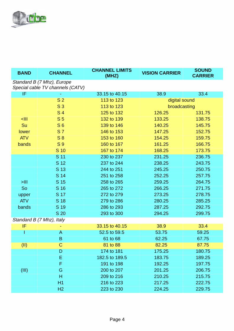
BAND CHANNEL CHANNEL LIMITS (MHZ) VISION CARRIER SOUND
CARRIERStandard B (7 Mhz), EuropeSpecial cable TV channels (CATV)
IF - 33.15 to 40.15 38.9 33.4S 2 113 to 123 digital soundS 3 113 to 123 broadcastingS 4 125 to 132 126.25 131.75
<III S 5 132 to 139 133.25 138.75Su S 6 139 to 146 140.25 145.75
lower S 7 146 to 153 147.25 152.75ATV S 8 153 to 160 154.25 159.75
bands S 9 160 to 167 161.25 166.75S 10 167 to 174 168.25 173.75S 11 230 to 237 231.25 236.75S 12 237 to 244 238.25 243.75S 13 244 to 251 245.25 250.75S 14 251 to 258 252.25 257.75
>III S 15 258 to 265 259.25 264.75So S 16 265 to 272 266.25 271.75
upper S 17 272 to 279 273.25 278.75ATV S 18 279 to 286 280.25 285.25
bands S 19 286 to 293 287.25 292.75S 20 293 to 300 294.25 299.75
Standard B (7 Mhz), ItalyIF - 33.15 to 40.15 38.9 33.4I A 52.5 to 59.5 53.75 59.25
B 61 to 68 62.25 67.75(II) C 81 to 88 82.25 87.75
D 174 to 181 175.25 180.75E 182.5 to 189.5 183.75 189.25F 191 to 198 192.25 197.75
(III) G 200 to 207 201.25 206.75H 209 to 216 210.25 215.75
H1 216 to 223 217.25 222.75H2 223 to 230 224.25 229.75

Page 5
BAND CHANNEL CHANNEL LIMITS (MHZ) VISION CARRIER SOUND
CARRIERStandard B (7 Mhz), Marocco
IF - 33.15 to 40.15 38.9 33.4M 4 162 to 169 163.25 168.75M 5 170 to 177 171.25 176.75M 6 178 to 185 179.25 184.75
III M 7 186 to 193 187.25 192.75M 8 194 to 201 195.25 200.75M 9 202 to 209 203.25 208.75
M 10 210 to 217 211.25 216.75Standard B (7 Mhz), New Zealand
IF - 33.15 to 40.15 38.9 33.41 44 to 51 45.25 50.75
I 2 54 to 61 55.25 60.753 61 to 68 62.25 67.754 174 to 181 175.25 180.755 181 to 188 182.25 187.756 188 to 195 189.25 194.75
III 7 195 to 202 196.25 201.758 202 to 209 203.25 208.759 209 to 216 210.25 215.75
10 216 to 223 217.25 222.75Standard D (8 Mhz), China (Peoples Rep.)
IF - 31.25 to 39.25 38.0 31.51 48.5 to 56.5 49.75 56.252 56.5 to 64.5 57.75 64.25
I 3 64.5 to 72.5 65.75 72.254 76.0 to 84.0 77.25 83.755 84.0 to 92.0 85.25 91.756 167 to 175 168.25 174.757 175 to 183 176.25 182.758 183 to 191 184.25 190.75
III 9 191 to 199 192.25 198.7510 199 to 207 200.25 206.7511 207 to 215 208.25 214.75
Page 6
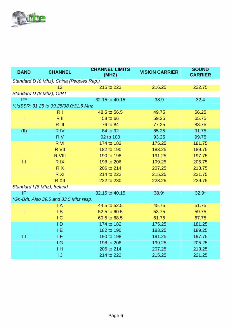
BAND CHANNEL CHANNEL LIMITS (MHZ) VISION CARRIER SOUND
CARRIERStandard D (8 Mhz), China (Peoples Rep.)
12 215 to 223 216.25 222.75Standard D (8 Mhz), OIRT
IF* - 32.15 to 40.15 38.9 32.4*UdSSR: 31.25 to 39.25/38.0/31.5 Mhz
R I 48.5 to 56.5 49.75 56.25I R II 58 to 66 59.25 65.75
R III 76 to 84 77.25 83.75(II) R IV 84 to 92 85.25 91.75
R V 92 to 100 93.25 99.75R VI 174 to 182 175.25 181.75R VII 182 to 190 183.25 189.75R VIII 190 to 198 191.25 197.75
III R IX 198 to 206 199.25 205.75R X 206 to 214 207.25 213.75R XI 214 to 222 215.25 221.75R XII 222 to 230 223.25 229.75
Standard I (8 Mhz), IrelandIF - 32.15 to 40.15 38.9* 32.9*
*Gr.-Brit. Also 39.5 and 33.5 Mhz resp.I A 44.5 to 52.5 45.75 51.75
I I B 52.5 to 60.5 53.75 59.75I C 60.5 to 68.5 61.75 67.75I D 174 to 182 175.25 181.25I E 182 to 190 183.25 189.25
III I F 190 to 198 191.25 197.75I G 198 to 206 199.25 205.25I H 206 to 214 207.25 213.25I J 214 to 222 215.25 221.25
Page 7
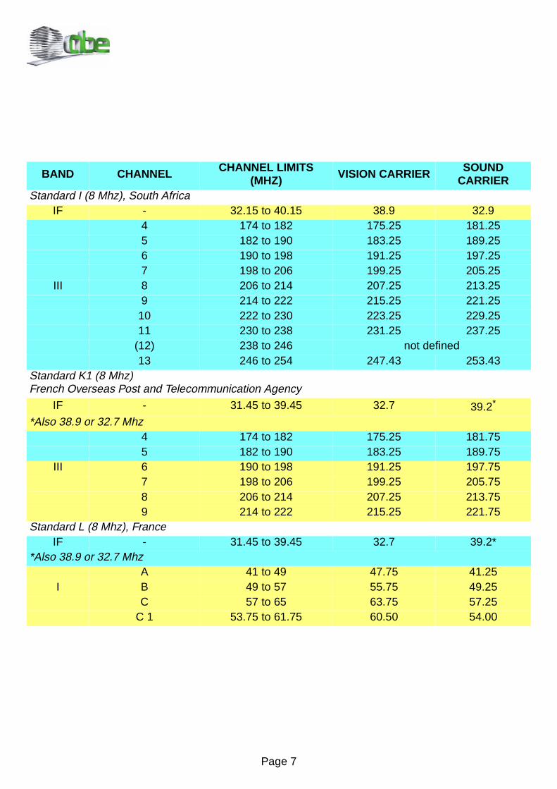
BAND CHANNEL CHANNEL LIMITS (MHZ) VISION CARRIER SOUND
CARRIERStandard I (8 Mhz), South Africa
IF - 32.15 to 40.15 38.9 32.94 174 to 182 175.25 181.255 182 to 190 183.25 189.256 190 to 198 191.25 197.257 198 to 206 199.25 205.25
III 8 206 to 214 207.25 213.259 214 to 222 215.25 221.25
10 222 to 230 223.25 229.2511 230 to 238 231.25 237.25
(12) 238 to 246 not defined13 246 to 254 247.43 253.43
Standard K1 (8 Mhz)French Overseas Post and Telecommunication Agency
IF - 31.45 to 39.45 32.7 39.2*
*Also 38.9 or 32.7 Mhz4 174 to 182 175.25 181.755 182 to 190 183.25 189.75
III 6 190 to 198 191.25 197.757 198 to 206 199.25 205.758 206 to 214 207.25 213.759 214 to 222 215.25 221.75
Standard L (8 Mhz), FranceIF - 31.45 to 39.45 32.7 39.2*
*Also 38.9 or 32.7 MhzA 41 to 49 47.75 41.25
I B 49 to 57 55.75 49.25C 57 to 65 63.75 57.25
C 1 53.75 to 61.75 60.50 54.00
Page 8
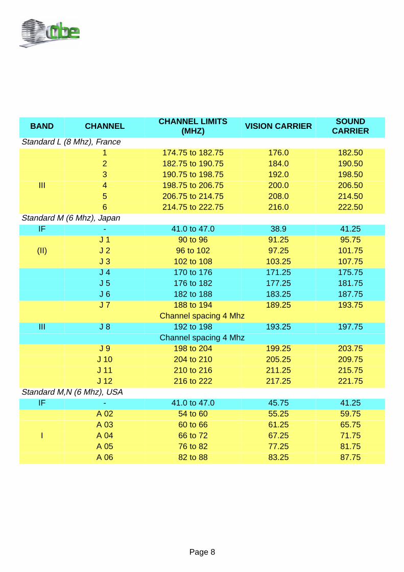
BAND CHANNEL CHANNEL LIMITS (MHZ) VISION CARRIER SOUND
CARRIERStandard L (8 Mhz), France
1 174.75 to 182.75 176.0 182.502 182.75 to 190.75 184.0 190.503 190.75 to 198.75 192.0 198.50
III 4 198.75 to 206.75 200.0 206.505 206.75 to 214.75 208.0 214.506 214.75 to 222.75 216.0 222.50
Standard M (6 Mhz), JapanIF - 41.0 to 47.0 38.9 41.25
J 1 90 to 96 91.25 95.75(II) J 2 96 to 102 97.25 101.75
J 3 102 to 108 103.25 107.75J 4 170 to 176 171.25 175.75J 5 176 to 182 177.25 181.75J 6 182 to 188 183.25 187.75J 7 188 to 194 189.25 193.75
Channel spacing 4 MhzIII J 8 192 to 198 193.25 197.75
Channel spacing 4 MhzJ 9 198 to 204 199.25 203.75
J 10 204 to 210 205.25 209.75J 11 210 to 216 211.25 215.75J 12 216 to 222 217.25 221.75
Standard M,N (6 Mhz), USAIF - 41.0 to 47.0 45.75 41.25
A 02 54 to 60 55.25 59.75A 03 60 to 66 61.25 65.75
I A 04 66 to 72 67.25 71.75A 05 76 to 82 77.25 81.75A 06 82 to 88 83.25 87.75
Page 9
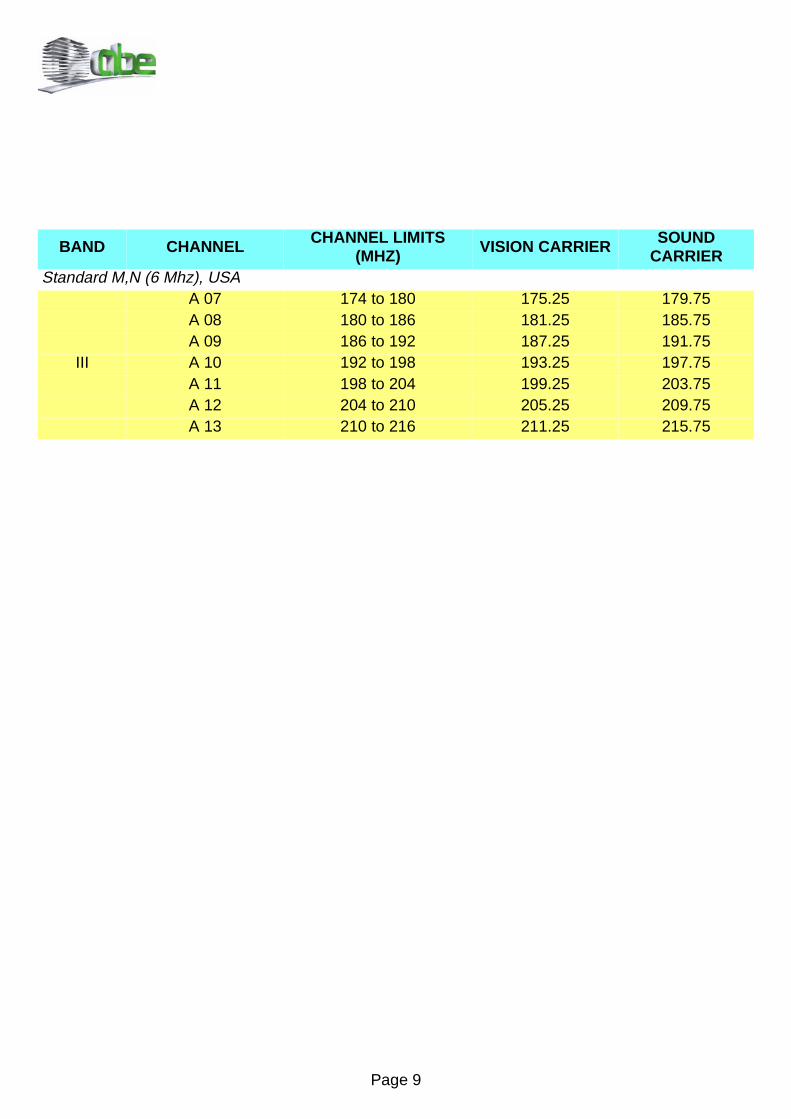
BAND CHANNEL CHANNEL LIMITS (MHZ) VISION CARRIER SOUND
CARRIERStandard M,N (6 Mhz), USA
A 07 174 to 180 175.25 179.75A 08 180 to 186 181.25 185.75A 09 186 to 192 187.25 191.75
III A 10 192 to 198 193.25 197.75A 11 198 to 204 199.25 203.75A 12 204 to 210 205.25 209.75A 13 210 to 216 211.25 215.75
Page 10
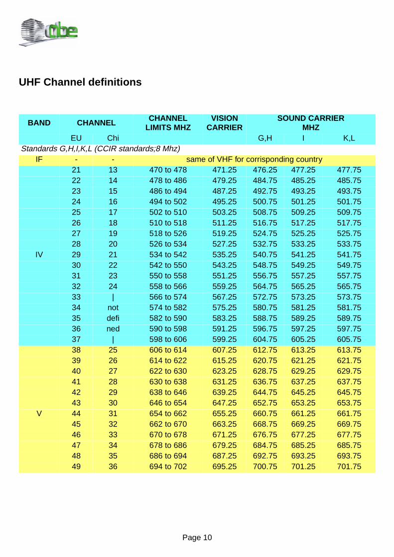
UHF Channel definitions
BAND CHANNEL CHANNEL LIMITS MHZ
VISION CARRIER
SOUND CARRIERMHZ
EU Chi G,H I K,LStandards G,H,I,K,L (CCIR standards;8 Mhz)
IF - - same of VHF for corrisponding country21 13 470 to 478 471.25 476.25 477.25 477.7522 14 478 to 486 479.25 484.75 485.25 485.7523 15 486 to 494 487.25 492.75 493.25 493.7524 16 494 to 502 495.25 500.75 501.25 501.7525 17 502 to 510 503.25 508.75 509.25 509.7526 18 510 to 518 511.25 516.75 517.25 517.7527 19 518 to 526 519.25 524.75 525.25 525.7528 20 526 to 534 527.25 532.75 533.25 533.75
IV 29 21 534 to 542 535.25 540.75 541.25 541.7530 22 542 to 550 543.25 548.75 549.25 549.7531 23 550 to 558 551.25 556.75 557.25 557.7532 24 558 to 566 559.25 564.75 565.25 565.7533 | 566 to 574 567.25 572.75 573.25 573.7534 not 574 to 582 575.25 580.75 581.25 581.7535 defi 582 to 590 583.25 588.75 589.25 589.7536 ned 590 to 598 591.25 596.75 597.25 597.7537 | 598 to 606 599.25 604.75 605.25 605.7538 25 606 to 614 607.25 612.75 613.25 613.7539 26 614 to 622 615.25 620.75 621.25 621.7540 27 622 to 630 623.25 628.75 629.25 629.7541 28 630 to 638 631.25 636.75 637.25 637.7542 29 638 to 646 639.25 644.75 645.25 645.7543 30 646 to 654 647.25 652.75 653.25 653.75
V 44 31 654 to 662 655.25 660.75 661.25 661.7545 32 662 to 670 663.25 668.75 669.25 669.7546 33 670 to 678 671.25 676.75 677.25 677.7547 34 678 to 686 679.25 684.75 685.25 685.7548 35 686 to 694 687.25 692.75 693.25 693.7549 36 694 to 702 695.25 700.75 701.25 701.75
Page 11
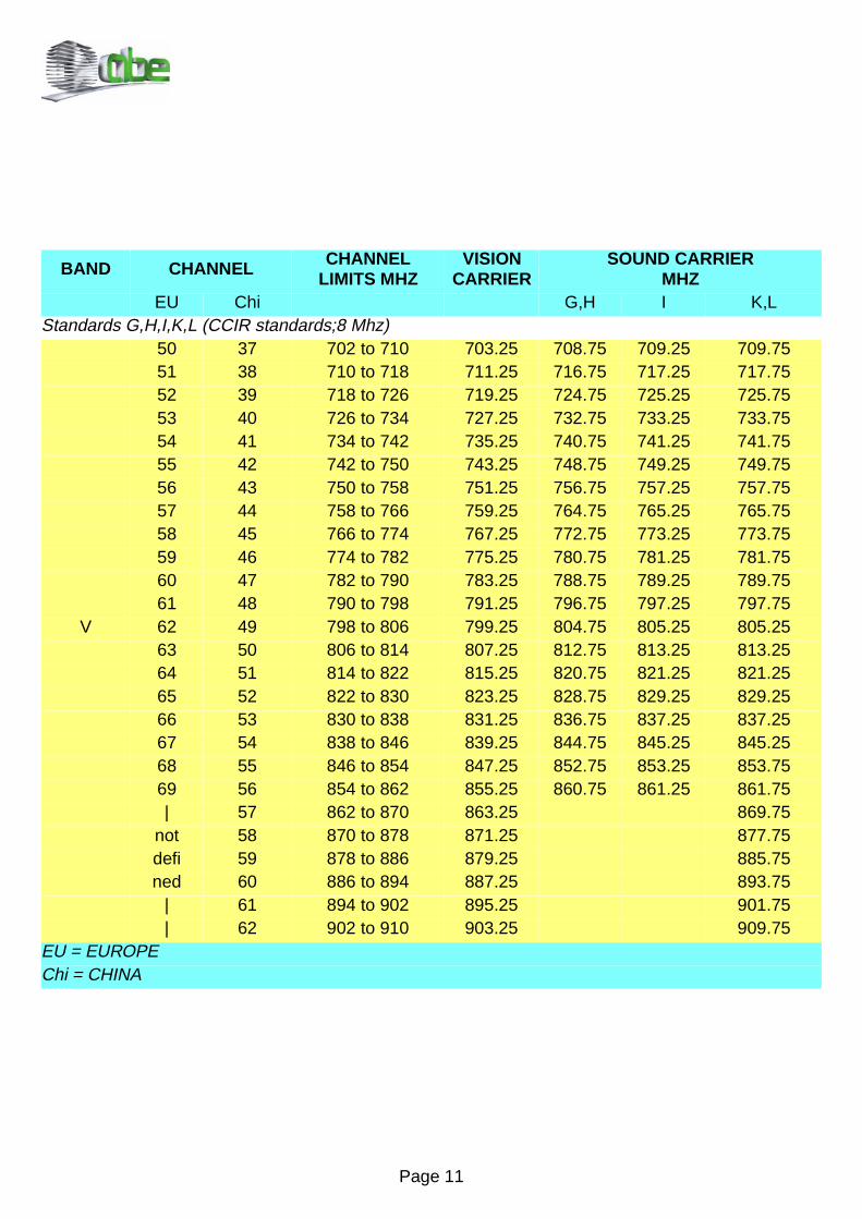
BAND CHANNEL CHANNEL LIMITS MHZ
VISION CARRIER
SOUND CARRIERMHZ
EU Chi G,H I K,LStandards G,H,I,K,L (CCIR standards;8 Mhz)
50 37 702 to 710 703.25 708.75 709.25 709.7551 38 710 to 718 711.25 716.75 717.25 717.7552 39 718 to 726 719.25 724.75 725.25 725.7553 40 726 to 734 727.25 732.75 733.25 733.7554 41 734 to 742 735.25 740.75 741.25 741.7555 42 742 to 750 743.25 748.75 749.25 749.7556 43 750 to 758 751.25 756.75 757.25 757.7557 44 758 to 766 759.25 764.75 765.25 765.7558 45 766 to 774 767.25 772.75 773.25 773.7559 46 774 to 782 775.25 780.75 781.25 781.7560 47 782 to 790 783.25 788.75 789.25 789.7561 48 790 to 798 791.25 796.75 797.25 797.75
V 62 49 798 to 806 799.25 804.75 805.25 805.2563 50 806 to 814 807.25 812.75 813.25 813.2564 51 814 to 822 815.25 820.75 821.25 821.2565 52 822 to 830 823.25 828.75 829.25 829.2566 53 830 to 838 831.25 836.75 837.25 837.2567 54 838 to 846 839.25 844.75 845.25 845.2568 55 846 to 854 847.25 852.75 853.25 853.7569 56 854 to 862 855.25 860.75 861.25 861.75| 57 862 to 870 863.25 869.75
not 58 870 to 878 871.25 877.75defi 59 878 to 886 879.25 885.75ned 60 886 to 894 887.25 893.75
| 61 894 to 902 895.25 901.75| 62 902 to 910 903.25 909.75
EU = EUROPEChi = CHINA
Page 12
BAND CHANNEL CHANNEL LIMITS MHZ
VISION CARRIER SOUND CARRIER
USA JapCan
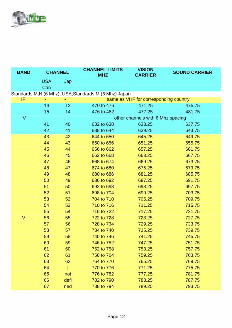
Standards M,N (6 Mhz), USA;Standards M (6 Mhz) JapanIF - - same as VHF for corresponding country
14 13 470 to 476 471.25 475.7515 14 476 to 482 477.25 481.75
IV other channels with 6 Mhz spacing41 40 632 to 638 633.25 637.7542 41 638 to 644 639.25 643.7543 42 644 to 650 645.25 649.7544 43 650 to 656 651.25 655.7545 44 656 to 662 657.25 661.7546 45 662 to 668 663.25 667.7547 46 668 to 674 669.25 673.7548 47 674 to 680 675.25 679.7549 48 680 to 686 681.25 685.7550 49 686 to 692 687.25 691.7551 50 692 to 698 693.25 697.7552 51 698 to 704 699.25 703.7553 52 704 to 710 705.25 709.7554 53 710 to 716 711.25 715.7555 54 716 to 722 717.25 721.75
V 56 55 722 to 728 723.25 727.7557 56 728 to 734 729.25 733.7558 57 734 to 740 735.25 739.7559 58 740 to 746 741.25 745.7560 59 746 to 752 747.25 751.7561 60 752 to 758 753.25 757.7562 61 758 to 764 759.25 763.7563 62 764 to 770 765.25 769.7564 | 770 to 776 771.25 775.7565 not 776 to 782 777.25 781.7566 defi 782 to 790 783.25 787.7567 ned 788 to 794 789.25 793.75
Page 13
BAND CHANNEL CHANNEL LIMITS MHZ
VISION CARRIER SOUND CARRIER
USA JapCan
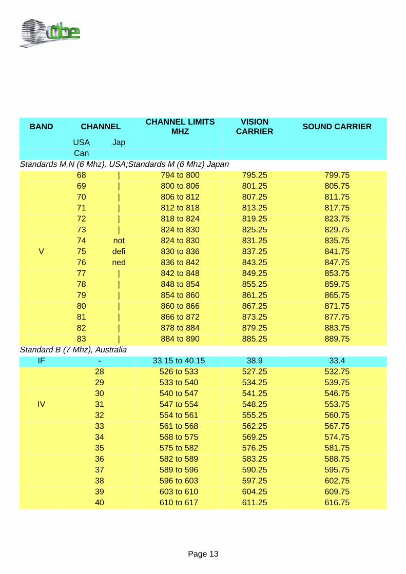
Standards M,N (6 Mhz), USA;Standards M (6 Mhz) Japan68 | 794 to 800 795.25 799.7569 | 800 to 806 801.25 805.7570 | 806 to 812 807.25 811.7571 | 812 to 818 813.25 817.7572 | 818 to 824 819.25 823.7573 | 824 to 830 825.25 829.7574 not 824 to 830 831.25 835.75
V 75 defi 830 to 836 837.25 841.7576 ned 836 to 842 843.25 847.7577 | 842 to 848 849.25 853.7578 | 848 to 854 855.25 859.7579 | 854 to 860 861.25 865.7580 | 860 to 866 867.25 871.7581 | 866 to 872 873.25 877.7582 | 878 to 884 879.25 883.7583 | 884 to 890 885.25 889.75
Standard B (7 Mhz), AustraliaIF - 33.15 to 40.15 38.9 33.4
28 526 to 533 527.25 532.7529 533 to 540 534.25 539.7530 540 to 547 541.25 546.75
IV 31 547 to 554 548.25 553.7532 554 to 561 555.25 560.7533 561 to 568 562.25 567.7534 568 to 575 569.25 574.7535 575 to 582 576.25 581.7536 582 to 589 583.25 588.7537 589 to 596 590.25 595.7538 596 to 603 597.25 602.7539 603 to 610 604.25 609.7540 610 to 617 611.25 616.75

Page 14
BAND CHANNEL CHANNEL LIMITS MHZ
VISIONCARRIER SOUND CARRIER
Standard B (7 Mhz), Australia41 617 to 624 618.25 623.7542 624 to 631 625.25 630.7543 631 to 638 632.25 637.7544 638 to 645 639.25 644.7545 645 to 652 646.25 651.7546 652 to 659 653.25 658.7547 659 to 666 660.25 665.7548 666 to 673 667.25 672.7549 673 to 680 674.25 679.7550 680 to 687 681.25 686.7551 687 to 694 688.25 693.7552 694 to 701 695.25 700.7553 701 to 708 702.25 707.7554 708 to 715 709.25 714.7555 715 to 722 716.25 721.7556 722 to 729 723.25 728.7557 729 to 736 730.25 735.7558 736 to 743 737.25 742.7559 743 to 750 744.25 749.7560 750 to 757 751.25 756.7561 757 to 764 758.25 763.7562 764 to 801 765.25 770.7563 771 to 779 772.25 777.7564 778 to 786 779.25 784.7565 785 to 793 786.25 791.7566 792 to 799 793.25 798.7567 799 to 806 800.25 805.7568 806 to 813 807.25 812.7569 813 to 820 814.25 819.75
USA = United States of AmericaCan = CanadaJap = Japan

Page 15
Basic standards for TV transmission
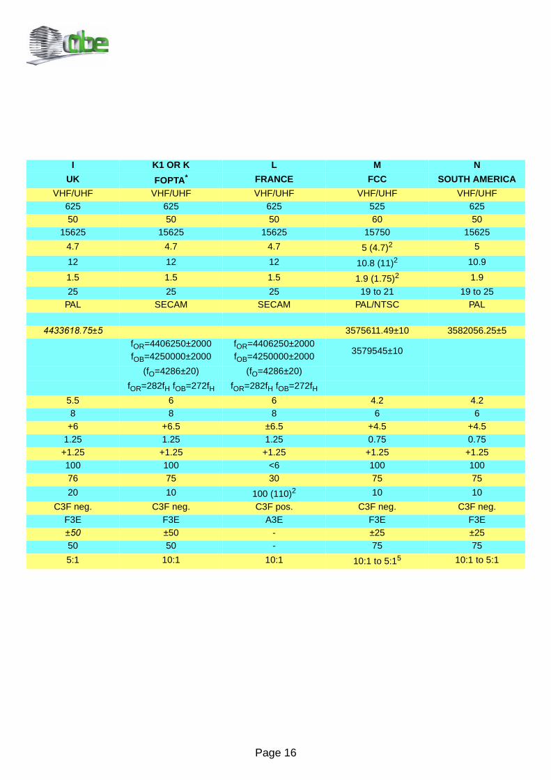
* = group of territories represented by the French Overseas Post and Telecommunication Agency2 = for colour transmission according to NTSC or SECAM3 = 73% instead of nominal 75% applies for TV transmitters of high quality also in the sync range (burst, chrominance signal)4 = 20:1 in the Federal Republic of Germany as of April 1976 for all trasmission of the three programs5 = 6.7:1 and 2.9:1 in Japan6 = for dual-sound or stereo sound in the Federal Republic of Germany
STANDARD B/G D/K HCCIR OIRT BELGIUM
Frequency VHF/UHF VHF/UHF UHFNumber of lines for frame 625 625 625Field frequency Hz 50 50 50Line frequency Hz 15625 15625 15625Duration of line sync pulse µs 4.7 4.7 4.7Duration of line blanking pulse µs 12 12 12Front porch µs 1.5 1.5 1.5Field blanking interval Lines 25 25 25Standard color system PAL/SECAM SECAM PAL/SECAMChrominance subcarrier freq. HzPAL Hz 4433618.75±5 4433618.75±5
SECAM/NTSC HzfOR=4406250±2000fOB=4250000±2000
fOR=4406250±2000fOB=4250000±2000
fOR=4406250±2000fOB=4250000±2000
kHz (fO=4286±20) (fO=4286±20) (fO=4286±20)
fOR=282fH fOB=272fH fOR=282fH fOB=272fH fOR=282fH fOB=272fHVideo bandwidth Mhz 5 6 5RF channel width Mhz 7(B) / 8(G) 8 8
Vision-sound carrier spacing Mhz +5.5 +5.746 +6.5 +5.5
Width of vestigial sideband Mhz 0.75 0.75 1.25Spacing of vision carrier from nearest edge of channel
Mhz +1.25 +1.25 +1.25
RF sync level % 100 100 100RF blanking level % 733 75 75RF white level (residual carrier) % 10 12.5 10Type of vision modulation C3F neg. C3F neg. C3F neg.
Type of sound modulation F3E F3EH6 F3E F3E
Frequency deviation ±50 ±50 ±50Preemphasis µs 50 50 50
Vision/Sound power ratio 10:1 to 20:14 20:1:0.26 10:1 to5:1 5:1 to10:1
Page 16
I K1 OR K L M N
UK FOPTA* FRANCE FCC SOUTH AMERICA
VHF/UHF VHF/UHF VHF/UHF VHF/UHF VHF/UHF625 625 625 525 62550 50 50 60 50
15625 15625 15625 15750 15625
4.7 4.7 4.7 5 (4.7)2 5
12 12 12 10.8 (11)2 10.9
1.5 1.5 1.5 1.9 (1.75)2 1.9
25 25 25 19 to 21 19 to 25PAL SECAM SECAM PAL/NTSC PAL
± 3575611.49±10 3582056.25±5fOR=4406250±2000fOB=4250000±2000
fOR=4406250±2000fOB=4250000±2000
3579545±10
(fO=4286±20) (fO=4286±20)
fOR=282fH fOB=272fH fOR=282fH fOB=272fH5.5 6 6 4.2 4.28 8 8 6 6
+6 +6.5 ±6.5 +4.5 +4.51.25 1.25 1.25 0.75 0.75
+1.25 +1.25 +1.25 +1.25 +1.25100 100 <6 100 10076 75 30 75 75
20 10 100 (110)2 10 10
C3F neg. C3F neg. C3F pos. C3F neg. C3F neg.F3E F3E A3E F3E F3E± ±50 - ±25 ±2550 50 - 75 75
5:1 10:1 10:1 10:1 to 5:15 10:1 to 5:1
Page 17
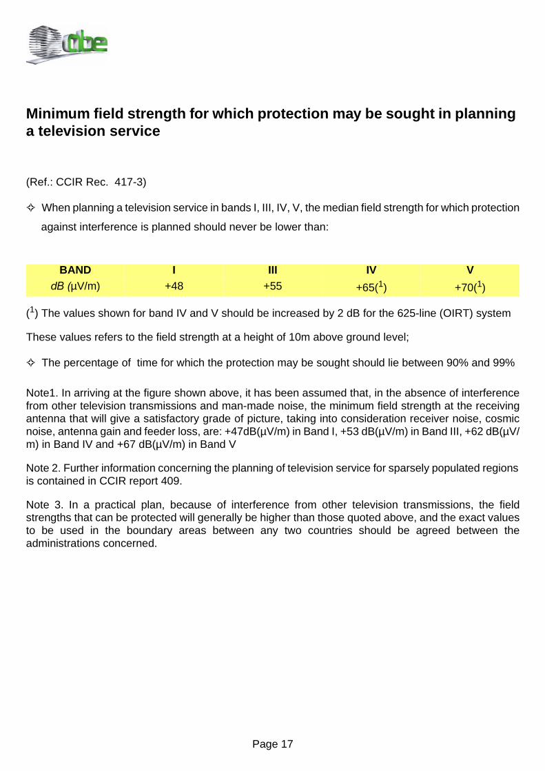
Minimum field strength for which protection may be sought in planning a television service
(Ref.: CCIR Rec. 417-3)
When planning a television service in bands I, III, IV, V, the median field strength for which protection
against interference is planned should never be lower than:
(1) The values shown for band IV and V should be increased by 2 dB for the 625-line (OIRT) system
These values refers to the field strength at a height of 10m above ground level;
The percentage of time for which the protection may be sought should lie between 90% and 99%
Note1. In arriving at the figure shown above, it has been assumed that, in the absence of interferencefrom other television transmissions and man-made noise, the minimum field strength at the receivingantenna that will give a satisfactory grade of picture, taking into consideration receiver noise, cosmicnoise, antenna gain and feeder loss, are: +47dB(µV/m) in Band I, +53 dB(µV/m) in Band III, +62 dB(µV/m) in Band IV and +67 dB(µV/m) in Band V
Note 2. Further information concerning the planning of television service for sparsely populated regionsis contained in CCIR report 409.
Note 3. In a practical plan, because of interference from other television transmissions, the fieldstrengths that can be protected will generally be higher than those quoted above, and the exact valuesto be used in the boundary areas between any two countries should be agreed between theadministrations concerned.
BAND I III IV VG%µV/m) +48 +55 +65(1) +70(1)

Page 18
Boundaries of the television service area in rural districts having a low population density
(Ref.: CCIR Rep. 409 - 4)
Where television services are to be provided for a sparsely populated region, in which better receiversand antenna installation are likely to be employed than those considered in CCIR Rec. 417,administrations may find it desirable to establish the appropriate median field strength for whichprotection against interference is planned as low as shown below.
These values refer to the field strength at a height of 10 m above ground level.
In the absence of interference other than noise, field strength of the order of 40 dB(µV/m) in Band I, 43dB(µV/m) in Band III, 52 dB(µV/m) in Band IV, 58 dB(µV/m) in Band V can give satisfactory pictures;however, it is generally observed that the public begin to lose interest in installing television receptionequipment when the field strength falls much below these levels.
The values given in this Report have been obtained from field-strength investigations at the edge of thecoverage area and picture quality assessments for Bands I and III in rural districts of Australia [CCIR,1963-66], India [CCIR, 1974-78] and Italy, for Bands IV, and V at both rural and urban location in Italyand the United Kingdom [CCIR, 1982-86]. It may be noted that in Bands IV and V where man-madenoise is not generally a problem, the field strength values quoted for rural areas, may also be appliedin urban areas.
BAND I III IV VG%µV/m) +46 +49 +58 +64
Page 19
CO-Channel interference
(Ref.: CCIR Rec. 655)
The protection ratios between two television signals apply only for interference due to the modulatedvision carrier of the unwanted signal. Additional protection may be necessary if the wanted soundcarrier is affected, or if the unwanted sound carrier lies within the wanted vision channel (e.g. theunwanted sound carrier of the system G lies within the vision channel of system K). For all protectionratio figures in this section, the following correction have to be made:
When the wanted signal is modulated negatively and the unwanted signal is modulated positively (L/SECAM), the values should be increased by 2 dB.
When the wanted signal is modulated positively and the unwanted signal is modulated negatively, thevalues shuold be reduced by 2 dB.
Correction is not necessary if the wanted and unwanted signals have the same modulation polarity.
Carriers separated by less then 1000 Hz, non-controlled systems having the same or different line
standard:
Protection ratio: 45 dB, tropospheric interference
Carriers separated by parts of the line frequency, systems having the same line-standard, non-
precision offset:
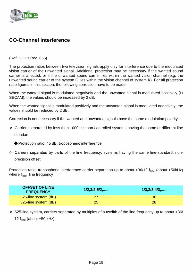
Protection ratio, tropospheric interference carrier separation up to about ±36/12 fline (about ±50kHz)where fline=line frequency
625-line system, carriers separated by multiples of a twelfth of the line frequency up to about ±36/
12 fline (about ±50 kHz):
OFFSET OF LINE FREQUENCY 1/2,3/2,5/2,..... 1/3,2/3,4/3,.....
625-line system (dB) 27 30525-line system (dB) 25 28
Page 20
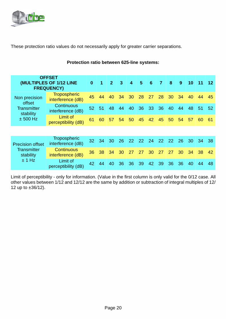
These protection ratio values do not necessarily apply for greater carrier separations.
Protection ratio between 625-line systems:
Limit of perceptibility - only for information. (Value in the first column is only valid for the 0/12 case. Allother values between 1/12 and 12/12 are the same by addition or subtraction of integral multiples of 12/12 up to ±36/12).
OFFSET(MULTIPLES OF 1/12 LINE
FREQUENCY)0 1 2 3 4 5 6 7 8 9 10 11 12
Non precision offset
Transmitter stability
± 500 Hz
Troposphericinterference (dB)
45 44 40 34 30 28 27 28 30 34 40 44 45
Continuousinterference (dB)
52 51 48 44 40 36 33 36 40 44 48 51 52
Limit ofperceptibility (dB)
61 60 57 54 50 45 42 45 50 54 57 60 61
Precision offsetTransmitter
stability ± 1 Hz
Troposphericinterference (dB)
32 34 30 26 22 22 24 22 22 26 30 34 38
Continuousinterference (dB)
36 38 34 30 27 27 30 27 27 30 34 38 42
Limit ofperceptibility (dB)
42 44 40 36 36 39 42 39 36 36 40 44 48

Page 21
Frequency offset conditions
The required protection ratio varies considerably depending on the frequency relationship between thewanted and the unwanted carriers and their frequency tolerance. The greatest protection is requiredwhen the frequency of one or both carriers is non-controlled.
Less interference is possible and therefore lower protection ratios are required for non precision offset(line frequency offset). Non-precision offset takes advantage of the line frequency structure of the videosignal and, in particular, it is advantageous to offset the carriers by multiples of one-half or one-third ofthe line frequency. The long-term stability of these favourable protection ratios can only be guaranteed,however, if the frequencies of the wanted and unwanted signals are kept within ±500Hz.
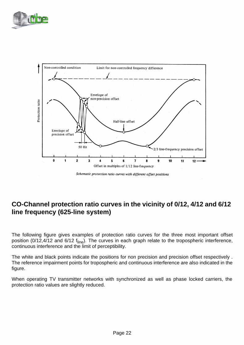
Precision offset takes further advantage of the field frequency structure of the video spectrum. The leastprotection is required when both carriers are precision offset controlled within a tolerance of ±1 Hz forthe wanted and unwanted carriers. In the following figure is shown the main characteristic of offsetoperation which plots in schematic form the protection ratio curves between 0/12 fline and 12/12 fline.These curves are cyclic and their extensions to the left and the right are symbolized by broken lines.These various conditions illustrated are similar within the luminance range up to about ±3 Mhz.
The upper and lower curves indicate, respectively, the protection ratio obtained with non-precision andprecision offset. More precisely, these two curves trace the envelope of a series of fluctuations in theprotection ratio which swings between the two curves at field frequency as represented by the thin line.
Page 22
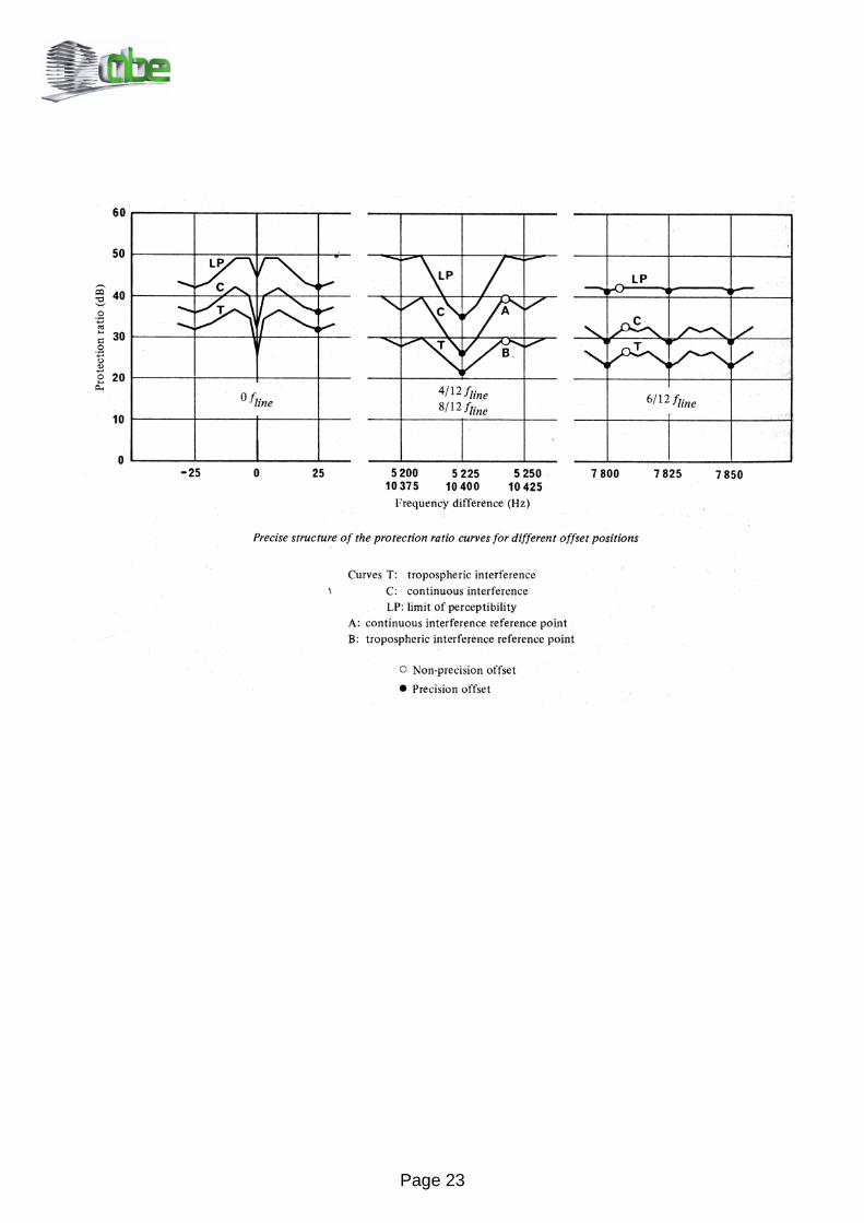
CO-Channel protection ratio curves in the vicinity of 0/12, 4/12 and 6/12 line frequency (625-line system)
The following figure gives examples of protection ratio curves for the three most important offsetposition (0/12,4/12 and 6/12 fline). The curves in each graph relate to the tropospheric interference,continuous interference and the limit of perceptibility.
The white and black points indicate the positions for non precision and precision offset respectively .The reference impairment points for tropospheric and continuous interference are also indicated in thefigure.
When operating TV transmitter networks with synchronized as well as phase locked carriers, theprotection ratio values are slightly reduced.
Page 23
Page 24
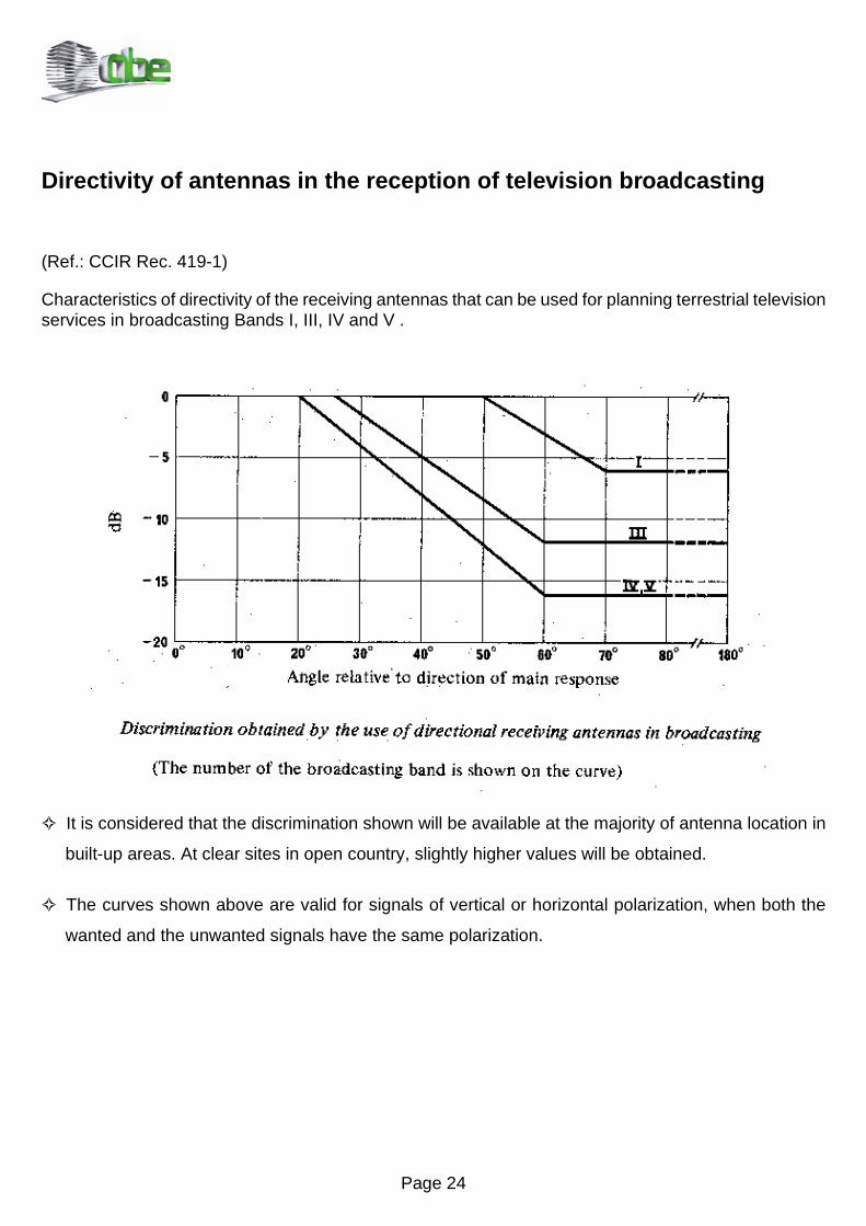
Directivity of antennas in the reception of television broadcasting
(Ref.: CCIR Rec. 419-1)
Characteristics of directivity of the receiving antennas that can be used for planning terrestrial televisionservices in broadcasting Bands I, III, IV and V .
It is considered that the discrimination shown will be available at the majority of antenna location in
built-up areas. At clear sites in open country, slightly higher values will be obtained.
The curves shown above are valid for signals of vertical or horizontal polarization, when both the
wanted and the unwanted signals have the same polarization.

Page 25
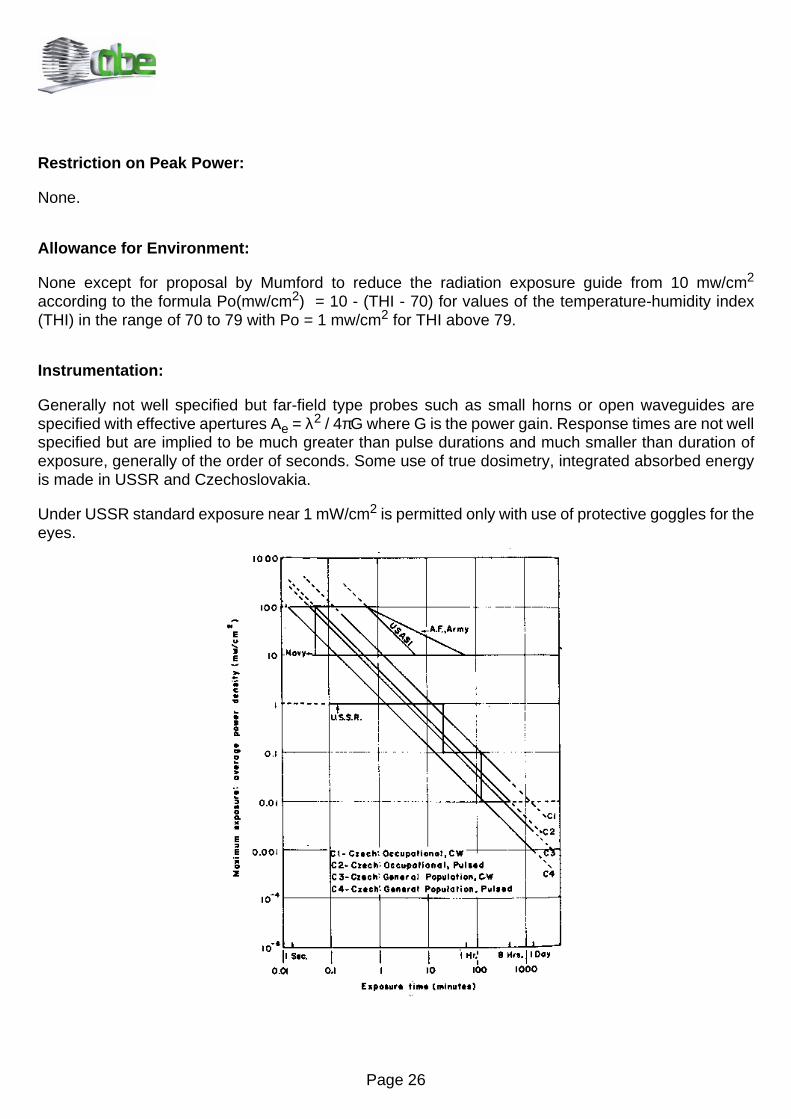
Microwave radiation exposure - principal safety standards
Frequency range:
USAS C95.1 - 10 Mhz - 100 Ghz
Military - all microwave frequencies - range not specified
USSR - 300 Mhz to 30 Ghz
Czech - 300 Mhz to 300 Ghz
Definition of Power Density:
Power Densities referred to in standards is that average density measured in accessible regions(USASI, or military) or at actual exposure sites (USSR and Czech) in the absence of subject.
Averaging time:
USAS C95.1 - 0.1 hour or 6 minutes
AF and ARMY - 0.01 hour or 36 seconds
Navy - 3 seconds
USSR - not specified
Czech - not specified, but the standard implies that an average density is calculated from an integrateddose. For example, for occupational situations the maximum permissible exposure is given by:
averaged over 8 hours where P is power density and T is time in hour. The total exposure dose overfive consecutive working days is summed and divided by 5 to obtain an average exposure dose for 8hours.
Dependence on Area of Exposure:
No distinctions are generally made between partial and whole body exposure.
Modification for Pulse or Other Modulation:
None except for reduction of exposure level by a factor of 2.5 in Czech standards.
3G7 < 200 microwatts / cm - hours2
0
8
∫
Page 26
Restriction on Peak Power:
None.
Allowance for Environment:
None except for proposal by Mumford to reduce the radiation exposure guide from 10 mw/cm2
according to the formula Po(mw/cm2) = 10 - (THI - 70) for values of the temperature-humidity index(THI) in the range of 70 to 79 with Po = 1 mw/cm2 for THI above 79.
Instrumentation:
Generally not well specified but far-field type probes such as small horns or open waveguides arespecified with effective apertures Ae = λ2 / 4πG where G is the power gain. Response times are not wellspecified but are implied to be much greater than pulse durations and much smaller than duration ofexposure, generally of the order of seconds. Some use of true dosimetry, integrated absorbed energyis made in USSR and Czechoslovakia.
Under USSR standard exposure near 1 mW/cm2 is permitted only with use of protective goggles for theeyes.

Page 27
Coaxial cables
CABLETYPE
IMPEDANCEΩ DIELECTRIC VELOCITY
FACTOR
FREQUENCY [MHZ]MAXIMUM POWER [KW] / ATTENUATION [DB/100 M]
50 100Kw dB Kw dB
RG 58 50 Compact Polythene 0.67 0.42 10.8 0.3 16.1RG 59 75 Compact Polythene 0.66 0.75 8.0 0.50 11.2
RG 213 50 Compact Polythene 0.66 2.7 4.27 1.7 6.23RG 8 52 Compact Polythene 0.66 2.7 4.27 1.7 6.23
RG 11 75 Compact Polythene 0.66 1.7 4.80 1.03 7.01/4 Inch 50 Expanded Polythene (FOAM) 0.84 0.985 4.17 0.690 5.941/2 Inch 50 Expanded Polythene (FOAM) 0.81 2.91 2.40 2.03 3.447/8 Inch 50 Expanded Polythene (FOAM) 0.89 7.74 0.843 5.38 1.21
1+5/8 Inch 50 Expanded Polythene (FOAM) 0.88 19.3 0.512 13.4 0.7381/2 Inch 50 Air Dielectric 0.914 2.97 1.90 2.10 2.725/8 Inch 50 Air Dielectric 0.92 6.00 1.12 4.21 1.607/8 Inch 50 Air Dielectric 0.90 9.20 0.853 6.40 1.21
1+5/8 Inch 50 Air Dielectric 0.921 20.7 0.476 14.4 0.6793 Inch 50 Air Dielectric 0.933 54.0 0.322 29.1 0.4484 Inch 50 Air Dielectric 0.92 82.0 0.256 56.0 0.3715 Inch 50 Air Dielectric 0.931 107 0.177 73.0 0.259

Page 28
Wave guides
FREQUENCY [MHZ]Maximum power [Kw] / Attenuation [dB/100 m]
200 500 800 1000 2000 3000 8000Kw dB Kw dB Kw dB Kw dB Kw dB Kw dB Kw dB0.2 24.3 0.18 39.6 0.14 39.8 0.125 55.0 0.08 75.0 0.62 111.5 - -
0.35 16.1 0.23 27.0 0.17 37.0 0.15 43.0 0.09 68.0 0.07 85.0 - -1.1 8.86 0.65 17.0 0.48 23.0 0.40 26.0 0.30 43.0 0.19 57.0 - -1.1 8.86 0.65 17.0 0.48 23.0 0.40 26.0 0.30 43.0 0.19 57.0 - -
0.81 10.03 0.48 17.0 0.36 25.0 0.30 29.0 0.19 46.0 0.15 60.0 - -0.482 8.46 0.298 13.7 0.231 17.5 0.205 19.7 0.14 28.6 0.111 35.8 0.062 62.71.42 4.92 0.867 8.06 0.669 10.4 0.59 11.7 0.4 17.4 0.318 22.1 0.166 42.03.72 1.76 2.25 2.90 1.73 3.78 1.52 4.30 1.01 6.46 0.785 8.31 - -9.22 1.08 5.53 1.79 4.21 2.36 3.69 2.69 2.42 4.10 - - - -1.48 3.90 0.924 6.13 0.720 7.77 0.640 8.69 0.44 12.6 0.338 16.2 0.175 32.22.94 2.29 1.82 3.71 1.41 4.76 1.25 5.37 0.858 7.86 0.682 9.89 - -4.40 1.77 2.69 2.85 2.09 3.68 1.85 4.17 1.30 6.07 1.0 7.90 - -10.0 0.951 6.21 1.57 4.82 2.03 4.30 2.30 2.90 3.44 - - - -25.0 0.682 14.6 1.2 9.24 1.60 9.30 1.84 - - - - - -38.7 0.545 22.6 0.943 17.1 1.24 15.0 1.41 - - - - - -51.0 0.377 30.7 0.626 23.0 0.820 - - - - - - - -
GUIDE TYPETE11MODE CUTOFF
[GHZ]
MAXIMUMFREQ. RANGE
[GHZ]
ATTENUATION[DB/100 M]
MAX POWER[W]
VELOCITYFACTOR
EW 127 A 7.67 10.0 - 13.25 11.83 1.24 0.78EW 132 9.22 11.0 - 15.35 15.84 0.85 0.78
Page 29
TV analogue microwave links
SYSTEM STANDARD
IF FREQUENCY: 70 Mhz
MODULATION TYPE: F.M.
NOMINAL FREQUENCY DEVIATION: 8 Mhz p.p.
(REC. 276-2)
PREEMPHASIS / DEEMPHASIS: 525 Lines Standard or
625 Lines Standard
(REC. 405 - 1)
STANDARD AUDIO CARRIERS
FREQUENCY: 7.500 Mhz (1°)
8.590 Mhz
7.020 Mhz
8.65Mhz
(REP. 289-4)
AUDIO SUBCARRIER MODULATION
TYPE: F.M.
STANDARD NOMINAL MAXIMUM AUDIO
SUBCARRIER DEVIATION
(with audio signal): ±.K]S
STANDARD AUDIO SUBCARRIER
PREEMPHASIS: µ6
Page 30
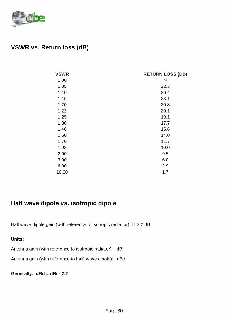
VSWR vs. Return loss (dB)
Half wave dipole vs. isotropic dipole
Half wave dipole gain (with reference to isotropic radiatior) ≅ 2.2 dB
Units:
Antenna gain (with reference to isotropic radiator): dBi
Antenna gain (with reference to half wave dipole): dBd
Generally: dBd = dBi - 2.2
VSWR RETURN LOSS (DB)1.00 ∞1.05 32.31.10 26.41.15 23.11.20 20.81.22 20.11.25 19.11.30 17.71.40 15.61.50 14.01.70 11.71.92 10.02.00 9.53.00 6.06.00 2.910.00 1.7
Page 31
5HODWLRQVKLSEHWZHHQG%P:G%µ99
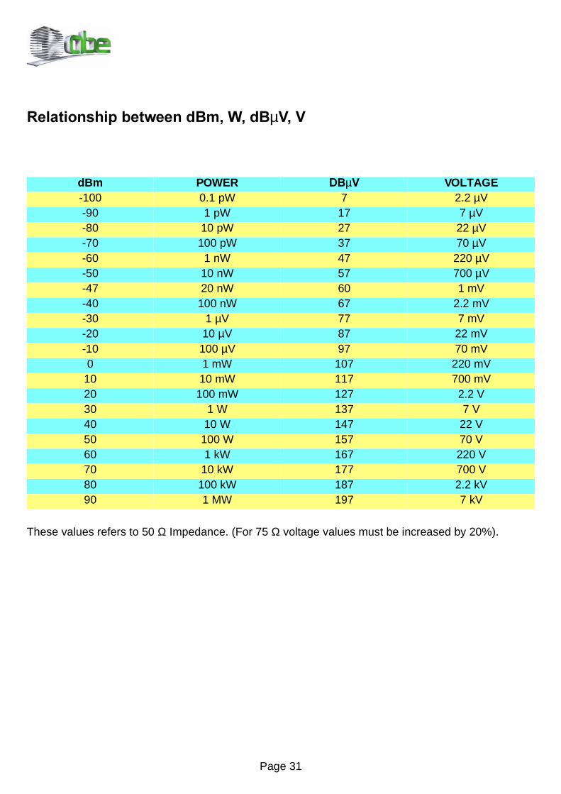
These values refers to 50 Ω Impedance. (For 75 Ω voltage values must be increased by 20%).
dBm POWER '%µ9 VOLTAGE-100 0.1 pW 7 2.2 µV-90 1 pW 17 7 µV-80 10 pW 27 22 µV-70 100 pW 37 70 µV-60 1 nW 47 220 µV-50 10 nW 57 700 µV-47 20 nW 60 1 mV-40 100 nW 67 2.2 mV-30 1 µV 77 7 mV-20 10 µV 87 22 mV-10 100 µV 97 70 mV0 1 mW 107 220 mV
10 10 mW 117 700 mV20 100 mW 127 2.2 V30 1 W 137 7 V40 10 W 147 22 V50 100 W 157 70 V60 1 kW 167 220 V70 10 kW 177 700 V80 100 kW 187 2.2 kV90 1 MW 197 7 kV
Page 32
Cable size vs. maximum current
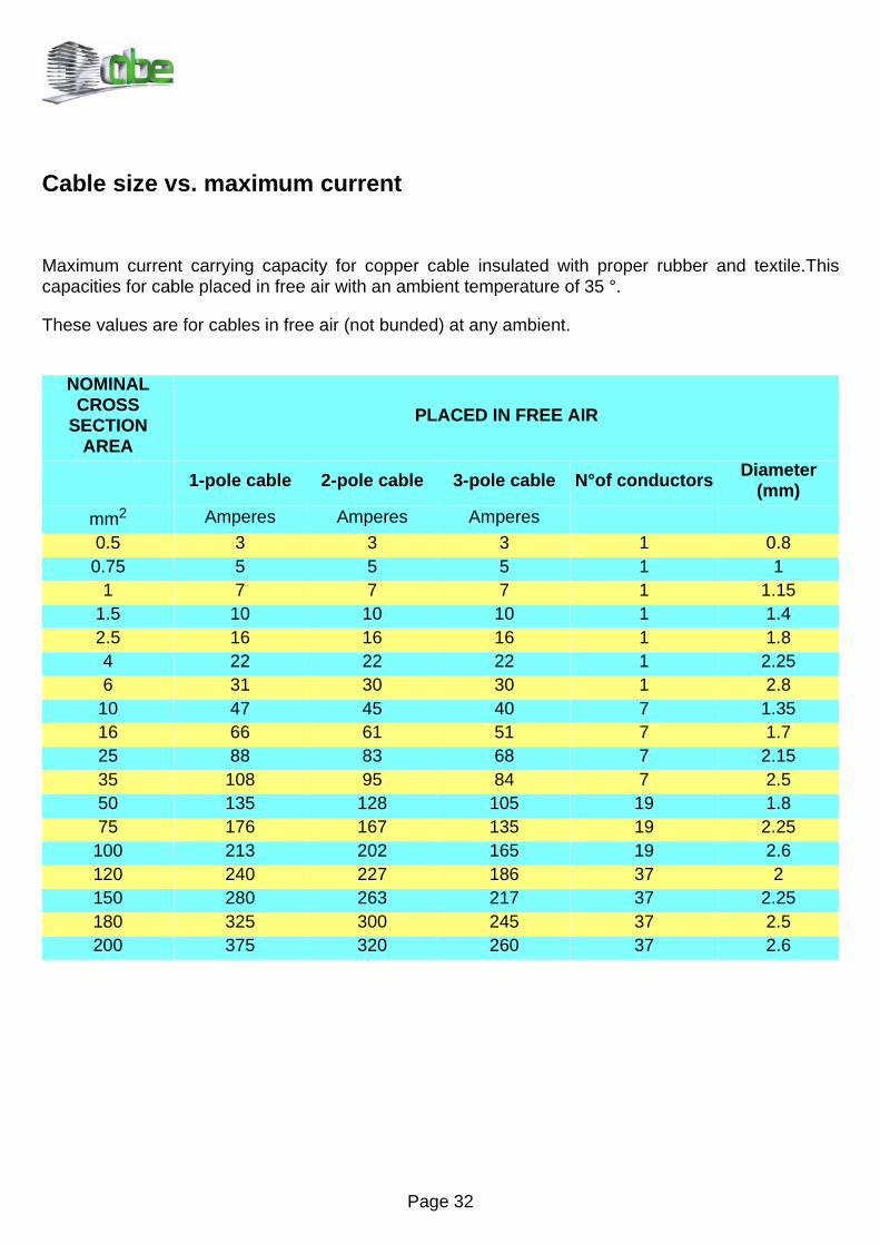
Maximum current carrying capacity for copper cable insulated with proper rubber and textile.Thiscapacities for cable placed in free air with an ambient temperature of 35 °.
These values are for cables in free air (not bunded) at any ambient.
NOMINALCROSS
SECTION AREA
PLACED IN FREE AIR
1-pole cable 2-pole cable 3-pole cable N°of conductors Diameter (mm)
mm2 Amperes Amperes Amperes
0.5 3 3 3 1 0.80.75 5 5 5 1 1
1 7 7 7 1 1.151.5 10 10 10 1 1.42.5 16 16 16 1 1.84 22 22 22 1 2.256 31 30 30 1 2.8
10 47 45 40 7 1.3516 66 61 51 7 1.725 88 83 68 7 2.1535 108 95 84 7 2.550 135 128 105 19 1.875 176 167 135 19 2.25
100 213 202 165 19 2.6120 240 227 186 37 2150 280 263 217 37 2.25180 325 300 245 37 2.5200 375 320 260 37 2.6
Page 33
Conversion factors
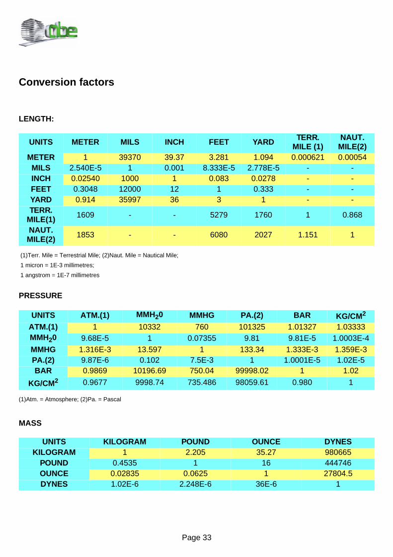
LENGTH:
(1)Terr. Mile = Terrestrial Mile; (2)Naut. Mile = Nautical Mile;
1 micron = 1E-3 millimetres;
1 angstrom = 1E-7 millimetres
PRESSURE
(1)Atm. = Atmosphere; (2)Pa. = Pascal
MASS
UNITS METER MILS INCH FEET YARD TERR. MILE (1)
NAUT. MILE(2)
METER 1 39370 39.37 3.281 1.094 0.000621 0.00054MILS 2.540E-5 1 0.001 8.333E-5 2.778E-5 - -INCH 0.02540 1000 1 0.083 0.0278 - -FEET 0.3048 12000 12 1 0.333 - -YARD 0.914 35997 36 3 1 - -TERR.
MILE(1) 1609 - - 5279 1760 1 0.868
NAUT. MILE(2) 1853 - - 6080 2027 1.151 1
UNITS ATM.(1) MMH20 MMHG PA.(2) BAR KG/CM2
ATM.(1) 1 10332 760 101325 1.01327 1.03333MMH20 9.68E-5 1 0.07355 9.81 9.81E-5 1.0003E-4MMHG 1.316E-3 13.597 1 133.34 1.333E-3 1.359E-3PA.(2) 9.87E-6 0.102 7.5E-3 1 1.0001E-5 1.02E-5BAR 0.9869 10196.69 750.04 99998.02 1 1.02
KG/CM2 0.9677 9998.74 735.486 98059.61 0.980 1
UNITS KILOGRAM POUND OUNCE DYNESKILOGRAM 1 2.205 35.27 980665
POUND 0.4535 1 16 444746OUNCE 0.02835 0.0625 1 27804.5DYNES 1.02E-6 2.248E-6 36E-6 1
Page 34
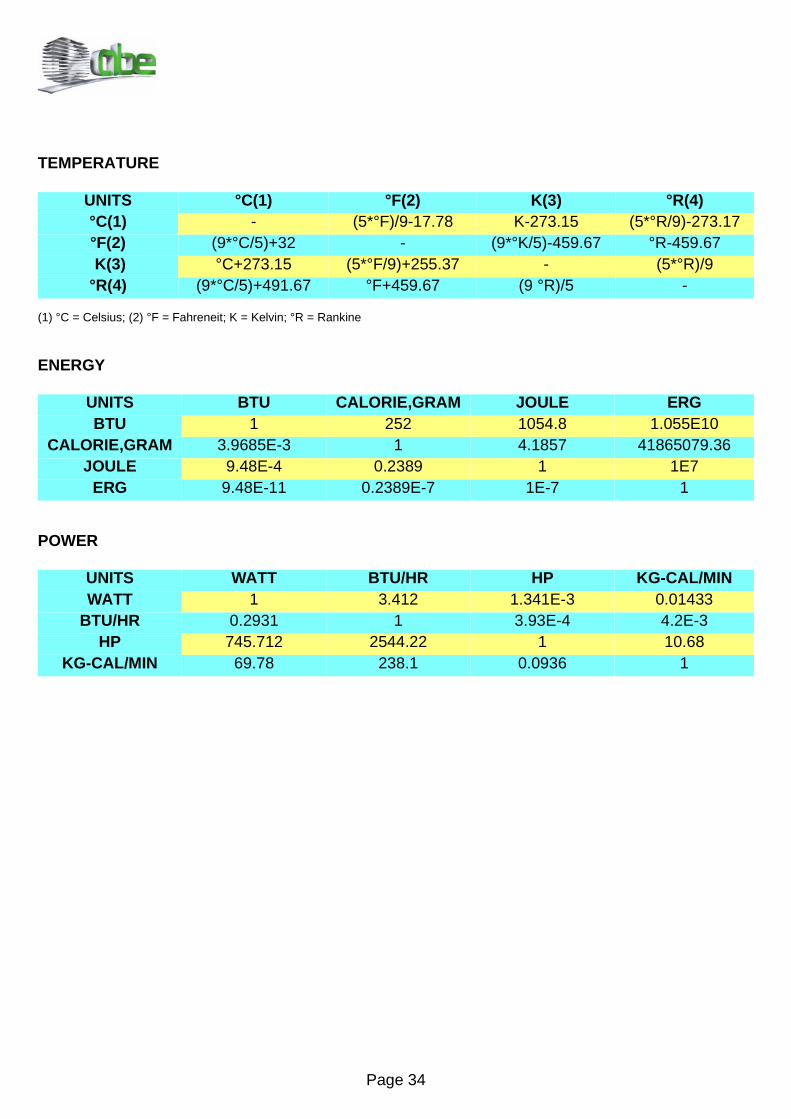
TEMPERATURE
(1) °C = Celsius; (2) °F = Fahreneit; K = Kelvin; °R = Rankine
ENERGY
POWER
UNITS °C(1) °F(2) K(3) °R(4)°C(1) - (5*°F)/9-17.78 K-273.15 (5*°R/9)-273.17°F(2) (9*°C/5)+32 - (9*°K/5)-459.67 °R-459.67 K(3) °C+273.15 (5*°F/9)+255.37 - (5*°R)/9°R(4) (9*°C/5)+491.67 °F+459.67 (9 °R)/5 -
UNITS BTU CALORIE,GRAM JOULE ERGBTU 1 252 1054.8 1.055E10
CALORIE,GRAM 3.9685E-3 1 4.1857 41865079.36JOULE 9.48E-4 0.2389 1 1E7
ERG 9.48E-11 0.2389E-7 1E-7 1
UNITS WATT BTU/HR HP KG-CAL/MINWATT 1 3.412 1.341E-3 0.01433
BTU/HR 0.2931 1 3.93E-4 4.2E-3HP 745.712 2544.22 1 10.68
KG-CAL/MIN 69.78 238.1 0.0936 1
Page 35
Useful formulae
Electrical formulae
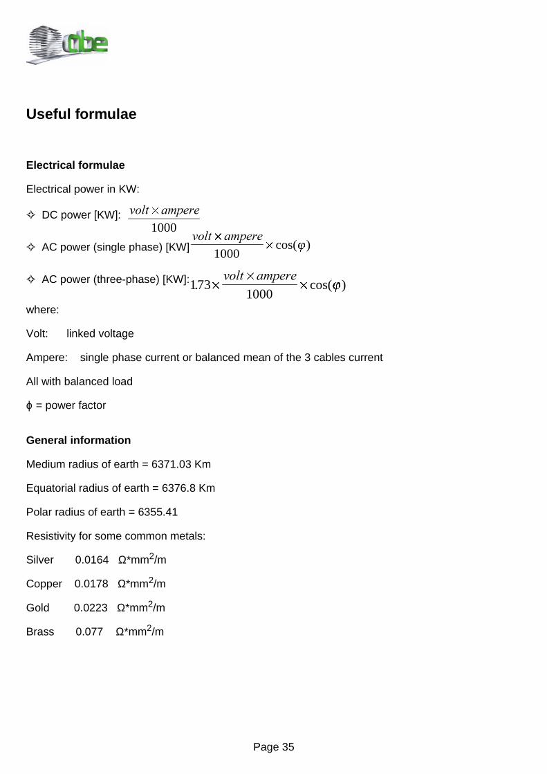
Electrical power in KW:
DC power [KW]:
AC power (single phase) [KW]:
AC power (three-phase) [KW]:
where:
Volt: linked voltage
Ampere: single phase current or balanced mean of the 3 cables current
All with balanced load
ϕ = power factor
General information
Medium radius of earth = 6371.03 Km
Equatorial radius of earth = 6376.8 Km
Polar radius of earth = 6355.41
Resistivity for some common metals:
Silver 0.0164 Ω*mm2/m
Copper 0.0178 Ω*mm2/m
Gold 0.0223 Ω*mm2/m
Brass 0.077 Ω*mm2/m
1731000
. cos( )´
´
´
YROW DPSHUHj
YROW DPSHUH´
´
1000cos( )j
YROW DPSHUH´
1000
Page 36
RF formulae
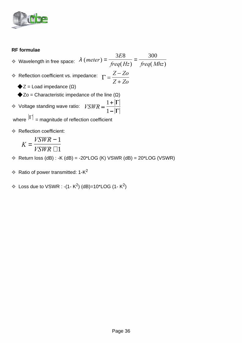
Wavelength in free space:
Reflection coefficient vs. impedance:
Z = Load impedance (Ω)
Zo = Characteristic impedance of the line (Ω)
Voltage standing wave ratio:
where = magnitude of reflection coefficient
Reflection coefficient:
Return loss (dB) : -K (dB) = -20*LOG (K) VSWR (dB) = 20*LOG (VSWR)
Ratio of power transmitted: 1-K2
Loss due to VSWR : -(1- K2) (dB)=10*LOG (1- K2)
G
96:5 =+
-
1
1
G
G
G =-
+
= =R= =R
λ ( )( ) ( )
PHWHU(
IUHT +] IUHT 0K]= =
3 8 300
.96:596:5
=−+
1
1

Page 37
Useful RF calculation
Free space attenuation or path loss between two points:
The calculation is made assuming ideal conditions, ie:
No reflection from terrain,etc
No atmosferic (climatic) attenuation
No obstruction within the first Fresnel ellipsoid
Use of isotropic antennas at either end of the path
[A]: Frequency - Frequency for calculation expressed in MHz
[B]: Distance - Distance between transmitting and receiving antennas, in Km
Free Space Attenuation (path loss) [dB]= 20 x LOG (A) + 20 x LOG (B) + 32.5
6LJQDO⇒)LHOG6WUHQJWK
Signal field strength at the location of the receiving antenna, given the received signal level measuredat the output connector of this antenna, across 50 Ohms.
[A]: Frequency- the frequency of the calculation, expressed in MHz
[B]: Rx antenna gain- the gain of the complete receiving antenna, expressed in dBd (which is the gainin dB referred to a half wavelength dipole) in the actual direction (horizontally and vertically) in whichthe transmitting antenna is situated.
[C]: Received signal(dBuV)- the received signal voltage expressed in dB relative to 1uV (microvolt)measured at the output connector of the receiving antenna across a resistive impedance of 50 Ohms
Field strength [dBuV / m] = 20 102
30020× ×
× ×
−
/RJ
$& % π
Page 38
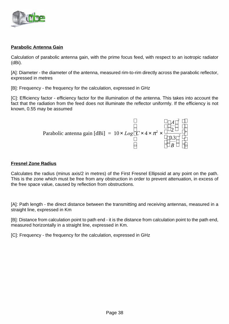
Parabolic Antenna Gain
Calculation of parabolic antenna gain, with the prime focus feed, with respect to an isotropic radiator(dBi).
[A]: Diameter - the diameter of the antenna, measured rim-to-rim directly across the parabolic reflector,expressed in metres
[B]: Frequency - the frequency for the calculation, expressed in GHz
[C]: Efficiency factor - efficiency factor for the illumination of the antenna. This takes into account thefact that the radiation from the feed does not illuminate the reflector uniformly. If the efficiency is notknown, 0.55 may be assumed
Fresnel Zone Radius
Calculates the radius (minus axis/2 in metres) of the First Fresnel Ellipsoid at any point on the path.This is the zone which must be free from any obstruction in order to prevent attenuation, in excess ofthe free space value, caused by reflection from obstructions.
[A]: Path length - the direct distance between the transmitting and receiving antennas, measured in astraight line, expressed in Km
[B]: Distance from calculation point to path end - it is the distance from calculation point to the path end,measured horizontally in a straight line, expressed in Km.
[C]: Frequency - the frequency for the calculation, expressed in GHz
Parabolic antenna gain [dBi] = 10 42
0 32
2
2× × × ×
/RJ &
$
%
π.

Page 39
1st Fresnel zone radius over obstacle:
( )[m] =
0 31000 1000
1
1000
2
.
&% $ %
$
× × × − × ×
×
Page 40
NOTES

Page 41
NOTES
Page 42
NOTES
The material contained in this handbook has been collected from a number of sources.ABE Elettronica S.p.A. accepts no responsability for errors or omissions.