broadr-reach – standard ethernet mediagateway · broadr-reach – standard ethernet....
TRANSCRIPT

BroadR-Reach – Standard Ethernet
MEDIAGATEWAY
User Manual
Version 4.0 February 2016

You can download the latest firmware and documentation for the MediaGateway here:
http://www.technica-engineering.de/produkte/media-gateway/
IMPORTANT: Basic software is provided. Additional functionalities can be activated through this email:

Page 1 of 66
Index INDEX ............................................................................................................................................................................. 1
FEATURE LIST .................................................................................................................................................................. 3
WARRANTY AND SAFETY INFORMATION ........................................................................................................................ 5
PINNING ......................................................................................................................................................................... 6
POWER CONNECTOR (TOP LEFT) ................................................................................................................................................. 7 SWITCH CONNECTORS .............................................................................................................................................................. 8 RJ45 ETHERNET CONNECTORS ................................................................................................................................................... 8 SFP SLOT ............................................................................................................................................................................... 8
STATUS LEDS AND PUSHBUTTON .................................................................................................................................... 9
CONFIGURATION WEBSITE ............................................................................................................................................ 10
WEBSITE HOME .................................................................................................................................................................... 11 SYSTEM INFORMATION TAB ..................................................................................................................................................... 11 CONTROL PANEL TAB ............................................................................................................................................................. 12 SWITCH STATUS TAB .............................................................................................................................................................. 13
Global Configuration .................................................................................................................................................... 13 ARL Table status ........................................................................................................................................................... 14 Ports ............................................................................................................................................................................. 15
Ethernet Port .............................................................................................................................................................................. 16 BroadR-Reach Port ...................................................................................................................................................................... 17
BroadR-Reach Test Modes ..................................................................................................................................................... 18 SFP Port ....................................................................................................................................................................................... 19
ETHERNET CAN GATEWAY (EXTRA LICENSE NEEDED) .................................................................................................... 21
ETHERNET CAN GATEWAY CONFIGURATION (UDP MODE): .......................................................................................................... 21 ETHERNET CAN GATEWAY CONFIGURATION (RAW MODE): .......................................................................................................... 22 ETHERNET CAN GATEWAY SYNC FRAMES .................................................................................................................................. 24 STRUCTURE OF A CAN/ETHERNET PACKET .................................................................................................................................. 25 STRUCTURE OF A TIMESTAMP PACKET ........................................................................................................................................ 25 STRUCTURE OF A UDP PACKET / RAW FRAME: ........................................................................................................................... 26
ETHERNET 2 CAN FILTERING (EXTRA LICENSE NEEDED) ................................................................................................. 27
FUNCTIONALITY DESCRIPTION .................................................................................................................................................. 27 TECHNICAL FEATURES ............................................................................................................................................................. 27 CONFIGURATION ................................................................................................................................................................... 27
General Parameters ..................................................................................................................................................... 28 SOME/IP parameters .................................................................................................................................................... 29 CAN parameters ........................................................................................................................................................... 31
FORMAT OF THE CAN DATA MESSAGE: ..................................................................................................................................... 32 Format of the CAN Error Message:............................................................................................................................... 32
SOME/IP-SD SUBSCRIBE ....................................................................................................................................................... 33 GENERAL PARAMETERS........................................................................................................................................................... 34 SUBSCRIBE PARAMETERS ......................................................................................................................................................... 34 VLAN CONFIGURATION EXAMPLE ............................................................................................................................................ 35 PARAMETER EXAMPLE ............................................................................................................................................................ 36
802.1AS......................................................................................................................................................................... 38
PROTOCOL ........................................................................................................................................................................... 38 Transport of time-synchronization information ........................................................................................................... 38 Propagation delay measurement ................................................................................................................................. 39
USING 802.1 AS .................................................................................................................................................................. 40 LIMITATIONS ........................................................................................................................................................................ 41

Page 2 of 66
VLAN CONFIGURATION ................................................................................................................................................. 42
VLAN BASICS ....................................................................................................................................................................... 42 PORT-BASED VLAN ............................................................................................................................................................... 42 SINGLE TAGGING - IEEE 802.1Q (VLAN) MODE ......................................................................................................................... 43
Single Tagging Example ............................................................................................................................................... 45 Setting VLAN for MediaGateway´s webpage. ............................................................................................................................. 45
DOUBLE TAGGING - IEEE 802.1Q (VLAN) MODE ....................................................................................................................... 47 Double Tagging Example.............................................................................................................................................. 50
MEDIAGATEWAY REMOTE CONTROL ............................................................................................................................ 51
RESET DEVICE ....................................................................................................................................................................... 52 IMPORT CONFIGURATION ........................................................................................................................................................ 52 EXPORT CONFIG .................................................................................................................................................................... 53 DYNAMIC CONFIG ................................................................................................................................................................. 53 CHECK STATUS ...................................................................................................................................................................... 54 SET WAKEUP LINE STATUS ...................................................................................................................................................... 54 GET WAKEUP LINE STATUS ..................................................................................................................................................... 54 PORT ENABLE (OABR) ........................................................................................................................................................... 55 PORT MASTER/SLAVE (OABR) ................................................................................................................................................ 55 RESET TO DEFAULT ................................................................................................................................................................. 55
HARDWARE VARIANTS .................................................................................................................................................. 56
BROADR-REACH ANALOG FILTER: ............................................................................................................................................ 56 DEBUG CONNECTOR ............................................................................................................................................................... 56 STARTUP TIME ...................................................................................................................................................................... 57
MediaSwitch (all Versions), MediaGateway Version up to 2.1: ......................................................................................... 57
BOOTLOADER UPDATE .................................................................................................................................................. 58
APPLICATION FIRMWARE UPDATE ................................................................................................................................ 56
FREQUENTLY ASKED QUESTIONS – FAQ ......................................................................................................................... 58
CONTACT ...................................................................................................................................................................... 59
Page 3 of 66
Feature List The Technica Engineering MediaGateway has the following basic features:
12 Ports Broadcom BroadR-Reach 100 MBit/s Fullduplex on a single unshielded twisted pair
3 Ports Gigabit Ethernet 10/100/1000 BaseTX Fullduplex
1 Port Gigabit Ethernet SFP module socket
Broadcom BroadR-Reach Technology Tyco MQS Connectors for BroadR-Reach and Power Supply Webserver for easy configuration:
o Master / Slave o Port Mirroring o VLAN Tagging o Port Status Display
Import and Export of Configurations WakeUp functionality CAN, LIN and FlexRay interfaces (requires customer specific software) Power output for attached devices: VBAT max. 1,2 Ampere in total (Fused) 19 Status LEDs Possibility to reset to default settings by pushbutton Robust steel case
Power requirement: 7 to 16 Volt DC (nominal 12 Volt DC)
Power consumption: 7 to 12 Watt
Size: 195 x 143 x 33 mm
Weight: 0,77 kg
International Protection: IP 2 0
Operating Temperature: -40 to +80 °Celsius

Page 5 of 60
Warranty and Safety Information
Before operating the device, read this manual thoroughly and retain it for your reference. You can download the latest firmware and documentation for the MediaGateway here: http://www.technica-engineering.de/MediaGateway
Use the device only as described in this manual. Use only in dry conditions. Do not apply power to a damaged device.
Do not open the device. Otherwise warranty will be lost.
This device is designed for engineering purpose only. Special care has to be taken for operation. Do not use this device in a series production car. As this device is likely to be used under rough conditions, warranty is limited to 1 year. Manufacturer liability for damage caused by using the device is excluded.

Page 6 of 60
Pinning The pinning of the ECU connectors is listed on the label on top of the device. The Tyco Electronics (TE) Micro Quad Lock System (MQS) is used.
Name Type Part Number
Tyco, MQS Abdeckkappe 2x9 Pol, black 1-967416-1 Alternatively 1-1355350-1
Tyco, MQS Abdeckkappe 2x9 Pol, blue 3-967416-1 Tyco, MQS Buchsenge-
häuse 2x9 Pol 965778-1
Alternatively 962108-2 Tyco crimp contact 928999-1
Note: You can use the official Tyco tool for these crimp contacts. A cheap variant is the crimp tool for “PSK” contacts.
Page 7 of 60
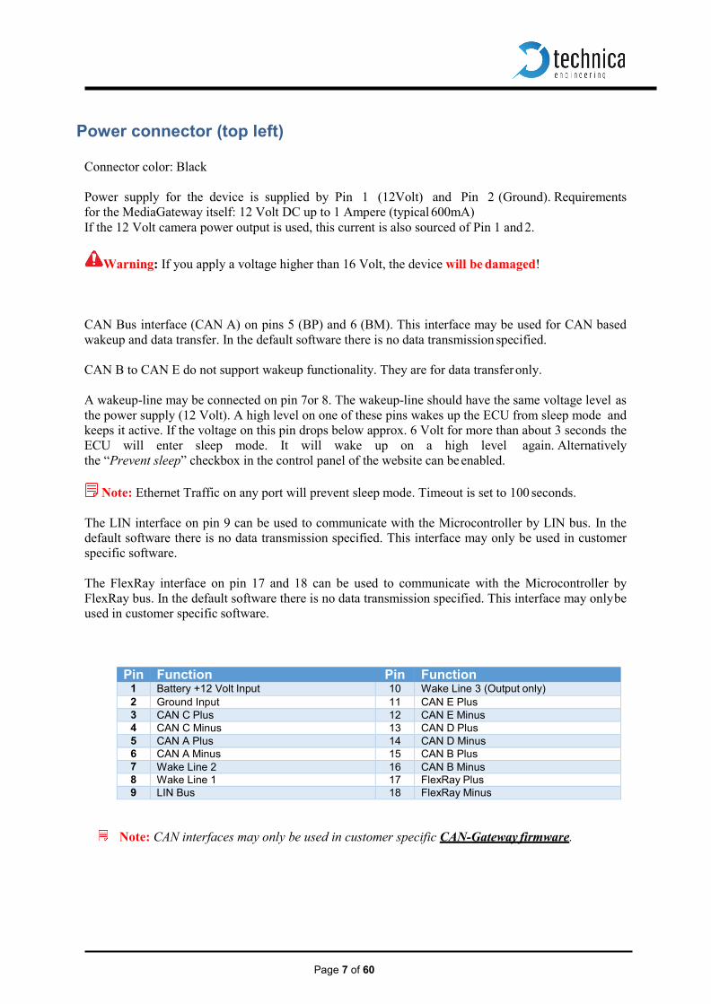
Power connector (top left)
Connector color: Black
Power supply for the device is supplied by Pin 1 (12Volt) and Pin 2 (Ground). Requirements for the MediaGateway itself: 12 Volt DC up to 1 Ampere (typical 600mA) If the 12 Volt camera power output is used, this current is also sourced of Pin 1 and 2.
Warning: If you apply a voltage higher than 16 Volt, the device will be damaged!
CAN Bus interface (CAN A) on pins 5 (BP) and 6 (BM). This interface may be used for CAN based wakeup and data transfer. In the default software there is no data transmission specified.
CAN B to CAN E do not support wakeup functionality. They are for data transfer only.
A wakeup-line may be connected on pin 7or 8. The wakeup-line should have the same voltage level as the power supply (12 Volt). A high level on one of these pins wakes up the ECU from sleep mode and keeps it active. If the voltage on this pin drops below approx. 6 Volt for more than about 3 seconds the ECU will enter sleep mode. It will wake up on a high level again. Alternatively the “Prevent sleep” checkbox in the control panel of the website can be enabled.
Note: Ethernet Traffic on any port will prevent sleep mode. Timeout is set to 100 seconds.
The LIN interface on pin 9 can be used to communicate with the Microcontroller by LIN bus. In the default software there is no data transmission specified. This interface may only be used in customer specific software.
The FlexRay interface on pin 17 and 18 can be used to communicate with the Microcontroller by FlexRay bus. In the default software there is no data transmission specified. This interface may only be used in customer specific software.
Pin Function Pin Function 1 Battery +12 Volt Input 10 Wake Line 3 (Output only) 2 Ground Input 11 CAN E Plus 3 CAN C Plus 12 CAN E Minus 4 CAN C Minus 13 CAN D Plus 5 CAN A Plus 14 CAN D Minus 6 CAN A Minus 15 CAN B Plus 7 Wake Line 2 16 CAN B Minus 8 Wake Line 1 17 FlexRay Plus 9 LIN Bus 18 FlexRay Minus
Note: CAN interfaces may only be used in customer specific CAN-Gateway firmware.
Page 8 of 60
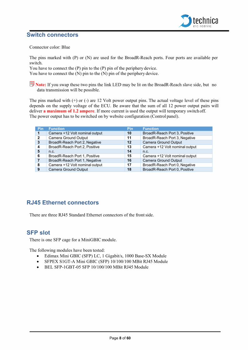
Switch connectors
Connector color: Blue
The pins marked with (P) or (N) are used for the BroadR-Reach ports. Four ports are available per switch. You have to connect the (P) pin to the (P) pin of the periphery device. You have to connect the (N) pin to the (N) pin of the periphery device.
Note: If you swap these two pins the link LED may be lit on the BroadR-Reach slave side, but no
data transmission will be possible.
The pins marked with (+) or (-) are 12 Volt power output pins. The actual voltage level of these pins depends on the supply voltage of the ECU. Be aware that the sum of all 12 power output pairs will deliver a maximum of 1.2 ampere. If more current is used the output will temporary switch off. The power output has to be switched on by website configuration (Control panel).
Pin Function Pin Function 1 Camera +12 Volt nominal output 10 BroadR-Reach Port 3, Positive 2 Camera Ground Output 11 BroadR-Reach Port 3, Negative 3 BroadR-Reach Port 2, Negative 12 Camera Ground Output 4 BroadR-Reach Port 2, Positive 13 Camera +12 Volt nominal output 5 n.c. 14 n.c. 6 BroadR-Reach Port 1, Positive 15 Camera +12 Volt nominal output 7 BroadR-Reach Port 1, Negative 16 Camera Ground Output 8 Camera +12 Volt nominal output 17 BroadR-Reach Port 0, Negative 9 Camera Ground Output 18 BroadR-Reach Port 0, Positive
RJ45 Ethernet connectors
There are three RJ45 Standard Ethernet connectors of the front side.
SFP slot There is one SFP cage for a MiniGBIC module.
The following modules have been tested:
• Edimax Mini GBIC (SFP) LC, 1 Gigabit/s, 1000 Base-SX Module • SFPEX S1GT-A Mini GBIC (SFP) 10/100/100 MBit RJ45 Module • BEL SFP-1GBT-05 SFP 10/100/100 MBit RJ45 Module
Page 9 of 60
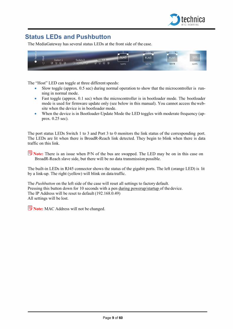
Status LEDs and Pushbutton The MediaGateway has several status LEDs at the front side of the case.
The “Host” LED can toggle at three different speeds: • Slow toggle (approx. 0.5 sec) during normal operation to show that the microcontroller is run-
ning in normal mode. • Fast toggle (approx. 0.1 sec) when the microcontroller is in bootloader mode. The bootloader
mode is used for firmware update only (see below in this manual). You cannot access the web- site when the device is in bootloader mode.
• When the device is in Bootloader-Update Mode the LED toggles with moderate frequency (ap- prox. 0.25 sec).
The port status LEDs Switch 1 to 3 and Port 3 to 0 monitors the link status of the corresponding port. The LEDs are lit when there is BroadR-Reach link detected. They begin to blink when there is data traffic on this link.
Note: There is an issue when P/N of the bus are swapped. The LED may be on in this case on
BroadR-Reach slave side, but there will be no data transmission possible.
The built-in LEDs in RJ45 connector shows the status of the gigabit ports. The left (orange LED) is lit by a link-up. The right (yellow) will blink on data traffic.
The Pushbutton on the left side of the case will reset all settings to factory default. Pressing this button down for 10 seconds with a pen during powerup/startup of the device. The IP Address will be reset to default (192.168.0.49) All settings will be lost.
Note: MAC Address will not be changed.

Page 10 of 60
Configuration Website You can access the configuration website with a standard web browser.
Note: Firefox is recommended, Chrome is not recommended.
Connect your PC to a RJ45 connector. The default IP address of the device is 192.168.0.49 and subnet mask 255.255.255.0 If IP address has been changed, you can reset it to default as described in chapter 3 of this manual.
For example set the configuration PC to IP address 192.168.0.100 and subnet mask to 255.255.255.0

Page 11 of 60
Website Home
Warning: If there is a lot of broadcast traffic on the switch, the host microcontroller may be jammed. You cannot access the website in this case. Please use VLAN configuration to forward only relevant messages to the microcontroller.
With the first access to the website you will get the home screen. Please select one of the tabs for further configuration.
System Information Tab
On the tab „System Information“ some status information about the device is displayed. You can check the version number of the application firmware and the bootloader or the unique MAC adress of the device. The version number registers of the switch and phy chips are displayed for information only. Up to version 4.1.12 it also shows the UUID that the user will need in order to activate extra features. You can see wich functionality is Unlocked. The MAC adress should be the same as on the label on the bottom of the device.
You can change the IP adress of the host microcontroller (Webserver) here. If you want to use multiple devices in one network, you have to configure a unique IP adress for each device here.

Page 12 of 60
Note: If someone has changed the IP address you can reset it to default as described in chapter 4 of this manual.
Control Panel Tab
On the „Control Panel“ tab you can soft-reset (restart) the system.
Also you can import or export the configuration settings of the device to a file (*.cfg) on a computer connected to the RJ45 Port. You have to restart the device for usage of the new configuration.
You can reset the configuration settings to default. All the configuration stored will be revert to its defaults values. IP address will be not modified.
The camera power output pins are disabled by default. You have to activate them by setting the checkbox in the Control Panel.
If you do not want to use a WakeUp line or the CAN bus wake-up, you can enable the “Prevent sleep” checkbox (default). This will keep the device running without entering the sleep mode.
If you enable “Diagnose Service”1 functionality, MediaGateway will send periodically status infor- mation about its state. For example, transmitted and dropped frame counters. More details about the format of these frames see the Fibex File (and .pdf description) in the firmware release files. Fibex File can be loaded ANDi Tool in order to dissect the frame contents.
In order to activate extra features (CAN Gateway, BMW Extra Functions), the user should contact us to order an activation key. See Contact Tab.
1 Note: “Watchover”or “Diagnose Service” is available from firmware version 4.1.2

Page 13 of 60
Switch Status Tab
The main configuration of the switch is done in the „Switch Status“ tab. Here you can configure details about each port and get some status information about the ports and switch states.
On the left side of the page you can see an overview of all available ports. A blue bar at the side of a port label indicates an active link (On the Cascade SFP port there is no link indication).
Global Configuration
When you click on „Switch Status“ tab and no port or switch is still selected, Global configuration will appear. Here it is possible to activate Single or Double tagging2.
On the right side details of the selected port are displayed. If you load a configuration file, these settings are set automatically. If you do not have a configuration file, you have to set these manually for each used port.
2 Note: For more information about VLAN configuration in chapter 6.

Page 14 of 60
ARL Table status
When you click on the switch label the Address Resoultion Table of this switch will be displayed for your information. ARL table is filled dynamically. It shows the learned MAC adresses, VLAN ID, Forward port and Age Bit.
Note: Age Bit indicates if ARL entry is active.
In next example we see that Switch 1 has learned two ARL Entries:
1) MAC Address 00:50:C2:E4:34:E5 is reachable throught port 4 using VLAN 0x049. 2) MAC Address 00:24:9B:06:7B:97 is reachable throught port 5 using VLAN 0x049
NOTE: When IEEE 802.1q (VLAN) mode is disabled, VLAN will be 0x000.
Page 15 of 60
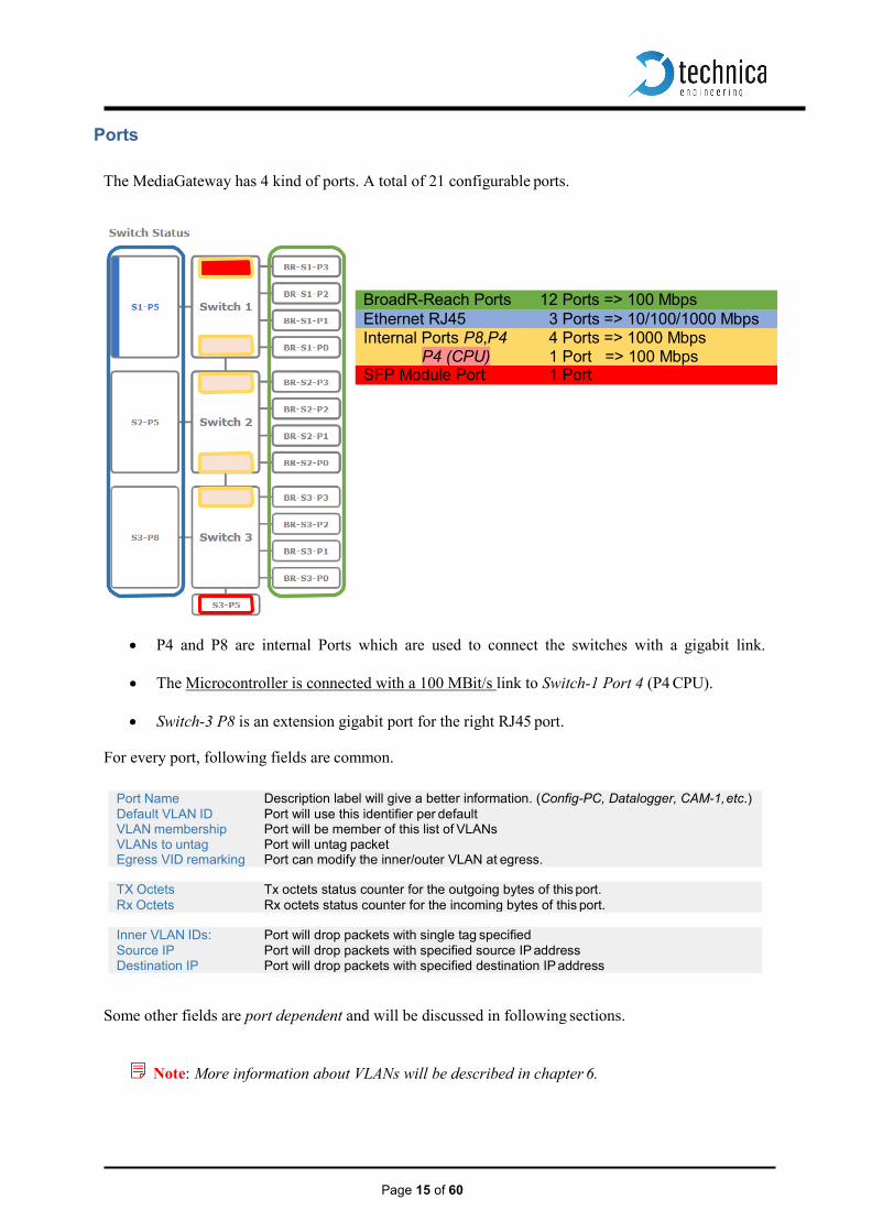
Ports The MediaGateway has 4 kind of ports. A total of 21 configurable ports.
• P4 and P8 are internal Ports which are used to connect the switches with a gigabit link.
• The Microcontroller is connected with a 100 MBit/s link to Switch-1 Port 4 (P4 CPU).
• Switch-3 P8 is an extension gigabit port for the right RJ45 port.
For every port, following fields are common.
Port Name Description label will give a better information. (Config-PC, Datalogger, CAM-1, etc.) Default VLAN ID Port will use this identifier per default VLAN membership Port will be member of this list of VLANs VLANs to untag Port will untag packet Egress VID remarking Port can modify the inner/outer VLAN at egress.
TX Octets Tx octets status counter for the outgoing bytes of this port. Rx Octets Rx octets status counter for the incoming bytes of this port.
Inner VLAN IDs: Port will drop packets with single tag specified Source IP Port will drop packets with specified source IP address Destination IP Port will drop packets with specified destination IP address
Some other fields are port dependent and will be discussed in following sections.
Note: More information about VLANs will be described in chapter 6.
BroadR-Reach Ports 12 Ports => 100 Mbps Ethernet RJ45 3 Ports => 10/100/1000 Mbps Internal Ports P8,P4
P4 (CPU) 4 Ports => 1000 Mbps 1 Port => 100 Mbps
SFP Module Port 1 Port

Page 16 of 60
Ethernet Port
Besides the common fields to all ports, Ethernet ports allows the user to select link speed. • Mirroring: The “Mirroring” feature of a current port copies all incoming traffic from the checked
port (BroadR-Reach or internal port) to this “capture” port.
Note: Only one port per switch can be the “capture” port! If another port (internal P4 or P8) is using mirroring, Ethernet port cannot use mirroring.
• Speed: It is possible to set the speed of an Ethernet port through auto-negotiation. Following table
shows the available options:
Auto-negotiation all Capable Duplex and Speed auto-detection Auto – Only 10 Mbps Capable Duplex auto-detection – 10 Mbps advertisement Auto – Only 100 Mbps Capable Duplex auto-detection – 100 Mbps adv. Auto – Only 1000 Mbps Capable Duplex auto-detection – 1000 Mbps adv.
• Detected speed: Show result of link negotiation. Speed and half/full duplex.

Page 17 of 60
BroadR-Reach Port
Besides the common fields to all ports, BroadR-Reach ports allows the user to: • Enable port: With this checkbox the BroadR-Reach ports can be enabled or disabled completely.
Note: If port is disabled and cable is still connected, LED status for this port will be lit but no
data is sent or received. Webpage will show no blue bar for this port . • BroadR-Reach mode: On each BroadR-Reach link there has to be one master and one slave device.
Please set the “BroadR-Reach mode” to the opposite of what the device is set you have connected to this port.
• Output level: The “Output Level” is the amplitude level of the BroadR-Reach signal. You can set
Full level (Fullout = default) or half amplitude.
Note: Both devices of one BroadR-Reach link have to use the same level. Otherwise you will get an instable link. FullOut Level is always recommended.
• Link Quality: The “link quality” is an indicator about the signal integrity of the BroadR-Reach link
on this port. 1 = Poor , 5 = Excellent

Page 18 of 60
BroadR-Reach Test Modes
For BroadR-Reach Ports it is possible to set a BroadR-Reach Physical Layer Test Mode. There are five test modes defined in the BoradR-Reach Specification to check the compliance of a port.
Warning: When a test mode has been selected there is no communication possible for this port.
Note: For compliance testing an oscilloscope with special test software is necessary.
Page 19 of 60
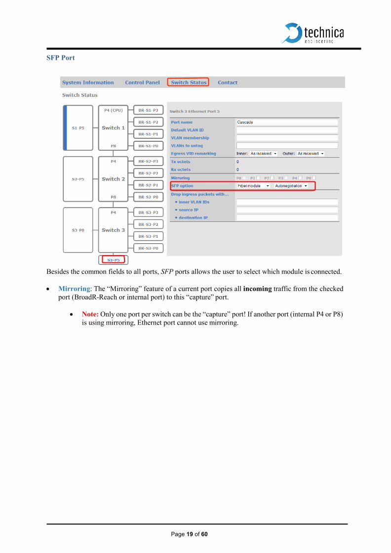
SFP Port
Besides the common fields to all ports, SFP ports allows the user to select which module is connected. • Mirroring: The “Mirroring” feature of a current port copies all incoming traffic from the checked
port (BroadR-Reach or internal port) to this “capture” port.
• Note: Only one port per switch can be the “capture” port! If another port (internal P4 or P8) is using mirroring, Ethernet port cannot use mirroring.

Page 20 of 60
• SFP option: You have the choice of different modules.
1. The SFP Port can be set to “Fiber” if you care using a SFP MiniGBIC Fiber module.
2. Use “RJ45” for copper modules.
3. Use HSD for old MediaSwitches which have an HSD connector instead of an SFP slot.
The SFP module is not part of standard delivery.
The SFPEX 10/100/1000 Modules have been tested in this device.
The Bel SFP-1GBT-05 Copper Modules 10/100/1000Base-T have been tested in this device.
The Edimax Mini GBIC (SFP) LC, 1Gigabit/s, 1000 Base-SX Modules have been tested in this device.

Page 21 of 60
Ethernet CAN Gateway (extra license needed)
The Ethernet CAN gateway can be configured using a web page. Its properties can be set on the “CAN Functions” page. The following picture shows the available settings.
There are four modes of communications (UDP, RAW, Speed RAW and Extrem RAW). The switching between them is done using the radio button Communication Mode.
User can use CAN Parameters table to set CAN Channel speed and set a list of CAN IDs to be filtered.
• Speed: CAN channel speed can be set to: 125 Kbps, 500 Kbps or 1000 Kbps. • CANID Filtering: Can be activated for each channel independently.
Ethernet CAN Gateway Configuration (UDP mode):
Here the Ethernet CAN gateway can be configured by setting target IP Address and the port of the UDP packets. Non-valid entries will not be accepted and will be replaced by default values. If either the target IP address or the port has the default value set, the Ethernet CAN Gateway will be disabled.

Page 22 of 60
• Destination IP address Here the target IP address for the UDP packets can be entered in dot-decimal notation. The default IP address is 255.255.255.255.
• rxPort Here the target port of the UDP packets can be set. Valid port numbers go from 1 to 65535.
Ethernet CAN Gateway Configuration (RAW mode):
Here the Ethernet CAN gateway can be configured by setting target MAC Address and the EtherType of the RAW packets. Non-valid entries will not be accepted and will be replaced by default values. If either the target MAC address or the EtherType has the default value set, the Ethernet CAN Gateway will be disabled.

Page 23 of 60
• Target MAC Address Target MAC address must respect the usual format (a sequence of
six hexadecimal numbers having two bytes size each, separated by a two points delimiter) xx:xx:xx:xx:xx:xx. Note that entering Broadcast MAC address “0xFFFFFFFFFFFF” as Target MAC ad- dress will cause sending time stamps frames to be disabled.
• Ethertype EtherType is a two bytes hexadecimal number. EtherType field can accept any value between 0 and FFFF.

Page 24 of 60
6.1 Ethernet CAN Gateway Configuration (Speed and Extreme RAW)
• Speed RAW is faster as normal RAW. Incoming Ethernet-RAW frames are fixed to Ethernet Type: 0x1986
• Extreme RAW is the fastest mode. It is only accepting RAW Frames with EthernetType 0x1987
Ethernet CAN Gateway Sync Frames Here several parameters concerning the sync frames can be set. Non-valid entries will not be accepted and will be replaced by default values. If one of these fields has the default value set, the generation of the sync frames will be disabled.
• CAN BUS In this field the target bus for the CAN sync frames can be set. It is a number
between 1 and 6. The default CAN bus number is 0.
• CAN ID (hex) The CAN ID of the sync frames as a hexadecimal number. For standard frame format the ID is between 0 and 7ff. Default CAN ID is FFFFFFFFFF.
• Cycle time (in 10ms steps)
The cycle time of the sync frames in 10 millisecond steps. A setting of 10 means a cycle time of 100ms. The default setting is 0, meaning the generation of sync frames is disabled.

Page 25 of 60
Structure of a CAN/Ethernet packet
The following picture shows the structure of a CAN packet that is sent as a UDP packet/RAW frame. B0 B1 B2 B3 B4 B5 B6 B7
UDP Packet/RAW frame containing CAN Packet
0 version
CAN Channel
ID
ID
ID
ID
ID type
frame type
8 DLC D0 D1 D2 D3 D4 D5 D6
16 D7
Field Size Description version uint8 Version of the CAN/Ethernet Packet type. It is always 1 for this type
of CAN/Ethernet packet. CAN channel
uint8 Number between 1 and 4 for the channel CAN of this packet.
ID uint32 CAN ID for base or extended frame format. ID type uint8 0 for 11 Bit standard ID
1 for 29 Bit extended ID frame type uint8 0 for CAN data frame
1 for CAN remote transmission request DLC uint8 Payload length of the CAN packet. D0 … D7 1 to 8 × uint8 Payload
Structure of a timestamp packet Timestamp packets that are sent on Ethernet use nearly the same structure as CAN/Ethernet packets. The frame type is always 0 and the payload length is always 8. The CAN ID can be set in the web interfaceFehler! Verweisquelle konnte nicht gefunden werden.. The payload T0…T8 contains the actual timestamp with 1µs accuracy. It is transmitted in big endian format. A payload of 00 00 00 00 00 00 00 01 means a timestamp containing the time 1µs.
B0 B1 B2 B3 B4 B5 B6 B7
UDP Packet /RAW frame containing Time Stamp Information
0 1 CAN
Channel ID ID ID ID ID type 0 8 8 T0 T1 T2 T3 T4 T5 T6 16 T7

Page 26 of 60
Structure of a UDP packet / RAW frame:
• CAN packet packed in a UDP packet :
Ethernet Header
(14 Bytes)
IP Header (20 Bytes)
Destination IP Address (4 Bytes)
UDP Header
(8 Bytes) Destination Port
(2 Bytes)
Payload (CAN packet)
(17 Bytes )
• CAN packet packed in RAW frame:
Destination MAC
(6 Bytes)
Source MAC
(6 Bytes)
EtherType (2 Bytes)
Payload (CAN packet)
(17 Bytes )
Note: Fields in red color are settable through the website (Ethernet CAN Gateway Configura- tion).
UDP Packet size=59
RAW Frame Size=31
Page 27 of 60
Ethernet 2 CAN Filtering (extra license needed) Ethernet 2 CAN Filtering as well as SOME-IP-SD Subscribe are part of BMW Extra Functionality.
Functionality Description The Ethernet2CAN Filtering function allows the user to send some of the Ethernet packets that the MediaGateway is currently routing, as a standard CAN message with a configurable CAN ID. This functionality doesn´t affect the configured routing of the Ethernet packet through the MediaGateway. For this reason the packets that match with the preconfigured Filter will be sent as CAN message, but also will continue its normal path to the destination ports. The fact that the normal routing of the packets won´t be modified with this functionality, makes the Ethernet2CAN Filtering a very useful extra functionality for the MediaGateway. Here are some example use cases that could make this functionality interesting for your application:
• Each time that an Ethernet packet matches with the filter, a CAN Packet will be generated. If there is not a Mirroring port enabled on the system or if there is not an available Ethernet Port to use this function, the Ethernet2CAN Filtering allows recognizing easily if the desired packet is flowing through the system.
• If the frequency between Ethernet packets is not too high, this functionality can be used to measure time distributions of the Ethernet packets.
• A CAN packet will be generated as a response of the reception of a predefined Ethernet Packet. This CAN Packet could be used as a trigger to initiate another desired action.
Technical Features • Possibility to configure up to two independent IP Filters. Each filter can be configured for a
Source IP, a destination IP (optional) and a specified Outer VLAN. • Possibility to configure from 1 to 5 SomeIP Filters. This makes it possible to filter according
to 5 different SomeIP Packets, configuring a desired ServiceID, an Event or MethodID for each packet.
• Configurable selection of the bytes of the Ethernet Payload that will be sent through CAN. • Possibility to send more than 8 bytes of the Ethernet packet, using multiple CAN Packets. • Configurable CAN ID for the CAN message. Possibility to configure a different CAN ID for
each of the 5 possible SomeIP Filters. • Configurable CAN Error ID message, used to indicate an overload of the system.
Configuration
All the parameters regarding to the configuration of the Ethernet2CAN Filtering are placed on the tab “Ethernet CAN Filtering” in the webpage of the MediaGateway. On this tab it is possible also to get information about the statistics of the current configuration, for example, the number of packets received that matches with the configured rules. The configuration Parameters are divided in three different groups: General Parameters, SOME/IP Pa- rameters and CAN Parameters. • Note: If any configuration change is performed, it has to be saved and the MediaGateway has
to be restarted before the newly introduced parameters are used.

Page 28 of 60
General Parameters
The general parameters are used to enable and configure a maximum of 2 Filters, which are used to define the packets that the processor will receive, but that normally it should not receive. The general parameters contain three parameters, related with IP protocol (IP source and destination) and the topology of the connections in the MediaGateway, defined through the Outer VLAN Tag. To enable the Ethernet2CAN Filtering it is necessary that at least one of the two filters are enabled with at least a correctly introduced SourceIP and Outer VLAN. The parameter “Destination IP” is an optional parameter. It could be used to reduce the number of the matching results.
• SourceIP contains the source IP Address of the packets that should be captured. • DestinationIP contains the destination IP Address of the packets that should be captured. • OuterVLAN (hexadecimal format): In the MediaGateway Outer VLAN Tagging is used to
route the received packets (normally single tagged) from source to destination port. Based on the idea that each port or group of ports will have a different Outer VLAN, this parameter is used to define the physical port of the MediaGateway whereby the packet will go inside the board. In the case that packets with the same source and destination IP come inside the MediaGate- way, it can be used to define only one connection where the packet will be captured.
As all the packets that match the filter will reach the Processor and be processed (or discarded later), the numbers of IP filters is limited to two. The number of packets of each filter received on the processor, matching with the first or second group of parameters introduced (general parameters), are shown in the webpage on the next table. This Infor- mation can be used to recognize if the filter was correctly configured and if packets matching the pre- defined filter are being received.
Although the number of different IP&VLAN filters where limited to a maximum of two filters, an over- load of the processor could happen, when the incoming traffic excesses the maximum that the processor is able to process. It is responsibility of the user ensuring that the processor will not be overloaded due to an extremely high incoming traffic, which would lead to the loss of frames or problems to access the webpage. The webpage is already configured to show dynamically if the parameters being introduced by the user are in the expected format. Red indicates that the value is incorrect or the format differs from the ex- pected. Green indicates that the value matches the expected format for this field. Although the param- eters introduced were valid, if the received packets don´t match with any of the predefined SOME/IP Filters, the CAN Packets won´t be sent. To help the user to detect and correct this problem, some statistics are shown in the webpage. The packet reception buffers used for big packets (>128 Bytes) and for small packets (<128 Bytes), the total size of the memory used for each one of the two types and the handling of these buffers are different according to the size of the packet. This reason makes that an overload of the processor could be caused by a lack of resources for small or for big packets independently.

Page 29 of 60
The two first columns reflect indirectly the free memory for reception still available, the concept differs for big and for small packets. The third column of the next table (Dropping Big Packets/ Dropped Small Packets) reflects the state of the reception buffers of the processor.
• For big Packets (>128 Bytes): If the indicator for big packets in third column shows a “Yes” packets are currently being lost.
• For small Packets (<128 Bytes): The number of packets loss due a lack of resources for a small packet will be direct reflecting on this column of the table. As far as this value remains in 0, small packets aren´t lost.
In case that the webpage was not accessible due this huge incoming traffic, a CAN Packet with the preconfigured CAN Error ID will be send.
SOME/IP parameters The SOME/IP parameters are used to enable and configure a maximum of 5 Software Filters, which are used to define the packets that the processor will accept and send as CAN Packet. It contains four pa- rameters, related with SOME/IP protocol and the payload of the SOME/IP Packet which should be sent as CAN Packet. To enable the Ethernet2CANFiltering it is necessary that at least one of the five SOME/IP filters were enabled and configured with correct values. The webpage is already configured to show dynamically if the parameters being introduced by the user are in the expected format. Red means the value is incorrect or the format differs from the expected. Green means the value coincides with the expected value for this field. Although the parameters intro- duced were valid, if the received packets doesn´t match with any of the predefined SOME/IP Filters, CAN Packets won´t be send.
• Service ID(Hex): It contains the ServiceID of the SOME/IP Message • Event ID(Hex): It contains the EventID or MethodID of the SOME/IP Message. • Byte offset: Offset for the payload of the SOME/IP Message, used to select the start of the data
that should be sent as CAN Packet. • Byte Length: Number of bytes to send as CAN (starting at the offset reference point).
It is important to remark, that the received Ethernet packet won´t be send as CAN if some of the next situations happen:
• If there are no packets that matches the “General Parameters”, then no packet will be on the processor received, and these fields has no effect.

Page 30 of 60
• If the filter is correct introduced, but not matches with the configured Service & Event ID oc- curs.
• If the byte offset excess the payload length of the received packet. • If the byte length excess the payload length of the received packet. • If the byte offset together with the byte length excess the length of the payload.
The number of packets of each filter received on the processor, and that matches with the enabled SOME/IP filter are shown in the webpage on the next table. This Information can be used to recognize if the filter was correct configured and if packets matching the predefined filter are being received.
Remarks: 1. The functionality of the Ethernet2CAN Filtering is only implemented for Some IP Packets
(excluding the Service Discovery messages). 2. The Ethernet packet can be formed by multiple SOME/IP Packets

Page 31 of 60
CAN parameters The CAN parameters are used to define the CAN ID Field that will be used to send the CAN packets that matches each one of the SOME/IP Filters. For this reason, it is possible to define 5 different CAN IDs, one for each SOME/IP Filter.
• CAN Start Data ID (hex): This value should be introduced by the user, else no CAN Packet will be send and the Ethernet2CAN Filtering will be disabled until this value were introduced. In the case the desired payload length to send doesn´t excess 8 bytes, this value will be used as the default CAN ID for the CAN Packets. If the payload length to send excess 8 bytes, this value will contain the CAN ID of the first sent CAN Packet.
• CAN End Data ID (hex): This value is dynamically calculated, using as base the “CAN Start Data ID” introduced by the user, and the amount of the data that want to be sent ( byte length of the SOME/IP Parameters). It is used only in the case that more than 8 bytes should be sent. This value indicates the final CAN ID that should be received with the final desired payload of the Ethernet packet.
• Global CAN Error ID (hex): Used to indicate the CAN ID that will be used to send a CAN error packet, that indicates the processor is being overloaded.
In the table can be appreciated like only two CAN ID Filters were introduced, because only two SOME/IP Filters where enabled and configured. When a packet that matches the Filter A is received, due to the 8 bytes indicated on the length parameter, then only a CAN Packet is necessary to send the whole payload, it will be always CAN ID 0x700. When a packet that matches the Filter D is received, due to the 16 bytes indicated on the length parameter, two CAN Packets should be sent, the first one with ID 0x600, and the second with 0x601. To show the user the number of sent CAN Packets, the next table reflect this information. In normal behavior of the system, the number of transmitted CAN packets should be a multiple of the number of SOME/IP matches.

Page 32 of 60
Format of the CAN Data Message: Assuming that the following Payload of the SOME/IP packet that matches the Filter D was received “ 0x000102030405060708090A0B0C0D0E0F”,the CAN Packets will be sent according to the next for- mat:
CAN ID
D7(MSB) D6 D5 D4 D3 D2 D1 D0(LSB)
0x600 0x00 0x01 0x02 0x03 0x04 0x05 0x06 0x07 0x601 0x08 0x09 0x0A 0x0B 0x0C 0x0D 0x0E 0x0F
Format of the CAN Error Message: The CAN Error message will be sent with the CAN Error ID indicated on the webpage. Only with the reception of a CAN Packet with the preconfigured CAN Error ID it is enough to indicate the user that the processor is being overloaded with the current configuration and that frames will be lost. The other data reflects the same information that is reflected on the webpage, it means “Total reserved buffers” and number of “Free buffers” for big and for small packets.
CAN ID D7(MS
B) D6 D5 D4 D3 D2 D1 D0(LSB
) 0x100 0x07 Num Free
Cluster Num Clusters
Dropping big packets
Number of Small packets dropped

Page 33 of 60
SOME/IP-SD Subscribe
This functionality consists in having a SOME/IP Service Discovery (SD) server which will issue a SD subscribe message for specific SD offer message that reaches the microcontroller. This webpage tab allows the user of the MediaGateway to configure the corresponding parameters.
Page 34 of 60
General Parameters
The SOME/IP Subscribe functionality server can be activated thanks to the Activate check box. In order for the microcontroller to issue the SD subscribe message, we have to make sure that the SD offer actually reaches the microcontroller. On the other hand, if the microcontroller is in the same virtual LAN that an ECU, it may be overloaded by such a big traffic. Therefore a mechanism that will force only SOME/IP SD to be forwarded to the microcontroller, whatever the VLAN configuration is, has been implemented. Only the packets with the same inner and outer Vlan Tag as the parameters in the blue box will be forwarded to the microcontroller. The server will issue the SOME/IP SD subscribe messages using the same inner and outer Vlan Tag. It is not recommended to set the port of the processor as member of the outer Vlan Tag set on the Some Ip Subscribe page. It may be overloaded with all the traffic of the ECU.
NOTE: The user has to make sure that the combination of the inner, outer VLAN tag and the processed SOME/IP offer messages reaches the switch 1.
Subscribe Parameters
In the green box, the user can set up to 8 sets of parameters to configure the server. The server will answer to the SOME/IP offers which has the same set of the following param- eters:
• Service ID(Hex) contains the ServiceID of the SOME/IP Offer and Subscribe Mes- sage
• Instance ID(Hex) contains the InstanceID of the Offer and Subscribe SOME/IP Mes- sage.
• Major Version contains the Major Version of the Offer and Subscribe SOME/IP Mes- sage.
The server will use the following set of parameters to issue the SomeIp subscribe message:
• Event Group Id(Hex) contains the EventGroupID of the Subscribe SOME/IP Message • TCP/UDP contains the TCP/UDP flag of the Subscribe SOME/IP Message in the SD
option field. • Ip Address contains the Ip Address of the Subscribe SOME/IP Message in the SD
option field. • Port: It contains the port of the Subscribe SOME/IP Message in the SD option field.
For Debug purpose, a counter of issued SOME/IP subscribe message is displayed under each set of parameters. Those counters can be used in order to make sure that SOME/IP SD offer message actually reached the microcontroller.

Page 35 of 60
VLAN Configuration Example
Fig1. Switch Configuration
Fig2. VLAN Configuration of the SOME/IP Subscribe Page
1: An ECU is issuing single Tag (0x49) SOME/IP offer message. The Double Tag (0xFA0) is inter- nally added by the switch. An internal rule of the Switch recognizes the SD SOME/IP message and the outer VLAN tag and forward it the microcontroller port.
2: The microcontroller process the offer and issue Subscribe SOME/IP message with a double VLAN message (inner 0x49, outer 0xFA0). As the ECU is member of the outer VLAN tag, it will receive the offer.
Page 36 of 60
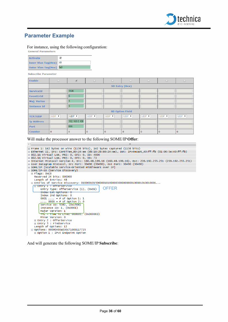
Parameter Example
For instance, using the following configuration:
Will make the processor answer to the following SOME/IP Offer:
And will generate the following SOME/IP Subscribe:
OFFER

Page 37 of 60
SUB-
Page 38 of 60
802.1AS
This chapter explains the current support of the MediaGateway for 802.1AS protocol, offered by Tech- nica as an extra cost functionality.
802.1AS is a protocol used between two or more devices to synchronize all of them through an Ethernet communication. This synchronization allow two or more devices (one master and one or multiple slaves) to transmit/receive time-critical information as audio or video through a physical link and assures that all the devices will handle the same time reference to encode/decode correctly the information.
This special software allows to maintain the synchronization between the 802.1AS connected devices, receiving, modifying and creating new corrected packets for the 802.1AS protocol, correcting so the possible delays generated for the routing through the Switch and the propagation delays of the cables.
Protocol
The software allows MediaGateway to be converted in a time-aware system bridge, which implements the transport of time-synchronization information and also the mechanism for the measurement of the propagation delay.
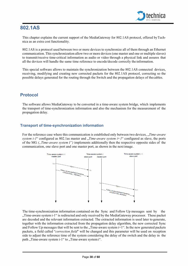
Transport of time-synchronization information
For the reference case where this communication is established only between two devices, „Time-aware system i-1“ configured as 802.1as master and „Time-aware system i+1“ configured as slave, the ports of the MG („Time-aware system I”) implements additionally then the respective opposite sides of the communication, one slave port and one master port, as shown in the next image.
The time-synchronization information contained on the Sync and Follow Up messages sent by the „Time-aware system i-1“ is redirected and only received by the MediaGateway processor. These packet are decoded and the relevant information extracted. The extracted information is used later to generate, together with the information extracted from the propagation delay algorithm, the new corrected Sync and Follow Up messages that will be sent to the „Time-aware system i+1“. In the new generated packets packets, a field called “correction field” will be changed and this parameter will be used on reception side to adjust the reference time of the system considering the delay of the switch and the delay in the path „Time-aware system i-1“ to „Time-aware system i“.

Page 39 of 60
Propagation delay measurement
For the correct adjust of the time reference transmitted by the Sync and Follow Up Packets, the delay between the initiator of the protocol „Time-aware system i-1“ and the first slave port of the MediaG- ateway „Time-aware system i“, should be measured
The measures of the propagation delay are performed by each attached link of a 802.1as communica- tions, it means each side of the link will generate and response to these packets, called Pdelay_Request, Pdelay_Response and Pdelay_Response_Follow_Up.

Page 40 of 60
Using 802.1 AS
MediaGateways allows the user to configure through the webpage six different bridges. Each of them offers two possibilities: BridgeX_Master or BridgeX_Slave. Each Broad-R Reach port can set as:
1. Disabled: Port will not take part of any 802.1AS traffic. 2. BridgeX_Slave: Only one per BridgeX. It will receive 801.2AS traffic from an external
master. 3. BridgeX_Master: Port will send 802.1AS traffic coming from it´s BridgeX_Slave.
Only one port in each bridge can receive the information of one attached 802.1AS Master. This means that only one port of this MediaGateway BridgeX should be configured as a BridgeX_Slave, but more than one port of the same BridgeX can be configured as BridgeX_Master, allowing so a distribution of the time reference 1 to N (with all the devices of the bridge sharing the same time reference, with N limited to 3).
4. Master_802.1AS: Port will work as 802.1AS Master Clock.
Traffic capture of a Master Clock

Page 41 of 60
Limitations
Due the need of working constantly with a high precision timestamping’s and the huge number of pack- ets pro 802.1AS OABR port that should be received and transmitted by the microcontroller of the Me- diaGateway there are some limitations that the user has to know before start to use it.
• The implementation allows only the use of the 802.1AS in the 12xOABR Ports of the MediaG-
ateway, due technical reasons the use of the protocol 802.1AS on the Ethernet Ports is not pos- sible.
• A Bridge should be formed by at least one port configured as Bridge_Slave (Connected with
802.1AS Master) and up to 3 Ports configured as Bridge_Master (Connected with 802.1AS Slave). It means the next possibilities pro Bridge are allowed: 1BS:1BM, 1BS:2BM and 1BS:3BM.
• For a correct synchronization, all ports that forms one Bridge (2 to 4 ports) should be connected
to the same Broadcom Ethernet Switch. o Broadcom Ethernet Switch 1: OABR Ports 0 to 3 o Broadcom Ethernet Switch 2: OABR Ports 4 to 7 o Broadcom Ethernet Switch 3: OABR Ports 8 to 11
• For the use of the 802.1AS Bridge functionality of the MG, the configuration of the MediaG- ateway should use unidirectional VLANs. The implementation won´t be functional using bidi- rectional VLANs.
• For 802.1AS should not be used together with traffic injection.
This means that no Ethernet Test Tools should generate traffic and routed using a MediaGate- way while 802.1AS is being used.

Page 42 of 60
VLAN Configuration This chapter describes the Virtual Local Area Network (VLAN) feature supported by internal switches present in the device. MediaGateway provides flexible VLAN configuration for each ingress (receiving) port.
Note: It is not possible to cover all of possible combinations that VLAN feature provides. It
will be explained as accurate as possible with a couple of uses cases.
VLAN Basics A Virtual LAN (VLAN) is a logical switched LAN formed by segmenting physical Local Area Net- works (LANs).
Separating a switched LAN into one or more VLANS provides multiple advantages:
1. Multicast and Broadcast packages flood are limited only to the required segments to save LAN
bandwidth. 2. Provides security. LAN traffic is restricted only to its specific segment.
3. Eases management by logically grouping ports across multiples switches.
VLAN work in the same was as physical LANs. Source device sends a packet to an end station or network device inside the same VLAN.
The MediaGateway allows the user to create Virtual Local Area Networks (VLANs), in order to sepa- rate traffic of different sources and providing a better general performance.
Port-Based VLAN MediaGateway uses port-based VLAN. This feature partitions the switching ports into a virtual private domains designated on a per-port basis. Data switching outside of the port private domain is not al- lowed.
The port-based VLAN feature works as a filter, rejecting all the traffic destined to non-private domain ports.
Once a packet is received, MediaGateway´s switch tries to identify the VLAN for the received packet. A port based VLAN determines the membership of a data frame by examining the configuration of the port that received the transmission or reading a portion of the data frame’s tag header. A four-byte field in the header is used to identify the VLAN. This VLAN identification indicates what VLAN the frame belongs to. If the frame has no tag header, the switch checks the VLAN setting of the port that received the frame. If the switch has been configured for port based VLAN support, it assigns the port’s VLAN identification to the new frame.
Page 43 of 60
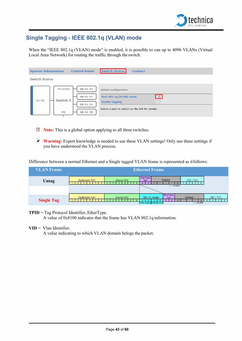
Single Tagging - IEEE 802.1q (VLAN) mode
When the “IEEE 802.1q (VLAN) mode” is enabled, it is possible to can up to 4096 VLANs (Virtual Local Area Network) for routing the traffic through the switch.
Note: This is a global option applying to all three switches. Warning: Expert knowledge is needed to use these VLAN settings! Only use these settings if
you have understood the VLAN process.
Difference between a normal Ethernet and a Single tagged VLAN frame is represented as it follows:
VLAN Frame Ethernet Frame
Untag
Single Tag
TPID = Tag Protocol Identifier, EtherType.
A value of 0x8100 indicates that the frame has VLAN 802.1q information.
VID = Vlan Identifier. A value indicating to which VLAN domain belogs the packet.

Page 44 of 60
View of the Port Configuration with Single Tagging activated:
Once IEEE 802.1q (VLAN) mode is enabled, several fields common to all ports will be avaliable: • Default VLAN ID: User can set the default VLAN identifier for this port.
Note: Untagged frames received to this port will be tagged with its Default VLAN ID.
If user does not set a Default VLAN ID, frames will be tagged with ID=1 at ingress. • VLAN Membership: Setting a “VLAN membership” ID makes the port a member in the given
virtual LAN. The switch will route (“forward”) packets which are tagged with one of these IDs to this port.
• VLAN to untag: Packets matching this list of VLAN IDs will be untagged at egress (“outgoing”). • Drop ingress packets with:
• inner VLAN IDs: Packets matching this list of VLAN IDs will be dropped. This fields may be filled with comma or space separated lists of numbers (VLAN IDs). The VLAN IDs are entered in 3 digit hexadecimal format. Valid numbers range from 001 to FFF.

Page 45 of 60
Single Tagging Example
If user needs to analyze traffic between a Camera and ICAM to a “stand alone” datalogger or a computer using a Traffic analyzer, following setup can meet this purpose. User wants to:
1. Set VLAN for accessing to MediaGateway´s webpage. 2. Set VLAN between ports BR-S1-P3 and BR-S1-P1 and redirect it to Log Device at S2-P5.
Setting VLAN for MediaGateway´s webpage. a. For PC-Config port (S1-P5) we set a both VLAN and a VLAN Membership to 0x49
Warning: As our computer is not using VLAN, we untag packets.
b. For CPU port, we set the same VLAN as in PC-Config.
Warning: Mediagateway´s CPU is not using VLANs. Make sure you untag the frames.
VLAN = 0x80
ICAM ECU
Page 46 of 60
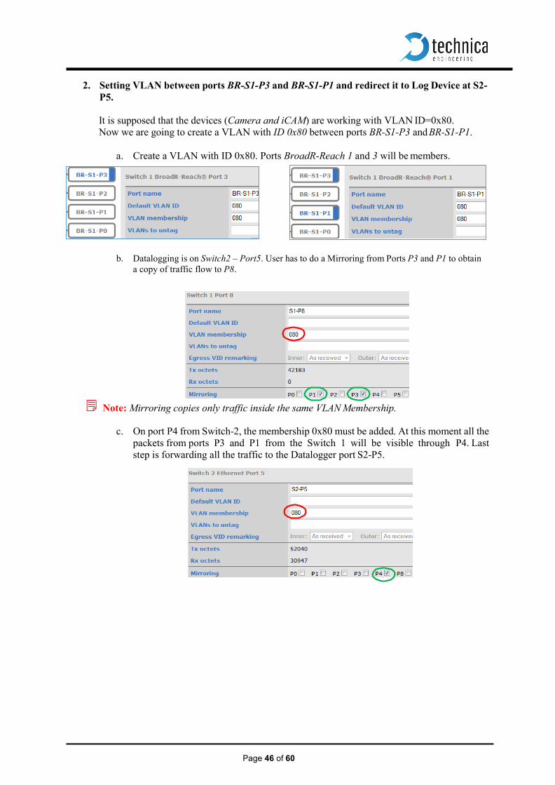
2. Setting VLAN between ports BR-S1-P3 and BR-S1-P1 and redirect it to Log Device at S2- P5.
It is supposed that the devices (Camera and iCAM) are working with VLAN ID=0x80. Now we are going to create a VLAN with ID 0x80 between ports BR-S1-P3 and BR-S1-P1.
a. Create a VLAN with ID 0x80. Ports BroadR-Reach 1 and 3 will be members.
b. Datalogging is on Switch2 – Port5. User has to do a Mirroring from Ports P3 and P1 to obtain
a copy of traffic flow to P8.
Note: Mirroring copies only traffic inside the same VLAN Membership.
c. On port P4 from Switch-2, the membership 0x80 must be added. At this moment all the packets from ports P3 and P1 from the Switch 1 will be visible through P4. Last step is forwarding all the traffic to the Datalogger port S2-P5.

Page 47 of 60
Double Tagging - IEEE 802.1q (VLAN) mode Media Gateway supports Double tagging. This feature can be enabled at the global configuration.
Note: This is a global option applying to all three switches.
This feature allows to use a second tag “Outer Tag” besides the Single tag “Inner Tag”. This extra tag (Double tag) provides an addition layer of tagging to the existing IEEE 802.1Q VLAN. When the double-tagging feature is enabled, users can expect two VLAN tags in a frame.
TPID = Tag Protocol Identifier, EtherType.
A value of 0x9100 indicates that the frame has double tag information.
Outer VID = Tag close to Source MAC is the ISP tag (Outer Tag).
Inner VID = Tag following is the Customer tag (Inner Tag).
Untag
Single Tag
Double Tag
VLAN Frame Ethernet Frame
Page 48 of 60
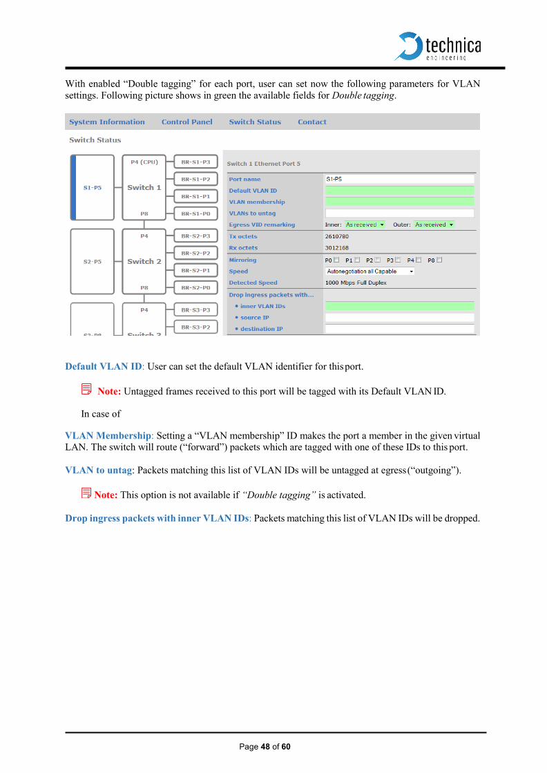
With enabled “Double tagging” for each port, user can set now the following parameters for VLAN settings. Following picture shows in green the available fields for Double tagging.
Default VLAN ID: User can set the default VLAN identifier for this port.
Note: Untagged frames received to this port will be tagged with its Default VLAN ID.
In case of
VLAN Membership: Setting a “VLAN membership” ID makes the port a member in the given virtual LAN. The switch will route (“forward”) packets which are tagged with one of these IDs to this port.
VLAN to untag: Packets matching this list of VLAN IDs will be untagged at egress (“outgoing”).
Note: This option is not available if “Double tagging” is activated.
Drop ingress packets with inner VLAN IDs: Packets matching this list of VLAN IDs will be dropped.

Page 49 of 60
If double tagging is active the “Normalization” process takes place on all ingress packets on all ports. The normalization process modifies all incoming packets with one or zero VLAN tags so that every packet has two VLAN tags afterwards. Every packet that flows through the switch is double tagged. Three different cases of normalization are possible:
1. Packet is received with two VLAN tags (double tagged) The packet will be left unchanged The packet will be forwarded if the packet VLAN is matching its Outer VLAN membership.
2. Packet is received with one VLAN tag (a single tagged packet with a so called customer tag /inner
tag) A second tag (a so called ISP /outer tag) with TPID 0x9100 will be added with configured with the
“Default VLAN” ID for this port to the packet during normalization.
3. A packet is received without any VLAN tags In this case, the normalization process adds two VLAN tags, the inner tag with TPID 0x8100 and
the outer tag with TPID 0x9100. Both tags will hold the “Default VLAN” ID of this port. With double tagging enabled, only the outer tag (the one with TPID 0x9100) is relevant for frame forwarding, i.e. the “VLAN membership” refers to the outer tag. TPID = Tag Protocol Identifier, EtherType A value of 0x8100 indicates that the frame has VLAN 802.1q information. A value of 0x9100 indicates that the frame has QinQ (Double Tagging).
With “Egress VID remarking” (available if double tagging is enabled only) you can specify, how to modify the packets before they are sent on this port. Three options are available for inner and outer VLAN tag:
1. “As received” means the tag shall left unchanged as the packet was received from its ingress port. If this tag was there before normalization it shall be sent with the same value. If no tag was there on ingress it shall be sent without this tag.
2. “Normalized” means that the tag shall be sent as the internally normalized VLAN tag.
3. “Remove” indicates that this tag shall be removed before the packet is transmitted.
Page 50 of 60
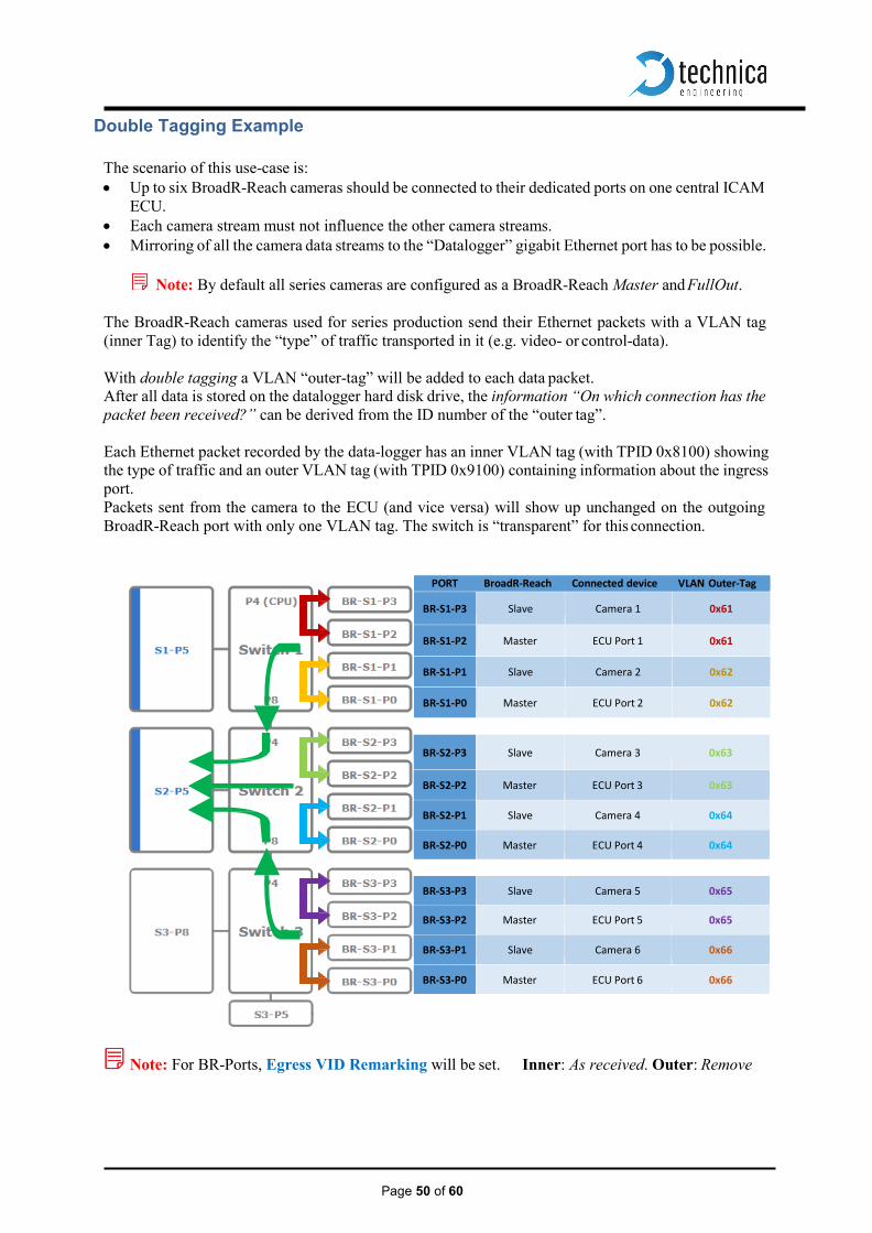
Double Tagging Example
The scenario of this use-case is: • Up to six BroadR-Reach cameras should be connected to their dedicated ports on one central ICAM
ECU. • Each camera stream must not influence the other camera streams. • Mirroring of all the camera data streams to the “Datalogger” gigabit Ethernet port has to be possible.
Note: By default all series cameras are configured as a BroadR-Reach Master and FullOut.
The BroadR-Reach cameras used for series production send their Ethernet packets with a VLAN tag (inner Tag) to identify the “type” of traffic transported in it (e.g. video- or control-data).
With double tagging a VLAN “outer-tag” will be added to each data packet. After all data is stored on the datalogger hard disk drive, the information “On which connection has the packet been received?” can be derived from the ID number of the “outer tag”.
Each Ethernet packet recorded by the data-logger has an inner VLAN tag (with TPID 0x8100) showing the type of traffic and an outer VLAN tag (with TPID 0x9100) containing information about the ingress port. Packets sent from the camera to the ECU (and vice versa) will show up unchanged on the outgoing BroadR-Reach port with only one VLAN tag. The switch is “transparent” for this connection.
PORT BroadR-Reach Connected device VLAN Outer-Tag
BR-S1-P3 Slave Camera 1 0x61
BR-S1-P2 Master ECU Port 1 0x61
BR-S1-P1 Slave Camera 2 0x62
BR-S1-P0 Master ECU Port 2 0x62
BR-S2-P3
Slave
Camera 3
0x63
BR-S2-P2 Master ECU Port 3 0x63
BR-S2-P1 Slave Camera 4 0x64
BR-S2-P0 Master ECU Port 4 0x64
BR-S3-P3 Slave Camera 5 0x65
BR-S3-P2 Master ECU Port 5 0x65
BR-S3-P1 Slave Camera 6 0x66
BR-S3-P0 Master ECU Port 6 0x66
Note: For BR-Ports, Egress VID Remarking will be set. Inner: As received. Outer: Remove

Page 50 of 60
The “Datalogger” gigabit Ethernet port and the internal ports (P4, P8) connecting the three switches are configured so that all incoming BroadR-Reach packets will be mirrored to the data-logging port, regard- less of the address resolution learning mechanism of the switches (“promiscuous mode”). To achieve this, suitable mirror maps are defined as well as the VLAN Memberships of the BR-Ports for the internal ports (S1-P8 and S3-P4) and the data-logging port (S2-P5).
The gigabit Ethernet port “Config-PC” shares a private VLAN (ID 0x049) with port S1-P4 to be able to reach the internal CPU of the MediaSwitch for configuration and status-monitoring. All outgoing pack- ets on the “Config-PC” port will be untagged (all VLAN tags removed) for usage with a standard desk- top PC.
Note: There is a pre-configured port-based forward map that avoids packet-forwarding from ports other than the “Config-PC” port to the CPU port (S1-P4). This rule is intended to prevent flooding the CPU with useless packets and prevent loops. This implies that the integrated webserver of the MediaSwitch is reachable via the port “Config-PC” only.
Page 51 of 60
MediaGateway Remote Control
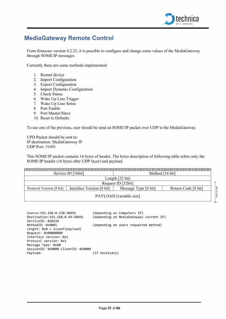
From firmware version 4.2.23, it is possible to configure and change some values of the MediaGateway through SOME/IP messages. Currently there are some methods implemented:
1. Restart device 2. Import Configuration 3. Export Configuration 4. Import Dynamic Configuration 5. Check Status 6. Wake Up Line Trigger 7. Wake Up Line Sense 8. Port Enable 9. Port Master/Slave 10. Reset to Defaults
To use one of the previous, user should be send an SOME/IP packet over UDP to the MediaGateway. UPD Packet should be sent to: IP destination: MediaGateway IP UDP Port: 31491 This SOME/IP packet contains 16 bytes of header. The bytes description of following table refers only the SOME/IP header (16 bytes after UDP layer) and payload.
0 1 2 3 4 5 6 7 8 9 10 11 12 13 14 15 16 17 18 19 20 21 22 23 24 25 26 27 28 29 30 31
Service ID [16bit] Method [16 bit] Length [32 bit]
Request ID [32bit] Protocol Version [8 bit] Interface Version [8 bit] Message Type [8 bit] Return Code [8 bit]
PAYLOAD [variable size]
Source:192.168.0.150:30491 (depending on Computers IP) Destination:192.168.0.49:30491 (depending on MediaGateways current IP) ServiceID: 0x0124 MethodID: 0x0001 (depending on users requested method) Length: 0x8 + sizeof(payload) Request: 0x00000000 Interface version: 0x1 Protocol version: 0x1 Message Type: 0x80 SessionID: 0x0000 ClientID: 0x0000 Payload: (if necessary)

Page 52 of 60
The fields of a SOME/IP request (message from user to MediaGateway) differs only on: Method ID Length (depending on used payload) Payload
Reset device This method performs a complete device reset. Configuration after a device restart will loaded from flash. Method ID: 0x0001
a) REQUEST: Method ID has to be set to 0x0001. No payload needed.
b) RESPONSE: This method returns a SOME/IP Message with Return Code 0x00 (OK) before restarting.
Import configuration Same behavior as Import button from Webpage. It will store the load configuration into the flash New settings will be applied at next device restart. Method ID: 0x0002
a) REQUEST: Payload of this message is the configuration file as HEX stream.
Note: Length field should be adjusted
b) RESPONSE: This method returns a SOME/IP Message with Return Code 0x00 (OK)

Page 53 of 60
Export Config Same behavior as Export button from Webpage. Response message from MediaGateway will contain the CFG file in its payload as HEX stream. Method ID: 0x0003
a) REQUEST: Method ID has to be set to 0x0003. No payload needed.
b) RESPONSE: This method returns a SOME/IP Message with Return Code 0x00 (OK)
Note: Payload of this message is the configuration file as HEX stream.
Dynamic Config It is useful for automation of tests which different configurations are needed. This method loads a configuration and applies it with “fast restart”. No complete reset is needed. When Dynamic Configuration is applied and running, Host LED will blink faster as in normal operation. This Dynamic Configuration will run until next device restart or new load dynamic configuration.
Note: At a device restart, current configuration stored in flash will be applied. Method ID: 0x0004
a) REQUEST: Same as Import Configuration Method. Method ID has to be set to 0x0004 b) RESPONSE: Same as Import Configuration Method.

Page 54 of 60
Check Status This method will response with the current status of the device. Current status can be: Normal Mode: When current configuration is loaded from flash. Dynamic Mode: When current configuration is loaded dynamically. In dynamic mode, Host LED will blink a little faster. Method ID: 0x0005
a) RESPONSE: This method returns a SOME/IP Message with Return Code 0x00 (OK). The response payload will contain: Normal Operation or Dynamic Operation
Payload Byte 0 0x01 0x02 Normal Dynamic
Set WakeUp Line Status This method provide users the possibility of driving the wakeup line to high or low level. Two wake up lines are available in the MediaGateway Method ID: 0x0006
a) REQUEST: Method ID has to be set to 0x0006. Payload will have to contain the pair values {wakeup line, line status}
If user want to set WakeUp Lines to High, the payload should contain this two bytes:
Payload Byte 0 (line select) Byte 1(line new status) 0x01 0x02 0x00 0x01 WakeUp Line 1 or 2 Low or High
b) RESPONSE: This method returns a SOME/IP Message with Return Code 0x00 (OK) if values
passed are correct. Otherwise it will return Code 0x01 (NOT_OK)
Get WakeUp Line Status This method returns the state of the selected wake up line. Method ID: 0x0007
a) REQUEST: Method ID has to be set to 0x0007. No payload needed.
b) RESPONSE: This method returns a SOME/IP Message with Return Code 0x00 (OK) and its payload will contain the current status of both WakeUp Lines
Payload Byte 0 (Status Line 1) Byte 1 (Status Line 2) 0x00 0x01 0x00 0x01 Low or High Low or High
Page 55 of 60
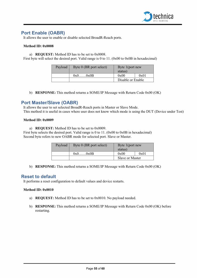
Port Enable (OABR) It allows the user to enable or disable selected BroadR-Reach ports. Method ID: 0x0008
a) REQUEST: Method ID has to be set to 0x0008. First byte will select the desired port. Valid range is 0 to 11. (0x00 to 0x0B in hexadecimal)
Payload Byte 0 (BR port select) Byte 1(port new status)
0x0……0x0B 0x00 0x01 Disable or Enable
b) RESPONSE: This method returns a SOME/IP Message with Return Code 0x00 (OK)
Port Master/Slave (OABR) It allows the user to set selected BroadR-Reach ports in Master or Slave Mode. This method it is useful in cases where user does not know which mode is using the DUT (Device under Test) Method ID: 0x0009
a) REQUEST: Method ID has to be set to 0x0009. First byte selects the desired port. Valid range is 0 to 11. (0x00 to 0x0B in hexadecimal) Second byte refers to new OABR mode for selected port. Slave or Master.
Payload Byte 0 (BR port select) Byte 1(port new status)
0x0……0x0B 0x00 0x01 Slave or Master
b) RESPONSE: This method returns a SOME/IP Message with Return Code 0x00 (OK)
Reset to default It performs a reset configuration to default values and device restarts. Method ID: 0x0010
a) REQUEST: Method ID has to be set to 0x0010. No payload needed.
b) RESPONSE: This method returns a SOME/IP Message with Return Code 0x00 (OK) before restarting.

Page 56 of 60
Hardware Variants Different versions of the MediaGateway have been built. Here some information about hardware vari- ants. The HW version is stated on the label on the bottom of the case.
BroadR-Reach Analog Filter: All filter versions are compatible with each other.
Hardware Version 2.0 and above have the following filter for all BroadR-Reach ports:
L32 and L35 are placement options. In Version 2.0 and 2.1 the CMC L32 is not fixed. In Version 2.2 and above the CMC L35 is not fixed.
Debug connector There is a debug connector on the Tyco Connector side of the case. This small connector is only for customer service purpose.
Warning: Do not connect anything to this port.

Page 57 of 60
Startup Time The startup time on the device has been greatly reduced in firmware version 3.7. It is dependent of the used hardware version.
MediaSwitch (all Versions), MediaGateway Version up to 2.1:
PowerUp and Processor Boot time: 65 ms Configuration time depending on complexity: 173 ms BroadR-Reach LinkUp time: 20-130 ms
MediaGateway Version since 2.1a:
PowerUp and Processor Boot time: 65 ms Configuration time depending on complexity: 47-55 ms BroadR-Reach LinkUp time: 20-130 ms
Note: On the RJ45 gigabit ports the Linkup time is about 3 to 4 seconds. This is because of IEEE Auto Negotiation which has to be done in gigabit mode.

Page 58 of 60
Bootloader Update The bootloader of the device may be updated by the following process:
Warning: Never downgrade the bootloader or application to a former version. This could cause serious problems.
Note: If you update the application the bootloader should also be updated to the latest version.
Note: For a bootloader update it is necessary to delete the firmware of the device. You will have
to update the application firmware after bootloader update
Warning: Not following this instruction may cause erroneous states of the device. You will have to send it back to Technica Engineering for repair. Technica Engineering may charge sup- port fees for this service.
Warning: Only upgrade to the latest firmware. Do not downgrade to old releases. Otherwise it may happen that you cannot access the device anymore because old firmware does not support new hardware.
Note: You need to have administration privileges on a Windows PC to be able to do the boot- loader and firmware update on the MediaGateway.
1. Power up the device by a stable 12 Volt DC power supply. Do not switch off the power supply
during the update process.
2. It is recommended to connect the Wake-up line (Pin 8 of the black MQS connector) to 12 Volt of the same power supply to make sure the ECU is awake during update.
3. Connect a Windows PC with a RJ45 cable directly to the left RJ45 Port of the MediaGateway
and make sure there is a link. Do not connect a switch in between.
4. Disconnect all other Ethernet, CAN, FlexRay, LIN and BroadR-Reach links from the MediaG- ateway.
5. Disable the Firewall of the Windows PC. Set the network device of the PC to the same subnet
as the MediaGateway. (For example 192.168.0.100 and 255.255.255.0)
6. Check that your firmware package you received from Technica Engineering contains the fol- lowing files:
redtool.exe redboot.srec EthernetSwitch.crc.srec redboot-updater.srec
You will need to have java installed on your PC.
7. Check that the “Host” LED toggles slowly.
8. Check that you can access the website at 192.168.0.49 (or whatever the IP address of the Medi-
aGateway is).
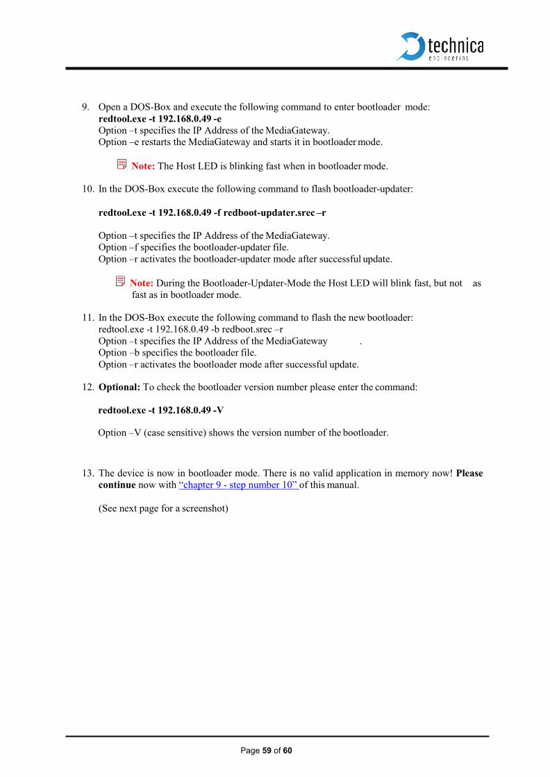
Page 59 of 60
9. Open a DOS-Box and execute the following command to enter bootloader mode: redtool.exe -t 192.168.0.49 -e Option –t specifies the IP Address of the MediaGateway. Option –e restarts the MediaGateway and starts it in bootloader mode.
Note: The Host LED is blinking fast when in bootloader mode.
10. In the DOS-Box execute the following command to flash bootloader-updater:
redtool.exe -t 192.168.0.49 -f redboot-updater.srec –r
Option –t specifies the IP Address of the MediaGateway. Option –f specifies the bootloader-updater file. Option –r activates the bootloader-updater mode after successful update.
Note: During the Bootloader-Updater-Mode the Host LED will blink fast, but not as
fast as in bootloader mode.
11. In the DOS-Box execute the following command to flash the new bootloader: redtool.exe -t 192.168.0.49 -b redboot.srec –r Option –t specifies the IP Address of the MediaGateway . Option –b specifies the bootloader file. Option –r activates the bootloader mode after successful update.
12. Optional: To check the bootloader version number please enter the command:
redtool.exe -t 192.168.0.49 -V
Option –V (case sensitive) shows the version number of the bootloader.
13. The device is now in bootloader mode. There is no valid application in memory now! Please continue now with “chapter 9 - step number 10” of this manual.
(See next page for a screenshot)

Page 55 of 60
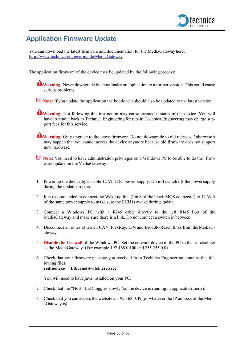
Page 56 of 60
Application Firmware Update
You can download the latest firmware and documentation for the MediaGateway here: http://www.technica-engineering.de/MediaGateway
The application firmware of the device may be updated by the following process:
Warning: Never downgrade the bootloader or application to a former version. This could cause serious problems.
Note: If you update the application the bootloader should also be updated to the latest version.
Warning: Not following this instruction may cause erroneous states of the device. You will have to send it back to Technica Engineering for repair. Technica Engineering may charge sup- port fees for this service.
Warning: Only upgrade to the latest firmware. Do not downgrade to old releases. Otherwise it may happen that you cannot access the device anymore because old firmware does not support new hardware.
Note: You need to have administration privileges on a Windows PC to be able to do the firm-
ware update on the MediaGateway.
1. Power up the device by a stable 12 Volt DC power supply. Do not switch off the power supply during the update process.
2. It is recommended to connect the Wake-up line (Pin 8 of the black MQS connector) to 12 Volt
of the same power supply to make sure the ECU is awake during update.
3. Connect a Windows PC with a RJ45 cable directly to the left RJ45 Port of the MediaGateway and make sure there is a link. Do not connect a switch in between.
4. Disconnect all other Ethernet, CAN, FlexRay, LIN and BroadR-Reach links from the MediaG-
ateway.
5. Disable the Firewall of the Windows PC. Set the network device of the PC to the same subnet as the MediaGateway. (For example 192.168.0.100 and 255.255.0.0)
6. Check that your firmware package you received from Technica Engineering contains the fol-
lowing files: redtool.exe EthernetSwitch.crc.srec
You will need to have java installed on your PC.
7. Check that the “Host” LED toggles slowly (so the device is running in application mode).
8. Check that you can access the website at 192.168.0.49 (or whatever the IP address of the Medi-
aGateway is).

Page 57 of 60
9. Open a DOS-Box and execute the following command to enter bootloader mode:
redtool.exe -t 192.168.0.49 -e
Option –t specifies the IP Address of the MediaGateway. Option –e restarts the MediaGateway and starts it in bootloader mode.
Note: The Host LED is blinking fast when in bootloader mode.
10. In the DOS-Box execute the following command:
redtool.exe -t 192.168.0.49 -f EthernetSwitch.crc.srec -r
Option –t specifies the IP Address of the MediaGateway. Option –f specifies the new firmware file. Option –r activates the application mode after successful update.
Note: during the update process the Host LED will stop to blink. This is a normal condition. Do
not reset the device! The update process will last about one minute. When the update is finished the Host LED will toggle slowly again.
11. You can re-activate your Windows firewall after successful update.
Page 58 of 60
Frequently Asked Questions – FAQ
Q: What is the delay time for Ethernet packets through the switch? A: The propagation delay of the switch depends on the load. The switch works collision free.
So buffers are used to solve collisions. These buffers delay packets for some time and cause delay jitter. On high load these times rise exponential. On normal load the delay should be about 0.3 ms. But if the packed passes all 3 switches it may sum up to about 1 ms.
Q: Is AVB supported? A: Currently Audio Video Bridging is not supported.
It is planned to implement automotive time synchronization .1AS features as soon as they have been fully specified.
Q: What to do to get CAN, FlexRay and LIN supported? A: In the standard firmware edition these interfaces are not supported. Please contact the
sales of Technica Engineering GmbH to get information about advanced software fea- tures.
Q: When I use the MediaGateway in my test setup, I cannot access the configuration
website anymore. A: The host microcontroller is jammed by mislead packets. Please use a valid VLAN
configuration and avoid too much broadcast packets.
Q: After a firmware update the host LED is still blinking fast. What to do? A: The firmware update failed and the host is still in bootloader mode. Please restart the
device and try to update the application again as described in this manual.
Q: All LEDs on the front of the MediaGateway are lit permanently? A: The host microcontroller is not running. Maybe a firmware update has failed. Please
send the device to Technica Engineering GmbH for service.
Q: I have problems with the website user interface. A: The website is tested with Firefox and Internet Explorer. Firefox is preferred. Chome is
not supported.
Q: I have problems with firmware update. TFTP Timeout error is appearing. A: It is known that some Ethernet-USB adapters are having problems with Update procedure.
Try to connect your MediaGateway directly ton your integrated LAN Adapter.
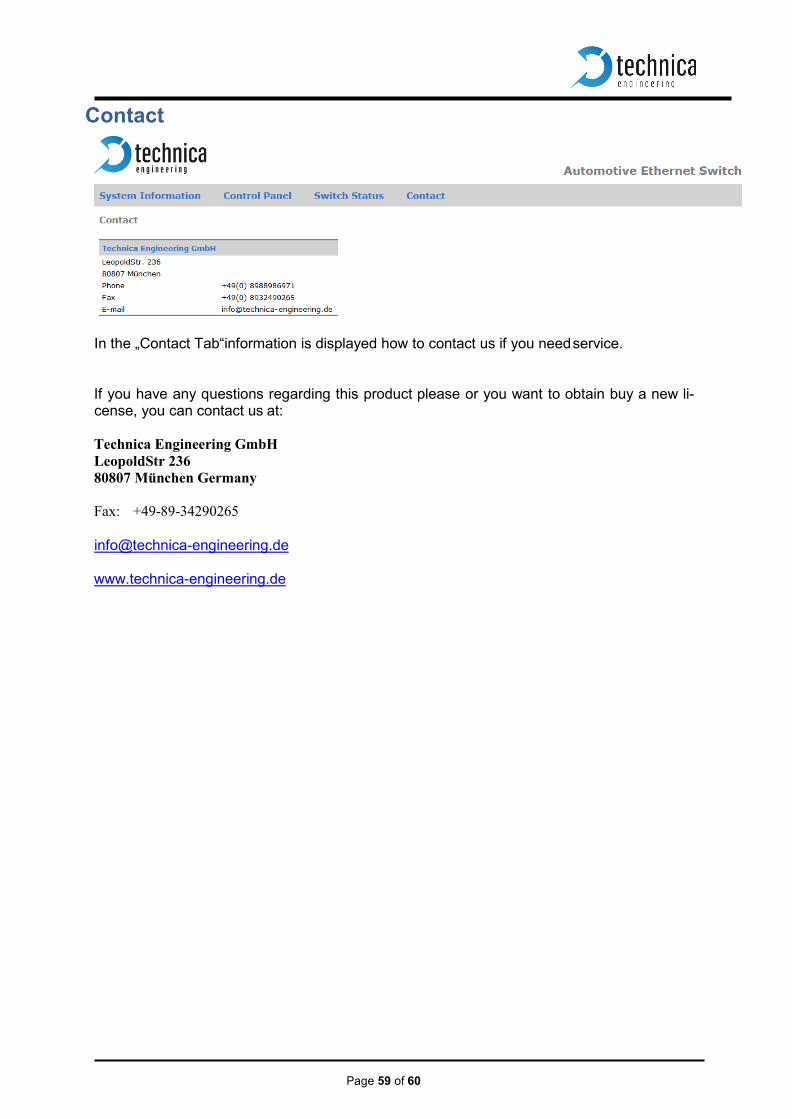
Page 59 of 60
Contact
In the „Contact Tab“information is displayed how to contact us if you need service.
If you have any questions regarding this product please or you want to obtain buy a new li- cense, you can contact us at:
Technica Engineering GmbH LeopoldStr 236 80807 München Germany Fax: +49-89-34290265
www.technica-engineering.de