bronze & iron gate, globe & check valve index bronze ... · 118-‐fp 15 ib912 mss...
TRANSCRIPT

The information presented on this sheet is correct at time of publication. Hammond Valve reserves the right to change design and/or materials without notice. For our Installation, Operation and Maintenance Manual and the most current product information go to www.hammondvalve.com. Hammond Valve is a registered trademark of Milwaukee Valve.
State of California Prop 65 WARNING: Cancer and Reproductive Harm. For more information visit www.p65warnings.ca.gov.
Bronze & Iron Gate, Globe & Check Valve Index
Rev 11/19
Bronze & Iron Gate,Globe & Check Valve Index
Model Spec Page Model Spec Page118-‐FP 15 IB912 MSS SP-‐80 39IB412 MSS SP-‐80 30 IB944 MSS SP-‐80 46IB413T MSS SP-‐80 25 IB945 MSS SP-‐80 44IB413TP2 MSS SP-‐80 26 IB946 MSS SP-‐80 43IB415 MSS SP-‐80 29 IB949 MSS SP-‐80 47IB418 MSS SP-‐80 24 943 40IB423 MSS SP-‐80 27 943P2 41IB434 MSS SP-‐80 28 947 42IB440 MSS SP-‐80 22 969 34IB440P2` MSS SP-‐80 23 IR1124 MSS SP-‐71 61IB444 MSS SP-‐80 31 IR1124-‐HI 2" -‐ 12" MSS SP-‐71 62IB454T MSS SP-‐80 33 IR1124-‐HI 14" -‐ 24" MSS SP-‐71 63IB463 MSS SP-‐80 32 IR1124-‐LW MSS SP-‐71 67IB610 16 IR1124-‐UL 66IB617 MSS SP-‐80 5 IR1126-‐HI 2" -‐ 12" MSS SP-‐71 64IB617P2 MSS SP-‐80 6 IR1126-‐HI 14" -‐ 24" MSS SP-‐71 65IB629 MSS SP-‐80 13 IR1138 MSS SP-‐70 48IB635 MSS SP-‐80 8 IR1138-‐HI MSS SP-‐70 49IB638 MSS SP-‐80 10 IR1140 MSS SP-‐70 51IB638P2 MSS SP-‐80 11 IR1140-‐HI 2" -‐ 12" MSS SP-‐70 52IB640 MSS SP-‐80 3 IR1140-‐HI 14" -‐ 24" MSS SP-‐70 53IB640P2 MSS SP-‐80 4 IR1140-‐UL 55IB641 MSS SP-‐80 12 IR1144-‐HI MSS SP-‐70 50IB646 MSS SP-‐80 9 IR1146-‐HI MSS SP-‐70 54IB645 MSS SP-‐80 1 IR116 MSS SP-‐85 58IB645P2 MSS SP-‐80 2 IR116-‐HI MSS SP-‐85 59IB647 MSS SP-‐80 7 IR1913-‐HI MSS-‐SP-‐70 69IB648 MSS SP-‐80 14 IR1937-‐HI MSS-‐SP-‐71 70IB650 MSS SP-‐80 17 IR313 MSS SP-‐85 60IB651 MSS SP-‐80 18 IR322-HI MSS-‐SP-‐71 68IB652 MSS SP-‐80 19 IR330 MSS-‐SP-‐70 56IB654 MSS SP-‐80 20 IR330-‐HI MSS-‐SP-‐70 57IB656 MSS SP-‐80 21 IR337-‐HI 71509Y MSS SP-‐80 37 IR9253 MSS-‐SP-‐125 72509YP2 MSS SP-‐80 38 IR9354 MSS-‐SP-‐125 73515Y MSS SP-‐80 45IB904/IB940 MSS SP-‐80 35IB904/IB940P2 MSS SP-‐80 36


The information presented on this sheet is correct at time of publication. Hammond Valve reserves the right to change design and/or materials without notice. For our Installation, Operation and Maintenance Manual and the most current product information go to www.hammondvalve.com. Hammond Valve is a registered trademark of Milwaukee Valve.
State of California Prop 65 WARNING: Cancer and Reproductive Harm. For more information visit www.p65warnings.ca.gov.
BI-1
Bronze Gate Valve125 SWP-200 WOG †
Non-Rising Stem 1/4” - 3” • Rising Stem 4”Solid Wedge Disc
Threaded Bonnet • Threaded EndsConforms to: MSS SP-80*
IB645 1/4”-4”
Rev 10
Note: Not intended for use in potable water.
DIMENSIONS - INCHES/MILLIMETERS
Units Size A B C CvInches
mm1/4 1.75
453.6392
2.0051 5.6
Inchesmm
3/8 1.8146
3.6392
2.0051 10.7
Inchesmm
1/2 2.0051
3.6392
2.0051
17.6
Inchesmm
3/4 2.1354
4.38111
2.5064
32.0
Inchesmm
1 2.5665
5.00127
2.7570
54.0
Inchesmm
1 1/4 2.7871
5.31135
3.1379
97.0
Inchesmm
1 1/2 2.8172
6.34161
3.5089
135.0
Inchesmm
2 3.3184
7.44189
3.7595
230.0
Inchesmm
2 1/2 4.19106
9.13232
4.75121
337.0
Inchesmm
3 4.63118
10.47266
5.25133
536.0
Inchesmm
4 5.50140
15.50394
5.25133
960.0
† Non-Shock* 4” is not covered in MSS SP-80
MATERIAL LISTNo. PART MATERIAL SPECIFICATION
1 Body Bronze ASTM B62
2 Bonnet Bronze ASTM B62
3 Wedge Bronze ASTM B62
4 Stem Bronze ASTM B62
5 Packing Nut Brass ASTM B283 C37700
6 Stuffing Box Brass ASTM B283 C37700
7 1 Gland Brass ASTM B283 C37700
8 Handwheel Nut Brass Commercial
9 Handwheel Mall. Iron Commercial
10 Packing Graphite Commercial
11 Name Plate Sh. Alum Commercial
1 Not used on 1/2” and smaller

The information presented on this sheet is correct at time of publication. Hammond Valve reserves the right to change design and/or materials without notice. For our Installation, Operation and Maintenance Manual and the most current product information go to www.hammondvalve.com. Hammond Valve is a registered trademark of Milwaukee Valve.
State of California Prop 65 WARNING: Cancer and Reproductive Harm. For more information visit www.p65warnings.ca.gov.
BI-2
Bronze Gate Valve200 psig @ 250°F †
Solid Wedge Disc • Non-Rising StemThreaded Bonnet • Press Ends
Conforms to: MSS SP-80
IB645 P2 1/2”-2”
DIMENSIONS - INCHES/MILLIMETERS
Units SizeSTD
Insertion Depth
A B C Cv
Inchesmm
1/2 0.8722
5.00127
3.6392
2.0051
17.6
Inchesmm
3/4 0.98166
5.71145
4.38111
2.5064
32.0
Inchesmm
1 0.98166
6.56167
5.00127
2.7570
54.0
Inchesmm
1 1/4 1.0226
6.85174
5.31135
3.1379
97.0
Inchesmm
1 1/2 1.4236
7.29185
6.34161
3.5089
135.0
Inchesmm
2 1.5840
9.31237
7.44189
3.7595
230.0
† Non-Shock
C
M
Y
CM
MY
CY
CMY
K
Drawing.pdf 1 3/30/16 8:22 PM
Press End Adapter (4151 Series)
12
With Press Ends
MATERIAL LISTNo. PART MATERIAL SPECIFICATION
1 Body Bronze ASTM B62
2 Bonnet Bronze ASTM B62
3 Wedge Bronze ASTM B62
4 Stem Bronze ASTM B62
5 Packing Nut Brass ASTM B283 C37700
6 Stuffing Box Brass ASTM B283 C37700
7 1 Gland Brass ASTM B283 C37700
8 Handwheel Nut Brass Commercial
9 Handwheel Mall. Iron Commercial
10 Packing Graphite Commercial
11 Name Plate Sh. Alum Commercial
12 Press AdaptersBrass Fitting W/EPDM O-Ring
ASTM C27450
1 Not used on 1/2” and smaller
Rev 2
Note: Not intended for use in potable water.
The information presented on this sheet is correct at time of publication. Hammond Valve reserves the right to change design and/or materials without notice. For our Installation, Operation and Maintenance Manual and the most current product information go to www.hammondvalve.com. Hammond Valve is a registered trademark of Milwaukee Valve.
State of California Prop 65 WARNING: Cancer and Reproductive Harm. For more information visit www.p65warnings.ca.gov.
BI-3
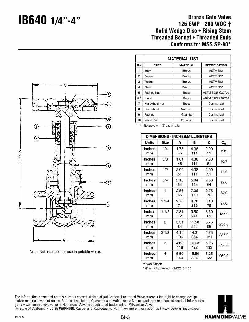
Bronze Gate Valve125 SWP - 200 WOG †
Solid Wedge Disc • Rising StemThreaded Bonnet • Threaded Ends
Conforms to: MSS SP-80*
IB640 1/4”-4”
Note: Not intended for use in potable water.
DIMENSIONS - INCHES/MILLIMETERS
Units Size A B C CvInches
mm1/4 1.75
454.38111
2.0051
5.6
Inchesmm
3/8 1.8146
4.38111
2.0051
10.7
Inchesmm
1/2 2.0051
4.38111
2.0051
17.6
Inchesmm
3/4 2.1354
5.84148
2.5064
32.0
Inchesmm
1 2.5665
7.06179
2.7570
54.0
Inchesmm
1 1/4 2.7871
8.78223
3.1379
97.0
Inchesmm
1 1/2 2.8172
9.50241
3.5089
135.0
Inchesmm
2 3.3184
11.50292
3.7595
230.0
Inchesmm
2 1/2 4.19106
14.31364
4.75121
337.0
Inchesmm
3 4.63118
16.63422
5.25133
536.0
Inchesmm
4 5.50140
15.50394
5.25133
960.0
† Non-Shock* 4” is not covered in MSS SP-80
MATERIAL LISTNo. PART MATERIAL SPECIFICATION
1 Body Bronze ASTM B62
2 Bonnet Bronze ASTM B62
3 Wedge Bronze ASTM B62
4 Stem Bronze ASTM B62
5 Packing Nut Brass ASTM B283 C37700
6 1 Gland Brass ASTM B124 C37700
7 Handwheel Nut Brass Commercial
8 Handwheel Mall. Iron Commercial
9 Packing Graphite Commercial
10 Name Plate Sh. Alum Commercial
1 Not used on 1/2” and smaller
Rev 8

The information presented on this sheet is correct at time of publication. Hammond Valve reserves the right to change design and/or materials without notice. For our Installation, Operation and Maintenance Manual and the most current product information go to www.hammondvalve.com. Hammond Valve is a registered trademark of Milwaukee Valve.
State of California Prop 65 WARNING: Cancer and Reproductive Harm. For more information visit www.p65warnings.ca.gov.
BI-4
IB640 P2 1/2”-2” Bronze Gate Valve200 psig @ 250°F †
Solid Wedge Disc • Rising StemThreaded Bonnet • Press Ends
Conforms to: MSS SP-80
C
M
Y
CM
MY
CY
CMY
K
Drawing.pdf 1 3/30/16 8:22 PM
Press End Adapter (4151 Series)
11
With Press Ends
DIMENSIONS - INCHES/MILLIMETERS
Units SizeSTD
Insertion Depth
A B C Cv
Inchesmm
1/2 0.8722
5.00127
4.38111
2.0051
17.6
Inchesmm
3/4 0.98166
5.71145
5.84148
2.5064
32.0
Inchesmm
1 0.98166
6.56167
7.06179
2.7570
54.0
Inchesmm
1 1/4 1.0226
6.85174
8.78223
3.1379
97.0
Inchesmm
1 1/2 1.4236
7.29185
9.50241
3.5089
135.0
Inchesmm
2 1.5840
9.31236
11.50292
3.7595
230.0
† Non-Shock
Note: Not intended for use in potable water.
MATERIAL LISTNo. PART MATERIAL SPECIFICATION
1 Body Bronze ASTM B62
2 Bonnet Bronze ASTM B62
3 Wedge Bronze ASTM B62
4 Stem Bronze ASTM B62
5 Packing Nut Brass ASTM B283 C37700
6 1 Gland Brass ASTM B124 C37700
7 Handwheel Nut Brass Commercial
8 Handwheel Mall. Iron Commercial
9 Packing Graphite Commercial
10 Name Plate Sh. Alum Commercial
11 Press AdapterBrass Fitting W/EPDM O-Ring
ASTM C27450
1 Not used on 1/2” and smaller
Rev 2

The information presented on this sheet is correct at time of publication. Hammond Valve reserves the right to change design and/or materials without notice. For our Installation, Operation and Maintenance Manual and the most current product information go to www.hammondvalve.com. Hammond Valve is a registered trademark of Milwaukee Valve.
State of California Prop 65 WARNING: Cancer and Reproductive Harm. For more information visit www.p65warnings.ca.gov.
BI-5
Bronze Gate Valve125 SWP - 200 WOG †
Solid Wedge Disc • Rising StemUnion Bonnet • Threaded Ends
Conforms to: MSS SP-80
IB617 1/4”-3”
Note: Not intended for use in potable water.
DIMENSIONS - INCHES/MILLIMETERS
Units Size A B C CvInches
mm1/4 1.75
455.13130
2.0051
5.6
Inchesmm
3/8 1.8848
5.13130
2.0051
10.7
Inchesmm
1/2 2.1354
5.50140
2.5064
17.6
Inchesmm
3/4 2.2557
6.25159
2.7570
32.0
Inchesmm
1 2.5665
7.19183
2.7570
54.0
Inchesmm
1 1/4 2.7871
8.56218
3.4487
97.0
Inchesmm
1 1/2 3.2583
9.63245
3.7595
135.0
Inchesmm
2 3.6392
11.75299
4.25108
230.0
Inchesmm
2 1/2 4.50114
14.50368
4.75121
337.0
Inchesmm
3 4.88124
16.75426
5.25133
536.0
† Non-Shock
MATERIAL LISTNo. PART MATERIAL SPECIFICATION
1 Body Bronze ASTM B62
2 Bonnet Bronze ASTM B62
3 Wedge Disc Bronze ASTM B62
4 Stem Bronze ASTM B62
5 Union Bonnet Nut Bronze ASTM B62
6 Packing Graphite Commercial
7 Gland Brass ASTM B124 C37700
8 Packing Nut Brass ASTM B283 C37700
9 Handwheel Mall. Iron Commercial
10 Name Plate Aluminum Commercial
11 Handwheel Nut Brass ASTM B 16
Rev 9
11
10
The information presented on this sheet is correct at time of publication. Hammond Valve reserves the right to change design and/or materials without notice. For our Installation, Operation and Maintenance Manual and the most current product information go to www.hammondvalve.com. Hammond Valve is a registered trademark of Milwaukee Valve.
State of California Prop 65 WARNING: Cancer and Reproductive Harm. For more information visit www.p65warnings.ca.gov.
BI-6
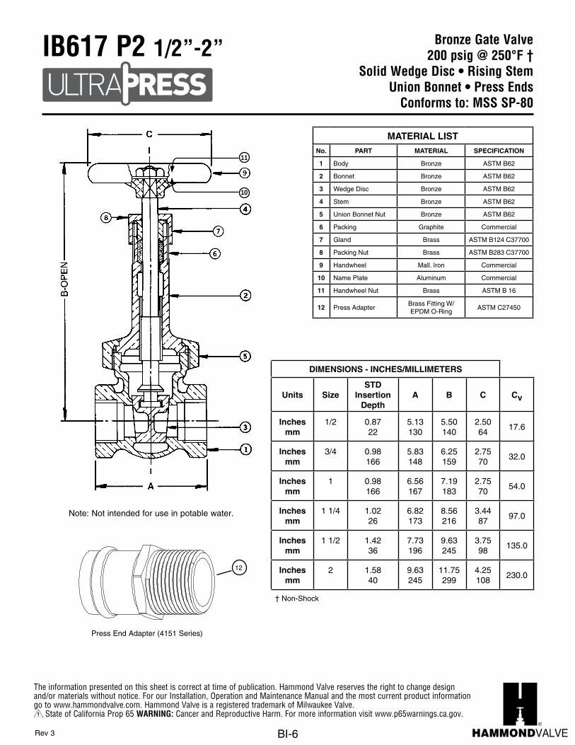
Bronze Gate Valve200 psig @ 250°F †
Solid Wedge Disc • Rising StemUnion Bonnet • Press Ends
Conforms to: MSS SP-80
IB617 P2 1/2”-2”
C
M
Y
CM
MY
CY
CMY
K
Drawing.pdf 1 3/30/16 8:22 PM
Press End Adapter (4151 Series)
12
DIMENSIONS - INCHES/MILLIMETERS
Units SizeSTD
Insertion Depth
A B C Cv
Inchesmm
1/2 0.8722
5.13130
5.50140
2.5064
17.6
Inchesmm
3/4 0.98166
5.83148
6.25159
2.7570
32.0
Inchesmm
1 0.98166
6.56167
7.19183
2.7570
54.0
Inchesmm
1 1/4 1.0226
6.82173
8.56216
3.4487
97.0
Inchesmm
1 1/2 1.4236
7.73196
9.63245
3.7598
135.0
Inchesmm
2 1.5840
9.63245
11.75299
4.25108
230.0
† Non-Shock
MATERIAL LISTNo. PART MATERIAL SPECIFICATION
1 Body Bronze ASTM B62
2 Bonnet Bronze ASTM B62
3 Wedge Disc Bronze ASTM B62
4 Stem Bronze ASTM B62
5 Union Bonnet Nut Bronze ASTM B62
6 Packing Graphite Commercial
7 Gland Brass ASTM B124 C37700
8 Packing Nut Brass ASTM B283 C37700
9 Handwheel Mall. Iron Commercial
10 Name Plate Aluminum Commercial
11 Handwheel Nut Brass ASTM B 16
12 Press AdapterBrass Fitting W/EPDM O-Ring
ASTM C27450
Rev 3
Note: Not intended for use in potable water.
11
10

The information presented on this sheet is correct at time of publication. Hammond Valve reserves the right to change design and/or materials without notice. For our Installation, Operation and Maintenance Manual and the most current product information go to www.hammondvalve.com. Hammond Valve is a registered trademark of Milwaukee Valve.
State of California Prop 65 WARNING: Cancer and Reproductive Harm. For more information visit www.p65warnings.ca.gov.
BI-7
Bronze Gate Valve125 SWP - 200 WOG †
Non-Rising Stem 3/8” - 3” • Rising Stem 4”Solid Wedge Disc
Threaded Bonnet • Solder EndsConforms to: MSS SP-80*
IB647 3/8”-4”
Note: Not intended for use in potable water.
DIMENSIONS - INCHES/MILLIMETERS
Units Size A B C D E CvInches
mm3/8 1.63
413.5691
2.0051
0.8822
0.3810
10.7
Inchesmm
1/2 1.8848
3.5691
2.0051
0.8822
0.5013
17.6
Inchesmm
3/4 2.5064
4.75121
2.5064
1.0025
0.7519
32.0
Inchesmm
1 3.0076
5.00127
2.7570
1.1930
0.9123
54.0
Inchesmm
1 1/4 3.2583
5.88149
3.4487
1.3133
0.9725
97.0
Inchesmm
1 1/2 3.6392
6.50165
3.7595
1.4437
1.0928
135.0
Inchesmm
2 4.31110
7.44189
3.7595
1.6341
1.3434
230.0
Inchesmm
2 1/2 4.81122
9.13232
4.75121
1.8848
1.4737
337.0
Inchesmm
3 5.44138
10.38264
5.25133
2.1354
1.6642
536.0
Inchesmm
4 7.25184
15.50394
5.25133
2.9375
2.1655
960.0
† Non-Shock* 4” is not covered in MSS SP-80. It has a split wedge and bolted bonnet.
MATERIAL LISTNo. PART MATERIAL SPECIFICATION
1 Body Bronze ASTM B62
2 Bonnet Bronze ASTM B62
3 Wedge Bronze ASTM B62
4 Stem Bronze ASTM B62
5 Packing Nut Brass ASTM B283 C37700
6 Stuffing Box Brass ASTM B283 C37700
7 1 Gland Brass ASTM B124 C37700
8 Handwheel Nut Brass ASTM B16
9 Handwheel Mall. Iron Commercial
10 Packing Graphite Commercial
11 Name Plate Sh. Alum Commercial
1 Not used on 1/2” and smaller
Rev 10

The information presented on this sheet is correct at time of publication. Hammond Valve reserves the right to change design and/or materials without notice. For our Installation, Operation and Maintenance Manual and the most current product information go to www.hammondvalve.com. Hammond Valve is a registered trademark of Milwaukee Valve.
State of California Prop 65 WARNING: Cancer and Reproductive Harm. For more information visit www.p65warnings.ca.gov.
BI-8
Bronze Gate Valve125 SWP - 200 WOG †
Solid Wedge Disc • Rising StemThreaded Bonnet • Solder Ends
Conforms to: MSS SP-80*
IB635 3/8”-4”
Note: Not intended for use in potable water.
DIMENSIONS - INCHES/MILLIMETERS
Units Size A B C D E CvInches
mm3/8 1.63
414.31110
2.0051
0.8822
0.3810
10.7
Inchesmm
1/2 1.8848
4.31110
2.0051
0.8822
0.5013
17.6
Inchesmm
3/4 2.5064
6.25159
2.5064
1.0025
0.7519
32.0
Inchesmm
1 3.0076
7.00178
2.7570
1.1930
0.9123
54.0
Inchesmm
1 1/4 3.2583
8.63219
3.4487
1.3133
0.9725
97.0
Inchesmm
1 1/2 3.6392
9.50241
3.7595
1.4437
1.0928
135.0
Inchesmm
2 4.31110
11.50292
3.7595
1.6341
1.3434
230.0
Inchesmm
2 1/2 4.81122
14.31364
4.75121
1.8848
1.4737
337.0
Inchesmm
3 5.44138
16.38416
5.25133
2.1354
1.6642
536.0
Inchesmm
4 7.25184
15.50394
5.25133
2.9375
2.1655
960.0
† Non-Shock* 4” is not covered in MSS SP-80. It has a split wedge and bolted bonnet.
MATERIAL LISTNo. PART MATERIAL SPECIFICATION
1 Body Bronze ASTM B62
2 Bonnet Bronze ASTM B62
3 Wedge Bronze ASTM B62
4 Stem Bronze ASTM B62
5 Packing Nut Brass ASTM B283 C37700
6 1 Gland Brass ASTM B124 C37700
7 Handwheel Nut Brass Commercial
8 Handwheel Mall. Iron Commercial
9 Packing Graphite Commercial
10 Name Plate Sh. Alum Commercial
1 Not used on 1/2” and smaller
Rev 10

The information presented on this sheet is correct at time of publication. Hammond Valve reserves the right to change design and/or materials without notice. For our Installation, Operation and Maintenance Manual and the most current product information go to www.hammondvalve.com. Hammond Valve is a registered trademark of Milwaukee Valve.
State of California Prop 65 WARNING: Cancer and Reproductive Harm. For more information visit www.p65warnings.ca.gov.
BI-9
Bronze Gate Valve150 SWP - 300 WOG †
Non-Rising Stem 1/4” - 3” • Rising Stem 4”Solid Wedge Disc
Threaded Bonnet • Threaded EndsConforms to: MSS SP-80*
IB646 1/4”-4”
Note: Not intended for use in potable water.
DIMENSIONS - INCHES/MILLIMETERS
Units Size A B C CvInches
mm1/4 1.75
453.6392
2.0051
5.6
Inchesmm
3/8 1.8146
3.6392
2.0051
10.7
Inchesmm
1/2 2.0051
3.6392
2.0051
17.6
Inchesmm
3/4 2.1855
4.38111
2.5064
32.0
Inchesmm
1 2.5665
5.00127
2.7570
54.0
Inchesmm
1 1/4 2.7871
5.31135
3.4487
97.0
Inchesmm
1 1/2 2.8172
6.34161
3.7595
135.0
Inchesmm
2 3.3184
7.44189
3.7595
230.0
Inchesmm
2 1/2 4.19106
9.13232
4.75121
337.0
Inchesmm
3 4.63118
10.47266
5.25133
536.0
Inchesmm
4 5.50140
15.50394
5.25133
960.0
† Non-Shock* 4” is not covered in MSS SP-80. It has a split wedge and bolted bonnet.
MATERIAL LISTNo. PART MATERIAL SPECIFICATION
1 Body Bronze ASTM B62
2 Bonnet Bronze ASTM B62
3 Wedge Disc Bronze ASTM B62
4 Stem Bronze ASTM B62
5 Stuffing Box Bronze ASTM B16
6 Packing Graphite Commercial
7 Gland Brass ASTM B124 C37700
8 Packing Nut Brass ASTM B283 C37700
9 Handwheel Mall. Iron Commercial
10 Name Plate Aluminum Commercial
11 Handwheel Nut Brass Commercial
Rev 10

The information presented on this sheet is correct at time of publication. Hammond Valve reserves the right to change design and/or materials without notice. For our Installation, Operation and Maintenance Manual and the most current product information go to www.hammondvalve.com. Hammond Valve is a registered trademark of Milwaukee Valve.
State of California Prop 65 WARNING: Cancer and Reproductive Harm. For more information visit www.p65warnings.ca.gov.
BI-10
Bronze Gate Valve150 SWP - 300 WOG †
Solid Wedge Disc • Non-Rising StemUnion Bonnet • Threaded Ends
Conforms to: MSS SP-80
IB638 1/4”-2”
Note: Not intended for use in potable water.
DIMENSIONS - INCHES/MILLIMETERS
Units Size A B C CvInches
mm1/4 1.75
453.6994
2.0051
5.6
Inchesmm
3/8 1.8848
3.6994
2.0051
10.7
Inchesmm
1/2 2.1354
4.31110
2.5064
17.6
Inchesmm
3/4 2.2557
4.56116
2.7570
32.0
Inchesmm
1 2.5665
5.19132
2.7570
54.0
Inchesmm
1 1/4 3.2583
5.94151
3.4487
97.0
Inchesmm
1 1/2 3.2583
6.38162
3.7595
135.0
Inchesmm
2 3.6392
7.69195
4.25108
230.0
† Non-Shock
MATERIAL LISTNo. PART MATERIAL SPECIFICATION
1 Body Bronze ASTM B62
2 Bonnet Bronze ASTM B62
3 Wedge Disc Bronze ASTM B62
4 Stem Bronze ASTM B62
5 Stuffing Box Bronze ASTM B16
6 Union Bonnet Nut Bronze ASTM B62
7 Packing Graphite Commercial
8 Gland Brass ASTM B124 C37700
9 Packing Nut Brass ASTM B283 C37700
10 Handwheel Mall. Iron Commercial
11 Name Plate Aluminum Commercial
12 Handwheel Nut Brass Commercial
Rev 9

The information presented on this sheet is correct at time of publication. Hammond Valve reserves the right to change design and/or materials without notice. For our Installation, Operation and Maintenance Manual and the most current product information go to www.hammondvalve.com. Hammond Valve is a registered trademark of Milwaukee Valve.
State of California Prop 65 WARNING: Cancer and Reproductive Harm. For more information visit www.p65warnings.ca.gov.
BI-11
Bronze Gate Valve200 psig @ 250°F †
Solid Wedge Disc • Non-Rising StemUnion Bonnet • Press Ends
Conforms to: MSS SP-80
IB638 P2 1/2”-2”
C
M
Y
CM
MY
CY
CMY
K
Drawing.pdf 1 3/30/16 8:22 PM
Press End Adapter (4151 Series)
13
With Press Ends
DIMENSIONS - INCHES/MILLIMETERS
Units SizeSTD
Insertion Depth
A B C Cv
Inchesmm
1/2 0.8722
5.13130
4.31110
2.5064
17.6
Inchesmm
3/4 0.98166
5.83148
4.56116
2.7570
32.0
Inchesmm
1 0.98166
6.56167
5.19132
2.7570
54.0
Inchesmm
1 1/4 1.0226
7.32186
5.94151
3.4487
97.0
Inchesmm
1 1/2 1.4236
7.73196
6.38162
3.7595
135.0
Inchesmm
2 1.5840
9.63245
7.69195
4.25108
230.0
† Non-Shock
Note: Not intended for use in potable water.
MATERIAL LISTNo. PART MATERIAL SPECIFICATION
1 Body Bronze ASTM B62
2 Bonnet Bronze ASTM B62
3 Wedge Disc Bronze ASTM B62
4 Stem Bronze ASTM B62
5 Stuffing Box Bronze ASTM B16
6 Union Bonnet Nut Bronze ASTM B62
7 Packing Graphite Commercial
8 Gland Brass ASTM B124 C37700
9 Packing Nut Brass ASTM B283 C37700
10 Handwheel Mall. Iron Commercial
11 Name Plate Aluminum Commercial
12 Handwheel Nut Brass Commercial
13 Press AdapterBrass Fitting W/EPDM O-Ring
ASTM C27450
Rev 3
The information presented on this sheet is correct at time of publication. Hammond Valve reserves the right to change design and/or materials without notice. For our Installation, Operation and Maintenance Manual and the most current product information go to www.hammondvalve.com. Hammond Valve is a registered trademark of Milwaukee Valve.
State of California Prop 65 WARNING: Cancer and Reproductive Harm. For more information visit www.p65warnings.ca.gov.
BI-12
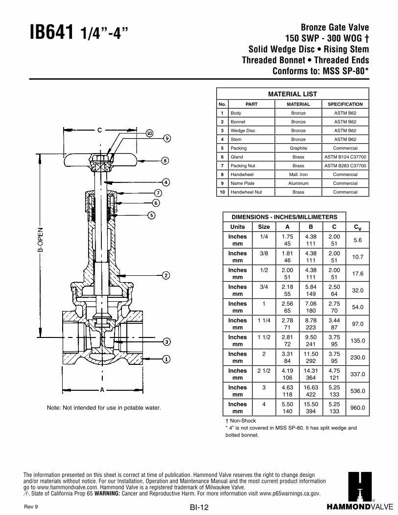
Bronze Gate Valve150 SWP - 300 WOG †
Solid Wedge Disc • Rising StemThreaded Bonnet • Threaded Ends
Conforms to: MSS SP-80*
IB641 1/4”-4”
Note: Not intended for use in potable water.
DIMENSIONS - INCHES/MILLIMETERS
Units Size A B C CvInches
mm1/4 1.75
454.38111
2.0051
5.6
Inchesmm
3/8 1.8146
4.38111
2.0051
10.7
Inchesmm
1/2 2.0051
4.38111
2.0051
17.6
Inchesmm
3/4 2.1855
5.84149
2.5064
32.0
Inchesmm
1 2.5665
7.06180
2.7570
54.0
Inchesmm
1 1/4 2.7871
8.78223
3.4487
97.0
Inchesmm
1 1/2 2.8172
9.50241
3.7595
135.0
Inchesmm
2 3.3184
11.50292
3.7595
230.0
Inchesmm
2 1/2 4.19106
14.31364
4.75121
337.0
Inchesmm
3 4.63118
16.63422
5.25133
536.0
Inchesmm
4 5.50140
15.50394
5.25133
960.0
† Non-Shock* 4” is not covered in MSS SP-80. It has split wedge and bolted bonnet.
MATERIAL LISTNo. PART MATERIAL SPECIFICATION
1 Body Bronze ASTM B62
2 Bonnet Bronze ASTM B62
3 Wedge Disc Bronze ASTM B62
4 Stem Bronze ASTM B62
5 Packing Graphite Commercial
6 Gland Brass ASTM B124 C37700
7 Packing Nut Brass ASTM B283 C37700
8 Handwheel Mall. Iron Commercial
9 Name Plate Aluminum Commercial
10 Handwheel Nut Brass Commercial
Rev 9

The information presented on this sheet is correct at time of publication. Hammond Valve reserves the right to change design and/or materials without notice. For our Installation, Operation and Maintenance Manual and the most current product information go to www.hammondvalve.com. Hammond Valve is a registered trademark of Milwaukee Valve.
State of California Prop 65 WARNING: Cancer and Reproductive Harm. For more information visit www.p65warnings.ca.gov.
BI-13
Bronze Gate Valve150 SWP - 300 WOG †
Solid Wedge Disc • Rising StemUnion Bonnet • Threaded Ends
Conforms to: MSS SP-80
IB629 1/4”-3”
Note: Not intended for use in potable water.
DIMENSIONS - INCHES/MILLIMETERS
Units Size A B C CvInches
mm1/4 1.75
455.13130
2.0051
5.6
Inchesmm
3/8 1.8848
5.13130
2.0051
10.7
Inchesmm
1/2 2.1354
5.50140
2.5064
17.6
Inchesmm
3/4 2.2557
6.25159
2.7570
32.0
Inchesmm
1 2.5665
7.19183
2.7570
54.0
Inchesmm
1 1/4 2.7871
8.56218
3.4487
97.0
Inchesmm
1 1/2 3.2583
9.63245
3.7595
135.0
Inchesmm
2 3.6392
11.75299
4.25108
230.0
Inchesmm
2 1/2 4.50114
14.50368
4.75121
337.0
Inchesmm
3 4.88124
16.75426
5.25133
536.0
† Non-Shock
MATERIAL LISTNo. PART MATERIAL SPECIFICATION
1 Body Bronze ASTM B62
2 Bonnet Bronze ASTM B62
3 Wedge Disc Bronze ASTM B62
4 Stem Bronze ASTM B62
5 Union Bonnet Nut Bronze ASTM B62
6 Packing Graphite Commercial
7 Gland Brass ASTM B124 C37700
8 Packing Nut Brass ASTM B283 C37700
9 Handwheel Mall. Iron Commercial
10 Name Plate Aluminum Commercial
11 Handwheel Nut Brass Commercial
Rev 8
The information presented on this sheet is correct at time of publication. Hammond Valve reserves the right to change design and/or materials without notice. For our Installation, Operation and Maintenance Manual and the most current product information go to www.hammondvalve.com. Hammond Valve is a registered trademark of Milwaukee Valve.
State of California Prop 65 WARNING: Cancer and Reproductive Harm. For more information visit www.p65warnings.ca.gov.
BI-14
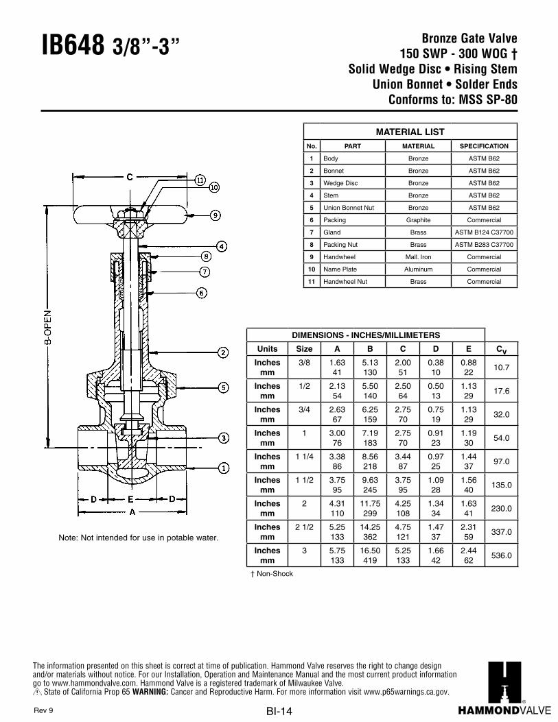
Bronze Gate Valve150 SWP - 300 WOG †
Solid Wedge Disc • Rising StemUnion Bonnet • Solder Ends
Conforms to: MSS SP-80
IB648 3/8”-3”
Note: Not intended for use in potable water.
DIMENSIONS - INCHES/MILLIMETERS
Units Size A B C D E CvInches
mm3/8 1.63
415.13130
2.0051
0.3810
0.8822
10.7
Inchesmm
1/2 2.1354
5.50140
2.5064
0.5013
1.1329
17.6
Inchesmm
3/4 2.6367
6.25159
2.7570
0.7519
1.1329
32.0
Inchesmm
1 3.0076
7.19183
2.7570
0.9123
1.1930
54.0
Inchesmm
1 1/4 3.3886
8.56218
3.4487
0.9725
1.4437
97.0
Inchesmm
1 1/2 3.7595
9.63245
3.7595
1.0928
1.5640
135.0
Inchesmm
2 4.31110
11.75299
4.25108
1.3434
1.6341
230.0
Inchesmm
2 1/2 5.25133
14.25362
4.75121
1.4737
2.3159
337.0
Inchesmm
3 5.75133
16.50419
5.25133
1.6642
2.4462
536.0
† Non-Shock
MATERIAL LISTNo. PART MATERIAL SPECIFICATION
1 Body Bronze ASTM B62
2 Bonnet Bronze ASTM B62
3 Wedge Disc Bronze ASTM B62
4 Stem Bronze ASTM B62
5 Union Bonnet Nut Bronze ASTM B62
6 Packing Graphite Commercial
7 Gland Brass ASTM B124 C37700
8 Packing Nut Brass ASTM B283 C37700
9 Handwheel Mall. Iron Commercial
10 Name Plate Aluminum Commercial
11 Handwheel Nut Brass Commercial
Rev 9
The information presented on this sheet is correct at time of publication. Hammond Valve reserves the right to change design and/or materials without notice. For our Installation, Operation and Maintenance Manual and the most current product information go to www.hammondvalve.com. Hammond Valve is a registered trademark of Milwaukee Valve.
State of California Prop 65 WARNING: Cancer and Reproductive Harm. For more information visit www.p65warnings.ca.gov.
BI-15
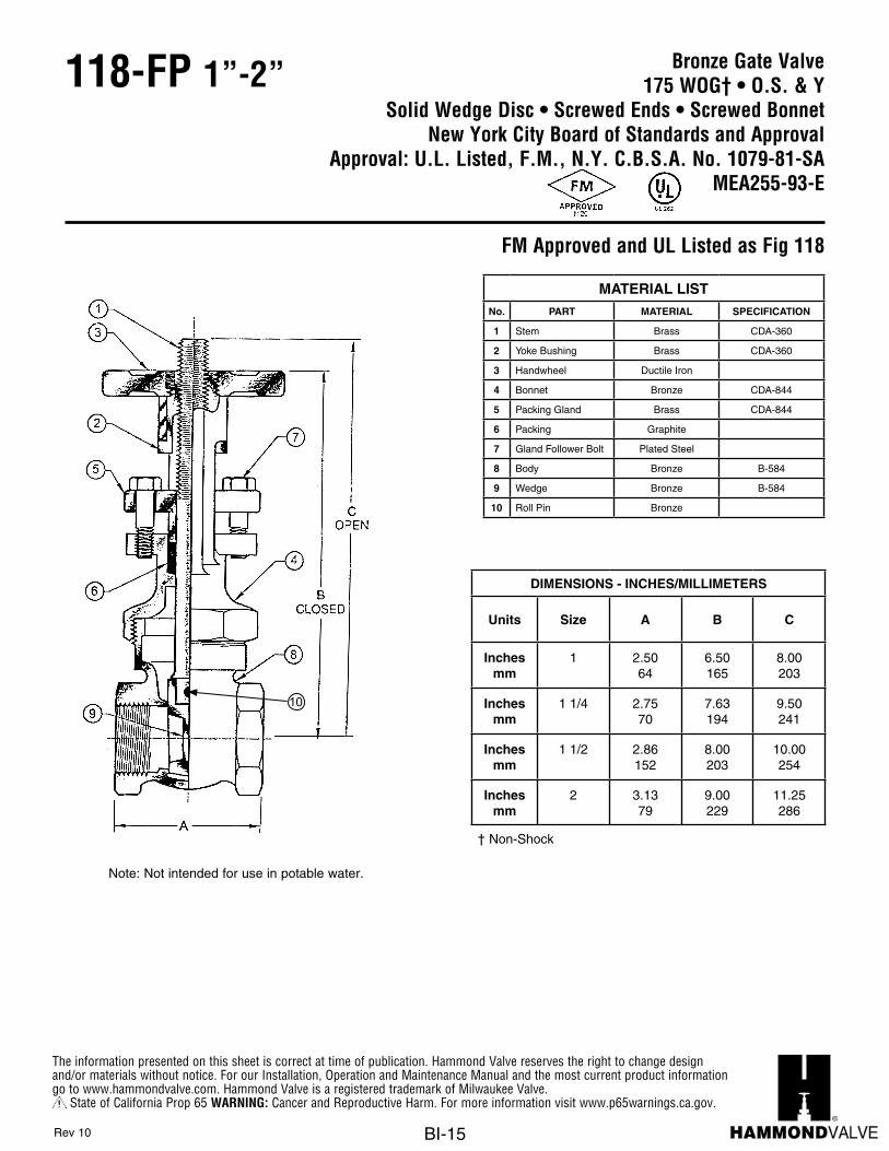
Bronze Gate Valve175 WOG† • O.S. & Y
Solid Wedge Disc • Screwed Ends • Screwed BonnetNew York City Board of Standards and Approval
Approval: U.L. Listed, F.M., N.Y. C.B.S.A. No. 1079-81-SAMEA255-93-E
118-FP 1”-2”
Units Size A B CInches 1 2 1/2 6 1/2 8
MM 25.40 63.50 165.10 203.20Inches 1 1/4 2 3/4 7 5/8 9 1/2
MM 31.75 69.85 193.68 241.30Inches 1 1/2 6 8 10
MM 38.10 152.40 203.20 254.00Inches 2 3 9 11 1/4
MM 50.80 76.20 228.60 285.75
DIMENSIONS - INCHES / MILIMETERS
PART MATERIAL SPECIFICATION1 Stem Brass2 Yoke Bushing Brass3 Handwheel Ductile Iron4 Bonnet Brass5 Packing Gland Brass6 Packing
7 Gland Follower Bolt
8 Body Brass9 Wedge Brass
CDA-844
MATERIAL LIST
Stainless Steel
CDA-360
CDA-844
NO.
† Non-Shock
i - 11
118-FPBRASS GATE
175 WP • O. S. AND Y. • Solid Wedge DiscScrewed Bonnet • Gland Packed • Screwed Ends
www.hammondvalve.com
t Printed on recycled paper with soy ink. 05/05
The information presented on this sheet is correct at the time of publication. Hammond Valve reserves the right to changedesign, and/or material specifications without notice. For the most current information access www.hammondvalve.com
NEW YORK CITY BOARD OF STANDARDS andAPPROVALApprovals: U.L. Listed, F.M.,N.Y.C. B.S.A. No. 1079-81-SA
MEA255-93-E
BETTER AT EVERY TURN
Note: Not intended for use in potable water.
DIMENSIONS - INCHES/MILLIMETERS
Units Size A B C
Inchesmm
1 2.5064
6.50165
8.00203
Inchesmm
1 1/4 2.7570
7.63194
9.50241
Inchesmm
1 1/2 2.86152
8.00203
10.00254
Inchesmm
2 3.1379
9.00229
11.25286
† Non-Shock
MATERIAL LISTNo. PART MATERIAL SPECIFICATION
1 Stem Brass CDA-360
2 Yoke Bushing Brass CDA-360
3 Handwheel Ductile Iron
4 Bonnet Bronze CDA-844
5 Packing Gland Brass CDA-844
6 Packing Graphite
7 Gland Follower Bolt Plated Steel
8 Body Bronze B-584
9 Wedge Bronze B-584
10 Roll Pin Bronze
Rev 10
10
FM Approved and UL Listed as Fig 118
The information presented on this sheet is correct at time of publication. Hammond Valve reserves the right to change design and/or materials without notice. For our Installation, Operation and Maintenance Manual and the most current product information go to www.hammondvalve.com. Hammond Valve is a registered trademark of Milwaukee Valve.
State of California Prop 65 WARNING: Cancer and Reproductive Harm. For more information visit www.p65warnings.ca.gov.
BI-16
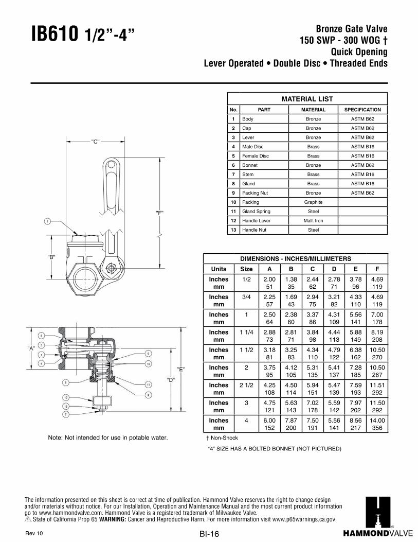
Bronze Gate Valve150 SWP - 300 WOG †
Quick Opening Lever Operated • Double Disc • Threaded Ends
IB610 1/2”-4”
Note: Not intended for use in potable water.
DIMENSIONS - INCHES/MILLIMETERS
Units Size A B C D E F
Inchesmm
1/2 2.0051
1.3835
2.4462
2.7871
3.7896
4.69119
Inchesmm
3/4 2.2557
1.6943
2.9475
3.2182
4.33110
4.69119
Inchesmm
1 2.5064
2.3860
3.3786
4.31109
5.56141
7.00178
Inchesmm
1 1/4 2.8873
2.8171
3.8498
4.44113
5.88149
8.19208
Inchesmm
1 1/2 3.1881
3.2583
4.34110
4.79122
6.38162
10.50270
Inchesmm
2 3.7595
4.12105
5.31135
5.41137
7.28185
10.50267
Inchesmm
2 1/2 4.25108
4.50114
5.94151
5.47139
7.59193
11.51292
Inchesmm
3 4.75121
5.63143
7.02178
5.59142
7.97202
11.50292
Inchesmm
4 6.00152
7.87200
7.50191
5.56141
8.56217
14.00356
† Non-Shock
*4” SIZE HAS A BOLTED BONNET (NOT PICTURED)
MATERIAL LISTNo. PART MATERIAL SPECIFICATION
1 Body Bronze ASTM B62
2 Cap Bronze ASTM B62
3 Lever Bronze ASTM B62
4 Male Disc Brass ASTM B16
5 Female Disc Brass ASTM B16
6 Bonnet Bronze ASTM B62
7 Stem Brass ASTM B16
8 Gland Brass ASTM B16
9 Packing Nut Bronze ASTM B62
10 Packing Graphite
11 Gland Spring Steel
12 Handle Lever Mall. Iron
13 Handle Nut Steel
Rev 10

The information presented on this sheet is correct at time of publication. Hammond Valve reserves the right to change design and/or materials without notice. For our Installation, Operation and Maintenance Manual and the most current product information go to www.hammondvalve.com. Hammond Valve is a registered trademark of Milwaukee Valve.
State of California Prop 65 WARNING: Cancer and Reproductive Harm. For more information visit www.p65warnings.ca.gov.
BI-17
Bronze Gate Valve200 SWP - 400 WOG †
Solid Wedge Disc • Rising StemUnion Bonnet • Threaded Ends • Cu-Ni Seat
Conforms to: MSS SP-80
Note: Not intended for use in potable water.
IB650 1/4”-2”
DIMENSIONS - INCHES/MILLIMETERS
Units Size A B C CvInches
mm1/4 1.81
465.13130
2.0051
5.6
Inchesmm
3/8 1.8848
5.13130
2.0051
10.7
Inchesmm
1/2 2.2557
5.50140
2.5064
17.6
Inchesmm
3/4 2.5064
6.25159
2.7570
32.0
Inchesmm
1 2.8873
7.19183
2.7570
54.0
Inchesmm
1 1/4 3.2583
8.56218
3.4487
97.0
Inchesmm
1 1/2 3.5089
9.56243
3.7595
135.0
Inchesmm
2 3.7595
11.75299
4.25108
230.0
† Non-Shock
MATERIAL LISTNo. PART MATERIAL SPECIFICATION
1 Body Bronze ASTM B61
2 Bonnet Bronze ASTM B61
3 Wedge Disc Bronze ASTM B61
4 Stem Bronze ASTM B61
5 Union Bonnet Nut Bronze ASTM B61
6 Seat Ring Cu-Ni 90-10
7 Packing Graphite Commercial
8 Gland Brass ASTM B 124 C37700
9 Packing Nut Brass ASTM B 283 C37700
10 Handwheel Mall. Iron Commercial
11 Name Plate Aluminum Commercial
12 Handwheel Nut Brass Commercial
Rev 9
The information presented on this sheet is correct at time of publication. Hammond Valve reserves the right to change design and/or materials without notice. For our Installation, Operation and Maintenance Manual and the most current product information go to www.hammondvalve.com. Hammond Valve is a registered trademark of Milwaukee Valve.
State of California Prop 65 WARNING: Cancer and Reproductive Harm. For more information visit www.p65warnings.ca.gov.
BI-18
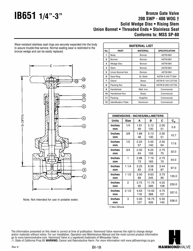
Bronze Gate Valve200 SWP - 400 WOG †
Solid Wedge Disc • Rising StemUnion Bonnet • Threaded Ends • Stainless Seat
Conforms to: MSS SP-80
IB651 1/4”-3”
Wear-resistant stainless seat rings are securely expanded into the body to assure trouble-free service. Normal seating wear is restricted to the bronze wedge and can be easily replaced.
Note: Not intended for use in potable water.
DIMENSIONS - INCHES/MILLIMETERS
Units Size A B C CvInches
mm1/4 1.81
465.13130
2.0051
5.6
Inchesmm
3/8 1.8848
5.13130
2.0051
10.7
Inchesmm
1/2 2.2557
5.50140
2.5064
17.6
Inchesmm
3/4 2.5064
6.25159
2.7570
32.0
Inchesmm
1 2.8873
7.19183
2.7570
54.0
Inchesmm
1 1/4 3.2583
8.56218
3.4487
97.0
Inchesmm
1 1/2 3.5089
9.63245
3.7595
135.0
Inchesmm
2 3.7595
11.75299
4.25108
230.0
Inchesmm
2 1/2 4.63118
14.50368
4.75121
337.0
Inchesmm
3 5.00127
16.75426
5.50140
536.0
† Non-Shock
MATERIAL LISTNo. PART MATERIAL SPECIFICATION
1 Body Bronze ASTM B61
2 Bonnet Bronze ASTM B61
3 Wedge Disc Bronze ASTM B61
4 Stem Bronze ASTM B61
5 Union Bonnet Nut Bronze ASTM B61
6 Seat Ring St. Steel ASTM A 240 TY304
7 Gland Brass ASTM B 124 C37700
8 Packing Nut Brass ASTM B 283 C37700
9 Handwheel Mall. Iron Commercial
10 Handwheel Nut Brass Commercial
11 Packing Graphite Commercial
12 Identification Plate Aluminum Commercial
Rev 9
12

The information presented on this sheet is correct at time of publication. Hammond Valve reserves the right to change design and/or materials without notice. For our Installation, Operation and Maintenance Manual and the most current product information go to www.hammondvalve.com. Hammond Valve is a registered trademark of Milwaukee Valve.
State of California Prop 65 WARNING: Cancer and Reproductive Harm. For more information visit www.p65warnings.ca.gov.
BI-19
Bronze Gate Valve300 SWP - 1000 WOG †
Solid Wedge Disc • Rising StemUnion Bonnet • Threaded Ends • Cu-Ni Seat
Conforms to: MSS SP-80
IB652 1/4”-2”
Note: Not intended for use in potable water.
DIMENSIONS - INCHES/MILLIMETERS
Units Size A B C CvInches
mm1/4 1.81
465.13130
2.0051
5.6
Inchesmm
3/8 1.8848
5.13130
2.0051
10.7
Inchesmm
1/2 2.2557
5.50140
2.5064
17.6
Inchesmm
3/4 2.5064
6.25159
2.7570
32.0
Inchesmm
1 3.0076
7.19183
2.7570
54.0
Inchesmm
1 1/4 3.3886
8.56218
3.4487
97.0
Inchesmm
1 1/2 3.5089
9.63245
3.7595
135.0
Inchesmm
2 3.7595
11.75299
4.25108
230.0
† Non-Shock
MATERIAL LISTNo. PART MATERIAL SPECIFICATION
1 Body Bronze ASTM B61
2 Bonnet Bronze ASTM B61
3 Wedge Disc Bronze ASTM B61
4 Stem Bronze ASTM B61
5 Union Bonnet Nut Bronze ASTM B61
6 Seat Ring Cu-Ni 90-10
7 Gland Brass ASTM B 124 C37700
8 Packing Nut Brass ASTM B 283 C37700
9 Handwheel Mall. Iron Commercial
10 Name Plate Aluminum Commercial
11 Handwheel Nut Brass Commercial
12 Packing Graphite Commercial
Rev 9
10

The information presented on this sheet is correct at time of publication. Hammond Valve reserves the right to change design and/or materials without notice. For our Installation, Operation and Maintenance Manual and the most current product information go to www.hammondvalve.com. Hammond Valve is a registered trademark of Milwaukee Valve.
State of California Prop 65 WARNING: Cancer and Reproductive Harm. For more information visit www.p65warnings.ca.gov.
BI-20
Bronze Gate Valve300 SWP - 1000 WOG †
Solid Wedge Disc • Rising StemUnion Bonnet • Threaded Ends • Stainless Seat
Conforms to: MSS SP-80
IB654 1/4”-3”
Wear-resistant stainless seat rings are securely expanded into the body to assure trouble-free service. Normal seating wear is restricted to the bronze wedge and can be easily replaced.
Note: Not intended for use in potable water.
DIMENSIONS - INCHES/MILLIMETERS
Units Size A B C CvInches
mm1/4 1.81
465.13130
2.0051 5.6
Inchesmm
3/8 1.8848
5.13130
2.0051 10.7
Inchesmm
1/2 2.2557
5.50140
2.5064 17.6
Inchesmm
3/4 2.5064
6.25159
2.7570 32.0
Inchesmm
1 3.0076
7.19183
2.7570 54.0
Inchesmm
1 1/4 3.3886
8.56218
3.4487 97.0
Inchesmm
1 1/2 3.5089
9.63245
3.7595 135.0
Inchesmm
2 3.7595
11.75299
4.25108 230.0
Inchesmm
2 1/2 4.63118
14.50368
4.75121 337.0
Inchesmm
3 5.00127
16.75426
5.50140 536.0
† Non-Shock
MATERIAL LISTNo. PART MATERIAL SPECIFICATION
1 Body Bronze ASTM B61
2 Bonnet Bronze ASTM B61
3 Wedge Disc Bronze ASTM B61
4 Stem Bronze ASTM B61
5 Union Bonnet Nut Bronze ASTM B61
6 Seat Ring St. Steel ASTM A 240 TY304
7 Gland Brass ASTM B 124 C37700
8 Packing Nut Brass ASTM B 283 C37700
9 Handwheel Mall. Iron Commercial
10 Name Plate Aluminum Commercial
11 Handwheel Nut Brass Commercial
12 Packing Graphite Commercial
Rev 9
10

The information presented on this sheet is correct at time of publication. Hammond Valve reserves the right to change design and/or materials without notice. For our Installation, Operation and Maintenance Manual and the most current product information go to www.hammondvalve.com. Hammond Valve is a registered trademark of Milwaukee Valve.
State of California Prop 65 WARNING: Cancer and Reproductive Harm. For more information visit www.p65warnings.ca.gov.
BI-21
Bronze Gate Valve300 SWP - 1000 WOG †
Solid Wedge Disc • Non-Rising StemUnion Bonnet • Threaded Ends • Stainless Seat
Conforms to: MSS SP-80
IB656 1/4”-2”
Wear-resistant stainless seat rings are securely expanded into the body to assure trouble-free service. Normal seating wear is restricted to the bronze wedge and can be easily replaced.
Note: Not intended for use in potable water.
DIMENSIONS - INCHES/MILLIMETERS
Units Size A B C CvInches
mm1/4 1.81
464.13105
2.0051
5.6
Inchesmm
3/8 1.8848
4.13105
2.0051
10.7
Inchesmm
1/2 2.2557
4.31110
2.5064
17.6
Inchesmm
3/4 2.5064
4.56116
2.7570
32.0
Inchesmm
1 3.0076
5.19132
2.7570
54.0
Inchesmm
1 1/4 3.3886
5.94151
3.4487
97.0
Inchesmm
1 1/2 3.5089
6.38162
3.7595
135.0
Inchesmm
2 3.7595
7.69195
4.25108
230.0
† Non-Shock
MATERIAL LISTNo. PART MATERIAL SPECIFICATION
1 Body Bronze ASTM B61
2 Bonnet Bronze ASTM B61
3 Wedge Disc Bronze ASTM B61
4 Stem Bronze ASTM B61
5 Stuffing Box Bronze ASTM B61
6 Union Bonnet Nut Bronze ASTM B61
7 Seat Ring St. Steel ASTM A 240 TY304
8 Packing Graphite Commercial
9 Gland Brass ASTM B 124 C37700
10 Packing Nut Brass ASTM B 283 C37700
11 Handwheel Mall. Iron Commercial
12 Handwheel Nut Brass Commercial
13 Name Plate Aluminum Commercial
Rev 10
13

The information presented on this sheet is correct at time of publication. Hammond Valve reserves the right to change design and/or materials without notice. For our Installation, Operation and Maintenance Manual and the most current product information go to www.hammondvalve.com. Hammond Valve is a registered trademark of Milwaukee Valve.
State of California Prop 65 WARNING: Cancer and Reproductive Harm. For more information visit www.p65warnings.ca.gov.
BI-22
Bronze Globe Valve125 SWP - 200 WOG †
Bronze Disc Threaded Bonnet • Threaded Ends
Conforms to: MSS SP-80
IB440 1/8”-3”
MATERIAL LISTNo. PART MATERIAL SPECIFICATION
1 Body Bronze ASTM B62
2 Bonnet Bronze ASTM B62
3 Disc Bronze ASTM B62
4 Stem Bronze ASTM B16
5 Disc Ring Brass
ASTM B163/4” to 2”
ASTM B622 1/2” and 3”
6 Packing Graphite Commercial
7 Packing Nut Brass ASTM B16
8 Handwheel Mall. Iron Commercial
9 Name Plate Aluminum Commercial
10 Handwheel Nut Brass Commercial
11 Gland (not shown) BrassASTM B16
2 1/2” and 3” only
1/8” to 1/2” sizes have the disc integral with the stem and have no disc ring.
Rev 9
8
9
10
Note: Not intended for use in potable water.
DIMENSIONS - INCHES/MILLIMETERS
Units Size A B C CvInches
mm1/8 1.63
413.0678
2.0051 0.61
Inchesmm
1/4 1.6341
3.0678
2.0051 1.16
Inchesmm
3/8 1.8146
3.1981
2.0051 2.21
Inchesmm
1/2 2.3159
3.6392
2.2557 3.64
Inchesmm
3/4 2.5665
3.94100
2.5064 6.65
Inchesmm
1 2.9475
4.38111
2.7570 11.10
Inchesmm
1 1/4 3.3886
5.19132
3.1379 20.00
Inchesmm
1 1/2 3.6994
5.75146
3.5089 28.00
Inchesmm
2 4.44113
6.75172
4.00102 48.00
Inchesmm
2 1/2 5.75146
8.63219
4.75121 70.00
Inchesmm
3 6.88175
9.25235
5.50140 111.00
† Non-Shock

The information presented on this sheet is correct at time of publication. Hammond Valve reserves the right to change design and/or materials without notice. For our Installation, Operation and Maintenance Manual and the most current product information go to www.hammondvalve.com. Hammond Valve is a registered trademark of Milwaukee Valve.
State of California Prop 65 WARNING: Cancer and Reproductive Harm. For more information visit www.p65warnings.ca.gov.
BI-23
Bronze Globe Valve200 psig @ 250°F †
Bronze Disc Threaded Bonnet • Press Ends
Conforms to: MSS SP-80
IB440 P2 1/2”-2”
C
M
Y
CM
MY
CY
CMY
K
Drawing.pdf 1 3/30/16 8:22 PM
Press End Adapter (4151 Series)
12
With Press Ends
DIMENSIONS - INCHES/MILLIMETERS
Units SizeSTD
Insertion Depth
A B C Cv
Inchesmm
1/2 0.8722
5.31135
3.6392
2.2557
3.64
Inchesmm
3/4 0.98166
6.14156
3.94100
2.5064
6.65
Inchesmm
1 0.98166
6.94176
4.38111
2.7570
11.10
Inchesmm
1 1/4 1.0226
7.45189
5.19132
3.1379
20.00
Inchesmm
1 1/2 1.4236
8.17208
5.75146
3.5089
28.00
Inchesmm
2 1.5840
10.44265
6.75172
4.00102
48.00
† Non-Shock
MATERIAL LISTNo. PART MATERIAL SPECIFICATION
1 Body Bronze ASTM B62
2 Bonnet Bronze ASTM B62
3 Disc Bronze ASTM B62
4 Stem Bronze ASTM B16
5 Disc Ring BrassASTM B163/4” to 2”
6 Packing Graphite Commercial
7 Packing Nut Brass ASTM B16
8 Handwheel Mall. Iron Commercial
9 Name Plate Aluminum Commercial
10 Handwheel Nut Brass Commercial
11 Gland (not shown) Brass ASTM B16
12 Press Adapter Brass Fitted W/EPDM O-Ring ASTM C27450
1/2” size has the disc integral with the stem and have no disc ring.
Rev 2
810
Note: Not intended for use in potable water.

The information presented on this sheet is correct at time of publication. Hammond Valve reserves the right to change design and/or materials without notice. For our Installation, Operation and Maintenance Manual and the most current product information go to www.hammondvalve.com. Hammond Valve is a registered trademark of Milwaukee Valve.
State of California Prop 65 WARNING: Cancer and Reproductive Harm. For more information visit www.p65warnings.ca.gov.
BI-24
Bronze Globe Valve125 SWP - 200 WOG †
Bronze Disc Threaded Bonnet • Solder Ends
Conforms to: MSS SP-80
IB418 3/8”-2”
DIMENSIONS - INCHES/MILLIMETERS
Units Size A B C D E CvInches
mm3/8 1.94
493.1982
2.0051
0.3810
1.1830
2.21
Inchesmm
1/2 2.4462
3.7595
2.0051
0.5013
1.4437
3.64
Inchesmm
3/4 3.1981
4.00102
2.5064
0.7519
1.6943
6.65
Inchesmm
1 3.6994
4.38111
2.7570
0.9123
1.8843
11.10
Inchesmm
1 1/4 4.19106
5.13130
3.4487
0.9725
2.2557
20.00
Inchesmm
1 1/2 4.75121
5.63143
3.7595
1.0928
2.5665
28.00
Inchesmm
2 5.94151
6.69170
4.25121
1.3434
3.2583
48.00
† Non-Shock
MATERIAL LISTNo. PART MATERIAL SPECIFICATION
1 Body Bronze ASTM B62
2 Bonnet Bronze ASTM B62
3 Disc* Bronze ASTM B62
4 Stem Bronze ASTM B16
5 Disc Ring BrassASTM B16
3/4” to 2” Incl.
6 Packing Graphite Commercial
7 Packing Nut Brass ASTM B16
8 Handwheel Mall. Iron Commercial
9 Name Plate Aluminum Commercial
10 Handwheel Nut Brass Commercial
* 3/8” and 1/2” sizes have the disc integral with the stem and have no disc ring. 3/4” - 1 1/4” sizes Disc material is ASTM B453 C34500
Rev 12
Note: Not intended for use in potable water.
5

The information presented on this sheet is correct at time of publication. Hammond Valve reserves the right to change design and/or materials without notice. For our Installation, Operation and Maintenance Manual and the most current product information go to www.hammondvalve.com. Hammond Valve is a registered trademark of Milwaukee Valve.
State of California Prop 65 WARNING: Cancer and Reproductive Harm. For more information visit www.p65warnings.ca.gov.
BI-25
Bronze Globe Valve150 SWP - 300 WOG †
Teflon DiscUnion Bonnet • Threaded Ends
Conforms to: MSS SP-80
IB413T 1/8”-3”
Note: Not intended for use in potable water.
DIMENSIONS - INCHES/MILLIMETERS
Units Size A B C CvInches
mm1/8 2.06
523.94100
2.0051 0.61
Inchesmm
1/4 2.0652
3.94100
2.0051 1.16
Inchesmm
3/8 2.0652
4.25108
2.0051 2.21
Inchesmm
1/2 2.4462
4.56116
2.5064 3.64
Inchesmm
3/4 2.9475
5.19132
2.7570 6.65
Inchesmm
1 3.4487
5.50140
3.4487 11.10
Inchesmm
1 1/4 3.8898
6.25159
3.7595 20.00
Inchesmm
1 1/2 4.50114
7.13181
3.7595 28.00
Inchesmm
2 5.75146
8.88226
4.75121 48.00
Inchesmm
2 1/2 6.75172
10.63270
5.50140 70.00
Inchesmm
3 8.00203
12.13308
6.00152 111.00
† Non-Shock
MATERIAL LISTNo. PART MATERIAL SPECIFICATION
1 Body Bronze ASTM B62
2 Bonnet Bronze ASTM B62
3 Disc Teflon
4 Stem Bronze ASTM B62
5 Disc Holder Bronze
ASTM B161/4” to 3/4”ASTM B62
1” to 3”
6 Union Bonnet Nut Bronze ASTM B62
7 Packing Graphite Commercial
8 Gland Brass ASTM B 124 C37700
9 Packing Nut Brass ASTM B 283 C37700
10 Disc Nut Bronze Commercial
11 Handwheel Mall. Iron Commercial
12 Name Plate Aluminum Commercial
13 Handwheel Nut Brass Commercial
Rev 9
10

The information presented on this sheet is correct at time of publication. Hammond Valve reserves the right to change design and/or materials without notice. For our Installation, Operation and Maintenance Manual and the most current product information go to www.hammondvalve.com. Hammond Valve is a registered trademark of Milwaukee Valve.
State of California Prop 65 WARNING: Cancer and Reproductive Harm. For more information visit www.p65warnings.ca.gov.
BI-26
C
M
Y
CM
MY
CY
CMY
K
Drawing.pdf 1 3/30/16 8:22 PM
Press End Adapter (4151 Series)
14
Bronze Globe Valve200 psig @ 250°F †
Teflon DiscUnion Bonnet • Press Ends
Conforms to: MSS SP-80
IB413T P2 1/2”-2”
MATERIAL LISTNo. PART MATERIAL SPECIFICATION
1 Body Bronze ASTM B62
2 Bonnet Bronze ASTM B62
3 Disc Teflon
4 Stem Bronze ASTM B62
5 Disc Holder Bronze
ASTM B161/4” to 3/4”ASTM B62
1” to 2”
6 Union Bonnet Nut Bronze ASTM B62
7 Packing Graphite Commercial
8 Gland Brass ASTM B 124 C37700
9 Packing Nut Brass ASTM B 124 C37700
10 Disc Nut Bronze Commercial
11 Handwheel Mall. Iron Commercial
12 Name Plate Aluminum Commercial
13 Handwheel Nut Brass Commercial
14 Press Adapters Brass Fitted W/EPDM O-Ring ASTM C27450
Rev 3
10
With Press Ends
Note: Not intended for use in potable water.
DIMENSIONS - INCHES/MILLIMETERS
Units SizeSTD
Insertion Depth
A B C Cv
Inchesmm
1/2 0.8722
5.44138
4.56116
2.5064
3.64
Inchesmm
3/4 0.9825
6.52166
5.19132
2.7570
6.65
Inchesmm
1 0.9825
7.44189
5.50140
3.4487
11.10
Inchesmm
1 1/4 1.0226
7.95202
6.25159
3.7595
20.00
Inchesmm
1 1/2 1.4236
8.98228
7.13181
3.7595
28.00
Inchesmm
2 1.5840
11.75298
8.88226
4.75121
48.00
† Non-Shock

The information presented on this sheet is correct at time of publication. Hammond Valve reserves the right to change design and/or materials without notice. For our Installation, Operation and Maintenance Manual and the most current product information go to www.hammondvalve.com. Hammond Valve is a registered trademark of Milwaukee Valve.
State of California Prop 65 WARNING: Cancer and Reproductive Harm. For more information visit www.p65warnings.ca.gov.
BI-27
Bronze Globe Valve150 SWP - 300 WOG †
Teflon DiscUnion Bonnet • Solder Ends
Conforms to: MSS SP-80
IB423 1/2”-3”
DIMENSIONS - INCHES/MILLIMETERS
Units Size A B C D E CvInches
mm1/2 2.75
704.50114
2.5064
0.5013
1.7545
3.64
Inchesmm
3/4 3.5691
5.19132
2.7570
0.7519
2.0652
6.65
Inchesmm
1 4.38111
5.50140
3.4487
0.9123
2.5665
11.10
Inchesmm
1 1/4 5.00127
6.25159
3.7595
0.9725
3.0678
20.00
Inchesmm
1 1/2 5.88149
7.13181
3.7595
1.0928
3.7094
28.00
Inchesmm
2 7.06179
8.88225
4.75121
1.3434
4.38111
48.00
Inchesmm
2 1/2 8.1964
10.63270
5.50140
1.4737
5.25133
70.00
Inchesmm
3 9.56243
12.13308
6.00152
1.6642
6.25159
111.00
† Non-Shock
MATERIAL LISTNo. PART MATERIAL SPECIFICATION
1 Body Bronze ASTM B62
2 Bonnet Bronze ASTM B62
3 Disc Teflon
4 Stem Bronze ASTM B62
5 Disc Holder Bronze ASTM B62
6 Union Bonnet Nut Bronze ASTM B62
7 Packing Graphite Commercial
8 Gland Brass ASTM B16
9 Packing Nut
Brass 1/2”-1 1/4” ASTM B16
Bronze 1 1/2"-3"ASTM B584 or
ASTM B62
10 Disc Nut Brass ASTM B16
11 Handwheel Mall. Iron Commercial
12 Name Plate Aluminum Commercial
13 Handwheel Nut Brass ASTM B16
Rev 11
Note: Not intended for use in potable water.
10
12
1113
The information presented on this sheet is correct at time of publication. Hammond Valve reserves the right to change design and/or materials without notice. For our Installation, Operation and Maintenance Manual and the most current product information go to www.hammondvalve.com. Hammond Valve is a registered trademark of Milwaukee Valve.
State of California Prop 65 WARNING: Cancer and Reproductive Harm. For more information visit www.p65warnings.ca.gov.
BI-28
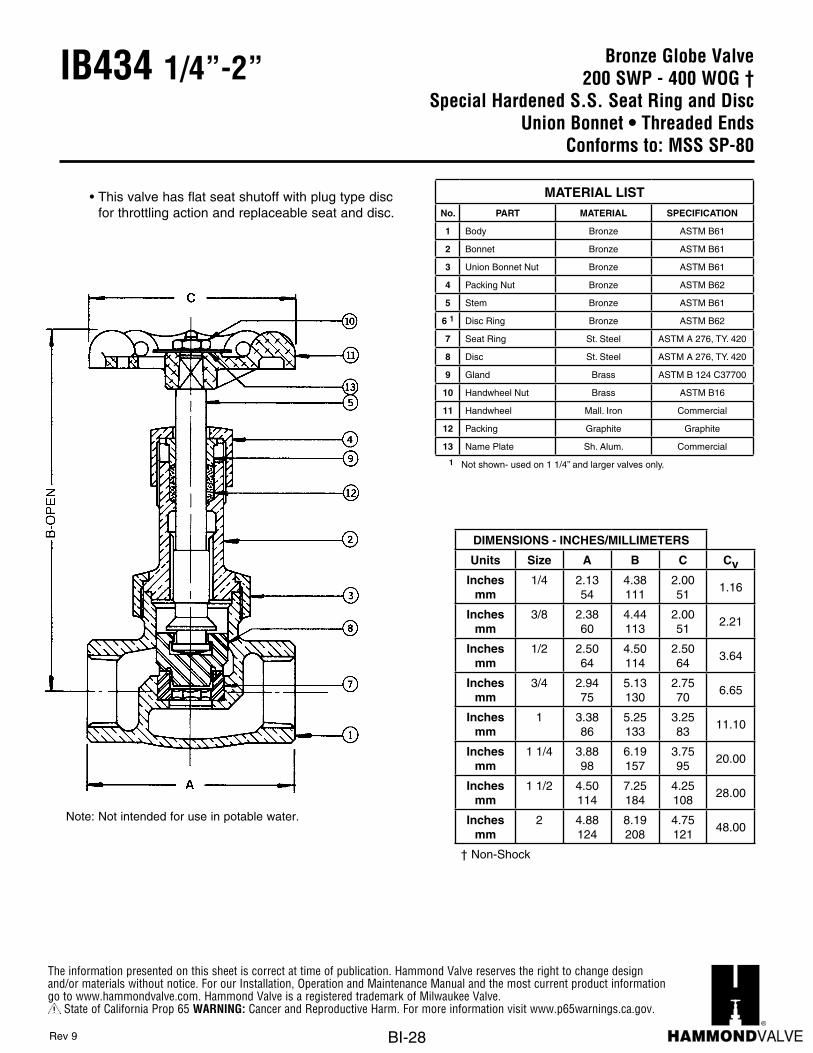
Bronze Globe Valve200 SWP - 400 WOG †
Special Hardened S.S. Seat Ring and DiscUnion Bonnet • Threaded Ends
Conforms to: MSS SP-80
IB434 1/4”-2”
• This valve has flat seat shutoff with plug type disc for throttling action and replaceable seat and disc.
Note: Not intended for use in potable water.
DIMENSIONS - INCHES/MILLIMETERS
Units Size A B C CvInches
mm1/4 2.13
544.38111
2.0051
1.16
Inchesmm
3/8 2.3860
4.44113
2.0051
2.21
Inchesmm
1/2 2.5064
4.50114
2.5064
3.64
Inchesmm
3/4 2.9475
5.13130
2.7570
6.65
Inchesmm
1 3.3886
5.25133
3.2583
11.10
Inchesmm
1 1/4 3.8898
6.19157
3.7595
20.00
Inchesmm
1 1/2 4.50114
7.25184
4.25108
28.00
Inchesmm
2 4.88124
8.19208
4.75121
48.00
† Non-Shock
MATERIAL LISTNo. PART MATERIAL SPECIFICATION
1 Body Bronze ASTM B61
2 Bonnet Bronze ASTM B61
3 Union Bonnet Nut Bronze ASTM B61
4 Packing Nut Bronze ASTM B62
5 Stem Bronze ASTM B61
6 1 Disc Ring Bronze ASTM B62
7 Seat Ring St. Steel ASTM A 276, TY. 420
8 Disc St. Steel ASTM A 276, TY. 420
9 Gland Brass ASTM B 124 C37700
10 Handwheel Nut Brass ASTM B16
11 Handwheel Mall. Iron Commercial
12 Packing Graphite Graphite
13 Name Plate Sh. Alum. Commercial
1 Not shown- used on 1 1/4” and larger valves only.
Rev 9

The information presented on this sheet is correct at time of publication. Hammond Valve reserves the right to change design and/or materials without notice. For our Installation, Operation and Maintenance Manual and the most current product information go to www.hammondvalve.com. Hammond Valve is a registered trademark of Milwaukee Valve.
State of California Prop 65 WARNING: Cancer and Reproductive Harm. For more information visit www.p65warnings.ca.gov.
BI-29
Bronze Globe Valve200 SWP - 400 WOG †
Needle Point Bronze StemThreaded Bonnet • Threaded Ends
Conforms to: MSS SP-80
IB415 1/8”-3/4”
Note: Not intended for use in potable water.
DIMENSIONS - INCHES/MILLIMETERS
Units Size A B C
Inchesmm
1/8 1.6341
3.1981
2.0051
Inchesmm
1/4 1.6341
3.1981
2.0051
Inchesmm
3/8 1.8146
3.1981
2.0051
Inchesmm
1/2 2.3159
3.6392
2.0051
Inchesmm
3/4 2.5665
3.94100
2.2557
† Non-Shock
MATERIAL LISTNo. PART MATERIAL SPECIFICATION
1 Body Bronze ASTM B61
2 Bonnet Bronze ASTM B61
3 Stem Bronze ASTM B61
4Seat Ring(Pressed In)
Bronze ASTM B61
5 Packing Nut Graphite
6 Gland Brass ASTM B 124 C37700
7 Packing Nut Brass ASTM B 283 C37700
8 Handwheel Mall. Iron Commercial
9 Name Plate Aluminum Commercial
10 Handwheel Nut Brass Commercial
Rev 8

The information presented on this sheet is correct at time of publication. Hammond Valve reserves the right to change design and/or materials without notice. For our Installation, Operation and Maintenance Manual and the most current product information go to www.hammondvalve.com. Hammond Valve is a registered trademark of Milwaukee Valve.
State of California Prop 65 WARNING: Cancer and Reproductive Harm. For more information visit www.p65warnings.ca.gov.
BI-30
Bronze Globe Valve300 SWP - 1000 WOG †Bronze Renewable Disc
Union Bonnet • Threaded EndsConforms to: MSS SP-80
IB412 1/4”-2”
Note: Not intended for use in potable water.
DIMENSIONS - INCHES/MILLIMETERS
Units Size A B C CvInches
mm1/4 2.06
524.00102
2.0051
1.16
Inchesmm
3/8 2.0652
4.00102
2.0051
2.21
Inchesmm
1/2 2.4462
4.50114
2.5064
3.64
Inchesmm
3/4 2.9475
5.19132
2.7570
6.65
Inchesmm
1 3.7595
6.38162
3.4487
11.10
Inchesmm
1 1/4 4.25108
7.00178
3.7595
20.00
Inchesmm
1 1/2 4.75121
7.75197
4.25108
28.00
Inchesmm
2 5.75146
10.00254
4.75121
48.00
† Non-Shock
MATERIAL LISTNo. PART MATERIAL SPECIFICATION
1 Body Bronze ASTM B61
2 Bonnet Bronze ASTM B61
3 Disc Bronze ASTM B61
4 Stem Bronze ASTM B61
5 Union Bonnet Nut Bronze ASTM B61
6 Packing Graphite Commercial
7 Gland Brass ASTM B 124 C37700
8 Packing Nut Brass ASTM B16
9 Handwheel Mall. Iron Commercial
10 Name Plate Aluminum Commercial
11 Handwheel Nut Brass Commercial
12 Disc Ring Bronze Commercial
1/4” to 1/2” sizes have the disc integral with the stem and have no disc ring
Rev 10

The information presented on this sheet is correct at time of publication. Hammond Valve reserves the right to change design and/or materials without notice. For our Installation, Operation and Maintenance Manual and the most current product information go to www.hammondvalve.com. Hammond Valve is a registered trademark of Milwaukee Valve.
State of California Prop 65 WARNING: Cancer and Reproductive Harm. For more information visit www.p65warnings.ca.gov.
BI-31
Bronze Globe Valve300 SWP - 1000 WOG †
Special Hardened S.S. Seat Ring and DiscUnion Bonnet • Threaded Ends
Conforms to: MSS SP-80
IB444 1/4”-2”
Note: Not intended for use in potable water.
DIMENSIONS - INCHES/MILLIMETERS
Units Size A B C CvInches
mm1/4 2.13
544.38111
2.0051 1.16
Inchesmm
3/8 2.3860
4.44113
2.0051 2.21
Inchesmm
1/2 2.7570
4.50114
2.5064 3.64
Inchesmm
3/4 3.1981
5.13130
2.7570 6.65
Inchesmm
1 3.6392
5.38137
3.2583 11.10
Inchesmm
1 1/4 4.13105
6.25159
3.7595 20.00
Inchesmm
1 1/2 4.75121
7.38187
4.25108 28.00
Inchesmm
2 5.13130
8.38213
4.75121 48.00
† Non-Shock
MATERIAL LISTNo. PART MATERIAL SPECIFICATION
1 Body Bronze ASTM B61
2 Bonnet Bronze ASTM B61
3 Union Bonnet Nut Bronze ASTM B61
4 Packing Nut Bronze ASTM B62
5 Stem Bronze ASTM B61
6 1 Disc Ring Bronze ASTM B62
7 Seat Ring St. Steel ASTM A 276, TY. 420
8 Disc St. Steel ASTM A 276, TY. 420
9 Gland Brass ASTM B16
10 Handwheel Nut Brass ASTM B16
11 Handwheel Mall. Iron Commercial
12 Packing Graphite
13 Name Plate Sh. Alum. Commercial
1 Not shown- used on 1 1/4” and larger valves only.
• This valve has flat seat shutoff with plug type disc for throttling action and replaceable seat and disc.
Rev 8

The information presented on this sheet is correct at time of publication. Hammond Valve reserves the right to change design and/or materials without notice. For our Installation, Operation and Maintenance Manual and the most current product information go to www.hammondvalve.com. Hammond Valve is a registered trademark of Milwaukee Valve.
State of California Prop 65 WARNING: Cancer and Reproductive Harm. For more information visit www.p65warnings.ca.gov.
BI-32
Bronze Angle Valve125 SWP - 200 WOG †
Bronze DiscThreaded Bonnet • Threaded Ends
Conforms to: MSS SP-80
IB463 1/4”-2 1/2”
Note: Not intended for use in potable water.
DIMENSIONS - INCHES/MILLIMETERS
Units Size A B C CvInches
mm1/4 0.75
193.0678
2.0051
1.60
Inchesmm
3/8 0.9123
3.1981
2.0051
3.10
Inchesmm
1/2 1.0025
3.6392
2.2557
5.10
Inchesmm
3/4 1.2532
3.94100
2.5064
9.20
Inchesmm
1 1.4437
4.38111
2.7570
16.00
Inchesmm
1 1/4 1.6943
5.19132
3.1380
28.00
Inchesmm
1 1/2 1.8146
5.75146
3.5089
39.00
Inchesmm
2 2.1956
6.75172
4.00102
66.00
Inchesmm
2 1/2 3.0076
8.63219
4.75121
100.00
† Non-Shock
MATERIAL LISTNo. PART MATERIAL SPECIFICATION
1 Body Bronze ASTM B62
2 Bonnet Bronze ASTM B62
3 Disc Bronze ASTM B62
4 Stem Bronze ASTM B62
5 Disc Ring Brass
ASTM B 163/4” to 2”
ASTM B 622 1/2”
6 Packing Graphite Commercial
7 Packing Nut Brass ASTM B16
8 Handwheel Mall. Iron Commercial
9 Name Plate Aluminum Commercial
10 Handwheel Nut Brass Commercial
11Gland(not shown)
Bronze ASTM B 16
• 1/4” to 1/2” sizes have the disc integral with the stem and have no disc ring.
Rev 8

The information presented on this sheet is correct at time of publication. Hammond Valve reserves the right to change design and/or materials without notice. For our Installation, Operation and Maintenance Manual and the most current product information go to www.hammondvalve.com. Hammond Valve is a registered trademark of Milwaukee Valve.
State of California Prop 65 WARNING: Cancer and Reproductive Harm. For more information visit www.p65warnings.ca.gov.
BI-33
Bronze Angle Valve150 SWP - 300 WOG †
Teflon DiscUnion Bonnet • Threaded Ends
Conforms to: MSS SP-80
IB454T 1/4”-2”
Note: Not intended for use in potable water.
DIMENSIONS - INCHES/MILLIMETERS
Units Size A B C CvInches
mm1/4 1.06
273.94100
2.0051
1.60
Inchesmm
3/8 1.1930
4.25108
2.0051
3.10
Inchesmm
1/2 1.1930
5.13130
2.5064
5.10
Inchesmm
3/4 1.4437
5.19132
2.7570
9.20
Inchesmm
1 1.7545
6.56167
3.2583
16.00
Inchesmm
1 1/4 2.0652
6.25159
3.7595
28.00
Inchesmm
1 1/2 2.2557
7.63194
4.25108
39.00
Inchesmm
2 2.7570
8.88225
4.75121
66.00
† Non-Shock
MATERIAL LISTNo. PART MATERIAL SPECIFICATION
1 Body Bronze ASTM B62
2 Bonnet Bronze ASTM B62
3 Disc Teflon
4 Stem Bronze ASTM B62
5 Disc Ring Brass
ASTM B5051/4” to 3/4” ASTM B 62
1” to 2”
6 Union Bonnet Nut Bronze ASTM B62
7 Packing Graphite Commercial
8 Gland Bronze ASTM B16
9 Packing Nut Bronze Commercial
10 Disc Nut Brass Commercial
11 Handwheel Mall. Iron Commercial
12 Identification Plate Aluminum Commercial
13 Handwheel Nut Brass Commercial
Rev 9
10
13
12
11

The information presented on this sheet is correct at time of publication. Hammond Valve reserves the right to change design and/or materials without notice. For our Installation, Operation and Maintenance Manual and the most current product information go to www.hammondvalve.com. Hammond Valve is a registered trademark of Milwaukee Valve.
State of California Prop 65 WARNING: Cancer and Reproductive Harm. For more information visit www.p65warnings.ca.gov.
BI-34
Brass Check Valve200 psig @ 250°F †
Horizontal Swing, Press Ends969* 1/2”-2”
TM
* Ultra Press Valves are designed and qualified for use in copper tubing systems only, Types K, L, & M per ASTM B88. For installation instructions please see engineering section on website.
Note: Not intended for use in potable water.
DIMENSIONS - INCHES/MILLIMETERS
Units Size A B C D
Inchesmm
1/2 3.3585
1.3835
1.743
0.8321
Inchesmm
3/4 3.7495
1.4336
1.7545
0.9925
Inchesmm
1 4.36111
1.7444
2.3861
0.9925
Inchesmm
1 1/4 4.97126
1.9951
2.9274
1.0226
Inchesmm
1 1/2 6.13156
2.2858
3.384
1.4236
Inchesmm
2 7.16182
2.4863
3.99101
1.5940
MATERIAL LISTNo. PART MATERIAL SPECIFICATION
1 Body Brass ASTM B283, C37700
2 Cap Brass ASTM B283, C37700
3 Disc Brass ASTM B283, C37700
4 O-Ring EPDM D2000 NSF61
5 Pin St. Steel ASTM A276 TY. 304
6 Side Plug Brass ASTM B124, C37700
Rev 5

The information presented on this sheet is correct at time of publication. Hammond Valve reserves the right to change design and/or materials without notice. For our Installation, Operation and Maintenance Manual and the most current product information go to www.hammondvalve.com. Hammond Valve is a registered trademark of Milwaukee Valve.
State of California Prop 65 WARNING: Cancer and Reproductive Harm. For more information visit www.p65warnings.ca.gov.
BI-35
Bronze Check Valve125 SWP - 200 WOG †
Horizontal Swing • Threaded EndsConforms to: MSS SP-80
IB904/IB940 1/4”-3”
Rev 14
Note: Not intended for use in potable water.
DIMENSIONS - INCHES/MILLIMETERS
Units Size A B CvInches
mm1/4 2.13
541.3234 3.3
Inchesmm
3/8 2.1354
1.3234 6.0
Inchesmm
1/2 2.3159
1.3234 10.0
Inchesmm
3/4 2.6367
1.6943 18.0
Inchesmm
1 3.2583
2.0051 31.0
Inchesmm
1 1/4 3.5691
2.1354 54.0
Inchesmm
1 1/2 4.00102
2.3860 76.0
Inchesmm
2 4.75121
2.8171 131.0
Inchesmm
*2 1/2 6.00152
3.6392 233.8
Inchesmm
*3 6.88175
4.19106 286.4
† Non-Shock*2 1/2” and 3” not available in the IB940.
MATERIAL LISTNo. PART MATERIAL SPECIFICATION
1 Body Bronze ASTM B62
2 Cap Bronze ASTM B62
3 Lever
St. Steel-IB904Commercial
1/4” to 2”
Bronze-IB904ASTM B5842 1/2” and 3”
Brass-IB940ASTM B161/4” to 2”
4 Disc
Brass-IB904
ASTM B161/4” to 3/4”
ASTM B4531” to 1 1/2”
Bronze-IB904ASTM B62
2” to 3”
PTFE-IB940 Commercial
5Disc Holder(509T Only)
BrassASTM B161/4” to 3/4”
BronzeASTM B62
1” to 2”
6 Pin St. Steel Commercial
7 Disc Nut Brass ASTM B16
8 Retaining Ring St. Steel Commercial
9 Plug (not shown) Brass ASTM B16
10 Washer (not shown) Brass ASTM B16

The information presented on this sheet is correct at time of publication. Hammond Valve reserves the right to change design and/or materials without notice. For our Installation, Operation and Maintenance Manual and the most current product information go to www.hammondvalve.com. Hammond Valve is a registered trademark of Milwaukee Valve.
State of California Prop 65 WARNING: Cancer and Reproductive Harm. For more information visit www.p65warnings.ca.gov.
BI-36
Bronze Check Valve200 psig @ 250°F †
Horizontal Swing • Press EndsConforms to: MSS SP-80
IB904/IB940 P2 1/2”-2”
Rev 3
DIMENSIONS - INCHES/MILLIMETERS
Units SizeSTD
Insertion Depth
A B Cv
Inchesmm
1/2 0.8722
5.31135
1.3234
10.0
Inchesmm
3/4 0.9825
6.21158
1.6943
18.0
Inchesmm
1 0.9825
7.25184
2.0051
31.0
Inchesmm
1 1/4 1.0226
7.63194
2.1354
54.00
Inchesmm
1 1/2 1.4236
8.48215
2.3860
76.00
Inchesmm
21.5840
10.75273
2.8171
131.00
† Non-Shock
Note: Not intended for use in potable water.
C
M
Y
CM
MY
CY
CMY
K
Drawing.pdf 1 3/30/16 8:22 PM
Press End Adapter (4151 Series)
10
With Press Ends
MATERIAL LISTNo. PART MATERIAL SPECIFICATION
1 Body Bronze ASTM B62
2 Cap Bronze ASTM B62
3 Lever
Stainless Steel IB904 P2Commercial
1/2” to 2”
Brass IB940 P2ASTM B 16
1/2” to 2”
4 Disc
Brass IB904 P2
ASTM B 161/2” to 3/4”
ASTM B 4531” to 1 1/2”
Brone IB904 P2ASTM B62
2”
PTFE IB940 P2 Commercial
5Disc Holder(509T P2 Only)
BrassASTM B161/2” to 3/4”
BronzeASTM B62
1” to 2”
6 Pin St. Steel Commercial
7 Disc Nut Brass ASTM B16
8 Retaining Ring St. Steel Commercial
9 Plug (not shown) Brass ASTM B16
10 Press AdaptersBrass Fitting
w/EPDM O-ringASTM B283
C27450
The information presented on this sheet is correct at time of publication. Hammond Valve reserves the right to change design and/or materials without notice. For our Installation, Operation and Maintenance Manual and the most current product information go to www.hammondvalve.com. Hammond Valve is a registered trademark of Milwaukee Valve.
State of California Prop 65 WARNING: Cancer and Reproductive Harm. For more information visit www.p65warnings.ca.gov.
BI-37
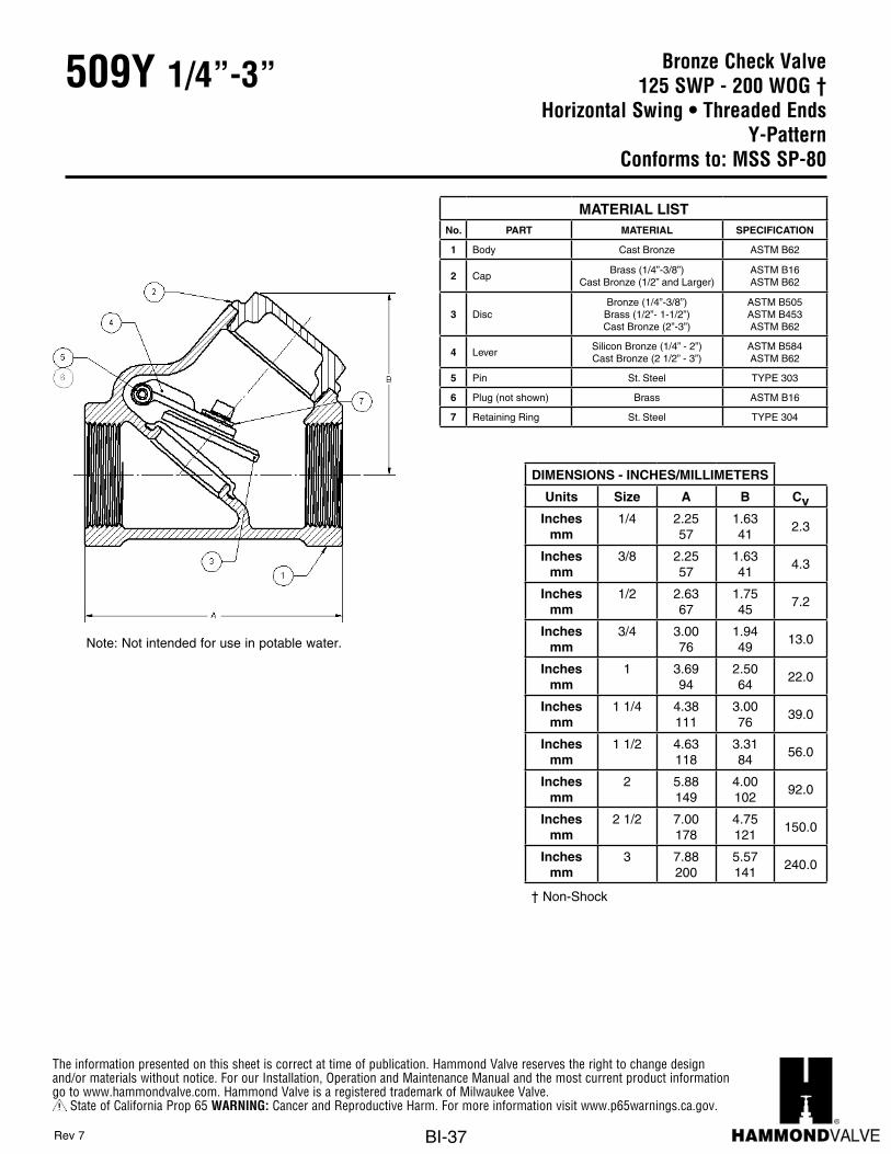
Bronze Check Valve125 SWP - 200 WOG †
Horizontal Swing • Threaded EndsY-Pattern
Conforms to: MSS SP-80
509Y 1/4”-3”
Rev 7
Note: Not intended for use in potable water.
DIMENSIONS - INCHES/MILLIMETERS
Units Size A B CvInches
mm1/4 2.25
571.6341
2.3
Inchesmm
3/8 2.2557
1.6341
4.3
Inchesmm
1/2 2.6367
1.7545
7.2
Inchesmm
3/4 3.0076
1.9449
13.0
Inchesmm
1 3.6994
2.5064
22.0
Inchesmm
1 1/4 4.38111
3.0076
39.0
Inchesmm
1 1/2 4.63118
3.3184
56.0
Inchesmm
2 5.88149
4.00102
92.0
Inchesmm
2 1/2 7.00178
4.75121
150.0
Inchesmm
3 7.88200
5.57141
240.0
† Non-Shock
MATERIAL LISTNo. PART MATERIAL SPECIFICATION
1 Body Cast Bronze ASTM B62
2 CapBrass (1/4”-3/8”)
Cast Bronze (1/2” and Larger)ASTM B16ASTM B62
3 DiscBronze (1/4”-3/8”)
Brass (1/2”- 1-1/2”)Cast Bronze (2”-3”)
ASTM B505ASTM B453ASTM B62
4 LeverSilicon Bronze (1/4” - 2”)Cast Bronze (2 1/2” - 3”)
ASTM B584ASTM B62
5 Pin St. Steel TYPE 303
6 Plug (not shown) Brass ASTM B16
7 Retaining Ring St. Steel TYPE 304

The information presented on this sheet is correct at time of publication. Hammond Valve reserves the right to change design and/or materials without notice. For our Installation, Operation and Maintenance Manual and the most current product information go to www.hammondvalve.com. Hammond Valve is a registered trademark of Milwaukee Valve.
State of California Prop 65 WARNING: Cancer and Reproductive Harm. For more information visit www.p65warnings.ca.gov.
BI-38
Bronze Check Valve200 psig @ 250°F †
Horizontal Swing • Press EndsY-Pattern
Conforms to: MSS SP-80
509Y P2 1/2”-2”
Note: Not intended for use in potable water.
C
M
Y
CM
MY
CY
CMY
K
Drawing.pdf 1 3/30/16 8:22 PM
Press End Adapter (4151 Series)
8
With Press Ends
Rev 3
DIMENSIONS - INCHES/MILLIMETERS
Units SizeSTD
Insertion Depth
A B Cv
Inchesmm
1/2 0.8722
5.63143
1.7545
7.2
Inchesmm
3/4 0.9825
6.58167
1.9449
13.0
Inchesmm
1 0.9825
7.69195
2.5064
22.0
Inchesmm
1 1/4 1.0226
8.45215
3.0076
39.0
Inchesmm
1 1/2 1.4236
9.11231
3.3184
56.0
Inchesmm
2 1.5840
11.88302
4.00101
92.0
† Non-Shock
MATERIAL LISTNo. PART MATERIAL SPECIFICATION
1 Body Cast Bronze ASTM B62
2 Cap Cast Bronze (1/2" and Larger) ASTM B62
3 DiscBrass (1/2”- 1-1/2”)
Cast Bronze (2”)ASTM B453ASTM B62
4 Lever Silicon Bronze ASTM B584
5 Pin St. Steel TYPE 303
6 Plug (not shown) Brass ASTM B16
7 Retaining Ring St. Steel TYPE 304
8 Press Adapters Brass Fitting W/EPDM O-Ring ASTM B283 C27450

The information presented on this sheet is correct at time of publication. Hammond Valve reserves the right to change design and/or materials without notice. For our Installation, Operation and Maintenance Manual and the most current product information go to www.hammondvalve.com. Hammond Valve is a registered trademark of Milwaukee Valve.
State of California Prop 65 WARNING: Cancer and Reproductive Harm. For more information visit www.p65warnings.ca.gov.
BI-39
Bronze Check Valve125 SWP - 200 WOG †
Horizontal Swing • Solder EndsConforms to: MSS SP-80
IB912 3/8”-3”
Rev 16
DIMENSIONS - INCHES/MILLIMETERSUnits Size A B C D Cv
Inchesmm
3/8 2.2557
1.3234
0.3810
1.5038.1
6.0
Inchesmm
1/2 2.7570
1.3234
0.5113
1.7344
10.0
Inchesmm
3/4 3.3184
1.6943
0.7519
1.7545
18.0
Inchesmm
1 4.00102
1.9750
0.9123
2.1956
31.0
Inchesmm
1 1/4 4.25108
2.1655
0.9725
2.3159
54.0
Inchesmm
1 1/2 4.94125
2.4161
1.0928
2.7570
76.0
Inchesmm
2 6.13156
2.8172
1.3434
3.4487
131.0
Inchesmm
*2 1/2 7.38187
3.6392
1.4737
4.44123
233.8
Inchesmm
*3 8.50216
4.19106
1.6642
5.19132
286.4
† Non-Shock
MATERIAL LISTNo. PART MATERIAL SPECIFICATION
1 Body Bronze ASTM B62
2 Cap Bronze ASTM B62
3 Lever
St. SteelCommercial
1/4” to 2”
BronzeASTM B5842 1/2” and 3”
BrassASTM B161/4” to 2”
4 Disc
Brass
ASTM B161/4” to 3/4”
ASTM B4531” to 1 1/2”
BronzeASTM B62
2” to 3”
PTFE Commercial
5 Pin St. Steel Commercial
6 Disc Nut Brass ASTM B16
7 Retaining Ring St. Steel Commercial
8 Plug (not shown) Brass ASTM B16
9 Washer (not shown) Brass ASTM B16
Note: Not intended for use in potable water.
7
8

The information presented on this sheet is correct at time of publication. Hammond Valve reserves the right to change design and/or materials without notice. For our Installation, Operation and Maintenance Manual and the most current product information go to www.hammondvalve.com. Hammond Valve is a registered trademark of Milwaukee Valve.
State of California Prop 65 WARNING: Cancer and Reproductive Harm. For more information visit www.p65warnings.ca.gov.
BI-40
Bronze Lift Check Valve250 WOG †
Spring Loaded • Threaded Ends943 3/8”-2”
Do not use for reciprocating air compressor service.
Note 1: Not intended for use in potable water.
Note 2: Check Valves may be installed in both the horizontal and vertical lines with upward flow or in any intermediate position.
Units Size A B WeightInches 3/8 1 7/32 1 31/32
MM 9.53 30.96 50.01Inches 1/2 1 7/32 2 3/32
MM 12.70 30.96 53.19Inches 3/4 1 1/2 2 5/16
MM 19.05 38.10 58.75Inches 1 1 29/32 2 21/32
MM 25.40 48.41 67.46Inches 1 1/4 2 5/32 3 3/32
MM 31.75 54.76 78.59Inches 1 1/2 2 19/32 3 5/16
MM 38.10 65.89 84.15Inches 2 3 1/8 3 25/32
MM 50.80 79.38 96.04
DIMENSIONS - INCHES / MILIMETERS
2.58
.44
.57
.89
1.28
1.72
PART MATERIAL SPECIFICATION1 Body Cast Bronze ASTM B584, C844002 Tail Piece Cast Bronze ASTM B584, C844003 Disc Buna/TFE4 Disc Holder Cast Bronze ASTM B584, C857005 Spring Bronze ASTM B103, C52100
MATERIAL SPECIFICATIONNO.
i - 37
CHECK 548B/548TBRONZE SPRING CHECK VALVE
www.milwaukeevalve.com
t Printed on recycled paper with soy ink. 05/05
The information presented on this sheet is correct at the time of publication. Milwaukee Valve reserves the right to changedesign, and/or material specifications without notice. For the most current information access www.milwaukeevalve.com
• BRONZE BODY• THREADED ENDS• BRONZE SPRING• BUNA DISC RING
• BRONZE DISC HOLDER• 100% FACTORY TESTED• SILENT CLOSING
(minimizes water hammer)
FEATURES
RATING• 250 PSI NON-SHOCK COLD WATER, OIL OR GAS
DIMENSIONS - INCHES/MILLIMETERS
Units Size A B Weight CvInches
mm3/8 1.22
311.9750
0.35 2.5
Inchesmm
1/2 1.2231
2.0953.2
0.44 4.1
Inchesmm
3/4 1.5038
2.3159
0.57 7.6
Inchesmm
1 1.9148
2.6668
0.89 13.0
Inchesmm
1 1/4 2.1655
3.0979
1.28 23.0
Inchesmm
1 1/2 2.5966
3.3184
1.72 31.0
Inchesmm
2 3.1351
3.7896
2.58 54.0
† Non-Shock
MATERIAL LISTNo. PART MATERIAL SPECIFICATION
1 Body Cast Bronze ASTM B584, C84400
2 Tail Piece Cast Bronze ASTM B584, C84400
3 Disc Buna
4 Disc Holder Cast Bronze ASTM B584, C85700
5 Spring Bronze ASTM B103, C52100
Rev 1

The information presented on this sheet is correct at time of publication. Hammond Valve reserves the right to change design and/or materials without notice. For our Installation, Operation and Maintenance Manual and the most current product information go to www.hammondvalve.com. Hammond Valve is a registered trademark of Milwaukee Valve.
State of California Prop 65 WARNING: Cancer and Reproductive Harm. For more information visit www.p65warnings.ca.gov.
BI-41
Bronze Lift Check Valve200 psig @ 250°F †
Spring Loaded • Press Ends943 P2 1/2”-2”
Do not use for reciprocating air compressor service.
Note 1: Not intended for use in potable water.
Note 2: Check Valves may be installed in both the horizontal and vertical lines with upward flow or in any intermediate position.
C
M
Y
CM
MY
CY
CMY
K
Drawing.pdf 1 3/30/16 8:22 PM
Press End Adapter (4151 Series)
6
With Press Ends
DIMENSIONS - INCHES/MILLIMETERS
Units SizeSTD
Insertion Depth
A B Weight Cv
Inchesmm
1/2 0.8722
1.2231
4.22107
0.44 4.1
Inchesmm
3/4 0.98166
1.5038
5.08129
0.57 7.6
Inchesmm
1 0.98166
1.9148
5.91150
0.89 13.0
Inchesmm
1 1/4 1.0226
2.1655
6.23158
1.28 23.0
Inchesmm
1 1/2 1.4236
2.5966
7.07180
1.72 31.0
Inchesmm
251
1.5840
3.1379
9.13232
2.58 54.0
MATERIAL LISTNo. PART MATERIAL SPECIFICATION
1 Body Cast Bronze ASTM B584, C84400
2 Tail Piece Cast Bronze ASTM B584, C84400
3 Disc Buna Commercial
4 Disc Holder Cast Bronze ASTM B584, C85700
5 Spring Bronze ASTM B103, C52100
6 Press Adapter Brass Fitting W/EPDM O-Ring ASTM C27450
Rev 1
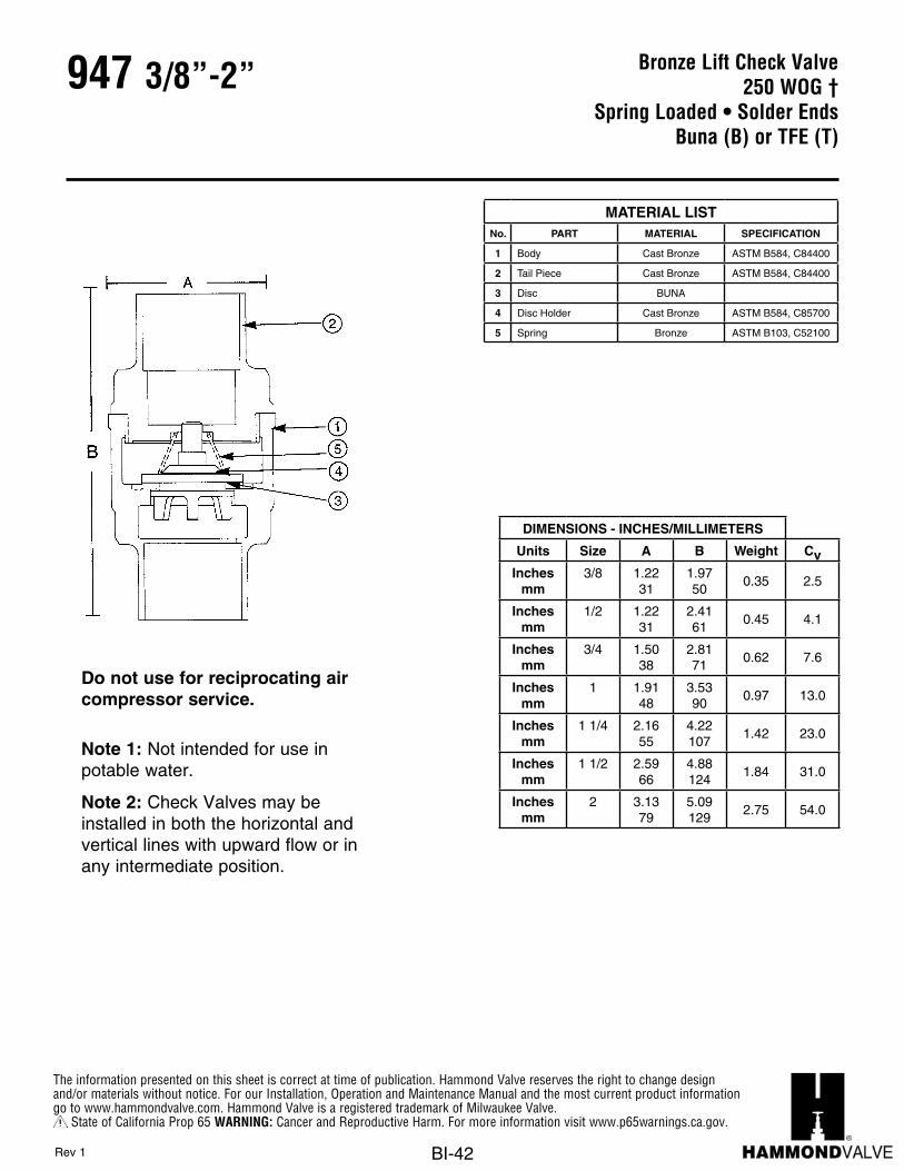
The information presented on this sheet is correct at time of publication. Hammond Valve reserves the right to change design and/or materials without notice. For our Installation, Operation and Maintenance Manual and the most current product information go to www.hammondvalve.com. Hammond Valve is a registered trademark of Milwaukee Valve.
State of California Prop 65 WARNING: Cancer and Reproductive Harm. For more information visit www.p65warnings.ca.gov.
BI-42
947 3/8”-2”
CHECK 1548T/1548BBRONZE SPRING CHECK VALVE
Units Size A B C WeightInches 3/8 1 7/32 2 5/32 1 31/32
MM 9.53 30.96 54.76 50.01Inches 1/2 1 7/32 2 13/32 2 3/32
MM 12.70 30.96 61.11 53.19Inches 3/4 1 1/2 3 13/16 2 5/16
MM 19.05 38.10 96.85 58.75Inches 1 1 29/32 3 17/32 2 21/32
MM 25.40 48.41 89.69 67.46Inches 1 1/4 2 5/32 4 7/8 3 3/32
MM 31.75 54.76 123.83 78.59Inches 1 1/2 2 19/32 4 7/32 3 5/16
MM 38.10 65.89 107.16 84.15Inches 2 3 1/8 5 3/32 3 25/32
MM 50.80 79.38 129.39 96.04
1.42
1.84
2.75
DIMENSIONS - INCHES / MILIMETERS
.45
.62
.97
www.milwaukeevalve.com
PART MATERIAL SPECIFICATION1 Body Cast Bronze ASTM B 584, C844002 Tail Piece Cast Bronze ASTM B 584, C844003 Disc TFE/BUNA*4 Disc Holder Cast Bronze ASTM B 584, C857005 Spring Bronze ASTM B 103, C52100
MATERIAL SPECIFICATIONNO.
05/05 Printed on recycled paper with soy ink. t i - 38
The information presented on this sheet is correct at the time of publication. Milwaukee Valve reserves the right to changedesign, and/or material specifications without notice. For the most current information access www.milwaukeevalve.com
• BRONZE BODY• SOLDERED ENDS• BRONZE SPRING• BUNA(B) or TEFLON(T) DISC RING• BRONZE DISC HOLDER
• 100% FACTORY TESTED• SILENT CLOSING
(minimizes water hammer)
FEATURES
RATING• 250 PSI NON-SHOCK COLD WATER, OIL OR GAS
Do not use for reciprocating air compressor service.
Note 1: Not intended for use in potable water.
Note 2: Check Valves may be installed in both the horizontal and vertical lines with upward flow or in any intermediate position.
Bronze Lift Check Valve250 WOG †
Spring Loaded • Solder EndsBuna (B) or TFE (T)
DIMENSIONS - INCHES/MILLIMETERS
Units Size A B Weight CvInches
mm3/8 1.22
311.9750
0.35 2.5
Inchesmm
1/2 1.2231
2.4161
0.45 4.1
Inchesmm
3/4 1.5038
2.8171
0.62 7.6
Inchesmm
1 1.9148
3.5390
0.97 13.0
Inchesmm
1 1/4 2.1655
4.22107
1.42 23.0
Inchesmm
1 1/2 2.5966
4.88124
1.84 31.0
Inchesmm
2 3.1379
5.09129
2.75 54.0
MATERIAL LISTNo. PART MATERIAL SPECIFICATION
1 Body Cast Bronze ASTM B584, C84400
2 Tail Piece Cast Bronze ASTM B584, C84400
3 Disc BUNA
4 Disc Holder Cast Bronze ASTM B584, C85700
5 Spring Bronze ASTM B103, C52100
Rev 1

The information presented on this sheet is correct at time of publication. Hammond Valve reserves the right to change design and/or materials without notice. For our Installation, Operation and Maintenance Manual and the most current product information go to www.hammondvalve.com. Hammond Valve is a registered trademark of Milwaukee Valve.
State of California Prop 65 WARNING: Cancer and Reproductive Harm. For more information visit www.p65warnings.ca.gov.
BI-43
Bronze Check Valve150 SWP - 300 WOG †
Horizontal Swing • Threaded EndsTFE Disc
Conforms to: MSS SP-80
IB946 1/4”-2”
Rev 7
Note: Not intended for use in potable water.
DIMENSIONS - INCHES/MILLIMETERS
Units Size A B CvInches
mm1/4 2.13
541.3234
3.3
Inchesmm
3/8 2.1354
1.3234
6.0
Inchesmm
1/2 2.3159
1.3234
10.0
Inchesmm
3/4 2.6367
1.6943
18.0
Inchesmm
1 3.2583
2.0051
31.0
Inchesmm
1 1/4 3.5691
2.1354
54.0
Inchesmm
1 1/2 4.00102
2.3860
76.0
Inchesmm
2 4.75121
2.8171
131.0
† Non-Shock
MATERIAL LISTNo. PART MATERIAL SPECIFICATION
1 Body Bronze ASTM B62
2 Cap Bronze ASTM B62
3 Lever Brass Commercial
4 Disc TFE
5 Disc Holder
BrassASTM B161/4” to 3/4”
BronzeASTM B62
1” to 2”
6 Pin St. Steel Commercial
7 Plug (not shown) Brass ASTM B16
8 Retaining Ring St. Steel Commercial
9 Disc Nut Brass ASTM B16

The information presented on this sheet is correct at time of publication. Hammond Valve reserves the right to change design and/or materials without notice. For our Installation, Operation and Maintenance Manual and the most current product information go to www.hammondvalve.com. Hammond Valve is a registered trademark of Milwaukee Valve.
State of California Prop 65 WARNING: Cancer and Reproductive Harm. For more information visit www.p65warnings.ca.gov.
BI-44
Bronze Check Valve150 SWP - 300 WOG †
Horizontal Swing • Solder EndsTFE Disc
Conforms to: MSS SP-80
IB945 1/2”-2”
Rev 8
Note: Not intended for use in potable water.
DIMENSIONS - INCHES/MILLIMETERS
Units Size A B C D CvInches
mm1/2 2.75
701.3234
0.5013
1.7544
10.0
Inchesmm
3/4 3.3184
1.6943
0.7519
1.8146
18.0
Inchesmm
1 4.00102
1.9750
0.9123
2.1855
31.0
Inchesmm
1 1/4 4.25108
2.1655
0.9725
2.3159
54.0
Inchesmm
1 1/2 4.94125
2.4161
1.0928
2.7670
76.0
Inchesmm
2 6.13156
2.8171
1.3434
3.4588
131.0
† Non-Shock
MATERIAL LISTNo. PART MATERIAL SPECIFICATION
1 Body Bronze ASTM B62
2 Cap Bronze ASTM B62
3 Lever Brass Commercial
4 Disc Teflon
5 Disc Holder
BrassASTM B161/2” to 3/4”
BronzeASTM B62
1” to 2”
6 Pin St. Steel Commercial
7 Plug (not shown) Brass ASTM B16
8 Retaining Ring St. Steel Commercial
9 Disc Nut Brass ASTM B16
9
3
8
6 7

The information presented on this sheet is correct at time of publication. Hammond Valve reserves the right to change design and/or materials without notice. For our Installation, Operation and Maintenance Manual and the most current product information go to www.hammondvalve.com. Hammond Valve is a registered trademark of Milwaukee Valve.
State of California Prop 65 WARNING: Cancer and Reproductive Harm. For more information visit www.p65warnings.ca.gov.
BI-45
Bronze Check Valve150 SWP - 300 WOG †
Horizontal Swing • Threaded EndsY-Pattern
Conforms to: MSS SP-80
515Y 1/4”-3”
Rev 5
Note: Not intended for use in potable water.
DIMENSIONS - INCHES/MILLIMETERS
Units Size A B CvInches
mm1/4 2.25
571.6341
2.3
Inchesmm
3/8 2.2557
1.6341
4.3
Inchesmm
1/2 2.6367
1.7545
7.2
Inchesmm
3/4 3.0076
1.9449
13.0
Inchesmm
1 3.6994
2.5064
22.0
Inchesmm
1 1/4 4.38111
3.0076
39.0
Inchesmm
1 1/2 4.63118
3.3184
56.0
Inchesmm
2 5.88149
4.00102
92.0
Inchesmm
2 1/2 7.00178
4.75121
150.0
Inchesmm
3 7.88200
5.57141
240.0
† Non-Shock
MATERIAL LISTNo. PART MATERIAL SPECIFICATION
1 Body Cast Bronze ASTM B62
2 CapBrass (1/4” - 3/8”)
Cast Bronze (1/2” and Larger)ASTM B16ASTM B62
3 DiscBronze (1/4” - 3/8”)Brass (1/2” - 1 1/2”)Cast Bronze (2”-3”)
ASTM B505ASTM B453ASTM B62
4 LeverSilicon Bronze (1/4” - 2”)Cast Bronze (2 1/2” - 3”)
ASTM B584ASTM B62
5 Pin St. Steel TYPE 303
6 Plug (not shown) Brass ASTM B16
7 Retaining Ring St. Steel TYPE 304

The information presented on this sheet is correct at time of publication. Hammond Valve reserves the right to change design and/or materials without notice. For our Installation, Operation and Maintenance Manual and the most current product information go to www.hammondvalve.com. Hammond Valve is a registered trademark of Milwaukee Valve.
State of California Prop 65 WARNING: Cancer and Reproductive Harm. For more information visit www.p65warnings.ca.gov.
BI-46
Bronze Check Valve200 SWP - 400 WOG †
Horizontal Swing • Threaded EndsY-Pattern
Conforms to: MSS SP-80
IB944 1/4”-3”
Note: Not intended for use in potable water.
MATERIAL LISTNo. PART MATERIAL SPECIFICATION
1 Body Cast Bronze ASTM B61
2 Cap Cast Bronze ASTM B61
3 Disc Cast Bronze ASTM B61
4 Lever Cast Bronze ASTM B61
5 Pin St. Steel Commercial
6 Plug (not shown) Rod Brass ASTM B16
7 Retaining Ring St. Steel ASTM A276 TY.304
Rev 10
DIMENSIONS - INCHES/MILLIMETERS
Units Size A B CvInches
mm1/4 2.25
571.6341
2.3
Inchesmm
3/8 2.2557
1.6341
4.3
Inchesmm
1/2 2.6367
1.7544
7.2
Inchesmm
3/4 3.0076
1.9449
13.0
Inchesmm
1 3.6994
2.5064
22.0
Inchesmm
1 1/4 4.38111
3.0076
39.0
Inchesmm
1 1/2 4.63118
3.3184
56.0
Inchesmm
2 5.88149
4.00102
92.0
Inchesmm
2 1/2 7.00178
4.75121
150.0
Inchesmm
3 7.88200
5.57141
240.0
† Non-Shock

The information presented on this sheet is correct at time of publication. Hammond Valve reserves the right to change design and/or materials without notice. For our Installation, Operation and Maintenance Manual and the most current product information go to www.hammondvalve.com. Hammond Valve is a registered trademark of Milwaukee Valve.
State of California Prop 65 WARNING: Cancer and Reproductive Harm. For more information visit www.p65warnings.ca.gov.
BI-47
Bronze Check Valve300 SWP - 600 WOG †
Horizontal Swing • Threaded EndsY-Pattern
Conforms to: MSS SP-80
IB949 1/4”-3”
Note: Not intended for use in potable water.
MATERIAL LISTNo. PART MATERIAL SPECIFICATION
1 Body Cast Bronze ASTM B61
2 Cap Cast Bronze ASTM B61
3 Disc Cast Bronze ASTM B61
4 Lever Cast Bronze ASTM B61
5 Pin St. Steel Commercial
6 Plug Rod Brass ASTM B16
7 Retaining Ring St. Steel ASTM A276 TY.304
Rev 11
DIMENSIONS - INCHES/MILLIMETERS
Units Size A B CvInches
mm1/4 2.25
571.6341
2.3
Inchesmm
3/8 2.2557
1.6341
4.3
Inchesmm
1/2 2.6367
1.7544
7.2
Inchesmm
3/4 3.0076
1.9449
13.0
Inchesmm
1 3.6994
2.5064
22.0
Inchesmm
1 1/4 4.38111
3.0076
39.0
Inchesmm
1 1/2 4.63118
3.3184
56.0
Inchesmm
2 5.88149
4.00102
92.0
Inchesmm
2 1/2 7.00178
4.75121
150.0
Inchesmm
3 7.88200
5.57141
240.0
† Non-Shock

The information presented on this sheet is correct at time of publication. Hammond Valve reserves the right to change design and/or materials without notice. For our Installation, Operation and Maintenance Manual and the most current product information go to www.hammondvalve.com. Hammond Valve is a registered trademark of Milwaukee Valve.
State of California Prop 65 WARNING: Cancer and Reproductive Harm. For more information visit www.p65warnings.ca.gov.
BI-48
Iron Gate Valve125 SWP - 200 WOG †
Non-Rising Stem • Solid Wedge DiscBolted Bonnet • Flanged Ends
Conforms to: MSS SP-70
IR1138 2”-12”
Flange shape and drilling to specification ASME B 16.1 (125 lb.) MATERIAL LISTNo. PART MATERIAL SPECIFICATION
1 Handwheel Nut Steel
2 Name Plate Aluminum
3 Handwheel Cast Iron ASTM A126, Class B
4 Stem Brass ASTM B16
5 Gland Follower Nut Bronze
6 Gland Follower Cast Iron ASTM A126, Class B
7 Gland Follower Bolt Steel
8 Packing Gland Brass ASTM B16
9 Stuffing Box Cast Iron ASTM A126, Class B
10 Packing Graphite
11 Stuffing Box Gasket Graphite
12 Bonnet Cast Iron ASTM A126, Class B
13 Body Bolt Steel
14 Body Gasket Graphite
15 Body Nut Steel
16 Wedge Bushing Cast Bronze ASTM B62
17 Seat Ring Cast Bronze ASTM B62
18 Wedge Face Ring Cast Bronze ASTM B62
19 Wedge Cast Iron ASTM A126, Class B
20 Body Cast Iron ASTM A126, Class B
21Stuffing Box Nut(not shown)
Bronze
1 Sizes through 4” have bronze wedges. Sizes 5” throught 12” made with cast iron wedge with bronze wedge face rings
Rev 10
DIMENSIONS - INCHES/MILLIMETERS
Units Size A B C D E CvInches
mm2 7.00
17812.00305
7.00178
6.00152
0.6316 215
Inchesmm
2 1/2 7.50191
13.25337
7.00178
7.00178
0.6917 335
Inchesmm
3 8.00203
13.50343
8.00203
7.50191
0.7519 510
Inchesmm
4 9.00229
17.00432
10.00254
9.00229
0.9424 945
Inchesmm
5 10.00254
18.00457
12.00305
10.00254
0.9424 1525
Inchesmm
6 10.50267
22.00559
12.00305
11.00279
1.0025 2250
Inchesmm
8 11.50292
26.50673
14.00356
13.50343
1.1329 4150
Inchesmm
10 13.00330
30.00762
16.00406
16.00406
1.1930 6700
Inchesmm
12 14.00356
35.00889
18.00457
19.00483
1.2532 9925
† Non-Shock

The information presented on this sheet is correct at time of publication. Hammond Valve reserves the right to change design and/or materials without notice. For our Installation, Operation and Maintenance Manual and the most current product information go to www.hammondvalve.com. Hammond Valve is a registered trademark of Milwaukee Valve.
State of California Prop 65 WARNING: Cancer and Reproductive Harm. For more information visit www.p65warnings.ca.gov.
BI-49
Iron Gate Valve125 SWP - 200 WOG †
Non-Rising Stem • Solid Wedge DiscBolted Bonnet • Flanged Ends
Conforms to: MSS SP-70
IR1138-HI 2”-12”
Flange shape and drilling to specification ASME B 16.1 (125 lb.) MATERIAL LISTNo. PART MATERIAL SPECIFICATION
1 Handwheel Nut Steel ASTM A307
2 Name Plate Aluminum
3 Handwheel Cast Iron ASTM A126, Class B
4 Stem Brass ASTM B16
5 Gland Follower Nut Steel ASTM A307
6 Gland Follower Ductile Iron ASTM A536
7 Gland Follower Bolt Steel ASTM A307
8 Packing Gland Cast Bronze ASTM B62
9 Stuffing Box Cast Iron ASTM A126, Class B
10 Packing Graphite
11 Stuffing Box Gasket Graphite
12 Bonnet Cast Iron ASTM A126, Class B
13 Body Bolt Steel ASTM A307
14 Body Gasket Graphite
15 Body Nut Steel ASTM A307
16 Wedge Bushing Bronze ASTM B62
17 Seat Ring Bronze ASTM B62
18 Wedge Face Ring Bronze ASTM B62
19 Wedge Cast Iron ASTM A126, Class B
20 Body Cast Iron ASTM A126, Class B
21Stuffing Box Nut(not shown)
Steel ASTM A307
Rev 9
DIMENSIONS - INCHES/MILLIMETERS
Units Size A B C D E CvInches
mm2 7.00
17812.00305
7.00178
6.00152
0.6316 215
Inchesmm
2 1/2 7.50191
13.25337
7.00178
7.00178
0.6917 335
Inchesmm
3 8.00203
13.50343
8.00203
7.50191
0.7519 510
Inchesmm
4 9.00229
17.00432
10.00254
9.00229
0.9424 945
Inchesmm
5 10.00254
18.00457
12.00305
10.00254
0.9424 1525
Inchesmm
6 10.50267
22.00559
12.00305
11.00279
1.0025 2250
Inchesmm
8 11.50292
26.50673
14.00356
13.50343
1.1329 4150
Inchesmm
10 13.00330
30.00762
16.00406
16.00406
1.1930 6700
Inchesmm
12 14.00356
35.00889
18.00457
19.00483
1.2532 9925
Suffix HI – Signifies International Valves.† Non-Shock

The information presented on this sheet is correct at time of publication. Hammond Valve reserves the right to change design and/or materials without notice. For our Installation, Operation and Maintenance Manual and the most current product information go to www.hammondvalve.com. Hammond Valve is a registered trademark of Milwaukee Valve.
State of California Prop 65 WARNING: Cancer and Reproductive Harm. For more information visit www.p65warnings.ca.gov.
BI-50
Iron Gate Valve125 SWP - 200 WOG †
Non-Rising Stem • Solid Wedge DiscBolted Bonnet • Flanged Ends
Conforms to: MSS SP-70
IR1144-HI 2”-12”
MATERIAL LISTNo. PART MATERIAL SPECIFICATION
1 Handwheel Nut Ductile Iron ASTM A536
2 Name Plate Aluminum
3 Handwheel Cast Iron ASTM A126, Class B
4 Stem Steel ASTM A108-Gr.1020
5 Gland Follower Nut Steel ASTM A307
6 Gland Follower Ductile Iron ASTM A536
7 Gland Follower Bolt Steel ASTM A307-B
8 Packing Gland Cast Iron ASTM A126, Class B
9 Stuffing Box Cast Iron ASTM A126, Class B
10 Packing Graphite Graphite
11 Stuffing Box Gasket Graphite Graphite
12 Bonnet Cast Iron ASTM A126, Class B
13 Body Nut Steel ASTM A307-A
14 Body Gasket Graphite Graphite
15 Body Nut Steel ASTM A563-B
16 Wedge Bushing Ductile Iron ASTM A536
17 Seat Ring Cast Iron ASTM A126, Class B
18 Wedge Cast Iron ASTM A126, Class B
19 Body Cast Iron ASTM A126, Class B
20Stuffing Box Nut(not shown)
Steel ASTM A563-B
DIMENSIONS - INCHES/MILLIMETERS
Units Size A B C D E CvInches
mm2 7.00
17812.00305
7.00178
6.00152
0.6316 215
Inchesmm
2 1/2 7.50191
13.25337
7.00178
7.00178
0.6917 335
Inchesmm
3 8.00203
13.50343
8.00203
7.50191
0.7519 510
Inchesmm
4 9.00229
17.00432
10.00254
9.00229
0.9424 945
Inchesmm
5 10.00254
18.00457
12.00305
10.00254
0.9424 1525
Inchesmm
6 10.50267
22.00559
12.00305
11.00279
1.0025 2250
Inchesmm
8 11.50292
26.50673
14.00356
13.50343
1.1329 4150
Inchesmm
10 13.00330
30.00762
16.00406
16.00406
1.1930 6700
Inchesmm
12 14.00356
35.00889
18.00457
19.00483
1.2532 9925
† Non-Shock
Flange shape and drilling to specification ASME B 16.1 (125 lb.)
Rev 10

The information presented on this sheet is correct at time of publication. Hammond Valve reserves the right to change design and/or materials without notice. For our Installation, Operation and Maintenance Manual and the most current product information go to www.hammondvalve.com. Hammond Valve is a registered trademark of Milwaukee Valve.
State of California Prop 65 WARNING: Cancer and Reproductive Harm. For more information visit www.p65warnings.ca.gov.
BI-51
Iron Gate Valve125 SWP - 200 WOG †
OS & Y • Solid Wedge DiscBolted Bonnet • Flanged Ends
Conforms to: MSS SP-70
IR1140 2”-12”
Flange shape and drilling to specification ASME B 16.1 (125 lb.) MATERIAL LISTNo. PART MATERIAL SPECIFICATION
1 Stem Brass ASTM B16
2 Handwheel Nut Ductile Iron
3 Name Plate Aluminum
4 Yoke Bushing Cast Bronze ASTM B62
5 Handwheel Cast Iron ASTM A126, Class B
6 2 Yoke Bushing Nut Cast Iron ASTM A126, Class B
7 1 Bonnet Cast Iron ASTM A126, Class B
8 1 Yoke Cast Iron ASTM A126, Class B
9 Gland Follower Nut Steel ASTM A307-B
10 Gland Follower Ductile Iron ASTM A536
11 Packing Gland Cast Bronze ASTM B62
12 Packing Graphite
13 Gland Follower Bolt Steel ASTM A307-B
14 Backseat Bushing Cast Bronze ASTM B62
15 Nut Steel ASTM A307-B
16 Body Gasket Graphite
17 Bolt Steel ASTM A307-B
18 Body Cast Iron ASTM A126, Class B
19 Wedge Cast Iron ASTM A126, Class B
20 Seat Ring Cast Bronze ASTM B62
21 Wedge Face Ring Cast Bronze ASTM B62
1 Sizes 2” to 3” made with yoke integral with bonnet. Sizes 4” through 12” made with separate yoke bolted to bonnet.
2 Sizes 2” to 3” only
Rev 11
DIMENSIONS - INCHES/MILLIMETERS
Units Size A B C D E CvInches
mm2 7.00
17812.00305
7.00178
6.00152
0.6316 215
Inchesmm
2 1/2 7.50191
16.88429
7.00178
7.00178
0.6917 335
Inchesmm
3 8.00203
18.75476
8.00203
7.50191
0.7519 510
Inchesmm
4 9.00229
17.00432
10.00254
9.00229
0.9424 945
Inchesmm
5 10.00254
18.00457
12.00305
10.00254
0.9424 1525
Inchesmm
6 10.50267
30.13765
12.00305
11.00279
1.0025 2250
Inchesmm
8 11.50292
40.131019
14.00356
13.50343
1.1329 4150
Inchesmm
10 13.00330
48.251226
16.00406
16.00406
1.8146 6700
Inchesmm
12 14.00356
56.881445
18.00457
19.00483
1.2532 9925
† Non-Shock

The information presented on this sheet is correct at time of publication. Hammond Valve reserves the right to change design and/or materials without notice. For our Installation, Operation and Maintenance Manual and the most current product information go to www.hammondvalve.com. Hammond Valve is a registered trademark of Milwaukee Valve.
State of California Prop 65 WARNING: Cancer and Reproductive Harm. For more information visit www.p65warnings.ca.gov.
BI-52
Iron Gate Valve125 SWP - 200 WOG †
OS & Y • Solid Wedge DiscBolted Bonnet • Flanged Ends
Conforms to: MSS SP-70
IR1140-HI 2”-12”
DIMENSIONS - INCHES/MILLIMETERS
Units Size A B C D E CvInches
mm2 7.00
17815.00381
7.00178
6.00152
0.6316 215
Inchesmm
2 1/2 7.50191
16.88429
7.00178
7.00178
0.6917 335
Inchesmm
3 8.00203
18.75476
8.00203
7.50191
0.7519 510
Inchesmm
4 9.00229
22.75578
10.00254
9.00229
0.9424 945
Inchesmm
5 10.00254
27.13689
12.00305
10.00254
0.9424 1525
Inchesmm
6 10.50267
30.13765
12.00305
11.00279
1.0025 2250
Inchesmm
8 11.50292
40.131019
14.00356
13.50343
1.1329 4150
Inchesmm
10 13.00330
48.251226
16.00406
16.00406
1.8146 6700
Inchesmm
12 14.00356
56.881445
18.00457
19.00483
1.2532 9925
Suffix HI – Signifies International Valves.† Non-Shock
Rev 3
MATERIAL LISTNo. PART MATERIAL SPECIFICATION
1 Stem Brass ASTM B16
2 Handwheel Nut Ductile Iron
3 Name Plate Aluminum
4 Yoke Bushing Cast Bronze ASTM B62
5 Handwheel Cast Iron ASTM A126, Class B
6 2 Yoke Bushing Nut Cast Iron ASTM A126, Class B
7 1 Bonnet Cast Iron ASTM A126, Class B
8 1 Yoke Cast Iron ASTM A126, Class B
9 Gland Follower Nut Steel ASTM A307-B
10 Gland Follower Ductile Iron ASTM A536
11 Packing Gland Cast Bronze ASTM B62
12 Packing Graphite
13 Gland Follower Bolt Steel ASTM A307-B
14 Backseat Bushing Cast Bronze ASTM B62
15 Nut Steel ASTM A307-B
16 Body Gasket Graphite
17 Bolt Steel ASTM A307-B
18 Body Cast Iron ASTM A126, Class B
19 Wedge Cast Iron ASTM A126, Class B
20 Seat Ring Cast Bronze ASTM B62
21 Wedge Face Ring Cast Bronze ASTM B62
1 Sizes 2” to 3” made with yoke integral with bonnet. Sizes 4” through 12” made with separate yoke bolted to bonnet.
2 Sizes 2” to 3” only

The information presented on this sheet is correct at time of publication. Hammond Valve reserves the right to change design and/or materials without notice. For our Installation, Operation and Maintenance Manual and the most current product information go to www.hammondvalve.com. Hammond Valve is a registered trademark of Milwaukee Valve.
State of California Prop 65 WARNING: Cancer and Reproductive Harm. For more information visit www.p65warnings.ca.gov.
BI-53
Iron Gate Valve100 SWP -150 WOG †
OS & Y • Solid Wedge DiscBolted Bonnet • Flanged Ends
Conforms to: MSS SP-70
IR1140-HI 14”-24”
Flange shape and drilling to specification ASME/ANSI B16.1 (125 lb.) MATERIAL LISTNo. PART MATERIAL SPECIFICATION
1 Stem Brass ASTM B16
2 Handwheel Nut Ductile Iron
3 Name Plate Aluminum
4 Yoke Bushing Cast Bronze ASTM B62
5 Handwheel Cast Iron ASTM A126, Class B
6 Yoke Bushing Nut Cast Iron ASTM A126, Class B
7 Bonnet Cast Iron ASTM A126, Class B
8 Yoke Cast Iron ASTM A126, Class B
9 Gland Follower Nut Steel ASTM A307-B
10 Gland Follower Ductile Iron ASTM A536
11 Packing Gland Cast Bronze ASTM B62
12 Packing Graphite
13 Gland Follower Bolt Steel ASTM A307-B
14 Backseat Bushing Cast Bronze ASTM B62
15 Nut Steel ASTM A307-B
16 Body Gasket Graphite
17 Bolt Steel ASTM A307-B
18 Body Cast Iron ASTM A126, Class B
19 Wedge Cast Iron ASTM A126, Class B
20 Seat Ring Cast Bronze ASTM B62
21 Wedge Face Ring Cast Bronze ASTM B62
Rev 9
DIMENSIONS - INCHES/MILLIMETERS
Units Size A B C D E CvInches
mm14.00 15.00
38162.001575
20.00508
21.00533
1.3835
13800
Inchesmm
16.00 16.00406
71.001803
22.00559
23.50570
1.4437
18375
Inchesmm
18.00 17.00432
75.001905
24.00610
25.00635
1.5640
23600
Inchesmm
20.00 18.00457
87.002210
24.00610
28.00699
1.6943
29600
Inchesmm
24.00 20.00508
100.002540
30.00762
32.00813
1.8848
43570
Suffix HI – Signifies International Valves.† Non-Shock

The information presented on this sheet is correct at time of publication. Hammond Valve reserves the right to change design and/or materials without notice. For our Installation, Operation and Maintenance Manual and the most current product information go to www.hammondvalve.com. Hammond Valve is a registered trademark of Milwaukee Valve.
State of California Prop 65 WARNING: Cancer and Reproductive Harm. For more information visit www.p65warnings.ca.gov.
BI-54
Iron Gate Valve125 SWP -200 WOG †
OS & Y • Solid Wedge DiscBolted Bonnet • Flanged Ends
Conforms to: MSS SP-70
IR1146-HI 2”-12”
Flange shape and drilling to specification ASME/ANSI B16.1 (125 lb.)
DIMENSIONS - INCHES/MILLIMETERS
Units Size A B C D E CvInches
mm2 7.00
17815.00381
7.00178
6.00152
0.6316 215
Inchesmm
2 1/2 1.50191
16.88429
7.00178
7.00178
0.6917 335
Inchesmm
3 8.00203
18.75476
8.00203
7.50191
0.7519 510
Inchesmm
4 9.00229
22.75578
10.00254
9.00229
0.9424 945
Inchesmm
5 10.00254
27.13689
12.00305
10.00254
0.9424 1525
Inchesmm
6 10.50267
30.13765
12.00305
11.00279
1.0025 2250
Inchesmm
8 11.50292
40.131019
14.00356
13.50343
1.1329 4150
Inchesmm
10 13.00330
48.251226
16.00406
16.00406
1.8146 6700
Inchesmm
12 14.00356
56.881445
18.00457
19.00483
1.2532 9925
Suffix HI – Signifies International Valves.† Non-Shock
MATERIAL LISTNo. PART MATERIAL SPECIFICATION
1 Stem Steel ASTM A108-Gr.1020
2 Handwheel Nut Ductile Iron ASTM A 536
3 Name Plate Aluminum
4 Yoke Bushing Ductile Iron ASTM A 536
5 Handwheel Cast Iron ASTM A126, Class B
6 2 Yoke Bushing Nut Cast Iron ASTM A 126, Class B
7 1 Bonnet Cast Iron ASTM A 126, Class B
8 1 Yoke Cast Iron ASTM A 126, Class B
9 Gland Follower Nut Steel ASTM A307-B
10 Gland Follower Ductile Iron ASTM A 536
11 Packing Gland Cast Iron ASTM A 126, Class B
12 Packing Graphite
13 Gland Follower Bolt Steel ASTM A307-B
14 Backseat Bushing Ductile Iron ASTM A 536
15 Nut Steel ASTM A307-B
16 Body Gasket Graphite
17 Bolt Steel ASTM A307-B
18 Body Cast Iron ASTM A126, Class B
19 Wedge Cast Iron ASTM A126, Class B
20 Seat Ring Cast Iron ASTM A126, Class B
1 Sizes 2” to 3” made with yoke integral with bonnet. Sizes 4” through 12” made with separate yoke bolted to bonnet.
2 Sizes 2” to 3” only
Rev 1
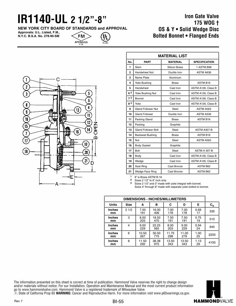
The information presented on this sheet is correct at time of publication. Hammond Valve reserves the right to change design and/or materials without notice. For our Installation, Operation and Maintenance Manual and the most current product information go to www.hammondvalve.com. Hammond Valve is a registered trademark of Milwaukee Valve.
State of California Prop 65 WARNING: Cancer and Reproductive Harm. For more information visit www.p65warnings.ca.gov.
BI-55
Iron Gate Valve175 WOG †
OS & Y • Solid Wedge DiscBolted Bonnet • Flanged Ends
IR1140-UL 2 1/2”-8”NEW YORK CITY BOARD OF STANDARDS and APPROVALApprovals: U.L. Listed, F.M.,N.Y.C. B.S.A. No. 278-90-SM
Units Size A B CInches 1 2 1/2 6 1/2 8
MM 25.40 63.50 165.10 203.20Inches 1 1/4 2 3/4 7 5/8 9 1/2
MM 31.75 69.85 193.68 241.30Inches 1 1/2 6 8 10
MM 38.10 152.40 203.20 254.00Inches 2 3 9 11 1/4
MM 50.80 76.20 228.60 285.75
DIMENSIONS - INCHES / MILIMETERS
PART MATERIAL SPECIFICATION1 Stem Brass2 Yoke Bushing Brass3 Handwheel Ductile Iron4 Bonnet Brass5 Packing Gland Brass6 Packing
7 Gland Follower Bolt
8 Body Brass9 Wedge Brass
CDA-844
MATERIAL LIST
Stainless Steel
CDA-360
CDA-844
NO.
† Non-Shock
i - 11
118-FPBRASS GATE
175 WP • O. S. AND Y. • Solid Wedge DiscScrewed Bonnet • Gland Packed • Screwed Ends
www.hammondvalve.com
t Printed on recycled paper with soy ink. 05/05
The information presented on this sheet is correct at the time of publication. Hammond Valve reserves the right to changedesign, and/or material specifications without notice. For the most current information access www.hammondvalve.com
NEW YORK CITY BOARD OF STANDARDS andAPPROVALApprovals: U.L. Listed, F.M.,N.Y.C. B.S.A. No. 1079-81-SA
MEA255-93-E
BETTER AT EVERY TURN
MATERIAL LISTNo. PART MATERIAL SPECIFICATION
1 Stem Silicon Brass 1 ASTM B98
2 Handwheel Nut Ductile Iron ASTM A636
3 Name Plate Aluminum
4 Yoke Bushing Brass ASTM B16
5 Handwheel Cast Iron ASTM A126, Class B
6 2 Yoke Bushing Nut Cast Iron ASTM A126, Class B
7 3 Bonnet Cast Iron ASTM A126, Class B
8 3 Yoke Cast Iron ASTM A126, Class B
9 Gland Follower Nut Steel ASTM A563
10 Gland Follower Ductile Iron ASTM A536
11 Packing Gland Brass ASTM B16
12 Packing Graphite
13 Gland Follower Bolt Steel ASTM A307-B
14 Backseat Bushing Brass ASTM B16
15 Nut Steel ASTM A563
16 Body Gasket Graphite
17 Bolt Steel ASTM A 307-B
18 Body Cast Iron ASTM A126, Class B
19 Wedge Cast Iron ASTM A126, Class B
20 Seat Ring Cast Bronze ASTM B62
21 Wedge Face Ring Cast Bronze ASTM B62
1 8” is Brass ASTM B-16 2 Sizes 2 1/2” to 6” inch only. 3 Sizes 2 1/2” and 3” made with yoke integral with bonnet.
Sizes 4” through 8” made with separate yoke bolted to bonnet.
Rev 7
DIMENSIONS - INCHES/MILLIMETERS
Units Size A B C D E CvInches
mm2 1/2 7.50
19116.00406
7.00178
7.00178
0.6917 335
Inchesmm
3 8.00203
18.50470
7.50191
7.50191
0.7519 510
Inchesmm
4 9.00229
22.25565
8.00203
9.00229
0.9424 945
Inchesmm
6 10.50267
30.50775
11.75298
11.00279
1.0025 2250
Inchesmm
8 11.50292
38.38975
13.50343
13.50343
1.1329 4150

The information presented on this sheet is correct at time of publication. Hammond Valve reserves the right to change design and/or materials without notice. For our Installation, Operation and Maintenance Manual and the most current product information go to www.hammondvalve.com. Hammond Valve is a registered trademark of Milwaukee Valve.
State of California Prop 65 WARNING: Cancer and Reproductive Harm. For more information visit www.p65warnings.ca.gov.
BI-56
Iron Gate Valve250 SWP - 500 WOG †
OS & Y • Solid Wedge DiscBolted Bonnet • Flanged Ends
Conforms to: MSS SP-70
IR330 2”-12”
Flange shape and drilling to specification ASME B 16.1 (250 lb.) MATERIAL LISTNo. PART MATERIAL SPECIFICATION
1 Stem Brass ASTM B16
2 Handwheel Nut Ductile Iron
3 Name Plate Aluminum
4 Yoke Bushing Cast Bronze ASTM B62
5 Handwheel Cast Iron ASTM A126, Class B
6 2 Yoke Bushing Nut Cast Iron ASTM A126, Class B
7 1 Bonnet Cast Iron ASTM A126, Class B
8 1 Yoke Cast Iron ASTM A126, Class B
9 Gland Follower Nut Steel ASTM A307-B
10 Gland Follower Ductile Iron ASTM A 536
11 Packing Gland Cast Bronze ASTM B62
12 Packing Graphite
13 Gland Follower Bolt Steel ASTM A307-B
14 Backseat Bushing Cast Bronze ASTM B62
15 Nut Steel ASTM A307-B
16 Body Gasket Graphite
17 Bolt Steel ASTM A307-B
18 Body Cast Iron ASTM A126, Class B
19 Wedge Cast Iron ASTM A126, Class B
20 Seat Ring Cast Bronze ASTM B62
21 Wedge Face Ring Cast Bronze ASTM B62
1 Sizes 2” to 3” made with yoke integral with bonnet. 2 Sizes 4” through 12” made with separate yoke bolted to bonnet.
Rev 8
DIMENSIONS - INCHES/MILLIMETERS
Units Size A B C D E CvInches
mm2 8.50
21616.00406
8.00203
6.50165
0.8822 215
Inchesmm
2 1/2 9.50241
16.88429
8.00203
7.50191
1.0025 335
Inchesmm
3 11.13283
19.38492
10.00254
8.25210
1.1329 510
Inchesmm
4 12.00305
23.63600
12.00305
10.00254
1.2532 945
Inchesmm
5 15.00381
27.75705
12.00305
11.00279
1.3835 1525
Inchesmm
6 15.88403
32.38822
14.00356
12.50318
1.4437 2250
Inchesmm
8 16.50419
40.501245
16.00406
15.00381
1.6341 4150
Inchesmm
10 18.00457
49.001245
18.00457
17.50445
1.8848 6700
Inchesmm
12 19.75502
56.881445
20.00508
20.50521
2.0051 9925
† Non-Shock

The information presented on this sheet is correct at time of publication. Hammond Valve reserves the right to change design and/or materials without notice. For our Installation, Operation and Maintenance Manual and the most current product information go to www.hammondvalve.com. Hammond Valve is a registered trademark of Milwaukee Valve.
State of California Prop 65 WARNING: Cancer and Reproductive Harm. For more information visit www.p65warnings.ca.gov.
BI-57
Iron Gate Valve250 SWP - 500 WOG †
OS & Y • Solid Wedge DiscBolted Bonnet • Flanged Ends
Conforms to: MSS SP-70
IR330-HI 2”-12”
Flange shape and drilling to specification ASME B 16.1 (250 lb.) MATERIAL LISTNo. PART MATERIAL SPECIFICATION
1 Stem Brass ASTM B16
2 Handwheel Nut Ductile Iron
3 Name Plate Aluminum
4 Yoke Bushing Cast Bronze ASTM B62
5 Handwheel Cast Iron ASTM A126, Class B
6 2 Yoke Bushing Nut Cast Iron ASTM A126, Class B
7 1 Bonnet Cast Iron ASTM A126, Class B
8 1 Yoke Cast Iron ASTM A126, Class B
9 Gland Follower Nut Steel ASTM A307-B
10 Gland Follower Ductile Iron ASTM A536
11 Packing Gland Cast Bronze ASTM B62
12 Packing Graphite
13 Gland Follower Bolt Steel ASTM A307-B
14 Backseat Bushing Cast Bronze ASTM B62
15 Nut Steel ASTM A307-B
16 Body Gasket Graphite
17 Bolt Steel ASTM A307-B
18 Body Cast Iron ASTM A126, Class B
19 Wedge Cast Iron ASTM A126, Class B
20 Seat Ring Cast Bronze ASTM B62
21 Wedge Face Ring Cast Bronze ASTM B62
1 Sizes 2” to 3” made with yoke integral with bonnet. 2 Sizes 4” through 12” made with separate yoke bolted to bonnet.
Rev 8
DIMENSIONS - INCHES/MILLIMETERS
Units Size A B C D E CvInches
mm2 8.50
21616.00406
8.00203
6.50165
0.8822 215
Inchesmm
2 1/2 9.50241
16.88429
8.00203
7.50191
1.0025 335
Inchesmm
3 11.13283
19.38492
10.00254
8.25210
1.1329 510
Inchesmm
4 12.00305
23.63600
12.00305
10.00254
1.2532 945
Inchesmm
5 15.00381
27.75705
12.00305
11.00279
1.3835 1525
Inchesmm
6 15.88403
32.38822
14.00356
12.50318
1.4437 2250
Inchesmm
8 16.50419
40.501245
16.00406
15.00381
1.6341 4150
Inchesmm
10 18.00457
49.001245
18.00457
17.50445
1.8848 6700
Inchesmm
12 19.75502
56.881445
20.00508
20.50521
2.0051 9925
Suffix HI – Signifies International Valves.† Non-Shock

The information presented on this sheet is correct at time of publication. Hammond Valve reserves the right to change design and/or materials without notice. For our Installation, Operation and Maintenance Manual and the most current product information go to www.hammondvalve.com. Hammond Valve is a registered trademark of Milwaukee Valve.
State of California Prop 65 WARNING: Cancer and Reproductive Harm. For more information visit www.p65warnings.ca.gov.
BI-58
Iron Globe Valve125 SWP - 200 WOG †
Solid Wedge DiscBolted Bonnet • Flanged Ends
Conforms to: MSS SP-85
IR116 2”-10”
Flange shape and drilling to specification ASME B16.1 (125 lb.)MATERIAL LIST
No. PART MATERIAL SPECIFICATION
1 Handwheel Nut Steel ASTM A307-B
2 Name Plate Aluminum
3 Handwheel Cast Iron ASTM A126, Class B
4 Yoke Bushing Bronze ASTM B62
5 Bonnet Cast Iron ASTM A 126, Class B
6 Stem Brass ASTM B16
7 Gland Follower Nut Bronze
8 Gland Follower Stud Steel ASTM A307-B
9 Gland Follower Ductile Iron ASTM A536
10 Packing Gland Cast Bronze ASTM B62
11 Packing Graphite
12 Body Bolt Steel ASTM A307-B
13 Body Gasket Graphite
14 Body Nut Steel ASTM A307-B
15 Swivel Nut Bronze ASTM B62
16 1 Disc Bronze ASTM B62
17 Seat Ring Bronze ASTM B62
18 Body Cast Iron ASTM A 126, Class B
19 1 Taper Pin Steel
20 1 Guide Pin Brass ASTM B16
1 Sizes through 4” have bronze ASTM B62 disc. 5” through 12” have iron disc with bronze disc face rings and brass pilots.
Rev 8
DIMENSIONS - INCHES/MILLIMETERS
Units Size A B C D E CvInches
mm2 8.00
2.0310.19259
7.00178
6.00152
0.6316 45
Inchesmm
2 1/2 8.50216
11.81300
7.00178
7.00178
0.6917 70
Inchesmm
3 9.50241
12.50318
8.00203
7.50191
0.7519 105
Inchesmm
4 11.50292
15.81402
10.00254
9.00229
0.9424 195
Inchesmm
5 13.00331
16.50419
12.00305
10.00254
0.9424 315
Inchesmm
6 14.00356
18.88479
12.00305
11.00279
1.0025 465
Inchesmm
8 19.50495
21.13537
14.00356
13.50343
1.1329 860
Inchesmm
10 24.50622
25.19640
16.00406
16.00406
1.1930 1390
† Non-Shock Note: Does not meet Senate Law S.3874

The information presented on this sheet is correct at time of publication. Hammond Valve reserves the right to change design and/or materials without notice. For our Installation, Operation and Maintenance Manual and the most current product information go to www.hammondvalve.com. Hammond Valve is a registered trademark of Milwaukee Valve.
State of California Prop 65 WARNING: Cancer and Reproductive Harm. For more information visit www.p65warnings.ca.gov.
BI-59
Iron Globe Valve125 SWP - 200 WOG †
Solid Wedge DiscBolted Bonnet • Flanged Ends
Conforms to: MSS SP-85
IR116-HI 2”-10”
Flange shape and drilling to specification ASME B16.1 (125 lb.) MATERIAL LISTNo. PART MATERIAL SPECIFICATION
1 Handwheel Nut Steel ASTM A307-B
2 Name Plate Aluminum
3 Handwheel Cast Iron ASTM A126, Class B
4 Yoke Bushing Bronze ASTM B62
5 Bonnet Cast Iron ASTM A126, Class B
6 Stem Brass ASTM B16
7 Gland Follower Nut Bronze
8 Gland Follower Stud Steel ASTM A307-B
9 Gland Follower Ductile Iron ASTM A 536
10 Packing Gland Cast Bronze ASTM B62
11 Packing Graphite
12 Body Bolt Steel ASTM A307-B
13 Body Gasket Graphite
14 Body Nut Steel ASTM A307-B
15 Swivel Nut Bronze ASTM B62
16 1 Disc Bronze ASTM B62
17 Seat Ring Bronze ASTM B62
18 Body Cast Iron ASTM A126, Class B
19 1 Taper Pin Steel
20 1 Guide Pin Brass ASTM B16
1 Sizes through 4” have bronze ASTM B62 disc. 5” through 12” have iron disc with bronze disc face rings and brass pilots.
Rev 9
DIMENSIONS - INCHES/MILLIMETERS
Units Size A B C D E CvInches
mm2 8.00
2.0310.19259
7.00178
6.00152
0.6316 45
Inchesmm
2 1/2 8.50216
11.81300
7.00178
7.00178
0.6917 70
Inchesmm
3 9.50241
12.50318
8.00203
7.50191
0.7519 105
Inchesmm
4 11.50292
15.81402
10.00254
9.00229
0.9424 195
Inchesmm
5 13.00331
16.50419
12.00305
10.00254
0.9424 315
Inchesmm
6 14.00356
18.88479
12.00305
11.00279
1.0025 465
Inchesmm
8 19.50495
21.13537
14.00356
13.50343
1.1329 860
Inchesmm
10 24.50622
25.19640
16.00406
16.00406
1.1930 1390
Suffix HI – Signifies International Valves.† Non-ShockNote: Does not meet Senate Law S.3874

The information presented on this sheet is correct at time of publication. Hammond Valve reserves the right to change design and/or materials without notice. For our Installation, Operation and Maintenance Manual and the most current product information go to www.hammondvalve.com. Hammond Valve is a registered trademark of Milwaukee Valve.
State of California Prop 65 WARNING: Cancer and Reproductive Harm. For more information visit www.p65warnings.ca.gov.
BI-60
GLOBE F-2983-MIRON
250 lb. SWP-500 lb. WOG† • Solid Disc • Bolted BonnetGland Packed • Flanged Ends
Units Size A B C D E Inches 2 1/2 11 1/2 13 9/16 8 7 1/2 1
MM 63.50 292.10 344.50 203.20 190.50 25.40Inches 3 12 1/2 13 7/8 10 8 1/4 1 1/8
MM 76.20 317.50 352.43 254.00 209.55 28.58Inches 4 14 16 5/8 11 10 1 1/4
MM 101.60 355.60 422.28 279.40 254.00 31.75Inches 5 15 3/4 20 7/8 12 11 1 3/8
MM 127.00 400.05 530.23 304.80 279.40 34.93Inches 6 17 1/2 26 1/4 16 12 1/2 1 7/16
MM 152.40 444.50 666.75 406.40 317.50 36.53Inches 8 21 30 1/8 16 15 1 5/8
MM 203.20 533.40 765.18 406.40 381.00 41.28
DIMENSIONS - INCHES / MILIMETERS
F-2983-M Conforms to: MSS SP-85.
DESCRIPTION MATERIAL & SPECIFICATION1 Handwheel Nut Steel2 Identification Plate Aluminum3 Handwheel Cast Iron ASTM A 126, Class B4 Stem Brass ASTM B 165 Yoke Bushing Cast Bronze ASTM B 626 Bonnet Cast Iron ASTM A 126, Class B7 Gland Follower Nut Bronze8 Gland Follower Stud Steel9 Gland Follower Cast Iron ASTM A 126, Class B
10 Packing Gland Brass ASTM B 1611 Hex Head Cap Screws Steel12 Packing Graphite13 Body Gasket Graphite14 Swivel Nut or Sleeve Cast Bronze ASTM B 6215 1 B ssalC ,621 A MTSA norI tsaCcsiD16 Disc Ring Cast Bronze ASTM B 6217 Disc Pilot Cast Bronze ASTM B 6218 Seat Ring Cast Bronze ASTM B 6219 Body Cast Iron ASTM A 126, Class B
1
NO.MATERIAL LIST
SPECIFICATIONS
Sizes through 4" have all bronze discs. Sizes 5" through 8" havecast iron disc with bronze disc face rings.
† Non-Shock
Flange shape and drilling to specification ASME B16.1 (250 lb.)
Iron Globe Valve250 SWP - 500 WOG †
Solid Wedge DiscBolted Bonnet • Flanged Ends
Conforms to: MSS SP-85
IR313 2 1/2”-6”
Flange shape and drilling to specification ASME B16.1 (250 lb.) MATERIAL LISTNo. PART MATERIAL SPECIFICATION
1 Handwheel Nut Steel
2 Name Plate Aluminum
3 Handwheel Cast Iron ASTM A126, Class B
4 Stem Brass ASTM B16
5 Yoke Bushing Cast Bronze ASTM B62
6 Bonnet Cast Iron ASTM A126, Class B
7 Gland Follower Nut Bronze
8 Gland Follower Stud Steel
9 Gland Follower Cast Iron ASTM A126, Class B
10 Packing Gland Brass ASTM B16
11 Hex Head Cap Screws Steel
12 Packing Graphite
13 Body Gasket Graphite
14 Swivel Nut or Sleeve Cast Bronze ASTM B62
15 1 Disc Cast Iron ASTM A126, Class B
16 Disc Ring Cast Bronze ASTM B62
17 Disc Pilot Cast Bronze ASTM B62
18 Seat Ring Cast Bronze ASTM B62
19 Body Cast Iron ASTM A126, Class B
1 Sizes through 4” have all bronze discs. Sizes 5” through 8” have cast iron disc with bronze disc face rings.
Rev 8
DIMENSIONS - INCHES/MILLIMETERS
Units Size A B C D E CvInches
mm2 1/2 11.50
29213.56345
8.0020 7.50 1.00 70
Inchesmm
3 12.50318
13.88352
10.00254
8.25210
1.1329 105
Inchesmm
4 14.00356
16.63422
12.00305
10.00254
1.2532 195
Inchesmm
6 17.50445
26.25667
12.00305
12.50318
1.4437 465
† Non-Shock Note: Does not meet Senate Law S.3874

The information presented on this sheet is correct at time of publication. Hammond Valve reserves the right to change design and/or materials without notice. For our Installation, Operation and Maintenance Manual and the most current product information go to www.hammondvalve.com. Hammond Valve is a registered trademark of Milwaukee Valve.
State of California Prop 65 WARNING: Cancer and Reproductive Harm. For more information visit www.p65warnings.ca.gov.
BI-61
Iron Check Valve125 SWP - 200 WOG †
Horizontal Swing • Flanged EndsBolted Cover
Conforms to: MSS SP-71
IR1124 2”-12”
Flange shape and drilling to specification ASME B 16.1 (125 lb). MATERIAL LISTNo. PART MATERIAL SPECIFICATION
1 Bolt Steel
2 Name Plate Aluminum
3 Cover Cast Iron ASTM A126, Class B
4 Cover Gasket Graphite
5 Nut Steel
6 Side Plug Brass ASTM B16
7 Gasket Graphite
8 Hanger Pin SS 304 ASTM B16
9 Hanger Ductile Iron ASTM A536
10 1 Disc Cast Iron ASTM A126, Class B
11 Washer Steel
12 Cotton Pin Carbon Steel Galvonized
13 Seat Ring Bronze ASTM B 62
14 Disc Nut Steel ASTM A307
15 Body Cast Iron ASTM A126, Class B
16 Stud Bolt Brass ASTM B16
1 Valve Disc-Cast iron with bronze disc face rings.
Note 1: On pump discharge, the preferred check valve is either an in-line spring loaded valve or a swing design with lever and weight. Install these valves as far as possible from the pump and elbows with a minimum distance of 5 times the pipe diameter.
Note 2: These iron body check valves may be installed in horizontal and vertical lines with upward flow or in intermediate position.
DIMENSIONS - INCHES/MILLIMETERS
Units Size A B C D CvInches
mm2 8.00
2033.94100
6.001.52
0.6316 137
Inchesmm
2 1/2 8.50216
4.50114
7.00178
0.6917 221
Inchesmm
3 9.50241
5.13130
7.50191
0.7519 327
Inchesmm
4 11.50292
6.13156
9.00229
0.9424 605
Inchesmm
5 13.00330
6.81173
10.00254
0.9424 975
Inchesmm
6 14.00356
8.00203
11.00279
1.0025 1440
Inchesmm
8 19.50495
9.44240
13.50343
1.1329 2670
Inchesmm
10 24.50622
12.06306
16.00406
1.1930 4300
Inchesmm
12 27.50699
16.13410
19.00483 1.25 6350
† Non-Shock Note: Does not meet Senate Law S.3874
Rev 9

The information presented on this sheet is correct at time of publication. Hammond Valve reserves the right to change design and/or materials without notice. For our Installation, Operation and Maintenance Manual and the most current product information go to www.hammondvalve.com. Hammond Valve is a registered trademark of Milwaukee Valve.
State of California Prop 65 WARNING: Cancer and Reproductive Harm. For more information visit www.p65warnings.ca.gov.
BI-62
Iron Check Valve125 SWP - 200 WOG †
Horizontal Swing • Flanged EndsBolted Cover
Conforms to: MSS SP-71
Flange shape and drilling to specification ASME B 16.1 (125 lb).
IR1124-HI 2”-12”
MATERIAL LISTNo. PART MATERIAL SPECIFICATION
1 Bolt Steel
2 Name Plate Aluminum
3 Cover Cast Iron ASTM A126, Class B
4 Cover Gasket Graphite
5 Nut Steel
6 Side Plug Brass ASTM B16
7 Gasket Graphite
8 Hanger Pin SS 304 ASTM B16
9 Hanger Ductile Iron ASTM A536
10 1 Disc Cast Iron ASTM A126, Class B
11 Washer Steel
12 Cotton Pin Zinc Plated Steel
13 Seat Ring Bronze ASTM B62
14 Disc Nut Steel ASTM A307
15 Body Cast Iron ASTM A126, Class B
16 Stud Bolt Brass ASTM B16
1 Valve Disc-Cast iron with bronze disc face rings.
Note 1: On pump discharge, the preferred check valve is either an in-line spring loaded valve or a swing design with lever and weight. Install these valves as far as possible from the pump and elbows with a minimum distance of 5 times the pipe diameter.
Note 2: These iron body check valves may be installed in horizontal and vertical lines with upward flow or in intermediate position.
DIMENSIONS - INCHES/MILLIMETERS
Units Size A B C D CvInches
mm2 8.00
2034.56116
6.001.52
0.6316 137
Inchesmm
2 1/2 8.50216
5.38137
7.00178
0.6917 221
Inchesmm
3 9.50241
5.56141
7.50191
0.7519 327
Inchesmm
4 11.50292
6.69170
9.00229
0.9424 605
Inchesmm
5 13.00330
7.75197
10.00254
0.9424 975
Inchesmm
6 14.00356
9.50241
11.00279
1.0025 1440
Inchesmm
8 19.50495
10.38264
13.50343
1.1329 2670
Inchesmm
10 24.50622
12.00305
16.00406
1.1930 4300
Inchesmm
12 27.50699
13.50343
19.00483 1.25 6350
Suffix HI – Signifies International Valves.† Non-Shock
Rev 2
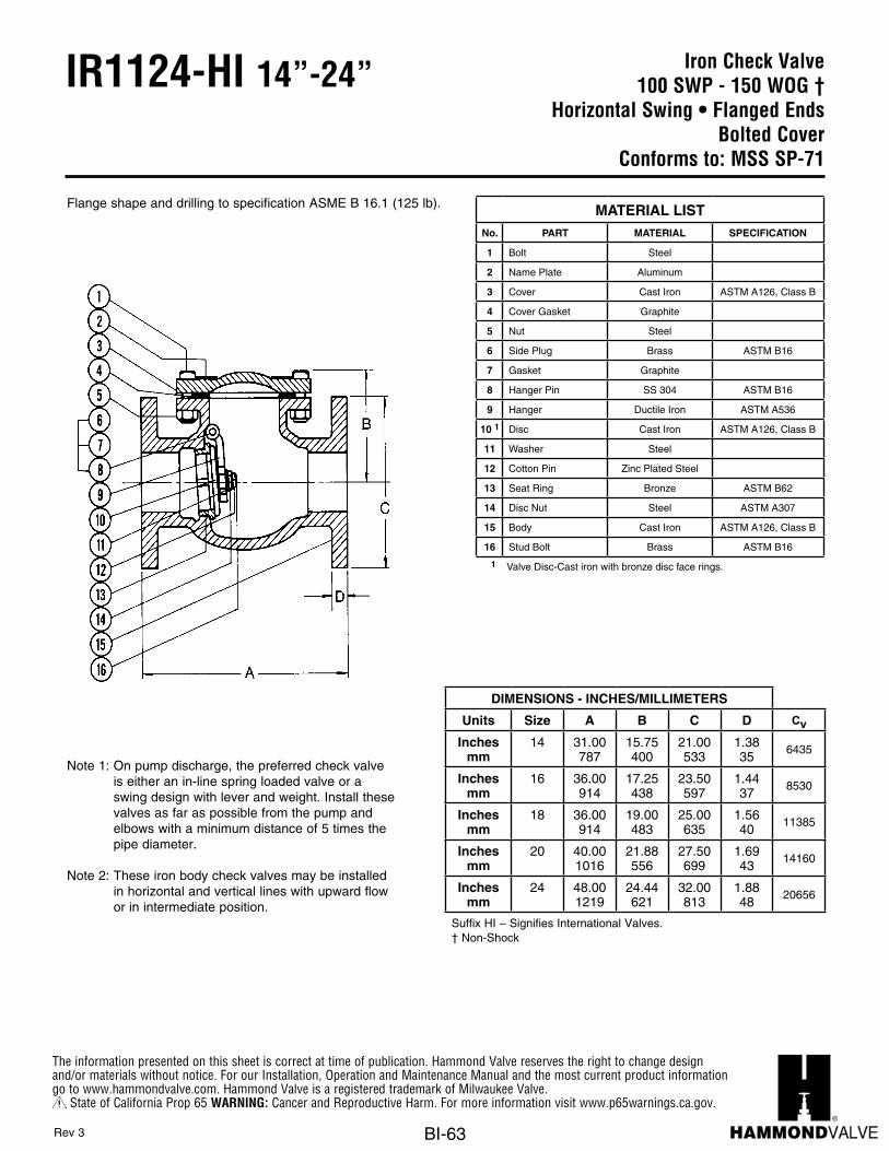
The information presented on this sheet is correct at time of publication. Hammond Valve reserves the right to change design and/or materials without notice. For our Installation, Operation and Maintenance Manual and the most current product information go to www.hammondvalve.com. Hammond Valve is a registered trademark of Milwaukee Valve.
State of California Prop 65 WARNING: Cancer and Reproductive Harm. For more information visit www.p65warnings.ca.gov.
BI-63
Iron Check Valve100 SWP - 150 WOG †
Horizontal Swing • Flanged EndsBolted Cover
Conforms to: MSS SP-71
IR1124-HI 14”-24”
Flange shape and drilling to specification ASME B 16.1 (125 lb).
Note 1: On pump discharge, the preferred check valve is either an in-line spring loaded valve or a swing design with lever and weight. Install these valves as far as possible from the pump and elbows with a minimum distance of 5 times the pipe diameter.
Note 2: These iron body check valves may be installed in horizontal and vertical lines with upward flow or in intermediate position.
MATERIAL LISTNo. PART MATERIAL SPECIFICATION
1 Bolt Steel
2 Name Plate Aluminum
3 Cover Cast Iron ASTM A126, Class B
4 Cover Gasket Graphite
5 Nut Steel
6 Side Plug Brass ASTM B16
7 Gasket Graphite
8 Hanger Pin SS 304 ASTM B16
9 Hanger Ductile Iron ASTM A536
10 1 Disc Cast Iron ASTM A126, Class B
11 Washer Steel
12 Cotton Pin Zinc Plated Steel
13 Seat Ring Bronze ASTM B62
14 Disc Nut Steel ASTM A307
15 Body Cast Iron ASTM A126, Class B
16 Stud Bolt Brass ASTM B16
1 Valve Disc-Cast iron with bronze disc face rings.
DIMENSIONS - INCHES/MILLIMETERS
Units Size A B C D Cv
Inchesmm
14 31.00787
15.75400
21.00533
1.3835
6435
Inchesmm
16 36.00914
17.25438
23.50597
1.4437
8530
Inchesmm
18 36.00914
19.00483
25.00635
1.5640
11385
Inchesmm
20 40.001016
21.88556
27.50699
1.6943
14160
Inchesmm
24 48.001219
24.44621
32.00813
1.8848
20656
Suffix HI – Signifies International Valves.† Non-Shock
Rev 3

The information presented on this sheet is correct at time of publication. Hammond Valve reserves the right to change design and/or materials without notice. For our Installation, Operation and Maintenance Manual and the most current product information go to www.hammondvalve.com. Hammond Valve is a registered trademark of Milwaukee Valve.
State of California Prop 65 WARNING: Cancer and Reproductive Harm. For more information visit www.p65warnings.ca.gov.
BI-64
Iron Check Valve125 SWP - 200 WOG †
Horizontal Swing • Flanged EndsBolted Cover
Conforms to: MSS SP-71
IR1126-HI 2”-12”
Flange shape and drilling to specification ASME B 16.1 (125 lb).
Note 1: On pump discharge, the preferred check valve is either an in-line spring loaded valve or a swing design with lever and weight. Install these valves as far as possible from the pump and elbows with a minimum distance of 5 times the pipe diameter.
Note 2: These iron body check valves may be installed in horizontal and vertical lines with upward flow or in intermediate position.
MATERIAL LISTNo. PART MATERIAL SPECIFICATION
1 Bolt Steel
2 Name Plate Aluminum
3 Cover Cast Iron ASTM A126, Class B
4 Cover Gasket Graphite
5 Nut Steel
6 Side Plug Steel
7 Gasket Graphite
8 Hanger Pin SS 304
9 Hanger Ductile Iron ASTM A536
10 Disc Cast Iron ASTM A126, Class B
11 Washer Steel
12 Cotton Pin Zinc Plated Steel
13 Seat Ring Bronze ASTM B62
14 Disc Nut Steel ASTM A307
15 Body Cast Iron ASTM A126, Class B
16 Stud Bolt Brass ASTM B16
DIMENSIONS - INCHES/MILLIMETERS
Units Size A B C D CvInches
mm2 8.00
2034.56116
6.001.52
0.6316 137
Inchesmm
2 1/2 8.50216
5.38137
7.00178
0.6917 221
Inchesmm
3 9.50241
5.56141
7.50191
0.7519 327
Inchesmm
4 11.50292
6.69170
9.00229
0.9424 605
Inchesmm
5 13.00330
7.75197
10.00254
0.9424 975
Inchesmm
6 14.00356
9.50241
11.00279
1.0025 1440
Inchesmm
8 19.50495
10.38264
13.50343
1.1329 2670
Inchesmm
10 24.50622
12.00305
16.00406
1.1930 4300
Inchesmm
12 27.50699
13.50343
19.00483
1.2532 6350
Suffix HI – Signifies International Valves.† Non-Shock
Rev 2

The information presented on this sheet is correct at time of publication. Hammond Valve reserves the right to change design and/or materials without notice. For our Installation, Operation and Maintenance Manual and the most current product information go to www.hammondvalve.com. Hammond Valve is a registered trademark of Milwaukee Valve.
State of California Prop 65 WARNING: Cancer and Reproductive Harm. For more information visit www.p65warnings.ca.gov.
BI-65
Iron Check Valve100 SWP - 150 WOG †
Horizontal Swing • Flanged EndsBolted Cover
Conforms to: MSS SP-71
IR1126-HI 14”-24”
Flange shape and drilling to specification ASME B 16.1 (125 lb).
Note 1: On pump discharge, the preferred check valve is either an in-line spring loaded valve or a swing design with lever and weight. Install these valves as far as possible from the pump and elbows with a minimum distance of 5 times the pipe diameter.
Note 2: These iron body check valves may be installed in horizontal and vertical lines with upward flow or in intermediate position.
MATERIAL LISTNo. PART MATERIAL SPECIFICATION
1 Bolt Steel
2 Name Plate Aluminum
3 Cover Cast Iron ASTM A126, Class B
4 Cover Gasket Graphite
5 Nut Steel
6 Side Plug Steel
7 Gasket Graphite
8 Hanger Pin SS 304
9 Hanger Ductile Iron ASTM A536
10 Disc Cast Iron ASTM A126, Class B
11 Washer Steel
12 Cotton Pin Zinc Plated Steel
13 Seat Ring Bronze ASTM B62
14 Disc Nut Steel ASTM A307
15 Body Cast Iron ASTM A126, Class B
16 Stud Bolt Brass ASTM B16
DIMENSIONS - INCHES/MILLIMETERS
Units Size A B C D
Inchesmm
14 31.00787
15.75400
21.00533
1.3835
Inchesmm
16 36.00914
17.25438
23.50597
1.4437
Inchesmm
18 36.00914
19.00483
25.00635
1.5640
Inchesmm
20 40.001016
21.88556
27.50699
1.6943
Inchesmm
24 48.001219
24.44621
32.00813
1.8848
Suffix HI – Signifies International Valves.† Non-Shock
Rev 2

The information presented on this sheet is correct at time of publication. Hammond Valve reserves the right to change design and/or materials without notice. For our Installation, Operation and Maintenance Manual and the most current product information go to www.hammondvalve.com. Hammond Valve is a registered trademark of Milwaukee Valve.
State of California Prop 65 WARNING: Cancer and Reproductive Harm. For more information visit www.p65warnings.ca.gov.
BI-66
Iron Check Valve175 WP WOG †
Renewable Seat and Disc • Flanged EndsBolted Bonnet
IR1124-UL 2 1/2”-8”NEW YORK CITY BOARD OF STANDARDS and APPROVALApprovals: U.L. Listed, F.M.,N.Y.C. B.S.A. No. 278-90-SM
Units Size A B CInches 1 2 1/2 6 1/2 8
MM 25.40 63.50 165.10 203.20Inches 1 1/4 2 3/4 7 5/8 9 1/2
MM 31.75 69.85 193.68 241.30Inches 1 1/2 6 8 10
MM 38.10 152.40 203.20 254.00Inches 2 3 9 11 1/4
MM 50.80 76.20 228.60 285.75
DIMENSIONS - INCHES / MILIMETERS
PART MATERIAL SPECIFICATION1 Stem Brass2 Yoke Bushing Brass3 Handwheel Ductile Iron4 Bonnet Brass5 Packing Gland Brass6 Packing
7 Gland Follower Bolt
8 Body Brass9 Wedge Brass
CDA-844
MATERIAL LIST
Stainless Steel
CDA-360
CDA-844
NO.
† Non-Shock
i - 11
118-FPBRASS GATE
175 WP • O. S. AND Y. • Solid Wedge DiscScrewed Bonnet • Gland Packed • Screwed Ends
www.hammondvalve.com
t Printed on recycled paper with soy ink. 05/05
The information presented on this sheet is correct at the time of publication. Hammond Valve reserves the right to changedesign, and/or material specifications without notice. For the most current information access www.hammondvalve.com
NEW YORK CITY BOARD OF STANDARDS andAPPROVALApprovals: U.L. Listed, F.M.,N.Y.C. B.S.A. No. 1079-81-SA
MEA255-93-E
BETTER AT EVERY TURN
MATERIAL LISTNo. PART MATERIAL SPECIFICATION
1 Pipe Plug Cast Iron or Steel
2 Cover Cast Iron ASTM A126, Class B
3 Cover Gasket Graphite
4 Cover Bolt and Nut Steel ASTM A307
5 Hinge Plug Cast Bronze B 584 Alloy C84400
6 Hinge Pin Brass ASTM B16
7 Disc Hanger Nut Cast Bronze B 584 Alloy C84400
8 Disc Stud Bolt Brass ASTM B16 Alloy C36000
9 Disc Plate Cast Bronze B 584 Alloy C84400
10 Disc Hanger Cast Bronze B 584 Alloy C84400
11 Disc Nut Brass ASTM B16 Alloy C36000
12 Seat Ring Cast Bronze B 584 Alloy C84400
13 Disc Rubber
14 Body Cast Iron ASTM A126, Class B
Rev 6
Note 1: On pump discharge, the preferred check valve is either an in-line spring loaded valve or a swing design with lever and weight. Install these valves as far as possible from the pump and elbows with a minimum distance of 5 times the pipe diameter.
DIMENSIONS - INCHES/MILLIMETERS
Units Size A B C D CvInches
mm2 1/2 10.00
2546.44164
7.00178
0.6917 221
Inchesmm
3 10.25260
6.63168
7.50191
0.7519 327
Inchesmm
4 13.00330
8.00203
9.00229
0.9424 605
Inchesmm
6 16.25413
10.31262
11.00279
1.0025 975
Inchesmm
8 19.50495
11.50292
13.50343
1.1329 1440
† Non-Shock

The information presented on this sheet is correct at time of publication. Hammond Valve reserves the right to change design and/or materials without notice. For our Installation, Operation and Maintenance Manual and the most current product information go to www.hammondvalve.com. Hammond Valve is a registered trademark of Milwaukee Valve.
State of California Prop 65 WARNING: Cancer and Reproductive Harm. For more information visit www.p65warnings.ca.gov.
BI-67
Iron Check Valve With Lever and Weight125 SWP - 200 WOG †
Horizontal Swing • Flanged EndsBolted Cover
Conforms to: MSS SP-71
IR1124-LW 2”-12”
MATERIAL LISTNo. PART MATERIAL SPECIFICATION
1 Bolt Steel
2 ID Plate Aluminum
3 Bonnet Cast Iron ASTM A126, Class B
4 Body Gasket Graphite
5 Nut Steel
6 Hanger Pin Brass ASTM B16
7 Hanger Ductile Iron ASTM A536
8 Disc Cast Iron ASTM A126, CLASS B
9 Washer Steel
10 Cotter Pin Carbon Steel Galvanized
11 Seat Ring Bronze ASTM B62
12 Disc Nut Steel ASTM A307
13 Body Cast Iron ASTM A126, CLASS B
14 Disc Bolt Brass ASTM B16
15 Disc Ring Bronze ASTM B62
16 Lever Weight Cast Iron ASTM B128
17 Weight Cast Iron ASTM B128
18 Weight Bolt Carbon Steel Commercial
19 Weight Nut Carbon Steel Commercial
20 Weight Washer Carbon Steel Commercial
21 Lever Washer Carbon Steel Commercial
22 Lever Nut Carbon Steel Commercial
23 Stuffing Box Brass ASTM B16
24 Gland Brass ASTM B16
25 Packing Graphite COMMERCIAL
26 Packing Nut Brass ASTM B16
Note 1: On pump discharge, the preferred check valve is either an in-line spring loaded valve or a swing design with lever and weight. Install these valves as far as possible from the pump and elbows with a minimum distance of 5 times the pipe diameter.
DIMENSIONS - INCHES/MILLIMETERS
Units Size A B C D E CvInches
mm2 8.00
2033.94100
6.00152
0.6316
8.00203 137
Inchesmm
2 1/2 8.50216
4.50114
7.00178
0.6918
8.50216 221
Inchesmm
3 9.50241
5.13130
7.50191
0.7519
9.50241 327
Inchesmm
4 11.50292
6.13156
9.00229
0.9424
11.50292 605
Inchesmm
5 13.00330
6.81173
10.00254
0.9424
13.00330 975
Inchesmm
6 14.00356
8.00203
11.00279
1.0025
14.00356 1440
Inchesmm
8 19.50495
9.44240
13.50343
1.1329
19.50495 2670
Inchesmm
10 24.50622
12.06306
16.00406
1.1930
24.50622 4300
Inchesmm
12 27.50699
16.13410
19.00483
1.2532
27.50699 6350
Rev 1
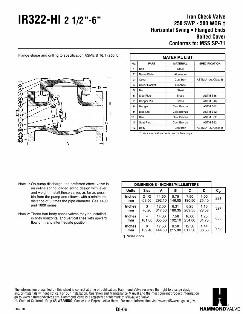
The information presented on this sheet is correct at time of publication. Hammond Valve reserves the right to change design and/or materials without notice. For our Installation, Operation and Maintenance Manual and the most current product information go to www.hammondvalve.com. Hammond Valve is a registered trademark of Milwaukee Valve.
State of California Prop 65 WARNING: Cancer and Reproductive Harm. For more information visit www.p65warnings.ca.gov.
BI-68
Iron Check Valve250 SWP - 500 WOG †
Horizontal Swing • Flanged EndsBolted Cover
Conforms to: MSS SP-71
IR322-HI 2 1/2”-6”
Flange shape and drilling to specification ASME B 16.1 (250 lb). MATERIAL LISTNo. PART MATERIAL SPECIFICATION
1 Bolt Steel
2 Name Plate Aluminum
3 Cover Cast Iron ASTM A126, Class B
4 Cover Gasket Graphite
5 Nut Steel
6 Side Plug Brass ASTM B16
7 Hanger Pin Brass ASTM B16
8 Hanger Cast Bronze ASTM B62
9 Disc Nut Cast Bronze ASTM B62
10 1 Disc Cast Bronze ASTM B62
11 Seat Ring Cast Bronze ASTM B62
12 Body Cast Iron ASTM A126, Class B
1 6” discs are cast iron with bronze face rings.
Rev 10
Note 1: On pump discharge, the preferred check valve is an in-line spring loaded swing design with lever and weight. Install these valves as far as possi-ble from the pump and elbows with a minimum distance of 5 times the pipe diameter. See 1400 and 1800 series.
Note 2: These iron body check valves may be installed in both horizontal and vertical lines with upward flow or in any intermediate position.
DIMENSIONS - INCHES/MILLIMETERS
Units Size A B C D CvInches
mm2 1/263.50
11.50292.10
5.75146.05
7.50190.50
1.0025.40 221
Inchesmm
376.20
12.50317.50
6.31160.35
8.25209.55
1.1328.58 327
Inchesmm
4101.60
14.00355.60
7.56192.10
10.00254.00
1.2531.75 605
Inchesmm
6152.40
17.50444.50
8.50215.90
12.50317.50
1.4436.53 975
† Non-Shock

The information presented on this sheet is correct at time of publication. Hammond Valve reserves the right to change design and/or materials without notice. For our Installation, Operation and Maintenance Manual and the most current product information go to www.hammondvalve.com. Hammond Valve is a registered trademark of Milwaukee Valve.
State of California Prop 65 WARNING: Cancer and Reproductive Harm. For more information visit www.p65warnings.ca.gov.
BI-69
Iron Gate Valve125 SWP - 200 WOG †
3% Nickel Iron BodyOS & Y • Solid Wedge Disc
Bolted Bonnet • Flanged EndsS.S. Trim
Conforms to: MSS SP-70
IR1913-HI 2”-12”
MATERIAL LISTNo. PART MATERIAL SPECIFICATION
1 Stem ASTM A182 F3162 Handwheel Nut Steel or Ductile Iron ASTM A3953 Name Plate Aluminum4 Yoke Bushing Ductile Iron ASTM A3955 Handwheel Cast Iron ASTM A126, Class B6 Bonnet Cap Nut Steel7 Bonnet Cap Ductile Iron ASTM A395
8 1 Bonnet 3% Nickel Iron9 Bonnet Cap Bolt Steel
10 Gland Follower Nut Steel11 Gland Follower Ductile Iron ASTM A39512 Packing Gland ASTM B276-31613 Packing Graphite14 Gland Follower Bolt Steel15 Backseat Bushing ASTM B 276-31616 Body Nut Steel17 Body Bolt Steel18 Wedge Pin ASTM B276-31619 Body 3% Nickel Iron20 Seat Ring ASTM A351 CF8M21 Wedge Face Ring ASTM A351 CF8M22 Wedge 3% Nickel Iron23 Body Gasket Graphite Non-Asb. Fibers24 Stem Collar ASTM B276-316
25Grease Fitting(not shown)
Steel
1 Sizes through 8” made with yoke integral with bonnet. 10” and 12” sizes made with separate yoke bolted to bonnet. Suffix HI – Signifies “Hammond” International Series Valves.
Rev 8
DIMENSIONS - INCHES/MILLIMETERS
Units Size A B C D E CvInches
mm2 7.00
17815.00381
7.00178
6.00152
0.6316 215
Inchesmm
2 1/2 7.50191
16.88429
7.00178
7.00178
0.6917 335
Inchesmm
3 8.00203
18.75476
8.00203
7.50191
0.7519 510
Inchesmm
4 9.00229
22.75578
10.00254
9.00229
0.9424 945
Inchesmm
5 10.00254
27.13689
12.00305
10.00254
0.9424 1525
Inchesmm
6 10.50267
30.13765
12.00305
11.00279
1.0025 2250
Inchesmm
8 11.50292
40.131019
14.00356
13.50343
1.1329 4150
Inchesmm
10 13.00330
48.251226
16.00406
16.00406
1.8146 6700
Inchesmm
12 14.00356
56.881445
18.00457
19.00483
1.2532 9925
Also available in 14”, 16”, 18”, 20” and 24” on special order.150 psi non-shock cold water, oil or gas.
Note 1: The wetted surface of this product con-tacted by consumable water contains less than one quarter of one percent (.25%) of lead by weight. Meets the requirements of Senate law S.3874.

The information presented on this sheet is correct at time of publication. Hammond Valve reserves the right to change design and/or materials without notice. For our Installation, Operation and Maintenance Manual and the most current product information go to www.hammondvalve.com. Hammond Valve is a registered trademark of Milwaukee Valve.
State of California Prop 65 WARNING: Cancer and Reproductive Harm. For more information visit www.p65warnings.ca.gov.
BI-70
Iron Check Valve125 SWP - 200 WOG †
3% Nickel Iron BodyBolted Bonnet • Flanged Ends
S.S. TrimConforms to: MSS SP-71
IR1937-HI 2”-12”
This check valve may be installed in both horizontal and vertical lines with upward flow or in any intermediate postion.
Note 1: The check valve may be installed in both horizon-tal and vertical lines with upward flow or in any intermediate position.
Note 2: On pump discharge, the preferred check valve is an in-line spring loaded, swing design with lever and weight. Install these valves as far as possi-ble from the pump and elbows and at a minimum length of 5 times the pipe diameter. See 1400 and 1800 series.
Note 3: The wetted surface of this product contacted by consumable water contains less than one quarter of one percent (.25%) of lead by weight. Meets the requirements of Senate law S.3874.
MATERIAL LISTNo. PART MATERIAL SPECIFICATION
1 Bolt Steel ASTM A307 Gr. B
2 Name Plate Aluminum
3 Cover 3% Nickel Iron ASTM A126, Class B
4 Cover Gasket Graphite
5 Nut Steel
6 Side Plug ASTM A276-316
7 Hanger Pin ASTM A276-316
8 Hanger ASTM A351-CF8M
9 Disc Nut ASTM A194-8M
10 Disc ASTM A351-CF8M
11 Seat Ring ASTM A351-CF8M
12 Body 3% Nickel Iron ASTM A126, Class B
Rev 7
DIMENSIONS - INCHES/MILLIMETERS
Units Size A B C D CvInches
mm2 8.00
2033.94100
6.00152
0.6316 137
Inchesmm
2 1/2 8.50216
4.50114
7.00178
0.6917 221
Inchesmm
3 9.50241
5.13130
7.50191
0.7519 327
Inchesmm
4 11.50292
6.13156
9.00229
0.9424 605
Inchesmm
5 13.00330
6.81173
10.00254
0.9424 975
Inchesmm
6 14.00356
8.00203
11.00279
1.0025 1440
Inchesmm
8 19.50495
9.44240
13.50343
1.1329 2670
Inchesmm
10 24.50622
12.06306
16.00406
1.1930 4300
Inchesmm
12 27.50699
16.13410
19.00483
1.2532 6350
Suffix HI – Signifies International Valves.

The information presented on this sheet is correct at time of publication. Hammond Valve reserves the right to change design and/or materials without notice. For our Installation, Operation and Maintenance Manual and the most current product information go to www.hammondvalve.com. Hammond Valve is a registered trademark of Milwaukee Valve.
State of California Prop 65 WARNING: Cancer and Reproductive Harm. For more information visit www.p65warnings.ca.gov.
BI-71
CLIP GATE 2887-M, 2888-MIRON
Inside Screw • Rising Stem • Solid WedgeGland Packed • Class 150
Units Size A B C D NET WT. LBS.
Inches 1/4 5.00 2.09 2.12 0.46MM 6.35 127.00 53.09 53.85 11.68
Inches 1/2 5.00 2.09 2.12 0.46MM 12.70 127.00 53.09 53.85 11.68
Inches 3/4 6.21 2.35 2.43 0.50MM 19.05 157.73 59.69 61.72 12.70
Inches 1 7.50 2.40 2.95 0.62MM 25.40 190.50 60.96 74.93 15.75
Inches 1 1/4 9.00 2.87 2.95 0.70MM 31.75 228.60 72.90 74.93 17.78
Inches 1 1/2 9.14 3.14 3.15 0.75MM 38.10 232.16 79.76 80.01 19.05
Inches 2 11.57 3.70 3.75 0.75MM 50.80 293.88 93.98 95.25 19.05
Inches 2 1/2 12.87 4.17 4.76 0.90MM 63.50 326.90 105.92 120.90 22.86
Inches 3 14.67 4.56 6.00 0.90MM 76.20 372.62 115.82 152.40 22.86
Inches 4 19.20 5.76 9.00 0.98MM 101.60 487.68 146.30 228.60 24.89
16.0
24.0
48.0
3.0
5.0
6.5
10.0
DIMENSIONS - INCHES / MILIMETERS
1.5
2.0
1.5
www.milwaukeevalve.com
2887-M Bronze Trim2888-M All Iron
RATINGS150 PSI WSP225 PSI WOG (Non-Shock)125 PSI WSP175 PSI WOG (Non-Shock)
2887-M 2888-M
Ductile Iron - A536 Ductile Iron - A536
Ductile Iron - A536 Ductile Iron - A536
Cast Bronze - B62 Ductile Iron - A536
4 Handwheel Cast Iron - A126-B Cast Iron - A126-B5 Packing Nut Ductile Iron - A536 Ductile Iron - A5366 Gland Brass - B16 410 SS7 Stem Brass - B16 410 SS8 Gasket Commerical Commercial9 Packing Commerical Commercial
10 Nut Steel - A307-B Steel - A307-B11 U-Bolt Steel - A307-B Steel - A307-B
12 Name Plate Aluminum Aluminum
MATERIAL
MATERIAL LIST
SPECIFICATIONSThreaded Ends to ANSI B2.1.
PRESSURE RATINGSIZE
1/4 - 2
2 1/2 - 4
1 Body
DESCRIPTIONNO.
2 Bonnet
3 Disc
05/05 Printed on recycled paper with soy ink. t i - 63
The information presented on this sheet is correct at the time of publication. Milwaukee Valve reserves the right to changedesign, and/or material specifications without notice. For the most current information access www.milwaukeevalve.com
Suffix M – Signifies “MILVACO” Series International Values.
Iron Clip Gate Valve1/4” - 2” 150 SWP - 225 WOG †
2 1/2” - 4” 125 SWP -175 WOG †Inside Rising Stem • Solid Wedge Disc
Threaded Ends
IR337-HI 1/4”-4”
MATERIAL LISTNo. PART MATERIAL SPECIFICATION
1 Body Ductile Iron-A 536 Ductile Iron-A 536
2 Bonnet Ductile Iron-A 536 Ductile Iron-A 536
3 Disc Cast Bronze-B 62 Ductile Iron-A 536
4 Handwheel Cast Iron-A 126-B Cast Iron-A 126-B
5 Packing Nut Ductile Iron-A 536 Ductile Iron-A 536
6 Gland Brass-B 16 410 SS
7 Stem Brass-B 16 410 SS
8 Gasket Commercial Commercial
9 Packing Commercial Commercial
10 Nut Steel-A 307-A Steel-A 307-A
11 U-Bolt Steel-A 307-A Steel-A 307-A
12 Name Plate Aluminum Aluminum
Rev 9
DIMENSIONS - INCHES/MILLIMETERS
Units Size A B C D CvInches
mm1/4 - 1/2 5.00
1272.0953
2.1354
0.4712
5
Inchesmm
3/4 6.22158
2.5264
2.4462
0.5113
32
Inchesmm
1 7.50191
2.6461
2.9575
0.6316
54
Inchesmm
1 1/4 9.00229
2.9174
2.9575
0.7018
97
Inchesmm
1 1/2 9.14232
3.1580
3.7595
0.7519
135
Inchesmm
2 11.58294
3.9099
3.98101
0.7519
230
Inchesmm
2 1/2 12.88327
4.60117
4.75121
0.9023
337
Inchesmm
3 14.70375
4.92125
6.00152
0.9023
536
Inchesmm
4 19.30490
5.94151
9.00229
0.9825
960
Suffix HI – Signifies International Valves.† Non-Shock

The information presented on this sheet is correct at time of publication. Hammond Valve reserves the right to change design and/or materials without notice. For our Installation, Operation and Maintenance Manual and the most current product information go to www.hammondvalve.com. Hammond Valve is a registered trademark of Milwaukee Valve.
State of California Prop 65 WARNING: Cancer and Reproductive Harm. For more information visit www.p65warnings.ca.gov.
BI-72
Iron Silent Check Valve125 Class • Wafer Style
Stainless Steel TrimConforms to: MSS SP-125
IR9253 2”-10”
Note 1: The wetted surface of this product contacted by consumable water contains less than one quarter of one percent (.25%) of lead by weight.
Note 2: Valve is designed for liquid service only. Install 5 to 10 pipe diameters downstream from pump discharge or elbows to avoid flow turbulence. Valve is designed to be mated to standard steel flanges.
MATERIAL LISTNo. PART MATERIAL
1 Body Cast Iron, ASTM A126
2 Seat St. Steel, TYPE 304
3 Disc St. Steel, TYPE 304
4 Spring St. Steel, TYPE 304
5 Bushing St. Steel, TYPE 304
6 Screw St. Steel, TYPE 304
Rev 10
DIMENSIONS - INCHES/MILLIMETERS
Units Size A B CvInches
mm2 4.25
1082.6367
66
Inchesmm
2 1/2 5.00127
2.8873
88
Inchesmm
3 5.75146
3.1379
130
Inchesmm
4 7.00178
4.00102
228
Inchesmm
5 8.38213
4.75121
350
Inchesmm
6 9.75248
5.50140
520
Inchesmm
8 13.38340
6.50165
900
Inchesmm
10 16.00406
8.25210
1450
Sizes 2” thru 6” are combination ANSI Class125 and 250. 8” and 10” sizes are ANSI Class 125.

The information presented on this sheet is correct at time of publication. Hammond Valve reserves the right to change design and/or materials without notice. For our Installation, Operation and Maintenance Manual and the most current product information go to www.hammondvalve.com. Hammond Valve is a registered trademark of Milwaukee Valve.
State of California Prop 65 WARNING: Cancer and Reproductive Harm. For more information visit www.p65warnings.ca.gov.
BI-73
Iron Silent Check Valve125 Class • Globe Style
Stainless Steel TrimConforms to: MSS SP-125
IR9354 2 1/2”-42”
Note 1: Valve sizes 2 1/2” through 10” will mate up to wafer style butterfly valve without the use of spool pieces or other adaptors. (See “B” dimension for allowable clearance).
Note 2: Ductile iron trim with EPDM o-ring seal available upon request. Consult factory for pricing and availability.
Note 3: The wetted surface of this product contacted by consumable water contains less than one quarter of one percent (.25%) of lead by weight.
Note 4: Valve is designed for liquid service only.
Install 5 to 10 pipe diameters downstream from pump discharge or elbows to avoid flow turbulence. Valve is designed to be mated to flat faced steel flanges.
Rev 14
ANSI CLASS 125 ANSI CLASS 250
Units Size A B Cv Units Size A BInches
mm2 1/2 5.50
1401.1930 110 Inches
mm2 1/2 5.50
1401.4437
Inchesmm
3 6.00152
1.3835 155 Inches
mm3 6.00
1521.3835
Inchesmm
4 7.25184
1.7544 278 Inches
mm4 7.25
1841.7544
Inchesmm
5 8.50216
2.0051 435 Inches
mm5 8.50
2162.0051
Inchesmm
6 9.75248
2.5064 625 Inches
mm6 9.75
2482.5064
Inchesmm
8 12.50318
3.2583 1115 Inches
mm8 12.50
3183.2583
Inchesmm
10 15.50394
4.25108 1770 Inches
mm10 15.50
3944.25108
Inchesmm
12 14.25362
N/AN/A 2500 Inches
mm12 14.25
362N/AN/A
Inchesmm
14 15.75400
N/AN/A 3400 Inches
mm14 15.75
400N/AN/A
Inchesmm
16 17.63448
N/AN/A 4400 Inches
mm16 17.63
448N/AN/A
Inchesmm
18 18.75476
N/AN/A 5600 Inches
mm18 18.75
476N/AN/A
Inchesmm
20 20.63524
N/AN/A 6900 Inches
mm20 20.63
524N/AN/A
Inchesmm
24 24.00610
N/AN/A 10000 Inches
mm24 24.00
610N/AN/A
Inchesmm
30 29.25743
N/AN/A 15400 Inches
mm30 29.25
743N/AN/A
Inchesmm
36 45.001143
N/AN/A 22400 Inches
mm36 45.00
1143N/AN/A
Inchesmm
42 50.001270
N/AN/A 30400 Inches
mm42 50.00
1270N/AN/A
Max Non-Shock Working PSI125# ANSI B16.1 Flange Rating
Temperature
Size 150° F 200° F
2 1/2” - 12” 200 PSI 190 PSI
14” - 42” 150 PSI 135 PSI
Max Non-Shock Working PSI250# ANSI B16.1 Flange Rating
Temperature
Size 150° F 200° F
2 1/2” - 12” 400 PSI 370 PSI
14” - 42” 300 PSI 280 PSI
MATERIAL LISTNo. PART MATERIAL
1 Body Cast Iron, ASTM A126
2 Seat St. Steel, TYPE 304
3 Disc St. Steel, TYPE 304
4 Spring St. Steel, TYPE 304
5 Bushing St. Steel, TYPE 304
6 Screw St. Steel, TYPE 304