browsing, building, and beholding cyberspace
TRANSCRIPT
Browsing, Building, andBeholding Cyberspace
New Approaches to the Navigation, Construction, andVisualisation of Hypermedia on the Internet
Keith Andrews

Browsing, Building, and Beholding Cyberspace
New Approaches to the Navigation, Construction, andVisualisation of Hypermedia on the Internet
Dissertation for the Award of the Academic Degree
Doctor of Technical Sciences
at
Graz University of Technology
submitted by
Keith Andrews
Institute for Information Processing and Computer Supported New Media (IICM),Graz University of Technology
A-8010 Graz, Austria
September 1996
c Copyright 1996 by Keith Andrews
First Reader: o.Univ.-Prof. Dr. Dr.h.c. Hermann Maurer
Second Reader: ao.Univ.-Prof. Dr. Franz Aurenhammer


Das Browsen, Bauen und Betrachten von Cyberspace
Neue Ansatze zur Navigation, Konstruktion und Visualisierungvon Hypermediainformationen im Internet
Dissertation zur Verleihung des akademischen Grades
Doktor der Technischen Wissenschaften
an der
Technischen Universit¨at Graz
vorgelegt von
Keith Andrews
Institut fur Informationsverarbeitung und Computergest¨utzte neue Medien (IICM),Technische Universit¨at Graz
A-8010 Graz
September 1996
c Copyright 1996, Keith Andrews
Diese Dissertation ist in englischer Sprache verfaßt.
Erster Begutachter: o.Univ.-Prof. Dr. Dr.h.c. Hermann Maurer
Zweiter Begutachter: ao.Univ.-Prof. Dr. Franz Aurenhammer

Abstract
The Internet and the World Wide Web form a vast, global information network. This thesisdescribes new approaches to the navigation, construction, and visualisation of hypermedia on theInternet, as embodied in the Harmony client and authoring tool for the Hyper-G web server.
Harmony’s advanced browsing and navigational tools support the concept oflocation feedback,which helps users orient by providing contextual feedback with reference to an explicit structuralframework.
Harmony’s suite of (remote) authoring facilities includes structure editing, document editing,interactive graphical link editing in all media, attribute editing, interactive uploading, insertion, anddeletion, making annotations, and managing user accounts and user groups.
The Harmony 3D Scene Viewer was the first Internet-enabled, 3d hypermedia browser. Itssuccessor, VRweb, is a popular VRML browser with support for collision detection, terrain-following,point-of-interest navigation, and interactive link editing.
Finally, Harmony incorporates two innovative information visualisation tools. The HarmonyLocal Map is a dynamic, two-dimensional structure map which visualises link and membership rela-tionships. The Harmony Information Landscape is a three-dimensional landscape visualisation, whichutilises the three available dimensions to compactly present acombineddisplay of both hierarchicalstructure and hyperlink relationships.


Kurzfassung
Das Internet und das World Wide Web stellen ein gewaltiges, globales Informationsnetz dar.Diese Dissertation beschreibt neue Ans¨atze zur Navigation, Konstruktion und Visualisierung vonHypermediainformationen im Internet, wie sie im Harmony Client bzw. Editierwerkzeug f¨ur denHyper-G Web-Server integriert worden sind.
Harmony besitzt anspruchsvolle M¨oglichkeiten zum Browsen und Navigieren. Inbesondereermoglicht Location Feedbackden Benutzern eine Orientierungshilfe, indem eine st¨andige kontext-bezogene R¨uckmeldung erfolgt.
Harmonys Editierwerkzeuge erm¨oglichen unter anderem das Editieren (auch ¨uber das Internet)von hierarchischen Strukturen, Dokumenten, Hyperlinks, Attributen, Annotationen, das Einspielenund Loschen von Dokumenten, und die Verwaltung von Benutzer-Accounts und Benutzergruppen.
Der Harmony 3D Scene Viewer war der erste Browser f¨ur 3D-Modelle mit Hyperlinks ¨uberdas Internet. Sein Nachfolger, VRweb, ist ein beliebter VRML-Browser, samt Collision Detection,Point-of-Interest Navigation und interaktivem Linkeditieren.
Schließlich besitzt Harmony zwei innovative Werkzeuge zur Informationsvisualisierung. DieHarmony Local Map ist eine dynamische 2D Strukturdarstellung der hierarchischen Zugeh¨origkeitund Hyperlinkverbindungen. Die Harmony Informationslandschaft ist eine 3D Visualisierung, dieeinekombinierteDarstellung sowohl der hierarchischen Struktur als auch der Hyperlinkverbindungenermoglicht.


I hereby certify that the work presented in this thesis is my own and that work performed by others isappropriately cited.
Ich versichere hiermit, diese Arbeit selbstandig verfaßt, andere als die angegebenen Quellen undHilfsmittel nicht benutzt und mich auch sonst keiner unerlaubten Hilfsmittel bedient zu haben.


Acknowledgements
I am indebted to my friends, colleagues, and students for their help, support, and teamworkover the past five years. Everyone at the IICM and IHM (the Institute for Hypermedia Systems ofJOANNEUM RESEARCH) has been ready to provide valuable help and feedback, often at a moment’snotice. Above all, Hermann Maurer’s leadership, vision, and fund-raising talents, Frank Kappe’s tech-nical prowess, and Gerhard Pail’s managerial skills combined to make the IICM the ideal place, andHyper-G the ideal platform, upon which to base my work. Many thanks also to Franz Aurenhammerfor agreeing to be second reader of this thesis.
Special mention and thanks go to the members, past and present, of the Harmony and VRwebproject teams, and to the current members of my information visualisation team, including: ManfredBrandl, Ingmar Egger, Martin Eyl, Mansuet Gaisbauer, G¨unther Geiger, Peter Kogler, Gunter Laky,Sieghard Lettner, Bernhard Marschall, Susanne Mayr, Vanessa Mayrhofer, Martin Melcher, GeorgMeszaros, Alexander Nußbaumer, Gerbert Orasche, Alexander Passer, Andreas Pesendorfer, MichaelPichler, Peter Pichler, Alexander Rodiga, Karin Roschker, J¨urgen Schipflinger, Klaus Schmaranz,Johannes Schmeja, Christine Schuster, Claudia Windisch, and Peter Wolf.
I have benefitted from fruitful discussion with, and have been inspired by, many colleagues fromaround the world, including: Robert Cailliau, Wolfgang Dalitz, Hugh Davis, Andreas Dieberger,Gitta Domik, Dieter Fellner, Jim Foley, Ed Fox, Nahum Gershon, Ed Grossman, Michael Gruber,Joseph Hardin, Keith Instone, Larry Jackson, Franz Leberl, Mark McCahill, Sougata Mukherjea,Jakob Nielsen, Steve Poltrock, Jenny Preece, Dan Russell, Jodok Sch¨affler, Wolfgang Schinagl, BenShneiderman, and Andy Wood.
Much of the early work on Hyper-G was supported by the Austrian Ministry for Science andResearch, byJOANNEUM RESEARCH, and through projects with the European Space Agency. Thework on 3d hypermedia and on information visualisation was financed in part by the AnniversaryFund of the Austrian National Bank under project number 5334 “Virtual Information Spaces”.
Last, but not least, I would like to thank my wife Elisabeth, and children David and Kristin, fortheir love and patience while I was travelling and working long weekends, and Rob and Rich Cheeseand all my friends in Graz for making it such a great place to live . . .
Keith AndrewsGraz, Austria, September 1996
i

ii

Credits
� Parts of Chapter 4 are based on papers co-authored with Hermann Maurer, Frank Kappe, andKlaus Schmaranz [Andrewset al., 1995c,e,g].
� Parts of Chapter 7 are based on papers co-authored with Michael Pichler, Gerbert Orasche, EdGrossman, and Mark McCahill [Pichleret al., 1995; Andrews and Pichler, 1996].
� Part of Chapter 8 is based on a paper co-authored with Michael Pichler and Peter Wolf [Andrewset al., 1996].
� Figure 4.3 was drawn by Frank Kappe.
� Figure 8.2 is copyrightc 1996 Ben Shneiderman, University of Maryland, and is used withpermission.
� Figure 8.3 is copyrightc 1996 Xerox PARC and is used with permission.
� Figure 8.7 is copyrightc 1996 Andreas Dieberger and is used with permission.
� Figure 8.10 is copyrightc 1995 Andy Wood, University of Birmingham, and is used with per-mission.
� Figure 8.13 is copyrightc 1995 Sougata Mukherjea, Georgia Institute of Technology, and isused with permission.
� Figure 8.14 is copyrightc 1996 Tim Bray, Open Text Corporation, and is used with permission.
� Figure 8.15 is copyrightc 1996 Communications Research Group, University of Nottingham,and is used with permission.
� Figure 8.16 is copyrightc 1996 Communications Research Group, University of Nottingham,and is used with permission.
iii

iv

Contents
1 Introduction 1
2 Information Systems and the Internet 32.1 The Internet 32.2 Basic Internet Services 62.3 Archie 72.4 WAIS 72.5 The Internet Gopher 82.6 The World Wide Web 92.7 Further Reading 11
3 Hypermedia Systems 133.1 What is Hypertext and Hypermedia? 133.2 The Origins of Hypermedia 143.3 Types of Hypermedia System 163.4 When to use Hypermedia 173.5 Navigating Hyperspace 183.6 Further Reading 21
4 Hyper-G – A Second Generation Web Server 234.1 The Evolution of Hyper-G 234.2 The Need for “Second Generation” Web Systems 244.3 The Design of Hyper-G 294.4 The Architecture of Hyper-G 314.5 The Hyper-G Server 334.6 Hyper-G Clients 344.7 Hyper-G Tools and Utilities 374.8 Serving to the Web with Hyper-G 384.9 Applications of Hyper-G 414.10 Further Reading 42
5 Browsing Cyberspace with Harmony 455.1 Designing a Graphical Hypermedia Client 455.2 The Architecture of Harmony 465.3 Browsing Collections, Clusters and Documents with Harmony 475.4 Harmony’s Document Viewers and Hyperlink Navigation 525.5 The Harmony Local Map 635.6 Searching in Harmony 655.7 Harmony’s History Browser 685.8 Harmony for WWW and Gopher Sites 695.9 Harmony System Functions 705.10 Harmony Options and Preferences 715.11 Multilingual Support 725.12 System Status and Communication with Other Users 735.13 Further Reading 76
v

6 Building Cyberspace with Harmony 776.1 Moving Beyond the Provider-Consumer Paradigm 776.2 Object and Document Creation 786.3 Document Editing 836.4 Modifying Attributes 866.5 Interactive Link Editing 886.6 Structure Editing 986.7 Deleting Objects 1006.8 Annotations 1006.9 Managing Users and User Groups 1026.10 Further Reading 104
7 Beholding Cyberspace with VRweb 1057.1 3D Hypermedia and the Internet 1057.2 The Evolution of VRweb 1067.3 The Virtual Reality Modeling Language (VRML) 1077.4 The VRweb VRML Browser 1087.5 The VRweb User Interface 1087.6 VRweb and Web Browsers 1117.7 VRweb’s Software Architecture 1137.8 Beholding Cyberspace with VRweb 1157.9 Further Reading 115
8 Visualising Cyberspace in Harmony 1178.1 Visualising Information Spaces 1178.2 Types of Information Visualisation 1178.3 Examples of Information Visualisation 1198.4 FSN and SGI’s Information Landscape Patent 1228.5 Visualising Cyberspace 1228.6 Hyper-G’s Rich Infrastructure for Visualisation 1308.7 The Harmony Local Map 1318.8 The Harmony Information Landscape 1348.9 Further Reading 139
9 Outlook 1419.1 General Trends 1419.2 Work in Progress 1419.3 Ideas for Future Work 143
10 Concluding Remarks 145
Bibliography 147
vi

List of Figures
3.1 Linear text and hypertext. 13
3.2 Nodes, links, and anchors. 14
4.1 The Hyper-G data model. 30
4.2 The client-server architecture of Hyper-G. 32
4.3 The architecture of the Hyper-G server. 33
4.4 The Harmony client and authoring tool for X Windows. 34
4.5 The Amadeus client and authoring tool for Microsoft Windows. 35
4.6 Editing a HTML text document through Amadeus. 35
4.7 The Hyper-G Terminal Viewer hgtv . A simple terminal-based Hyper-G client whichcan be used for example across a telnet connection. Here a Hyper-G collection isbeing displayed. 36
4.8 A text document displayed by hgtv . Note that hyperlinks are followed by typing num-bers, since simple terminals do not support mouse clicking. 36
4.9 Easy, Hyper-G’s public terminal viewer, designed with large interface buttons fortouch-screen use. 37
4.10 The IICM welcome page, seen through the eyes of Netscape. The welcome documentis a full collection head, containing embedded links to its siblings and children, hencethe collection area is not present (the middle of the page has been clipped out for abetter overview). 39
4.11 The Hyper-G search panel. 40
4.12 Hyper-G search results. Full text matches are ranked in decreasing order of relevance. 41
4.13 The Hyper-G Gateway Interface (HGI). 42
4.14 The European Space Agency’s Earth Observation Guide and Directory Service (herethe top half of the welcome page). 43
4.15 The European Space Agency’s Earth Observation Guide and Directory Service (herethe bottom half of the welcome page). Note the collection area, listing the membersof the current collection. 44
5.1 The architecture of Harmony client and authoring tool for Hyper-G. 46
5.2 The Harmony client and authoring tool for Hyper-G. 47
5.3 The Harmony Session Manager. 48
5.4 The Harmony Attributes window. 51
5.5 The Harmony Text Viewer displaying a HTML document. 54
5.6 The Text Viewer Settings Panel. 56
5.7 The Text Viewer Font Chooser. 56
5.8 The Harmony Image Viewer. 57
5.9 Links in image documents. 57
5.10 Image Viewer colour configuration. 58
5.11 The Harmony Film Player. 59
5.12 A destination anchor extending across the second half of a film clip. 59
5.13 The Film Player Settings Panel. 60
5.14 The Harmony Audio Player in native audio mode. 60
5.15 In NAS mode, the Harmony Audio Player also supports volume control and link anchors. 60
5.16 The Harmony PostScript Viewer. 61
vii

5.17 A destination anchor in the Harmony PostScript Viewer. The anchor region is high-lighted by dimming the rest of the page. 62
5.18 The Harmony VRweb 3D viewer. 625.19 A Harmony Telnet session to HYTELNET. 635.20 A Hyper-G Telnet object. 645.21 The Harmony Local Map. 645.22 The Harmony Search Dialogue. 665.23 Location feedback from search results. 665.24 Harmony’s extended search options. 675.25 Combined content and attribute search. 675.26 Set of collections activated for search. 685.27 Activating local and remote collections for search. 685.28 The Harmony History Browser. 695.29 A Hyper-G remote object representing the WWW project page at W3C. 695.30 The WWW project page at W3C displayed in Harmony. 705.31 A Hyper-G remote object representing a Gopher menu at the University of Min-
nesota’s Gopher server. 715.32 The Gopher menu displayed as a collection tree in Harmony. 715.33 The Harmony Identify dialogue. 725.34 The Harmony Change Password dialogue. 725.35 The Harmony Language Preference dialogue. 735.36 The Harmony Default Sort Order dialogue. 735.37 Harmony’s multilingual support. The user is about to change the language preference
order, currently first English then German, to the reverse. 745.38 Harmony’s multilingual support. Both the user interface and the information content
have now changed to German. 745.39 The Harmony Status Browser. 755.40 Sending messages between users in Harmony. 75
6.1 Keith Andrews’ home collection, where objects will be inserted. 786.2 Inserting a collection with the Harmony Insert Dialogue. 796.3 Inserting a cluster. 796.4 Uploading a text document. 806.5 The newly uploaded text document. 816.6 Inserting an image document. 826.7 Inspecting the new image document. 826.8 Inserting a remote WWW document. 836.9 Viewing the remote WWW object just inserted. 846.10 Editing a text with Emacs from the Harmony Text Viewer. 856.11 Editing a HTML text with AsWedit from the Harmony Text Viewer. 856.12 Editing an image with XV. 866.13 The Harmony Attribute Window. 876.14 Editing attributes in the Attribute Window. 876.15 Attributes of an anchor object. 886.16 Interactive definition of a source anchor in a text document. 896.17 The Harmony Link Creator. 896.18 The entire link creation procedure in Harmony. 906.19 Placing an inline image. The inline image is inserted directly preceding the selected
region, here the word “Graz”. 916.20 The Link Creator for an inline image. 916.21 The inserted inline image. 92
viii

6.22 The finished introductory page with three inline images. 926.23 Source anchors in an image document. 936.24 Elliptical destination anchor in an image document. 946.25 Creating an anchor in a film clip. 946.26 Frame range as a destination anchor. 956.27 Destination anchor in an audio document. 956.28 Creating a destination anchor in a PostScript document. 966.29 Creating a source anchor in a 3d model. 976.30 Attributes of the Schloßberg anchor object. 986.31 Editing the anchor’s attributes. 986.32 Moving a document or collection. 996.33 “Copying” a document or collection. 1006.34 Deleting a document or collection. 1006.35 Creating an annotation to the Introducing Graz cluster. 1016.36 The finished annotation. 1016.37 The annotation relationship in the Local Map. 1026.38 Structured discussion using annotations. 1036.39 HarAdmin, the graphical administration tool for user accounts and user groups. 103
7.1 Poster at ECHT’92 in Milan, December 1992: “Using 3D Scenes as HypermediaNodes”. 106
7.2 An example of a typical VRML 1.0 geometry file (shortened for brevity). 1077.3 The VRweb VRML viewer displaying Lightscape’s model of Jerusalem City Hall. 1097.4 VRweb for Windows in Heads-Up navigation mode. Icons are overlaid atop the view-
ing area for looking, walking, vertical/sideways motion, and point-of-interest naviga-tion. The rendering mode may be set separately for faster interactive navigation. 109
7.5 VRweb for UNIX in Fly Mode through VirtualSOMA. The speed of flight is overlaid inthe bottom right corner of the viewing area, the direction of flight is determined by theposition of the cursor relative to the central target crosshairs. 110
7.6 VRweb as a helper application with Mosaic for Windows. 1117.7 VRweb for UNIX and the Harmony client for Hyper-G. The user is navigating through
a virtual model of the city of Graz. In the background are the Harmony SessionManager and 3D Information Landscape. 112
7.8 VRweb for Windows and the Amadeus client for Hyper-G. 1137.9 VRweb’s software architecture. 1147.10 Dow Jones Visualisation: A dynamic 3d visualisation of the Dow Jones Industrial
Average displayed in VRweb. Screen shot of a VRML model generated by VisibleDecisions Inc. 116
7.11 Information landscape in VRML: visualising the structure of a Hyper-G server by gen-erating VRML. 116
8.1 Virtual Tourist II: a map-based interface to local and regional tourist information. 1198.2 Tree Map: visualising large hierarchies by successive horizontal and vertical partition-
ing. This tree map illustrates the Dewey Decimal Classification System. Copyrightc 1996 Ben Shneiderman, University of Maryland, used with permission. 120
8.3 Hyperbolic Map: mapping a large hierarchy to the surface or a sphere using hyper-bolic geometry. Copyright c 1996 Xerox PARC, used with permission. 121
8.4 Discovery Head Trader: A dynamic visualisation of the trading floor at a brokeragehouse. Individual traders’ desks are spread across the floor, the walls display sum-maries of performance and market conditions. Screen shot of a VRML model byVisible Decisions Inc. 121
8.5 FSN: The File System Navigator uses a landscape metaphor to visualise the hierar-chical structure of a file system. 123
ix

8.6 FSN: A selected file is brought under a virtual spotlight. 1238.7 The Vortex: A personal workspace for organising pointers to World Wide Web re-
sources. Copyright c 1996 Andreas Dieberger, used with permission. 1248.8 GopherVR: A landscape visualisation of the hierarchical menu structure of a Gopher
space. The entries of a menu are arranged around a central pillar representing theparent. 124
8.9 GODOT: Spatial coordinates are assigned as attributes to Gopher+ menu entries andare visualised in GopherVR. 125
8.10 HyperSpace: a self-organising 3d map of documents and links in a WWW spacebased on simulated annealing. Copyright c 1995 Andy Wood, University of Birming-ham, used with permission. 126
8.11 WebView: Java-based simulated annealing visualisation of WWW space. This is amap of Graz University of Technology Computer Centre’s web site. 126
8.12 MAPA: a Java-based visualisation of a hierarchical map of WWW space. The Webspace here is the Dynamic Diagrams web site. 127
8.13 The Navigational View Builder: A synthetic cone-tree style hierarchy map of a website generated by a combination of structure and attribute analysis. Copyright c 1995Sougata Mukherjea, Georgia Institute of Technology, used with permission. 128
8.14 A visualisation of the biggest and most visible sites on the Web, using data in theOpen Text robot-generated index of the Web. Copyright c 1996 Tim Bray, Open TextCorporation, used with permission. 128
8.15 The Internet Foyer. A navigable, populated visualisation of a Web site, showing vis-itors to the site as 3d avatars. Copyright c 1996 Communications Research Group,University of Nottingham, used with permission. 129
8.16 The Internet Foyer is a “mixed reality” application, integrating a real and a virtual foyer.Copyright c 1996 Communications Research Group, University of Nottingham, usedwith permission. 129
8.17 The Harmony Local Map, showing UNIX manual pages within two links of the grepmanual page. 131
8.18 Local map of inline image relationships. 132
8.19 Using the local map to determine where an inline image is used. 1328.20 The Local Map Options Panel set for parent/child relationships. 1338.21 Multiple paths in the Collection Browser. 1338.22 Local map of parent–child relationships for the collection “The Provincial Arsenal in
Graz”. 1338.23 The Harmony Information Landscape. Blocks on the plane represent collections and
clusters. The default style represents various types of document with simple 3d icons. 1358.24 Document clusters containing text and image documents. Note the overview window
in the top right, the arrow indicating the user’s position and orientation. 1358.25 Looking back to view the parents of a collection. 1368.26 Superimposing hyperlink relationships upon the structure map. Links to and from the
image “Map of Graz” have been selected for display. Documents having links to thisimage are displayed on the lower plane. Documents or collections reachable from theimage are displayed in the upper plane. 136
8.27 Arcs linking objects to their actual locations in the collection structure. Clicking an arcflies the user gently down the path to the appropriate location. 137
8.28 A geometrically more complicated set of document icons and the 3d icon chooser(top right). 138
8.29 Textured information landscape. Thumbnail images pasted to nearby document iconsgive an indication of their content. “Landmark” 3d icons representing whole collectionswill be visible from afar. 138
x

List of Tables
2.1 The development of the Internet. 4
2.2 The four basic Internet services. 7
3.1 Milestones in the history of hypermedia. 17
4.1 Some of the commands available in HG-CSP, Hyper-G’s client-server protocol. 324.2 Some of the low-level tools and utility scripts available to Hyper-G server administrators. 38
5.1 Typical icons used for Hyper-G objects in Harmony. 495.2 Typical icons used in the Harmony Session Manager’s toolbar. 525.3 Keyboard support in the Harmony Session Manager. 53
xi

xii

1 Introduction
“Cyberspace. A consensual hallucination experienced daily by billions of legitimate op-erators, in every nation, . . . A graphic representation of data abstracted from the banks ofevery computer in the human system. Unthinkable complexity. Lines of light ranged in thenonspace of the mind, clusters and constellations of data. Like city lights, receding. . . ”
William Gibson, Neuromancer, 1984
In his 1984 science-fiction novel, Neuromancer [Gibson, 1984], William Gibson described aglobal information network interfaced with a three-dimensional graphical visualisation and coinedthe termcyberspaceto describe it. Today, the Internet and the World Wide Web form a vast, globalinformation network. Information visualisation techniques are emerging and powerful graphics hard-ware is becoming available on desktop computers. In a sense, Gibson’s vision of cyberspace is in themaking.
In this thesis, I will describe new approaches to the navigation, construction, and visualisationof hypermedia on the Internet — the browsing, building, and beholding of cyberspace, respectively— with which I have been personally involved over the past five years.
The next chapter, Chapter 2, introduces the Internet and describes the information systems whichlead up to the “Web” as we know it today. In Chapter 3, I present an overview of hypermedia andhypermedia systems, of which the Web is just one, albeit well-known, example. Chapter 4 describesHyper-G, the “second generation” web server, developed at Graz University of Technology, whichserves as the platform for my work1.
Chapters 5, 6, 7, and 8 form the body of the thesis and largely describe my original work.Chapter 5 discusses the advanced browsing and navigational tools implemented in the Harmony clientand authoring tool for Hyper-G, for which I was project leader until the summer of 1995. Of particularnote are the synchronised, correlated navigational views which provide contextual feedback (which Icall location feedback) and help users orient themselves in large information spaces.
Chapter 6 covers Harmony’s sophisticated structuring, management, and authoring facilities.The notable contribution of Harmony in this respect is its suite of (remote) facilities for structureediting, document editing, interactive graphical link editing in all media, attribute editing, interac-tive uploading, insertion, deletion, making annotations, and managing user accounts and user groups.Most of these facilities have been available in Harmony since 1993 and 1994 and are only now be-ginning to become available in other Web packages.
The Harmony 3D Scene Viewer and its successor, the VRweb VRML browser, are discussed inChapter 7. To my knowledge, my work on 3d hypermedia, combining 3d models and hyperlinkingacross the Internet, was the first such work world-wide and pre-dates equivalent facilities in VRML(Virtual Reality Modeling Language) by more than two years.
Chapter 8 introduces the field of information visualisation and presents the two innovative vi-sualisation tools developed for Harmony. The Harmony Local Map is a dynamic, two-dimensionalstructure map to visualise the link and membership relationships in the vicinity of a particular docu-ment or collection. The Harmony Information Landscape is a three-dimensional landscape visuali-sation of the collection structure of a Hyper-G Web server. Particularly significant is thecombineddisplay of both hierarchical structuring and hyperlink relationships inonevisualisation, utilising thethree available dimensions to compactly present both kinds of structure.
Finally, Chapter 9 discusses current trends, describes work in progress, and outlines some of myideas for future work and research.
1There is a commercial version of Hyper-G called HyperWave, but I will generally use the term Hyper-G, except whenreferring explicitly to the commercial version.
1

2 INTRODUCTION

2 Information Systems and the Internet
This chapter gives an introduction to the Internet and Internet information systems. Anearlier version of this chapter was published as Chapter 2 of HyperWave: The Next Gen-eration Web Solution, Addison-Wesley, May 1996 [Andrews, 1996d].
2.1 The InternetThe Internet, the worldwide computer network, now connects almost 12.9 million individual comput-ers (July 1996) with a growth rate of around 100% per year [Network Wizards, 1996]. Estimates ofthe number of regular users of the Internet vary from 20 million to 50 million. If current growth rateswere to continue, the whole of the world population would be connected by the year 2004!
Around 18 Terabytes of information (18 000 000 000 000 bytes) traversed the main US backboneof the network, the NSFNET, in the month of November 1994 [Merit NIC, 1996], a figure which wasalso double that of the previous year1. These statistics highlight the immense social and economicsignificance which the Internet is attaining. More and more businesses are realising the enormouspotential of the Internet: in the summer of 1994, the number of commercial sites in the United Statesovertook the number of educational sites and this trend continues today.
Over the past couple of years, with increasingly powerful desktop computers and heavy invest-ment in network bandwidth, attention has shifted significantly from traditional Internet services suchas electronic mail and file transfer to more appealing, but resource-hungry, information systems andinteractive services, which now account for more Internet traffic (in bytes) than any other Internet ser-vice. The World Wide Web has made the Internet into a household name and turned browser softwareinto a commodity.
The History of the Internet
The Internet began life as a research project of the US Department of Defense’s Advanced ResearchProjects Agency (ARPA). The original purpose was to build a communications system capable ofwithstanding partial fallout of nodes during a nuclear attack, through the use of automatic re-routing.The first remote terminal connection from the University of California at Los Angeles (UCLA) to theStanford Research Institute (SRI) was demonstrated in November 1969. From these humble begin-nings grew the ARPANET, a fully operational computer network, based on a host-to-host protocolcalled the Network Control Protocol (NCP), and running services such as remote login (telnet) and filetransfer (ftp). Electronic mail (email) was added as an afterthought, after two programmers decidedto send each other messages as well as data [Lynch and Rose, 1993].
By 1981 there were some 200 sites on the ARPANET. In order to link in other vendors’ physicalnetworks into one seamless network, a new standardised protocol, the Transmission Control Proto-col/Internet Protocol (TCP/IP), was developed. On “flag day,” 1 January, 1983, the whole ARPANETwas switched from NCP to TCP/IP protocol and the foundation for the Internet was laid. The in-clusion of the TCP/IP protocol suite into Berkeley UNIX around the same time and its subsequentadoption by the vendor community gave a major boost to the Internet.
In March 1986 the Internet had around 3000 sites, and the US National Science Foundation(NSF) initiated development of the NSFNET, connecting six NSF supercomputer centres, to provide
1In December 1994, NSFNET traffic began migrating to the new network architecture, for which no comparable statis-tics are available.
3

4 INFORMATION SYSTEMS AND THE INTERNET
Time Stage of Development
Early 1970s ARPANET, US military network, designed to withstand partialfallouts
Early 1980s TCP/IP introduced to connect diverse networks together; Ether-net LANs and workstations become popular, Berkeley UNIX sup-ports TCP/IP
Late 1980s NSFNET backbone
1992 Internet Society founded as ultimate authority
Today “The Net”, a network of networks
Table 2.1 The development of the Internet.
a major backbone communication service for the Internet. By late 1989, the Internet had grown toover 150 000 sites in North America, Europe, South America, Australasia and beyond.
The Internet Society (ISOC) was founded in January 1992 as a non-profit, voluntary body tooversee development of the Internet. It appoints a council of elders, the Internet Architecture Board(IAB), which coordinates various sub-committees. The Internet Engineering Task Force (IETF) de-velops new standards and recommends them to the IAB for approval.
Table 2.1 summarises the historical development of the Internet. Today, the Internet is a vast,self-regulating network of national, regional, campus and private networks based on the TCP/IP proto-col suite and various connecting gateways. This “network of networks” (currently more than 130 000individual networks) is funded bottom-up – everyone pays for their part. Although many govern-ments currently finance Internet connectivity for their educational and research institutions, the sheerdemands for connectivity mean this is now changing to more direct forms of accounting. Indeed, theInternet is becoming so pervasive that it is often referred to simply as The Net. The recent popularityand visibility of the World Wide Web on the Internet has introduced the term The Web, embracingthe sum of Internet services and becoming more or less synonymous with “The Net” and the Internet.
Internet Protocols
The Internet is a packet switched network. The underlying protocol, the Internet Protocol (IP), pro-vides envelopes or packets for up to 1500 bytes of data. Each packet is stamped with a unique sourceand destination address. Packets are passed through the Internet from router to router until they reachtheir destination. Like letters through the postal system, they occasionally get damaged or lost orarrive in a different sequence.
The Transmission Control Protocol (TCP) builds on the basic service provided by the IP. TCPbreaks messages larger than 1500 bytes into a sequence of small IP packets. On the receiving side,packets are collected, placed in order and their data extracted. Missing and corrupted packets areretransmitted. TCP creates the appearance of a dedicated link between sender and receiver, which In-ternet applications use to communicate and exchange data. To this end, TCP also defines the conceptof contact ports to be used by individual applications or services. The more common services usepermanently assigned, “well-known” port numbers by default (but usually can be configured to usean alternative port). Port numbers are assigned by another Internet body, the IANA (Internet AssignedNumber Authority).

THE INTERNET 5
Internet Addresses
Every computer (or host) on the Internet has a unique address; in the current version of IP (IPv4)Internet addresses are 32-bit numbers, in four 8-bit parts, for example129.27.153.10 . They aresplit between the network and host parts: so-called class A networks have a 1-byte network and a 3-byte host part (providing for up to 16 777 214 hosts per network), class B networks a 2-byte networkand a 2-byte host part (providing for up to 65 534 hosts per network), and class C networks a 3-bytenetwork and a 1-byte host part (providing for up to 254 hosts per network). Computers connected tothe same physical network generally all have the same network part plus their own unique host part.
Theoretically, 32 bits provide over 4 billion addresses. However, the address allocation methodin IPv4 is rather wasteful. For most organisations and companies, a class C network with 254 hostsis too limiting, leading to high demand for class B networks. Consequently, class B address spaceis almost exhausted. Furthermore, whereas IPv4 today serves what might be called the computermarket (connecting computers), there is in future expected to be huge demand for IP addresses fromall manner of portable and household devices, from telephones and television sets to toasters.
To solve this problem, and to introduce numerous other improvements, a new version of IP(called IPv6 or IPng) is being specified. IPv6 will have 128-bit addresses and a hierarchical ad-dressing mechanism. This is an extremely large address space, corresponding to approximately665 570 793 348 866 943 898 599 addresses per square meter of the Earth’s surface!
Domain Names
Since human beings are notoriously inadequate when it comes to remembering sequences of num-bers, a multi-level, hierarchical naming scheme, the Domain Name System (DNS), is available as analternative way of specifying computers on the Internet. Each level is called a domain and there maybe any number of domains in a name (although usually no more than five). Domains in a name areseparated by periods and become successively smaller from right to left. For example, the computernamedaw.com is the machine serving as the main access point to the Addison-Wesley PublishingGroup and is in the commercial domain. The machine’s Internet address is192.207.117.2 . Thecomputer sitting on my desk isfiicmds06.tu-graz.ac.at , a DECstation at Graz Universityof Technology, in the academic domain, in Austria. Its address is129.27.153.10 . There is aunique mapping from domain name to Internet address, but not vice versa. Several domain names(aliases) may, and often do, refer to the same physical machine. Aliases are particularly useful fornaming services in a machine-independent fashion. For example,ftp.aw.com , Addison-Wesley’sanonymous ftp archive, is in fact an alias foraw.com , but publicising the alias rather than the realdomain name or Internet address means that the ftp service can be moved to another machine simplyby changing the address for the alias, without causing any disruption in service.
The top-level (rightmost) domains currently in use consist of the original six domains:com(commercial),edu (educational),gov (government),mil (military), org (organisations), andnet(network resources), plus around 150 of the 300 or so international two-letter country codes such asuk (United Kingdom) orat (Austria). Responsibility for the registration of domain names at thesecond level has been delegated by the IANA to regional Network Information Centres: the RIPENCC in Europe, the AP-NIC in the Asia-Pacific region and the InterNIC for the USA and the restof the world. The name space at each lower level is controlled by the appropriate body, for exampledomains beneathtu-graz.ac.at are assigned by the Computer Centre at Graz University ofTechnology.
A common misconception is that the parts of a domain name correspond directly to parts ofthe Internet address – they do not. DNS name servers are used to look up the address correspondingto a particular domain name: if the local DNS server does not know the address itself, it asks theDNS server of the top-level domain for the address of the DNS server responsible for the next lowerdomain, and so on down the domain hierarchy until the actual Internet address is found.
There has been huge recent demand for domain names, particularly in the commercial domain.In June 1996, InterNIC registered almost 400 000 new second-level names in thecom domain, de-

6 INFORMATION SYSTEMS AND THE INTERNET
spite the introduction of a $50 a year registration fee in September 1995. Major companies whichoverlooked the emergence of the Internet as a new medium have found their favoured domain namesalready taken by unknown rivals. Speculators are registering likely names in advance, and trademarklawyers are working overtime to reclaim them. Joshua Quittner, a journalist with Wired magazine,registeredmcdonalds.com for fun in 1994 [Quittner, 1994] and asked readers to send in sugges-tions as to what to do with it. It has since been transferred to the hamburger chain. . . . To ease thedemand for names in thecomdomain and to open up the market to competition, IANA is planning toallocate dozens of new top-level domains to several new registration bodies by January 1997 [IANA,1996].
2.2 Basic Internet Services: Remote Login, File Transfer, Emailand Network News
Many Internet applications are two-part, client-server applications. Client programs are started byusers on their local machines. The client establishes a connection across the Internet (usually viaTCP) to a server on the remote host machine via a particular port. The host/port pair uniquely definesa particular server. If the server is not running, or is listening to another port, no connection can bemade. Communication follows according to an agreed protocol for that application; often multipleimplementations of a particular service are available.
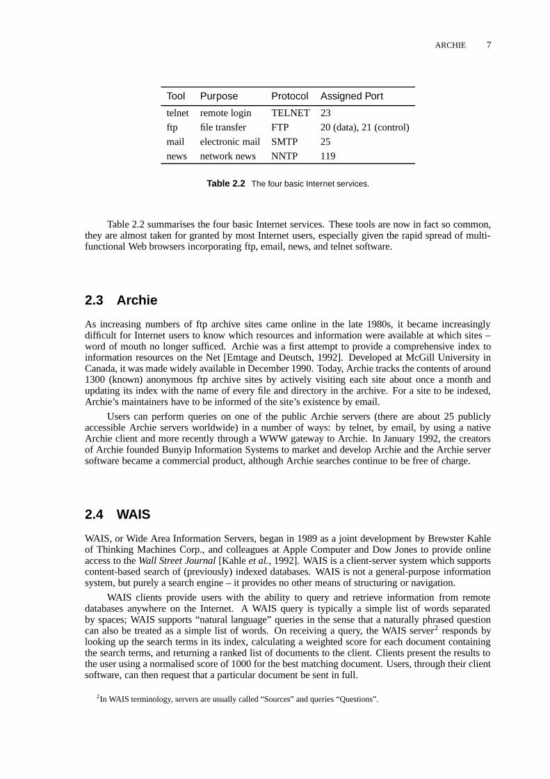
The four traditionally most widely used Internet applications are remote login, file transfer,electronic mail, and network news. The remote login tool telnet is a client-server application used tolog into another computer on the Internet. It provides a basic, terminal-style interface to the remotemachine.
The file transfer tool, ftp, is another client-server application, used to retrieve files from a remotemachine. Two kinds of access are possible: identified (with account and password) and anonymous(no account or password required). Most public archive sites operate anonymous ftp servers. Untilearly 1995, ftp data accounted for by far the largest amount of traffic on the Internet (about one thirdof the total traffic in bytes). A related service, Archie (discussed in Section 2.3), provides an indexingfacility for anonymous ftp archives, making it easier to find ftp resources.
Electronic mail (email) is arguably the most popular of all network services, and is not restrictedto just the Internet but can be exchanged via gateways with other networks like BITNET and UUCP.Email is not an “end to end” service like the previous applications, but a “store and forward” service:mail is passed from one machine to another until it reaches its destination. There are many mailprograms; most of them use the Simple Mail Transfer Protocol (SMTP). On the Internet, SMTPis implemented atop TCP. Commonly supported features include aliases, forwarding, carbon copiesand automatic reply. Mailing lists allow mail to be automatically directed to particular user groups.The MIME (Multi-purpose Internet Mail Extensions) specification defines how to include multimediaobjects in pieces of email, and ftp-to-email gateways allow files to be retrieved from ftp servers byemail.
Network News is the Internet equivalent of a discussion group or bulletin board. News is organ-ised hierarchically into broad topics called newsgroups dealing with particular themes, for examplecomp.lang.c++ for the C++ programming language. In general, anyone canposta message to anews group. The USENET comprises a set of voluntary rules for passing and maintaining newsgroupsin one of seven categories (comp being computer science). In addition, many “alternative,” commer-cial, and local newsgroup hierarchies also exist. News is passed from news server to news serveraccording to bilateral agreements between server administrators using the Network News TransferProtocol (NNTP). One of the main problems with news is the overwhelming amount of material – atypical news server might carry several thousand newsgroups and receive hundreds of megabytes ofnews per day! Another problem is that of “spamming”: postings to newsgroups which are off-topic,advertising, or simply rubbish. Some newsgroups aremoderatedfor this reason; a human being scansand approves each posting before passing it on to the newsgroup.
ARCHIE 7
Tool Purpose Protocol Assigned Port
telnet remote login TELNET 23
ftp file transfer FTP 20 (data), 21 (control)
mail electronic mail SMTP 25
news network news NNTP 119
Table 2.2 The four basic Internet services.
Table 2.2 summarises the four basic Internet services. These tools are now in fact so common,they are almost taken for granted by most Internet users, especially given the rapid spread of multi-functional Web browsers incorporating ftp, email, news, and telnet software.
2.3 Archie
As increasing numbers of ftp archive sites came online in the late 1980s, it became increasinglydifficult for Internet users to know which resources and information were available at which sites –word of mouth no longer sufficed. Archie was a first attempt to provide a comprehensive index toinformation resources on the Net [Emtage and Deutsch, 1992]. Developed at McGill University inCanada, it was made widely available in December 1990. Today, Archie tracks the contents of around1300 (known) anonymous ftp archive sites by actively visiting each site about once a month andupdating its index with the name of every file and directory in the archive. For a site to be indexed,Archie’s maintainers have to be informed of the site’s existence by email.
Users can perform queries on one of the public Archie servers (there are about 25 publiclyaccessible Archie servers worldwide) in a number of ways: by telnet, by email, by using a nativeArchie client and more recently through a WWW gateway to Archie. In January 1992, the creatorsof Archie founded Bunyip Information Systems to market and develop Archie and the Archie serversoftware became a commercial product, although Archie searches continue to be free of charge.
2.4 WAIS
WAIS, or Wide Area Information Servers, began in 1989 as a joint development by Brewster Kahleof Thinking Machines Corp., and colleagues at Apple Computer and Dow Jones to provide onlineaccess to theWall Street Journal[Kahle et al., 1992]. WAIS is a client-server system which supportscontent-based search of (previously) indexed databases. WAIS is not a general-purpose informationsystem, but purely a search engine – it provides no other means of structuring or navigation.
WAIS clients provide users with the ability to query and retrieve information from remotedatabases anywhere on the Internet. A WAIS query is typically a simple list of words separatedby spaces; WAIS supports “natural language” queries in the sense that a naturally phrased questioncan also be treated as a simple list of words. On receiving a query, the WAIS server2 responds bylooking up the search terms in its index, calculating a weighted score for each document containingthe search terms, and returning a ranked list of documents to the client. Clients present the results tothe user using a normalised score of 1000 for the best matching document. Users, through their clientsoftware, can then request that a particular document be sent in full.
2In WAIS terminology, servers are usually called “Sources” and queries “Questions”.

8 INFORMATION SYSTEMS AND THE INTERNET
WAIS is not restricted to text documents. Any body of documents which can be indexed (forexample, by file name, or by associated attribute fields or descriptions) can be made available throughWAIS, including images, PostScript files, video clips and so on.
A unique feature of WAIS is its support for relevance feedback: (parts of) text documents re-turned by a search which are deemed by the user to be particularly relevant can be used as input fora further search, in effect refining the search by asking WAIS to look for further similar documents.Newer versions of WAIS also support stemming (the automatic truncation of search terms), Booleanexpressions, partial word searches, and stop-lists (the automatic exclusion of non-productive fillerwords).
A problem for users of WAIS is to know which servers exist in the first place. The solutionprovided was the directory-of-servers database maintained (originally) by Thinking Machines, whichcontains entries describing all registered WAIS servers. This server can be searched to find otherservers with appropriate databases, resulting in a two-level search strategy. Since manually recordingserver names or repeatedly searching the directory of servers would rapidly become tedious, mostWAIS clients provide facilities for saving and re-using personal lists of servers. Most clients alsosupport personal lists of queries, so that accurate and successful queries can be periodically restartedwith minimal effort.
Most WAIS servers run on UNIX machines, although server software is also available forVAX/VMS. The WAIS package includes an indexing utility,waisindex , which extracts index termsfrom a body of documents and creates an inverted index structure (an alphabetical list of terms, eachwith an associated list of documents in which the term appears). A sophisticated data structure (atwo-level B-tree) provides fast access to the index. Thewaisindex utility automatically recognisesand indexes a wide range of text formats. Other document types, such as images, can be indexed byfile name orwaisindex can be customised to index associated descriptions, attributes, and so on.For standard text documents the inverted index takes up approximately the same amount of disk spaceas the original data set. Once an inverted index has been created,waisserver is started to serveclient requests.
WAIS clients and servers communicate using a binary protocol derived from the Z39.50-88(1988) ANSI Draft Standard for bibliographic retrieval and by default WAIS uses port 210, the portassigned to Z39.50. Communication is stateless, no state being retained by the server between trans-actions with a client. The Z39.50-88 standard was superseded in 1992 by the much improved, butincompatible, Z39.50-92 protocol, which has now itself been superseded by Z39.50-1995. In the sum-mer of 1992, WAIS Inc. was formed to develop WAIS commercially, and support and developmentof the public-domain WAIS (called freeWAIS [CNIDR, 1994]) passed to CNIDR (the Clearing housefor Networked Information Discovery and Retrieval). Both WAIS Inc. and CNIDR have developedfully compliant Z39.50-92 servers. In deference to the popularity of the WWW, these WAIS serversare also equipped with WWW gateways, allowing users of WWW browsers to search WAIS servers.
Nowadays, the original WAIS protocol is no longer widely used, having been superseded byZ39.50. The free version of the WAIS indexing software, freeWAIS, is still widely used to index websites and provide searchable interfaces to them. Indicative of the commercial importance of powerfulsearch engines, WAIS Inc. was acquired in May 1995 by the largest US online service provider,America Online and then in June 1996 by Fulcrum Technologies, Inc.
2.5 The Internet Gopher
The Internet Gopher, or Gopher for short, was started in 1991 by Mark McCahill and colleagues asa Campus-Wide Information System (CWIS) at the University of Minnesota [McCahill and Ankle-saria, 1995]. It is a client-server TCP/IP application which provides seamless, menu-like access toinformation resources on multiple hosts. The name Gopher comes from the American nickname fornatives of Minnesota: it is actually a burrowing rodent the size of a large rat. Since Gopher’s purposeis to “go for” things across the Internet, its name was born!

THE WORLD WIDE WEB 9
A Gopher client provides the user with a view into Gopherspace presented as a hierarchy ofmenus and document nodes, very much like a (virtual) file system of directories and files. Althoughthe menu presentation gives the impression of a tree, Gopherspace is in fact a graph containing manyloops, since sub-menus can appear in multiple places. Typically, users begin navigation at the top ofthe tree for a particular server and traverse down to leaf nodes containing actual data, which may betexts, GIF images, audio files and so on.
Sub-spaces on remote Gopher servers can be seamlessly incorporated by simply including ref-erences to them. Gopher servers usually have a menu of other Gopher servers somewhere in theirtree. Access to these remote servers is totally transparent to the user; the Gopher client simply fetchesthe next selected sub-menu from the appropriate server. Special nodes called index nodes provide theinterface to search engines at particular levels of the tree. They prompt the user for a search string andthen present a virtual menu containing the list of matching items. Other special leaf nodes includetelnet sessions and binary archives.
As with WAIS, a meta-level of access became necessary as the number of Gopher servers in-creased and users lost track of which servers provided which resources. A special set of Gopherservers, the so-called Veronica servers, provide a keyword search of all menu titles in Gopherspace.The index used by Veronica servers is constructed by the Veronica Harvester, a robot which period-ically (every 7–14 days) tree walks the whole of Gopherspace collecting menu titles (similar to theway Archie indexes ftp servers).
Gopher clients are available for most common platforms. Most clients provide support fortelnet sessions, text and multimedia documents (images, audio, video and so on), the latter usuallyby starting external viewer programs. Clients also commonly provide a history list of nodes visitedduring the current session, and bookmarks (pointers left by the user) to return to in future sessions.Nowadays, multi-protocol Internet browsers such as Mosaic, Netscape, and Internet Explorer speakGopher as well as FTP, HTTP, and other protocols.
The standard UNIX Gopher servergopherd is very straightforward to use. It exploits thehierarchical nature of the UNIX file system and implements a simple mapping from UNIX directoriesto Gopher menus and UNIX files to Gopher documents. Configuration files are used to specify thedisplay names of Gopher entries and to represent entries pointing to other Gopher servers.
An enhanced version of the Gopher protocol, Gopher+, was published in July 1993 [Ankle-sariaet al., 1993]. It contains extensions for attribute metadata, interactive queries, and additionaldocument types, but was never widely implemented in Gopher clients outside of the University ofMinnesota. GopherVR is a three-dimensional user interface (client) to a Gopher server [McCahilland Erickson, 1995] (see Section 8.5). An extension to GopherVR utilises the attribute metadata ofa Gopher+ server to assign positional coordinates to the members of a menu [Iacovou and McCahill,1995].
Gopher owed its popularity to the ease with which a server can be set up and populated with data,particularly under UNIX. The availability of both client and server software for all major platformsand Gopher’s interoperability with WAIS and ftp (servers) and WWW (clients) also contributed to itswidespread penetration: in January 1995 around 5000 Gopher servers were registered by Veronica.Gopher’s hierarchical menus make it easy both to structure and find information. However, Gopheris almost purely hierarchical in nature: it provides no inherent support for hypermedia links andsearch facilities require explicit configuration. Although the technique of serving HTML pages froma Gopher server does combine hierarchical structure with hyperlinks [Lindner, 1995], Gopher seemsnow to have been eclipsed by the World Wide Web.
2.6 The World Wide Web
The World Wide Web project (WWW or W3 for short) was initiated by Tim Berners-Lee and RobertCailliau at CERN (European Laboratory for Particle Physics, the acronym originates from the Frenchname Conseil Europ´een pour la Recherche Nucl´eaire), in Geneva in 1989, originally as an informa-tion system for the particle physics community [Berners-Leeet al., 1994; Cailliau, 1995]. WWW is a

10 INFORMATION SYSTEMS AND THE INTERNET
distributed, heterogeneous, hypermedia information system: hypertext links embedded in text docu-ments can be followed to access related textual or multimedia (image, audio, video,. . . ) information.
The World Wide Web is defined by three key specifications: HTML, HTTP, and URL. HTML(the HyperText Markup Language) defines how text is marked up with tags to define certain constructs(such as emphasised text, an enumerated list, or a hypertext link). HTML is an SGML-conformantmark-up language; the final presentation of a text document depends on how individual WWW clientsrender particular HTML constructs. HTTP (the Hypertext Transfer Protocol), the WWW’s client-server protocol, uses the MIME Internet email conventions to encode header information associatedwith documents. Clients send a request message and servers reply with a response message, in a singlestateless transaction. Through its URL (Uniform Resource Locator) mechanism, WWW cleverlyencapsulates other Internet protocols: by enabling hypertext links to point to any document on anyWWW, Gopher, or ftp server worldwide, as well as network newsgroups or telnet sessions, “theWeb” has embraced and become almost synonymous with “the Net.” In October 1994, the WorldWide Web Consortium (W3C) [W3C, 1996] was formed to develop WWW standards and referencecode; it currently (August 1996) has around 150 member organisations.
Although first made available in August 1991, WWW only really gained prominence in early1993 after the release of NCSA’s graphical WWW client, Mosaic [Andreessen, 1993]. Mosaic’sintuitive point-and-click interface and glitzy inline images made WWW accessible to a wide anddiverse user community. This trend was accelerated with the release in October 1994 of the NetscapeNavigator [Netscape, 1996]. Co-founded by the original author of Mosaic, Marc Andreessen, and thefounder of Silicon Graphics, Jim Clark, Netscape Communications Corporation [Netscape, 1996] hasbeen perhaps the driving force behind the Web’s development upto now. Although dozens of WWWbrowsers are available for all major computer platforms, Netscape still controls about 70 to 80% ofthe browser market.
The majority of WWW servers, including the two most popular, Apache [Apache, 1996] andNCSA httpd [NCSA, 1996b], simply serve HTML files from the local file system, with only rudimen-tary access control, little or no information management, and no integrated search facilities. However,the Web’s common gateway interface (CGI) allows WWW servers to start arbitrary application pro-grams, for example linking into external databases or implementing complex search algorithms. Moresophisticated, commercial servers are also available, one common approach being to put a WWWfront end onto an existing information or database system. Professional HTML authoring tools arealso now available for all major platforms.
On what became know as “Pearl Harbour Day”, 7th December 1995, Microsoft, which haduntil then almost completely ignored the Internet, announced a complete U-turn of previous strategy[Microsoft, 1995]. In just six months, Microsoft’s Internet Explorer [Microsoft, 1996] browser andInternet Information Server [Microsoft, 1996] have become a serious challenge to Netscape’s marketdominance.
As WWW growth exploded in 1994 and 1995, the problem of finding resources on the Netbecame particularly acute and was exacerbated by the WWW’s reliance on hypertext links and itslack of meta-search facilities. Web crawlers, programs which relentlessly traverse the links of theWeb to build centralised indexes of the contents of Web sites, such as Lycos [Lycos, 1996] and AltaVista [AltaVista, 1996], and manually maintained catalogues of sites such as Yahoo [Yahoo, 1996],have alleviated the situation somewhat, but neither approach is really able to keep up with exponentialgrowth rates.
Version 1.0 of the Virtual Reality Modeling Language (VRML) [Pesce, 1995; Eubankset al.,1996], a 3d file format for modeling objects and worlds on the Web, was specified in June 1995.VRML allows 3d objects and visualisations to be transferred across the Web in a platform-independentway. Version 2.0 has just been finalised and includes support for scripting and behaviours. VRML iscovered in more detail in Chapter 7.
The introduction of Java [Niemeyer and Peck, 1996], a secure, platform-independent, object-oriented language which executes on a “virtual machine”, by SunSoft (a division of Sun Microsys-tems) [JavaSoft, 1996] has brought interactivity to the Web in the form of downloadable mini-applications, or “applets”, running in the Web browser. Well-defined, standard APIs allow appletsto access standard libraries (often written in native code and optimised for the specific platform on

FURTHER READING 11
which the virtual machine is running) to perform windowing, network access, 3d graphics, etc. in aplatform-independent way. The potential applications of Java applets are vast. Even more intrigu-ing are the possibilities for Java “servlets”, small pieces of code which are uploadable to a server tocarry out useful work on behalf of the user. To protect against malicious code, applets and servletshave especially strict security controls placed on them by the virtual machine in the browser or serverin which they run. However, Java is in fact a generic programming language which can be used towrite any kind of application (and not just applets) – applications, in general, do not have or need thesame kind of security restrictions. In all, Java is well positioned to succeed C++ as the programminglanguage of choice for the coming decade.
Despite its broad appeal, the World Wide Web has a number of limitations. It does not provideany information structuring facilities beyond hyperlinks; its links are one-way (in general, there isno way of determining which other documents refer to a particular document, leading to inconsisten-cies when documents are moved or deleted, resulting frequently in “dangling links”) and embeddedwithin documents (there are no links from documents such as MPEG video clips, because there isno standard way of embedding links within an MPEG stream). Most WWW servers have no in-builtsearch facilities, but rely on external search engines such as WAIS, leading to patchy server-by-serverprovision of search facilities by individual sites and no real-time cross-server searches (searches incentralised Web indices such as Alta Vista are of course available). The flexibility provided by CGI isachieved at great cost: the uniformity of the interface disappears, different WWW servers behave dif-ferently – resulting in the “Balkanisation” (to quote Ted Nelson) of the Web into independent “WWWEmpires.” Also, there is little support for the maintenance of large amounts of information, so it isnot uncommon to see several WWW servers within a single organisation, each with a fundamentallyseparate interactive context. The Web today is still very much “read-only,” in the sense that informa-tion providers prepare data sets in which information consumers can generally only browse. Finally,although its URL mechanism endows WWW with scalability in terms of number of servers, it isnot scalable in terms of number of users. Extremely popular WWW servers such as Sun Microsys-tems’ World Cup USA ’94 [Sun Microsystems, 1996] site can often become overwhelmed by “flashcrowds” [Nielsen, 1995] of tens of thousands of users, necessitating explicit physical mirroring to anumber of alternative sites.
Notwithstanding these limitations, the number of WWW servers continues to grow exponen-tially. Netcraft found 342 081 WWW sites3 in their August 1996 survey [Netcraft, 1996].
2.7 Further ReadingThe number of books about the Internet, its services, and applications seems to be growing faster thanthe Internet itself. Two popular general guides areThe Whole Internet[Krol, 1994] andThe InternetUnleashed[Sams, 1995]. The Electronic Frontier Foundation’s (extended) guide to the Internet isavailable free of charge on the Web [EFF, 1996]. For a comprehensive Internet bibliography consultthe Unofficial Internet Book List[Savetz, 1996] which lists over 500 titles. Other online resourcesinclude the Internet Society’s home page [ISOC, 1996], the very extensiveInternet Tools Summary[December, 1996], and for Internet statistics theInternet Domain Survey[Network Wizards, 1996].
The World Wide Web is comprehensively covered at the W3C web site [W3C, 1996].Web-Compareprovide a summary and comparison of Web server features [WebCompare, 1996] and theNetcraft Web Server Survey[Netcraft, 1996] provides a good overview as to which server softwareis currently most popular. A good introductory text on Java isExploring Java[Niemeyer and Peck,1996].
There are also a number of magazines which cover the Internet, the Web, and related topics.Most prominent among them are probablyWired [Wired, 1996] andInternet World[Meckler, 1996].
3Netcraft counts domain name aliases which map to the same IP address as separate sites, so this figure is somewhatinflated.

12 INFORMATION SYSTEMS AND THE INTERNET

3 Hypermedia Systems
This chapter introduces the hypermedia paradigm. An earlier version of this chapter waspublished as Chapter 3 of HyperWave: The Next Generation Web Solution, Addison-Wesley, May 1996 [Andrews, 1996b].
3.1 What is Hypertext and Hypermedia?The body of human knowledge is so large and is growing so fast that no single human mind canpossibly comprehend its entirety. The best we can hope to do is to provide mechanisms which helpus locate, structure, and compile useful information. One approach is hypermedia. The human mindoperates by association, jumping from one item of thought to the next, almost instantaneously. Thehypermedia paradigm attempts to model this process with associative links between chunks of infor-mation.
Unlike the typical printed book, which is read sequentially from beginning to end, hypertext isinherently nonlinear: it is comprised of many interlinked chunks of self-contained text. Readers arenot bound to a particular sequence, but can browse through information intuitively by association,following their interests by following a highlighted keyword or phrase in one piece of text to bring upanother, associated piece of text. Figure 3.1 illustrates this difference.
The wordself-containedis important. Whereas in traditional, linear writing, a piece of text hasa well-defined context and is embedded within the linear structure of the work, in a hypertext envi-ronment a particular piece of text may be reached from any number of contexts, that is, other chunksof text. Hence it becomes important to avoid assumptions of prior knowledge and keep individualpieces of text as self-contained as possible.
Hypermediais the generalisation of hypertext to include other kinds of media: images, audioclips, and video clips are typically supported in addition to text. Individual chunks of information areusually referred to as documents or nodes, and the connections between them as links or hyperlinks –
Linear text
Hypertext
Figure 3.1 Linear text and hypertext.
13

14 HYPERMEDIA SYSTEMS
Hyperdocument
Legend:
Text document
Image document
Source anchor
Destination anchor
Link
Figure 3.2 Nodes, links, and anchors.
the so-callednode-link hypermedia model. The entire set of nodes and links forms a graph network.A distinct set of nodes and links which constitutes a logical entity or work is called ahyperdocument;a distinct subset of hyperlinks is often called ahyperweb.
A source anchoris the starting point of a hyperlink and specifies the part of a document fromwhich an outgoing link can be activated. Typically, the user is given visual cues as to where sourceanchors are located in a document (for example, a highlighted phrase in a text document). Adestina-tion anchoris the endpoint of a hyperlink and determines what part of a document should be on viewupon arrival at that node (for example, a text might be scrolled to a specific paragraph). Often, an en-tire document is specified as the destination and viewing commences at some default location withinthe document (for example, the start of a text). Figure 3.2 illustrates these concepts graphically.
Some authors distinguish betweenreferentialandorganisational hyperlinks. Referential linksare the cross-references distinctive of hypermedia. Organisational links are special links which estab-lish explicit structure by connecting a parent node with its children, forming a tree within the overallnode-link graph.
The traditional definition of hypermedia as being “multimedia with links” belies many of thepossibilities modern technology now offers. We like to definereal hypermediain a broader sense,with two additional components. Firstly, real hypermedia incorporates new technologies like inter-active movies, panoramic images, navigable three-dimensional models and virtual reality. Secondly,real hypermedia involves more than read-only browsing: it possesses integral facilities for communi-cation and collaboration such as annotations, structured discussion, user feedback, message passing,and collaborative authoring.
3.2 The Origins of Hypermedia
Vannevar Bush, President Roosevelt’s science adviser during the Second World War, is generallycredited as being the first to propose a system similar to what we would now call hypertext. In

THE ORIGINS OF HYPERMEDIA 15
his 1945 article, “As We May Think,” [Bush, 1945] he described a system called Memex, based onmicrofilm and mechanical projection equipment:
“Consider a future device for individual use, which is a sort of mechanised private file andlibrary. It affords . . . associative indexing, the basic idea of which is a provision wherebyany item may be caused at will to select immediately and automatically another.”
Bush also envisioned the provision of “trails”, sets of links relating information relevant to aspecific purpose (i.e. the functional equivalent of hyperwebs or guided tours). Sadly, a functioningMemex was never built and the world had to wait another 20 years until computers became powerfulenough to be applied to interactive tasks rather than pure scientific number crunching.
The term hypertext was coined by Ted Nelson in 1965 [Nelson, 1965]. His (proposed) Xanadu[Nelson, 1987] system incorporated a docuverse, a universal repository for all the world’s informationand literature ever published. Nothing would ever be deleted, new versions of texts existing besideolder versions. The system would be based on transclusions (virtual inclusions) as the fundamentalstructure, allowing the same material to appear in multiple contexts without being physically copied.This would also allow a business model where authors could be identified and paid pro-rata royaltieson any portion of their works used elsewhere (by transclusion). Ted has struggled for 30 years toimplement Xanadu, so far without success1.
The first real working hypertext system was the Hypertext Editing System built at Brown Uni-versity in 1967 under the leadership of Andries van Dam [van Dam, 1988]. It ran with 128 KBmemory on an IBM/360 mainframe and most of the interface was text-based.
Doug Engelbart’s NLS (for oNLine System, part of the Augment project) [Engelbart, 1988],was the first graphical, mouse-based, point-and-click hypertext system. This system in fact laid manyof the foundations for modern computing, and was first demonstrated at the 1968 Fall Joint ComputerConference.
The first working hypermedia system was the Aspen Movie Map , developed at the Mas-sachusetts Institute of Technology by Andrew Lippman and his colleagues in 1978 [Lippman, 1980].The town of Aspen, Colorado, which has a very regular, rectangular street layout, was filmed bydriving a truck through every street and taking front, rear, left and right view photographs every threemeters. These were transferred to videodisc and linked to follow the street grid. Users sat in frontof a vertical monitor showing the street view and a flat monitor showing an overview map and couldnavigate forwards, backwards and (at a junction) left and right with a joystick. Short video clips ofmany of the buildings in Aspen were also linked in, so users could stop and explore them.
Intermedia [Haanet al., 1992; Yankelovichet al., 1988], developed at Brown University from1985 to 1990, introduced the concept of link anchors and the use of a separate database for links(rather than storing them within documents), allowing links to be bidirectional and webs of links(hyperwebs) to be maintained as distinct entities. Intermedia was a multi-user system based on theclient-server architecture and combining hypermedia features with information retrieval facilities suchas full text search and dictionary lookup. It aroused great interest in the research community and gen-erated numerous academic publications, but only really saw use within Brown University. Promisingthough it was, due to contractual limitations Intermedia only ran on the Apple Macintosh under UNIXand died a slow death in 1990 due to lack of funding to upgrade to a new operating system version.
The first widely available commercial hypertext product was OWL’s Guide, developed out ofthe University of Kent’s original UNIX version [Brown, 1992] and released in 1986 for the Macintoshand later for the IBM PC [Weiss-Fersko, 1991]. This system marked the transition of hypertext froma plaything of the research community to a real-world technique for real applications, and has nowsold tens of thousands of copies.
The real breakthrough in popularity for hypermedia came in 1987, when Apple decided to bun-dle HyperCard free with every Macintosh [Williams, 1987; Goodman, 1987]. Within months, every-one seemed to be producing HyperCard “stacks,” as HyperCard documents are called. HyperCard
1Ted has, however, stated publicly that Hyper-G comes closest so far to realising Xanadu’s ambitious dreams.

16 HYPERMEDIA SYSTEMS
is a frame-based, standalone hypermedia system incorporating a simple, but powerful scripting lan-guage called HyperTalk. Links do not have to be hardwired, but can be programmed in HyperTalkand computed dynamically.
The same year also saw Jeff Conklin’s hypertext survey article inIEEE Computer[Conklin,1987] and the first conference dedicated exclusively to hypertext, ACM Hypertext’87 at the Universityof North Carolina [Weiss and Schwartz, 1987]. The conference proved so popular that only half of the500 people wanting to attend could be accommodated and there were still so many people crammedinto the two lecture theatres that some had to sit on the floor!
The following years saw much research and development effort put into hypermedia, with hy-permedia systems and projects being announced almost monthly. The Microcosm project, started atthe University of Southampton in 1988 and first presented in 1990 [Hallet al., 1996], is an exampleof anopen hypermedia system, an external link management facility which provides link services to awide variety of applications (under MS-Windows). The amount of functionality provided depends onhow “aware” the applications are of Microcosm’s link protocols: from fully-aware dedicated viewers,through semi-aware viewers which have been extended using their own in-built macro or scriptingfacilities, to unaware applications which are cloaked with a benign Microcosm-aware parasite.
The next major milestone was the dawn of the World Wide Web (WWW or W3) [Berners-Leeet al., 1994], first demonstrated at the ACM Hypertext’91 conference in December 1991, but whosereal breakthrough came in 1993 when the National Center for Supercomputing Applications (NCSA)released Mosaic [Andreessen, 1993], a point-and-click graphical browser for the WWW.
At around the same time as the WWW was conceived, the Hyper-G project was getting under-way at Graz University of Technology. Hyper-G recognised the lessons learned from the Intermediaproject and adopted the concepts of link anchors and of storing hyperlinks in a separate link database.Hence, Hyper-G supports bidirectional linking and automatic link consistency. Hyper-G also hasorthogonal hierarchical structuring and composition facilities and integrated indexing and search fa-cilities. The first Hyper-G server, Graz University of Technology’s information system, went onlineat the end of 1991. In June 1994, the Hyper-G server software was officially released, together withpreliminary versions of graphical authoring tools for X Windows and MS-Windows (Harmony andAmadeus, respectively). Hyper-G is now a sophisticated, “second generation” Web server.
Table 3.1 summarises some of the milestones in the history of hypermedia.
3.3 Types of Hypermedia System
Hypermedia systems can be classified according to a number of criteria. An important criterion ishow much control over a hyperdocument’s look and feel an author should be allowed to exercise: the“form versus content” debate.
Many traditional hypermedia systems wereframe-based, i.e. documents must fit into a fixed-size frame (screen) and authors have full control over both content and presentation (form). Examplesof frame-based systems include KMS, HyperCard [Goodman, 1987], ToolBook [Asymetrix Corpora-tion, 1989], and HM-Card [Maurer and Scherbakov, 1996]. This notion of authoring, inherited fromthe field of Computer Aided Instruction (CAI), has the advantage that individual authors can createvery colourful, interactive hyperdocuments. The HM-Card package, for example, supports vectorgraphics, animations, and question-answer dialogues within reusable hypermedia chunks. The priceof full layout control, however, is that it becomes nearly impossible to maintain interface consistencyacross a related set of hyperdocuments having multiple authors.
In window-based hypermedia systems, documents may be of any size, and each is displayed inits own (scrollable) window. Authors typically specify only the information content of documents,while style sheets control their presentation. Thus, authors are relegated to the role of informationsuppliers, supplying marked-up documents devoid of specific presentation attributes. A heteroge-neous collection of information delivery tools can then present the information according to theirown capabilities and users’ preference configurations.

WHEN TO USE HYPERMEDIA 17
Year System Originator Milestone
1945 Memex Vannevar Bush Microfilm-based device
1965 Xanadu Ted Nelson Term “hypertext”
1967 Hypertext EditingSystem
Andy van Dam,Brown University
First working hypertext system
1968 NLS Doug Engelbart Mouse, point-and-clickhypertext
1978 Aspen Movie Map Andrew Lippman, MIT First working hypermedia sys-tem
1985 Intermedia Brown University Anchors, webs
1986 Guide OWL First commercial product
1987 HyperCard Apple Free with every Macintosh
1987 Hypertext ’87 University of North Carolina First ACM conference on hyper-text
1990 Microcosm University of Southampton Open hypermedia system
1991 WWW Tim Berners-Lee, CERN Hypermedia over the Internet
1993 Mosaic NCSA Graphical browser for WWW
1994 Hyper-G Graz University ofTechnology
Second generation web server
Table 3.1 Milestones in the history of hypermedia.
Modern hypermedia information systems like WWW and Hyper-G provide support for bothform-free and form-specific documents. An SGML text mark-up format like HTML caters to infor-mation suppliers who are keen to avoid presentation-specific dependencies in their documents. Pagedescription languages like PostScript and PDF cater to authors who want full control over end-userpresentation of their material. The Easy viewer for Hyper-G, which is used for kiosk-like publicdisplay terminals, takes a hybrid approach. It interprets layout meta-information, such as size andposition, which is associated with otherwise form-free documents.
Another distinction is that between standalone, single-author hypermedia systems and dis-tributed, multi-author systems. In a collaborative, multi-author environment, support for documentlocking and atomic transactions is necessary to prevent authors mutually overwriting one another’schanges. Communication facilities between authors and the sharing of resources are also highly de-sirable in such an environment.
3.4 When to use HypermediaHypermedia is an enabling technology, from which an extremely wide variety of application domainsprofit. In his bookMultimedia and Hypertext, Jakob Nielsen [Nielsen, 1995] lists four golden rulesfor determining whether an application is suitable for hypermedia:
(1) A large body of information is organised into numerous fragments.
(2) The fragments relate to each other.
(3) The user only needs a small fraction at any time.
(4) The application is computer-based.

18 HYPERMEDIA SYSTEMS
Given these requirements, current hypermedia application domains include:
� Help and documentation: Exemplified by the Help system provided as part of MS-Windows,this is a classic application of hypertext. Typically, the various command and function descrip-tions making up online documentation contain many cross-references, links to more detailedinformation, links to examples, and so forth.
� Reference works: Electronic dictionaries and encyclopedias are composed of fragmentedchunks of material with a high degree of cross-referencing and are hence ideally suited to hy-permedia.
� Software engineering: The software engineering development cycle generates a wealth of in-terrelated documents. Modern CASE tools are also increasingly offering hypermedia featureswithin program code editors, for example to bring up more detailed information about a proce-dure or variable.
� Organisation of ideas: Hypermedia has been used in systems such as NoteCards [Halasz, 1988]to support the personal organisation of notes and ideas. The gIBIS [Begeman and Conklin, 1988;Conklin and Begeman, 1988] system was used to support debate and argumentation amongstmultiple participants: nodes of type Issue, Position and Argument can be manipulated and re-lated.
� Tourist information systems provide tourists with information on accommodation, services,places of interest, and so on. These systems often combine text and images with location andoverview maps.
� Interactive fiction: Writers and novelists are now exploring the use of hypertext for interactive,nonlinear fiction. Readers interactively explore an underlying fictional construction.
� Rapid prototyping: An important part of interface design is the creation and evaluation of earlymock-up designs. Since mock-ups often consist of interlinked screen designs, hypermedia sys-tems can be used to rapidly generate such prototypes. ToolBook [Duncan, 1990] was used togenerate and test early prototypes of a graphical interface to Hyper-G [Laky, 1993].
� Online marketing: In the World Wide Web, it is increasingly common to see glitzy sites offeringa mix of advertising and information.
� Teaching support: Courseware has long been distributed in hypermedia form, typically withadditional functionality for conditional branching and answer-judging. More recently, distancelearning materials are proliferating on the Web.
� Communication and collaboration: Applications such as intelligent email, interactive question-naires, online order forms and academic reviewing can all benefit from the application of hyper-media technologies.
3.5 Navigating HyperspaceThe primary advantage of hypertext and hypermedia systems over more traditional information sys-tems based on databases is that users need not formulate queries to find information. Instead, graphi-cal point-and-click style interaction is possible, which is easy and intuitive even for computer novices.This is what makes the hypermedia paradigm so attractive to millions of new Internet users.
Studies have shown that users employ a number of different navigation strategies when navigat-ing through a complex information space: [Canteret al., 1985; McAleese, 1989]
� Scanning: covering a large area without depth.
� Browsing: following a path by association until one’s interest is caught.
NAVIGATING HYPERSPACE 19
� Searching: striving to find an explicit goal.
� Exploring: finding out the extent of the information space.
� Wandering: ambling along in a purposeless, unstructured manner.
By its very nature, hypermedia is an ideal medium for associative browsing. However, theincreased freedom offered by hypermedia brings with it increased complexity. Readers of a lineardocument have only two choices when looking for information: forwards or backwards. Readersof hyperdocuments, on the other hand, can rapidly become overwhelmed by the plethora of choicesavailable to them. This problem is known as the “user disorientation” or “lost in hyperspace” problem[Conklin, 1987; Edwards and Hardman, 1989].
To help users orient themselves in the information space, many hypermedia systems provideone or more of the following navigational aids in addition to hyperlinks.
Search Facilities
Sophisticated search facilities from the field of information retrieval, such as keyword search, contentsearch, fuzzy (inexact) search, and similarity measures [Salton, 1989] are indispensable for findingspecific information once the size of the hypermedia space exceeds browsable proportions (say manyhundreds or thousands of nodes and links). As Halasz indicated in his reflections on NoteCards[Halasz, 1988]:
“For NoteCards to be useful in managing large heterogeneous networks, search and queryneeds to be elevated to a primary access mechanism on par with (browsing) navigation.”
Hypermedia systems which provide information retrieval facilities in addition to hyperlinks are oftencalledhypermedia information systemsto emphasise this important distinction.
Hierarchical Structure
NoteCards was notable among early hypermedia systems for its provision of Fileboxes, containerswhich may hold both Notecards (primitive nodes) and other Fileboxes. This proved to be extremelyvaluable, allowing users to employ hierarchical composition (inclusion relations) in addition to stan-dard referential links when structuring and later navigating through their data.
However, the NoteCards implementation was fundamentally flawed: composite nodes were im-plemented using standard referential links and not as a separate concept. This caused considerableconfusion and led Halasz to conclude:
“Inclusion should be implemented within, as opposed to on top of, all hypermedia systems.Moreover, all aspects of hypermedia should support inclusion (or part-of) relations as aconstruct distinct from standard (reference) links.”
Fully integrated hierarchical structuring, such as that found in Hyper-G [Maurer, 1996], is not onlyuseful for hierarchical navigation: documents devoid of links can be inserted (and retrieved!), com-posite nodes can be assigned (searchable) attributes, and perhaps most importantly, the scope ofsearches can be focused on particular subsets of the database.
Guided Tours
Guided tours were foreseen by Vannevar Bush in 1945 as “trails”. In essence, a guided tour is apredefined path through a subset of hyperspace, generally with no or only a few branches. They are

20 HYPERMEDIA SYSTEMS
particularly useful for introducing new readers to a hypermedia data set. As long as readers stay onthe tour, they can navigate using simple “next” and “previous” commands. The advantage over touristguided tours is that the reader, unlike the tourist, can leave the tour to explore and return to it at will.
Overview Documents
Overview documents are “hand-crafted” to illustrate the structure of (part of) a hyperweb; they typ-ically provide direct links to documents within the web. Examples include texts containing a list oflinks to other documents, or an annotated diagram, map, photograph, or a 3d model of a spatial layout.
Such manually edited overviews are only really of use in hyperdocuments which are not ex-pected to change much during their lifetime, since changes to the hyperdocument necessitate manu-ally updating the overview. They also do not scale very well: drawing an overview of a 20 or 30 nodehyperdocument is both manageable and often very helpful to users, drawing an overview of a 1000or 10 000 node hyperdocument by hand is a thankless and futile task. For this reason, overview docu-ments tend to be used for small, stable subsets of hyperspace and standalone, read-only hypermediasystems.
Graphical Browsers
In contrast to overview documents, graphical browsers rely on dynamically generated structure maps.Graphical browsers come in many flavours:
� Hierarchical browsers display hierarchical structures (or organisational links) and allow naviga-tion in a hierarchical fashion.
� Global maps attempt to map the entire hyperspace, but usually run up against problems of sheerscale.
� Local maps show the “vicinity” of the current node in terms of hyperlinks to and from otherrelated nodes.
� Fish-eye views are employed to focus attention on important nodes while retaining a sense ofcontext by deliberately distorting the view (like using a wide-angle “fish-eye” lens).
� Automatic clustering techniques combine similar nodes into larger composites, thus reducingthe overall amount of clutter in the structure map.
Backtracking
Backtracking allows users to return to previously visited nodes. This facility is an important con-fidence builder, since users are encouraged to experiment if they know they can always backtrack.Within the course of a single session, backtracking usually takes the form of a history list of visitednodes, with backwards and forwards functions available to navigate within the list. A more generalfacility is the history tree [Foss, 1988] which can also visualise backing up and branching in otherdirections. The Intermedia Web View combines a history list with a local map in one diagram [Ut-ting and Yankelovich, 1989]. Being able to save and edit history lists is an elegant way of findinginformation again and preparing guided tours.
Bookmarks are pointers to specific nodes in hyperspace which persist between sessions. Userscan thus build up a set of direct jumps to their favourite places in hyperspace. Good examples of thisare Mosaic’s hotlist and Netscape’s bookmarks. These, however, have the major disadvantage thatthey are maintained locally by the client. Changing your client software necessitates converting yourbookmark list. If you access the Web from any computer other than your regular computer (say at a

FURTHER READING 21
conference), you must remember to take your bookmarks with you. For these reasons, Hyper-G usershave a personalhome collectionor area of the Hyper-G server, within which they can both organisepointers to Web resources (bookmarks) and keep personal or unreleased documents. The personalhome collection is accessible through any WWW, Gopher or Hyper-G client from any location, andcan be structured arbitrarily like any other Hyper-G collection.
3.6 Further ReadingFor a good overall introductory text on hypertext and hypermedia, I highly recommendMultimediaand Hypertext: The Internet and Beyond[Nielsen, 1995]. Nielsen also includes a valuable annotatedbibliography with pointers to many of the systems mentioned in Section 3.2. Vannevar Bush’s 1945AsWe May Thinkarticle was reprinted in 1986 and is also available online [Bush, 1945]. Ted Nelson’sdefinitions of hypertext and hypermedia are described inComputer Lib/Dream Machines[Nelson,1987], his vision of Xanadu inLiterary Machines[Nelson, 1993]. TheHypertext/Hypermedia Hand-book [Berk and Devlin, 1991] is an excellent, though somewhat dated, collection of introductorypapers; the glossary at the end of the book should be especially useful to newcomers. Conklin’s sur-vey article [Conklin, 1987] gives a good introduction to basic principles and an enlightening overviewof early systems. More technical coverage of multimedia aspects is given in [Buford-Koegel, 1994].
Good online starting points areSIGLINK, the ACM Special Interest Group on Hypertext / Hy-permedia [SIGLINK, 1996], and theMemex and Beyondweb site [Memex, 1996].

22 HYPERMEDIA SYSTEMS
4 Hyper-G – A Second Generation WebServer
In this chapter, I present a detailed overview of Hyper-G. Section 4.2 is extracted fromthe paper On Second Generation Network Hypermedia Systems, which won an outstand-ing paper award at ED-MEDIA 95 [Andrews et al., 1995e]. Section 4.3 is adapted fromHyper-G: Towards the Next Generation of Network Information Technology, which ap-peared in J.UCS, April 1995 [Andrews et al., 1995c]. Section 4.8 is based on materialpublished as Serving Information to the Web with Hyper-G in Computer Networks andISDN Systems, April 1995, as part of the proceedings of the Third International World-Wide Web Conference (WWW’95), Darmstadt, Germany [Andrews et al., 1995g].
4.1 The Evolution of Hyper-GHyper-G can be described both as a “second generation” Web server [Andrewset al., 1995e,g; Mau-rer, 1996] and as a multi-user, structured, hypermedia information system in its own right [Kappe,1993; Andrews and Kappe, 1994]. Hyper-G development began in 1990 and Hyper-G evolved inparallel with the World Wide Web [Berners-Leeet al., 1994], a WWW gateway always being partand parcel of Hyper-G. Indeed, back in 1991, The Hacker’s Jargon collection on Graz University ofTechnology’s Hyper-G server was one of the first major Web resources outside of CERN.
At the time, there was no widely established markup format for hyperlinks in text or 3d models,leading us to define our own hypertext markup format (HTF) [Kappe, 1995b], our own format forhyperlinked 3d models (SDF), and link anchor representations for many other types of document suchas images, film clips, PostScript files, etc. Readers of early published articles on Hyper-G sometimesgain the impression that Hyper-G is a closed, proprietary system, outside of and in competition to theWWW. However, as WWW gained in popularity, we soon recognised the importance being part ofthe wider Web and of providing integrated support for the WWW’s formats and conventions withinHyper-G. Today, Hyper-G has full support for the WWW’s document formats (HTML and VRML),CGI server scripting, Java applets, etc. In short, the Hyper-G server is a full-blooded Web server, butwith a host of extra functionality.
Hyper-G’s native clients are sophisticated authoring and management tools, primarily used byinformation providers; end-users accessing the information on a Hyper-G server generally use a stan-dard Web client such as Netscape or Mosaic. However, the use of Hyper-G’s native clients by end-users as powerful browsing tools is also appropriate for certain specialised applications. In Juneof 1996, a commercial version of Hyper-G became available under the name HyperWave [Maurer,1996].
I first became involved in the Hyper-G project in the summer of 1991, shortly after Frank Kappecompleted the specifications of Hyper-G in his PhD Thesis [Kappe, 1991] and have been involvedin shaping and steering its development ever since. In particular, I was responsible for designingHarmony, the graphical browsing, management, and authoring client for X Windows (described inChapters 5 and 6 of this thesis), for integrating 3d hypermedia into Hyper-G (described in Chapter 7),and for information visualisation tools (described in Chapter 8).
The scientific achievements of Hyper-G lie in its advanced navigational, management, and au-thoring facilities. In the words of Tim Berners-Lee, inventor of the World Wide Web:
“. . . an excellent document-management system for the Web.”
and Robert Cailliau, co-inventor of the Web:
23

24 HYPER-G – A SECOND GENERATION WEB SERVER
“. . . the most advanced authoring server available.”
Or as Steve Poltrock, chair of ACM Hypertext’93, says:
“Hyper-G achieves a major advance over existing Web technology by integrating docu-ment management, link management, and innovative navigational features.”
A further important contribution is Hyper-G’s sophisticated structuring mechanism in addition tocross-referential hyperlinks. As Jakob Nielsen, hypermedia expert at Sun Microsystems, phrases it:
“Finally, some sorely needed structure for the Wild Web.”
The ability to generate dynamic HTML pages based on explicit structure is also a major benefit.According to Ted Nelson, hypertext guru:
“Hyper-G represents a new generation of dynamic Web Servers, serving up dynamic hy-permedia combinations in depth.”
Finally, a separate link database and Hyper-G’s server-server protocol mean that information can bekept consistentacrossserver boundaries. As Mark McCahill, creator of Gopher, says:
“Hyper-G combines the better parts of Gopher and WWW into one system and solves somefundamental architectural problems that both Gopher and WWW have.”
4.2 The Need for “Second Generation” Web SystemsAs described in Chapter 2, the steady growth of the Internet has made resource discovery and structur-ing tools increasingly important. Historically first was the introduction of various dictionary servers,Archie [Emtage and Deutsch, 1992] being probably the first and most prominent. WAIS [Kahleet al., 1992] introduced a powerful search engine permitting full-text searches of large data-bases andreturning a ranked list, the ranking based on a heuristic approach. Although directory servers likeArchie (to locate a database) and search engines like WAIS (to locate a desired item in that database)alleviated the problem of finding information in the Internet somewhat, it soon became apparent thatother techniques would also be necessary.
The most important such technique is to emphasise the a-priori organisation of information,rather than try to search for information in a universe of completely different databases. Two effortsin this direction have proven particularly successful: Gopher, originally developed at the University ofMinnesota [McCahill and Anklesaria, 1995] and the World Wide Web (WWW, W3, or “The Web” forshort) originally developed at CERN in Geneva [Berners-Leeet al., 1994]. In both cases informationis stored in a simple structured fashion on servers, and can be accessed via clients available for mostmajor hardware platforms.
Information in Gopher is structured in a hierarchical fashion using menus, an access techniquewhich, though simple to use, has many well-known weaknesses. Information in WWW is structuredin documents; documents are linked together according to the hypertext-paradigm:anchorswithindocuments are associated withlinks leading to other documents. Although many stand-alone systemsusing the hypertext-metaphor have emerged since the introduction of HyperCard on the Mac in 1987,WWW can claim to be the first wide-spread hypertext system to be accessible via the Internet.
WWW servers are easy to install and clients are available on all major platforms; much ofthe software is free and source code is often available. The node-link technique for navigating andfinding information is quite appealing, at least for small to medium amounts of data, and the mix ofmedia makes the use of WWW aesthetically pleasing. All this has contributed to the proliferationof WWW — indeed, the term “Web” has come to mean not just WWW, but the entire informationspace accessible via the Internet. The success of WWW, the number of its proponents and freaks,and its publicity even in non-scientific publications like Time magazine may create the impression

THE NEED FOR “SECOND GENERATION” WEB SYSTEMS 25
that WWW is the solution for most information needs and will remain the dominating system for theforeseeable future.
The reality is slightly different, however. Whilst WWW is undoubtedly a leap forward com-pared to pre-WWW times, experience shows that much functionality required for sizable applicationsis missing from WWW. In this sense, WWW should be considered a first generation networked hyper-media system. More advanced “second generation” hypermedia systems are required to cope with theproblems currently being encountered on the Web. To give one example, while pure node-link navi-gation is satisfactory in small systems, it tends to lead to confusion and disorientation, if not chaos,when applied to large amounts of data — for substantial applications, some additional structuring andsearching facilities are clearly required [Conklin, 1987; Maureret al., 1994a]. Similarly, the necessityto keep links separate from, rather than embedded in, documents as is the case in WWW has alreadybeen demonstrated in the pioneering work on Intermedia at Brown University [Haanet al., 1992].
Why First Generation Features are not Enough
Information in a hypermedia system is usually stored in “chunks” or “nodes”, as described in Chap-ter 3. Chunks consist of individual documents which may themselves consist of various types of“media”. Typically, a document might be a piece of text containing a picture. Each document maycontain links leading to (parts of) other documents in the same or in different chunks. Typical hyper-text navigation through the information space is based on these links: the user follows a sequence oflinks until all relevant information has hopefully been encountered.
In WWW, a chunk consists of a single document. A typical document consists of textual infor-mation and may include pictures (“inline images”) and the (source) anchors of links. Anchors can beattached to textual information and to (parts of) inline images, but not to parts of non-inlined images.Links may lead to audio or video clips which can be activated, but links cannot emanate from suchdocuments (a dead-end document). The textual component of a document is stored as marked-up textin HTML format.
In Hyper-G, the setting is considerably more general. Chunks, called “clusters” in Hyper-Gterminology consist of a number of documents. A typical cluster might, for example, consist of fivedocuments: a piece of text, a second piece of text (for example in another language, or a differentversion of the same text, or an entirely different text), a third piece of text (the same text in a thirdlanguage perhaps), an image and a film clip. Anchors can be attached to textual information, to partsof images, and even to regions in a film clip or objects within a 3d model. Links are not part ofthe document but are stored in a separate database. They are both typed and bidirectional; they canbe followed forward (as in WWW), but alsobackwardsso that referencesto a particular documentbecome directly accessible. The textual component of a document is also stored in HTML format,but any links are extracted upon insertion of the text into the Hyper-G server and are merged backin again, when the document is accessed. The support for multiple pieces of text within a “cluster”allows Hyper-G to handle multiple languages in a very natural way. It also elegantly handles the casewhere a document comes in two versions, a more technical (or advanced) one and one more suitablefor the novice reader. As in WWW, pictures can be treated as inline images, as separate documents,or both (a low resolution inline image pointing to a high quality external image).
Hyper-G provides full support for PostScript documents, including hyperlinking facilities andhigh-quality PostScript viewers. Almost all word processing packages are capable of producingPostScript files as output and can thus be used to prepare data for Hyper-G. Also, PostScript filesallow the incorporation of pictures and formulae; they offer the user the possibility to view docu-ments exactly as if they were printed (given high enough resolution screens), giving Hyper-G thenecessary professionalism for high quality electronic publishing of journals, books, and manuals.For one of the major applications of Hyper-G, the Journal of Universal Computer Science, semi-automatic text extraction and link generation tools allow articles submitted in PostScript form to bepresented side-by-side with fully-searchable, interlinked hypertext. The use of standard compressiontechniques allows the PostScript files to be compacted to about the same size as equivalent HTMLfiles. From its beginnings, Hyper-G has supported 3d objects and scenes with embedded hyperlinks.

26 HYPER-G – A SECOND GENERATION WEB SERVER
The native X Windows client for Hyper-G (Harmony) provides four different ways to navigate withinsuch 3d models. Finally, Hyper-G allows the use of documents of a “generic” type, permitting futureextensions and the encapsulation of documents otherwise incompatible with Hyper-G.
Let us now turn to the discussion of the philosophy of links in WWW versus Hyper-G. Theability to attach links to parts of a picture is clearly desirable, when additional information is to beassociated with certain sub-areas of an image. That links are bidirectional and not embedded in thedocument has a number of very important consequences. Firstly, links relating to a document canbe modified without necessarily having access rights to the document itself. Thus, private links anda certain amount of customisation are possible. Secondly, when viewing a document it is possibleto find all documents referring to the current one. This is not only a desirable feature as such, butis of crucial importance for being able to maintain the database. When a document is deleted ormodified, all documents referring to it may have to be modified to avoid the “dangling link syndrome”,or to avoid being directed to completely irrelevant documents. Hyper-G offers the possibility ofautomatically notifying the owner of a document that some of the documents that are being referredto have been changed or deleted, an important step to “automatic link maintenance”. Thirdly, thebidirectionality of the links allows the graphic display of alocal mapshowing the current documentand all documents pointing to it and being pointed at, an arbitrary number of levels deep. Finally,the fact that links can have types can be used to show to the user that a link just leads to a footnote,or an annotation, or is a counter argument or supporting argument of some claim at issue – typedlinks enhance the perception of how things are related and can be used as tool for discussions andcollaborative work.
Navigation in WWW is performed solely using the hypertext paradigm of anchors and links. Ithas become a well accepted fact that structuring large amounts of data using only hyperlinks suchthat users don’t become “lost in hyperspace” is difficult to say the least. WWW databases are large,flat networks of chunks of data and resemble more an impenetrable maze (the “World-Wide SpaghettiBowl”, in the words of Robert Cailliau) than well-structured information. Indeed, every WWWdatabase acknowledges this fact tacitly, by preparing pages that look like menus in a hierarchicallystructured database. Items are listed in an orderly fashion, each with an anchor leading to a subchapter(subdirectory). If links in WWW had types, such links could be distinguished from others. But as itis, all links look the same: whether they are “continue” links, “hierarchical” links, “referential” links,“footnote” links, or whatever else.
In Hyper-G not only can have links a type, links are by no means the only way to access infor-mation. Clusters of documents can be grouped into collections, and collections again into collectionsin a pseudo-hierarchical fashion. We use the term “pseudo-hierarchical” since, technically speaking,the collection structure is not a tree, but a directed acyclic graph. A collection can have more thanone parent: an impressionist picture X may belong to the collection “Impressionist Art”, as well asto the collection “Pictures by Manet”, as well as to the collection “Museum of Modern Art”. Thecollection hierarchy is a powerful way of introducing structure into the database. Indeed many linkscan be avoided this way [Maureret al., 1994a], making the system much more transparent for theuser and allowing a more modular approach to system creation and maintenance.
In contrast to WWW, collections, clusters and documents in Hyper-G have a rich set of associ-ated metadata (title, keywords, modification date, etc.), which can be used in Boolean queries to finddocuments of interest or which are used to map visual attributes of visualisations.
Finally, Hyper-G provides sophisticated, fully integrated full-text search facilities: the textualcontent of a document is automatically and transparently maintained in a full-text inverted index.Most importantly, the scope of any of such searches can be defined to be the union of arbitrarycollections, even if the collections reside on different servers (we will return to this important aspectof Hyper-G as a distributed database below).
Note that many WWW servers also provide full-text search. However, since no standard full-text search engine or API is built into WWW, the functionality is “bolted on”. However, addingfunctionality on top of WWW leads to the “Balkanisation”, or the fragmentation of WWW, sincedifferent sites implement missing functionality in different ways. Thus, to stick to the example ofthe full text search engine, the fuzzy search employed by organisation X may have a different syntaxand yield entirely different results from the fuzzy search employed by organisation Y, much to the

THE NEED FOR “SECOND GENERATION” WEB SYSTEMS 27
bewilderment of users. Actually, the situation concerning searches in WWW is even more serious.Since documents in WWW do not have attributes, no search is possible on such attributes; even ifsuch a search or a full text search is artificially implemented, it is not possible to allow users todefine the scope of the search due to the lack of structure in the WWW database. Full-text searchesin WWW always work in a fixed, designated part of the WWW database residing on one particularserver. Tens of thousands of WWW servers are currently installed and accessible over the Internet.There is, however, little or no coherence between these servers: users wanting to search for an itemon a number of WWW servers have to initiate a new search for each server. Robot-generated searchengines such as Lycos [Lycos, 1996] and AltaVista [AltaVista, 1996] have alleviated the situation tosome extent, but this approach is not extremely scalable.
Hyper-G, on the other hand, is a genuinely distributed database: servers (independent of geo-graphical location) can be grouped into collections, with the “hyperroot” at the very top. Users canfocus the scope of searches to arbitrary sets of collections on arbitrary servers.
Standard WWW servers provide little in the way of information management tools for largeinformation spaces. To be more concrete, suppose 10 departments within a university intend to op-erate a WWW server. To keep the amount of information manageable, the tendency would be foreach department to operate its own server. (Indeed, there are many more WWW servers than thereare server sites, clearly demonstrating this phenomenon.) However, if the 10 departments operate 10different servers and a user from outside wants to look up a person without knowing the department,the user is forced to query all of the servers, one after the other. Hyper-G, with its sophisticated struc-turing and management tools, offers a much more satisfactory solution. The 10 departments operatea single Hyper-G server. Hyper-G provides various types of access rights and the definition of arbi-trarily overlapping user groups, hence different groups can work within the same server without fearof interfering with someone else’s data. Not only can department X not influence the information ofdepartment Y, certain parts of the database may have even their read access restricted to certain groupsor even to single individuals (private collections). Continuing the example, suppose an outside userlooks for a certain person. Accessing the single Hyper-G server operated by the 10 departments witha full-text search will find the information, assuming it is present. However, suppose the departmentsinsist on each operating their own Hyper-G server: by simply defining a collection “Servers of thisUniversity”, a single Hyper-G search will still examine all ten databases (assuming they are all in aLAN or on the Internet).
Hyper-G may be accessed anonymously by anyone. However, users having an account on aparticular Hyper-G server mayidentify themselves with name and password to gain access to theiraccount and any additional access rights associated with it. Identified users have a “home collection”on the server, where personal documents can be kept (similar to a home directory on a UNIX machine)and a personal view of the information space maintained (pointers to the information most importantfor them). Since home collections reside on the server rather than being maintained locally (likehotlists in WWW), they are not dependent on using a particular browser on a particular machine.
Every Hyper-G server is also a caching proxy server. If one accesses the Web via a localHyper-G server, all accesses to other Hyper-G servers, but also WWW and Gopher servers, are routedthrough the local Hyper-G server. Documents retrieved once are automatically cached for all usersof the local Hyper-G server, so they will no longer be retrieved from the remote database next timearound. Between Hyper-G servers, a scalable flooding algorithm ensures that cached documents areautomatically updated [Kappe, 1995c]. Although WWW servers support caching, the consistency ofcached documents is not guaranteed.
The acceptance of a hypermedia system is certainly not only dependent on deep technical fea-tures, but above all on the information content and the ease of use. Due to the fact that large hyper-media systems tend to lead to disorientation, second generation hypermedia systems have to try veryhard, both at the server and at the client end, to help users with navigational tools. Some navigationaltools, like the structuring and search facilities have already been described; others, such as link maps,history lists, specific and personal collections can also be of great help and are available in Hyper-G; aparticular speciality of the Harmony client is a 3d “information landscape” depicting collections anddocuments as blocks spread out across a three-dimensional landscape, over which the user is able tofly.

28 HYPER-G – A SECOND GENERATION WEB SERVER
Hypermedia for Communication and Collaboration
First generation hypermedia systems like WWW have traditionally been seen mainly as (simple)information systems. Most applications currently visible on the Internet support this view: very oftenWWW servers offer some pleasantly designed general information on the server institution, but onlyrarely does the information go much deeper. If it does, usually a “hybrid” system is used, WWW withsome add-ons using the WWW scripting interface. It is our belief that hypermedia systems acting assimple information systems, where one or more people input information to be read by others, do notoffer much potential; they will disappear into obscurity sooner rather than later. To ensure the successof a hypermedia system, it must allow users also to act as authors: allow them to change the database,create new entries for themselves or other users, create a personal view of the database as they needit, and, above all, allow the system to be used also for communication and cooperation.
First generation hypermedia systems like current WWW servers almost entirely lack support forsuch features. Emerging second generation hypermedia systems are bound to incorporate more andmore features of the kind mentioned; Hyper-G provides a start. The native Hyper-G clients Amadeusand Harmony are designed to allow the easy import of data into the server. They are also designed toallow point-and-click link generation; source and destination anchors are defined with simple mouseclicks and drags, and links completed in a confirmation dialogue.
Hyper-G supports annotations with user-definable access rights. In contrast to some WWWclients, which support annotations stored locally by the client, Hyper-G annotations become part ofthe server database, i.e. they are available when working with other clients, or from another useraccount or machine. Annotations can themselves be annotated; the network of annotations can begraphically displayed using the local map function of Harmony. Thus, the annotation mechanism canbe used as the basis of (asynchronous) computer-conferencing, and has been successfully employedin this fashion. The client-server protocol in WWW is “static” in the sense that the server can onlyreact to requests by the client, but cannot become active itself. In Hyper-G, the client-server proto-col is “active” in the sense that the server can contact the client. This can be used for example tosend update notification to a client, and provides the first (rudimentary) possibilities for client-clientcommunication, synchronous communication, conferencing, and cooperation.
We believe that many of the features discussed in the area of computer supported cooperativework [Dewan, 1993] will eventually be incorporated into second generation hypermedia systems.The most widely used functions of the Internet are file transfer (ftp) and, in particular, electronicmail. Without leaving their hypermedia environment, users must be able to retrieve files and edit,send, and receive email. Email should automatically be presorted by criteria such as subject, author,and date, and related pieces of email linked together, the local map feature presenting a graphicaloverview of the flow of discussion. The hypermedia system should also have the possibility to sendmail with delays or on certain dates to act as reminder and as an active personal scheduler. A numberof relevant ideas are collected in [Kappe and Maurer, 1993] and are currently under implementationin Hyper-G.
Hyper-G – A Smooth Transition from First to Second Generation
As has become clear from the above discussion, first generation hypermedia systems such as WWWdo not have enough functionality to serve as a solid and unified basis for substantial multi-user in-formation systems with a strong communicational component. Hyper-G is a first attempt to offermuch more basic functionality, yet to continue the path started by and remain fully interoperable withWWW [Andrewset al., 1995g]. Any WWW or Gopher client can be used to access any Hyper-Gserver; a Hyper-G client may, through a Hyper-G server, access any WWW or Gopher server, indeedproviding “free” caching as a by-product. The compatibility of Hyper-G with WWW and Gopheractually goes much further: tools to import complete WWW and Gopher databases into Hyper-Gwithout manual intervention are available. Thus, users of WWW can migrate up to an environmentallowing all kinds of searches, access control, etc., without being forced to abandon their currentdatabase or their favourite WWW client.

THE DESIGN OF HYPER-G 29
The first Hyper-G server went online at the end of 1991. The Hyper-G software was offi-cially released in June 1994, and already has a substantial following. Clients are available forUNIX (Harmony and hgtv) and MS-Windows (Amadeus) and are free of charge; the server runson UNIX platforms and is free of charge for educational institutions. The current applications ofHyper-G include: university information systems (e.g. Graz University of Technology and TheUniversity of Auckland), organisation-wide information and communication systems (the EuropeanSpace Agency being the largest user so far), multimedia infrastructure for museums and exhibitions(e.g. The Museum of New Zealand and the AEIOU project), an infrastructure for teleteaching exper-iments (e.g. the University of Auckland in cooperation with NZ Telecom), electronic publishing (e.g.Meyer/Brockhaus/BI/Langenscheidt for reference books and Springer for the Journal of UniversalComputer Science), and an infrastructure for cooperation amongst scientists (German MathematicsAssociation). A major new market is the corporate Intranet, such as the Hyper-G installations atHILTI, Lichtenstein and German Aerospace.
Whether Hyper-G will ever be as wide-spread as Gopher and WWW, nobody can know. Whatis clear, is that time is working against first generation systems and in favour of the increased func-tionality and universality of second generation systems. Hyper-G will certainly contribute to andspeed up developments in this direction by demonstrating the feasibility of new concepts and of anew generation of networked multimedia systems.
4.3 The Design of Hyper-GBased on an analysis of the strengths and weaknesses of existing systems, the following primarydesign goals were formulated:
(1) Provide orientational and navigational aids.
(2) Provide automatic structuring and maintenance.
(3) Reduce fragmentation across servers.
(4) Support user identification and access control.
(5) Support multilinguality.
(6) Maintain interoperability with existing systems.
To help alleviate the disorientation associated with becoming “lost in hyperspace”, Hyper-Gprovides three closely coupled, orthogonal navigational mechanisms: hierarchical navigation, hyper-links, and search. The tight coupling allows clients to correlate search results, link maps, and structureoverviews, providing a powerful aid to navigation.
Users of WWW are soon confronted with the “dangling link” syndrome inherent in WWW’sdata model: when a document is moved or deleted, there is no way of automatically updating ordeleting links to that document – following such links produces an error message. In and betweenHyper-G servers, the consistency of links is maintained automatically, as are Hyper-G’s aggregatecollection structures.
To counter the Balkanisation of databases, Hyper-G provides much functionality integrated intoit (and hence uniform in nature) which has to be implemented on top of WWW or Gopher (and hencepotentially differing from site to site), in particular powerful search and retrieval facilities whichcan be performed simultaneously and seamlesslyacrossserver borders. Information can also bestructuredboth within and across server borders.
In order to differentiate between users and provide tailored views of the available information,support for user accounts, user groups, access rights, and access modes is essential. They are also aprerequisite for the implementation of charging facilities and other business models.
Although the Gopher+ and WWW protocols in theory support multi-language versions of do-cuments, the major Web browsers have only recently begun to support languages other than English.
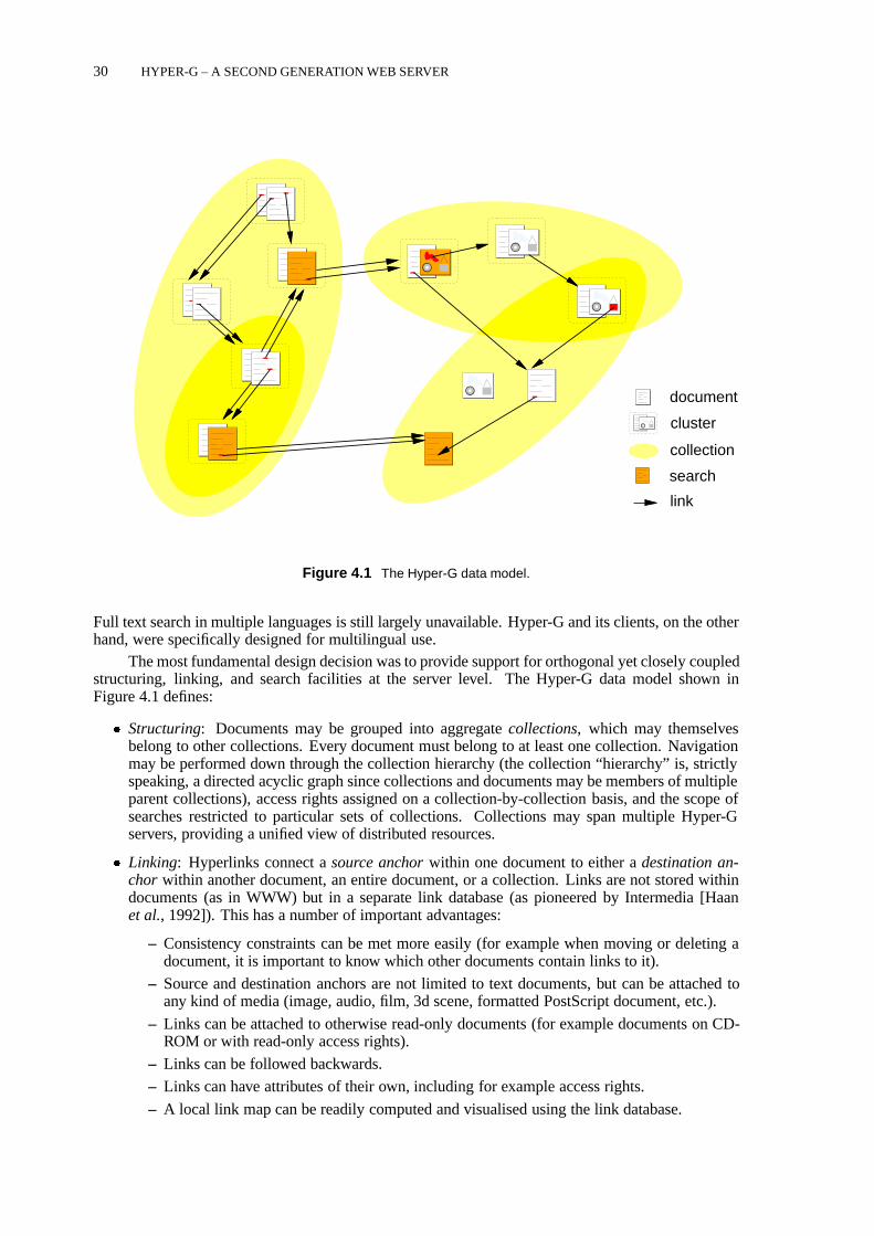
30 HYPER-G – A SECOND GENERATION WEB SERVER
document
cluster
collection
search
link
Figure 4.1 The Hyper-G data model.
Full text search in multiple languages is still largely unavailable. Hyper-G and its clients, on the otherhand, were specifically designed for multilingual use.
The most fundamental design decision was to provide support for orthogonal yet closely coupledstructuring, linking, and search facilities at the server level. The Hyper-G data model shown inFigure 4.1 defines:
� Structuring: Documents may be grouped into aggregatecollections, which may themselvesbelong to other collections. Every document must belong to at least one collection. Navigationmay be performed down through the collection hierarchy (the collection “hierarchy” is, strictlyspeaking, a directed acyclic graph since collections and documents may be members of multipleparent collections), access rights assigned on a collection-by-collection basis, and the scope ofsearches restricted to particular sets of collections. Collections may span multiple Hyper-Gservers, providing a unified view of distributed resources.
� Linking: Hyperlinks connect asource anchorwithin one document to either adestination an-chor within another document, an entire document, or a collection. Links are not stored withindocuments (as in WWW) but in a separate link database (as pioneered by Intermedia [Haanet al., 1992]). This has a number of important advantages:
– Consistency constraints can be met more easily (for example when moving or deleting adocument, it is important to know which other documents contain links to it).
– Source and destination anchors are not limited to text documents, but can be attached toany kind of media (image, audio, film, 3d scene, formatted PostScript document, etc.).
– Links can be attached to otherwise read-only documents (for example documents on CD-ROM or with read-only access rights).
– Links can be followed backwards.
– Links can have attributes of their own, including for example access rights.
– A local link map can be readily computed and visualised using the link database.

THE ARCHITECTURE OF HYPER-G 31
� Attribute and Content Search: Documents, collections, and links have an associated set ofattributes (author, title, keywords, etc.) which may be searched for, including boolean com-binations and term truncation. Full text (content) search facilities include vector and fuzzyboolean queries. Every document and collection is automatically indexed upon insertion intothe database – no extra indexing steps are required. The scope of a search may be focussedto one or more collections on one or more servers or may be as wide as all collections on allHyper-G servers worldwide.
Each of these three orthogonal features worksseamlesslyacross server boundaries, reducingfragmentation while at the same time promoting consistency. To achieve scalability in terms of num-ber of users, Hyper-G servers replicate and cache remote objects; updates are propagated to otherservers using an efficient, scalable flooding algorithm [Kappe, 1995c].
A special kind of collection, acluster, groups documents into logical entities. Clusters are usedboth to define multimedia aggregates (for example, a text and an associated image or video clip) whichare presented together and multilingual aggregates (for example, English and German translations ofa text, audio clip, structure diagram, or any combination of these).
Other design features supported by Hyper-G and include:
� Anonymous and identified user identification modes.
� A hierarchical scheme of user groups and subgroups maintained by the server.
� Access rights for users and user groups on a document or collection basis.
� “Home collections”, personal information spaces for identified users (kept on the server) usedto organise personal documents and pointers to resources.
� Language preferences, applied both to document retrieval and to the user interface.
� An underlying object-oriented database, which guarantees the consistency and integrity of data(for example the updating of links when a document is moved or deleted).
4.4 The Architecture of Hyper-GFigure 4.2 shows the client-server architecture of Hyper-G. Note the interoperability of Hyper-G withGopher and WWW clients and servers. When accessed by a Gopher client, the Hyper-G server mapsthe collection hierarchy into a Gopher menu tree. A synthetic search item is generated at the footof each Gopher menu to allow searching the corresponding collection. When accessed by a WWWclient, each level of the collection hierarchy is converted to an HTML document containing a menuof links to its members. HTML text documents residing on the Hyper-G server have their links andinline images merged in at the correct position on-the-fly. Additional Hyper-G functionality such asuser identification, language preference selection, and searching are implemented via HTML formsand are accessible by buttons at any time. The exact layout and appearance of the pages is highlyconfigurable, as is discussed later in Section 4.8.
The Hyper-G server stores references to resources on remote Gopher and WWW servers asobjects of type Remote, whereby attributes of the object specify the remote resource’s host, port,access protocol, and so forth. This allows the seamless incorporation of information on remote non-Hyper-G servers. Gopher menus are transformed into Hyper-G collections. Interoperability withZ39.50 and ftp clients and servers is planned.
Unlike Gopher or WWW clients which connect to many servers during a typical session,Hyper-G clients talk to a single Hyper-G server for the entire session, typically local to the user’sorganisation. Should information from a remote server be needed, the local server acts as a proxy, i.e.it fetches the object and passes it on to the client. This approach has the following advantages:
� Remote information can be cached in the local server for all local users.

32 HYPER-G – A SECOND GENERATION WEB SERVER
Legend: Client plannedServer
Hyper−G Server
Full TextServer
Gopher
Z39.50
FTP
Hyper−G
DocumentServer
Hyper−G
ServerObject
WWW
Gopher
WWWUser
User / AuthorHG−CSP
HTTP
Gopher
Figure 4.2 The client-server architecture of Hyper-G.
Command Purpose
GETCHILDREN get member IDs of given collection
GETOBJECTBYQUERY get object IDs matching given query
GETANCHORS get anchor IDs attached to given doc
GETOBJECT get object record with given ID
GETANDLOCK get object record and lock
CHANGEOBJECT modify object attributes
UNLOCK release lock on given object
PIPEDOCUMENT retrieve document on given port
INSERTOBJECT insert new document, collection, or link
DELETEOBJECT delete object with given ID
COMMAND status, who, message, etc.
Table 4.1 Some of the commands available in HG-CSP, Hyper-G’s client-server protocol.
� User accounts and access rights have only to be maintained on the local server (the user has toidentify to one server only).
� Statistics and user profile information can be gathered on a per-session basis.
Hyper-G clients and servers communicate using the Hyper-G Client/Server Protocol (HG-CSP)[Kappe and Pani, 1994]. A Hyper-G client opens a TCP connection to a Hyper-G server using theassigned port number 418 by default. Following protocol version and format (binary or ascii, with or

THE HYPER-G SERVER 33
hgserver
dbserverftserver dcserver
wwwmaster gophgate snmpagent
IndexObjects Local Cached
DocsDocs
Clients
Hyper−G WWW Gopher Net Mgr.
HTTP Gopher SNMPHG−CSP
418
80 70 161418
to remoteservers
*
* *
* : 1 + (# current sessions) instances
HG−CSP
to remoteservers
Protocolconversionlayer
Databaselayer
Sessionlayer
Full text
Figure 4.3 The architecture of the Hyper-G server.
without compression) negotiation, messages are exchanged using semantics similar to remote proce-dure calls (RPCs). Table 4.1 lists some of the commands available in HG-CSP. Control informationis sent via port 418, documents are usually sent through separate (parallel) channels.
4.5 The Hyper-G Server
The Hyper-G server comprises many component modules in three layers of functionality, as shown inFigure 4.3 (for a fuller description, the reader is referred to [Maurer, 1996]). The protocol conversionlayer transforms other protocols into Hyper-G’s HG-CSP, so that lower layers only need to handleone protocol. In addition to the HTTP, Gopher, and SNMP gateways shown in the figure, work isunderway on FTP and Z39.50 gateways. The session layer parallelises client requests and maintainsstate information.
The database layer provides low-level database functionality. It consists of three components:a document manager (dcserver ), an object manager (dbserver ), and a full text inverted index(ftserver ). Hyperlink, collection, and document metadata are stored as objects by the objectmanager. Hyperlinks themselves are realised internally as relations between objects, as is collectionmembership. Hence, the object manager can be thought of as a cross between an object-oriented anda relational database.
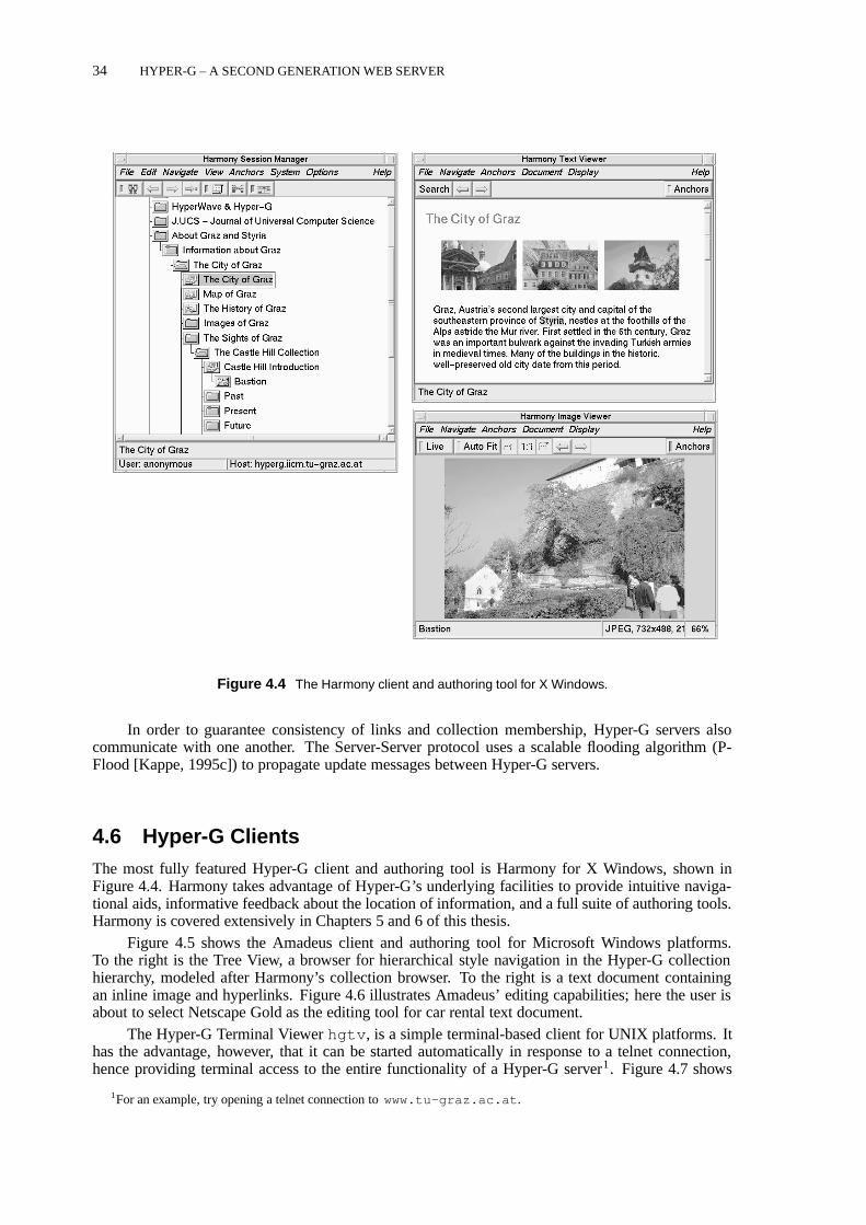
34 HYPER-G – A SECOND GENERATION WEB SERVER
Figure 4.4 The Harmony client and authoring tool for X Windows.
In order to guarantee consistency of links and collection membership, Hyper-G servers alsocommunicate with one another. The Server-Server protocol uses a scalable flooding algorithm (P-Flood [Kappe, 1995c]) to propagate update messages between Hyper-G servers.
4.6 Hyper-G ClientsThe most fully featured Hyper-G client and authoring tool is Harmony for X Windows, shown inFigure 4.4. Harmony takes advantage of Hyper-G’s underlying facilities to provide intuitive naviga-tional aids, informative feedback about the location of information, and a full suite of authoring tools.Harmony is covered extensively in Chapters 5 and 6 of this thesis.
Figure 4.5 shows the Amadeus client and authoring tool for Microsoft Windows platforms.To the right is the Tree View, a browser for hierarchical style navigation in the Hyper-G collectionhierarchy, modeled after Harmony’s collection browser. To the right is a text document containingan inline image and hyperlinks. Figure 4.6 illustrates Amadeus’ editing capabilities; here the user isabout to select Netscape Gold as the editing tool for car rental text document.
The Hyper-G Terminal Viewerhgtv , is a simple terminal-based client for UNIX platforms. Ithas the advantage, however, that it can be started automatically in response to a telnet connection,hence providing terminal access to the entire functionality of a Hyper-G server1. Figure 4.7 shows
1For an example, try opening a telnet connection towww.tu-graz.ac.at .

HYPER-G CLIENTS 35
Figure 4.5 The Amadeus client and authoring tool for Microsoft Windows.
Figure 4.6 Editing a HTML text document through Amadeus.

36 HYPER-G – A SECOND GENERATION WEB SERVER
Figure 4.7 The Hyper-G Terminal Viewer hgtv . A simple terminal-based Hyper-G client which can be usedfor example across a telnet connection. Here a Hyper-G collection is being displayed.
Figure 4.8 A text document displayed by hgtv . Note that hyperlinks are followed by typing numbers, sincesimple terminals do not support mouse clicking.

HYPER-G TOOLS AND UTILITIES 37
Figure 4.9 Easy, Hyper-G’s public terminal viewer, designed with large interface buttons for touch-screen use.
hgtv displaying one level of a Hyper-G collection hierarchy. Figure 4.8 shows a text document. Notethat since simple terminals do not support mouse clicking, links are activated by typing the numberof the link.
Another kind of Hyper-G client is Easy, the Hyper-G public terminal viewer, shown in Fig-ure 4.9. Running on Microsoft Windows platforms, Easy implements an interface designed for useby the general public at information kiosks or terminals with a touch-screen interface. It interpretslayout and synchronisation attributes and has a scripting language called SyncScript.
4.7 Hyper-G Tools and Utilities
Server administrators have a wide range of tools available to insert, maintain, and manipulate theinformation content of a Hyper-G server. Utility programs, converters, and perl scripts are avail-able to insert pre-existing data in a variety of formats. Table 4.2 gives an overview of some ofthese tools. HIF, the Hyper-G Interchange Format [Kappe, 1995a], is a clear text format used toencode entire Hyper-G collections, including subcollections, documents, links, and their metadata.Thehifexport andhifimport utilities are used to archive and transport entire collections.
loadwww is a tool to “roll over” a WWW server tree into a Hyper-G collection tree. Directoriesare mapped to Hyper-G collections, documents are uploaded, and links are entered into Hyper-G’slink database. Most importantly, original URLs remain valid, assuming that the host name remainsthe same.
A standalone Hyper-G server, called the “local database” implements a subset of Hyper-G serverfunctionality. It is intended for offline reading and authoring. For example, a local database containinga presentation, a catalogue, or conference proceedings can be put onto a CD-ROM for distribution.

38 HYPER-G – A SECOND GENERATION WEB SERVER
Tool Purpose
hginfo output information about objects
hgmodify modify attributes of objects
hginscoll insert new collection
hginsdoc/hginstext insert new document
hggetdata retrieve document
hgdelobj delete object
hgerase recursively delete subtree
hifexport export entire collection (HIF format)
hifimport import entire collection (HIF format)
loadwww load WWW directory tree into Hyper-G server
loadgopher load Gopher directory tree into Hyper-G server
hgw3stat statistics generator
hgbackup backup entire server
hgrestore restore entire server from backup
Table 4.2 Some of the low-level tools and utility scripts available to Hyper-G server administrators.
4.8 Serving to the Web with Hyper-GAlthough Hyper-G can be considered a complete Internet information system in its own right, itsprimary use is as a sophisticated Web authoring, serving, and collaborative environment. In thissection, we will discuss how a Hyper-G server presents itself to standard Web browsers such asNetscape, Mosaic, or Internet Explorer.
Information on a Hyper-G server is usually structured first into (overlapping) collections andsubcollections; both collections and documents may bere-usedby virtue of their membership ofmultiple collections. Hyperlinks are used for cross-references, orthogonal to the collection structure.Most Internet browsers today speak multiple protocols, usually at least HTTP, Gopher, and FTP. TheHyper-G server is a multi-protocol server. It responds to access requests with an appropriate repre-sentation of the requested information, preserving as much as possible of the rich functionality ofHyper-G in the process. When accessed using Gopher protocol, the Hyper-G server presents its col-lection hierarchy as a Gopher menu tree (hyperlinks cannot be represented in Gopher). A syntheticsearch item is generated at the foot of each Gopher menu to allow searching the corresponding col-lection. When accessed using HTTP, each level of the collection hierarchy is converted to an HTMLdocument containing a menu of links to its members. Hyperlinks are merged into HTML text docu-ments and VRML 3d models on-the-fly at the appropriate places. Additional Hyper-G functionalitysuch as user identification, language preference selection, and searching is implemented via HTMLforms which are accessible at any time. Java applets will soon supplement forms-based access toHyper-G functionality.
Figure 4.10 shows the welcome page of the IICM Information Server through the eyes ofNetscape. Access to Hyper-G functionality and contextual and meta information are wrapped aroundthe document proper. Each HTML page passed to the client typically comprises four logical compo-nent areas:
� TheMenu Barat the top of the page has four buttons, Options, Search, Help, and Home, respec-tively.
� TheText Areadisplays a text document (and also the head of a collection, if present). Imageswithin a cluster are displayed as inline images.

SERVING TO THE WEB WITH HYPER-G 39
Figure 4.10 The IICM welcome page, seen through the eyes of Netscape. The welcome document is a fullcollection head, containing embedded links to its siblings and children, hence the collection area is not present(the middle of the page has been clipped out for a better overview).
� TheCollection Areais present only for collections without a Full Collection Head and displayslinks to the other members (documents, clusters, and subcollections) of the collection.
� TheAttributes Areaat the bottom of the page provides meta-information about the document orcollection, such as author, creation time, access rights, etc. Often, a list of parent collections isalso provided here.
Note that the presence and appearance of these areas is highly configurable in the Hyper-Gserver’s WWWgateway,wavemaster , using a kind of programmable meta-HTML language calledPLACE [PLACE, 1996]2. Hence the look of Web servers running Hyper-G can vary widely fromserver to server depending on their administrator’s policy and preferences. Figures 4.14 and 4.15show, for example, the European Space Agency’s Earth Observation Guide and Directory Service.
The Hyper-G Search panel shown in Figure 4.11 is the interface to Hyper-G’s powerful attributeand content search facilities. Searches may be restricted in scope to the current collection (and its
2The older gateway,wwwmaster , was also configurable, but not to the same extent aswavemaster is.

40 HYPER-G – A SECOND GENERATION WEB SERVER
Figure 4.11 The Hyper-G search panel.
subcollections), or may span the whole local server. Here the user is searching for information onHyper-G’s HIF interchange format, in both the title and keyword attribute fields and the textual con-tent of documents. Figure 4.12 shows the list of matching objects returned by the server. Furtherfunctionality is embodied by the Hyper-G Options panel, another HTML form, where users can seewho else is online, change their language preference, and so forth.
The Hyper-G server stores a reference to a remote (non-Hyper-G) resource, such as a documentaccessible by HTTP, Gopher, or FTP, as a Remote Object of the appropriate type. The object’sattributes contain the host, port, and location of the resource. This allows the seamless incorporationof information on remote, non-Hyper-G servers.
Arbitrary Java applets (complied byte code) may be uploaded and stored on a Hyper-G serverin the same way as other documents, and have a full set of attribute metadata. HTML documentsreference them by name or ID in the applet tag.
The standard way of bolting extensions to WWW servers is the Common Gateway Interface(CGI). Put simply, CGI is a naming convention for a set of environment variables which pass infor-mation and parameters from the calling URL into a program started at the server. The CGI programitself can be written in any programming language, although often a scripting language such as Perl isused. The CGI program generates its output as a HTML page, which is returned back to the request-

APPLICATIONS OF HYPER-G 41
Figure 4.12 Hyper-G search results. Full text matches are ranked in decreasing order of relevance.
ing client. Among other things, CGI programs are used to parse the results of a HTML form and toprovide back-end access to external databases. The Hyper-G server provides full support for CGI.
One of the problems with CGI, however, is that a new process is typically started for eachand every CGI call. Particularly when integrating external database packages, this entails substantialoverhead. For this reason, the Hyper-G server has a special back-end interface called the Hyper-GGateway Interface (HGI) [Reisinger and Faschingbauer, 1996], shown schematically in Figure 4.13.HGI allows the server to hold a persistent connection to an external source. A Perl 5 module isavailable for writing arbitrary HGI gateways and a sample, HGI-conformant SQL gateway is supplied.
4.9 Applications of Hyper-G
The structuring and ease of maintenance oflarge information bases is one of the major strengths ofHyper-G. The IICM Information Serverwww.iicm.edu currently (September 1996) holds about213 000 documents, organised in almost 40 000 clusters and collections, with 290 000 links, and 905users organised into 26 user groups – and runs on a PC under Linux. The information resources in-

42 HYPER-G – A SECOND GENERATION WEB SERVER
The Hyper−G Gateway Interface
hgserver dcserver
HGI gateway
WWW ClientHG Client
wavemaster
ExternalSource
HTTP: GET, POST
HG−CSP
HG−CSP
HTTP 1.1: OPTIONS, GET, POST
Hyper−G Server
Figure 4.13 The Hyper-G Gateway Interface (HGI).
clude online documentation about Hyper-G and HyperWave, information about Graz and Austria, andthe complete Meyers Lexikon (a German-language encyclopedia). Graz University of Technology’sHyper-G Information Server contains personnel and course information as well as the complete ACMSIGGRAPH and HCI bibliographies (fully searchable).
The European Space Agency (ESA) uses Hyper-G to organise and publish its earth observationdata. Figure 4.14 shows the welcome page of the ESA Earth Observation Guide and Directory Service(GDS), which currently comprises some 88 000 documents. The look and feel of the Hyper-G serveris highly customisable – note the replacement of the standard Hyper-G icons by customised ESAversions. The Museum of New Zealand and numerous other companies and institutions have adoptedHyper-G for their own information systems. The German Mathematics Association (DMV) has setup a Hyper-G-based information system spanning several German universities and colleges.
Hyper-G also is being used as the basis for major new electronic publishing ventures. The Jour-nal of Universal Computer Science (J.UCS), supported by Springer Verlag, is the first high-quality,fully-refereed, fully-citable scientific journal to depend primarily on Internet distribution [Maurer andSchmaranz, 1994]. J.UCS went online in January 1995, and has appeared monthly since. One of thelargest Austrian daily newspapers, the Kleine Zeitung, uses Hyper-G for its online edition [Medien-haus Styria, 1996].
4.10 Further Reading
The most complete guide to Hyper-G and HyperWave is the recent bookHyperWave: The NextGeneration Web Solution[Maurer, 1996]. A more tutorial-like treatment is given inHyperWave:The New Generation Internet Information System Based on Hyper-G Technology[Dalitz and Heyer,1996]. Good overview articles have also appeared in BYTE [Flohr, 1995], New Media [Sengstack,1996], and Computer Shopper [Aubrey, 1996] magazines.

FURTHER READING 43
Figure 4.14 The European Space Agency’s Earth Observation Guide and Directory Service (here the top halfof the welcome page).
Further information about Hyper-G is available online at the IICM Information Server un-der http://www.iicm.edu/hyperg . Updated slides from my ACM Hypertext’96 course onHyper-G [Andrews, 1996c] are available online athttp://www.iicm.edu/hgcourse . Thesoftware itself is available by anonymous ftp fromftp://ftp.iicm.edu/pub/Hyper-G .

44 HYPER-G – A SECOND GENERATION WEB SERVER
Figure 4.15 The European Space Agency’s Earth Observation Guide and Directory Service (here the bottomhalf of the welcome page). Note the collection area, listing the members of the current collection.

5 Browsing Cyberspace with Harmony
This chapter presents the browsing and navigational features of the Harmony client forHyper-G. It is based on material first published in Chapter 15 of HyperWave: The NextGeneration Web Solution, Addison-Wesley, May 1996 [Andrews, 1996f].
5.1 Designing a Graphical Hypermedia Client
In the summer of 1991, when the World-Wide Web was still unknown, and only a simple terminalclient hgtv existed for Hyper-G, I assumed responsibility at the IICM for designing, and leadinga team to implement, a new graphical hypermedia client for Hyper-G, later to became known asHarmony. My intention was to create a powerful graphical browsing and authoring tool, which wouldbring the sophisticated information structuring and management concepts of Hyper-G to the reachof end users, both locallyand across the Internet. This chapter deals with Harmony’s browsing andnavigational facilities. Chapter 6 describes Harmony’s powerful editing, management, and structuringtools.
The technical merit of Harmony lies in itsintegratedsuite of tools and in theinterplaybetweenthem. As a member of the audience at my CHI’95 talk [Andrewset al., 1995b] told me after the talk:
“One of the most impressive things about Harmony is that it all works!”
Perhaps the most important scientific contribution of Harmony islocation feedback, alleviatingthe “lost in hyperspace” problem by helping users retain a sense of position in large hypermedia in-formation spaces. Location feedback is the term I coined to describe the synchronised, correlated,navigational views which Harmony provides. Selecting or activating an object (document or collec-tion) in any of the local map, search result list, history browser, or by link following,automaticallyopens up the path(s) to that object in the collection structure, thus providing immediate contextualfeedback. As Jakob Nielsen states inMultimedia and Hypertext: The Internet and Beyond[Nielsen,1995]:
“This feature of Harmony is a powerful instrument in the fight against disorientation be-cause users can orient themselves with reference to a fixed structural framework.”
Location feedback is discussed in Sections 5.5 and 5.6. A further important contribution isHarmony’s support for multilingual information collections, both in terms of information content anduser interface. This is described in Section 5.11 at the end of this chapter.
Since Hyper-G stores hyperlinks in a separate link database, rather than embedded within do-cuments, documents of any media type can function as the source of links. From the beginning,Harmony was intended to take advantage of this feature, by providing viewers and interactive linkcreation facilities for at least six different types of media: text, images, video, audio, page descrip-tion files (PostScript), and 3d models. In particular, Harmony’s display and linking facilities for 3dmodels, as described in Chapter 7, pre-date equivalent facilities in VRML (Virtual Reality ModelingLanguage) [Pesce, 1995] by more than two years [Andrews, 1992].
The rich structure and extensive metadata made available by the Hyper-G server appeared tome to be the perfect infrastructure upon which to build visualisations of the information space, afield which has since become known as “information visualisation”. Harmony’s Local Map andInformation Landscape are the results of my research in this direction and are described in detail inChapter 8.
45

46 BROWSING CYBERSPACE WITH HARMONY
control
documents
SessionManager
HarmonyHyper−GServer
Text
Image
Film
Audio
3D
PostScript
External
HG−CSP
HarmonyDVP
stdin
port 418
Figure 5.1 The architecture of Harmony client and authoring tool for Hyper-G.
5.2 The Architecture of Harmony
Harmony was designed as a multi-process application, as illustrated in Figure 5.1. The Session Man-ager is the primary process; it communicates with the Hyper-G server, provides navigational facilitiesand coordinates all other activities. The Session Manager starts secondary processes, document view-ers, of the appropriate type, to display documents as necessary. Native Harmony document viewerscommunicate with the Session Manager using Harmony’s own protocol, the Harmony DocumentViewer Protocol (DVP), which defines various browsing, editing, and link functions. There cur-rently exist native Harmony document viewers for text, images, MPEG films, audio, 3d models, andPostScript. Figure 5.2 shows an example screen shot of the Harmony client.
Harmony may be configured to run external programs in place of any native viewer and also forunsupported document types (the document is piped to the standard input of the external program).However, since external programs do not “speak” Harmony’s protocol, they are generally unable tosupport link activation and editing. A Harmony API is also available for external tools which makeuse of Harmony’s functionality and state. One such tool is a generic edit facility, which can beconfigured to start an external editor for any document type.
The Harmony Session Manager connects to the Hyper-G server on Hyper-G’s assigned portnumber 418. This connection is kept open for the duration of the session and is the channel throughwhich control information (all communication except actual documents) passes in both directions.Documents themselves are not sent from the server via the Session Manager to a document viewer, butdirectly from server to document viewer. In the original design, the document cache in the Hyper-Gserver opened a connection back to the viewer, using a port dynamically assigned by the viewer.However, since certain network configurations (for example, machines behind a firewall or using anemulated SLIP connection) do not allow the server to connect back to the client on an arbitrary port,this connection procedure has been turned around so that the viewer connects to the server.
Harmony is written in C++ [Stroustrup, 1991]. Back in 1991, I chose to use the InterViews[Linton et al., 1989] user interface toolkit from Stanford, primarily because it was freely availablein source code with no licence restrictions. Over time, the original InterViews library has been soextensively modified, extended, and bug-fixed that we call the version used in Harmony “IICMViews”to distinguish the two!
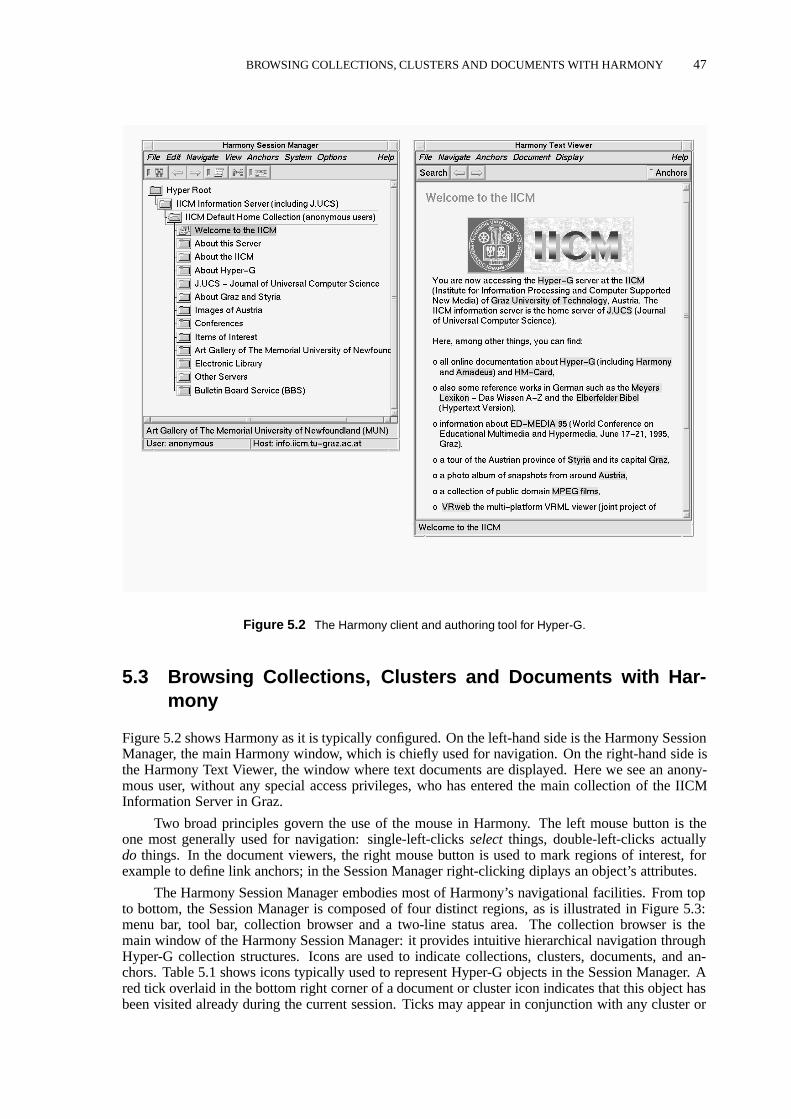
BROWSING COLLECTIONS, CLUSTERS AND DOCUMENTS WITH HARMONY 47
Figure 5.2 The Harmony client and authoring tool for Hyper-G.
5.3 Browsing Collections, Clusters and Documents with Har-mony
Figure 5.2 shows Harmony as it is typically configured. On the left-hand side is the Harmony SessionManager, the main Harmony window, which is chiefly used for navigation. On the right-hand side isthe Harmony Text Viewer, the window where text documents are displayed. Here we see an anony-mous user, without any special access privileges, who has entered the main collection of the IICMInformation Server in Graz.
Two broad principles govern the use of the mouse in Harmony. The left mouse button is theone most generally used for navigation: single-left-clicksselectthings, double-left-clicks actuallydo things. In the document viewers, the right mouse button is used to mark regions of interest, forexample to define link anchors; in the Session Manager right-clicking diplays an object’s attributes.
The Harmony Session Manager embodies most of Harmony’s navigational facilities. From topto bottom, the Session Manager is composed of four distinct regions, as is illustrated in Figure 5.3:menu bar, tool bar, collection browser and a two-line status area. The collection browser is themain window of the Harmony Session Manager: it provides intuitive hierarchical navigation throughHyper-G collection structures. Icons are used to indicate collections, clusters, documents, and an-chors. Table 5.1 shows icons typically used to represent Hyper-G objects in the Session Manager. Ared tick overlaid in the bottom right corner of a document or cluster icon indicates that this object hasbeen visited already during the current session. Ticks may appear in conjunction with any cluster or

48 BROWSING CYBERSPACE WITH HARMONY
Figure 5.3 The Harmony Session Manager.
document icon, not only text documents. A green arrow overlaid in the bottom left of a documenticon indicates an anchor object (either source or destination) in a document of the specified type. An-chor objects are not currently represented in the collection browser; they can, however, be assignedsearchable attributes and thus appear in the search result list.
Hierarchical navigation through Hyper-G collection structures is extremely intuitive, since usersare presented with a limited set of visible choices at each level. One popular way of finding informa-tion on a Hyper-G server is to start at the top collection and open up sub-collections until the desiredinformation is found.
Collections may be opened and closed and documents retrieved in a number of alternative ways:by double-left-clicking, by selecting and using menu commands, and via extensive keyboard short-cuts. Thecurrently selected object(collection, cluster, or document) is framed in a thin box. Objectsmay be selected by single-left-clicking with the mouse, or by using the arrow keys to move the currentselection focus. The currently selected object is the target of a number of commands and operations.To provide visual feedback, the most recently displayed document or cluster is underlaid with a solidbar (it is not necessarily the same object as the current selection).
Navigational Functions
The Harmony Session Manager’s navigational functions include:
� OpenThe Open operation lists a collection’s members in the collection browser, displays the collec-tion head (if present) and moves the selection focus to the first object in the collection. Openinga cluster displays the cluster (in the appropriate document viewers), but does not list its members

BROWSING COLLECTIONS, CLUSTERS AND DOCUMENTS WITH HARMONY 49
Icon Meaning Icon Meaning
Collection (closed) Image document
Collection (open) Film document
Cluster Audio document
Cluster (visited) PostScript document
Text document Scene document
Text document (visited) Generic document
Anchor in text document Telnet session
Anchor in text (visited)
Table 5.1 Typical icons used for Hyper-G objects in Harmony.
in the collection browser. Cluster members whose PresentationHints attribute contains the wordHidden are not displayed (this is useful for keeping inline images and textures in the same clusteras the documents in which they are used, without have them also displayed in separate viewers).Clusters may contain a mix of language-dependent and language-independent documents. Inthis case the rules for presentation are:
(1) All language-independent members of the cluster are visualised. Language-independentobjects are those having multiple Title attributes in different languages.
(2) From the remaining language-dependent members of the cluster, one member of eachdocument type is chosen (based on the user’s language preferences) and visualised.
Opening a document simply displays the document.
� CloseWhen a collection or cluster is closed, its members are no longer listed in the collection browser(they are not removed from the document viewers, however). The Session Manager’s Closeoperation has no effect on document objects.
� ChildrenThe children (members) of the currently selected collection or cluster can be explicitly listed(or hidden) in the collection browser with the Children command. No documents (not even acollection head) are displayed by the Children command.
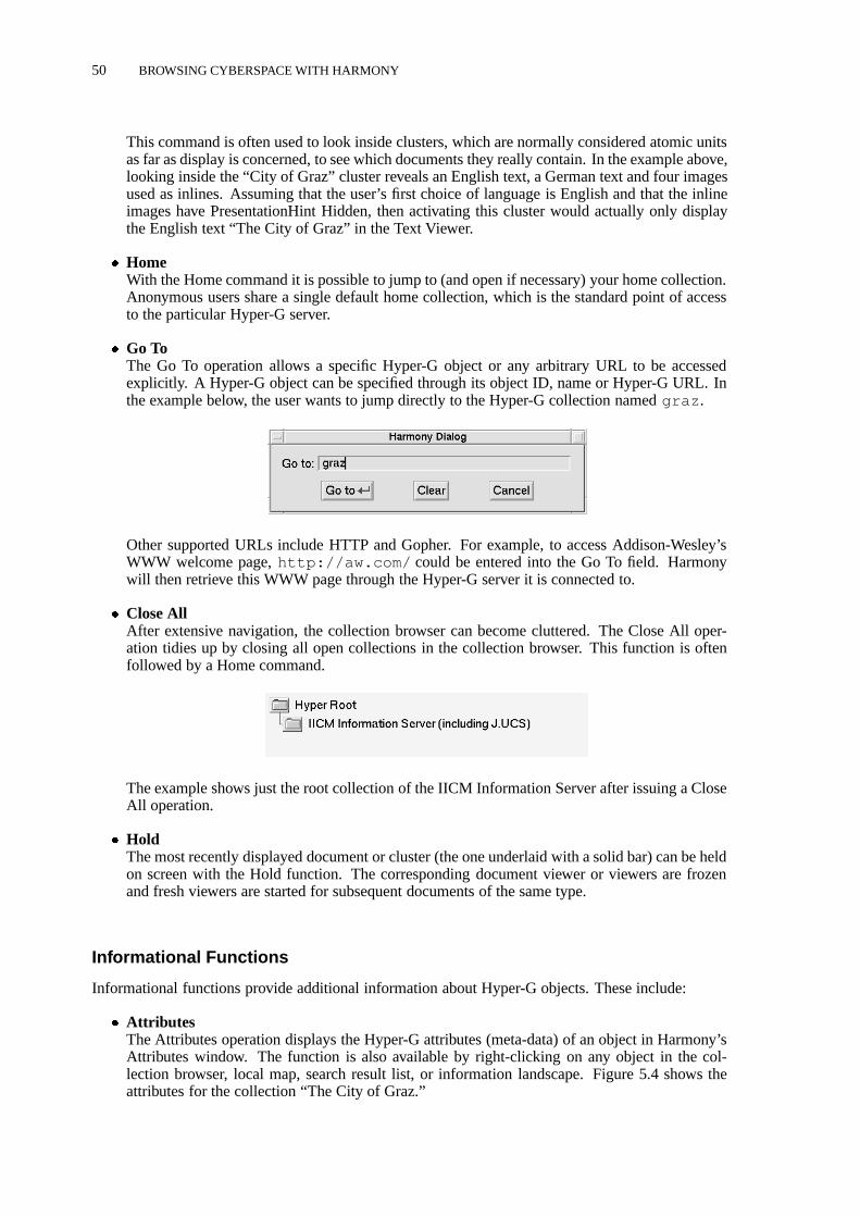
50 BROWSING CYBERSPACE WITH HARMONY
This command is often used to look inside clusters, which are normally considered atomic unitsas far as display is concerned, to see which documents they really contain. In the example above,looking inside the “City of Graz” cluster reveals an English text, a German text and four imagesused as inlines. Assuming that the user’s first choice of language is English and that the inlineimages have PresentationHint Hidden, then activating this cluster would actually only displaythe English text “The City of Graz” in the Text Viewer.
� HomeWith the Home command it is possible to jump to (and open if necessary) your home collection.Anonymous users share a single default home collection, which is the standard point of accessto the particular Hyper-G server.
� Go ToThe Go To operation allows a specific Hyper-G object or any arbitrary URL to be accessedexplicitly. A Hyper-G object can be specified through its object ID, name or Hyper-G URL. Inthe example below, the user wants to jump directly to the Hyper-G collection namedgraz .
Other supported URLs include HTTP and Gopher. For example, to access Addison-Wesley’sWWW welcome page,http://aw.com/ could be entered into the Go To field. Harmonywill then retrieve this WWW page through the Hyper-G server it is connected to.
� Close AllAfter extensive navigation, the collection browser can become cluttered. The Close All oper-ation tidies up by closing all open collections in the collection browser. This function is oftenfollowed by a Home command.
The example shows just the root collection of the IICM Information Server after issuing a CloseAll operation.
� HoldThe most recently displayed document or cluster (the one underlaid with a solid bar) can be heldon screen with the Hold function. The corresponding document viewer or viewers are frozenand fresh viewers are started for subsequent documents of the same type.
Informational Functions
Informational functions provide additional information about Hyper-G objects. These include:
� AttributesThe Attributes operation displays the Hyper-G attributes (meta-data) of an object in Harmony’sAttributes window. The function is also available by right-clicking on any object in the col-lection browser, local map, search result list, or information landscape. Figure 5.4 shows theattributes for the collection “The City of Graz.”

BROWSING COLLECTIONS, CLUSTERS AND DOCUMENTS WITH HARMONY 51
Figure 5.4 The Harmony Attributes window.
� Show HostShow Host displays the host on which the currently selected Hyper-G object resides. This isuseful for determining whether an object is located on the local Hyper-G server (the one to whichHarmony is connected), or on a remote Hyper-G server. Note that a host’s name corresponds toits Internet address, which is incorporated as the first four bytes of the GOid attribute.
� Show CountShow Count turns on (or off) display of the document count for collections in the collectionbrowser.
The document count corresponds to the Subdocs attribute of a collection and gives the numberof documents contained in the collection and all of its sub-collections (recursively), which arelocated on the local Hyper-G server. Member documents residing on remote servers arenotincluded in the count.
The Toolbar
The Harmony Session Manager toolbar provides direct access to the most frequently used Har-mony functions. The Back and Forward buttons are disabled (grayed out) if the end of the history listin the corresponding direction has been reached. Table 5.2 explains the icons typically visible in theSession Manager’s toolbar.

52 BROWSING CYBERSPACE WITH HARMONY
Icon Name Meaning
Search Map/unmap Search window
Back Move back in history list
Forward Move forward in history list
History Map/unmap History window
Local Map Map/unmap Local Map window
Landscape Map/unmap Landscape window
Table 5.2 Typical icons used in the Harmony Session Manager’s toolbar.
Keyboard Support
The Harmony Session Manager has extensive keyboard support. The up arrow (") and down arrow(#) keys move the current selection in the collection browser up and down as you would expect. Theleft arrow ( ) key jumps the current selection back one level in the collection hierarchy to the currentselection’s parent. TheReturn key opens the current selection if it is a collection, or retrieves anddisplays the current selection if it is a cluster or document. The right arrow (!) and the plus (+) keysdo the same as theReturn key, except that they also advance the selection into any collection whichis opened. The minus (�) key closes the current selection if it is a collection or cluster. ThePageUp andPage Down keys scroll the collection browser display by one page,Ctrl-l centers thedisplay around the current selection,Ctrl- " andCtrl- # scroll the display by one line up or down.Table 5.3 gives a list of typical keyboard shortcuts in the Harmony Session Manager.
5.4 Harmony’s Document Viewers and Hyperlink NavigationHarmony has native document viewers for six kinds of media: text, image, MPEG films, audio,PostScript, and 3d scenes. Many of the viewers recognise several document encoding formats. Har-mony can also be configured to start external viewers for other document types, but external viewersdo not generally possess the hyperlink facilities of Harmony’s native document viewers.
Associative browsing through hyperlinks is the second main means of navigation in Hyper-G.Users often explore the information space by associative link browsing, either having started outdirectly from an introductory document with further links, or after having found an interesting docu-ment by hierarchical navigation or by searching and beginning from there. Hyperlinks in Hyper-Glead from part of one document to (part of) another associated document or to an associated clusteror collection. The source of a link is typically represented visually as a “clickable” hot region of adocument. Since any kind of media may contain hyperlinks in Hyper-G, Harmony provides hyperlinkfacilities in each of its six document viewers.
In addition to a button to turn link anchor display on and off, all native Harmony document view-ers share a number of common navigational facilities such as Hold (to hold the current document onscreen), Attributes (to show the attributes of the current document), shortcuts to history functionalitysuch as Back and Forward, and shortcuts to Local Map functionality such as References, Annotations,and Parents.

HARMONY’S DOCUMENT VIEWERS AND HYPERLINK NAVIGATION 53
Key Function
x Exit program (confirmation dialogue)
Ctrl -x Exit program (no confirmation dialogue)
Tab Next focus (used in dialogues and search)
Return Open/close collection, display document
+! Open collection, goto first child, display document
� Close collection/cluster
c Show/hide children of collection/cluster, do not displaycollection head
Space , n Next. Display next/current unvisited object
p Previous. Display current/previous unvisited object
Ctrl-c Close all collections, open path to root of local server
Ctrl-l Recenter currently selected object
", # Select previous/next object
Ctrl- ", Ctrl- # Scroll one line up/down
Shift- ", Shift- # Select previous/next object, including objects with notitle
Page Down, Ctrl-v Scroll one page down
Page Up, Alt-v Scroll one page up
Select parent collection
a Show object attributes
e Edit object attributes
i Map identify dialogue
s Map/unmap search dialogue
b One step back in history
f One step forward in history
l Generate local map
L Unmap local map
R Show references
A Show annotations
P Show parents
Ctrl-a Annotate object
h Map/unmap history window
H Goto home collection
g Goto dialogue
Ctrl-d , Delete Remove object from collection
Ctrl-i , Insert Insert object into collection
Ctrl-s Display system status
M Move object
C Copy object
Alt-s Display server where the object resides
Table 5.3 Keyboard support in the Harmony Session Manager.

54 BROWSING CYBERSPACE WITH HARMONY
Figure 5.5 The Harmony Text Viewer displaying a HTML document.
The Harmony Text Viewer
The Harmony Text Viewer displays documents in both HTML [Berners-Lee and Conolly, 1993; Mus-ciano and Kennedy, 1996] and Hyper-G’s original, but now obsolete, HTF [Kappe, 1995b] format.Inline images in GIF, JPEG, TIFF, and PNG formats are supported. Figure 5.5 shows the Text Viewerdisplaying a text concerning the Graz Arsenal. In 1995 and 1996, the Harmony Text Viewer wascompletely redesigned and re-implemented by a team lead by Mansuet Gaisbauer, to better supportHTML 3.x constructs such as tables and free-flowing text around images.
In the Text Viewer, a hyperlink is represented either by underlining, colour coding, or as asolid area underlying the extent of the source anchor, such as “Graz” or “Provincial Parliament” inFigure 5.5. A common technique is to create an itemised list in the text document and link membersof the list to associated documents, as has been done for the main exhibits in the Arsenal. Anchors areselected by a single-left-click and activated by double-left-click. TheTab key can be used to cyclethrough the anchors and theReturn key to activate the currently selected anchor. In HTF texts, upto six levels of overlapping link anchors (overlapping links are possible in HTF, but not currently inHTML) are displayed as separate horizontal layers within the solid anchor area. In the example below,links emanate both from the word “Graz” and from the phrase “Graz University of Technology”:

HARMONY’S DOCUMENT VIEWERS AND HYPERLINK NAVIGATION 55
� Search in TextIt is possible to search for regular expressions within a text document. The regular expressionsyntax is similar to that of the UNIX commandsawk andegrep . For example, searching for[Aa]rsenal :
finds both capitalised and non-capitalised occurrences of the word:
The regular expression[0-9]+ matches one or more adjacent numeric digits:
finding the digits30 in the example below:
� Save AsThe current text document can be saved to your local UNIX file system, either as plain ascii textor in its original marked-up hypertext format (HTML or HTF).
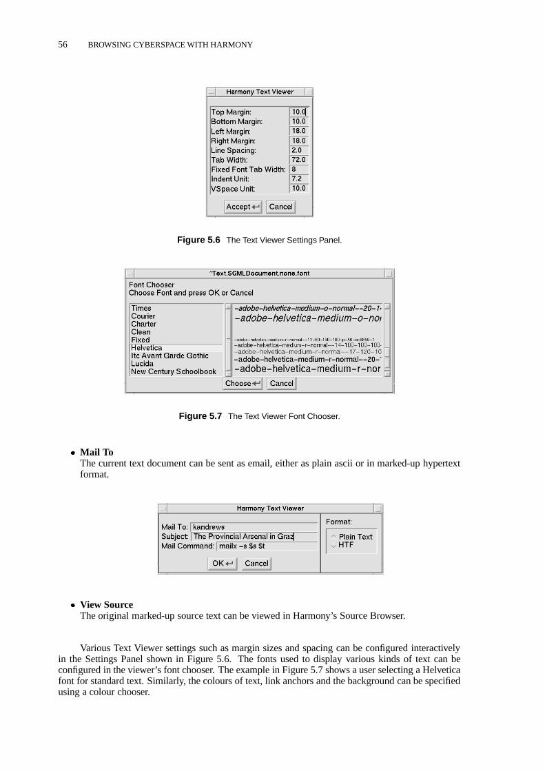
56 BROWSING CYBERSPACE WITH HARMONY
Figure 5.6 The Text Viewer Settings Panel.
Figure 5.7 The Text Viewer Font Chooser.
� Mail ToThe current text document can be sent as email, either as plain ascii or in marked-up hypertextformat.
� View SourceThe original marked-up source text can be viewed in Harmony’s Source Browser.
Various Text Viewer settings such as margin sizes and spacing can be configured interactivelyin the Settings Panel shown in Figure 5.6. The fonts used to display various kinds of text can beconfigured in the viewer’s font chooser. The example in Figure 5.7 shows a user selecting a Helveticafont for standard text. Similarly, the colours of text, link anchors and the background can be specifiedusing a colour chooser.

HARMONY’S DOCUMENT VIEWERS AND HYPERLINK NAVIGATION 57
Figure 5.8 The Harmony Image Viewer.
Figure 5.9 Links in image documents.
The Harmony Image Viewer
The Harmony Image Viewer displays images in a number of common formats, including GIF, JPEG,TIFF, and PNG. Figure 5.8 shows the Image Viewer displaying a JPEG image of the castle hill in Grazcity centre. The status line at the bottom of the viewer indicates the image’s title, format, resolution,size, and current magnification.
Link anchors in image documents may be rectangular, circular, elliptical or polygonal in shape(this applies to both source and destination anchors). The image of Graz Arsenal in Figure 5.9 hastwo source anchors: a polygonal anchor enclosing the horse armour to the left and a circular anchorenclosing the heavy cavalry armour to the right. Anchors are selected by a single-left-click andactivated by double-left-click. TheTab key can be used to cycle through the anchors and the Return

58 BROWSING CYBERSPACE WITH HARMONY
Figure 5.10 Image Viewer colour configuration.
key to activate the currently selected anchor (this is useful for overlapping link anchors). The coloursused to represent link anchors can be configured using the Colour Dialogue shown in Figure 5.10.
The Live button determines whether or not images are displayed progressively as they are re-ceived. AutoFit causes images to be scaled (larger or smaller) so that they fit the current image displayarea. Turning ShrinkOnly on will only scale images down and not enlarge them if autofitting is en-
abled. When AutoFit is disabled, the smaller (�25%), original size (100%) and larger(+33%) buttons and menu items for zooming in and zooming out become accessible.
The Harmony Film Player
The Harmony Film Player plays film clips in MPEG-1 format. Figures 5.11 and 5.12 show the FilmPlayer displaying a video clip taken from the Graz Arsenal. Analogous to the Image Viewer, thestatus line at the bottom of the Film Player indicates the film clip’s title, format, resolution, size, andcurrent magnification. VCR style control buttons are provided for playing, pausing, rewinding, andsingle-stepping through the film. The Live button determines whether or not films are played backas they are received. Loop causes the film to be played continuously. MPEG audio is not currentlysupported; if an audio stream is present, it is silently ignored.
Link anchors in films may be rectangular, circular, or elliptical in shape (this applies to bothsource and destination anchors). Their position and size are defined for specific key frames andare interpolated in between. Source anchors may be activated even during playback. The image inFigure 5.11 shows a circular source anchor around the cavalry helmet in the first part of the film. Theimage in Figure 5.12 illustrates a destination anchor covering the last segment of the clip which dealswith horse armour.
The Film Player’s Settings Panel, depicted in Figure 5.13, allows various settings to be config-ured interactively. Particularly useful are the brightness and the frame rate. By default frames aredrawn as fast as possible; the frame rate is only synchronised upon specific request. The colours usedto represent link anchors in the Film Player are configurable interactively using a Colour Dialoguesimilar to that of the Image Viewer.

HARMONY’S DOCUMENT VIEWERS AND HYPERLINK NAVIGATION 59
Figure 5.11 The Harmony Film Player.
Figure 5.12 A destination anchor extending across the second half of a film clip.
The Harmony Audio Player
The Harmony Audio Player plays audio clips. The supported audio formats depend on the underlyingplatform and on the Audio Player’s configuration. By default, the Audio Player does not look into theaudio stream itself, but simply passes it on to the client machine’s native audio play command. In this
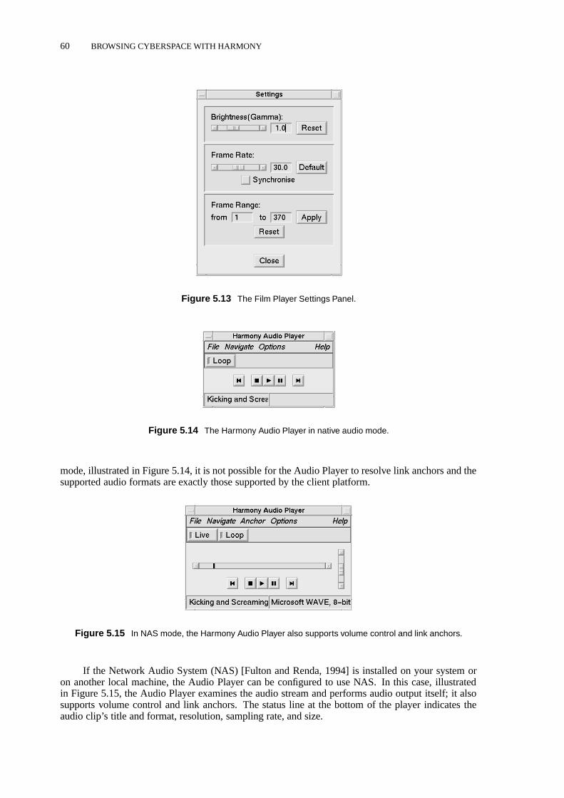
60 BROWSING CYBERSPACE WITH HARMONY
Figure 5.13 The Film Player Settings Panel.
Figure 5.14 The Harmony Audio Player in native audio mode.
mode, illustrated in Figure 5.14, it is not possible for the Audio Player to resolve link anchors and thesupported audio formats are exactly those supported by the client platform.
Figure 5.15 In NAS mode, the Harmony Audio Player also supports volume control and link anchors.
If the Network Audio System (NAS) [Fulton and Renda, 1994] is installed on your system oron another local machine, the Audio Player can be configured to use NAS. In this case, illustratedin Figure 5.15, the Audio Player examines the audio stream and performs audio output itself; it alsosupports volume control and link anchors. The status line at the bottom of the player indicates theaudio clip’s title and format, resolution, sampling rate, and size.

HARMONY’S DOCUMENT VIEWERS AND HYPERLINK NAVIGATION 61
The Harmony PostScript Viewer
Figure 5.16 The Harmony PostScript Viewer.
The Harmony PostScript Viewer displays documents described in the PostScript page descriptionlanguage. PostScript documents compressed with GNUgzip are automatically decompressed bythe viewer. GhostScript (gs ) is used to generate the individual page images (note thatgzip andgs must both be installed on your system and be in your path for the PostScript viewer to functionproperly). Figure 5.16 shows the PostScript Viewer displaying an 18-page article which appeared intheJournal of Universal Computer Science[Maurer and Schmaranz, 1994].
Link anchors in PostScript documents are rectangular areas overlaid on the page, such as the fourlinks to references later in the article in Figure 5.16. A destination anchor is highlighted, or rather
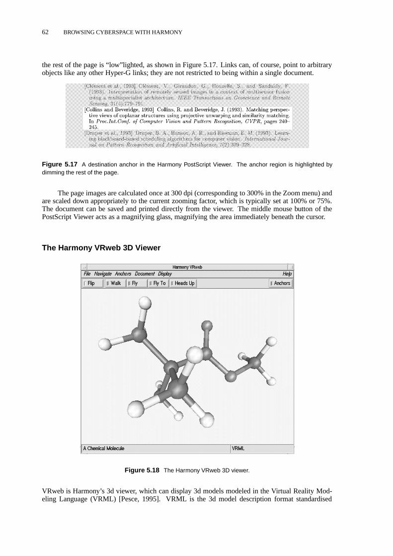
62 BROWSING CYBERSPACE WITH HARMONY
the rest of the page is “low”lighted, as shown in Figure 5.17. Links can, of course, point to arbitraryobjects like any other Hyper-G links; they are not restricted to being within a single document.
Figure 5.17 A destination anchor in the Harmony PostScript Viewer. The anchor region is highlighted bydimming the rest of the page.
The page images are calculated once at 300 dpi (corresponding to 300% in the Zoom menu) andare scaled down appropriately to the current zooming factor, which is typically set at 100% or 75%.The document can be saved and printed directly from the viewer. The middle mouse button of thePostScript Viewer acts as a magnifying glass, magnifying the area immediately beneath the cursor.
The Harmony VRweb 3D Viewer
Figure 5.18 The Harmony VRweb 3D viewer.
VRweb is Harmony’s 3d viewer, which can display 3d models modeled in the Virtual Reality Mod-eling Language (VRML) [Pesce, 1995]. VRML is the 3d model description format standardised

THE HARMONY LOCAL MAP 63
Figure 5.19 A Harmony Telnet session to HYTELNET.
by the WWW community [Bellet al., 1996a,b]. Figure 5.18 shows Harmony VRweb displaying aVRML model of a chemical molecule. Flip navigation mode, active here, enables the model itself tobe moved and rotated, without changing the user’s position. VRweb’s other four navigation modes(Walk, Fly, Fly To, and Heads Up) all involve the user moving through the model.
VRweb is described in detail in Chapter 7, so here I will concentrate on the additional function-ality provided in the Harmony version of VRweb for Hyper-G. One of the main benefits of usinga Hyper-G server is its link management. When a 3d model in VRML is uploaded onto Hyper-Gserver, its hyperlinks, inline links, and texture links are extracted and are entered into Hyper-G’s linkdatabase, in the same way as links and inline images in HTML texts. When the model is accessed, theappropriate nodes are merged back in to the VRML file. Using Harmony VRweb, links can be editedinteractively. It will also soon be possible to edit models within VRweb: not at the polygon level,but by importing and including models and by moving, rotating, and scaling existing models. Oncethis functionality is stable and released, a Hyper-G server will become a powerful system for keepingtrack of models, their components, and textures. In other systems, renaming a model file or movinga texture file to a different directory can have dire consequences, since each and every embeddedreference has to be changed to match.
Harmony Telnet Sessions
Telnet sessions can be started from within Harmony by activating a Telnet object. Figure 5.19 showsa telnet session toHYTELNET. Upon activation, the Harmony Session Manager opens a new X ter-minal (xterm) and starts the programtelnet.hyper , a modified telnet program which acceptslogin names and passwords as command line parameters. The Hyper-G object representing this par-ticular telnet service is a document of DocumentType Remote and Protocol telnet, as can be seen inFigure 5.20.
5.5 The Harmony Local Map
The Harmony Local Map is a dynamic 2d structure map which provides a kind of short-range radar,generating on request (dynamically) a map of the hyperlink neighbourhood of a chosen document.

64 BROWSING CYBERSPACE WITH HARMONY
Figure 5.20 A Hyper-G Telnet object.
Figure 5.21 The Harmony Local Map.

SEARCHING IN HARMONY 65
Figure 5.21 shows a local map of the hyperlink vicinity of the cluster “The Provincial Arsenal inGraz.” The Harmony Local Map is covered in detail in Chapter 8. As described more fully in Sec-tion 8.7, Harmony’s local map can also show other relationships, such as collection membership,annotations, inline images, and the textures applied to a 3d model. The number and type of incomingand outgoing relationships can be interactively configured in the Options panel.
The Local Map is closely coupled with the Harmony Session Manager’s collection browser (seeSection 5.3). When an object is selected in the Local Map and is not already visible in the collectionbrowser, a path to that object is opened up automatically. Thus, users can gain an understanding of thecontext in which the object is embedded through its location in Hyper-G’s collection structure,priorto any decision to view it. I coined the termlocation feedbackto describe this feature of Harmony.For example, selecting “Styrian Coat of Arms” in Figure 5.21 opens up the following path in thecollection browser:
Users can navigate within the local map by generating a new map around any selected object;objects are accessed by double-clicking. One practical use of the Local Map, for example, is to checkwhether a particular inline image is used in multiple text documents before changing or deleting theimage.
5.6 Searching in Harmony
The third main means of navigation in Hyper-G, in addition to hierarchical browsing of the collectionstructure and following hyperlinks, are Hyper-G’s sophisticated search facilities. In contrast to WWWor Gopher, Hyper-G hasfully integratedattribute and content search mechanisms.
Attribute search provides for searching in those attribute fields of Hyper-G which are indexedby the Hyper-G server. These typically include Title, Keywords, Author, and TimeModified. Contentsearch utilises the Hyper-G server’s full text inverted index to search for words or phrases contained inthe content of a text document. Every text document’s content is automatically indexed upon insertioninto the server and the index is updated when a document is edited or deleted.
Harmony’s interface to Hyper-G search facilities is the Harmony Search Dialogue, shown inFigure 5.22. In this example, the user has searched for the word “grep” in the Title and Keywordsattributes of all objects (collections, clusters, documents and anchors) on the local Hyper-G server.The languages in which to search can be specified in a separate dialogue. The result here is a list ofnine matching objects; the first and last in the list are text documents, the remaining seven objects arelink anchors.
Single-left-clicking an object in the search result list selects the object and activates locationfeedback (as it does in the Local Map). The value of location feedback is illustrated in Figure 5.23.Here we see from the collection context that the first grep text document in the result list belongsto the collection “G” in the “Hacker’s Jargon” and the second belongs to “(1) User Commands”in the “ULTRIX 4.2” manual pages. Assuming that the user was looking for a description of theUNIX grep command, it is now possible to make an educated choice between the two documents,before having retrieved either of them. Right-clicking an object in the search result list brings up theattributes of that object (as it does in the Collection Browser and Local Map) and double-left-clickingretrieves or activates an object.
Harmony’s Extended Search Options allow a search to be further constrained to a particularauthor (owner) and to particular (ranges of) modification times. In the example in Figure 5.24, a

66 BROWSING CYBERSPACE WITH HARMONY
Figure 5.22 The Harmony Search Dialogue.
Figure 5.23 Location feedback from search results.

SEARCHING IN HARMONY 67
Figure 5.24 Harmony’s extended search options.
Figure 5.25 Combined content and attribute search.
search is being made for documents on the local server about Harmony or VRweb, authored by userkandrews , after the 1st July, 1995.
Figure 5.25 illustrates the effect of combining content search with attribute search. An initialsearch in the Title and Keywords only resulted in four matching objects, whereas turning on contentsearch as well found a further 18 documents. The example in Figure 5.25 also illustrates the syntaxof search expressions with the exampleopera & (Graz j Styria*) . Multiple search termsare implicitly ANDed together; an ampersand (&) can be used to explicitly express anANDoperator.A vertical bar (j) represents theORoperator, which has lower precedence thanAND. Terms may begrouped using parentheses. There is noNOToperator. Prefix search is supported using a trailing

68 BROWSING CYBERSPACE WITH HARMONY
Figure 5.26 Set of collections activated for search.
Figure 5.27 Activating local and remote collections for search.
asterisk. Note that search terms in Hyper-G are principally case-insensitive.
A major strength of Hyper-G is the ability to control the scope of searches. As can be seen inFigure 5.25, searches may be restricted to objects residing on the local server, members of the currentset of active collections, or only members of the currently selected collection. A powerful additionalfeature is to search in the current search result list, which allows users to successively refine theirsearches. The Harmony Session Manager’s Active Collections window displays the current set ofactive collections. The currently selected collection can be added to or removed from the active set inthe Session Manager. The example in Figure 5.26 shows three active collections from the part of theIICM Information Server collection structure shown in Figure 5.27.
Searches are not restricted to objects on the local Hyper-G server. Collection members aresometimes located on remote servers; including such collections in the scope of a search initiatessimultaneous searching on multiple servers. This is the case in the example, where the two biblio-graphic collections in fact reside on a remote Hyper-G server.
5.7 Harmony’s History Browser
The Harmony History Browser shown in Figure 5.28 maintains a time-line of past interactive way-points during browsing. Collections, clusters, and documents visited are time-stamped and enteredinto the history list. Search queries are also entered into the history, enabling users to modify and reis-sue previous searches. Users can step backward and forward through the history list using the Backand Forward arrow buttons available in the Session Manager and in the document viewers. Withinthe History Browser, single-left-clicking an entry initiates location feedback, double-left-clicking ac-tivates an object, and single-right-clicking displays an object’s attributes.

HARMONY FOR WWW AND GOPHER SITES 69
Figure 5.28 The Harmony History Browser.
Figure 5.29 A Hyper-G remote object representing the WWW project page at W3C.
5.8 Harmony for WWW and Gopher Sites
Documents residing on remote WWW servers can be referred to using a Hyper-G remote object. Theyare displayed with an icon appropriate to their type in Harmony and can be accessed transparently asif they were local documents. Figure 5.29 shows a Hyper-G remote object representing the WWWproject page at W3C, Figure 5.30 shows Harmony displaying the page.
In a similar fashion, remote Gopher menus and documents can be referred to using a remoteGopher object on a Hyper-G server. Figure 5.31 shows the remote Gopher object correspondingto part of the University of Minnesota’s Gopherspace. Figure 5.32 shows the Minnesota server, asseen in Harmony. Note that Gopher menus are mapped transparently to Hyper-G collections, Gopherdocuments are mapped to documents of the same type in Hyper-G.

70 BROWSING CYBERSPACE WITH HARMONY
Figure 5.30 The WWW project page at W3C displayed in Harmony.
5.9 Harmony System Functions
Harmony’s system-oriented functions include user identification, changing passwords and explicitlyclearing Harmony’s cache. The Harmony Identify dialogue, shown in Figure 5.33, allows anonymoususers to identify themselves to the server by entering their Hyper-G username and password. Identi-fied users can make themselves anonymous by enteringanon in the Login field. Identified users withsystem rights can identify themselves as any other user simply by entering the username in the Loginfield, without being required to enter a password.
The Harmony Change Password dialogue, illustrated in Figure 5.34, allows identified usersto change their password. The new password is entered twice to guard against typing errors. Forsimplicity, a new password can also be entered in pre-encrypted form, for example when cutting andpasting from the UNIX password file.
Harmony maintains its own client-side cache, which may be explicitly cleared. Clearing thecache forces Harmony to (re-)fetch subsequently accessed documents from the server, rather thanrelying on cached copies.

HARMONY OPTIONS AND PREFERENCES 71
Figure 5.31 A Hyper-G remote object representing a Gopher menu at the University of Minnesota’s Gopherserver.
Figure 5.32 The Gopher menu displayed as a collection tree in Harmony.
5.10 Harmony Options and Preferences
Harmony options and preferences include language settings and the default sort order for membersof a collection. Harmony’s Language Preference dialogue allows users to specify a prioritised list ofpreferred languages.

72 BROWSING CYBERSPACE WITH HARMONY
Figure 5.33 The Harmony Identify dialogue.
Figure 5.34 The Harmony Change Password dialogue.
In the example in Figure 5.35, English is currently the first choice language, followed by Ger-man. The language preference determines both Harmony’s user interface and the selection of docu-ments available in multiple languages. Languages can be selected and deselected by double-clickingand by dragging and dropping between the boxes. The preference order of selected languages can bechanged by dragging and dropping inside the Selected box.
The Default Sort Order dialogue, depicted in Figure 5.36, allows users to specify the sort orderused by default when listing members of a collection in the collection browser. The actual sort ordercan be overridden by setting a collection’s SortOrder attribute. Hence the default sort order determinesthe order in which members of a collection are listed,only insofar as no particular sort order has beenspecified by the author of the collection.
In the Default Sort Order dialogue, individual sort criteria can be selected and deselected both bydouble-clicking and by dragging and dropping between the boxes. The order of selected sort criteriais significant. Each individual criterion can be applied in descending rather than ascending order byclicking on the button which precedes it. In the example above, the members of collections forwhich no particular sort order has been defined will henceforth be listed first by ascending order ofsequence number, then in ascending alphabetical order of title.
Other options include Scan Attributes and Global Viewers. Turning Scan Attribute on bringsup Harmony’s Attribute window and continually updates it to reflect the Hyper-G object currentlybeneath the mouse cursor. This allows quick scanning of objects in the collection browser and theirassociated attributes. Turning Global Viewer off instructs the Session Manager principally to starta new document viewer every time a document is retrieved, resulting in multiple document view-ers. Turning Global Viewer on instructs the Session Manager to reuse existing document viewers bydisplaying documents in an existing viewer of the same type (if one is already available).
5.11 Multilingual SupportHyper-G’s cluster mechanism allows authors to easily create and manage multiple language versionsof hyperdocuments. Harmony supports Hyper-G’s multilingual clusters: it displays the most appropri-
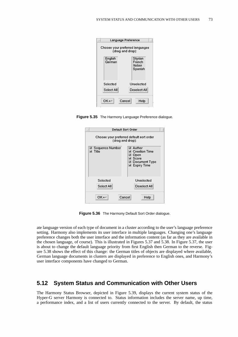
SYSTEM STATUS AND COMMUNICATION WITH OTHER USERS 73
Figure 5.35 The Harmony Language Preference dialogue.
Figure 5.36 The Harmony Default Sort Order dialogue.
ate language version of each type of document in a cluster according to the user’s language preferencesetting. Harmony also implements its user interface in multiple languages. Changing one’s languagepreference changes both the user interface and the information content (as far as they are available inthe chosen language, of course). This is illustrated in Figures 5.37 and 5.38. In Figure 5.37, the useris about to change the default language priority from first English then German to the reverse. Fig-ure 5.38 shows the effect of this change: the German titles of objects are displayed where available,German language documents in clusters are displayed in preference to English ones, and Harmony’suser interface components have changed to German.
5.12 System Status and Communication with Other Users
The Harmony Status Browser, depicted in Figure 5.39, displays the current system status of theHyper-G server Harmony is connected to. Status information includes the server name, up time,a performance index, and a list of users currently connected to the server. By default, the status
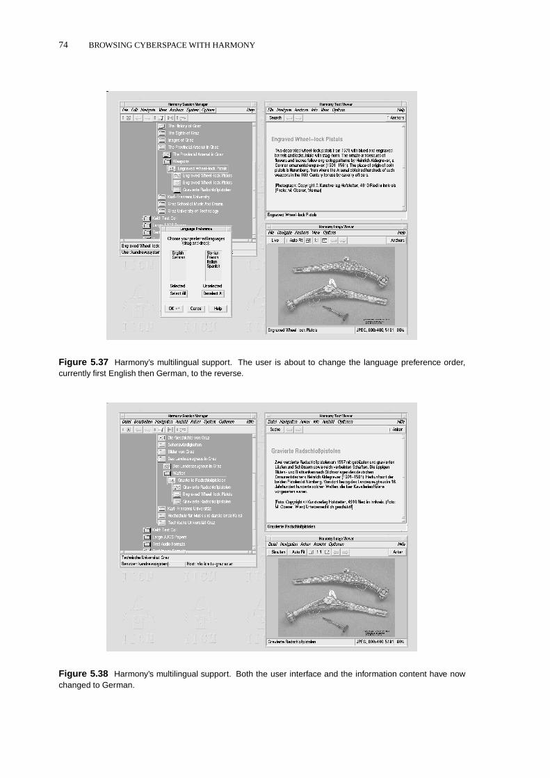
74 BROWSING CYBERSPACE WITH HARMONY
Figure 5.37 Harmony’s multilingual support. The user is about to change the language preference order,currently first English then German, to the reverse.
Figure 5.38 Harmony’s multilingual support. Both the user interface and the information content have nowchanged to German.

SYSTEM STATUS AND COMMUNICATION WITH OTHER USERS 75
Figure 5.39 The Harmony Status Browser.
Figure 5.40 Sending messages between users in Harmony.
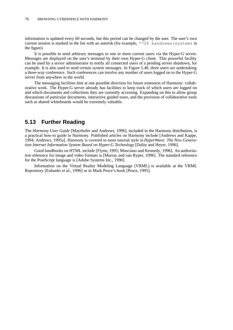
76 BROWSING CYBERSPACE WITH HARMONY
information is updated every 60 seconds, but this period can be changed by the user. The user’s owncurrent session is marked in the list with an asterisk (for example,*728 kandrews(system) inthe figure).
It is possible to send arbitrary messages to one or more current users via the Hyper-G server.Messages are displayed on the user’s terminal by their own Hyper-G client. This powerful facilitycan be used by a server administrator to notify all connected users of a pending server shutdown, forexample. It is also used to send certain system messages. In Figure 5.40, three users are undertakinga three-way conference. Such conferences can involve any number of users logged on to the Hyper-Gserver from anywhere in the world.
The messaging facilities hint at one possible direction for future extension of Harmony: collab-orative work. The Hyper-G server already has facilities to keep track of which users are logged onand which documents and collections they are currently accessing. Expanding on this to allow groupdiscussions of particular documents, interactive guided tours, and the provision of collaborative toolssuch as shared whiteboards would be extremely valuable.
5.13 Further ReadingTheHarmony User Guide[Mayrhofer and Andrews, 1996], included in the Harmony distribution, isa practical how-to guide to Harmony. Published articles on Harmony include [Andrews and Kappe,1994; Andrews, 1995a]. Harmony is covered in more tutorial style inHyperWave: The New Genera-tion Internet Information System Based on Hyper-G Technology[Dalitz and Heyer, 1996].
Good handbooks on HTML include [Flynn, 1995; Musciano and Kennedy, 1996]. An authorita-tive reference for image and video formats is [Murray and van Ryper, 1996]. The standard referencefor the PostScript language is [Adobe Systems Inc., 1990].
Information on the Virtual Reality Modeling Language (VRML) is available at the VRMLRepository [Eubankset al., 1996] or in Mark Pesce’s book [Pesce, 1995].

6 Building Cyberspace with Harmony
This chapter deals with Harmony’s extensive information management and authoring fa-cilities. It is a revised version of material first published in Chapter 23 of HyperWave: TheNext Generation Web Solution, Addison-Wesley, May 1996 [Andrews, 1996a].
6.1 Moving Beyond the Provider-Consumer ParadigmAlthough it was designed with collaboration and remote authoring in mind, the World Wide Webtoday is primarily an environment where providers provide information and users consume informa-tion1. Hyper-G goes a step beyond this paradigm, blurring the distinction between users and authors:depending on their access rights, every user with an account on the Hyper-G server is also an author.
In addition to browsing and navigating, my second major goal for the Harmony client was toprovide extensive in-built authoring facilities, which would be available to authors working on remotemachines via the Internet and thus open up all kinds of possibilities for collaborative authoring andvirtual communities. Given appropriate access permissions, for example, I can work on a documentcollection at the University of Auckland, or can grant you the reader write access to certain collectionsor documents on our Hyper-G server here in Graz.
The notable contribution of Harmony in this respect is its suite of (remote) authoring and man-agement facilities, including:
� Structure editing in collections and clusters.
� Document editing while preserving links.
� Interactive graphical link editing in all media.
� Attribute editing.
� Interactive uploading, insertion, and deletion.
� Making annotations to documents and collections.
Most of these facilities have been available in Harmony since 1993 and 1994 and are only nowbeginning to become available in commercial Web packages such as Netscape LiveWire [Netscape,1996], Microsoft FrontPage [Microsoft, 1996], and Adobe SiteMill [Adobe, 1996]. However, asInformationWeek reporter Jason Levitt says [Levitt, 1996]:
“Unfortunately, due to a lack of Web standards, none of these tools allows you to manageWeb servers from a variety of vendors. Specifically, there is no agreed-upon method forremote management of Web servers–that is, to retrieve Web pages over a network, editthem, and then write them back to the server using HTTP.”
Interactive link editing and document editing facilities similar to those in Harmony were demonstratedas early as 1986 in the Intermedia system [Haanet al., 1992], but Intermedia ran only on Apple A/UXand its clients did not communicate with the server via the Internet.
A second novel contribution of Harmony is the remote management of user accounts and usergroups using a graphical tool called HarAdmin, which is described in Section 6.9.
1Tim Berners-Lee’s original Web browser on the Next platform did, in fact, support editing, but issues of security andauthentication have prevented widespread adoption of editing functionality over HTTP.
77

78 BUILDING CYBERSPACE WITH HARMONY
Figure 6.1 Keith Andrews’ home collection, where objects will be inserted.
6.2 Object and Document Creation
For the purposes of the following explanation, let us assume that a hypermedia collection containinga short tour of the city of Graz is to be created. A Hyper-G userkandrews has been created and thisuser has a home collection and full access rights to it. It is common practice to work on draft versionsof hyperdocuments in one’s home collection, possibly protected from outside access, and later moveor plug them into an appropriate location in the collection structure and make them visible. Figure 6.1shows Keith Andrews’ home collection just prior to starting work on this task.
Creating Collections and Clusters
The Harmony Insert Dialogue is used both to create completely new Hyper-G objects and to uploadfiles accessible on the UNIX file system onto the server. Figure 6.2 shows the Insert Dialogue beingused to create a collection for the tour of Graz. The collection is calledA Short Tour of Grazin English andEine kurze Reise durch Graz in German. The author (or owner) of thecollection iskandrews , and the collection is protected so that only members of the groupiicmcan read it initially. A reasonably intuitive symbolic name,graztour , has been assigned to thecollection; this name will later appear in URLs referencing the collection.
By default, objects are inserted into the collection current at the time the dialogue was activated.A different collection can be specified by selecting the desired collection and pressing the Insert Di-alogue’sCurrent button. Keywords and a description could also be associated with the collection,but these have been left empty for the time being. When theInsert button is pressed, this newempty collection is inserted as a sub-collection ofKeith Andrews’ Home Collection :

OBJECT AND DOCUMENT CREATION 79
Figure 6.2 Inserting a collection with the Harmony Insert Dialogue.
Figure 6.3 Inserting a cluster.
Creating clusters is equally straightforward. In Figure 6.3 a cluster is being inserted into thepreviously created collection. The cluster has been given both English and German titles and hasinherited the same access rights as its parent collection (by default, the Insert Dialogue initialises theRights attribute to the same value as the new object’s parent collection). Titles in additional languagescould be assigned using theAdd button. The cluster is created and inserted into the collectionAShort Tour of Graz :

80 BUILDING CYBERSPACE WITH HARMONY
Figure 6.4 Uploading a text document.
Of course, at this point the newly created cluster is still empty — it is time to learn how toupload documents onto the server.
Inserting Documents
By choosingNew: Text in the Insert Dialogue’s selector, text documents can be inserted into theHyper-G server. The text can either be uploaded from an existing file or created from scratch inan editor. Figure 6.4 shows the text documentgraz-en.html being uploaded from the user’sUNIX home directory into the previously created cluster. Text documents are generally written inHTML, although Hyper-G’s original text format HTF is still supported. In the future, support willbe available for arbitrary SGML documents with appropriate DTDs and style sheets. Clicking on theEditor button rather than specifying a filename would cause Harmony to start an empty editor forthe new document, rather than uploading it from a file.
Since this particular text is written in English, only an English title has been assigned. Afterrepeating the same Insert procedure for the equivalent German textgraz-ge.html , the clusternow contains two member text documents:

OBJECT AND DOCUMENT CREATION 81
Figure 6.5 The newly uploaded text document.
These documents can be displayed in the Harmony Text Viewer like any other text documentsby simply double-clicking their icons. Figure 6.5 shows the first two paragraphs of the English text.
Let us continue the example collection about Graz. Three small JPEG images will now beuploaded into the previously created clusterIntroducing Graz to be used later as inline images.The Insert Dialogue for uploading an image looks like the one in Figure 6.6. Since these images areindependent of language, they are given titles in both English and German. The wordInline inthe titles is purely for the author’s information, it is not interpreted by the system in any special way.After uploading all three JPEG images, the cluster now has five member documents:
At this point, each image can be inspected in the Harmony Image Viewer, as illustrated inFigure 6.7 for the Clock Tower image. Note that the user has turned the AutoFit feature off, so as notto distort the small inline image by overly enlarging it.
The Insert Dialogue can, in fact, be used to insert any kind of document or collection. The newobject’s type is simply chosen from among the choices in theNewselector. The Harmony SessionManager performs a rudimentary magic number check on documents prior to uploading them, so asto detect when a document would be uploaded as the wrong type, for example an image declared as atext document. In such cases a warning dialogue appears.

82 BUILDING CYBERSPACE WITH HARMONY
Figure 6.6 Inserting an image document.
Figure 6.7 Inspecting the new image document.
PostScript documents and 3d models, which may be very large in uncompressed form but usu-ally respond well to compression, are generally compressed (GNU gzip or UNIX compress) exter-nally by the user before inserting them into the Hyper-G server. Transparently to the end user, clientsretrieve the compressed files across the Net, hence saving bandwidth, and decompress them locally.

DOCUMENT EDITING 83
Figure 6.8 Inserting a remote WWW document.
Creating Remote Objects
Remote objects include documents and directories on WWW, Gopher and ftp servers, and telnetsessions to remote sites. Access to such remote objects from within a Hyper-G context is achieved bycreating a Hyper-G remote object to represent the remote entity and specifying its attributes (such asHost and Port) accordingly.
To continue with our example, Bert Bos of the University of Groningen in Holland (and nowwith W3C) has, on his WWW server, a set of photographs of the Arsenal in Graz, which he tookduring his 1993 visit. Figure 6.8 shows the Insert dialogue being used to create a reference to theremote WWW page introducing this set of photographs. The object appears in the collection structureas a new text document:
The object can now be accessed with Harmony or any other Web browser, as shown in Figure 6.9using Netscape.
6.3 Document Editing
As well as facilities for uploading documents, Harmony provides facilities for interactively editingdocuments already on a Hyper-G server. There are two mechanisms in Harmony for document edit-ing. First, the Text and Image viewers are equipped with an Edit function. When theEdit function isactivated, the document viewer writes a temporary copy of the document it is displaying to a file andstarts an external editor to edit the temporary file. Modifications to the temporary file (after savingto disk) can be optionally previewed in the document viewer. When the external editor is exited, thedocument viewer presents a dialogue box asking the user whether or not the modified version of thedocument should be uploaded back to the Hyper-G server, replacing the original.
As an alternative, anEdit API is available, which can be called through Harmony’s Tools menuto edit any type of document. The Edit process runs alongside Harmony and its small Edit window isalways available to edit the currently selected document.

84 BUILDING CYBERSPACE WITH HARMONY
Figure 6.9 Viewing the remote WWW object just inserted.
Editing Text Documents
The Harmony Text Viewer’s Edit function starts the Emacs editor by default. Figure 6.10 showsEmacs being used to edit the English text about Graz. Having corrected a spelling mistake andemphasised the wordssecond largest, the user has saved the file to disk (without exiting Emacs) andin is previewing the modified document in the Text Viewer.
Harmony can, of course, be configured to use any editor for text documents, for example adedicated HTML authoring tool such as AsWedit (as shown in Figure 6.11) or Symposia. To specifythe desired editing tool, use the Text Viewer’seditcommand X resource:
Harmony.Text.editcommand: asWedit
The name of the temporary file is appended to the command automatically. When editing is finishedand the external editor has been exited, the Harmony Text Viewer presents a dialogue box asking theuser whether or not to insert the modified version of the text document.
Hyperlinks in Hyper-G are not stored embedded in documents but externally in a separate linkdatabase. Anchor regions in a text document are defined by character offsets. To ensure that linkanchors in a text remain associated with the same text region (word, phrase and so on) when a file isedited, they are merged into the temporary text file prior to editing. Hence, link anchors slide aroundwith their associated regions as the text is edited. When editing is finished, the links are extracted andre-inserted into the Hyper-G link database, and the document per se is inserted back into the Hyper-Gdocument server.
Editing Image Documents
Interactive editing of images is analogous to text editing. The image is written to a temporary file bythe Harmony Image Viewer and an external editor is started. Figure 6.12 shows an image used as a

DOCUMENT EDITING 85
Figure 6.10 Editing a text with Emacs from the Harmony Text Viewer.
Figure 6.11 Editing a HTML text with AsWedit from the Harmony Text Viewer.

86 BUILDING CYBERSPACE WITH HARMONY
Figure 6.12 Editing an image with XV.
texture in a 3d cityscape of Graz being edited with XV. When the editor is exited, the Image Viewerasks whether or not to upload the new image in place of the original version.
Hyperlinks in image documents are defined in terms of a virtual coordinate space, where (0,0)is the lower left corner of the image and (1,1) the upper right. Operations which do not change theaspect ratio of the image, such as making it brighter or saving in a different format, are perfectly safe.However, cropping or otherwise changing the aspect ratio of the image will cause link anchors in theimage to slide, since the Image Viewer does not attempt to remap the positions of link anchors. Insuch cases, it is necessary to manually check and, if necessary, reposition any anchors in the image.
6.4 Modifying Attributes
The attributes of a collection, cluster, or document can be displayed in Harmony’s Attribute win-dow by right-clicking the corresponding object in the collection browser or alternatively via SessionManager or document viewer menus. Staying with our Graz example, the attributes for the clusterIntroducing Graz are shown in Figure 6.13. This is the cluster we created previously as anintroduction to our collectionA Short Tour of Graz :

MODIFYING ATTRIBUTES 87
Figure 6.13 The Harmony Attribute Window.
Figure 6.14 Editing attributes in the Attribute Window.
Clicking the Edit button puts the Attribute window into edit mode, as can be seen in Fig-ure 6.14. The attributes are rearranged automatically, so that those which may be modified are at thebottom of the list. In the figure, the cluster is being specified as the collection head for the collection to
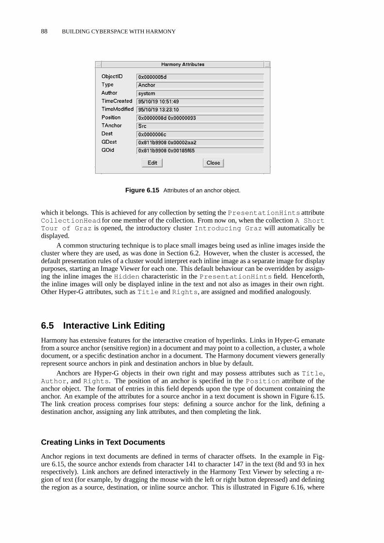
88 BUILDING CYBERSPACE WITH HARMONY
Figure 6.15 Attributes of an anchor object.
which it belongs. This is achieved for any collection by setting thePresentationHints attributeCollectionHead for one member of the collection. From now on, when the collectionA ShortTour of Graz is opened, the introductory clusterIntroducing Graz will automatically bedisplayed.
A common structuring technique is to place small images being used as inline images inside thecluster where they are used, as was done in Section 6.2. However, when the cluster is accessed, thedefault presentation rules of a cluster would interpret each inline image as a separate image for displaypurposes, starting an Image Viewer for each one. This default behaviour can be overridden by assign-ing the inline images theHidden characteristic in thePresentationHints field. Henceforth,the inline images will only be displayed inline in the text and not also as images in their own right.Other Hyper-G attributes, such asTitle andRights , are assigned and modified analogously.
6.5 Interactive Link Editing
Harmony has extensive features for the interactive creation of hyperlinks. Links in Hyper-G emanatefrom a source anchor (sensitive region) in a document and may point to a collection, a cluster, a wholedocument, or a specific destination anchor in a document. The Harmony document viewers generallyrepresent source anchors in pink and destination anchors in blue by default.
Anchors are Hyper-G objects in their own right and may possess attributes such asTitle ,Author , andRights . The position of an anchor is specified in thePosition attribute of theanchor object. The format of entries in this field depends upon the type of document containing theanchor. An example of the attributes for a source anchor in a text document is shown in Figure 6.15.The link creation process comprises four steps: defining a source anchor for the link, defining adestination anchor, assigning any link attributes, and then completing the link.
Creating Links in Text Documents
Anchor regions in text documents are defined in terms of character offsets. In the example in Fig-ure 6.15, the source anchor extends from character 141 to character 147 in the text (8d and 93 in hexrespectively). Link anchors are defined interactively in the Harmony Text Viewer by selecting a re-gion of text (for example, by dragging the mouse with the left or right button depressed) and definingthe region as a source, destination, or inline source anchor. This is illustrated in Figure 6.16, where

INTERACTIVE LINK EDITING 89
Figure 6.16 Interactive definition of a source anchor in a text document.
Figure 6.17 The Harmony Link Creator.
a source anchor is being specified from the word “Schloßberg” in the text. Activating the functionDefine as Source brings up Harmony’s Link Creator, depicted in Figure 6.17. The source of the linkhas been entered in the corresponding Source Anchor box. The user has also defined the destinationof the link to be a cluster called “The Castle Hill.” Clicking the buttonCreate Link completes thelink and it can be followed immediately thereafter.
An appropriate destination was found in this case by searching the Hyper-G server, as can beseen in Figure 6.18 which illustrates the entire course of this sample link creation process. The actualdefinition of a destination anchor proceeds in a manner similar to defining a source anchor, with thespecial case that, by default, a destination anchor in a text document covers the whole document.

90 BUILDING CYBERSPACE WITH HARMONY
Figure 6.18 The entire link creation procedure in Harmony.
Placing Inline Images in Text Documents
Hyper-G implements inline images in text documents simply as a special link of typeinline . Theprocedure for placing inline images is identical to that for creating links. A region of the text ismarked, immediately preceding which the image will be placed. In Figure 6.19, the wordGraz hasbeen selected and the image will be inserted directly before it. From the Text Viewer menu, thisselection is then defined to be an inline source anchor, bringing up the Harmony Link Creator shownin Figure 6.20.
The destination of the inline link (that is, the image to be inlined) is now specified, and theinline link is created. The resulting text with inlined image is shown in Figure 6.21. The inline imagecan be centered by editing the text document and adding the appropriate tag. Assuming that the usercreates inline links to all three small images previously uploaded, the finished introductory documentlooks something like that shown in Figure 6.22 when accessed with a standard Web browser such asNetscape.
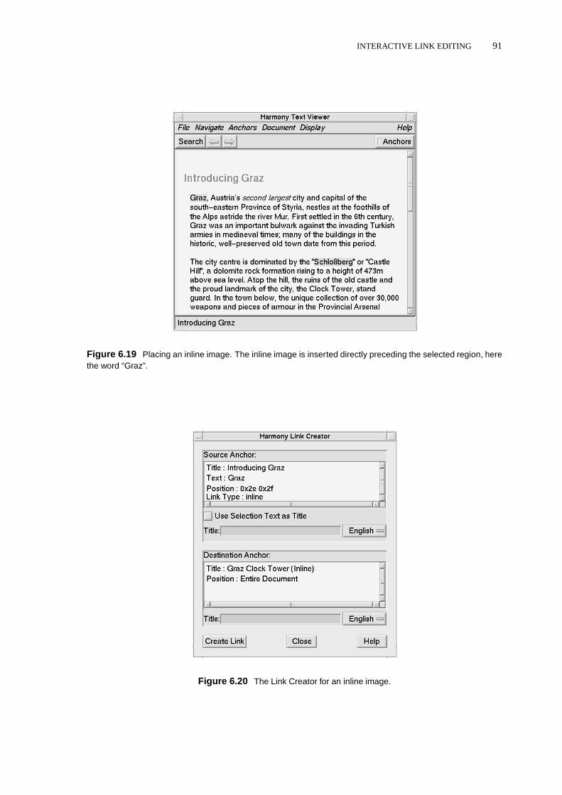
INTERACTIVE LINK EDITING 91
Figure 6.19 Placing an inline image. The inline image is inserted directly preceding the selected region, herethe word “Graz”.
Figure 6.20 The Link Creator for an inline image.
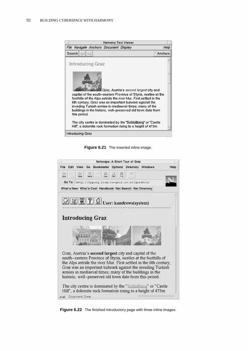
92 BUILDING CYBERSPACE WITH HARMONY
Figure 6.21 The inserted inline image.
Figure 6.22 The finished introductory page with three inline images.

INTERACTIVE LINK EDITING 93
Figure 6.23 Source anchors in an image document.
Creating Links in Image Documents
Anchor regions in image documents are defined in terms of a virtual coordinate space, where (0,0) isthe lower left corner of the image and (1,1) the upper right. The image shown in Figure 6.23 has twosource anchors (links) defined, a circle and a polygon, whose positions are defined in thePositionattribute as follows:
Circle 0.921321 0.283395 0.177331Polygon 0.0734733 0.642748, 0.0734733 0.642748, ...
Link anchors are defined interactively by selecting an anchor shape (in the Anchors menu) andusing the right mouse button to define the region. For rectangular, circular and elliptical anchorshapes, it is sufficient to drag and release the right mouse button to define the anchor region. Forpolygonal regions, each right mouse click defines a vertex of the polygon and a middle-click com-pletes the polygon. Any freshly marked anchor region can be repositioned by Control-right-draggingthe shape. Once the anchor region is satisfactory, the region is defined as a source or destinationanchor, and the Link Creator dialogue appears. The procedure now continues in the same way asexplained for text anchors.
A destination anchor in an image will cause the image to be panned so that the region of theimage containing the anchor is in view. This is illustrated in Figure 6.24, where a link has beenfollowed to a particular region of a large map of Graz.
Creating Links in Film Documents
Anchors in film clips are created by specifying the position and size of an anchor region for a set ofkey frames. Linear or spline interpolation is used to determine the position of an anchor in betweenkey frames. Anchors may be rectangular, circular, or elliptical in shape. The sequence of screen shotsin Figure 6.25 shows a circular link anchor being created to track the helmet of a piece of cavalryarmour. The anchor’s size and position are first specified for frame 1 of the film, then for frames 15,30, and 45. The marked anchor region can be played back to check its effect and how it is interpolatedbetween key frames. When a satisfactory result has been achieved, the marked region is defined aseither a source or destination anchor using the Anchor menu. In this particular example, an anchor

94 BUILDING CYBERSPACE WITH HARMONY
Figure 6.24 Elliptical destination anchor in an image document.
Figure 6.25 Creating an anchor in a film clip.

INTERACTIVE LINK EDITING 95
Figure 6.26 Frame range as a destination anchor.
Figure 6.27 Destination anchor in an audio document.
was created with the followingPosition attribute:
Circle Linear 4: 1 0.45 0.675781 0.204084 ,
15 0.60625 0.667969 0.201556 ,
30 0.7875 0.695312 0.208885 ,
45 0.99375 0.703125 0.234791
A simplified form of anchor, namely a range of frames, can be specified for a destination anchor.Figure 6.26 shows frames 196 to 370 of the Arsenal film clip being defined as the destination of alink. The frame range can be marked approximately by right-dragging across the play bar, or exactlyby entering the precise frames in the Settings panel.
Creating Links in Audio Documents
An anchor region in an audio document is defined by a starting and ending position (time) in the audiostream. Currently, only destination anchors are supported, that is, links can be made to particular

96 BUILDING CYBERSPACE WITH HARMONY
Figure 6.28 Creating a destination anchor in a PostScript document.
regions of an audio document. Figure 6.27 shows the Harmony Audio Player after a link has beenfollowed to the latter part of the document.
The Audio Player must be set up to use NAS (the Network Audio System) [Fulton and Renda,1994] in order to be able to process link anchors. When the Audio Player is configured to use a nativeaudio play command (which is currently the default due to the lack of a widely installed audio serversuch as NAS), the audio stream is simply passed on to this external program and not examined further.
Creating Links in PostScript Documents
An anchor region in a PostScript document is a rectangular region defined in terms of PostScript pagenumber and coordinates. A new region is marked by right-dragging the mouse. Figure 6.28 shows adestination anchor being defined in the Harmony PostScript Viewer to cover Figure 1.c of the article.Source anchors are typically highlighted by coloured frames, destination anchors by “lowlighting”the rest of the current page. Anchors in a PostScript document may be repositioned and resized byControl-right-dragging the mouse. Dragging a corner or an edge of an anchor resizes it, dragging theinterior repositions it. The repositioned link anchors can then be saved back into the server throughthe Anchors menu.

INTERACTIVE LINK EDITING 97
Figure 6.29 Creating a source anchor in a 3d model.
Creating Links in 3D Documents
In a 3d model, source and destination anchors are conceptually distinct. A source anchor can beattached to an arbitrary part of a 3d model. In the Graz model shown in Figure 6.29, a source anchoris being created from the Clock Tower object in the model to more detailed information about thetower. The currently marked object is highlighted by drawing its bounding box.
A destination anchor, on the other hand, is not attached to part of a model, but instead indicatesa specific camera position and orientation, that is, a specific view of the model. Destination anchorsare defined by navigating to the desired viewing position and then defining the current position as adestination anchor.
Link Attribute Modification
Since link anchors in Hyper-G are objects in their own right, they may possess attributes such asTitle , Author , and Rights . Selecting an anchor in a Harmony document viewer (by left-clicking) and choosing to display its attributes via the Anchors menu brings up Harmony’s standardAttributes window (see Section 6.4). The attributes shown in Figure 6.30 are those of the sourceanchor from the wordSchloßberg which was created in Section 6.5. The default access rightsallow the author of an anchor write access, and all other users read access. In our example, the authorof the anchor iskandrews , and hence the anchor object’s attributes may be edited, as shown inFigure 6.31, where a title has been added to the anchor.

98 BUILDING CYBERSPACE WITH HARMONY
Figure 6.30 Attributes of the Schloßberg anchor object.
Figure 6.31 Editing the anchor’s attributes.
Link Deletion
A link is deleted interactively by selecting its source anchor in the appropriate document viewer (left-clicking) and choosing theDelete item from the Anchors menu. In the Harmony Text Viewer,multiple anchors can be selected and then deleted in one operation by shift-left-clicking the anchors.Before actually performing the deletion, Harmony presents a confirmation dialogue box.
6.6 Structure Editing
A prime characteristic of Hyper-G is its ability to structure information into collections and sub-collections in a manner orthogonal to referential hyperlinks. This helps alleviate disorientation bypresenting a firm, perceivable structure to users. Harmony’s facilities for creating new collectionswere described in Section 6.2. Naturally, Harmony also has facilities for moving existing documentsand collections between collections and for making documents and collections members of multipleparent collections. These functions are currently provided via dialogues, but will soon be available

STRUCTURE EDITING 99
Figure 6.32 Moving a document or collection.
through a drag-and-drop operation directly in the collection browser.
Moving Objects
Assuming that theA Short Tour of Graz collection has been completed and is now in a pre-sentable form, the author may want to move it from his home collection into a publicly accessiblecollection. This is achieved with theMove command from the Edit menu, as shown in Figure 6.32.After the move operation, the collection has been removed from the home collection and made amember the collection namedgraz . This would also be the right time to adjust any access rights onthe collection and its members so that anonymous users can read its contents.
Copying Objects
The alternative to moving an object is to “copy” it into an additional collection. The object then be-longs both to the original collection and to the additional collection, and appears in both locations inthe collection hierarchy. The term “copy” is somewhat misleading, because the object is not physi-cally copied, it simply becomes a member of both collections (the same operation in HGTV is called“link”). Perhaps “join” or “insert” would be better names. The dialogue box for theCopy operationis shown in Figure 6.33.

100 BUILDING CYBERSPACE WITH HARMONY
Figure 6.33 “Copying” a document or collection.
Figure 6.34 Deleting a document or collection.
6.7 Deleting Objects
An object can be deleted interactively by selecting it and then activating theDelete function fromthe Edit menu. The Harmony Delete window shown in Figure 6.34 is presented. If the object belongsonly to one collection, then it is physically deleted, and by default so are any incoming and outgoinglinks associated with it. If the object is a member of multiple parent collections, then deleting itsimply removes it from the specified collection and has no further consequences. Specifying deletionof all occurrences forces the object’s removal from all parent collections and its physical deletion.Currently, collections can be physically deleted only if they are empty, that is, their members must bedeleted first.
6.8 Annotations
Conceptually, an annotation in Hyper-G is really just a special kind of link. Annotations are notrestricted to being pieces of text, but can be documents of any type. They are associated with thecollection, cluster, or document upon which they comment by a link of typeAnnotation .
Annotations are created using a variant of the Harmony Insert dialogue which was discussed inSection 6.2. To annotate an object, the object is selected and theAnnotate function in the HarmonySession Manager’s Edit menu is activated. Harmony presents the user with an Insert dialogue pre-configured for inserting an annotation. The annotation may either be uploaded from disk or createdafresh with an editor. In the example shown in Figure 6.35, a colleague (Vanessa Mayrhofer,vmayr )is editing a new annotation about the introductory clusterIntroducing Graz .
In the case of a textual annotation, a link back to the document being annotated is pre-insertedinto the template text document, as can be seen in Figure 6.36. When the comment or remark isfinished, the editor is exited, and a dialogue box asks for confirmation that the annotation should be

ANNOTATIONS 101
Figure 6.35 Creating an annotation to the Introducing Graz cluster.
Figure 6.36 The finished annotation.

102 BUILDING CYBERSPACE WITH HARMONY
Figure 6.37 The annotation relationship in the Local Map.
inserted into the server. By default, annotations are inserted into the collection to which the annotatedobject itself belongs, but this can be changed in the Insert dialogue. In the example, a new text docu-mentMention of Napoleon? (the annotation) has been inserted into the collectionA ShortTour of Graz to which the clusterIntroducing Graz belongs:
Since annotations are a kind of link type, annotation relationships can be comfortably viewedin Harmony’s Local Map. Figure 6.37 shows the Local Map for the annotation in our example.By annotating annotations, a structured discussion can evolve. A good example of this is HermannMaurer’s “Social Aspects of Telematics” course at Graz University of Technology, in which studentsand professors discuss a series of short essays online using pseudonyms. Figure 6.38 shows two levelsof the discussion about an essay concerning the dynamics of information.
6.9 Managing Users and User GroupsHarAdmin, shown in Figure 6.39 is a graphical administration tool for the interactive creation andmanagement of user accounts and user groups2 [Windisch, 1995]. Hyper-G users and groups are
2HarAdmin was designed by myself and Claudia Windisch and implemented by Claudia under my supervision for herMaster’s Thesis.

MANAGING USERS AND USER GROUPS 103
Figure 6.38 Structured discussion using annotations.
Figure 6.39 HarAdmin, the graphical administration tool for user accounts and user groups.
104 BUILDING CYBERSPACE WITH HARMONY
completely separate from UNIX users and groups. The attributes of a User object include a descrip-tion, (optional) home collection, various passwords, and so forth. The Account attribute embodies avirtual wallet from which amounts can be deducted.
A hierarchical scheme of groups and subgroups can be defined, with groups potentially belong-ing to multiple parent groups. Hyper-G access rights can be assigned per document or collection on auser or group basis, for example using Harmony’s attribute editor.
6.10 Further ReadingNumerous HTML authoring tools are now available for all major platforms, including asWedit[Stochniol, 1996] and Symposia [INRIA/GRIF, 1996] for UNIX. The most popular image manipula-tion tools for UNIX are XV [Bradley, 1996] and the PBMPLUS utility suite [Poskanzer, 1996]. Thebest resource for MPEG is Luigi Filippini’s online Web site [Filippini, 1996]. The mpegUtil utility[Lougher, 1996] allows MPEG clips to be extracted and concatenated. A good printed source of infor-mation on image and video formats isGraphics File Formatsby Murray and van Ryper [1996]. TheNetwork Audio System is described in [Fulton and Renda, 1994]. The Audio page of the WWW Vir-tual Library (available athttp://cnidr.org/talks/whyzdist.html ) has numerous linksto audio software and samples. The VRML Repository [Eubankset al., 1996] maintains a list ofmodeling tools and conversion utilities for VRML.

7 Beholding Cyberspace with VRweb
In this chapter, I present the Harmony 3d Scene Viewer and its successor VRweb. Parts ofthis chapter were published in VRweb: A Multi-System VRML Viewer, Proceedings of theFirst Annual Symposium on the Virtual Reality Modeling Language (VRML 95), San Diego,California, Dec. 1995 [Pichler et al., 1995] and Hooking Up 3-Space: Three-DimensionalModels as Fully-Fledged Hypermedia Documents, in Multimedia, Hypermedia, and VirtualReality, Springer LNCS 1077, 1996 [Andrews and Pichler, 1996]. The Harmony 3D SceneViewer was first presented in December 1992 at the European Conference on Hypertextin Milan [Andrews, 1992].
7.1 3D Hypermedia and the Internet
From the start of my work with Hyper-G and Harmony in 1991, and drawing on the work done inIntermedia [Haanet al., 1992], it was clear to me that the storage of hyperlinks in a separate linkdatabase would enablereal hypermedia, i.e. linking from and to all kinds of media. My previousbackground in computer graphics also made it natural to support 3d models as one of the standardhypermedia document types in Hyper-G and in the Harmony client.
To my knowledge, my work on 3d hypermedia in Hyper-G combining 3d models and hyperlink-ing across the Internet, was the first such work world-wide. I presented our initial work in this area,the Harmony 3d Scene Viewer1, as a poster at the European Conference on Hypertext in Milan inDecember 1992 [Andrews, 1992] (see Figure 7.1); the poster was subsequently also put on display atXerox PARC. The Harmony 3d Scene Viewer would later become the VRweb browser for the VirtualReality Modeling Language (VRML) [Pesce, 1995].
The scientific contribution of the Harmony 3d Scene Viewer and later of VRweb is manifold. Wedemonstrated that 3d models can be integrated into a real hypermedia system as a standard documenttype, with full hyperlinking capability. The Harmony 3d Scene Viewer embodied in 1993 (!) much ofthe functionality found in today’s VRML browsers: browsing 3d models across the Internet, followinghyperlinks to models and other documents, as well as interactive link editing facilities still not widelyavailable in today’s VRML browsers.
Today, VRweb is available from some 20 ftp mirror sites world-wide. It has been distributed onCD-ROM in 10 books and magazines, and was demonstrated by Sun Microsystems in the context of a3d decision support system at their SIGGRAPH’96 booth. The VRweb home page:http://www.iicm.edu/vrweb is one of the most requested pages on the IICM server and is accessed around5000 times a month. Jim Collins said of VRweb in PC Magazine in October 1995:
“We found that scenes created with VRweb were a lot less jaggy and appeared more real-istic than those created in WebSpace. . . ”
and Howard Wen said in Wired magazine in February 1996:
“VRweb is just such a facilitating program. It’s a no-fuss VRML viewer that’s user-friendlyand simple to use. Additionally, because its programming is relatively stable, VRwebserves as a good introduction to VRML browsing.”
1The Harmony 3d Scene Viewer was designed by myself and Michael Pichler and implemented by Michael for hisMaster’s Thesis, under my supervision.
105
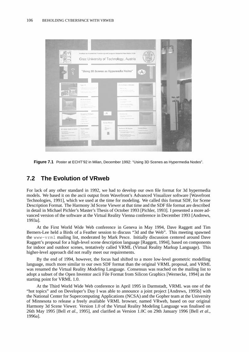
106 BEHOLDING CYBERSPACE WITH VRWEB
Figure 7.1 Poster at ECHT’92 in Milan, December 1992: “Using 3D Scenes as Hypermedia Nodes”.
7.2 The Evolution of VRweb
For lack of any other standard in 1992, we had to develop our own file format for 3d hypermediamodels. We based it on the ascii output from Wavefront’s Advanced Visualizer software [WavefrontTechnologies, 1991], which we used at the time for modeling. We called this format SDF, for SceneDescription Format. The Harmony 3d Scene Viewer at that time and the SDF file format are describedin detail in Michael Pichler’s Master’s Thesis of October 1993 [Pichler, 1993]. I presented a more ad-vanced version of the software at the Virtual Reality Vienna conference in December 1993 [Andrews,1993a].
At the First World Wide Web conference in Geneva in May 1994, Dave Raggett and TimBerners-Lee held a Birds of a Feather session to discuss “3d and the Web”. This meeting spawnedthe www-vrml mailing list, moderated by Mark Pesce. Initially discussion centered around DaveRaggett’s proposal for a high-level scene description language [Raggett, 1994], based on componentsfor indoor and outdoor scenes, tentatively called VRML (Virtual Reality Markup Language). Thishigher-level approach did not really meet our requirements.
By the end of 1994, however, the focus had shifted to a more low-level geometric modellinglanguage, much more similar to our own SDF format than the original VRML proposal, and VRMLwas renamed the Virtual RealityModelingLanguage. Consensus was reached on the mailing list toadopt a subset of the Open Inventor ascii File Format from Silicon Graphics [Wernecke, 1994] as thestarting point for VRML 1.0.
At the Third World Wide Web conference in April 1995 in Darmstadt, VRML was one of the“hot topics” and on Developer’s Day I was able to announce a joint project [Andrews, 1995b] withthe National Center for Supercomputing Applications (NCSA) and the Gopher team at the Universityof Minnesota to release a freely available VRML browser, named VRweb, based on our originalHarmony 3d Scene Viewer. Version 1.0 of the Virtual Reality Modeling Language was finalised on26th May 1995 [Bellet al., 1995], and clarified as Version 1.0C on 29th January 1996 [Bellet al.,1996a].

THE VIRTUAL REALITY MODELING LANGUAGE (VRML) 107
#VRML V1.0 ascii
Separator {
ShapeHints { vertexOrdering COUNTERCLOCKWISE shapeType SOLID faceType CONVEX }
DEF Mat_pinebrown Material { diffuseColor 0.2576 0.1225 0.0007 }DEF Mat_bluetest Material { diffuseColor 0.7692 0.6967 0.5908 }:DEF Mat_rust Material { diffuseColor 0.1996 0.0567 0.0274 }DEF Mat_sand Material { diffuseColor 0.2863 0.2367 0.1696 }
PointLight {color 0.7633 0.7633 0.7633location -5 2 5}
TransformSeparator {DEF Obj_3 Group {Coordinate3 { point [-1.13195 1.87823 1.13195,-1.13195 -1.87823 1.13195,
:1.13186 -1.87823 1.13204,1.13186 1.87823 1.13204]} # Obj_3 199 vertices
USE Mat_pinebrownIndexedFaceSet { coordIndex [9,13,12,8,-1,
:25,29,30,26,-1]}
USE Mat_rustIndexedFaceSet { coordIndex [34,33,32,-1,
:37,40,38,35,-1]}..
USE Mat_towerIndexedFaceSet { coordIndex [187,188,189,190,-1,191,192,193,194,-1,195,196,197,198,-1]}} # Obj_3: 141 elements}
} # end of file
Figure 7.2 An example of a typical VRML 1.0 geometry file (shortened for brevity).
7.3 The Virtual Reality Modeling Language (VRML)
The Virtual Reality Modeling Language [Pesce, 1995; Eubankset al., 1996], or VRML for short, hasbecomethestandard format for the storage and interchange of 3d models on the Net. VRML is basedon the ascii form of Silicon Graphics’ Inventor [Wernecke, 1994] file format, an extensive, proven3d graphics file format which includes a variety of special-purpose nodes. VRML adopted Inventor’snode-based hierarchical structure, field syntax, and instancing mechanism, but left out a number ofits special-purpose and more esoteric features. VRML defines nodes for geometry (both polygon-

108 BEHOLDING CYBERSPACE WITH VRWEB
based and primitive shapes), text, grouping, multiple levels of detail, transformations (elementaryand arbitrary matrices), coordinates, normal data, properties (materials, textures), rendering attributes(bindings and shape hints), light sources (positional, directional, spot lights), and camera definitions(perspective and orthographic).
The example in Figure 7.2 gives an idea of the structure of a typical VRML 1.0 file. The filebegins with a standard header line to identify it as a VRML 1.0 ascii file. Then a set of materials aredefined using the DEF construct. Light sources are defined (here point sources). Then follows theactual geometry of the model: first a set of 199 vertices is defined, then polygons (IndexedFaceSet)using these vertices. Each polygon is assigned a material with the USE construct.
Other VRML 1.0 constructs include LOD (level of detail), a grouping node allowing finer orcourser models to be loaded depending upon the distance from the viewer. WWWInline is a nodeto include an arbitrary (sub)model given its URL. WWWInline nodes allow a scene to be split intoparts which may be fetched on demand. For example, when navigating a large, complex model,components of the model might be fetched only as one approaches them (important on a slow networkconnection). The WWWAnchor node supports a link anchor attached to an arbitrary component ofa model; anchors can be clicked to load a related VRML model or indeed any other type of file.Important for the backward-compatibility of extensions to VRML is the possibility for a node toprovide a description of its fields and (optionally) the name of a base node that can be used as itssubstitute.
VRML 1.0 supports onlystaticscene descriptions, only the viewer moves within the model andobjects do not have any associated behaviour. Such scripting functionality is the declared goal ofVRML 2.0, the specification for which was released on 4th August 1996 [Bellet al., 1996b]. TheVRML Architecture Group (VAG) [VAG, 1996], a group of eight technical experts, now coordinatesdevelopment of the VRML specifications.
7.4 The VRweb VRML Browser
VRweb began as a joint project between IICM (home of Hyper-G), NCSA (home of Mosaic), and theUniversity of Minnesota (home of Gopher), drawing on several years of experience at the IICM withthe Harmony 3D Scene Viewer [Andrews, 1992; Andrews and Pichler, 1996] for Hyper-G, whichbecame the base of VRweb. VRweb is designed to work with both WWW and Hyper-G clients ona variety of platforms. It is currently available for most common UNIX platforms (SGI IRIX, SunSolaris, Sun OS, DEC Alpha, DEC ULTRIX, HP-UX, IBM AIX, and LINUX) as well as WindowsNT, 3.1, and 95. VRweb source code is available free of charge for non-commercial use under theGNU General Public Licence, providing a platform for research and experiment. Unlike other VRMLviewers available in source code, VRweb doesnot require additional commercial libraries like Open-Inventor or Motif, it is based entirely on freely available software components (see Section 7.7 formore detail about VRweb’s software architecture). Figure 7.3 shows VRweb displaying Lightscape’s[Lightscape, 1996] VRML model of the chamber of Jerusalem City Hall. Currently, VRweb supportsVRML 1.0, but moves are underway to re-write most of VRweb in Java and add support for VRML2.0.
7.5 The VRweb User Interface
The VRweb window is divided vertically into four areas: menu bar, tool bar, display area, and statusbar. The menu bar provides access to the full functionality of VRweb, the tool bar and additionalaccelerator keys provide quick access to commonly used functions.
VRweb supports five rendering modes: wire frame, hidden line, flat shading, smooth shading,and texturing; the rendering mode specified in the VRML file can be overridden. A separate renderingmode may be specified for use during interactive navigation. For example, on a display without

THE VRWEB USER INTERFACE 109
Figure 7.3 The VRweb VRML viewer displaying Lightscape’s model of Jerusalem City Hall.
Figure 7.4 VRweb for Windows in Heads-Up navigation mode. Icons are overlaid atop the viewing area forlooking, walking, vertical/sideways motion, and point-of-interest navigation. The rendering mode may be setseparately for faster interactive navigation.
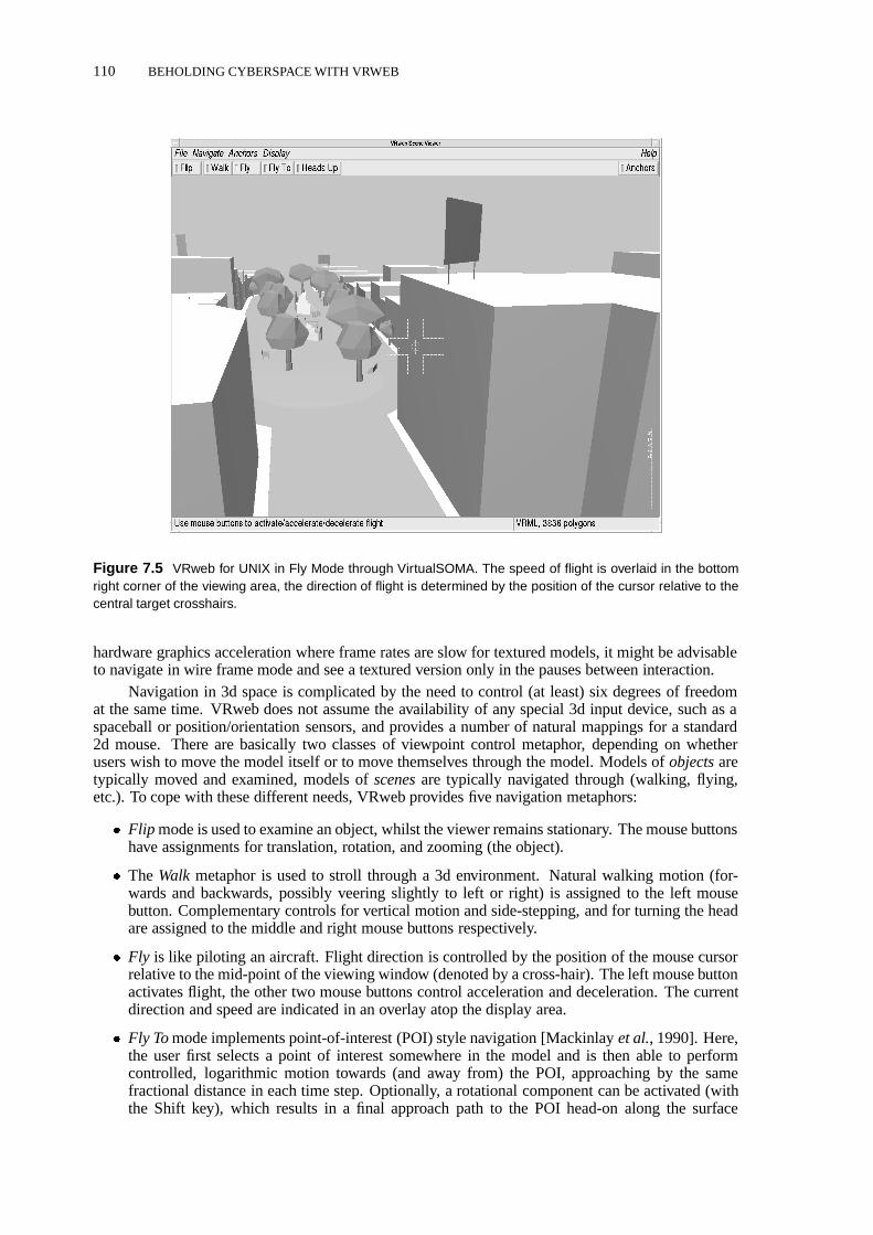
110 BEHOLDING CYBERSPACE WITH VRWEB
Figure 7.5 VRweb for UNIX in Fly Mode through VirtualSOMA. The speed of flight is overlaid in the bottomright corner of the viewing area, the direction of flight is determined by the position of the cursor relative to thecentral target crosshairs.
hardware graphics acceleration where frame rates are slow for textured models, it might be advisableto navigate in wire frame mode and see a textured version only in the pauses between interaction.
Navigation in 3d space is complicated by the need to control (at least) six degrees of freedomat the same time. VRweb does not assume the availability of any special 3d input device, such as aspaceball or position/orientation sensors, and provides a number of natural mappings for a standard2d mouse. There are basically two classes of viewpoint control metaphor, depending on whetherusers wish to move the model itself or to move themselves through the model. Models ofobjectsaretypically moved and examined, models ofscenesare typically navigated through (walking, flying,etc.). To cope with these different needs, VRweb provides five navigation metaphors:
� Flip mode is used to examine an object, whilst the viewer remains stationary. The mouse buttonshave assignments for translation, rotation, and zooming (the object).
� The Walk metaphor is used to stroll through a 3d environment. Natural walking motion (for-wards and backwards, possibly veering slightly to left or right) is assigned to the left mousebutton. Complementary controls for vertical motion and side-stepping, and for turning the headare assigned to the middle and right mouse buttons respectively.
� Fly is like piloting an aircraft. Flight direction is controlled by the position of the mouse cursorrelative to the mid-point of the viewing window (denoted by a cross-hair). The left mouse buttonactivates flight, the other two mouse buttons control acceleration and deceleration. The currentdirection and speed are indicated in an overlay atop the display area.
� Fly Tomode implements point-of-interest (POI) style navigation [Mackinlayet al., 1990]. Here,the user first selects a point of interest somewhere in the model and is then able to performcontrolled, logarithmic motion towards (and away from) the POI, approaching by the samefractional distance in each time step. Optionally, a rotational component can be activated (withthe Shift key), which results in a final approach path to the POI head-on along the surface
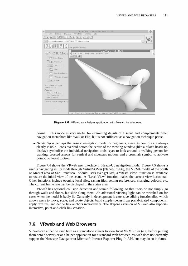
VRWEB AND WEB BROWSERS 111
Figure 7.6 VRweb as a helper application with Mosaic for Windows.
normal. This mode is very useful for examining details of a scene and complements othernavigation metaphors like Walk or Flip, but is not sufficient as a navigation technique per se.
� Heads Upis perhaps the easiest navigation mode for beginners, since its controls are alwaysclearly visible. Icons overlaid across the centre of the viewing window (like a pilot’s heads-updisplay) symbolise the individual navigation tools: eyes to look around, a walking person forwalking, crossed arrows for vertical and sideways motion, and a crosshair symbol to activatepoint-of-interest motion.
Figure 7.4 shows the VRweb user interface in Heads-Up navigation mode. Figure 7.5 shows auser is navigating in Fly mode through VirtualSOMA [Planet9, 1996], the VRML model of the Southof Market area of San Francisco. Should users ever get lost, a “Reset View” function is availableto restore the initial view of the scene. A “Level View” function makes the current view horizontal.Other functions include opening local files, saving files, setting preferences, changing colours, etc.The current frame rate can be displayed in the status area.
VRweb has optional collision detection and terrain following, so that users do not simply gothrough walls and floors, but slide along them. An additional viewing light can be switched on forcases when the model is badly lit. Currently in development is extensive editing functionality, whichallows users to move, scale, and rotate objects, build simple scenes from prefabricated components,apply textures, and define link anchors interactively. The Hyper-G version of VRweb also supportsinteractive, point-and-click link creation.
7.6 VRweb and Web BrowsersVRweb can either be used both as a standalone viewer to view local VRML files (e.g. before puttingthem onto a server) or as a helper application for a standard Web browser. VRweb does not currentlysupport the Netscape Navigator or Microsoft Internet Explorer Plug-In API, but may do so in future.

112 BEHOLDING CYBERSPACE WITH VRWEB
Figure 7.7 VRweb for UNIX and the Harmony client for Hyper-G. The user is navigating through a virtualmodel of the city of Graz. In the background are the Harmony Session Manager and 3D Information Landscape.
VRweb makes its own HTTP connections to resolve URLs and fetch inline nodes and tex-tures, and directs the Web browser to display non-VRML documents which might be referenced in aWWWAnchor node. Figure 7.6 shows VRweb running with NCSA Mosaic for Windows.
VRweb and Hyper-G Authoring Tools
Harmony VRweb, a version of VRweb for UNIX, functions as a document viewer for Harmony, theHyper-G client for UNIX/X11. Harmony VRweb speaks Harmony’s Document Viewer Protocol tothe Harmony Session Manager, which holds a connection to a Hyper-G server. The Session Managerretrieves metadata and hyperlinks directly, documents themselves are retrieved along a direct connec-tion between the document viewer (VRweb in the case of VRML scenes) and the Hyper-G server.Figure 7.7 shows Harmony and VRweb with a virtual tour through through the city of Graz.
A version of VRweb for Windows is also available for Amadeus, the Hyper-G client for Win-dows. In the Windows environment all communication with the server is done by Amadeus. Inlinescenes are handled by Amadeus using asynchronous requests. Link creation is done the same wayas for other media types, e.g. text, images, PostScript. Figure 7.8 shows Amadeus and VRweb forWindows.
Even though links in documents on a Hyper-G server are stored in a link database separate fromthe documents themselves, link anchors contained within VRML files residing on other servers arerespected by VRweb, so as to retain compatibility with the rest of the Web. VRML models residingon a Hyper-G server have their links held and managed separately. When the model is requested by aWeb browser, the links are merged in on-the-fly.

VRWEB’S SOFTWARE ARCHITECTURE 113
Figure 7.8 VRweb for Windows and the Amadeus client for Hyper-G.
7.7 VRweb’s Software Architecture
Figure 7.9 shows the basic software architecture of VRweb. The WWW or Hyper-G client communi-cates via an interface layer with VRweb. The arrows indicate the flow of data and control signals. TheVRML data stream is parsed and an internal data structure constructed. Requests for inline scenes andanchor activations are initiated by the link management module. The rendering component managesuser input and visualises the data structure. For better device-independence, graphics output is donevia an abstract interface to one of several underlying graphics libraries.
To parse the VRML 1.0 input stream, VRweb utilises a heavily modified version of the freelyavailable QvLib parser by Paul Strauss of Silicon Graphics. It supports VRML 1.0 and was extractedfrom the Inventor library. The parser has object-oriented structure and is implemented in C++. Eachnode and data type of VRML corresponds to a class, which has generic methods to read the data.Methods for rendering and selecting objects have been added for use with VRweb.
To keep VRweb source code independent from any particular graphics library, an abstract inter-face layer called GE3D (Graphics Engine for 3D) is placed between the rendering code and the graph-ics library. GE3D provides functionality at a slightly higher level of abstraction than, say, OpenGL[Neideret al., 1993]. A single GE3D call typically results in several lower-level OpenGL calls. Forexample, GE3D has single functions for geometric transformations, drawing polyhedra (a set of faceswith related properties), defining light sources, etc. Interface functions to window systems, like win-dow mapping and event handling, are kept out of GE3D, so as to achieve a high level of portability.These routines are handled in a platform-specific manner within the application. GE3D is describedin appendices to both Michael Pichler and Martin Eyl’s theses [Pichler, 1993; Eyl, 1995]. The CGI3Dpackage from the University of Bonn has adopted a similar approach [Fellner, 1996].
GE3D is currently implemented for two graphics libraries: OpenGL and Mesa (an earlier ver-sion of GE3D was also ported to Hewlett-Packard’s Starbase). OpenGL is the most prominent 3dgraphics API, a vendor-neutral standard endorsed by most major suppliers. Its functions are at arelatively low level and designed for hardware acceleration. Its predecessor, GL (now referred to asIrisGL), was Silicon Graphics’ original proprietary 3d graphics API. Mesa [Paul, 1996] is a freely

114 BEHOLDING CYBERSPACE WITH VRWEB
Clients
Hyper−G
Rendering
GE3D
Graphics Library
VRML Parser Link Management
Interface Layer
Web
OpenGL, Mesa
Figure 7.9 VRweb’s software architecture.
available graphics library with an API very similar to that of OpenGL. Mesa maps graphics callsto both X Windows and to MS-Windows calls, allowing 3d graphics rendering without any specialhardware.
VRweb for UNIX/X11
VRweb evolved from the Harmony 3D Scene Viewer for Hyper-G, which runs under UNIX. Thedesign followed object-oriented principles, and is implemented in C++. The base class is the Scenewhich provides abstract methods for loading, drawing, picking, link management, and selection. Datamanagement, including parsing and scene graph traversal, is handled by a class dependent on thescene file format.
For VRML scenes, the data structure built by the browser is traversed for drawing. As thestructure of VRML is very much tailored to the capabilities of OpenGL, the mapping of VRMLprimitives to the drawing commands of GE3D is straightforward. Using the Inventor library forthis purpose would have been easier, but would also have limited the availability of the viewer toplatforms on which Inventor is available. The approach taken allows for the optimisation and tuningof the graphics library to the scope of VRML compared to the more general-purpose Inventor library.
Atop this layer, one class is responsible for user interaction. For the X11 version of VRweb, theInterViews [Lintonet al., 1989] toolkit and a library of widgets built on top of it are used to providemenus and other user interface elements. All events, like keystrokes, mouse clicks and movements,are handled and result in function activation or are mapped onto elementary navigational functionsprovided by the Camera class, depending on the current navigation metaphor. This modular ap-proach allows for a relatively simple port to another window system or platform, as was done forMS-Windows with Visual C++.

BEHOLDING CYBERSPACE WITH VRWEB 115
The interface to WWW and Hyper-G clients is encapsulated in a separate module. Although theyvary in their functionality and capabilities, the different clients are accessed via a common abstractinterface.
VRweb for Windows
The design goal of the Microsoft Windows version of VRweb was to have a single source tree andone executable for each Windows platform (Windows 3.x, Windows 95, Windows NT on Intel, Alpha,PowerPC, and MIPS). Therefore, VRweb for Windows is based on Microsoft’s WIN32s 32-bit callinterface. Using WIN32s has a number of other advantages over the 16-bit Windows programminginterface, such as its flat memory model, higher stability, and better device performance.
To render the three dimensional scenes we used OpenGL at a low level and the GE3D libraryat a higher level, thus staying compatible with the UNIX versions of VRweb. Depending on thesystem capabilities, either original Microsoft OpenGL (for Windows NT and Windows 95, possiblywith hardware acceleration) and/or the public domain library Mesa (software-only rendering) maybe used. The Mesa library was enhanced by an additional rendering mode for the Windows driverusing RGB colours and a 256 colour palette with index addressing. This mode uses the WING librarywhich was designed especially for fast bitmap display.
The architecture of VRweb for Windows is based on the Windows Multiple Document Interface(MDI) and the Microsoft Foundation Classes (MFC). This makes integration into other environmentsvery easy. The VRweb viewer is fully integrated into Amadeus, the Hyper-G client for Windows. Itwill also interface with Mosaic and the Gopher client. A stand-alone version is available using thesame code but not providing any link or inline facilities. Hooks for these functions are provided inthe source code, so anyone can implement them for a proprietary target platform. The user interfaceis similar to that of VRweb for X11, but has Windows look and feel.
7.8 Beholding Cyberspace with VRwebUntil the advent of the Harmony 3D Scene Viewer, the Harmony Information Landscape, and laterthe introduction of VRML browsers, cyberspace was essentially flat. The integration of 3d modelsinto the Web opens up possibilities both for transporting inherently three-dimensional informationacross the Web and for visualising the structure of cyberspace itself.
Figure 7.10 shows VRweb displaying a dynamically generated 3d visualisation of the DowJones Industrial Average, from Visible Decisions’ web site [VDI, 1996]. The stocks incorporate linksto more detailed information and the latest trade prices and volumes.
Figure 7.11 illustrates a structural visualisation of a Hyper-G server similar to that of the Har-mony Information Landscape (described in Chapter 8), except that, in this case, it is a VRML modelof the structure displayed in VRweb, rather than the software drawing the structure directly usingOpenGL.
7.9 Further ReadingInformation on the Virtual Reality Modeling Language (VRML) is available at the VRML Repository[Eubankset al., 1996] or in Mark Pesce’s book [Pesce, 1995]. The VRML specifications are availablefrom the VRML Architecture Group [VAG, 1996].
A very comprehensive text on computer graphics is [Foleyet al., 1990], a more tutorial intro-duction is given in [Hill, 1990]. The OpenGL programming interface is covered in two books [Neideret al., 1993; OpenGL Architecture Review Board, 1992].

116 BEHOLDING CYBERSPACE WITH VRWEB
Figure 7.10 Dow Jones Visualisation: A dynamic 3d visualisation of the Dow Jones Industrial Average dis-played in VRweb. Screen shot of a VRML model generated by Visible Decisions Inc.
Figure 7.11 Information landscape in VRML: visualising the structure of a Hyper-G server by generatingVRML.

8 Visualising Cyberspace in Harmony
This chapter discusses information visualisation in general and the information visual-isation facilities of Harmony in particular. Parts of this chapter are based on materialpublished in Visualising Cyberspace: Information Visualisation in the Harmony InternetBrowser, Proceedings of the First IEEE Symposium on Information Visualization (Info-Vis’95), Atlanta, Georgia, Oct. 1995 [Andrews, 1995a], and Towards Rich InformationLandscapes for Visualising Structured Web Spaces, Proceedings of the 2nd IEEE Sympo-sium on Information Visualization (InfoVis’96), San Francisco, Oct. 1996 [Andrews et al.,1996].
8.1 Visualising Information Spaces
As the structure of information spaces grows more complex and the sheer amount of informationavailable to us becomes staggering, techniques are needed to help us grasp the structure, scope, andextent of information. This is the domain of the emerging field of information visualisation. Present-ing information visually utilises the human brain’s remarkable perceptual ability to scan, recognise,recall, and detect changes in visual images and hence increases the bandwidth of information.
In my capacity as project leader for the Harmony client and authoring tool for Hyper-G, I de-cided to implement two kinds of visualisation tool for Hyper-G spaces in Harmony. The HarmonyLocal Map is a dynamic, two-dimensional structure map. It visualises the local relationships of aparticular document or collection. Usually these are standard referential hyperlink relationships, butthe Local Map can also filter links by type, for example inline images, annotations, or 3d textures. Aninnovation in the Local Map is to visualise the parent/child collection membership relationships ofan object, particularly when multiple parents are present and the standard tree-like collection browserview becomes messy. The Harmony Local Map is described in Section 8.7.
The Harmony Information Landscape presents a three-dimensional landscape view of the collec-tion structure of a Hyper-G Web server, similar to the way FSN [Tesler and Strasnick, 1992] visualisesa file system. While FSN has fixed icons and constrains the user to face forward, the Harmony In-formation Landscape has configurable document icons, and allows the user to freely navigate aroundthe space. A significant innovation of the Harmony Information Landscape is thecombineddisplayof both hierarchical structuring and hyperlink relationships inonevisualisation, utilising the threeavailable dimensions to compactly present both kinds of structure. FSN and the recent patent grantedto SGI relating to information landscapes [Strasnick and Tesler, 1996] are described in Section 8.4.The Harmony Information Landscape itself is described in Section 8.8.
Both the Local Map and the Information Landscape provide location feedback, the contextualorientation mechanism covered in Chapter 5. Other kinds of visualisation are currently under de-velopment, both for Harmony and for generic web browsers in the form of Java applets, and arementioned in Chapter 9.
8.2 Types of Information Visualisation
I distinguish between two fundamental kinds of visualisation of information spaces:
� Hand-craftedvisualisations are constructed manually by a designer or end-user using appropri-ate tools.
117
118 VISUALISING CYBERSPACE IN HARMONY
� Automatically generatedvisualisations are composed on-the-fly by the underlying system ac-cording to a set of pre-supplied layout rules and components.
Hand-crafted Visualisations
Hand-crafted visualisations typically come in three varieties:
� Schematic overview diagramsare an abstract representation of the structure of information. Forexample, a sketch of the structure of course materials in an English literature course, or anoverview map of a Web site. Schematic overview diagrams are carefully constructed for a veryspecific application by a designer using appropriate tools.
� Geographic metaphorsare often employed in situations where the information space lends itselfwell to such mapping. Examples include access to tourist information via a country or city map,network traffic statistics overlaid on a topology map, etc.
� An information workspaceprovides tools for users themselves to organise, group, and structure(pointers to) information resources.
Automatically Generated Visualisations
Automatically generated information visualisations also fall into three categories:
� Direct mappingof attribute fields and values in the information to dimensions and attributes ofthe visualisation [Mackinlay, 1986; Domik, 1991]. For example, mapping a person’s age to theX dimension, salary to the Y dimension, sex to the colour of icon, and job type to the shape oficon.
� Statistical methodsfrom the field of information retrieval are used to analyse document collec-tions and generate proximity measures, document clusters, and pseudo-hierarchies which canthen be visualised.
� Explicit structureis supported by several information systems. The World Wide Web has ex-plicit hyperlinks between documents, Gopher spaces have explicit hierarchical structure. Theinherent structure of an information space can, of course, also be visualised in numerous ways,for example local link maps of hyperlinks, or 3d landscapes of hierarchical structure.
Automatically generated visualisations often employ abstract spatial metaphors. One issue af-fecting such visualisations is that of dynamic restructuring, for example to take into account changesin the information base or in response to user queries or filters. In some cases this may be desirable,but in many cases an inherent advantage of spatial visualisations, that users can incrementally builda mental map of places and locations and navigate by visual memory, will be lost when the informa-tion space continually changes its form. At the very least, such changes should be made via smoothtransitions as far as possible so as to take advantage human visual perception and object constancy[Robertsonet al., 1993].
Other issues affecting both hand-crafted and automatically generated visualisations include thechoice of visual representations and navigational metaphors. What kind of visual representations arebest? Two or three-dimensional icons of books for text documents, framed pictures for images, radiosemitting audio clips, TV sets for video, etc. Should planar or truly 3d structure maps be used, indoor oroutdoor scenes? In 3d visualisations, typical navigational metaphors include walking, flying, driving,teleportation, and magic carpets. However, why not bring the information to the user, rather thanhaving the user navigate to the information? Indeed, the use of user-configurable workspaces, whereusers can place and organise frequently accessed information (or handles to it) might reduce the needfor navigation in the first place.

EXAMPLES OF INFORMATION VISUALISATION 119
Figure 8.1 Virtual Tourist II: a map-based interface to local and regional tourist information.
A neutral file format like the Virtual Reality Modeling Language (VRML) [Pesce, 1995] for 3dmodels, allows the distinction between hand-crafted and automatically generated visualisations to beblurred somewhat as far as final presentation is concerned, since both hand-crafted and automaticallygenerated VRML files can be displayed by one and the same viewer.
Ben Shneiderman has a simple guiding principle for information visualisation, the lesson heabstracted from a series of projects, which he calls theVisual Information Seeking Mantra[Shneider-man, 1996]:
“Overview first, zoom and filter, then details-on-demand”
Expanding on this, Ben produced a taxonomy of information visualisation by task and by data type.
8.3 Examples of Information VisualisationFigure 8.1 shows a good example of a hand-crafted visualisation employing a geographic metaphor:the clickable world and regional maps provided as part of the Virtual Tourist II, a map-based interfaceto City.Net which is a library of local and regional tourist information.
The Xerox Information Visualizer [Robertsonet al., 1993; Cardet al., 1991] is an early ex-ample of an information workspace. Users can interactively explore workspaces modeled as three-dimensional rooms. Particular data sets (nodes) are visualised in rooms of their own designed forspecific tasks, and doors lead from one room to another in a manner similar to hypermedia links.
Within the 3D/Rooms metaphor, the Information Visualizer provides automatically-generated,three-dimensional representations of linear and hierarchically structured information. Linear infor-mation, such as chronologically ordered information, is pasted on to a virtualperspective wallfromleft to right [Mackinlayet al., 1991]. The wall has a large front section, and left and right sides whichtail off into the background. Information can be slid along the wall to bring it into focus on the front

120 VISUALISING CYBERSPACE IN HARMONY
Figure 8.2 Tree Map: visualising large hierarchies by successive horizontal and vertical partitioning. This treemap illustrates the Dewey Decimal Classification System. Copyright c 1996 Ben Shneiderman, University ofMaryland, used with permission.
section, whilst retaining context to the left and right. The information can also be stretched or shrunkalong the wall.
Hierarchical information, such as part of a file system or a company hierarchy chart, can bevisualised as acone tree[Robertsonet al., 1991], a uniform 3d cone of information branches, like theone in Figure 8.13. The tree can be rotated to bring interesting parts to the front and pruned to removenon-relevant information.
Tree maps [Johnson and Shneiderman, 1991] are a two-dimensional space-filling visualisationtechnique for hierarchically structured information. As can be seen in Figure 8.2, the available screenspace is successively partitioned horizontally and then vertically, such that the area of each rectanglereflects the size (in bytes, or in number of members) of the corresponding subtree.
Another automatically-generated approach to visualising large hierarchies is to use hyperbolicgeometry [Lampinget al., 1995]. Hyperbolic mapsalways display the entire tree, but focussed onone specific part. Elements too far down the hierarchy are essentially too small to be seen. Figure 8.3shows a hyperbolic map of the Xerox PARC web site.
Numerous hypermedia systems have provided2d link mapsfor hyperlink structures. A goodoverview can be found in [Utting and Yankelovich, 1989].
SemNet [Fairchildet al., 1988] was an exploratory system which represented knowledge basesas directed graphs in three dimensions. Labeled rectangles (nodes) were connected by lines or arcs.The 3d layout has the advantage over 2d layouts that the nodes of an arbitrary graph can be positionedsuch that no arcs intersect. Several techniques for positioning nodes were explored: random, multi-dimensional scaling, heuristics, and manual editing. Clustering techniques and fisheye views werealso implemented.
VizNet [Fairchildet al., 1993] also uses a cone tree representation for hierarchical information,but provides an additional spherical representation for associative relationships (local map). Thecurrent node is located (say) at the north pole, nodes similar to it are strung along lines of longitude.

EXAMPLES OF INFORMATION VISUALISATION 121
Figure 8.3 Hyperbolic Map: mapping a large hierarchy to the surface or a sphere using hyperbolic geometry.Copyright c 1996 Xerox PARC, used with permission.
Figure 8.4 Discovery Head Trader: A dynamic visualisation of the trading floor at a brokerage house. In-dividual traders’ desks are spread across the floor, the walls display summaries of performance and marketconditions. Screen shot of a VRML model by Visible Decisions Inc.

122 VISUALISING CYBERSPACE IN HARMONY
Lower level objects are displayed on lower level spheres (like peeling away layers of an onion).Serra et al [Serraet al., 1991] discuss the use of 3d object hierarchies with attached multimedia
documents. Each component in the 3d object hierarchy (part-of relationships) may be combinedinto a concept nodewith text, image, and video documents. Links may be made from these text,image, and video documents to other concept nodes. However, there is no support for arbitrary linksfrom (parts of) the 3d object as such, and the 3d object hierarchy itself forms the entire extent of thehyperstructure.
Smith and Wilson [Smith and Wilson, 1993] described a prototype system based on HyperCardand Virtus Walkthrough (a 3d visualisation system), in the context of an academic departmental in-formation system. They enabled users to interactively explore a 3d model of the department: whenthey approached within a certain distance of a source anchor, it automatically triggered to display acorresponding text document.
Visible Decisions Inc. [VDI, 1996] specialises in generating dynamic information visualisationsin VRML, which can be displayed by any VRML browser. The example shown in Figure 8.4 is HeadTrader, a dynamic visualisation of the trading floor at a brokerage house. Individual traders’ desksare spread across the floor, the walls display summaries of performance and market conditions.
8.4 FSN and SGI’s Information Landscape PatentThe File System Navigator (FSN, or “Fusion”) written by Joel Tesler and Steve Strasnick at Sili-con Graphics (SGI) [Tesler and Strasnick, 1992] visualises a UNIX file system as an informationlandscape. Directories are represented by blocks laid out on a plane, their height representing thecumulative size of the contained files. Smaller blocks atop the directory blocks represent files in thedirectory (their size also mapped to their height), as shown in Figure 8.5. Users can “fly” over thelandscape, taking it in as a whole, or swoop down to a specific directory. Clicking on the arc to a sub-directory results in an invisible hand grabbing you and leading you through space to that subdirectory.Clicking on a file block brings a virtual spotlight to bear on that block, as illustrated in Figure 8.6.Double-clicking opens the file for editing, etc.
United States patent number 5,528,735 entitled “Method and Apparatus for Displaying Datawithin a Three-Dimensional Information Landscape”, filed on 23rd March 1993, was granted to SGIon 18th June 1996 [Strasnick and Tesler, 1996]. FSN is cited along with a sales database as anexample of a preferred embodiment of the patent. Of the 30 individual claims, 16 cover computer-implemented methods. In summary, the claims relate to:
� Laying out objects within a 3d display landscape.
� Compressing and expanding the fan out of the tree based on viewpoint, so as to fit more objectsin the display.
� Displaying an overview with a positional cursor.
� Navigation through the 3d display landscape.
Note, however, that the patent only applies in the United States of America. A second US patentapplication entitled “Method and Apparatus for Navigation within a Three-Dimensional InformationLandscape” is pending.
8.5 Visualising CyberspaceInformation visualisation techniques are increasingly being applied to Internet information systemssuch as Gopher [McCahill and Anklesaria, 1995] and the World Wide Web (WWW) [Berners-Leeet al., 1994].

VISUALISING CYBERSPACE 123
Figure 8.5 FSN: The File System Navigator uses a landscape metaphor to visualise the hierarchical structureof a file system.
Figure 8.6 FSN: A selected file is brought under a virtual spotlight.

124 VISUALISING CYBERSPACE IN HARMONY
Figure 8.7 The Vortex: A personal workspace for organising pointers to World Wide Web resources. Copyrightc 1996 Andreas Dieberger, used with permission.
Figure 8.8 GopherVR: A landscape visualisation of the hierarchical menu structure of a Gopher space. Theentries of a menu are arranged around a central pillar representing the parent.
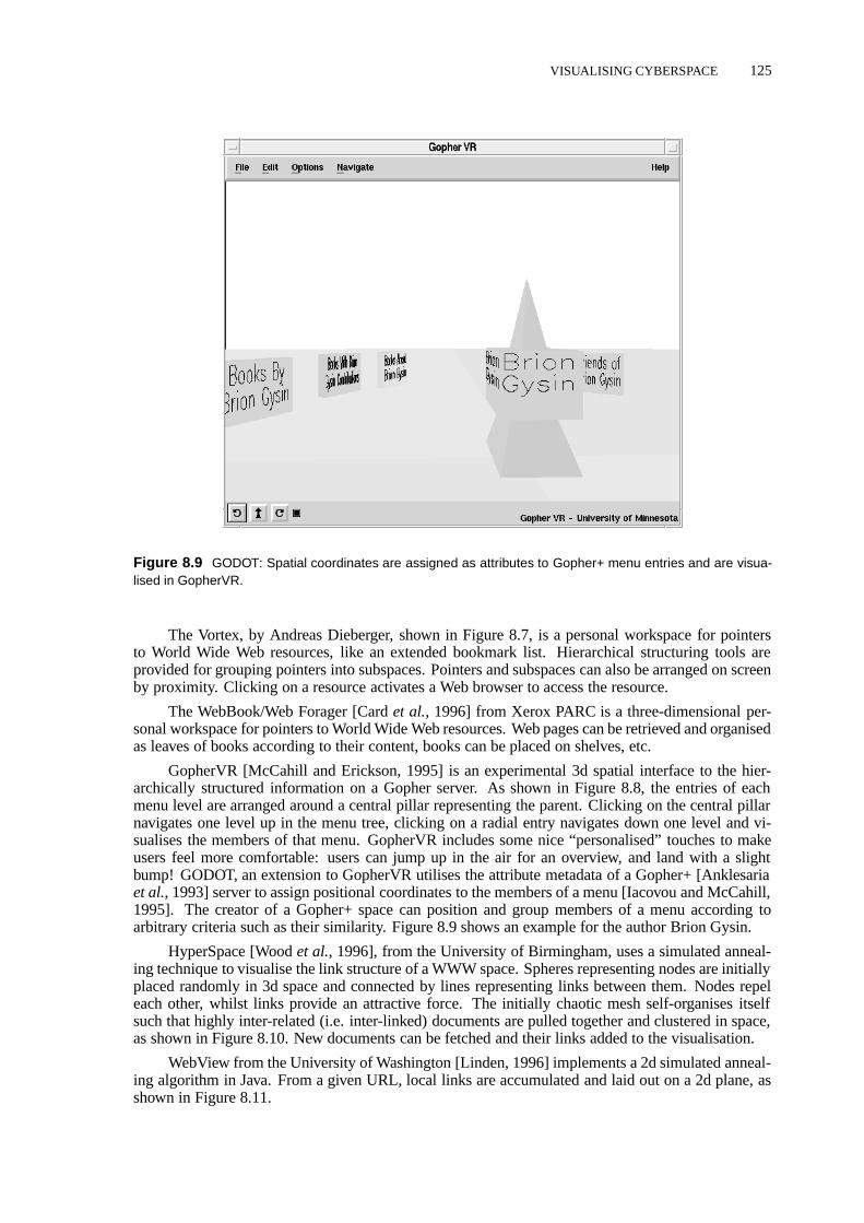
VISUALISING CYBERSPACE 125
Figure 8.9 GODOT: Spatial coordinates are assigned as attributes to Gopher+ menu entries and are visua-lised in GopherVR.
The Vortex, by Andreas Dieberger, shown in Figure 8.7, is a personal workspace for pointersto World Wide Web resources, like an extended bookmark list. Hierarchical structuring tools areprovided for grouping pointers into subspaces. Pointers and subspaces can also be arranged on screenby proximity. Clicking on a resource activates a Web browser to access the resource.
The WebBook/Web Forager [Cardet al., 1996] from Xerox PARC is a three-dimensional per-sonal workspace for pointers to World Wide Web resources. Web pages can be retrieved and organisedas leaves of books according to their content, books can be placed on shelves, etc.
GopherVR [McCahill and Erickson, 1995] is an experimental 3d spatial interface to the hier-archically structured information on a Gopher server. As shown in Figure 8.8, the entries of eachmenu level are arranged around a central pillar representing the parent. Clicking on the central pillarnavigates one level up in the menu tree, clicking on a radial entry navigates down one level and vi-sualises the members of that menu. GopherVR includes some nice “personalised” touches to makeusers feel more comfortable: users can jump up in the air for an overview, and land with a slightbump! GODOT, an extension to GopherVR utilises the attribute metadata of a Gopher+ [Anklesariaet al., 1993] server to assign positional coordinates to the members of a menu [Iacovou and McCahill,1995]. The creator of a Gopher+ space can position and group members of a menu according toarbitrary criteria such as their similarity. Figure 8.9 shows an example for the author Brion Gysin.
HyperSpace [Woodet al., 1996], from the University of Birmingham, uses a simulated anneal-ing technique to visualise the link structure of a WWW space. Spheres representing nodes are initiallyplaced randomly in 3d space and connected by lines representing links between them. Nodes repeleach other, whilst links provide an attractive force. The initially chaotic mesh self-organises itselfsuch that highly inter-related (i.e. inter-linked) documents are pulled together and clustered in space,as shown in Figure 8.10. New documents can be fetched and their links added to the visualisation.
WebView from the University of Washington [Linden, 1996] implements a 2d simulated anneal-ing algorithm in Java. From a given URL, local links are accumulated and laid out on a 2d plane, asshown in Figure 8.11.

126 VISUALISING CYBERSPACE IN HARMONY
Figure 8.10 HyperSpace: a self-organising 3d map of documents and links in a WWW space based onsimulated annealing. Copyright c 1995 Andy Wood, University of Birmingham, used with permission.
Figure 8.11 WebView: Java-based simulated annealing visualisation of WWW space. This is a map of GrazUniversity of Technology Computer Centre’s web site.

VISUALISING CYBERSPACE 127
Figure 8.12 MAPA: a Java-based visualisation of a hierarchical map of WWW space. The Web space here isthe Dynamic Diagrams web site.
MAPA from Dynamic Diagrams [Kahn, 1996] gathers link data from a Web site, and assemblesa synthetic hierarchy reflecting the editorial intention of the authors. The hierarchy is stored in adatabase and can be manually fine-tuned. A Java applet is used to display the hierarchical structurefrom within a Web browser, as depicted in Figure 8.12.
The Navigational View Builder [Mukherjea and Foley, 1995] uses a combination of link struc-ture analysis and manually assigned attributes (such as Author, Author-Type, Directory, Topic, andSubTopic) to cluster documents and form synthetic hierarchies. These then form the basis for visual-isations such as the cone tree diagram shown in Figure 8.13.
Taking an entirely different approach, Tim Bray used information contained in Open Text’srobot-generated index of about 1.5 million Web documents to generate dynamic visualisations inVRML of the biggest and most visible sites on the Web at the time [Bray, 1996], as shown in Fig-ure 8.14. Characteristics used to drive the visualisation include: the number of links pointing to a site(its visibility), the number of links pointing from a site (itsluminosity), and the number of pages a sitecontains (itssize).
The Internet Foyer, by the Communications Research Group (CRG) at the University of Notting-ham [Benfordet al., 1996], tracks the position of users on the CRG web site and creates a navigable,populated visualisation of the CRG home pages using the DIVE Collaborative Virtual Environment(CVE) platform [DIVE, 1996]. Nodes are modeled as spheres and hyperlinks as 3d arrows. Visitorsto the site are represented as 3d avatars. Figure 8.15 shows a view of (other) visitors in the foyer,gathered around the particular documents they are accessing. Visitors using a CVE client are ableto freely navigate the virtual foyer and interact (talk) with other CVE visitors. Visitors using a webbrowser see a series of flat projections of the foyer and a list of current visitors.
A particularly innovative feature is the integration of a real and virtual foyer in a “mixed reality”application. As can be seen in Figure 8.16, the virtual foyer is projected onto the wall of a realphysical foyer. At the same time, a camera transmits live video images from the physical foyer,which are represented as a texture map in the virtual environment. A microphone and speakers in the

128 VISUALISING CYBERSPACE IN HARMONY
Figure 8.13 The Navigational View Builder: A synthetic cone-tree style hierarchy map of a web site generatedby a combination of structure and attribute analysis. Copyright c 1995 Sougata Mukherjea, Georgia Institute ofTechnology, used with permission.
Figure 8.14 A visualisation of the biggest and most visible sites on the Web, using data in the Open Textrobot-generated index of the Web. Copyright c 1996 Tim Bray, Open Text Corporation, used with permission.
physical foyer complete the link-up between physical and virtual spaces. One of the consequences ofthis set-up is that members of the CRG canliterally watch as visitors browse their web pages!

VISUALISING CYBERSPACE 129
Figure 8.15 The Internet Foyer. A navigable, populated visualisation of a Web site, showing visitors to thesite as 3d avatars. Copyright c 1996 Communications Research Group, University of Nottingham, used withpermission.
Figure 8.16 The Internet Foyer is a “mixed reality” application, integrating a real and a virtual foyer. Copyrightc 1996 Communications Research Group, University of Nottingham, used with permission.

130 VISUALISING CYBERSPACE IN HARMONY
8.6 Hyper-G’s Rich Infrastructure for Visualisation
Three strategies have traditionally been employed to help users find their way in Internet informationspaces:
� A-priori organisation of information into hierarchies, like the table of contents of a book (andthe distinguishing feature of Gopher).
� Search facilities, like the index of a book (and typical of WAIS).
� Hyperlinks, like cross-references in a book (and embodied in the World-Wide Web).
The scope for visualisation of Gopher, WAIS, and WWW spaces is severely restricted by thelimitations of their respective data models. Visualisations, insofar as they have been provided at all,have necessarily treated each separately. Worse still there is little standardised meta-information,such as document type, size, owner, importance, etc., which can be bound to visual attributes of avisualisation.
Gopher supports a-priori organisation of information into hierarchies, and the most recent Go-pher protocol, Gopher+ [Anklesariaet al., 1993], supports both rich metadata attributes and HTMLdocuments (and hence to some degree hyperlinks), but Gopher+ is not widely implemented.
Looking specifically at the World-Wide Web, we find that on standard WWW servers, the hy-perlink is the only structuring facility available, leading to the “World Wide Spaghetti Bowl” (to quoteRobert Cailliau). Hierarchical structures can be simulated using menus of links, but such structurallinks are not readily distinguishable from standard associative links.
Moreover, most WWW servers do not make hyperlinks available separately, but store them em-bedded within documents, making the determination of back-links both difficult and time-consuming.Similarly, search facilities in WWW are not standardised. Search engines are typically bolted on toa standard Web server and their interfaces vary widely. To make things worse, the WWW currentlyprovides only a handful of standardised meta-data attributes such as document size, type/format, andmodification time1.
Thus, although techniques from information visualisation can be used to present graphicaloverviews of WWW information spaces, visualisations of the WWW today are, in general, limitedto maps of one-way hyperlinks, due to the lack of bidirectional links, additional structuring facilities,and standardised meta-information. Or as I put it in my talk [Andrews, 1996g] at the CHI’96 panelon Visualising the Internet[CHI96, 1996]: WWW lacks the “meat” to visualise.
Hyper-G, as described in Chapter 4, supports a-priori organisation of information into hier-archies, provides rich sets of standardised meta-data, and has a standard representation for searchresults. In addition, Hyper-G uses a separate link database for hyperlink facilities, has typed links,and has fully integrated search facilities. Only with such rich supporting infrastructure is it possibleto generate tightly-coupled, multi-faceted visualisations of information spaces. This leads to “Keith’sRecipe for Visualisation”:
(1) Provide the “meat”:
� Hierarchical structuring in collections.
� Standardised, integrated search facilities.
� Hyperlinks in separate link database.
� Rich metadata for documents, links, and collections.
(2) Cooktightly-coupledvisualisations of the first three.
(3) Flavour with attribute metadata.
1There is a proposed mechanism (the META tag) to include non-standard attributes in HTML documents. However, theavailability and naming of such tags varies widely from server to server.

THE HARMONY LOCAL MAP 131
Figure 8.17 The Harmony Local Map, showing UNIX manual pages within two links of the grep manual page.
8.7 The Harmony Local Map
Link maps have been attempted in numerous hypermedia systems. The accepted wisdom is that itis near impossible to visualise the entire space of hyperlink relationships for more than a few dozenlinks, and that local views around a particular document are very much more manageable and practicalto generate [Utting and Yankelovich, 1989].
Harmony’s Local Map is a graphical visualisation of relationships between objects in Hyper-G.By default, the Local Map generates a visualisation of an object’s immediate (referential) hyperlinkrelationships, i.e. other documents and objects one link away (both forward and backward) from thecurrent object, as was shown in Figure 5.21. Hyper-G’s links are stored in a separate link databaseand hence can be followed both forwards and backwards. Multiple levels of incoming and outgoinglinks can also be visualised, as can be seen in Figure 8.17.
Since links in Hyper-G are typed, the Local Map can filter links by type, for example: an-notations, inline images, and textures. Furthermore, the Harmony Local Map is able to representparent–child collection membership relationships, as an alternative representation to that of the col-lection browser. This is extremely useful when objects have more than one parent collection, as weshall see shortly.
In Hyper-G, hyperlinks always emanate from documents, but may point to either documents,collections or clusters. Since collections and clusters do not themselves have hyperlinks, the links ofthe collection head and the cluster members are visualised in the local map. Multiple links betweenthe same objects are collapsed down to a single edge in the local map. The map can be regenerated

132 VISUALISING CYBERSPACE IN HARMONY
Figure 8.18 Local map of inline image relationships.
Figure 8.19 Using the local map to determine where an inline image is used.
around any object by selecting (single-left-clicking) the object and issuing a Generate command,providing an alternate form of link navigation.
Double-left-clicking an object activates that object, for example retrieving and displaying adocument in the appropriate viewer. Single-clicking selects an object and activateslocation feedback,displaying the object’s location within the collection structure in the Session Manager’s collectionbrowser (see Section 5.5).
The Local Map can be used to visualise other kinds of relationships as well as referential hyper-links. Figure 8.18 shows a map of the inline images used in the cluster about the Graz Arsenal (seeFigure 5.5). Imagine you were considering editing the image “Armour 1” or replacing the image witha newer photograph, but wanted to know whether “Armour 1” is used elsewhere. Selecting “Armour1” and regenerating the Local Map shows the places where the image is used as an inline, in this caseonly in the English and German versions of the Arsenal text, as shown in Figure 8.19.
The Harmony Local Map has numerous options and settings, which can be configured in theOptions panel. These include the number and kind of incoming and outgoing relationships to bevisualised, the maximum number of objects in the map, and the spacing to be used in the layout.
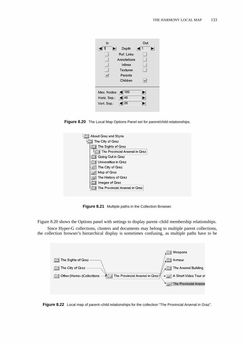
THE HARMONY LOCAL MAP 133
Figure 8.20 The Local Map Options Panel set for parent/child relationships.
Figure 8.21 Multiple paths in the Collection Browser.
Figure 8.20 shows the Options panel with settings to display parent–child membership relationships.
Since Hyper-G collections, clusters and documents may belong to multiple parent collections,the collection browser’s hierarchical display is sometimes confusing, as multiple paths have to be
Figure 8.22 Local map of parent–child relationships for the collection “The Provincial Arsenal in Graz”.

134 VISUALISING CYBERSPACE IN HARMONY
opened up to objects which belong to multiple parents. For example, in Figure 8.21, the collection“The Provincial Arsenal in Graz” belongs to both the collection “the City of Graz” and to its child“The Sights of Graz.” In such cases, the Local Map can be used effectively to display parent–childmembership relationships, in this case generating the map shown in Figure 8.22.
As a further helpful aid, both the Harmony Session Manager and the various document viewershave in-built shortcuts for generating local maps. For example, the document viewers have menuitems to generate a local map of References, Annotations, and Parents for the currently displayeddocument. The Harmony Text Viewer has a menu item to generate a map of the current text’s inlineimages, the Harmony VRweb VRML viewer has menu shortcuts to generate maps of a model’s inlinemodels and texture images, and so on.
8.8 The Harmony Information LandscapeThe Harmony Information Landscape is an interactive, three-dimensional visualisation of the Hyper-Gcollection structure, essentially a three-dimensional alternative to the traditional two-dimensional col-lection browser view shown in Figure 5.3. The Harmony Information Landscape is described in detailin [Eyl, 1995; Wolf, 1996]2. As illustrated in Figure 8.23 and Figure 8.24, the collection hierarchyis mapped out onto a plane, similar to the approach used by FSN to visualise a file system (FSNis described in Section 8.4). Flat blocks or pedestals represent collections and clusters, simple ab-stract icons atop these represent individual documents. The standard default mapping of documentattributes to visual representation is to encode document type through the shape of the corresponding3d icon, document size as the size of the icon, and use colour either to reinforce the document type orto convey the age of documents.
Users can fly over the landscape looking for salient features. The mouse buttons are used tocontrol the speed and direction of motion. Collections can be opened and closed and documentsaccessed through mouse clicks, menu commands, and keyboard shortcuts. As more collections areopened, the landscape fans out to accommodate them. The landscape’s Overview Map (top rightof Figure 8.24) provides both a sense of global context and orientation and an alternative form ofnavigation. Numerous settings can be configured interactively, including the colour coding used forcollections and documents, the logarithmic scaling factor applied to the size of the icons, and therelative sensitivity of the mouse.
Much of the functionality of the Harmony Session Manager (see Section 5.3) is also available inthe Information Landscape. Objects can be selected by single-left-clicking and activated by double-left-clicking. Middle-clicking a collection or document symbol flies the user gently to down to thatobject. Right-clicking brings up Harmony’s attribute window to display the object’s metadata.
The Information Landscape and the collection browser are synchronised, so that changes inone are automatically reflected in the other. Single-clicking an object in a search result list or inHarmony’s Local Map activates location feedback in both the collection browser and the informationlandscape: the path(s) to the object are opened up in both, giving users visual feedback about thecontext of an object’s use, its type, and its size, before any decision on whether to retrieve it. Locationfeedback in the landscape also results in the user being taken by the hand and gently flown to theselected object.
Unlike in FSN, where navigation is constrained to forward and backward motion, users are ableto navigate freely within the landscape, and may turn around and look back to view the parents ofa set of objects, as shown in Figure 8.25. The textual labels in the display are rotated and tilted asnecessary to match the user’s viewing position and angle.
A significant innovation of the Harmony Information Landscape is thecombineddisplay of bothhierarchical structuring and hyperlink relationships inonevisualisation, as depicted in Figure 8.26 forthe image document “Map of Graz”. Documents having links to this document are displayed beneaththe ground plane. Documents or collections reachable from the image are displayed above the ground
2The Harmony Information Landscape was implemented by Martin Eyl and Peter Wolf, under my supervision, in thecourse of their Master’s Theses.

THE HARMONY INFORMATION LANDSCAPE 135
Figure 8.23 The Harmony Information Landscape. Blocks on the plane represent collections and clusters.The default style represents various types of document with simple 3d icons.
Figure 8.24 Document clusters containing text and image documents. Note the overview window in the topright, the arrow indicating the user’s position and orientation.

136 VISUALISING CYBERSPACE IN HARMONY
Figure 8.25 Looking back to view the parents of a collection.
Figure 8.26 Superimposing hyperlink relationships upon the structure map. Links to and from the image “Mapof Graz” have been selected for display. Documents having links to this image are displayed on the lower plane.Documents or collections reachable from the image are displayed in the upper plane.

THE HARMONY INFORMATION LANDSCAPE 137
Figure 8.27 Arcs linking objects to their actual locations in the collection structure. Clicking an arc flies theuser gently down the path to the appropriate location.
plane. This combined visualisation, rather like having a Harmony Local Map overlaid in the verticalplane orthogonal to the landscape, utilises all three available dimensions to compactly present bothkinds of structure.
In analogy to Harmony’s Local Map, multiple levels of incoming and outgoing links may bedisplyed and the map is not limited to standard referential hyperlinks, but can selectively show onlyinline images, model textures, annotations, etc. It can also provide an orthogonal view of multipleparents, in cases where objects belong to more than one parent collection.
To provide further contextual feedback, a control button shows where the linked documents (inthe vertical plane) are actually located in the collection structure, by opening up paths to their positionin the main plane and drawing arcs to them, as can be seen in Figure 8.27. Clicking such an arc fliesthe user gently down the path to the appropriate location.
To achieve good performance across a wide range of platforms, the landscape is flat-shaded anddocuments are represented by simple abstract icons by default. However, unlike FSN, the icons areconfigurable and numerous other styles are available. Figure 8.28 shows the 3d icon chooser, throughwhich users can select icons to represent individual document types. Similar choosers are availableto select colours, fonts, line widths, etc.
Figure 8.29 illustrates the use of textured information landscapes. Thumbnail images pasted tonearby document icons to give an indication of their content. At the moment, a generic image is used,but in future a specific thumbnail image could be generated from an image document, or from thefirst (or a representative) frame of a film clip. Explicitly assigned keywords could be placed next to ormapped onto a document’s icon. For text documents, representative keywords could be automaticallyextracted from the document, possibly in conjunction with the server’s full text indexing. Currently,real-time texturing is only available for high-end graphics workstations, but as graphics hardware withtexture support becomes more widely available, this technology should also migrate down to desktopPCs.
As Kevin Lynch points out in his seminal work “The Image of the City” [Lynch, 1960],land-

138 VISUALISING CYBERSPACE IN HARMONY
Figure 8.28 A geometrically more complicated set of document icons and the 3d icon chooser (top right).
Figure 8.29 Textured information landscape. Thumbnail images pasted to nearby document icons give anindication of their content. “Landmark” 3d icons representing whole collections will be visible from afar.

FURTHER READING 139
marksplay an important role when people navigate a city. A future extension to the Harmony In-formation Landscape will allow authors to assign a “landmark” 3d icon to a collection, representingthe collection as a whole and visible from afar. For example a model of the Eiffel Tower might beassigned to represent a collection about Paris.
As with VRweb, Harmony’s 3d viewer described in Chapter 7, the Information Landscapecomes in two versions: a software-only version using the Mesa 3d library which runs on any UNIXplatform under X Windows and an OpenGL version which can take advantage of OpenGL hardwareacceleration, if available.
8.9 Further ReadingTwo good overviews of the field of information visualisation areVisualization’s New Tack: MakingSense of Information[Gershon and Eick, 1995b] andComputer Graphics and Visualization in theGlobal Information Infrastructure[Gershon and Brown, 1996].
The proceedings of the IEEE symposia on information visualisation [Gershon and Eick, 1995a;Gershon, 1996] are a source of detailed information on specific approaches.
An online starting point is Peter Young’s survey of three-dimensional information visualisation[Young, 1996].

140 VISUALISING CYBERSPACE IN HARMONY

9 Outlook
There is a saying that “an Internet year is like a dog year”: there are seven of them for each calendaryear, such is the pace of innovation and development. In this chapter, I take a look at the directionof current developments in the fields of Internet information systems, the World Wide Web, andinformation visualisation, I describe work in progress which I am directing, and outline some ideasfor future research.
9.1 General Trends
According to Jakob Nielsen’s analysis [Nielsen, 1996], 1993 was the Web year of glorified homepages, 1994 the year of content, 1995 the year offocussedcontent, and 1996 is the year of community-building, as web sites struggle to retain their audience. What will be the main Web trends in 1997?
My guess is that 1997 will be the year of the applet. Java is well on the way to displacing C++astheapplication programming language, and to establishing itself asthedownloadable, Internet ap-plication (applet) language. Java development tools, compilers, and virtual machine implementationsare progressing in leaps and bounds. Most Java applets around the Web today are of the tinker-toyvariety, but I believe we will see more and more powerful applets, capable of real, useful work gracingweb sites in 1997. Further ahead, Java “servlets”, or agents uploaded to a web server, will be able togarner information on your behalf.
By autumn 1996 we will see a number of VRML 2.0 browser implementations become availablefor all the major platforms, cementing VRML asthe3d modeling language. We might even see somereal, useful virtual worlds and applications modeled in VRML!
Microsoft is investing huge amounts of money in Internet products and development, and willcontinue to catch up on Netscape. I expect to see the market shares of Microsoft Internet Explorer andof Web servers running on Windows NT increase sharply. Apache will reinforce its position as thefree server of choice, as NCSA winds down development of its httpd server. Web server developmentis moving fast from a research field to an engineering task. Check out the Netcraft Web Server Survey[Netcraft, 1996] for the latest server statistics.
The trend in web tools will be towards information management tools. As smaller sites, “pow-ered by vi”, graduate to become larger sites, webmasters cannot fail to realise the necessity for suchtools (can they?).
As for the Internet itself, there are no signs of a slow-down in the increase in numbers of hostsand users. The new top-level domains [IANA, 1996] will relax pressure for.com domain names, butI expect IP address space will remain tight as IPng is slow in gaining acceptance.
Finally, I expect the emerging field of information visualisation to grow and crystalise further,especially since the Web is a vast information space just longing to be visualised.
9.2 Work in Progress
Of the work in progress which I am currently supervising, a suite of visualisation tools for Hyper-G,written as Java applets, is probably the most strategically important. Using Java, visualisation (andalso editing, structuring, and management) tools can be delivered to end-users’ Web browsers withoutthem having to explicitly install any additional software. In contrast, to gain the benefits of theadvanced navigation and visualisation tools in Harmony, users must first fetch and install the Harmony
141

142 OUTLOOK
distribution package. To use Java visualisation applets, they must do nothing more than wait until theapplets have been downloaded into the browser (which admittedly may take a non-negligible amountof time, depending on the size of the applet). Writing these tools in Java also means that they areplatform-independent and can be incorporated easily into a (future) Hyper-G client application writtenin Java. The visualisation applets currently being implemented include:
� A collection browser for navigating and editing Hyper-G’s collection structure.
� A local map to view the link and collection relationships around a specific object.
� A tree map view of the collection structure.
� A hyperbolic view of the collection structure.
� 2d and 3d views of search result sets, using clustering techniques from the field of informationretrieval.
We are also working on a new version of the VRweb VRML browser supporting VRML 2.0.To support the scripting facilities in VRML 2.0, it makes most sense to support Java as the scriptinglanguage and incrementally re-write part or all of VRweb in Java:
(1) We are starting with the user interface code, since that is the least portable part of the C++version.
(2) In parallel, we are writing a VRML 2.0 parser in Java (from scratch).
(3) Next, we will port the rest of the program logic to Java.
(4) Finally, once Java’s 3d API is available, we will move the 3d output as well.
The (current) performance of Java is certainly a concern, and we may need to keep some native codefor performance reasons, but the advantages of a VRML browser written entirely in Java, once Java’s3d API is ready and the interpreters and compilers are optimised, are persuasive:
� platform-independence,
� compilable as a native application for better performance, and
� downloadable as an applet when required.
As VRML models get larger and more ambitious and as people try to model whole cities, forexample, information management of complex models is starting to become an issue. Here, I seean ideal application for Hyper-G’s information management tools. By extracting texture links, inlinemodel links, and referential hyperlinks from a VRML model as it is inserted into a Hyper-G server(in the same way as for HTML text documents) and placing them in Hyper-G’s link database formanagement, large complex VRML models become much easier to handle. We are implementingexactly this facility at the moment.
Other work in progress includes:
� A home space builder and editing functionality for VRweb. Users can construct their own 3dworkspace complete with desk, shelves, and filing cabinets, within which to organise pointersto resources.
� An improved search interface for Harmony and a visualisation of search result sets.
� An improved version of the Harmony Audio player, with full hyperlink support, and a graphicaldisplay.

IDEAS FOR FUTURE WORK 143
� An instrumented version of Harmony which can log user interface actions for later analysis. Wewill ask a sample set of Harmony users to participate in an experiment and track their actionsover an extended period. Among other things, I hope that the experimental data will provideobjective evidence to help answer a question which has long interested me: do users prefer tonavigate by searching, by following hyperlinks, or by traversing a (collection) hierarchy?
One of the next projects I intend to undertake is a 3d visualisation of the structure of Hyper-Gservers based on generating VRML on the fly and/or using the promised Java3D API. The idea againis to bring the visualisation inside the Web browser.
9.3 Ideas for Future Work
The Harmony Information Landscape provides rich ground for further research and experimentation.As mentioned in Section 8.8, authors might be allowed to assign a “landmark” 3d icon to a collection,representing the collection as a whole and visible from afar. For example, a model of the Eiffel Towermight be assigned to represent a collection about Paris.
It would be desirable for users to be able to interactively configure the binding between informa-tion attributes and visualisation characteristics in the Harmony Information Landscape: for examplemapping age or price, rather than size in bytes, to the size of the corresponding document icon.
FSN [Tesler and Strasnick, 1992] allows users to set spatial bookmarks, like stakes in the ground,to which users can return at will in a single operation. These are equivalent to viewpoints in VRMLand should also probably be explored in the Harmony Information Landscape. An additional featurewould be the recording of a “flight path” for later playback; a guided tour which one could alsointerrupt and resume at any point.
An untapped source of information are usage statistics. Currently, the Hyper-G server logsaccesses in log files, but a minor modification to the server would enable a usage count to be kept foreach document and collection. This in turn would allow a document or collection’spopularity, i.e.number of accesses, to become a further candidate for mapping to visualisation characteristics. Thisidea could also be extended to hyperlink and collection navigation – popular links and paths becomethe main roads of a visualisation, less popular links are shown as side roads.
One could also consider assigning fixed coordinates to collections and visualising them in 3dspace, like having virtual real estate. This would allow users to incrementally build a mental mapof places and locations and navigate by visual memory. However, real estate management becomesa hard issue as soon as fixed coordinates are introduced, especially for very large and very dynamicinformation spaces. A slightly different approach would be to allow users to group and positionresources in a landscape themselves, in a kind of personal 3d workspace similar to the home spacebuilder described in Section 9.2 above.
The Hyper-G server is session-oriented and hence tracks which documents or collections parti-cular users are accessing. In other words, the Hyper-G server knows where users are and what theyare doing at any point of time. A promising use of this would be to visualise (other) users visitingnearby collections in the information landscape, similar to the Internet Foyer [Benfordet al., 1996]described in Section 8.5. Visitors to the same collection could be allowed to communicate with oneanother, through chat windows or audio channels, enabling virtual meeting places.
Taking this idea further, I see research promise in the area of collaborative shared spaces acrossthe Net, where virtual communities and project teams can meet and do work. These spaces might,but do not have to, have a three-dimensional rendering. As an application scenario, consider a virtualproject meeting where physically distributed team members can see each other’s avatars, can talk toone another, and can see and work on shared objects and documents.
Or as another example, consider two (or more) market analysts meeting in a space like theDiscovery Head Trader shown in Figure 8.4. One analyst turns a dial and says to the other some-thing like, “Look, if I increase the investment in this branch, we can expect to see returns over here

144 OUTLOOK
doubling...”. There are already a number of efforts in the direction of collaborative shared spaces, in-cluding NCSA’s Habanero project [NCSA, 1996a], Black Sun’s CyberHub [Black Sun, 1996], WorldsInc.’s Active Worlds and Gamma [Worlds Inc., 1996], and the University of Bonn’s MRTspace [Fell-ner and Jucknath, 1996].
Finally, a possible enhancement to Hyper-G which could bring rich returns would be to addsupport for workflow processes. In the workplace environment, a document typically undergoes manyrevisions, reviews, and changes of status in the course of its life. Formalising support for this kind ofprocess in Hyper-G would increase its attractiveness, particularly in the corporate intranet market.
10 Concluding Remarks
In this thesis I have presented my research work of the past five years in the field of navigation,construction, and visualisation of hypermedia on the Internet – the browsing, building, and beholdingof cyberspace.
Having begun the thesis with an introduction to the Internet and its services and informationsystems, I gave an overview of hypermedia systems. I then described the Hyper-G second-generationWeb server, which provides the supporting infrastructure and serves as the platform upon which tobase my work.
Chapters 5, 6, 7, and 8 of the thesis described my original work, embodied in the Harmonyclient and authoring tool for Hyper-G, for which I was project leader until the summer of 1995.The scientific and technical contribution of this work includes advanced browsing and navigationalfacilities, remote management and authoring tools, the first 3d Internet hypermedia browser, and twoinnovative information visualisation tools.
The thesis concluded with an analysis of current trends, an outline of work currently in progress,and some ideas for future research.
145

146 CONCLUDING REMARKS

Bibliography
Adobe (1996). Adobe SiteMill. http://www.adobe.com/prodindex/sitemill/main.html .
Adobe Systems Inc. (1990).PostScript Language Reference Manual, 2nd edition. Addison-Wesley,Reading, Mass.
AltaVista (1996).AltaVista. http://www.altavista.digital.com/ .Andreessen, M. (1993).NCSA Mosaic Technical Summary. ftp://ftp.ncsa.uiuc.edu/
Mosaic/Papers/mosaic.ps.Z .Andrews, K. (1992). Using 3D Scenes as Hypermedia Nodes. Poster at the ACM European
Conference on Hypertext (ECHT’92), Milan, Italy.Andrews, K. (1993a).Constructing Cyberspace: Virtual Reality and Hypermedia. Presented at
Virtual Reality Vienna ’93.ftp://ftp.iicm.edu/pub/Hyper-G/papers .Andrews, K. (1993b).ECHT’92 Conference Report. SIGLINK Newsletter, 2(1).Andrews, K. (1994). Spatial Metaphors for Information Systems. Workshop on Spatial User
Interface Metaphors in Hypermedia Systems, ACM European Conference on HypermediaTechnology (ECHT’94), Edinburgh, Scotland.http://www.gatech.edu/lcc/idt/Faculty/andreas dieberger/ECHT94.WS.Andrews.html .
Andrews, K. (1995a).Visualising Cyberspace: Information Visualisation in the Harmony InternetBrowser. In Proc. of First IEEE Symposium on Information Visualization (InfoVis’95), pages97–104, Atlanta, Georgia.
Andrews, K. (1995b).VRweb Project Announcement (Press Release). http://www.iicm.edu/vrweb-press-announce01.html .
Andrews, K. (1996a).Authoring with Harmony. In H. Maurer, editor,HyperWave: The NextGeneration Web Solution, Chapter 16, pages 345–376. Addison-Wesley.http://www.iicm.edu/hgbook .
Andrews, K. (1996b).Hypermedia Systems. In H. Maurer, editor,HyperWave: The Next Genera-tion Web Solution, Chapter 3, pages 19–29. Addison-Wesley.http://www.iicm.edu/hgbook .
Andrews, K. (1996c).HyperWave: The Next Generation Web Server. HyperWave course slides.http://www.iicm.edu/hgcourse .
Andrews, K. (1996d).Information Systems and the Internet. In H. Maurer, editor,HyperWave:The Next Generation Web Solution, Chapter 2, pages 9–18. Addison-Wesley.http://www.iicm.edu/hgbook .
Andrews, K. (1996e).Installing and Configuring Harmony. In H. Maurer, editor,HyperWave:The Next Generation Web Solution, Chapter 16, pages 235–242. Addison-Wesley.http://www.iicm.edu/hgbook .
Andrews, K. (1996f).Using Harmony. In H. Maurer, editor,HyperWave: The Next GenerationWeb Solution, Chapter 15, pages 193–234. Addison-Wesley.http://www.iicm.edu/hgbook .
Andrews, K. (1996g).Visualising the Internet: Where’s the Meat?Panel Presentation, CHI’96,Vancouver, Canada.
Andrews, K. and Kappe, F. (1993).Strait-Jacketing Authors: User Interface Consistency in Large-Scale Hypermedia Systems. In Proc. Hypermedia ’93, Zurich, Switzerland, pages 130–137,Berlin. Springer.
Andrews, K. and Kappe, F. (1994).Soaring Through Hyperspace: A Snapshot of Hyper-G and itsHarmony Client. In W. Herzner and F. Kappe, editors,Proc. of Eurographics Symposium on
147

148 BIBLIOGRAPHY
Multimedia/Hypermedia in Open Distributed Environments, pages 181–191, Graz, Austria.Springer.
Andrews, K. and Kappe, F. (1995).Using the Hyper-G Authoring Environment to Create WebInformation. In Poster Proceedings, Third International World-Wide Web Conference,WWW’95, Darmstadt, Germany, pages 99–102.
Andrews, K. and Pichler, M. (1994).Hooking Up 3-Space: Three-Dimensional Models as Fully-Fledged Hypermedia Documents. In Proc. of East-West International Conference on Multi-media, Hypermedia, and Virtual Reality (MHVR’94), pages 11–18, Moscow, Russia.
Andrews, K. and Pichler, M. (1996).Hooking Up 3-Space: Three-Dimensional Models as Fully-Fledged Hypermedia Documents. In Multimedia, Hypermedia, and Virtual Reality, number1077 in LNCS, pages 28–44. Springer.
Andrews, K., Kappe, F. and Schipflinger, J. (1994a).Harmony: A Tool for Navigating ThroughDeep Hyperspace. In Proc. of ED-MEDIA 94, page 627, Vancouver, Canada. AACE.
Andrews, K., Maurer, H. and Scherbakov, N. (1994b).Object-Oriented Data Modeling in Hy-permedia: A New Data Model. In Proc. of ED-MEDIA 94, page 703, Vancouver, Canada.AACE. Poster and Demo.
Andrews, K., Nedoumov, A. and Scherbakov, N. (1995a).Embedding Courseware Into Internet:Problems and Solutions. In Proc. of ED-MEDIA 95, pages 75–80, Graz, Austria. AACE.http://www.iicm.edu/edmedia papers ps .
Andrews, K., Kappe, F. and Maurer, H. (1995b).Hyper-G and Harmony: Towards the Next Gen-eration of Networked Information Technology. In Formal Demonstration, CHI’95 Confer-ence Companion, pages 33–34, Denver, Colorado.http://www.acm.org/sigchi/chi95/Electronic/documnts/demos/ka bdy.htm .
Andrews, K., Kappe, F. and Maurer, H. (1995c).Hyper-G: Towards the Next Generation of Net-work Information Technology. Journal of Universal Computer Science, 1(4), 206–220. Spe-cial Issue: Selected Proceedings of the Workshop on Distributed Multimedia Systems, Graz,Austria, Nov. 1994.http://www.iicm.edu/jucs .
Andrews, K., Kappe, F. and Maurer, H. (1995d).Hyper-G: Towards the Next Generation of Net-work Information Technology. Journal of Universal Computer Science, 1(4), 206–220. Spe-cial Issue: Selected Proceedings of the Workshop on Distributed Multimedia Systems, Graz,Austria, Nov. 1994.http://www.iicm.edu/jucs .
Andrews, K., Kappe, F., Maurer, H. and Schmaranz, K. (1995e).On Second Generation Net-work Hypermedia Systems. In Proc. of ED-MEDIA 95, pages 69–74, Graz, Austria. AACE.http://www.iicm.edu/edmedia papers ps .
Andrews, K., Maurer, H. and Scherbakov, N. (1995f).Semantic Modeling of Object-OrientedHypermedia Databases. In Proc. of Fifth International Conference on Human-ComputerInteraction (EWHCI’95), pages 121–134, Moscow, Russia. Springer LNCS 1015.
Andrews, K., Kappe, F. and Maurer, H. (1995g).Serving Information to the Web with Hyper-G.Computer Networks and ISDN Systems, 27(6), 919–926. Proc. Third International World-Wide Web Conference, WWW’95, Darmstadt, Germany.http://www.igd.fhg.de/www/www95/proceedings/papers/105/hgw3.html .
Andrews, K., Pichler, M. and Wolf, P. (1996).Towards Rich Information Landscapes for Visuali-sing Structured Web Spaces. In Proc. of 2nd IEEE Symposium on Information Visualization(InfoVis’96), San Francisco, CA.
Anklesaria, F., Lindner, P., McCahill, M., Torrey, D., Johnson, D. and Alberti, B. (1993).Gopher+:Upward Compatible Enhancements to the Internet Gopher Protocol. ftp://boombox.micro.umn.edu/pub/gopher/gopher protocol/Gopher+/Gopher+.txt .
Apache (1996).The Apache HTTP Server Project. http://www.apache.org/ .Asymetrix Corporation (1989).Using ToolBook. A Guide to Building and Working with Books.
Asymetrix Corporation, Bellevue, Washington.Aubrey, D. (1996). Hyper-G, the new networking hypermedia system, adds new depth to Web

BIBLIOGRAPHY 149
searches. Computer Shopper, pages 579–588.http://www.zdnet.com/cshopper/ .Begeman, M. L. and Conklin, J. (1988).The Right Tool for the Job. Byte, 13(10), 255–266.Bell, G., Parisi, A. and Pesce, M. (1995).The Virtual Reality Modeling Language – Version 1.0
Specification. http://vrml.wired.com/vrml.tech/vrml10-3.html .Bell, G., Parisi, A. and Pesce, M. (1996a).The Virtual Reality Modeling Language – Version 1.0C
Specification. http://vag.vrml.org/vrml10c.html .Bell, G., Carey, R. and Marrin, C. (1996b).The Virtual Reality Modeling Language Specification,
Version 2.0. http://vag.vrml.org/VRML2.0/FINAL/ .Benford, S., Brown, C., Reynard, G. and Greenhalgh, C. (1996).The Internet Foyer. University of
Nottingham. http://www.crg.cs.nott.ac.uk/Foyer/foyer.html .Berk, E. and Devlin, J., editors (1991).Hypertext/Hypermedia Handbook. Software Engineering
Series. McGraw-Hill, New York.Berners-Lee, T. and Conolly, D. (1993).HyperText Markup Language (HTML). http://www.
w3.org/pub/WWW/Markup/Markup.html .Berners-Lee, T., Cailliau, R., Luotonen, A., Nielsen, H. F. and Secret, A. (1994).The World-Wide
Web. Communications of the ACM, 37(8), 76–82.Black Sun (1996).CyberHub. Black Sun Interactive, Inc.http://www.blacksun.com/ .Bradley, J. (1996).XV. ftp://ftp.cis.upenn.edu/pub/xv/ .Bray, T. (1996).Measuring the Web. Computer Networks and ISDN Systems, 28(7–11), 993–1005.
Proc. Fifth International World-Wide Web Conference, WWW5, Paris, France.http://www5conf.inria.fr/fich html/papers/P9/Overview.html .
Brown, P. J. (1992).UNIX Guide: lessons from ten years’ development. In Proc. ECHT’92, pages63–70, Milan, Italy. ACM Press.
Buford-Koegel, J., editor (1994).Multimedia Systems. ACM Press.Bush, V. (1945). As We May Think. The Atlantic Monthly, 176(1), 101–108. Reprinted in
“CD-ROM — The New Papyrus”, Microsoft Press, 1986.http://www.isg.sfu.ca/~duchier/misc/vbush/vbush.shtml .
Cailliau, R. (1995).About WWW. Journal of Universal Computer Science, 1(4), 221–231. Spe-cial Issue: Selected Proceedings of the Workshop on Distributed Multimedia Systems, Graz,Austria, Nov. 1994.http://www.iicm.edu/jucs .
Canter, D., Rivers, R. and Storrs, G. (1985).Characterizing User Navigation Through ComplexData Structures. Behaviour and Information Technology, 4(2), 93–102.
Card, S. K., Robertson, G. G. and Mackinlay, J. D. (1991).The Information Visualiser, An Infor-mation Workspace. In Proc. CHI’91: Human Factors in Computing Systems, pages 181–188,New Orleans, Louisiana. ACM.
Card, S. K., Robertson, G. G. and York, W. (1996).The WebBook and the Web Forager: An Infor-mation Workspace for the World Wide Web. In Proc. CHI’96: Human Factors in ComputingSystems, pages 111–117, Vancouver, Canada. ACM.
CHI96 (1996). Visualising the Internet: Putting the User in the Driver’s Seat. In Panel, CHI’96Conference Companion, pages 163–164, Vancouver, Canada.
CNIDR (1994). freeWAIS 0.3. Clearinghouse for Networked Information Dis-covery and Retrieval (CNIDR). ftp://ftp.cnidr.org/pub/NIDR.tools/freeWAIS-0.3.tar.gz .
Conklin, J. (1987).Hypertext: An Introduction and Survey. IEEE Computer, 20(9), 17–41.Conklin, J. and Begeman, M. L. (1988).gIBIS: A Hypertext Tool for Exploratory Policy Discus-
sion. ACM Transactions on Office Information Systems, 6(4), 303–331.Dalitz, W. and Heyer, G. (1996).HyperWave: The New Generation Internet Information Sys-
tem Based on Hyper-G Technology. dpunkt. http://www.dpunkt.de/produkte/Hyperwave.html .
December, J. (1996). Internet Tools Summary. http://www.rpi.edu/Internet/

150 BIBLIOGRAPHY
Guides/decemj/itools/internet-tools.html .Dewan, P. (1993).A Survey of Applications of CSCW Including Some in Educational Settings. In
Proc. ED-MEDIA 93, Orlando, Florida, pages 147–152, Charlottesville, VA. AACE.DIVE (1996). The Distributed Interactive Virtual Environment. Swedish Institute of Computer
Science (SICS).http://www.sics.se/dive/ .Domik, G. (1991).The Role of Visualization in Understanding Data. In H. Maurer, editor,New
Results and New Trends in Computer Science, pages 91–107, Graz, Austria. Springer LNCS555.
Duncan, R. (1990).An introduction to building applications with ToolBook. PC Magazine, 9(21),493–497.
Edwards, D. M. and Hardman, L. (1989).Lost in Hyperspace: Cognitive Mapping and Navigationin a Hypertext Environment. In R. McAleese, editor,Hypertext: Theory into Practice, pages105–125. Blackwell Scientific Publications, Ablex.
EFF (1996). Internet Guide. Available from Electronic Frontier Foundation athttp://www.eff.org or http://www.iicm.edu/internet guide .
Emtage, A. and Deutsch, P. (1992).Archie – An Electronic Directory Service for the Internet. InUSENIX Winter 1992 Technical Conference Proceedings, pages 93–110, San Francisco, CA.USENIX Association.
Engelbart, D. C. (1988).The Augmented Knowledge Workshop. In A. Goldberg, editor,A Historyof Personal Workstations, pages 187–236. ACM Press.
Eubanks, C., McKeon, R., Nadeau, D. and Moreland, J. (1996).VRML Repository. San DiegoSupercomputer Center.http://www.sdsc.edu/vrml/ .
Eyl, M. (1995).The Harmony Information Landscape: Interactive, Three-Dimensional NavigationThrough an Information Space. Master’s thesis, Graz University of Technology, Austria.ftp://ftp.iicm.edu/pub/Hyper-G/doc/eyl.ps.gz .
Fairchild, K. M., Poltrock, S. E. and Furnas, G. W. (1988).SemNet: Three-Dimensional Rep-resentations of Large Knowledge Bases. In R. Guindon, editor,Cognitive Science and itsApplications for Human-Computer Interaction, pages 201–233. Lawrence Erlbaum, Hills-dale, New Jersey.
Fairchild, K. M., Serra, L., Hern, N., Hai, L. B. and Leong, A. T. (1993).Dynamic FishEyeInformation Visualizations. In R. A. Earnshaw, M. A. Gigante, and H. Jones, editors,VirtualReality Systems, pages 161–177. Academic Press.
Fellner, D. (1996). 3D-CGI. http://hyperg.cs.uni-bonn.de/CompGraph.ResearchProjects.CGI-3D .
Fellner, D. W. and Jucknath, O. (1996).MRTspace: Multi-User 3D Environments using VRML. InProc. WebNet’96, San Francisco, California.
Filippini, L. (1996). Moving Picture Expert Group MPEG Home Page. http://www.crs4.it/HTML/LUIGI/MPEG/ .
Flohr, U. (1995).Hyper-G Organizes the Web. BYTE, pages 59–64.http://www.byte.com/art/9511/sec5/art4.htm .
Flynn, P. (1995).The World Wide Web Handbook. International Thomson Computer Press, Lon-don.
Foley, J. D., van Dam, A., Feiner, S. K. and Hughes, J. F. (1990).Computer Graphics: Principlesand Practice, second edition. Addison-Wesley, Reading, Massachusetts.
Foss, C. (1988).Effective Browsing in Hypertext Systems. In Proc. RIAO’88, pages 82–98, Cam-bridge, Massachusetts. MIT.
Fulton, J. and Renda, G. (1994).The Network Audio System. ftp://ftp.x.org/contrib/audio/nas/xcon94paper.ps.gz .
Gershon, N., editor (1996).Proc. of Second IEEE Symposium on Information Visualization (Info-Vis’96), San Francisco, California. IEEE Computer Society Press.

BIBLIOGRAPHY 151
Gershon, N. and Brown, J. R. (1996).Computer Graphics and Visualization in the Global Infor-mation Infrastructure. IEEE Computer Graphics and Applications, 16(2), 60–75.
Gershon, N. and Eick, S. G., editors (1995a).Proc. of First IEEE Symposium on InformationVisualization (InfoVis’95), Atlanta, Georgia. IEEE Computer Society Press.
Gershon, N. and Eick, S. G. (1995b).Visualization’s New Tack: Making Sense of Information.IEEE Spectrum, pages 38–56.
Gibson, W. (1984).Neuromancer. ACE Books, Berkley Publishing Group, New York.Goodman, D. (1987).The Complete HyperCard Handbook. Bantam, New York.Haan, B. J., Kahn, P., Riley, V. A., Coombs, J. H. and Meyrowitz, N. K. (1992).IRIS Hypermedia
Services. Communications of the ACM, 35(1), 36–51.Halasz, F. G. (1988).Reflections on NoteCards: Seven Issues for the Next Generation of Hyper-
media Systems. Communications of the ACM, 31(7), 836–852.Hall, W., Davis, H. and Hutchings, G. (1996).Rethinking Hypermedia: The Microcosm Approach.
Kluwer.Hill, F. S. (1990).Computer Graphics. MacMillan.Iacovou, N. and McCahill, M. P. (1995).GODOT: GopherVR Organized Directories of Titles.
In Proc. of CIKM ’95 Workshop on New Paradigms in Information Visualization and Ma-nipulation, Baltimore, Maryland. ACM.http://www.cs.umbc.edu/ ~cikm/1995/npiv/ .
IANA (1996). New Registries and Domains. http://www.iana.org/iana/registries.html .
INRIA/GRIF (1996).Symposia. http://symposia.inria.fr/ .ISOC (1996).Internet Society. http://info.isoc.org/ .JavaSoft (1996).JavaSoft. http://java.sun.com/ .Johnson, B. and Shneiderman, B. (1991).Tree-Maps: A Space-Filling Approach to the Visual-
ization of Hierarchical Information Structures. In Proc. IEEE Visualization ’91, San Diego,California, pages 284–291, Los Alamitos, California. IEEE Computer Society Press.
Kahle, B., Morris, H., Davis, F., Tiene, K., Hart, C. and Palmer, R. (1992).Wide Area InformationServers: An Executive Information System for Unstructured Files. Electronic Networking:Research, Applications and Policy, 2(1), 59–68.
Kahn, P. (1996). MAPA Mapping Web Sites. Dynamic Diagrams. http://DynamicDiagrams.com/services map main.html .
Kappe, F. (1991). Aspects of a Modern Multi-Media Information System. Ph.D. thesis, GrazUniversity of Technology, Austria.ftp://ftp.iicm.edu/pub/Hyper-G/papers/report308.ps.gz .
Kappe, F. (1993).Hyper-G: A Distributed Hypermedia System. In B. Leiner, editor,Proc. INET’93, San Francisco, California, pages DCC–1–DCC–9. Internet Society.
Kappe, F. (1995a).Hyper-G Interchange Format (HIF): Version 1.0. http://www.iicm.edu/hif .
Kappe, F. (1995b). Hyper-G Text Format (HTF): Version 2.12. Technical report, IICM,Graz University of Technology. ftp://ftp.iicm.edu/pub/Hyper-G/papers/htf-212.ps.gz .
Kappe, F. (1995c).A Scalable Architecture for Maintaining Referential Integrity in DistributedInformation Systems. Journal of Universal Computer Science, 1(2), 84–104. Available athttp://www.iicm.edu/jucs .
Kappe, F. and Maurer, H. (1993).From Hypertext to Active Communication/Information Systems.IIG Report 363, IIG, Graz University of Technology, Austria.ftp://ftp.iicm.edu/pub/Hyper-G/doc/ .
Kappe, F. and Pani, G. (1994).Hyper-G Client/Server Protocol (HG-CSP): Version 7.05.Technical report, IICM, Graz University of Technology. ftp://ftp.iicm.edu/

152 BIBLIOGRAPHY
pub/Hyper-G/papers/HG-CSP-7.05.ps.gz .Kappe, F., Andrews, K., Faschingbauer, J., Gaisbauer, M., Pichler, M. and Schipflinger, J. (1994).
Hyper-G: A New Tool for Distributed Hypermedia. In Proc. Distributed Multimedia Systemsand Applications, pages 209–214, Honolulu, Hawaii. IASTED/ISSM, ACTA Press, ISBN:0-88986-194-3.
Krol, E. (1994). The Whole Internet: User’s Guide and Catalog, second edition. O’Reilly &Associates.
Laky, G. (1993).Usability Evaluation ausgesuchter Interface Parameter eines gro¨sen Hypermedi-asystems anhand eines ToolBook Prototyps. Master’s thesis, Graz University of Technology,A-8010 Graz, Austria. In German.
Lamping, J., Rao, R. and Pirolli, P. (1995).A Focus+Context Technique Based on HyperbolicGeometry for Visualizing Large Hierarchies. In Proc. CHI’95, Denver, Colorado, pages401–408. ACM.
Leberl, F., Andrews, K. and Helmut M¨ulner (1993).Graphical, Visual, and Immersive Interactionwith Geographic Data. In Proc. UDMS’93, Vienna, Austria, pages 1–10, A-1010 Vienna,Austria. ADV.
Levitt, J. (1996).Managing Your Web Site. InformationWeek. http://techweb.cmp.com/iw/567/67olweb.htm .
Lightscape (1996).Lightscape Visualization System. Lightscape Technologies, Inc.http://www.lightscape.com/ .
Linden, G. (1996). WebView: A new way to search and view pages on the World Wide Web!University of Washington.http://www.cs.washington.edu/homes/glinden/WebView/WebView.html .
Lindner, P. (1995). Using Gopher with the World-Wide-Web. gopher://boombox.micro.umn.edu/00/gopher/Gopher Conference 95/Papers/WebbedGopher .
Linton, M. A., Vlissides, J. M. and Calder, P. R. (1989).Composing User Interfaces with Inter-Views. IEEE Computer, 22(2), 8–22.
Lippman, A. (1980).Movie-Maps: An Application of the Optical Videodisc to Computer Graphics.Computer Graphics, 14(3), 32–42.
Lougher, P. (1996).mpegUtil. http://www.comp.lancs.ac.uk/computing/users/phillip/mpegUtil.html .
Lycos (1996).Lycos, Inc.http://www.lycos.com/ .Lynch, D. C. and Rose, M. T., editors (1993).Internet System Handbook. Addison-Wesley.Lynch, K. (1960).The Image of the City. MIT Press, Cambridge, Massachusetts.Mackinlay, J. D. (1986).Automating the Design of Graphical Presentations of Relational Infor-
mation. ACM Transactions on Graphics, 5(2), 110–141.Mackinlay, J. D., Card, S. K. and Robertson, G. G. (1990).Rapid Controlled Movement Through
a Virtual 3D Workspace. In Proc. SIGGRAPH ’90, Dallas, Texas, pages 171–176, New York.ACM.
Mackinlay, J. D., Robertson, G. G. and Card, S. K. (1991).The Perspective Wall: Detail andContext Smoothly Integrated. In Proc. CHI’91, New Orleans, Louisiana, pages 173–179,New York. ACM.
Maurer, H., editor (1996).HyperWave: The Next Generation Web Solution. Addison-Wesley.http://www.iicm.edu/hgbook .
Maurer, H. and Scherbakov, N. (1996).Multimedia Authoring for Presentation and Education.The Official Guide to HM Card. Addison-Wesley.
Maurer, H. and Schmaranz, K. (1994).J.UCS — The Next Generation in Electronic JournalPublishing. Computer Networks for Research in Europe, 26, S63–S69. Supplement to Vol.26 of Computer Networks and ISDN Systems.

BIBLIOGRAPHY 153
Maurer, H., Philpott, A. and Sherbakov, N. (1994a).Hypermedia Systems without Links. Journalof Microcomputer Applications, 17(4).
Maurer, H., Scherbakov, N., Andrews, K. and Parthasarathy, S. (1994b).Object-oriented mod-elling of hyperstructure: overcoming the static link deficiency. Information and SoftwareTechnology, 36(6), 315–322.
Maurer, H., Scherbakov, N. and Andrews, K. (1996).Browsing Hypermedia Composites: AnAlgebraic Approach. In Proc. of WebNet’96, San Francisco, CA.
Mayrhofer, V. and Andrews, K. (1996).Harmony User Guide: Version 1.4. ftp://ftp.iicm.edu/pub/Hyper-G/papers/hug.ps.gz .
McAleese, R. (1989).Navigation and Browsing in Hypertext. In R. McAleese, editor,Hypertext:Theory into Practice, pages 6–44. Blackwell Scientific Publications, Ablex.
McCahill, M. P. and Anklesaria, F. X. (1995).Evolution of Internet Gopher. Journal of UniversalComputer Science, 1(4), 235–246. Selected Proceedings of the Workshop on DistributedMultimedia Systems, Graz, Austria, Nov. 1994.http://www.iicm.edu/jucs .
McCahill, M. P. and Erickson, T. (1995).Design for a 3D Spatial User Interface for InternetGopher. In Proc. of ED-MEDIA 95, pages 39–44, Graz, Austria. AACE.http://www.iicm.edu/edmedia papers ps .
Meckler (1996).Mecklermedia Internet World. http://www.iw.com/ .Medienhaus Styria (1996).Kleine Online. http://www.styria.co.at/kleine .Memex (1996). Memex and Beyond Web Site. http://www.cs.brown.edu/memex/
home.html .Merit NIC (1996). NSFNET Backbone Statistics. ftp://nic.merit.edu/nsfnet/
statistics .Microsoft (1996). Internet Information Server. http://www.microsoft.com/
industry/sap/iis/iis.htm .Microsoft (1996). Microsoft FrontPage. http://www.microsoft.com/msoffice/
frontpage/ .Microsoft (1996). Microsoft Internet Explorer. http://www.microsoft.com/ie/
ie.htm .Microsoft (1995). Microsoft Unveils Wide-Ranging Commitment to Internet. http://www.
microsoft.com/corpinfo/press/1995/95dec/iswpr4.htm .Mukherjea, S. and Foley, J. D. (1995).Visualizing the World-Wide Web with the Navigational
View Builder. Computer Networks and ISDN Systems, 27(6), 1075–1087. Proc. Third In-ternational World-Wide Web Conference, WWW’95, Darmstadt, Germany.http://www.igd.fhg.de/www/www95/proceedings/papers/44/mukh/mukh.html .
Murray, J. D. and van Ryper, W. (1996).Encyclopedia of Graphics File Formats, second edition.O’Reilly & Associates.
Musciano, C. and Kennedy, B. (1996).HTML: The Definitive Guide. O’Reilly & Associates.NCSA (1996a).NCSA Habanero Project Overview. http://www.ncsa.uiuc.edu/SDG/
Software/Habanero/ .NCSA (1996b).The NCSA HTTPd Home Page. http://hoohoo.ncsa.uiuc.edu/ .Neider, J., Davis, T. and Woo, M. (1993).OpenGL Programming Guide. Addison-Wesley.Nelson, T. H. (1965).A File Structure for the Complex, the Changing, and the Indeterminate. In
Proc.20th ACM National Conference, pages 84–100.Nelson, T. H. (1987).Computer Lib/Dream Machines, revised edition. Tempus/Microsoft Press.Nelson, T. H. (1993).Literary Machines, 93.1 edition. Mindful Press, 3020 Bridgeway Suite
295, Sausalito CA 94965. Available fromhttp://www.eastgate.com/products/Cat Books.html .
Netcraft (1996). The Netcraft Web Server Survey. http://www.netcraft.co.uk/Survey/ .

154 BIBLIOGRAPHY
Netscape (1996).Netscape Communications Corporation. http://home.netscape.com/ .Netscape (1996). Netscape LiveWire. http://home.netscape.com/comprod/
products/tools/livewire datasheet.html .Netscape (1996). Netscape Navigator. http://home.netscape.com/comprod/
products/navigator/ .Network Wizards (1996). Internet Domain Survey. http://www.nw.com/zone/WWW/
top.html .Nielsen, J. (1995).Multimedia and Hypertext: The Internet and Beyond. Academic Press, San
Diego, California.Nielsen, J. (1996).Relationships on the Web. The Alert Box. http://www.sun.com/-
960101/columns/alertbox/ .Niemeyer, P. and Peck, J. (1996).Exploring Java. O’Reilly & Associates. http://
www.ora.com/catalog/expjava/ .OpenGL Architecture Review Board (1992).OpenGL Reference Manual. Addison-Wesley.Orasche, G., Pichler, M. and Andrews, K. (1995).Viewing VRML Scenes with VRweb. In
D. Fellner, editor,Modeling – Virtual Worlds – Distributed Graphics, Proc. of MVD’95,pages 179–189, Bonn, Germany. infix, D-53757 Sankt Augustin.http://hyperg.cs.uni-bonn.de/GI411.events.contrib.ws1195.Orasche .
Paul, B. (1996). The Mesa 3-D Graphics Library. http://www.ssec.wisc.edu/~brianp/Mesa.html , Space Science and Engineering Center, University of Wisconsin.
Pesce, M. (1995).VRML: Browsing and Building Cyberspace. New Riders/Macmillan.Pichler, M. (1993).Interactive Browsing of 3D Scenes in Hypermedia: The Hyper-G 3D Viewer.
Master’s thesis, Graz University of Technology, Austria.ftp://ftp.iicm.edu/pub/Hyper-G/doc/pichler1.ps.gz .
Pichler, M., Orasche, G., Andrews, K., Grossman, E. and McCahill, M. (1995).VRweb: A Multi-System VRML Viewer. In Proc. First Annual Symposium on the Virtual Reality ModelingLanguage (VRML ’95), pages 77–85, San Diego, California.
PLACE (1996).The PLACE Language. http://www.iicm.edu/wm doc/place .Planet9 (1996).VirtualSOMA. Planet 9 Studios.http://www.hyperion.com/planet9/
vrsoma.htm .Poskanzer, J. (1996).PBMPLUS: Portable Bitmap Utilities. ftp://ftp.x.org/ .Quittner, J. (1994). Billions Registered. Wired, 2(10). http://www.hotwired.com/
wired/2.10/departments/electrosphere/mcdonalds.html .Raggett, D. (1994).Extending WWW to Support Platform Independent Virtual Reality. In Proc.
INET’94, pages 242–1–6, Prague. Internet Society.http://info.isoc.org/isoc/whatis/conferences/inet/94/proceedings/242.ps .
Reisinger, B. and Faschingbauer, J. (1996).The Hyper-G Gateway Interface (HGI). http://www.iicm.edu/HGI .
Robertson, G. G., Mackinlay, J. D. and Card, S. K. (1991).Cone Trees: Animated 3D Visualiza-tions of Hierarchical Information. In Proc. CHI’91, New Orleans, Louisiana, pages 189–194,New York. ACM.
Robertson, G. G., Card, S. K. and Mackinlay, J. D. (1993).Information Visualization Using 3DInteractive Animation. Communications of the ACM, 36(4), 56–71.
Salton, G. (1989). Automatic Text Processing. Series in Computer Science. Addison-Wesley,Reading, MA.
Sams (1995).The Internet Unleashed, 2nd edition. Sams.net Publishing.Savetz, K. (1996). The Unofficial Internet Book List. http://www.northcoast.com/
savetz/booklist/ .Sengstack, J. (1996).Hyper-G: The Next Generation Web Server? New Media, pages 19–20.
http://www.hyperstand.com/ .

BIBLIOGRAPHY 155
Serra, L., Chua, T.-S. and Teh, W.-S. (1991).A Model for Integrating Multimedia InformationAround 3D Graphics Hierarchies. The Visual Computer, 7(5-6), 326–343.
Shneiderman, B. (1996).The Eyes Have It: A Task by Data Type Taxonomy for InformationVisualizations. In Proc. 1996 IEEE Symposium on Visual Languages, Boulder, Colorado.IEEE Computer Society.ftp://ftp.cs.umd.edu/pub/papers/papers/3665/3665.ps.Z .
SIGLINK (1996). ACM SIGLINK Home Page. http://www.acm.org/siglink/ .Smith, P. A. and Wilson, J. R. (1993).Navigating in Hypertext Through Virtual Environments.
Applied Ergonomics, 24(4), 271–278. Butterworth-Heinemann Ltd.Stochniol, A. (1996). asWedit. ftp://sunsite.doc.ic.ac.uk/packages/www/
asWedit/ .Strasnick, S. L. and Tesler, J. D. (1996).Method and Apparatus for Displaying Data within
a Three-Dimensional Information Landscape. Silicon Graphics, Inc. US Patent number5,528,735. Filed 23rd March 1993, granted 18th June 1996. Available from the US Patentand Trademark Officehttp://www.uspto.gov/ .
Stroustrup, B. (1991).The C++ Programming Language, second edition. Addison-Wesley, Read-ing, Massachusetts.
Stubenrauch, R., Kappe, F. and Andrews, K. (1993).Large Hypermedia Systems: The End of theAuthoring Era. In Proc. ED-MEDIA 93, Orlando, Florida, pages 495–502, Charlottesville,VA. AACE.
Sun Microsystems (1996). World Cup USA ’94. http://sunsite.doc.ic.ac.uk/wc94/ .
Tesler, J. D. and Strasnick, S. L. (1992).FSN: The 3D File System Navigator. Silicon Graphics,Inc. ftp://sgi.sgi.com/sgi/fsn .
Utting, K. and Yankelovich, N. (1989).Context and Orientation in Hypermedia Networks. ACMTransactions on Information Systems, 7(1), 58–84.
VAG (1996). VRML Architecture Group. http://vag.vrml.org/ .van Dam, A. (1988).Hypertext ’87 Keynote Address. Communications of the ACM, 31(7), 887–
895.VDI (1996). Discovery. Visible Decisions, Inc.http://www.vdi.com/ .W3C (1996).The World Wide Web Consortium (W3C). http://www.w3.org/ .Wavefront Technologies (1991).Advanced Visualiser User’s Guide. Wavefront Technologies, Inc.,
Santa Barbara, California.WebCompare (1996).Web Servers Feature Chart. http://webcompare.iworld.com/ .Weiss, S. and Schwartz, M., editors (1987).Proc. Hypertext’87, Chapel Hill, North Carolina. ACM
Press.Weiss-Fersko, H. (1991).Guide. (OWL International Inc.’s Guide 3.01 — Software Review). PC
Magazine, 10(10), 257–259.Wernecke, J. (1994).The Inventor Mentor. Addison-Wesley.Williams, G. (1987).HyperCard. Byte, 12(14), 109–117.Windisch, C. (1995).HarAdmin: A Graphical Tool for Hyper-G Server Administration. Mas-
ter’s thesis, Graz University of Technology, Austria.ftp://ftp.iicm.edu/pub/Hyper-G/doc/windisch.ps.gz .
Wired (1996).Wired Magazine. Wired Ventures.http://www.hotwired.com/wired/ .Wolf, P. (1996).Three-Dimensional Information Visualisation: The Harmony Information Land-
scape. Master’s thesis, Graz University of Technology, Austria.ftp://ftp.iicm.edu/pub/Hyper-G/doc/wolf.ps.gz .
Wood, A., Drew, N., Beale, R. and Hendley, B. (1996).HyperSpace: Web Browsing withVisualisation. University of Birmingham. http://www.cs.bham.ac.uk/ ~amw/hyperspace/ .

156 BIBLIOGRAPHY
Worlds Inc. (1996).Worlds Chat, Alpha World, Gamma. Worlds, Inc. http://www.worlds.net/ .
Yahoo (1996).Yahoo! http://www.yahoo.com/ .Yankelovich, N., Haan, B. J., Meyrowitz, N. K. and Drucker, S. M. (1988).Intermedia: The
Concept and the Construction of a Seamless Information Environment. IEEE Computer,21(1), 81–96.
Young, P. (1996).Three Dimensional Information Visualisation. University of Durham.http://www.dur.ac.uk/ ~dcs3py/pages/work/Documents/IV-Survey/ .